WO2024172076A1 - ホットスタンプ成形体およびホットスタンプ用アルミめっき鋼板 - Google Patents
ホットスタンプ成形体およびホットスタンプ用アルミめっき鋼板 Download PDFInfo
- Publication number
- WO2024172076A1 WO2024172076A1 PCT/JP2024/005045 JP2024005045W WO2024172076A1 WO 2024172076 A1 WO2024172076 A1 WO 2024172076A1 JP 2024005045 W JP2024005045 W JP 2024005045W WO 2024172076 A1 WO2024172076 A1 WO 2024172076A1
- Authority
- WO
- WIPO (PCT)
- Prior art keywords
- less
- content
- steel sheet
- diffusion layer
- hot
- Prior art date
- Legal status (The legal status is an assumption and is not a legal conclusion. Google has not performed a legal analysis and makes no representation as to the accuracy of the status listed.)
- Ceased
Links
Images


Classifications
-
- C—CHEMISTRY; METALLURGY
- C21—METALLURGY OF IRON
- C21D—MODIFYING THE PHYSICAL STRUCTURE OF FERROUS METALS; GENERAL DEVICES FOR HEAT TREATMENT OF FERROUS OR NON-FERROUS METALS OR ALLOYS; MAKING METAL MALLEABLE, e.g. BY DECARBURISATION OR TEMPERING
- C21D9/00—Heat treatment, e.g. annealing, hardening, quenching or tempering, adapted for particular articles; Furnaces therefor
- C21D9/46—Heat treatment, e.g. annealing, hardening, quenching or tempering, adapted for particular articles; Furnaces therefor for sheet metals
-
- B—PERFORMING OPERATIONS; TRANSPORTING
- B32—LAYERED PRODUCTS
- B32B—LAYERED PRODUCTS, i.e. PRODUCTS BUILT-UP OF STRATA OF FLAT OR NON-FLAT, e.g. CELLULAR OR HONEYCOMB, FORM
- B32B15/00—Layered products comprising a layer of metal
- B32B15/01—Layered products comprising a layer of metal all layers being exclusively metallic
- B32B15/012—Layered products comprising a layer of metal all layers being exclusively metallic one layer being formed of an iron alloy or steel, another layer being formed of aluminium or an aluminium alloy
-
- C—CHEMISTRY; METALLURGY
- C21—METALLURGY OF IRON
- C21D—MODIFYING THE PHYSICAL STRUCTURE OF FERROUS METALS; GENERAL DEVICES FOR HEAT TREATMENT OF FERROUS OR NON-FERROUS METALS OR ALLOYS; MAKING METAL MALLEABLE, e.g. BY DECARBURISATION OR TEMPERING
- C21D1/00—General methods or devices for heat treatment, e.g. annealing, hardening, quenching or tempering
- C21D1/18—Hardening; Quenching with or without subsequent tempering
-
- C—CHEMISTRY; METALLURGY
- C21—METALLURGY OF IRON
- C21D—MODIFYING THE PHYSICAL STRUCTURE OF FERROUS METALS; GENERAL DEVICES FOR HEAT TREATMENT OF FERROUS OR NON-FERROUS METALS OR ALLOYS; MAKING METAL MALLEABLE, e.g. BY DECARBURISATION OR TEMPERING
- C21D1/00—General methods or devices for heat treatment, e.g. annealing, hardening, quenching or tempering
- C21D1/62—Quenching devices
- C21D1/673—Quenching devices for die quenching
-
- C—CHEMISTRY; METALLURGY
- C21—METALLURGY OF IRON
- C21D—MODIFYING THE PHYSICAL STRUCTURE OF FERROUS METALS; GENERAL DEVICES FOR HEAT TREATMENT OF FERROUS OR NON-FERROUS METALS OR ALLOYS; MAKING METAL MALLEABLE, e.g. BY DECARBURISATION OR TEMPERING
- C21D8/00—Modifying the physical properties of ferrous metals or ferrous alloys by deformation combined with, or followed by, heat treatment
- C21D8/02—Modifying the physical properties of ferrous metals or ferrous alloys by deformation combined with, or followed by, heat treatment during manufacturing of plates or strips
-
- C—CHEMISTRY; METALLURGY
- C21—METALLURGY OF IRON
- C21D—MODIFYING THE PHYSICAL STRUCTURE OF FERROUS METALS; GENERAL DEVICES FOR HEAT TREATMENT OF FERROUS OR NON-FERROUS METALS OR ALLOYS; MAKING METAL MALLEABLE, e.g. BY DECARBURISATION OR TEMPERING
- C21D8/00—Modifying the physical properties of ferrous metals or ferrous alloys by deformation combined with, or followed by, heat treatment
- C21D8/02—Modifying the physical properties of ferrous metals or ferrous alloys by deformation combined with, or followed by, heat treatment during manufacturing of plates or strips
- C21D8/0247—Modifying the physical properties of ferrous metals or ferrous alloys by deformation combined with, or followed by, heat treatment during manufacturing of plates or strips characterised by the heat treatment
- C21D8/0257—Modifying the physical properties of ferrous metals or ferrous alloys by deformation combined with, or followed by, heat treatment during manufacturing of plates or strips characterised by the heat treatment with diffusion of elements, e.g. decarburising, nitriding
-
- C—CHEMISTRY; METALLURGY
- C21—METALLURGY OF IRON
- C21D—MODIFYING THE PHYSICAL STRUCTURE OF FERROUS METALS; GENERAL DEVICES FOR HEAT TREATMENT OF FERROUS OR NON-FERROUS METALS OR ALLOYS; MAKING METAL MALLEABLE, e.g. BY DECARBURISATION OR TEMPERING
- C21D9/00—Heat treatment, e.g. annealing, hardening, quenching or tempering, adapted for particular articles; Furnaces therefor
-
- C—CHEMISTRY; METALLURGY
- C22—METALLURGY; FERROUS OR NON-FERROUS ALLOYS; TREATMENT OF ALLOYS OR NON-FERROUS METALS
- C22C—ALLOYS
- C22C21/00—Alloys based on aluminium
- C22C21/02—Alloys based on aluminium with silicon as the next major constituent
-
- C—CHEMISTRY; METALLURGY
- C22—METALLURGY; FERROUS OR NON-FERROUS ALLOYS; TREATMENT OF ALLOYS OR NON-FERROUS METALS
- C22C—ALLOYS
- C22C38/00—Ferrous alloys, e.g. steel alloys
- C22C38/001—Ferrous alloys, e.g. steel alloys containing N
-
- C—CHEMISTRY; METALLURGY
- C22—METALLURGY; FERROUS OR NON-FERROUS ALLOYS; TREATMENT OF ALLOYS OR NON-FERROUS METALS
- C22C—ALLOYS
- C22C38/00—Ferrous alloys, e.g. steel alloys
- C22C38/002—Ferrous alloys, e.g. steel alloys containing In, Mg, or other elements not provided for in one single group C22C38/001 - C22C38/60
-
- C—CHEMISTRY; METALLURGY
- C22—METALLURGY; FERROUS OR NON-FERROUS ALLOYS; TREATMENT OF ALLOYS OR NON-FERROUS METALS
- C22C—ALLOYS
- C22C38/00—Ferrous alloys, e.g. steel alloys
- C22C38/005—Ferrous alloys, e.g. steel alloys containing rare earths, i.e. Sc, Y, Lanthanides
-
- C—CHEMISTRY; METALLURGY
- C22—METALLURGY; FERROUS OR NON-FERROUS ALLOYS; TREATMENT OF ALLOYS OR NON-FERROUS METALS
- C22C—ALLOYS
- C22C38/00—Ferrous alloys, e.g. steel alloys
- C22C38/008—Ferrous alloys, e.g. steel alloys containing tin
-
- C—CHEMISTRY; METALLURGY
- C22—METALLURGY; FERROUS OR NON-FERROUS ALLOYS; TREATMENT OF ALLOYS OR NON-FERROUS METALS
- C22C—ALLOYS
- C22C38/00—Ferrous alloys, e.g. steel alloys
- C22C38/02—Ferrous alloys, e.g. steel alloys containing silicon
-
- C—CHEMISTRY; METALLURGY
- C22—METALLURGY; FERROUS OR NON-FERROUS ALLOYS; TREATMENT OF ALLOYS OR NON-FERROUS METALS
- C22C—ALLOYS
- C22C38/00—Ferrous alloys, e.g. steel alloys
- C22C38/04—Ferrous alloys, e.g. steel alloys containing manganese
-
- C—CHEMISTRY; METALLURGY
- C22—METALLURGY; FERROUS OR NON-FERROUS ALLOYS; TREATMENT OF ALLOYS OR NON-FERROUS METALS
- C22C—ALLOYS
- C22C38/00—Ferrous alloys, e.g. steel alloys
- C22C38/06—Ferrous alloys, e.g. steel alloys containing aluminium
-
- C—CHEMISTRY; METALLURGY
- C22—METALLURGY; FERROUS OR NON-FERROUS ALLOYS; TREATMENT OF ALLOYS OR NON-FERROUS METALS
- C22C—ALLOYS
- C22C38/00—Ferrous alloys, e.g. steel alloys
- C22C38/08—Ferrous alloys, e.g. steel alloys containing nickel
-
- C—CHEMISTRY; METALLURGY
- C22—METALLURGY; FERROUS OR NON-FERROUS ALLOYS; TREATMENT OF ALLOYS OR NON-FERROUS METALS
- C22C—ALLOYS
- C22C38/00—Ferrous alloys, e.g. steel alloys
- C22C38/10—Ferrous alloys, e.g. steel alloys containing cobalt
-
- C—CHEMISTRY; METALLURGY
- C22—METALLURGY; FERROUS OR NON-FERROUS ALLOYS; TREATMENT OF ALLOYS OR NON-FERROUS METALS
- C22C—ALLOYS
- C22C38/00—Ferrous alloys, e.g. steel alloys
- C22C38/12—Ferrous alloys, e.g. steel alloys containing tungsten, tantalum, molybdenum, vanadium, or niobium
-
- C—CHEMISTRY; METALLURGY
- C22—METALLURGY; FERROUS OR NON-FERROUS ALLOYS; TREATMENT OF ALLOYS OR NON-FERROUS METALS
- C22C—ALLOYS
- C22C38/00—Ferrous alloys, e.g. steel alloys
- C22C38/14—Ferrous alloys, e.g. steel alloys containing titanium or zirconium
-
- C—CHEMISTRY; METALLURGY
- C22—METALLURGY; FERROUS OR NON-FERROUS ALLOYS; TREATMENT OF ALLOYS OR NON-FERROUS METALS
- C22C—ALLOYS
- C22C38/00—Ferrous alloys, e.g. steel alloys
- C22C38/16—Ferrous alloys, e.g. steel alloys containing copper
-
- C—CHEMISTRY; METALLURGY
- C22—METALLURGY; FERROUS OR NON-FERROUS ALLOYS; TREATMENT OF ALLOYS OR NON-FERROUS METALS
- C22C—ALLOYS
- C22C38/00—Ferrous alloys, e.g. steel alloys
- C22C38/18—Ferrous alloys, e.g. steel alloys containing chromium
- C22C38/28—Ferrous alloys, e.g. steel alloys containing chromium with titanium or zirconium
-
- C—CHEMISTRY; METALLURGY
- C22—METALLURGY; FERROUS OR NON-FERROUS ALLOYS; TREATMENT OF ALLOYS OR NON-FERROUS METALS
- C22C—ALLOYS
- C22C38/00—Ferrous alloys, e.g. steel alloys
- C22C38/18—Ferrous alloys, e.g. steel alloys containing chromium
- C22C38/32—Ferrous alloys, e.g. steel alloys containing chromium with boron
-
- C—CHEMISTRY; METALLURGY
- C22—METALLURGY; FERROUS OR NON-FERROUS ALLOYS; TREATMENT OF ALLOYS OR NON-FERROUS METALS
- C22C—ALLOYS
- C22C38/00—Ferrous alloys, e.g. steel alloys
- C22C38/18—Ferrous alloys, e.g. steel alloys containing chromium
- C22C38/34—Ferrous alloys, e.g. steel alloys containing chromium with more than 1.5% by weight of silicon
-
- C—CHEMISTRY; METALLURGY
- C22—METALLURGY; FERROUS OR NON-FERROUS ALLOYS; TREATMENT OF ALLOYS OR NON-FERROUS METALS
- C22C—ALLOYS
- C22C38/00—Ferrous alloys, e.g. steel alloys
- C22C38/18—Ferrous alloys, e.g. steel alloys containing chromium
- C22C38/38—Ferrous alloys, e.g. steel alloys containing chromium with more than 1.5% by weight of manganese
-
- C—CHEMISTRY; METALLURGY
- C22—METALLURGY; FERROUS OR NON-FERROUS ALLOYS; TREATMENT OF ALLOYS OR NON-FERROUS METALS
- C22C—ALLOYS
- C22C38/00—Ferrous alloys, e.g. steel alloys
- C22C38/18—Ferrous alloys, e.g. steel alloys containing chromium
- C22C38/40—Ferrous alloys, e.g. steel alloys containing chromium with nickel
- C22C38/44—Ferrous alloys, e.g. steel alloys containing chromium with nickel with molybdenum or tungsten
-
- C—CHEMISTRY; METALLURGY
- C22—METALLURGY; FERROUS OR NON-FERROUS ALLOYS; TREATMENT OF ALLOYS OR NON-FERROUS METALS
- C22C—ALLOYS
- C22C38/00—Ferrous alloys, e.g. steel alloys
- C22C38/18—Ferrous alloys, e.g. steel alloys containing chromium
- C22C38/40—Ferrous alloys, e.g. steel alloys containing chromium with nickel
- C22C38/46—Ferrous alloys, e.g. steel alloys containing chromium with nickel with vanadium
-
- C—CHEMISTRY; METALLURGY
- C22—METALLURGY; FERROUS OR NON-FERROUS ALLOYS; TREATMENT OF ALLOYS OR NON-FERROUS METALS
- C22C—ALLOYS
- C22C38/00—Ferrous alloys, e.g. steel alloys
- C22C38/18—Ferrous alloys, e.g. steel alloys containing chromium
- C22C38/40—Ferrous alloys, e.g. steel alloys containing chromium with nickel
- C22C38/48—Ferrous alloys, e.g. steel alloys containing chromium with nickel with niobium or tantalum
-
- C—CHEMISTRY; METALLURGY
- C22—METALLURGY; FERROUS OR NON-FERROUS ALLOYS; TREATMENT OF ALLOYS OR NON-FERROUS METALS
- C22C—ALLOYS
- C22C38/00—Ferrous alloys, e.g. steel alloys
- C22C38/18—Ferrous alloys, e.g. steel alloys containing chromium
- C22C38/40—Ferrous alloys, e.g. steel alloys containing chromium with nickel
- C22C38/50—Ferrous alloys, e.g. steel alloys containing chromium with nickel with titanium or zirconium
-
- C—CHEMISTRY; METALLURGY
- C22—METALLURGY; FERROUS OR NON-FERROUS ALLOYS; TREATMENT OF ALLOYS OR NON-FERROUS METALS
- C22C—ALLOYS
- C22C38/00—Ferrous alloys, e.g. steel alloys
- C22C38/18—Ferrous alloys, e.g. steel alloys containing chromium
- C22C38/40—Ferrous alloys, e.g. steel alloys containing chromium with nickel
- C22C38/52—Ferrous alloys, e.g. steel alloys containing chromium with nickel with cobalt
-
- C—CHEMISTRY; METALLURGY
- C22—METALLURGY; FERROUS OR NON-FERROUS ALLOYS; TREATMENT OF ALLOYS OR NON-FERROUS METALS
- C22C—ALLOYS
- C22C38/00—Ferrous alloys, e.g. steel alloys
- C22C38/18—Ferrous alloys, e.g. steel alloys containing chromium
- C22C38/40—Ferrous alloys, e.g. steel alloys containing chromium with nickel
- C22C38/58—Ferrous alloys, e.g. steel alloys containing chromium with nickel with more than 1.5% by weight of manganese
-
- C—CHEMISTRY; METALLURGY
- C22—METALLURGY; FERROUS OR NON-FERROUS ALLOYS; TREATMENT OF ALLOYS OR NON-FERROUS METALS
- C22C—ALLOYS
- C22C38/00—Ferrous alloys, e.g. steel alloys
- C22C38/60—Ferrous alloys, e.g. steel alloys containing lead, selenium, tellurium, or antimony, or more than 0.04% by weight of sulfur
-
- C—CHEMISTRY; METALLURGY
- C23—COATING METALLIC MATERIAL; COATING MATERIAL WITH METALLIC MATERIAL; CHEMICAL SURFACE TREATMENT; DIFFUSION TREATMENT OF METALLIC MATERIAL; COATING BY VACUUM EVAPORATION, BY SPUTTERING, BY ION IMPLANTATION OR BY CHEMICAL VAPOUR DEPOSITION, IN GENERAL; INHIBITING CORROSION OF METALLIC MATERIAL OR INCRUSTATION IN GENERAL
- C23C—COATING METALLIC MATERIAL; COATING MATERIAL WITH METALLIC MATERIAL; SURFACE TREATMENT OF METALLIC MATERIAL BY DIFFUSION INTO THE SURFACE, BY CHEMICAL CONVERSION OR SUBSTITUTION; COATING BY VACUUM EVAPORATION, BY SPUTTERING, BY ION IMPLANTATION OR BY CHEMICAL VAPOUR DEPOSITION, IN GENERAL
- C23C2/00—Hot-dipping or immersion processes for applying the coating material in the molten state without affecting the shape; Apparatus therefor
- C23C2/02—Pretreatment of the material to be coated, e.g. for coating on selected surface areas
-
- C—CHEMISTRY; METALLURGY
- C23—COATING METALLIC MATERIAL; COATING MATERIAL WITH METALLIC MATERIAL; CHEMICAL SURFACE TREATMENT; DIFFUSION TREATMENT OF METALLIC MATERIAL; COATING BY VACUUM EVAPORATION, BY SPUTTERING, BY ION IMPLANTATION OR BY CHEMICAL VAPOUR DEPOSITION, IN GENERAL; INHIBITING CORROSION OF METALLIC MATERIAL OR INCRUSTATION IN GENERAL
- C23C—COATING METALLIC MATERIAL; COATING MATERIAL WITH METALLIC MATERIAL; SURFACE TREATMENT OF METALLIC MATERIAL BY DIFFUSION INTO THE SURFACE, BY CHEMICAL CONVERSION OR SUBSTITUTION; COATING BY VACUUM EVAPORATION, BY SPUTTERING, BY ION IMPLANTATION OR BY CHEMICAL VAPOUR DEPOSITION, IN GENERAL
- C23C2/00—Hot-dipping or immersion processes for applying the coating material in the molten state without affecting the shape; Apparatus therefor
- C23C2/02—Pretreatment of the material to be coated, e.g. for coating on selected surface areas
- C23C2/022—Pretreatment of the material to be coated, e.g. for coating on selected surface areas by heating
- C23C2/0224—Two or more thermal pretreatments
-
- C—CHEMISTRY; METALLURGY
- C23—COATING METALLIC MATERIAL; COATING MATERIAL WITH METALLIC MATERIAL; CHEMICAL SURFACE TREATMENT; DIFFUSION TREATMENT OF METALLIC MATERIAL; COATING BY VACUUM EVAPORATION, BY SPUTTERING, BY ION IMPLANTATION OR BY CHEMICAL VAPOUR DEPOSITION, IN GENERAL; INHIBITING CORROSION OF METALLIC MATERIAL OR INCRUSTATION IN GENERAL
- C23C—COATING METALLIC MATERIAL; COATING MATERIAL WITH METALLIC MATERIAL; SURFACE TREATMENT OF METALLIC MATERIAL BY DIFFUSION INTO THE SURFACE, BY CHEMICAL CONVERSION OR SUBSTITUTION; COATING BY VACUUM EVAPORATION, BY SPUTTERING, BY ION IMPLANTATION OR BY CHEMICAL VAPOUR DEPOSITION, IN GENERAL
- C23C2/00—Hot-dipping or immersion processes for applying the coating material in the molten state without affecting the shape; Apparatus therefor
- C23C2/04—Hot-dipping or immersion processes for applying the coating material in the molten state without affecting the shape; Apparatus therefor characterised by the coating material
- C23C2/12—Aluminium or alloys based thereon
-
- C—CHEMISTRY; METALLURGY
- C23—COATING METALLIC MATERIAL; COATING MATERIAL WITH METALLIC MATERIAL; CHEMICAL SURFACE TREATMENT; DIFFUSION TREATMENT OF METALLIC MATERIAL; COATING BY VACUUM EVAPORATION, BY SPUTTERING, BY ION IMPLANTATION OR BY CHEMICAL VAPOUR DEPOSITION, IN GENERAL; INHIBITING CORROSION OF METALLIC MATERIAL OR INCRUSTATION IN GENERAL
- C23C—COATING METALLIC MATERIAL; COATING MATERIAL WITH METALLIC MATERIAL; SURFACE TREATMENT OF METALLIC MATERIAL BY DIFFUSION INTO THE SURFACE, BY CHEMICAL CONVERSION OR SUBSTITUTION; COATING BY VACUUM EVAPORATION, BY SPUTTERING, BY ION IMPLANTATION OR BY CHEMICAL VAPOUR DEPOSITION, IN GENERAL
- C23C2/00—Hot-dipping or immersion processes for applying the coating material in the molten state without affecting the shape; Apparatus therefor
- C23C2/26—After-treatment
- C23C2/28—Thermal after-treatment, e.g. treatment in oil bath
-
- C—CHEMISTRY; METALLURGY
- C23—COATING METALLIC MATERIAL; COATING MATERIAL WITH METALLIC MATERIAL; CHEMICAL SURFACE TREATMENT; DIFFUSION TREATMENT OF METALLIC MATERIAL; COATING BY VACUUM EVAPORATION, BY SPUTTERING, BY ION IMPLANTATION OR BY CHEMICAL VAPOUR DEPOSITION, IN GENERAL; INHIBITING CORROSION OF METALLIC MATERIAL OR INCRUSTATION IN GENERAL
- C23C—COATING METALLIC MATERIAL; COATING MATERIAL WITH METALLIC MATERIAL; SURFACE TREATMENT OF METALLIC MATERIAL BY DIFFUSION INTO THE SURFACE, BY CHEMICAL CONVERSION OR SUBSTITUTION; COATING BY VACUUM EVAPORATION, BY SPUTTERING, BY ION IMPLANTATION OR BY CHEMICAL VAPOUR DEPOSITION, IN GENERAL
- C23C28/00—Coating for obtaining at least two superposed coatings either by methods not provided for in a single one of groups C23C2/00 - C23C26/00 or by combinations of methods provided for in subclasses C23C and C25C or C25D
- C23C28/02—Coating for obtaining at least two superposed coatings either by methods not provided for in a single one of groups C23C2/00 - C23C26/00 or by combinations of methods provided for in subclasses C23C and C25C or C25D only coatings only including layers of metallic material
-
- C—CHEMISTRY; METALLURGY
- C23—COATING METALLIC MATERIAL; COATING MATERIAL WITH METALLIC MATERIAL; CHEMICAL SURFACE TREATMENT; DIFFUSION TREATMENT OF METALLIC MATERIAL; COATING BY VACUUM EVAPORATION, BY SPUTTERING, BY ION IMPLANTATION OR BY CHEMICAL VAPOUR DEPOSITION, IN GENERAL; INHIBITING CORROSION OF METALLIC MATERIAL OR INCRUSTATION IN GENERAL
- C23C—COATING METALLIC MATERIAL; COATING MATERIAL WITH METALLIC MATERIAL; SURFACE TREATMENT OF METALLIC MATERIAL BY DIFFUSION INTO THE SURFACE, BY CHEMICAL CONVERSION OR SUBSTITUTION; COATING BY VACUUM EVAPORATION, BY SPUTTERING, BY ION IMPLANTATION OR BY CHEMICAL VAPOUR DEPOSITION, IN GENERAL
- C23C28/00—Coating for obtaining at least two superposed coatings either by methods not provided for in a single one of groups C23C2/00 - C23C26/00 or by combinations of methods provided for in subclasses C23C and C25C or C25D
- C23C28/02—Coating for obtaining at least two superposed coatings either by methods not provided for in a single one of groups C23C2/00 - C23C26/00 or by combinations of methods provided for in subclasses C23C and C25C or C25D only coatings only including layers of metallic material
- C23C28/023—Coating for obtaining at least two superposed coatings either by methods not provided for in a single one of groups C23C2/00 - C23C26/00 or by combinations of methods provided for in subclasses C23C and C25C or C25D only coatings only including layers of metallic material only coatings of metal elements only
-
- C—CHEMISTRY; METALLURGY
- C23—COATING METALLIC MATERIAL; COATING MATERIAL WITH METALLIC MATERIAL; CHEMICAL SURFACE TREATMENT; DIFFUSION TREATMENT OF METALLIC MATERIAL; COATING BY VACUUM EVAPORATION, BY SPUTTERING, BY ION IMPLANTATION OR BY CHEMICAL VAPOUR DEPOSITION, IN GENERAL; INHIBITING CORROSION OF METALLIC MATERIAL OR INCRUSTATION IN GENERAL
- C23C—COATING METALLIC MATERIAL; COATING MATERIAL WITH METALLIC MATERIAL; SURFACE TREATMENT OF METALLIC MATERIAL BY DIFFUSION INTO THE SURFACE, BY CHEMICAL CONVERSION OR SUBSTITUTION; COATING BY VACUUM EVAPORATION, BY SPUTTERING, BY ION IMPLANTATION OR BY CHEMICAL VAPOUR DEPOSITION, IN GENERAL
- C23C30/00—Coating with metallic material characterised only by the composition of the metallic material, i.e. not characterised by the coating process
-
- C—CHEMISTRY; METALLURGY
- C21—METALLURGY OF IRON
- C21D—MODIFYING THE PHYSICAL STRUCTURE OF FERROUS METALS; GENERAL DEVICES FOR HEAT TREATMENT OF FERROUS OR NON-FERROUS METALS OR ALLOYS; MAKING METAL MALLEABLE, e.g. BY DECARBURISATION OR TEMPERING
- C21D2211/00—Microstructure comprising significant phases
- C21D2211/001—Austenite
-
- C—CHEMISTRY; METALLURGY
- C21—METALLURGY OF IRON
- C21D—MODIFYING THE PHYSICAL STRUCTURE OF FERROUS METALS; GENERAL DEVICES FOR HEAT TREATMENT OF FERROUS OR NON-FERROUS METALS OR ALLOYS; MAKING METAL MALLEABLE, e.g. BY DECARBURISATION OR TEMPERING
- C21D2211/00—Microstructure comprising significant phases
- C21D2211/004—Dispersions; Precipitations
-
- C—CHEMISTRY; METALLURGY
- C21—METALLURGY OF IRON
- C21D—MODIFYING THE PHYSICAL STRUCTURE OF FERROUS METALS; GENERAL DEVICES FOR HEAT TREATMENT OF FERROUS OR NON-FERROUS METALS OR ALLOYS; MAKING METAL MALLEABLE, e.g. BY DECARBURISATION OR TEMPERING
- C21D2211/00—Microstructure comprising significant phases
- C21D2211/008—Martensite
Definitions
- the present invention relates to a hot stamped steel and an aluminum-plated steel sheet for hot stamping.
- This application claims priority based on Japanese Patent Application No. 2023-022724, filed on February 16, 2023, the contents of which are incorporated herein by reference.
- Hot stamping technology in which steel sheets are heated to high temperatures in the austenite region where they soften before being press-formed, is being promoted.
- Hot stamping is attracting attention as a technology that achieves both forming into vehicle body parts and ensuring strength by simultaneously performing a quenching process in a die during press forming.
- Patent Document 1 discloses an aluminum-based plated steel sheet for hot pressing that has excellent heat resistance and corrosion resistance, characterized by having an Al-based metal coating on the surface of the steel that is mainly made of Al and contains 1-15% Si and 0.5-10% Mg.
- the present invention has been made in consideration of the above-mentioned circumstances.
- the object of the present invention is to provide a hot stamped body having high strength and excellent corrosion resistance, and an aluminum-plated steel sheet for hot stamping from which this hot stamped body can be manufactured.
- the gist of the present invention is as follows.
- a hot stamped product according to one aspect of the present invention A steel plate, A diffusion layer disposed on the steel plate; an Fe—Al alloy layer disposed on the diffusion layer;
- the chemical composition of the steel sheet is, in mass%, C: 0.050 to 0.250%; Si: 0.010-2.000%, Mn: 0.80-3.00%, P: 0.100% or less, S: 0.0100% or less, Al: 0.001-0.500%, N: 0.0001 to 0.0150%, O: 0.1000% or less, Ti: 0.005-0.100%, B: 0.0005 to 0.0050%, Cu: 0.050-3.000%, As: 0.0005 to 1.0000%, Cr: 0-1.000%, Mo: 0-1.000%, Ni: 0-3.000%, Co: 0 to 0.5000%, W: 0-3.0000%, Sn: 0-0.5000%, Nb: 0 to 0.1000%, V: 0 to 0.100%, Zr: 0 to 0.100%
- Cu d represents the Cu concentration in atomic % in the diffusion layer
- Cu m represents the Cu concentration in atomic % in the Fe-Al phase in the Fe-Al alloy layer
- Cu 0 represents the Cu concentration in atomic % in the steel sheet.
- Td represents the average thickness in ⁇ m of the diffusion layer
- Tm represents the average thickness in ⁇ m of the Fe—Al alloy layer.
- An aluminum-plated steel sheet for hot stamping comprises: A steel plate, An Fe-Al-Si alloy layer disposed on the steel plate; an Al-based plating layer disposed on the Fe-Al-Si alloy layer; The chemical composition of the steel sheet is
- Cu i represents the Cu concentration in atomic % in the Fe-Al-Si alloy layer
- Cu 0 represents the Cu concentration in atomic % in the steel plate.
- the above-mentioned aspects of the present invention can provide a hot stamped body having high strength and excellent corrosion resistance, as well as an aluminum-plated steel sheet for hot stamping from which this hot stamped body can be manufactured.
- FIG. 2 is a schematic diagram showing an example of a cross section of a hot stamped body including an Fe—Al alloy layer, a diffusion layer, and a steel plate.
- FIG. 1 is a schematic diagram showing an example of a cross section of an aluminum-plated steel sheet for hot stamping, the aluminum-based plating layer, an Fe—Al—Si alloy layer, and a steel sheet.
- the hot stamped body and aluminum-plated steel sheet for hot stamping according to this embodiment will be described in detail below.
- the hot stamped steel according to this embodiment includes a steel sheet, a diffusion layer disposed on the steel sheet, and an Fe—Al alloy layer disposed on the diffusion layer.
- the chemical composition of the steel plate constituting the hot stamped product according to this embodiment contains, in mass%, C: 0.050 to 0.250%, Si: 0.010 to 2.000%, Mn: 0.80 to 3.00%, P: 0.100% or less, S: 0.0100% or less, Al: 0.001 to 0.500%, N: 0.0001 to 0.0150%, O: 0.1000% or less, Ti: 0.005 to 0.100%, B: 0.0005 to 0.0050%, Cu: 0.050 to 3.000%, As: 0.0005 to 1.0000%, and the balance: Fe and impurities.
- C 0.050 to 0.250%
- Si 0.010 to 2.000%
- Mn 0.80 to 3.00%
- P 0.100% or less
- S 0.0100% or less
- Al 0.001 to 0.500%
- N 0.0001 to 0.0150%
- O 0.1000% or less
- B: 0.0005 to 0.0050% Cu: 0.050 to
- C 0.050-0.250%
- C is an element that greatly affects the strength of a hot stamped steel. If the C content is less than 0.050%, the strength of the hot stamped steel is reduced. Therefore, the C content is set to 0.050%.
- the C content is preferably 0.070% or more, and more preferably 0.090% or more.
- the C content exceeds 0.250%, the strength of the hot stamped steel becomes too high, and the steel is prone to fracture when the automobile is crashed. Therefore, the C content is set to 0.250% or less.
- the C content is preferably less than 0.250%, 0.249% or less, 0.247% or less, 0.245% or less, and more preferably 0.240% or less.
- Si 0.010-2.000% Silicon has resistance to temper softening and is effective in suppressing the decrease in strength due to auto-tempering during hot stamp quenching. If the silicon content is less than 0.010%, the above effect cannot be obtained, and the hot stamped product The strength decreases. Therefore, the Si content is set to 0.010% or more.
- the Si content is preferably 0.020% or more, 0.030% or more, 0.150% or more, or 0.200% or more. It is.
- the Si content exceeds 2.000%, a problem of surface scale occurs. That is, after the scale formed during hot rolling is pickled, a pattern due to surface irregularities occurs, resulting in poor surface appearance.
- the Si content is set to 2.000% or less.
- the content is preferably 1.700% or less, 1.500% or less, 1.450% or less, and more preferably 1.000% or less, 0.800% or less.
- Mn 0.80-3.00%
- Mn is an element that improves the strength of a hot stamped body and the hardenability of steel. If the Mn content is less than 0.80%, the strength of the hot stamped body decreases.
- the Mn content is preferably 1.00% or more, 1.20% or more, or 1.40% or more. On the other hand, if the Mn content exceeds 3.00%, the above effects become saturated and the toughness of the hot stamped steel deteriorates. Therefore, the Mn content is set to 3.00% or less. , preferably 2.80% or less, 2.60% or less, and more preferably 2.40% or less, 2.00% or less.
- P 0.100% or less
- P is an element that segregates at grain boundaries and reduces the strength of the grain boundaries. If the P content exceeds 0.100%, the strength of the grain boundaries is significantly reduced, and the toughness of the hot stamped steel deteriorates. Therefore, the P content is set to 0.100% or less.
- the P content is preferably 0.080% or less, 0.050% or less.
- the lower limit of the P content is not particularly specified, and may be 0%. However, since an excessive reduction in the P content increases the refining cost, the P content may be 0.001% or more.
- S 0.0100% or less
- S is an element that affects nonmetallic inclusions in steel and deteriorates the toughness of hot stamped steel. Therefore, the S content is set to 0.0100% or less.
- the S content is preferably 0.0080% or less, more preferably 0.0050% or less.
- the lower limit of the S content is not particularly specified, and may be 0%. However, since excessively reducing the S content increases the manufacturing cost of the desulfurization process, the S content may be 0.0001% or more.
- Al 0.001-0.500%
- Al is an element used as a deoxidizer for molten steel. If deoxidization is insufficient, the toughness of the hot stamped steel deteriorates due to the excessive oxides produced.
- the Al content is set to 0.001% or more.
- the Al content is preferably 0.010% or more, and more preferably 0.030% or more.
- the Al content is set to 0.500% or less.
- the Al content is preferably 0.300% or less, 0.200% or less, or 0.100% or less.
- N 0.0001-0.0150% If the N content exceeds 0.0150%, coarse nitrides are formed in the steel, causing the toughness of the hot stamped steel to deteriorate significantly. Therefore, the N content is set to 0.0150% or less.
- the N content is preferably 0.0100% or less, and more preferably 0.0080% or less. If the N content is reduced to less than 0.0001%, the cost of denitrification increases significantly, which is economically undesirable. Therefore, the N content is set to 0.0001% or more.
- the N content is preferably set to 0.0005% or more, 0.0010% or more.
- the O content is set to 0.1000% or less.
- the O content is preferably 0.0080% or less or 0.0050% or less.
- the lower limit of the O content is not particularly specified, but may be 0%.
- the O content may be 0.0005% or more, or 0.0010% or more.
- Ti forms carbonitrides in steel and increases the strength of hot stamped steel through precipitation strengthening. In addition, Ti fixes N as nitrides, suppressing the formation of BN and improving the hardenability of B. If the Ti content is less than 0.005%, the above effect cannot be obtained, and the strength of the hot stamped product decreases. Therefore, the Ti content is set to 0.005%.
- the Ti content is preferably 0.010% or more, 0.020% or more, or 0.030% or more. On the other hand, if the Ti content exceeds 0.100%, a large amount of carbonitrides are formed, which deteriorates the toughness of the hot stamped steel. Therefore, the Ti content is set to 0.100% or less. The amount is preferably not more than 0.080% or not more than 0.070%.
- B 0.0005-0.0050% B improves the hardenability during hot stamping or during cooling after hot stamping, thereby improving the strength of the hot stamped body. If the B content is less than 0.0005%, the above effect cannot be obtained. Therefore, the B content is set to 0.0005% or more, and preferably 0.0007% or more, and more preferably 0.0010% or more. On the other hand, if the B content exceeds 0.0050%, the above effect becomes saturated and cracks may occur during hot rolling. Therefore, the B content is set to 0.0050% or less. is preferably 0.0040% or less or 0.0030% or less.
- Cu 0.050-3.000% Cu is an element that enhances the corrosion resistance of the steel sheet that constitutes the hot stamped steel.
- the corrosion resistance can be further enhanced by including a desired amount of Cu in the diffusion layer. If the Cu content is less than 0.050%, it is not possible to allow the diffusion layer to contain a desired amount of Cu, and the corrosion resistance of the hot stamped product is deteriorated. The corrosion resistance of the steel sheet itself deteriorates. Therefore, the Cu content is set to 0.050% or more.
- the Cu content is preferably set to 0.070% or more, 0.100% or more, 0.120% or more, 0. More than 150%.
- the Cu content exceeds 3.000%, the carbides present after hot rolling, cold rolling or annealing (including after plating) are stabilized, and the carbides are reduced by heating during hot stamping.
- the Cu content is preferably 2.000% or less, and the Cu content is preferably 2.000% or less. 800% or less, 2.600% or less.
- the balance of the chemical composition of the hot stamped body according to this embodiment may be Fe and impurities.
- impurities include elements that are inevitably mixed in from steel raw materials or scrap and/or during the steelmaking process and are permissible to the extent that they do not impair the properties of the hot stamped body according to this embodiment.
- the chemical composition of the hot stamped body according to this embodiment may contain the following elements as optional elements in place of a portion of Fe. If the following optional elements are not contained, the content is 0%.
- Ni: 0.005-3.000% Cr, Mo and Ni are elements that improve the hardenability of steel and have the effect of improving the strength of the hot stamped steel. In addition, these elements have the effect of improving the corrosion resistance of the hot stamped steel.
- the Cr content is set to 0.020% or more
- the Mo content is set to 0.020% or more.
- the Mo content is preferably 0.008% or more, or the Ni content is preferably 0.005% or more.
- the Cr content is more preferably 0.040% or more, or 0.100% or more.
- the Ni content is more preferably 0.010% or more, and 0.020% or more.
- the Ni content is more preferably 0.010% or more, and 0.020% or more.
- the Cr content or Mo content exceeds 1.000%, or when the Ni content exceeds 3.000%, after hot rolling, cold rolling or annealing (including after plating treatment), This stabilizes the carbides present in Cr and H, which may delay the dissolution of the carbides during heating during hot stamping, resulting in reduced hardenability. As a result, the strength of the hot stamped product may decrease.
- the Mo content is set to 1.000% or less, and the Ni content is set to 3.000% or less.
- the Cr and Mo contents are preferably set to 0.700% or less and 0.500% or less, respectively.
- the Ni content is preferably 2.000% or less, and more preferably 1.500% or less.
- Co is an element that improves corrosion resistance in a corrosive environment. Therefore, Co may be contained as necessary.
- the Co content is set to 0.0005% or more.
- the Co content is preferably 0.0010% or more, more preferably 0.0020% or more.
- the Co content is set to 0.5000% or less. More preferably, the Co content is It is less than 0.4000%.
- W 0.0005-3.0000%
- W is an element that suppresses phase transformation at high temperatures and contributes to improving the strength of hot stamped steel.
- W has the effect of improving the corrosion resistance of hot stamped steel. Therefore, W may be added as necessary.
- the W content is preferably 0.0005% or more. More preferably, the W content is 0.0010% or more. , 0.0030% or more.
- the W content exceeds 3.0000%, the hot workability may deteriorate, leading to a decrease in productivity, or the strength of the hot stamped steel may decrease.
- the W content is preferably 2.5000% or less, more preferably 2.0000% or less.
- Sn 0.0005-0.5000%
- Sn has the effect of improving the corrosion resistance of the hot stamped steel. Therefore, Sn may be contained as necessary.
- the Sn content is set to 0.0005% or more.
- the Sn content is more preferably 0.0010% or more, 0.0030% or more, or 0.0050% or more.
- the Sn content is set to 0.5000% or less.
- the Sn content is preferably set to 0.4000% or less, more preferably 0.3000% or less. % or less, and 0.2000% or less.
- Nb 0.0002-0.1000% Nb, as a solid solution element, refines the grain structure and thereby increases the strength of the hot stamped steel. Therefore, Nb may be contained as necessary.
- the Nb content is preferably 0.0002% or more, more preferably 0.0005% or more, 0.0010% or more, or 0.0030% or more.
- the Nb content is set to 0.1000% or less.
- the amount is preferably not more than 0.0800% or not more than 0.0700%.
- V has the effect of forming carbonitrides in steel and improving the strength of hot stamped steel through precipitation strengthening.
- V acts as a solid solution element to refine the grain structure, thereby improving the strength of hot stamped steel.
- V has the effect of improving the strength and bendability of the steel. Therefore, V may be contained as necessary.
- the V content should be 0.005% or more.
- the V content is preferably 0.010% or more, more preferably 0.020% or more.
- the V content exceeds 0.100%, a large amount of carbonitrides are formed, which deteriorates the bendability of the hot stamped steel. Therefore, the V content is set to 0.100% or less.
- the content is preferably 0.070% or less, and more preferably 0.050% or less.
- Zr 0.005-0.100%
- Zr has the effect of forming carbonitrides in steel and improving the strength of hot stamped bodies by precipitation strengthening. Furthermore, it fixes N as nitrides, suppresses the formation of BN, and improves the hardenability of B. Therefore, Zr may be contained as necessary.
- the Zr content is preferably 0.005% or more. The content is more preferably 0.010% or more, and more preferably 0.020% or more. On the other hand, if the Zr content exceeds 0.100%, a large amount of carbonitrides is generated, and the bendability of the hot stamped steel deteriorates. Therefore, the Zr content is set to 0.100% or less. The content is preferably 0.070% or less, and more preferably 0.050% or less.
- Ca 0.0005-0.0050%
- Ca, Mg and REM have the effect of refining inclusions in steel and preventing the occurrence of cracks due to the inclusions during hot stamping. Therefore, one or more of these elements may be added as necessary.
- the content of at least one of Ca, Mg and REM is 0.0005% or more. Contents of Ca, Mg and REM is more preferably 0.0010% or more.
- the content of Ca, Mg or REM exceeds 0.0050% the effect of refining inclusions in the steel is saturated and the alloy cost increases.
- the contents of Ca, Mg and REM are The contents of Ca, Mg and REM are preferably 0.0040% or less, 0.0030% or less and 0.0020% or less, respectively.
- REM refers to a total of 17 elements consisting of Sc, Y and lanthanoids, and the content of REM refers to the total content of these elements.
- Sb 0.0005-0.0200%
- Sb may be added as necessary to suppress decarburization during hot rolling. By adding Sb, decarburization during hot rolling can be suppressed. This effect can be reliably achieved.
- the Sn content is preferably 0.0005% or more, more preferably 0.0010% or more, and even more preferably 0.0050% or more.
- the Sb content is set to 0.0200% or less.
- the Sb content is preferably set to 0.0150% or less, more preferably 0.0100% or less. The following is the result.
- Pb 0.0003-0.0100%
- Pb has the effect of suppressing the growth of austenite grains during the heating process of hot stamping, so it may be contained as necessary.
- the Pb content is 0.0003
- the Pb content is preferably 0.0005% or more.
- the Pb content is set to 0.0100% or less.
- the amount is preferably not more than 0.0080%.
- the chemical composition of the hot stamped body may be measured by a general analytical method. For example, it may be measured by using ICP-AES (Inductively Coupled Plasma-Atomic Emission Spectrometry). Note that C and S may be measured by a combustion-infrared absorption method, N by an inert gas fusion-thermal conductivity method, and O by an inert gas fusion-non-dispersive infrared absorption method. The chemical composition is analyzed after removing the diffusion layer and the Fe-Al alloy layer on the surface of the hot stamped body by mechanical grinding.
- ICP-AES Inductively Coupled Plasma-Atomic Emission Spectrometry
- the metal structure of the steel plate constituting the hot stamped body according to this embodiment is composed, by area percentage, of 90.0 to 100.0% martensite, 0.0 to 3.0% retained austenite, and a total of 0.0 to 10.0% of one or more of the following: ferrite, pearlite, bainite, and cementite.
- the metal structure is specified at a position that is 1/4 of the thickness of the steel plate that constitutes the hot stamped body (the region from 1/8 of the thickness of the steel plate to 3/8 of the thickness of the steel plate from the surface). This is because the metal structure at this position represents a representative metal structure of the steel plate that constitutes the hot stamped body.
- Martensite 90.0 to 100.0% Martensite is a structure that increases the strength of a hot stamped body. If the area ratio of martensite is less than 90.0%, the strength of the hot stamped body decreases. Therefore, the area ratio of martensite is set to 90.0% or more.
- the area ratio of martensite is preferably 93.0% or more, 95.0% or more, or 97.0% or more. Since the area ratio of martensite is preferably as high as possible, the area ratio of martensite may be 100.0%.
- Retained austenite 0.0 to 3.0% Although retained austenite is a structure that enhances the ductility of a hot stamped body, if the area fraction is too high, the strength of the hot stamped body decreases. If the area fraction of retained austenite exceeds 3.0%, the decrease in strength of the hot stamped body becomes significant. Therefore, the area fraction of retained austenite is set to 3.0% or less.
- the area fraction of retained austenite is preferably 2.0% or less, more preferably 1.0% or less, and even more preferably 0.0%.
- Remaining structure 0.0 to 10.0% in total
- the remaining structure is one or more of ferrite, pearlite, bainite, and cementite.
- the area ratio of the remaining structure is set to 10.0% or less in total.
- the area ratio of the remaining structure is preferably set to 7.0% or less, 5.0% or less, or 3.0% or less in total. Since the area ratio of the remaining structure is preferably as low as possible, the total area ratio of the remaining structure may be 0.0%.
- the area ratio of each structure is measured by the following method.
- a sample is cut out from the hot stamped compact so that a cross section perpendicular to the surface and 1/4 of the thickness can be observed (a region from 1/8 of the thickness from the surface to 3/8 of the thickness from the surface).
- the cross section of the thickness of this sample is polished stepwise using silicon carbide paper from #600 to #1500, and then finished to a mirror surface using a liquid in which diamond powder with a grain size of 1 to 6 ⁇ m is dispersed in a diluted solution such as alcohol or pure water, and then Nital etching is performed.
- the reagent used is 2% Nital (2% nitric acid ethyl alcohol solution), and the sample is immersed in it for 10 seconds or less at room temperature.
- a thermal field emission scanning electron microscope (e.g., JSM-7001F manufactured by JEOL Ltd.) is used to take secondary electron images in at least five fields of view at a position 1/4 of the plate thickness.
- the acceleration voltage is 15 kV and the working distance is 10 mm.
- An equally spaced grid is drawn on the backscattered electron image, and the structure at the grid points is identified. The number of grid points corresponding to each structure is found and divided by the total number of grid points to obtain the area ratio of each structure. The greater the total number of grid points, the more accurately the area ratio can be obtained.
- the grid spacing is 2 ⁇ m ⁇ 2 ⁇ m, and the total number of grid points is 1500.
- the magnification can be selected so that the microstructure can be adequately determined, and a magnification of 2000 times is preferable.
- the diffusion layer, Fe-Al alloy layer, and steel plate can be distinguished because they have different brightness in the backscattered electron image.
- the area located at the center of the plate thickness in the backscattered electron image is the steel plate, and the area ratio of each structure is measured for this steel plate.
- the backscattered electron image can be obtained by observing under the same conditions using the same electron microscope as the secondary electron image and switching the detector.
- each tissue can be distinguished by the following methods. Ferrite can be identified as a phase that is roughly equiaxed grain and does not contain any internal carbides. The region where cementite precipitates in a lamellar form within the grains is determined to be pearlite. Granular regions with high brightness and a grain size (circle equivalent diameter) of 2 ⁇ m or less are judged to be cementite. The area where intragranular lath-like structure appears by etching is judged to be martensite. The following literature provides examples of martensite structure observation. Masashi Maki and Imao Tamura: Tetsu-to-Haganen, Vol. 67, No. 1, 1987, pp. 852-866.
- the plate thickness cross section of this sample is polished stepwise using silicon carbide paper from #600 to #1500 in sequence, and then finished to a mirror surface using a dilution liquid such as alcohol or a liquid in which diamond powder with a grain size of 1 to 6 ⁇ m is dispersed in pure water, and the Vickers hardness at the 1/4 position of the plate thickness is measured.
- the test force is set to 98.07 N, and the average value of the five points is obtained. If the average value H of the Vickers hardness satisfies H(HV) ⁇ 764 ⁇ C+208, it can be determined that the area ratio of martensite is 90.0% or more. In this embodiment, when martensite cannot be clearly identified by image analysis or when there is doubt about the identification of the structure, the area ratio of martensite is determined by Vickers hardness.
- the area fraction of retained austenite is measured by X-ray diffraction.
- the integrated intensity of a total of five peaks, ⁇ (200), ⁇ (211), ⁇ (200), ⁇ (220), and ⁇ (311) is determined using a Rigaku RINT-2200 and Mo-K ⁇ ray at a position 1/4 of the surface of the plate thickness cross section perpendicular to the surface (region 1/8 depth of plate thickness from the surface to 3/8 depth of plate thickness from the surface), and the volume fraction of retained austenite is calculated using the intensity averaging method. This volume fraction of retained austenite is regarded as the area fraction of retained austenite.
- the area ratio of each texture is measured by tissue observation using secondary electron images and X-ray diffraction, so the total of the area ratios of each texture obtained by measurement may not be 100.0%. If the total of the area ratios of each texture obtained by the above method is not 100.0%, the area ratios of each texture are converted so that the total of the area ratios of each texture is 100.0%. For example, if the total of the area ratios of each texture is 103.0%, the area ratio of each texture is multiplied by "100.0/103.0" to obtain the area ratio of each texture.
- the diffusion layer is disposed between the above-mentioned steel plate and the Fe-Al alloy layer described below.
- the diffusion layer has a chemical composition, in mass%, of Al: more than 0.5% and less than 20.0%, Fe: more than 80.0% and less than 99.5%, and Si: 0.0 to 15.0%, the Cu concentration in the diffusion layer satisfies the following formulas (1) and (2), and the average thickness of the diffusion layer satisfies the following formula (3).
- Cu d represents the Cu concentration in atomic % in the diffusion layer
- Cu m represents the Cu concentration in atomic % in the Fe-Al phase in the Fe-Al alloy layer.
- Cu 0 indicates the Cu concentration in atomic % in the steel sheet.
- Td represents the average thickness in ⁇ m of the diffusion layer
- Tm represents the average thickness in ⁇ m of the Fe—Al alloy layer.
- the diffusion layer is a layer in which Al is diffused into Fe, and the Al content in the diffusion layer is set to be more than 0.5%, and preferably, the Al content in the diffusion layer is 1.0% or more, and 5.0% or more.
- the Al content in the diffusion layer is 20.0% or more, the Fe-Al phase and the ⁇ 1 phase are generated in the diffusion layer, and the desired diffusion layer cannot be obtained. Therefore, the Al content in the diffusion layer is set to less than 20.0%.
- the Fe content in the diffusion layer must be greater than 80.0% and less than 99.5% in relation to the Al content.
- the Si content in the diffusion layer is 0.0-15.0%. Since Si may or may not be contained in the diffusion layer, the lower limit of the Si content is 0.0%. However, if the Si content in the diffusion layer exceeds 15.0%, Fe-Al phase and ⁇ 1 phase will be generated in the diffusion layer, and the desired diffusion layer cannot be obtained.
- the chemical composition of the diffusion layer may contain Al, Fe, and Si, as well as elements other than Cu described below, with the remaining elements (Zn, Cu, Na, K, Co, Ni, Mg, etc., and elements contained in the steel components) totaling less than 10.0%.
- Fig. 1 is a schematic diagram showing an example of a cross section of a hot stamped body including an Fe-Al alloy layer, a diffusion layer, and a steel sheet.
- the Fe-Al alloy layer contains an Fe-Al phase mainly containing Fe and Al, and a ⁇ 1 phase containing Si.
- a diffusion layer exists between the Fe-Al alloy layer and the steel sheet.
- the Fe-Al phase in the Fe-Al alloy layer contains 40 to 60 mass % of Fe and 40 to 60 mass % of Al.
- the present inventors have obtained the following findings regarding the diffusion layer.
- a corrosion potential difference occurs between the diffusion layer and the Fe-Al phase in the Fe-Al alloy layer present on the surface side of the diffusion layer, and a sacrificial corrosion protection effect can be obtained. This effect prevents corrosion pits from reaching the steel sheet, and the corrosion depth can be suppressed. As a result, the corrosion resistance of the hot stamped steel is improved.
- the Cu concentration (Cu d ) in the diffusion layer is set to 0.025 atomic % or more.
- the Cu concentration (Cu d ) in the diffusion layer is preferably 0.040 atomic % or more, 0.060 atomic % or more, or 0.100 atomic % or more.
- the Cu concentration (Cu d ) in the diffusion layer is equal to or lower than the Cu concentration (Cu m ) in the Fe—Al phase in the Fe—Al alloy layer, the sacrificial corrosion protection effect of the Fe—Al phase in the Fe—Al alloy layer on the diffusion layer is not obtained. As a result, the corrosion resistance of the hot stamped body is deteriorated. Therefore, the Cu concentration (Cu d ) in the diffusion layer is set to exceed the Cu concentration (Cu m ) in the Fe—Al phase in the Fe—Al alloy layer.
- the Cu concentration in the diffusion layer (Cu d ) is set to be less than the Cu concentration in the steel sheet (Cu 0 ).
- the average thickness Td of the diffusion layer is set to 2.0 ⁇ m or more.
- the average thickness Td of the diffusion layer is preferably 3.0 ⁇ m or more, and more preferably 4.0 ⁇ m or more.
- the average thickness Td of the diffusion layer exceeds 0.8 ⁇ ( Td + Tm ) ( Td indicates the average thickness of the diffusion layer in ⁇ m, and Tm indicates the average thickness of the Fe-Al alloy layer in ⁇ m), the diffusion layer becomes too thick, making it difficult to generate a corrosion potential difference between the Fe-Al phase in the Fe-Al alloy layer and the diffusion layer, and the sacrificial corrosion protection effect is not fully exhibited. As a result, the corrosion resistance of the hot stamped body deteriorates. Therefore, the average thickness Td of the diffusion layer is set to 0.8 ⁇ ( Td + Tm )( ⁇ m) or less.
- the average thickness Td of the diffusion layer is preferably 0.7 ⁇ ( Td + Tm )( ⁇ m) or less, more preferably 0.6 ⁇ ( Td + Tm )( ⁇ m) or less.
- the Fe—Al alloy layer is disposed on the diffusion layer.
- the Fe—Al alloy layer is not particularly limited.
- the Fe-Al alloy layer may include an Fe-Al phase mainly containing Fe and Al, and a ⁇ 1 phase containing Si.
- the Fe-Al phase contains 40 to 60 mass% Fe and 40 to 60 mass% Al.
- the ⁇ 1 phase contains 50 to 77 mass% Fe, 20 to 40 mass% Al, and 3 to 10 mass% Si.
- the Fe-Al phase in the Fe-Al alloy layer specifically refers to one or more of the FeAl 2 phase and the Fe 2 Al 5 phase, although there is no need to distinguish between them in this embodiment.
- the chemical composition of the Fe-Al alloy layer may be Fe: 25-80% by mass, Al: 20-60% by mass, Si: 0-10%, and the balance: less than 5%.
- the average thickness of the Fe-Al alloy layer is not particularly limited, but may be 5 to 60 ⁇ m.
- the chemical compositions of the diffusion layer and the Fe—Al alloy layer, and the Cu concentration in the steel sheet are measured by the following methods.
- a backscattered electron image is taken of a cross section of the plate thickness perpendicular to the surface of the hot stamped body by the same method as that used to measure the structural fraction of the metal structure of the steel plate constituting the hot stamped body.
- the two layers arranged on the surface side and the steel plate which is the region located at the center of the plate thickness, are distinguished from each other based on the difference in brightness.
- the layer arranged on the surface side is regarded as an Fe-Al alloy layer
- the layer arranged between the Fe-Al alloy layer and the steel plate is regarded as a diffusion layer.
- the element (Al, Fe, Si) is quantitatively analyzed by point analysis using an electron probe microanalyzer (EPMA, for example, "JXA-8530F” manufactured by JEOL Ltd.) for the thickness center part of the part regarded as the diffusion layer from the backscattered electron image.
- EPMA electron probe microanalyzer
- a device having a field emission type electron gun for example, "JXA-8530F” manufactured by JEOL Ltd.
- the quantitative correction is performed using the ZAF correction method.
- the content and concentration of each element are obtained by performing quantitative analysis for at least five points and calculating the average value from the obtained results.
- the layer is determined to be a diffusion layer.
- the Cu concentration is measured by the same method to obtain the Cu concentration (Cu d ) in atomic % in the diffusion layer.
- the central portion of the portion that is determined to be an Fe-Al alloy layer from the backscattered electron image is subjected to quantitative analysis of each element by the same method as described above.
- the layer that is determined to be an Fe-Al alloy layer show a chemical composition, in mass %, of Fe: 25-80 mass %, Al: 20-60 mass %, Si: 0-10%, and the balance: less than 5%
- the layer is determined to be an Fe-Al alloy layer.
- a region containing 40 to 60 mass % Fe and 40 to 60 mass % Al is identified from the results of the quantitative analysis. This region is identified as the Fe-Al phase.
- the Cu concentration is measured by the same method as above to obtain the Cu concentration (Cu m ) in atomic % in the Fe-Al phase.
- the Cu concentration in the central part of the part regarded as the steel sheet in the backscattered electron image (the central part of the steel sheet in the backscattered electron image) is measured by the same method as above to obtain the Cu concentration (Cu 0 ) in atomic % in the steel sheet.
- the Fe-Al alloy layer, the diffusion layer, and the steel sheet are identified by the same method as that used to measure the chemical compositions of the diffusion layer and the Fe-Al alloy layer of the hot stamped body, and the Cu concentration in the steel sheet.
- the layer thickness in the sheet thickness direction is measured on the backscattered electron image at 2 ⁇ m intervals in a direction perpendicular to the sheet thickness direction at a total of 25 locations (within a range of 50 ⁇ m in the direction perpendicular to the sheet thickness direction).
- the average value of the obtained values at the 25 locations is calculated to obtain the average thickness of the diffusion layer.
- the Fe-Al alloy layer is measured by the same method to obtain the average thickness of the Fe-Al alloy layer.
- the plate thickness of the hot stamped steel according to this embodiment is not particularly limited, but may be 0.5 to 3.5 mm from the viewpoint of reducing the vehicle body weight.
- the tensile strength of the hot stamped steel according to this embodiment may satisfy the following criteria depending on the C content of the steel plate.
- the tensile strength As described above, the effect of reducing the weight of the vehicle body can be further enhanced.
- There is no particular upper limit to the tensile strength but if the tensile strength is too high, the bendability deteriorates, so the tensile strength may be 1700 MPa or less.
- the tensile strength is determined by preparing a No. 5 test piece as described in JIS Z 2241: 2022 and following the test method as described in JIS Z 2241: 2022.
- the tensile test piece is taken from the center position in the sheet width direction, and the direction perpendicular to the rolling direction is the longitudinal direction.
- any direction may be regarded as the rolling direction, and the direction perpendicular to the rolling direction may be regarded as the sheet width direction. If the hot stamped body is too small or has a complex shape to obtain a No.
- a rectangular piece having a parallel portion of any width may be obtained, and a tensile test may be performed using the rectangular piece to obtain the tensile strength from the maximum test force and the original cross-sectional area of the parallel portion.
- the position of the rectangular piece is not particularly limited as long as a rectangular (flat) piece can be obtained, but it is preferable to obtain the rectangular piece at the center of the flat portion where the strain is as small as possible.
- the direction of the rectangular piece is the longitudinal direction perpendicular to the rolling direction.
- the hot stamped steel according to the present embodiment is evaluated for corrosion resistance after painting by the method specified in JASO M609-91 established by the Society of Automotive Engineers of Japan.
- a sample is taken from the hot stamped compact, and a 70 mm long scratch is made with a cutter on the flat surface of the sample to which an electrodeposition coating film of 15 ⁇ m thickness is applied, and the sample is subjected to a cyclic corrosion test. After 120 cycles, the sample is taken out and immersed in a commercially available coating film remover (e.g., "CS-500" manufactured by Neos) for 30 minutes, and then the coating film is peeled off with a brush.
- a commercially available coating film remover e.g., "CS-500” manufactured by Neos
- the sample is then immersed in a 10% by volume aqueous solution of ammonium citrate containing an inhibitor for steel sheets (e.g., "Hibiron YA-9R" manufactured by Sugimura Chemical Industry Co., Ltd.), and rust formed on the corroded parts is removed with a brush.
- the temperature of the liquid is 80 to 90° C., and the immersion time is about 30 to 60 minutes. If rust remains after one immersion, the immersion is repeated until the rust is removed.
- the center of the 70 mm scratch is used as the boundary, and the maximum thickness reduction from the reference surface is measured every 35 mm of the scratch length.
- the reference surface is the surface of the uncorroded area after the paint film is peeled off, regardless of whether it is plated or not. The average value of the two maximum thickness reductions obtained is calculated.
- the obtained average value of the maximum thickness reduction can be evaluated according to the following criteria: When the evaluation is E, it can be determined that the hot stamped steel has particularly excellent corrosion resistance.
- E Excellent: Less than 0.05 mm V (Very Good): 0.05 mm or more, less than 0.10 mm G (Good): 0.10 mm or more, less than 0.15 mm B (Bad): 0.15 mm or more
- the aluminum-plated steel sheet for hot stamping comprises a steel sheet, an Fe-Al-Si alloy layer disposed on the steel sheet, and an Al-based plating layer disposed on the Fe-Al-Si alloy layer.
- the metal structure of the steel sheet that constitutes the aluminum-plated steel sheet for hot stamping consists, by area percentage, of 20-95% ferrite and a total of 5-80% of one or more of the following: martensite, bainite, pearlite, and cementite.
- the metal structure is specified at a position that is 1/4 of the thickness of the steel sheet that constitutes the aluminum-plated steel sheet for hot stamping (a region from 1/8 of the thickness of the steel sheet from the surface to 3/8 of the thickness of the steel sheet from the surface). This is because the metal structure at this position represents a representative metal structure of the steel sheet that constitutes the aluminum-plated steel sheet for hot stamping.
- the area ratio of ferrite is set to 20% or more.
- the area ratio of ferrite is preferably 30% or more, 40% or more, 50% or more, or 60% or more.
- the area ratio of ferrite is set to 95% or less.
- the area ratio of ferrite is preferably 90% or less, more preferably 80% or less.
- Remaining tissue 5-80% in total
- the remaining structure is one or more of martensite, bainite, pearlite, and cementite.
- the remaining structure is set to 5 to 80% in total.
- the area ratio of the remaining structure is preferably set to 70% or less, 60% or less, 50% or less, or 40% or less in total.
- the area ratio of the remaining structure is preferably set to 10% or more, 20% or more in total.
- the area ratio of each structure in the steel sheet that constitutes the aluminum-plated steel sheet for hot stamping is measured using the same method as for the hot stamped body.
- the Al-based plating layer, the Fe-Al-Si alloy layer, and the steel sheet can be distinguished because they have different brightness and morphology in the backscattered electron image.
- the area located at the center of the sheet thickness in the backscattered electron image is the steel sheet, and the area ratio of each structure is measured for this steel sheet.
- the Fe-Al-Si alloy layer is disposed between the above-mentioned steel sheet and an Al-based plating layer described later.
- the Fe-Al-Si alloy layer has a Cu content satisfying the following formula (4).
- Cui represents the Cu concentration in atomic % in the Fe-Al-Si alloy layer
- Cu 0 represents the Cu concentration in atomic % in the steel sheet.
- FIG 2 is a schematic diagram showing an example of a cross section of an aluminum-plated steel sheet for hot stamping comprising an Al-based plating layer, an Fe-Al-Si alloy layer, and a steel sheet.
- a needle-shaped Si phase is present in a phase mainly composed of Al.
- an Fe-Al-Si alloy layer is present between the Al-based plating layer and the steel sheet.
- the present inventors have obtained the following findings regarding the Fe-Al-Si alloy layer.
- the Fe-Al-Si alloy layer grows by diffusion of Fe from the steel sheet through hot stamping, and becomes the Fe-Al alloy layer in the hot stamped body.
- the Cu content in the Fe-Al alloy layer is high and there is no difference between the Cu content in the Fe-Al alloy layer and the Cu content in the diffusion layer, the sacrificial corrosion protection effect is not sufficiently obtained. As a result, the corrosion resistance of the hot stamped body deteriorates.
- the Cu content in the Fe-Al-Si alloy layer that is the source of the Fe-Al alloy layer can be reduced, and the corrosion resistance of the hot stamped body can be improved.
- the Cu concentration (Cu i ) in the Fe-Al-Si alloy layer exceeds 0.40 ⁇ Cu 0 (Cu 0 is the Cu concentration in atomic % in the steel sheet), the above-mentioned effect cannot be obtained, and the corrosion resistance of the hot stamped body deteriorates. Therefore, the Cu concentration (Cu i ) in the Fe-Al-Si alloy layer is set to 0.40 ⁇ Cu 0 (atomic %) or less.
- the Cu concentration (Cu i ) in the Fe-Al-Si alloy layer is preferably 0.25 ⁇ Cu 0 (atomic %) or less, 0.15 ⁇ Cu 0 (atomic %) or less, or 0.10 ⁇ Cu 0 (atomic %) or less.
- the Cu content Cu i in the Fe-Al-Si alloy layer may be 0.015 mass % or less, or 0.030 mass % or less.
- the Cu content Cu i in the Fe-Al-Si alloy layer is preferably as low as possible, and the lower limit may be set to 0 atomic %.
- the Fe-Al-Si alloy layer may contain, in mass %, Al: 40 to 70%, Fe: 20 to 50%, and Si: 5 to 20%, in addition to Cu.
- the chemical composition of the Fe-Al-Si alloy layer is measured by the same method as that for the diffusion layer of the hot stamped body. Specifically, it is measured by the following method. First, a backscattered electron image is taken in the same manner as for the diffusion layer of the hot stamped body.
- the steel sheet is identified as the region located at the center of the sheet thickness, and the layer disposed on the most surface is regarded as the Al-based plating layer, and the layer disposed between the Al-based plating layer and the steel sheet is regarded as the Fe-Al-Si alloy layer.
- a quantitative analysis is performed using EPMA on the thickness center portion of the layer regarded as the Fe-Al-Si alloy layer from the backscattered electron image.
- the measurement result of the layer regarded as the Fe-Al-Si alloy layer shows a chemical composition, in mass %, of Al: 40-70%, Fe: 20-50%, and Si: 5-20%, the layer is determined to be the Fe-Al-Si alloy layer.
- the average thickness of the Fe-Al-Si alloy layer is not particularly limited, but may be 2 to 10 ⁇ m.
- the average thickness of the Fe-Al-Si alloy layer is measured using the same method as for the diffusion layer of the hot stamped body.
- Al-based plating layer The Al-based plating layer is disposed on the above-mentioned Fe-Al-Si alloy layer. As described above, the Al-based plating layer has a needle-shaped Si phase in a phase mainly composed of Al.
- the overall chemical composition of the Al-based plating layer is, in mass%, Al: 85.0 to 95.0%, Si: 5.0 to 15.0%.
- the Al content in the Al-based plating layer is less than 85.0%, the corrosion resistance after hot stamping (corrosion resistance in the hot stamped body) deteriorates. Therefore, the Al content is set to 85.0% or more.
- the Al content is preferably 88.0% or more.
- the Al content in the Al-based plating layer exceeds 95.0%, the plating adhesion deteriorates. Therefore, the Al content is set to 95.0% or less.
- the Al content is preferably 92.0% or less.
- the Si content in the Al-based plating layer is less than 5.0%, the plating adhesion deteriorates. Therefore, the Si content is set to 5.0% or more, and preferably 7.0% or more. On the other hand, if the Si content in the Al-based plating layer exceeds 15.0%, the plating adhesion deteriorates. Therefore, the Si content is set to 15.0% or less. The Si content is preferably 13.0% or less.
- the chemical composition of the Al-based plating layer may contain elements other than Al and Si, such as 0.1-10.0% Fe, 0.1-45.0% Zn, and the remainder (Cu, Na, K, Co, Ni, Mg, etc.) totaling less than 0.5%.
- the chemical composition of the Al-based plating layer can be measured using the same method as for the chemical composition of the diffusion layer of the hot stamped body.
- the average thickness of the Al-based plating layer is not particularly limited, but may be 5 to 50 ⁇ m.
- the average thickness of the Al-based plating layer is measured using the same method as for the diffusion layer of the hot stamped body.
- the sheet thickness of the aluminum-plated steel sheet for hot stamping according to this embodiment is not particularly limited, but may be 0.5 to 3.5 mm from the viewpoint of reducing the weight of the vehicle body.
- the aluminum-plated steel sheet for hot stamping according to the present embodiment can be stably produced by the production method including the following steps.
- the temperatures described below refer to the surface temperatures of the slab or steel plate.
- a preferred method for producing the aluminum-plated steel sheet for hot stamping includes the following steps.
- Rough rolling is performed so that the total interpass time in the temperature range of 1050 to 1150° C. is 120 seconds or less.
- the steel sheet is immersed in the plating bath for an immersion time t (seconds) that satisfies the following formula (5) and is 8.00 seconds or less, thereby imparting plating to the surface of the steel sheet.
- t immersion time
- Rough rolling is performed so that the total interpass time in the temperature range of 1050 to 1150° C. is 120 seconds or less.
- Cu contained in the steel sheet is unlikely to be contained in the scale, and therefore concentrates near the surface of the steel sheet in the temperature range of 1050 to 1150°C during rough rolling. If plating is applied to a steel sheet with Cu concentrated near the surface, the Cu content of the Fe-Al-Si alloy layer of the aluminum-plated steel sheet for hot stamping will be high. Therefore, the total interpass time in the temperature range of 1050 to 1150°C, where Cu is likely to concentrate near the surface of the steel sheet, is shortened.
- the interpass time can be adjusted by controlling the shipping speed of the steel sheet.
- the total interpass time in the temperature range of 1050 to 1150°C is set to 120 seconds or less.
- the total interpass time is preferably 100 seconds or less, 80 seconds or less, or 60 seconds or less.
- the conditions for slab heating before rough rolling, finish rolling after rough rolling, cold rolling, etc. are not particularly limited and may be performed according to conventional methods. That is, for example, slab heating is performed in the range of 1100 to 1350°C, and after the above-mentioned rough rolling, finish rolling is performed as hot rolling with 4 to 8 stages, a total reduction of all stages (total reduction) of 70 to 98%, an entry temperature for finish rolling of 900 to 1200°C, and a finish rolling completion temperature of 800 to 1100°C.
- the steel sheet after hot rolling is pickled, and cold rolling is performed with a reduction of 30 to 85%.
- the steel sheet is immersed in the plating bath so that the immersion time t (seconds) satisfies the above formula (5). If the immersion time t (seconds) is longer than the right side of the above formula (5), the Cu content in the Fe-Al-Si alloy layer of the aluminum-plated steel sheet for hot stamping becomes high. If the immersion time t (seconds) is shorter than the left side of the above formula (5), the Fe-Al-Si alloy layer is not sufficiently generated, and the adhesion of the Al-based plating layer deteriorates. If the immersion time t (seconds) is longer than 8.00 seconds, the Fe-Al-Si alloy layer grows too much, and powdering of the plating is likely to occur during processing such as blanking.
- Annealing may be performed before plating, and the conditions are not particularly limited.
- the plating bath temperature is not particularly limited, but may be, for example, in the temperature range of 620 to 720° C.
- the plating bath temperature is more preferably in the temperature range of 650 to 690° C.
- the plating bath composition is not particularly limited, but may have a Si concentration of 5 to 15 mass %, an Fe concentration of 0 to 5 mass %, and the balance being Al and less than 0.5 mass % of impurities.
- the aluminum-plated steel sheet for hot stamping according to this embodiment can be stably manufactured.
- a preferred method for producing the hot stamped product according to this embodiment using the aluminum-plated steel sheet for hot stamping described above will be described.
- the hot stamped body according to this embodiment can be manufactured by hot stamping the above-mentioned aluminum-plated steel sheet for hot stamping.
- the hot stamped product is preferably produced by heating an aluminum-plated steel sheet for hot stamping to a temperature range of Ac 3 (° C.) or more, quickly transporting it onto a die, and performing hot stamping in a temperature range of Ar 3 (° C.) or more. Thereafter, it is preferable to cool the steel sheet in the die at an average cooling rate of 30° C./s or more by heat transfer between the steel sheet and the die.
- Ac 3 (° C.) can be calculated by the following formula.
- the element symbol indicates the content of the element in mass %, and 0 is substituted when the element is not contained.
- the metal structure of the steel sheet can be sufficiently austenitized.
- a desired amount of martensite can be obtained by cooling, which will be described later. Therefore, it is preferable that the heating temperature before hot stamping is in a temperature range of Ac 3 (° C.) or more.
- the holding time in the temperature range of Ac 3 (°C) or higher may be 0.1 minutes (6 seconds) to 30.0 minutes.
- the hot stamping start temperature (forming start temperature) is set to a temperature range of Ar 3 (° C.) or more.
- the desired amount of martensite can be obtained by cooling at an average cooling rate of 30°C/s or more after hot stamping. Therefore, it is preferable to cool at an average cooling rate of 30°C/s or more after hot stamping.
- the manufacturing method described above allows for the stable manufacture of the hot stamped body according to this embodiment.
- the conditions in the embodiment are merely an example of conditions adopted to confirm the feasibility and effects of the present invention, and the present invention is not limited to this example of conditions.
- Various conditions may be adopted in the present invention as long as they do not deviate from the gist of the present invention and achieve the object of the present invention.
- the metal structure of the steel sheets, the chemical composition of the Fe-Al-Si alloy layer and the average thickness thereof were analyzed, and the chemical composition of the Al-based plating layer and the average thickness thereof were measured, all by the methods described above.
- the chemical composition of the Fe-Al-Si alloy layer other than Cu was Al: 40-70%, Fe: 20-50%, Si: 5-20%, the average thickness was 2-10 ⁇ m, and the average thickness of the Al-based plating layer was 5-50 ⁇ m.
- the coating adhesion was insufficient in the aluminum-plated steel sheet for hot stamping, and the desired Fe-Al-Si alloy layer was not formed.
- the coating adhesion was evaluated by performing close bending according to the press bending method described in JIS Z 2248 (2014), and visually checking whether the coating peeled off at the bent part. Since the coating peeled off in Production No. 78, it was determined that the coating adhesion was insufficient.
- hot stamping was performed under the conditions shown in Tables 5A to 5C using the aluminum-plated steel sheet for hot stamping.
- hot stamping was performed by sandwiching a flat aluminum-plated steel sheet for hot stamping between water-cooled dies and applying pressure of 20 MPa for 10 seconds.
- the aluminum-plated steel sheet for hot stamping was heated to a temperature range of Ac 3 (°C) or more, quickly transported onto a water-cooled die, sandwiched in a temperature range of Ar 3 (°C) or more, and cooled in the water-cooled die at an average cooling rate of 30°C/s or more.
- the plate thickness of the obtained hot stamped body was 0.5 to 3.5 mm.
- the water-cooled die here refers to a die having a water channel in the die and flowing cooling water through the water channel to suppress the temperature rise of the die.
- the "other" value for the diffusion layer in the table also includes the Cu concentration (mass %) in the diffusion layer.
- Production Nos. 68 to 71 were hot stamped under the following conditions.
- Production No. 68 An aluminum-plated steel sheet for hot stamping was heated to 870°C, held for 5 seconds, and then quickly transported to a water-cooled mold, sandwiched at 780°C, and cooled in the water-cooled mold at an average cooling rate of 30°C/s or more.
- a desired amount of martensite was obtained in the metal structure of the steel sheet of the hot stamped body, but a diffusion layer could not be sufficiently generated because the holding time in the temperature range of Ac 3 point or higher was short.
- An aluminum-plated steel sheet for hot stamping was heated to 950°C, held for 300 seconds, and then quickly transported to a water-cooled mold, sandwiched at 780°C, and cooled in the water-cooled mold at an average cooling rate of 30°C/s or more.
- the desired amount of martensite was obtained in the metal structure of the steel sheet of the hot stamped body, but the heating temperature and holding time were inappropriate for generating a diffusion layer of the desired thickness.
- Production No. 70 The aluminum-plated steel sheet for hot stamping was heated to 750°C, held for 20 seconds, and then quickly transported to a water-cooled mold, sandwiched at 600°C, and cooled in the water-cooled mold at an average cooling rate of 30°C/s or more.
- the heating temperature and the temperature at which hot stamping was performed were low. In this example, a diffusion layer was not formed, so the diffusion layer could not be analyzed.
- Production No. 71 The aluminum-plated steel sheet for hot stamping was heated to 950°C, held for 70 seconds, pressed with a normal die in a clamp press at a press speed of 20 spm, and then air-cooled to room temperature. The average cooling rate at this time was less than 30°C/s.
- Production No. 82 The aluminum-plated steel sheet for hot stamping was heated to 900°C, held for 32 minutes, and then quickly transferred to a water-cooled mold, sandwiched at 780°C, and cooled in the water-cooled mold at an average cooling rate of 30°C/s or more.
- the diffusion layer was too thick, making it difficult to generate a corrosion potential difference between the Fe-Al phase in the Fe-Al alloy layer and the diffusion layer, and the sacrificial anticorrosion effect was not fully expressed. As a result, the corrosion resistance of the hot stamped body was deteriorated.
- the hot stamped bodies obtained were subjected to the above-mentioned methods: metal structure observation of the steel plate, analysis of the chemical composition of the diffusion layer and measurement of the average thickness, and analysis of the chemical composition of the Fe-Al alloy layer and measurement of the average thickness. Tensile tests and corrosion resistance evaluations were also performed using the above-mentioned methods.
- the Fe-Al alloy layer contained an Fe-Al phase containing 40-60 mass% Fe and 40-60 mass% Al, and a ⁇ 1 phase containing 50-77 mass% Fe, 20-40 mass% Al, and 3-10% Si.
- the Fe-Al alloy layer had an average thickness of 5-60 ⁇ m, and a chemical composition of Fe: 25-80 mass%, Al: 20-60 mass%, Si: 0-10%, and the balance: less than 5%.
- the Al-based plating layer had an average thickness of 5-50 ⁇ m.
- the tensile strength was evaluated according to the following criteria.
- the hot stamped body was judged to have passed as having high strength.
- the hot stamped body was judged to have not passed as having high strength.
- the average value of the maximum thickness reduction obtained was evaluated according to the following criteria: When the evaluation was E, the hot stamped steel sheet was judged to have particularly excellent corrosion resistance.
- E Excellent: Less than 0.05 mm V (Very Good): 0.05 mm or more, less than 0.10 mm G (Good): 0.10 mm or more, less than 0.15 mm B (Bad): 0.15 mm or more
- the above-mentioned aspects of the present invention can provide a hot stamped body having high strength and excellent corrosion resistance, as well as an aluminum-plated steel sheet for hot stamping from which this hot stamped body can be manufactured.
Landscapes
- Chemical & Material Sciences (AREA)
- Engineering & Computer Science (AREA)
- Organic Chemistry (AREA)
- Materials Engineering (AREA)
- Mechanical Engineering (AREA)
- Metallurgy (AREA)
- Physics & Mathematics (AREA)
- Thermal Sciences (AREA)
- Crystallography & Structural Chemistry (AREA)
- Chemical Kinetics & Catalysis (AREA)
- Oil, Petroleum & Natural Gas (AREA)
- Heat Treatment Of Sheet Steel (AREA)
- Heat Treatment Of Articles (AREA)
- Coating With Molten Metal (AREA)
- Shaping Metal By Deep-Drawing, Or The Like (AREA)
Abstract
Description
本願は、2023年2月16日に、日本に出願された特願2023-022724号に基づき優先権を主張し、その内容をここに援用する。
[1]本発明の一態様に係るホットスタンプ成形体は、
鋼板と、
前記鋼板上に配された拡散層と、
前記拡散層上に配されたFe-Al合金層とからなり、
前記鋼板の化学組成が、質量%で
C :0.050~0.250%、
Si:0.010~2.000%、
Mn:0.80~3.00%、
P :0.100%以下、
S :0.0100%以下、
Al:0.001~0.500%、
N :0.0001~0.0150%、
O :0.1000%以下、
Ti:0.005~0.100%、
B :0.0005~0.0050%、
Cu:0.050~3.000%、
As:0.0005~1.0000%、
Cr:0~1.000%、
Mo:0~1.000%、
Ni:0~3.000%、
Co:0~0.5000%、
W :0~3.0000%、
Sn:0~0.5000%、
Nb:0~0.1000%、
V :0~0.100%、
Zr:0~0.100%、
Ca:0~0.0050%、
Mg:0~0.0050%、
REM:0~0.0050%、
Sb:0~0.0200%、および
Pb:0~0.0100%を含有し、
残部がFeおよび不純物からなり、
前記鋼板の金属組織が、面積%で、
90.0~100.0%のマルテンサイトと、
0.0~3.0%の残留オーステナイトと、
合計で0.0~10.0%のパーライト、ベイナイトおよびセメンタイトの1種または2種以上とからなり、
前記拡散層は、化学組成が、質量%で、
Al:0.5%超、20.0%未満、
Fe:80.0%超、99.5%未満、
Si:0.0~15.0%であり、
前記拡散層中のCu濃度が下記式(1)および(2)を満たし、
前記拡散層の平均厚さが下記式(3)を満たし、
前記Fe-Al合金層は、Fe含有量が質量%で40~60質量%であり、Al含有量が質量%で40~60%であるFe-Al相を含む。
0.025≦Cud …(1)
Cum<Cud<Cu0 …(2)
2.0≦Td≦0.8×(Td+Tm) …(3)
ただし、前記式(1)および(2)において、Cudは前記拡散層中の原子%でのCu濃度を示し、Cumは前記Fe-Al合金層における前記Fe-Al相中の原子%でのCu濃度を示し、Cu0は前記鋼板中の原子%でのCu濃度を示す。
前記式(3)において、Tdは前記拡散層の単位μmでの平均厚さを示し、前記Tmは前記Fe-Al合金層の単位μmでの平均厚さを示す。
[2]上記[1]に記載のホットスタンプ成形体は、前記鋼板の化学組成が、質量%で、
Cr:0.020~1.000%、
Mo:0.008~1.000%、
Ni:0.005~3.000%、
Co:0.0005~0.5000%、
W :0.0005~3.0000%、
Sn:0.0005~0.5000%、
Nb:0.0002~0.1000%、
V :0.005~0.100%、
Zr:0.005~0.100%、
Ca:0.0005~0.0050%、
Mg:0.0005~0.0050%、
REM:0.0005~0.0050%、
Sb:0.0005~0.0200%、および
Pb:0.0003~0.0100%
からなる群から選択される1種以上を含有してもよい。
[3]本発明の別の態様に係るホットスタンプ用アルミめっき鋼板は、
鋼板と、
前記鋼板上に配されたFe-Al-Si合金層と、
前記Fe-Al-Si合金層上に配されたAl系めっき層とからなり、
前記鋼板の化学組成が、質量%で
C :0.050~0.250%、
Si:0.010~2.000%、
Mn:0.80~3.00%、
P :0.100%以下、
S :0.0100%以下、
Al:0.001~0.500%、
N :0.0001~0.0150%、
O :0.1000%以下、
Ti:0.005~0.100%、
B :0.0005~0.0050%、
Cu:0.050~3.000%、
As:0.0005~1.0000%、
Cr:0~1.000%、
Mo:0~1.000%、
Ni:0~3.000%、
Co:0~0.5000%、
W :0~3.0000%、
Sn:0~0.5000%、
Nb:0~0.1000%、
V :0~0.100%、
Zr:0~0.100%、
Ca:0~0.0050%、
Mg:0~0.0050%、
REM:0~0.0050%、
Sb:0~0.0200%、および
Pb:0~0.0100%を含有し、
残部がFeおよび不純物からなり、
前記鋼板の金属組織が、面積%で、
20~95%のフェライトと、
合計で5~80%のマルテンサイト、ベイナイト、パーライトおよびセメンタイトの1種または2種以上とからなり、
前記Fe-Al-Si合金層中のCu濃度が下記式(4)を満たし、
前記Al系めっき層は、化学組成が、質量%で、
Al:85.0~95.0%、
Si:5.0~15.0%である。
Cui≦0.40×Cu0 …(4)
ただし、前記式(4)中のCuiは前記Fe-Al-Si合金層中の原子%でのCu濃度を示し、Cu0は前記鋼板中の原子%でのCu濃度を示す。
[4]上記[3]に記載のホットスタンプ用アルミめっき鋼板は、
前記鋼板の化学組成が、質量%で、
Cr:0.020~1.000%、
Mo:0.008~1.000%、
Ni:0.005~3.000%、
Co:0.0005~0.5000%、
W :0.0005~3.0000%、
Sn:0.0005~0.5000%、
Nb:0.0002~0.1000%、
V :0.005~0.100%、
Zr:0.005~0.100%、
Ca:0.0005~0.0050%、
Mg:0.0005~0.0050%、
REM:0.0005~0.0050%、
Sb:0.0005~0.0200%、および
Pb:0.0003~0.0100%
からなる群から選択される1種以上を含有してもよい。
本実施形態に係るホットスタンプ成形体は、鋼板と、前記鋼板上に配された拡散層と、前記拡散層上に配されたFe-Al合金層とからなる。
まず、本実施形態に係るホットスタンプ成形体を構成する鋼板の化学組成の限定理由について説明する。
以下、各元素について詳細に説明する。
Cは、ホットスタンプ成形体の強度に大きく影響する元素である。C含有量が0.050%未満であると、ホットスタンプ成形体の強度が低くなる。そのため、C含有量は0.050%以上とする。C含有量は、好ましくは、0.070%以上、0.090%以上である。
一方、C含有量が0.250%超であると、ホットスタンプ成形体の強度が高くなりすぎて、自動車が衝突した際に破断が生じやすくなる。そのため、C含有量は0.250%以下とする。C含有量は、好ましくは、0.250%未満、0.249%以下、0.247%以下、0.245%以下であり、より好ましくは、0.240%以下である。
Siは、焼戻し軟化抵抗を有しており、ホットスタンプ焼入れ時のオートテンパーによる強度低下を抑える効果がある。Si含有量が0.010%未満では上記効果が得られず、ホットスタンプ成形体の強度が低下する。そのため、Si含有量は0.010%以上とする。Si含有量は、好ましくは、0.020%以上、0.030%以上、0.150%以上または0.200%以上である。
一方、Si含有量が2.000%超であると、表面スケールの問題が生じる。すなわち、熱間圧延時に生成するスケールを酸洗した後に、表面凹凸に起因した模様が発生して、表面外観が劣位となる。また、ホットスタンプ用鋼板(アルミめっき付与前の鋼板)の表面にめっき処理を行う場合は、めっき性が劣化する。そのため、Si含有量は2.000%以下とする。Si含有量は、好ましくは、1.700%以下、1.500%以下、1.450%以下であり、より好ましくは、1.000%以下、0.800%以下である。
Mnは、ホットスタンプ成形体の強度および鋼の焼入れ性を向上させる元素である。Mn含有量が0.80%未満では、ホットスタンプ成形体の強度が低下する。そのため、Mn含有量は0.80%以上とする。Mn含有量は、好ましくは、1.00%以上、1.20%以上、1.40%以上である。
一方、3.00%を超えてMnを含有させても上記効果が飽和するとともに、ホットスタンプ成形体の靭性が劣化する。そのため、Mn含有量は3.00%以下とする。Mn含有量は、好ましくは、2.80%以下、2.60%以下であり、より好ましくは2.40%以下、2.00%以下である。
Pは、粒界に偏析し、粒界の強度を低下させる元素である。P含有量が0.100%超であると、粒界の強度が著しく低下して、ホットスタンプ成形体の靭性が劣化する。そのため、P含有量は0.100%以下とする。P含有量は、好ましくは、0.080%以下、0.050%以下である。
P含有量の下限は特に規定しないが、0%であってもよい。ただし、P含有量を過度に低減すると精錬コストが増加するため、P含有量は0.001%以上としてもよい。
Sは、鋼中の非金属介在物に影響してホットスタンプ成形体の靭性を劣化させる元素である。そのため、S含有量は0.0100%以下とする。S含有量は、好ましくは、0.0080%以下、0.0050%以下である。
S含有量の下限は特に規定しないが、0%であってもよい。ただし、S含有量を過度に低減すると脱硫工程の製造コストが増加するため、S含有量は0.0001%以上としてもよい。
Alは、溶鋼の脱酸材として使われる元素である。脱酸が不十分であると、過剰に生成した酸化物によりホットスタンプ成形体の靭性が劣化する。溶鋼を十分に脱酸させるために、Al含有量は0.001%以上とする。Al含有量は、好ましくは、0.010%以上、0.030%以上である。
一方、Al含有量が0.500%を超えると、非金属介在物が多く形成され、ホットスタンプ成形体において表面疵が発生しやすくなる。そのため、Al含有量は0.500%以下とする。Al含有量は、好ましくは、0.300%以下、0.200%以下、0.100%以下である。
N含有量が0.0150%超であると、鋼中に粗大な窒化物が生成して、ホットスタンプ成形体の靭性が著しく劣化する。そのため、N含有量は0.0150%以下とする。N含有量は、好ましくは0.0100%以下、0.0080%以下である。
N含有量を0.0001%未満に低減すると、脱Nコストが大幅に上昇し、経済的に好ましくない。そのため、N含有量は0.0001%以上とする。N含有量は、好ましくは、0.0005%以上、0.0010%以上である。
Oは、鋼中に多く含まれると破壊の起点となる粗大な酸化物を形成する。その結果、ホットスタンプ成形体の靭性が劣化する。そのため、O含有量は0.1000%以下とする。O含有量は、好ましくは、0.0080%以下または0.0050%以下である。
O含有量の下限は特に規定しないが、0%であってもよい。溶鋼の脱酸時に微細な酸化物を多数分散させるために、O含有量は0.0005%以上または0.0010%以上としてもよい。
Tiは、鋼中に炭窒化物を形成して、析出強化によりホットスタンプ成形体の強度を高める。さらに、Tiは、Nを窒化物として固定してBN生成を抑制し、Bの焼入れ性向上効果を発現させる効果がある。Ti含有量が0.005%未満であると、上記効果を得ることができず、ホットスタンプ成形体の強度が低下する。そのため、Ti含有量は0.005%以上とする。Ti含有量は、好ましくは、0.010%以上、0.020%以上または0.030%以上である。
一方、Ti含有量が0.100%超であると、多量に炭窒化物が生成してホットスタンプ成形体の靭性が劣化する。そのため、Ti含有量は0.100%以下とする。Ti含有量は、好ましくは、0.080%以下または0.070%以下である。
Bは、ホットスタンプ中あるいはホットスタンプ後の冷却での焼入れ性を向上させてホットスタンプ成形体の強度を向上させる。B含有量が0.0005%未満であると、上記効果を得ることができず、ホットスタンプ成形体の強度が低下する。そのため、B含有量は0.0005%以上とする。B含有量は、好ましくは、0.0007%以上、0.0010%以上である。
一方、B含有量が0.0050%超であると、上記効果が飽和するとともに、熱間圧延時に割れが生じる場合がある。そのため、B含有量は0.0050%以下とする。B含有量は、好ましくは、0.0040%以下または0.0030%以下である。
Cuは、ホットスタンプ成形体を構成する鋼板の耐食性を高める元素である。また、本実施形態に係るホットスタンプ成形体では、拡散層に所望量のCuを含有させることで、耐食性をより高めることができる。Cu含有量が0.050%未満であると、拡散層に所望量のCuを含有させることができず、ホットスタンプ成形体の耐食性が劣化する。また、ホットスタンプ成形体を構成する鋼板自体の耐食性が劣化する。そのため、Cu含有量は0.050%以上とする。Cu含有量は、好ましくは、0.070%以上、0.100%以上、0.120%以上、0.150%以上である。
一方、Cu含有量が3.000%を超えると、熱間圧延後、冷間圧延後または焼鈍後(めっき処理後も含む)に存在する炭化物が安定化し、ホットスタンプ時の加熱での炭化物の溶解を遅らせて焼入れ性が低下する。その結果、ホットスタンプ成形体の強度が低下する場合がある。そのため、Cu含有量は3.000%以下とする。Cu含有量は、好ましくは、2.800%以下、2.600%以下である。
Asは、粒界移動を阻害して粒成長を抑制する効果がある。これにより、焼鈍後のフェライト粒径およびホットスタンプ後の旧オーステナイト粒径を小さくすることで、ホットスタンプ成形体の強度を向上させる。As含有量が0.0005%未満であると、ホットスタンプ成形体の強度が低下する。そのため、As含有量は0.0005%以上とする。As含有量は、好ましくは、0.0050%以上である。
一方、As含有量が1.0000%超であると、熱間での延性が低下して、鋳造時及び熱間圧延時に割れが生じる。そのため、As含有量は1.0000%以下とする。As含有量は、好ましくは、0.5000%以下、0.1000%以下、0.0100%以下である。
Mo:0.008~1.000%
Ni:0.005~3.000%
Cr、MoおよびNiは鋼の焼入れ性を向上させる元素であり、ホットスタンプ成形体の強度を向上させる効果がある。また、これらの元素はホットスタンプ成形体の耐食性を向上させる効果がある。そのため、これらの元素の1種または2種以上を必要に応じて含有させてもよい。上記効果を確実に発揮させるためには、Cr含有量を0.020%以上とする、Mo含有量を0.008%以上とする、あるいは、Ni含有量を0.005%以上とすることが好ましい。Cr含有量は、より好ましくは、0.040%以上、0.100%以上である。Mo含有量は、より好ましくは、0.010%以上、0.020%以上である。Ni含有量は、より好ましくは、0.010%以上、0.020%以上である。
一方、Cr含有量またはMo含有量が1.000%を超えると、あるいはNi含有量が3.000%を超えると、熱間圧延後、冷間圧延後または焼鈍後(めっき処理後も含む)に存在する炭化物が安定化し、ホットスタンプ時の加熱での炭化物の溶解を遅らせて焼入れ性が低下する場合がある。その結果、ホットスタンプ成形体の強度が低下する場合がある。そのため、CrおよびMoの含有量はそれぞれ1.000%以下とし、Ni含有量は3.000%以下とする。CrおよびMoの含有量はそれぞれ、好ましくは、0.700%以下、0.500%以下である。Ni含有量は、好ましくは、2.000%以下、1.500%以下である。
Coは腐食環境において耐食性を向上させる元素である。そのため、必要に応じてCoを含有させてもよい。上記の効果を確実に発揮させるためには、Co含有量は0.0005%以上とすることが好ましい。Co含有量は、より好ましくは、0.0010%以上、0.0020%以上である。
一方、Co含有量が0.5000%を超えると、上記の効果が飽和して経済性が低下する。そのため、Co含有量は0.5000%以下とする。Co含有量は、より好ましくは、0.4000%以下である。
Wは、高温での相変態を抑制し、ホットスタンプ成形体の強度の向上に寄与する元素である。また、Wは、ホットスタンプ成形体の耐食性を向上させる効果がある。そのため、必要に応じてWを含有させてもよい。これらの効果を確実に発揮させるためには、W含有量は0.0005%以上とすることが好ましい。W含有量は、より好ましくは、0.0010%以上、0.0030%以上である。
一方、W含有量が3.0000%超であると、熱間加工性が劣化して生産性が低下する場合またはホットスタンプ成形体の強度が低下する場合がある。そのため、W含有量は3.0000%以下とする。W含有量は、好ましくは、2.5000%以下、2.0000%以下である。
Snはホットスタンプ成形体の耐食性を向上する効果を有する。そのため、必要に応じてSnを含有させてもよい。この効果を確実に発揮させるためには、Sn含有量は0.0005%以上とすることが好ましい。Sn含有量は、より好ましくは、0.0010%以上、0.0030%以上、0.0050%以上である。
一方、0.5000%超のSnを含有させても上記効果は飽和するため、Sn含有量は0.5000%以下とする。Sn含有量は、好ましくは、0.4000%以下、0.3000%以下、0.2000%以下である。
Nbは、固溶元素として組織を細粒化することで、ホットスタンプ成形体の強度を高める。そのため、必要に応じてNbを含有させてもよい。この効果を確実に発揮させるためには、Nb含有量は0.0002%以上とすることが好ましい。Nb含有量は、より好ましくは、0.0005%以上、0.0010%以上または0.0030%以上である。
一方、Nb含有量が0.1000%超であると、多量に炭窒化物が生成してホットスタンプ成形体の靭性が劣化する。そのため、Nb含有量は0.1000%以下とする。Nb含有量は、好ましくは、0.0800%以下または0.0700%以下である。
Vは、鋼中に炭窒化物を形成して、析出強化によりホットスタンプ成形体の強度を向上する効果を有する。さらに、固溶元素としても組織を細粒化することで、ホットスタンプ成形体の強度および曲げ性を向上させる効果がある。そのため、必要に応じてVを含有させてもよい。上記効果を確実に発揮させるためには、V含有量は0.005%以上とすることが好ましい。V含有量は、より好ましくは、0.010%以上、0.020%以上である。
一方、V含有量が0.100%超であると、多量に炭窒化物が生成してホットスタンプ成形体の曲げ性が劣化する。そのため、V含有量は0.100%以下とする。V含有量は、好ましくは、0.070%以下、0.050%以下である。
Zrは、鋼中に炭窒化物を形成して、析出強化によりホットスタンプ成形体の強度を向上する効果を有する。さらに、Nを窒化物として固定してBN生成を抑制し、Bの焼入れ性向上効果を発現させる効果がある。そのため、必要に応じてZrを含有させてもよい。上記効果を確実に発揮させるためには、Zr含有量は0.005%以上とすることが好ましい。Zr含有量は、より好ましくは、0.010%以上、0.020%以上である。
一方、Zr含有量が0.100%超であると、多量に炭窒化物が生成してホットスタンプ成形体の曲げ性が劣化する。そのため、Zr含有量は0.100%以下とする。Zr含有量は、好ましくは、0.070%以下、0.050%以下である。
Mg:0.0005~0.0050%
REM:0.0005~0.0050%
Ca、MgおよびREMは、鋼中の介在物を微細化し、介在物によるホットスタンプ時の割れの発生を防止する効果を有する。そのため、必要に応じてこれらの元素の1種または2種以上を含有させてもよい。上記効果を確実に発揮させるためには、Ca、MgおよびREMのうち1種でもその含有量を0.0005%以上とすることが好ましい。Ca、MgおよびREMの含有量はそれぞれ、より好ましくは、0.0010%以上である。
一方、Ca、MgまたはREMの含有量が0.0050%を超えると、鋼中の介在物を微細化する効果は飽和し、合金コストが増加する。したがって、Ca、MgおよびREMの含有量はそれぞれ0.0050%以下とする。Ca、MgおよびREMの含有量はそれぞれ、好ましくは、0.0040%以下、0.0030%以下、0.0020%以下である。
なお、本実施形態においてREMは、Sc、Yおよびランタノイドからなる合計17元素を指し、REMの含有量は、これらの元素の合計の含有量を指す。
Sbは、熱間での脱炭を抑制するため、必要に応じて含有させてもよい。Sbを含有させることにより、熱間圧延時における脱炭を抑制することができる。この効果を確実に発揮させるためには、Sn含有量は0.0005%以上とすることが好ましい。Sn含有量は、より好ましくは、0.0010%以上、0.0050%以上である。
一方、Sb含有量を0.0200%超としても上記効果が飽和するため、Sb含有量は0.0200%以下とする。Sb含有量は、好ましくは、0.0150%以下、0.0100%以下である。
Pbは、ホットスタンプの加熱工程にてオーステナイト粒の成長を抑制する効果を有するため、必要に応じて含有させてもよい。この効果を確実に発揮させるためには、Pb含有量は0.0003%以上とすることが好ましい。Pb含有量は、より好ましくは、0.0005%以上である。
一方、Pb含有量を0.0100%超とすると熱間延性が低下して熱延工程にて表面疵を発生させる懸念が生じる。そのため、Pb含有量は0.0100%以下とする。Pb含有量は、好ましくは0.0080%以下である。
なお、機械研削により、ホットスタンプ成形体の表面の拡散層、Fe-Al合金層を除去してから、化学組成の分析を行う。
マルテンサイトはホットスタンプ成形体の強度を高める組織である。マルテンサイトの面積率が90.0%未満であると、ホットスタンプ成形体において強度が低下する。そのため、マルテンサイトの面積率は90.0%以上とする。マルテンサイトの面積率は、好ましくは、93.0%以上、95.0%以上、97.0%以上である。マルテンサイトの面積率は高い程好ましいため、マルテンサイトの面積率は100.0%であってもよい。
残留オーステナイトはホットスタンプ成形体の延性などを高める組織であるが、面積率が高すぎるとホットスタンプ成形体の強度が低下する。残留オーステナイトの面積率が3.0%超であると、ホットスタンプ成形体の強度の低下が顕著となる。そのため、残留オーステナイトの面積率は3.0%以下とする。残留オーステナイトの面積率は、好ましくは2.0%以下であり、より好ましくは1.0%以下であり、より一層好ましくは0.0%である。
残部組織は、フェライト、パーライト、ベイナイトおよびセメンタイトの1種または2種以上である。マルテンサイトの面積率との関係から、残部組織の面積率は、合計で10.0%以下とする。残部組織の面積率は、合計で、7.0%以下、5.0%以下、3.0%以下とすることが好ましい。残部組織の面積率は低い程好ましいため、残部組織の面積率の合計は0.0%であってもよい。
ホットスタンプ成形体から、表面に直角な板厚断面であり、板厚の1/4位置(表面から板厚の1/8深さ~表面から板厚の3/8深さの領域)が観察できるようにサンプルを切り出す。このサンプルの板厚断面を#600から#1500までの炭化珪素ペーパーを順次使用して段階的に研磨した後、粒度1~6μmのダイヤモンドパウダーをアルコール等の希釈液または純水に分散させた液体を使用して鏡面に仕上げ、ナイタールエッチングを施す。試薬は2%ナイタール(2%硝酸エチルアルコール溶液)を用い、室温にて10秒以下の時間で試料を浸漬した。
フェライトは、おおよそ等軸な粒子であり内部に炭化物を含まない相として判別することができる。
粒内にセメンタイトがラメラ状に析出している領域をパーライトと判断する。
輝度が大きく粒径(円相当直径)が2μm以下の粒状の領域をセメンタイトと判断する。
粒内にラス状の組織がエッチングにより出現している領域をマルテンサイトと判断する。マルテンサイト組織の観察例として、以下の文献が挙げられる。
牧正志、田村今男:鉄と鋼 67巻,1号,1987年 852~866ページ。
須藤一、田村今男、西澤泰二:金属組織学、丸善株式会社発行、1977年、170ページ。
William C. Leslie: The Physical Metallurgy of Steels, Hemisphere Publishing Corporation、1981年、215ページ。
上記のいずれにも該当しない領域をベイナイトと判断する。
金属組織が90%以上のマルテンサイトを含有するか否かは、ビッカース硬さによっても判断することができる。ホットスタンプ成形体から、表面に直角な板厚断面であり、板厚の1/4位置(表面から板厚の1/8深さ~表面から板厚の3/8深さの領域)が観察できるようにサンプルを切り出す。このサンプルの板厚断面を#600から#1500までの炭化珪素ペーパーを順次使用して段階的に研磨した後、粒度1~6μmのダイヤモンドパウダーをアルコール等の希釈液または純水に分散させた液体を使用して鏡面に仕上げ、板厚1/4位置のビッカース硬さを測定する。試験力を98.07Nとし、5点測定した平均値を求める。そのビッカース硬さの平均値Hが、H(HV)≧764×C+208、を満たす場合、マルテンサイトの面積率が90.0%以上であると判断することができる。本実施形態では、画像解析によりマルテンサイトが明確に判断できない場合や、組織の判断に疑義が生じる場合などには、ビッカース硬さによりマルテンサイトの面積率を判断する。
拡散層は、上述した鋼板と、後述するFe-Al合金層との間に配される。拡散層は、化学組成が、質量%で、Al:0.5%超、20.0%未満、Fe:80.0%超、99.5%未満、Si:0.0~15.0%であり、前記拡散層中のCu濃度が下記式(1)および(2)を満たし、前記拡散層の平均厚さが下記式(3)を満たす。
Cum<Cud<Cu0 …(2)
2.0≦Td≦0.8×(Td+Tm) …(3)
ただし、前記式(1)および(2)において、Cudは拡散層中の原子%でのCu濃度を示し、CumはFe-Al合金層におけるFe-Al相中の原子%でのCu濃度を示し、Cu0は鋼板中の原子%でのCu濃度を示す。
前記式(3)において、Tdは拡散層の単位μmでの平均厚さを示し、TmはFe-Al合金層の単位μmでの平均厚さを示す。
一方、拡散層におけるAl含有量が20.0%以上であると、拡散層中にFe-Al相およびτ1相が生成してしまい、所望の拡散層を得ることができない。そのため、拡散層におけるAl含有量は20.0%未満とする。
なお、後述しているが、Fe-Al合金層におけるFe-Al相は、40~60質量%のFeと、40~60質量%のAlとを含む。
拡散層中のCu濃度が高くなると、拡散層より表面側に存在するFe-Al合金層中のFe-Al相と拡散層との間に腐食電位差が生じることで、犠牲防食効果を得ることができる。この効果により、鋼板まで腐食ピットが達することが抑制され、腐食深さを抑制することができる。その結果、ホットスタンプ成形体の耐食性が向上する。
拡散層の平均厚さTdが、0.8×(Td+Tm)(Tdは拡散層の単位μmでの平均厚さを示し、TmはFe-Al合金層の単位μmでの平均厚さを示す)を超えると、拡散層が厚くなりすぎて、Fe-Al合金層中のFe-Al相と拡散層との間に腐食電位差が生じにくくなり、犠牲防食効果が十分に発現されない。その結果、ホットスタンプ成形体の耐食性が劣化する。そのため、拡散層の平均厚さTdは0.8×(Td+Tm)(μm)以下とする。拡散層の平均厚さTdは、好ましくは、0.7×(Td+Tm)(μm)以下、0.6×(Td+Tm)(μm)以下である。
Fe-Al合金層は、上述した拡散層上に配される。本実施形態では、Fe-Al合金層については特に限定しない。
上述した通り、Fe-Al合金層には、FeおよびAlを主に含むFe-Al相、並びに、Siを含むτ1相が含まれていてもよい。Fe-Al相は、40~60質量%のFeと、40~60質量%のAlとを含む。また、τ1相は、50~77質量%のFeと、20~40質量%のAlと、3~10%のSiとを含む。
なお、Fe-Al合金層中のFe-Al相とは、具体的には、FeAl2相およびFe2Al5相の1種以上のことである。本実施形態ではこれらを区別する必要はない。
ホットスタンプ成形体を構成する鋼板の金属組織の組織分率を測定したときと同様の方法により、ホットスタンプ成形体の表面に直角な板厚断面について反射電子像を撮影する。得られた反射電子像において、輝度の違いから、表面側に配された2つの層と、最も板厚中心に位置する領域である鋼板とを判別する。この時点では、最も表面に配された層をFe-Al合金層とみなし、Fe-Al合金層と鋼板との間に配された層を拡散層とみなす。
また、Fe-Al合金層と判別した層について、上記の定量分析の結果から、40~60質量%のFeと、40~60質量%のAlとを含む領域を特定する。この領域をFe-Al相と判別する。Fe-Al相と判別した領域について、上記と同様の方法によりCu濃度を測定することで、Fe-Al相中の原子%でのCu濃度(Cum)を得る。
ホットスタンプ成形体の拡散層およびFe-Al合金層の化学組成、並びに、鋼板中のCu濃度を測定したときと同様の方法により、Fe-Al合金層、拡散層、鋼板を判別する。拡散層と判別された層状部分について、反射電子像上において、板厚方向における層の厚さを、板厚方向に直角な方向に2μm間隔で計25か所(板厚方向に直角な方向に50μmの範囲内)で測定する。得られた25か所の値の平均値を算出することで、拡散層の平均厚さを得る。Fe-Al合金層について同様の方法により測定することで、Fe-Al合金層の平均厚さを得る。
本実施形態に係るホットスタンプ成形体の板厚は特に限定しないが、車体軽量化の観点から、0.5~3.5mmとしてもよい。
本実施形態に係るホットスタンプ成形体の引張強さは、鋼板のC含有量に応じて以下の基準を満たしてもよい。
C含有量が0.050質量%以上、0.100%未満:900MPa以上
C含有量が0.100質量%以上、0.200%未満:1100MPa以上
C含有量が0.200質量%以上、0.250%以下:1350MPa以上
引張強さを上記のように制御することで、車体軽量化の効果をより高めることができる。
引張強さの上限は特に限定しないが、引張強さが高すぎると曲げ性が劣化するため、引張強さは1700MPa以下としてもよい。
ホットスタンプ成形体の圧延方向および板幅方向が不明な場合は、任意の方向を圧延方向とみなし、その圧延方向と直角方向を板幅方向とみなしてもよい。
ホットスタンプ成形体のサイズが小さかったり、形状が複雑であったりするために、5号試験片を採取できない場合には、任意の幅の平行部を有する短冊状の小片を採取し、その小片を用いて引張試験を行い、最大試験力と平行部の原断面積から引張強さを求めてもよい。この場合、短冊状(平板上)の小片を採取可能である限り、小片の採取位置は特に制限されないが、なるべく歪の導入が少ない平面部の中央位置において小片を採取することが好ましい。短冊状の小片の向きとしては、圧延方向に垂直な方向を長手方向とする。
本実施形態に係るホットスタンプ成形体では、自動車技術会制定のJASO M609-91に規定する方法により、塗装後耐食性について評価する。具体的には、以下の方法により評価する。
ホットスタンプ成形体から試料を採取し、厚さ15μmで電着塗膜を付与した試料平面部にカッターで長さ70mmの疵を入れ、サイクル腐食試験に供する。120サイクル後の試料を取り出し、市販の塗膜剥離剤(例えば、ネオス製の「CS-500」)に30分浸漬した後、ブラシで塗膜を剥離する。その後、鋼板用のインヒビター(例えば、スギムラ化学工業製の「ヒビロン YA-9R」)を含有する10体積%クエン酸アンモニウム水溶液に試料を浸漬し、腐食した部分に生成した錆をブラシで除去する。液の温度は80~90℃として、浸漬時間を30~60分程度とする。一回浸漬した後に錆が残存している場合には錆が除去されるまで浸漬を繰り返す。キーエンス社製デジタルマイクロスコープVHX-7000を用いて、70mmの疵の中央部を境界とし、疵の長さ35mmごとに、基準面からの板厚減少の最大値を測定する。基準面は、めっき有無にかかわらず、塗膜剥離後の腐食していない部位の表面とする。得られた2つの板厚減少の最大値の平均値を算出する。
E(Excellent):0.05mm未満
V(Very Good):0.05mm以上、0.10mm未満
G(Good) :0.10mm以上、0.15mm未満
B(Bad) :0.15mm以上
次に、上述したホットスタンプ成形体を製造することができる、ホットスタンプ用アルミめっき鋼板について説明する。本実施形態に係るホットスタンプ用アルミめっき鋼板は、鋼板と、前記鋼板上に配されたFe-Al-Si合金層と、前記Fe-Al-Si合金層上に配されたAl系めっき層とからなる。
本実施形態に係るホットスタンプ用アルミめっき鋼板を構成する鋼板の化学組成およびその測定方法は、上述したホットスタンプ成形体を構成する鋼板と同様のため、説明を省略する。
フェライトの面積率が20%未満であると、ホットスタンプ成形体において所望の金属組織を得ることができない。そのため、フェライトの面積率は20%以上とする。フェライトの面積率は、好ましくは、30%以上、40%以上、50%以上または60%以上である。
一方、フェライトの面積率が95%超であると、ホットスタンプ成形体において所望の金属組織を得ることができない。そのため、フェライトの面積率は95%以下とする。フェライトの面積率は、好ましくは、90%以下、80%以下である。
残部組織は、マルテンサイト、ベイナイト、パーライトおよびセメンタイトの1種または2種以上である。フェライトの面積率との関係から、残部組織は、合計で5~80%とする。残部組織の面積率は、合計で、70%以下、60%以下、50%以下または40%以下とすることが好ましい。また、残部組織の面積率は、合計で、10%以上、20%以上とすることが好ましい。
Fe-Al-Si合金層は、上述した鋼板と、後述するAl系めっき層との間に配される。Fe-Al-Si合金層は、Fe-Al-Si合金層中のCu含有量が下記式(4)を満たす。
ただし、前記式(4)中のCuiはFe-Al-Si合金層中の原子%でのCu濃度を示し、Cu0は鋼板中の原子%でのCu濃度を示す。
Fe-Al-Si合金層は、ホットスタンプを経ることで、鋼板中からFeが拡散することで成長し、ホットスタンプ成形体におけるFe-Al合金層となる。Fe-Al合金層中のCu含有量が高く、Fe-Al合金層中のCu含有量と拡散層中のCu含有量との間に差が無い場合には、犠牲防食効果が十分に得られない。その結果、ホットスタンプ成形体において耐食性が劣化する。そこで、Fe-Al合金層の元となるFe-Al-Si合金層中のCu含有量を低減することで、ホットスタンプ成形体におけるFe-Al合金層中のCu含有量を低減でき、ホットスタンプ成形体の耐食性を高めることができる。
Fe-Al-Si合金層中のCu含有量Cuiは低い程好ましく、下限は0原子%としてもよい。
まず、ホットスタンプ成形体の拡散層のときと同様の方法により反射電子像を撮影する。次に、反射電子像から、最も板厚中心に位置する領域である鋼板を判別し、最も表面に配された層をAl系めっき層とみなし、Al系めっき層と鋼板との間に配された層をFe-Al-Si合金層とみなす。反射電子像からFe-Al-Si合金層とみなした層の厚み中央部について、EPMAを用いて定量分析を行う。Fe-Al-Si合金層とみなした層の測定結果において、化学組成が、質量%で、Al:40~70%、Fe:20~50%、Si:5~20%であった場合、その層がFe-Al-Si合金層であると判別する。また、反射電子像からAl系めっき層とみなした部位の中央部について、上記と同様の方法により各元素について定量分析を行い、その測定結果において、化学組成が、質量%で、Al:85.0~95.0%、Si:5.0~15.0%であった場合、その層がAl系めっき層であると判別する。
Al系めっき層は、上述したFe-Al-Si合金層上に配される。上述した通りAl系めっき層には、Alを主成分とする相の中に針状のSi相が存在する。Al系めっき層は、全体の化学組成が、質量%で、Al:85.0~95.0%、Si:5.0~15.0%である。
一方、Al系めっき層におけるAl含有量が95.0%超であると、めっき密着性が劣化する。そのため、Al含有量は95.0%以下とする。Al含有量は、好ましくは92.0%以下である。
一方、Al系めっき層におけるSi含有量が15.0%超であると、めっき密着性が劣化する。そのため、Si含有量は15.0%以下とする。Si含有量は、好ましくは13.0%以下である。
本実施形態に係るホットスタンプ用アルミめっき鋼板の板厚は特に限定しないが、車体軽量化の観点から、0.5~3.5mmとしてもよい。
なお、以下に説明する温度はスラブまたは鋼板の表面温度のことである。
(I)1050~1150℃の温度域におけるパス間時間の合計が120秒以下となるように、粗圧延を行う。
(II)めっき浴への浸漬時間t(秒)が下記式(5)を満たし、且つ8.00秒以下となるように鋼板をめっき浴に浸漬することで、鋼板表面にめっきを付与する。
0.0554×Cu2+0.1549×Cu+0.0187≦t≦4×10⁶×Cu4.5779 …(5)
ただし、上記式(5)中のCuは鋼板中の質量%でのCu含有量である。
以下、各工程について説明する。
粗圧延では、1050~1150℃の温度域におけるパス間時間の合計が120秒以下となるように粗圧延を行う。
鋼板に含まれるCuはスケール中に含有されにくいため、粗圧延中の、1050~1150℃の温度域において鋼板の表面近傍に濃化する。表面近傍にCuが濃化した鋼板にめっきを付与すると、ホットスタンプ用アルミめっき鋼板のFe-Al-Si合金層のCu含有量が高くなってしまう。そのため、鋼板の表面近傍にCuが濃化しやすい1050~1150℃の温度域におけるパス間時間の合計を短くする。パス間時間は、鋼板の通販速度を制御することにより調節することができる。
鋼板へのめっき付与では、めっき浴への浸漬時間t(秒)が上記式(5)を満たすように鋼板をめっき浴に浸漬する。めっき浴への浸漬時間t(秒)が上記式(5)の右辺よりも長いと、ホットスタンプ用アルミめっき鋼板のFe-Al-Si合金層におけるCu含有量が高くなってしまう。また、めっき浴への浸漬時間t(秒)が上記式(5)の左辺よりも短いと、Fe-Al-Si合金層が十分に生成せずに、Al系めっき層の密着性が劣化してしまう。また、めっき浴への浸漬時間t(秒)が8.00秒超であると、Fe-Al-Si合金層が成長し過ぎて、ブランキング等の加工においてめっきのパウダリングが生じやすくなってしまう。
めっき浴温は特に限定されないが、例えば、620~720℃の温度域としてもよい。めっき浴温は、650~690℃の温度域とすることがより好ましい。
めっき浴組成も特に限定されないが、Si濃度は5~15質量%、Fe濃度は0~5質量%、残部はAlおよび0.5質量%未満の不純物としてもよい。
次に、上述したホットスタンプ用アルミめっき鋼板を用いた、本実施形態に係るホットスタンプ成形体の好ましい製造方法について説明する。
Ac3=exp(X)+31.5×Mo-28
X=6.8165-0.47132×C-0.057321×Mn+0.0660261×Si-0.050211×Cr+0.10593×Ti+2.0272×N+1.0536×S-0.12024×Si×C+0.11629×Cr×C+0.29225×C2+0.01566×Mn2+0.017315×Cr2
なお、上記式中の元素記号は、当該元素の質量%での含有量であり、含有しない場合は0を代入する。
また、Ar3(℃)は下記式により求めることができる。式中の各元素記号は、各元素の質量%での含有量を示し、含有しない場合は0を代入する。
Ar3=901-325×C+33×Si―92×(Mn+Mo+1.45×Ni)+287×P+40×Al
なお、Ac3(℃)以上の温度域での保持時間は0.1分(6秒)~30.0分とすればよい。ただし、ホットスタンプ成形体の鋼板の金属組織において所望量のマルテンサイトを得るための条件としては上記でよいが、併せて拡散層が十分に成長する条件も確認する必要がある。拡散層の成長は加熱温度に依存するため、加熱温度を決めた後に加熱時間を変化させた条件でホットスタンプを行い、拡散層の厚みを確認して加熱時間の条件を設定するとよい。
なお、めっき浴温は620~720℃とし、めっき浴組成は、Si濃度:5~15質量%、Fe濃度:0~5質量%、残部:Alおよび0.5質量%未満の不純物とした。
本発明例において、Fe-Al-Si合金層のCu以外の化学組成については、Al:40~70%、Fe:20~50%、Si:5~20%であり、平均厚さは2~10μmであった。また、Al系めっき層の平均厚さは5~50μmであった。
製造No.78においては、ホットスタンプ用アルミめっき鋼板において、めっき密着性が不十分であり、所望のFe-Al-Si合金層が形成されなかった。めっき密着性の評価は、JIS Z 2248(2014)に記載の押曲げ法の密着曲げを行い、曲げ部にてめっきが剥離していないかを目視で確認した。製造No.78においてはめっきが剥離していたため、めっき密着性が不十分と判断した。
なお、表中の拡散層の「その他」の値には、拡散層中のCu濃度(質量%)も含まれている。
製造No.68:ホットスタンプ用アルミめっき鋼板を870℃まで加熱した後、5秒保持し、速やかに水冷金型上に搬送して780℃で挟み、水冷金型内にて、30℃/s以上の平均冷却速度で冷却した。この例では、ホットスタンプ成形体の鋼板の金属組織においては所望量のマルテンサイトが得られたが、Ac3点以上の温度域での保持時間が短かったため、拡散層を十分に生成させることができなかった。
製造No.69:ホットスタンプ用アルミめっき鋼板を950℃まで加熱した後、300秒保持し、速やかに水冷金型上に搬送して780℃で挟み、水冷金型内にて、30℃/s以上の平均冷却速度で冷却した。この例では、ホットスタンプ成形体の鋼板の金属組織においては所望量のマルテンサイトが得られたが、所望厚さの拡散層を生成させるためには、加熱温度、保持時間が不適切であった。
製造No.70:ホットスタンプ用アルミめっき鋼板を750℃まで加熱した後、20秒保持し、速やかに水冷金型上に搬送して600℃で挟み、水冷金型内にて、30℃/s以上の平均冷却速度で冷却した。この例では、加熱温度およびホットスタンプを行う温度が低かった。この例では拡散層が形成しなかったため、拡散層について分析を行うことができなかった。
製造No.71:ホットスタンプ用アルミめっき鋼板を950℃まで加熱した後、70秒保持し、プレス速度20spmのクランププレスで通常金型でプレスした後に室温まで空冷した。このときの平均冷却速度は30℃/s未満であった。
製造No.82:ホットスタンプ用アルミめっき鋼板を900℃まで加熱した後、32分保持し、速やかに水冷金型上に搬送して780℃で挟み、水冷金型内にて、30℃/s以上の平均冷却速度で冷却した。この例では拡散層が厚くなりすぎて、Fe-Al合金層中のFe-Al相と拡散層との間に腐食電位差が生じにくくなり、犠牲防食効果が十分に発現されなかった。その結果、ホットスタンプ成形体の耐食性が劣化した。
C含有量が0.050質量%以上、0.100%未満:900MPa以上
C含有量が0.100質量%以上、0.200%未満:1100MPa以上
C含有量が0.200質量%以上、0.250%以下:1350MPa以上
上記基準を満たした場合、高い強度を有するホットスタンプ成形体であるとして合格と判定した。一方、上記基準を満たさなかった場合、高い強度を有さないホットスタンプ成形体であるとして不合格と判定した。
E(Excellent):0.05mm未満
V(Very Good):0.05mm以上、0.10mm未満
G(Good) :0.10mm以上、0.15mm未満
B(Bad) :0.15mm以上

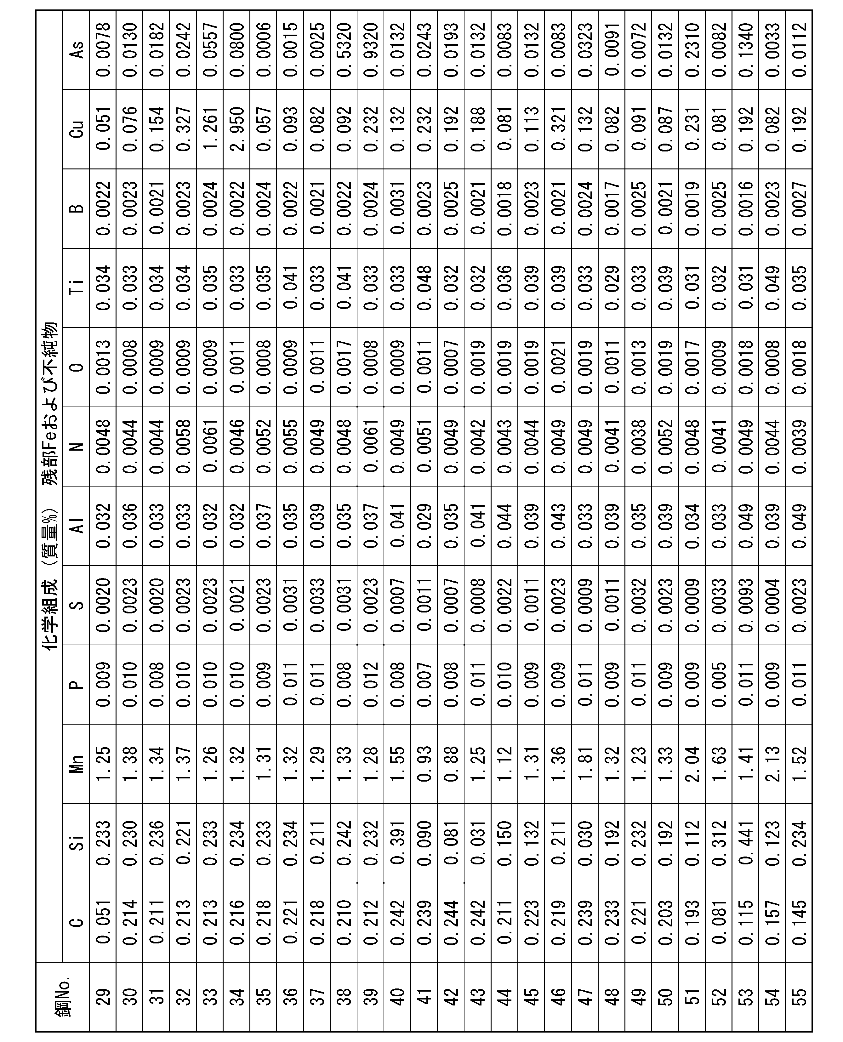
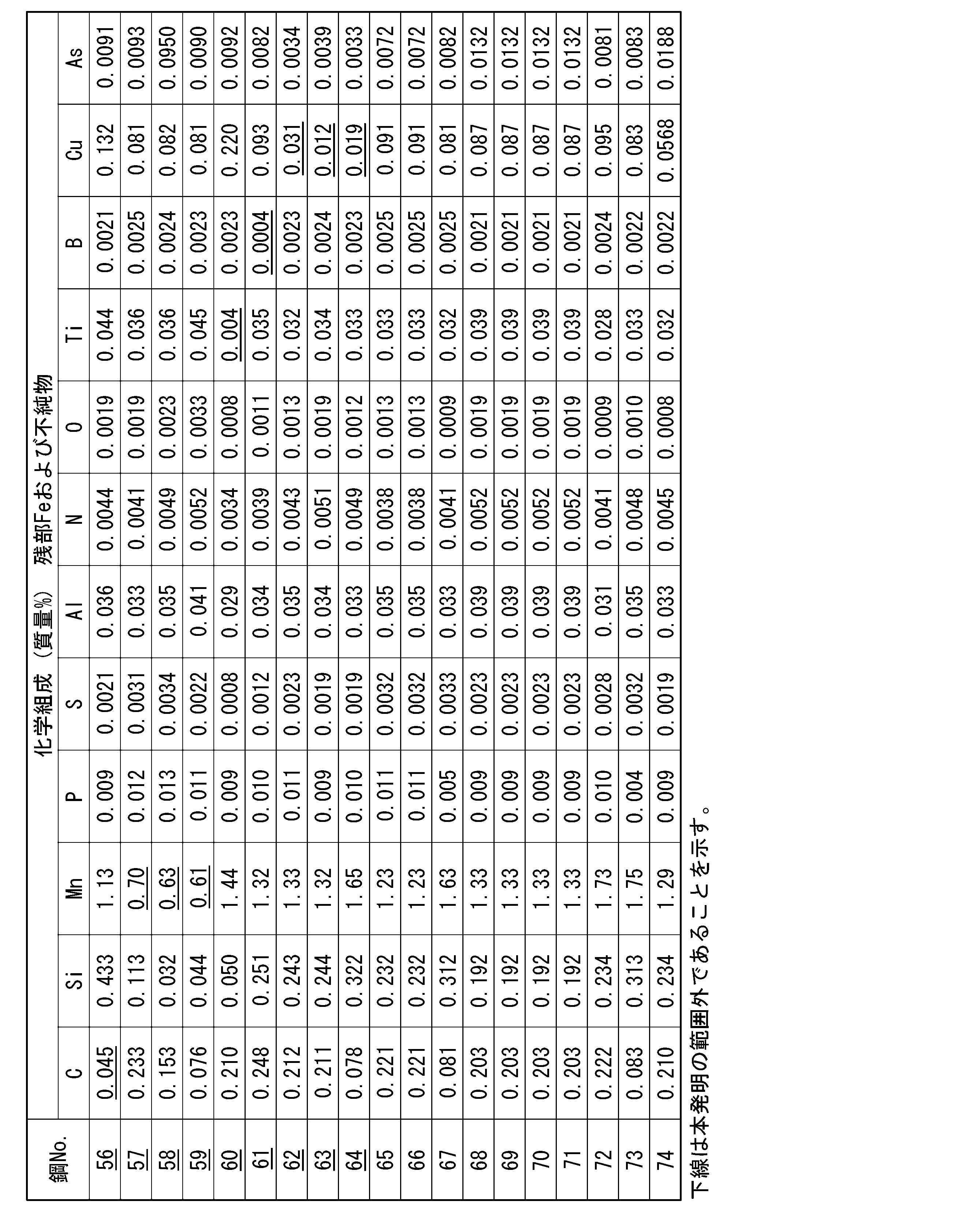
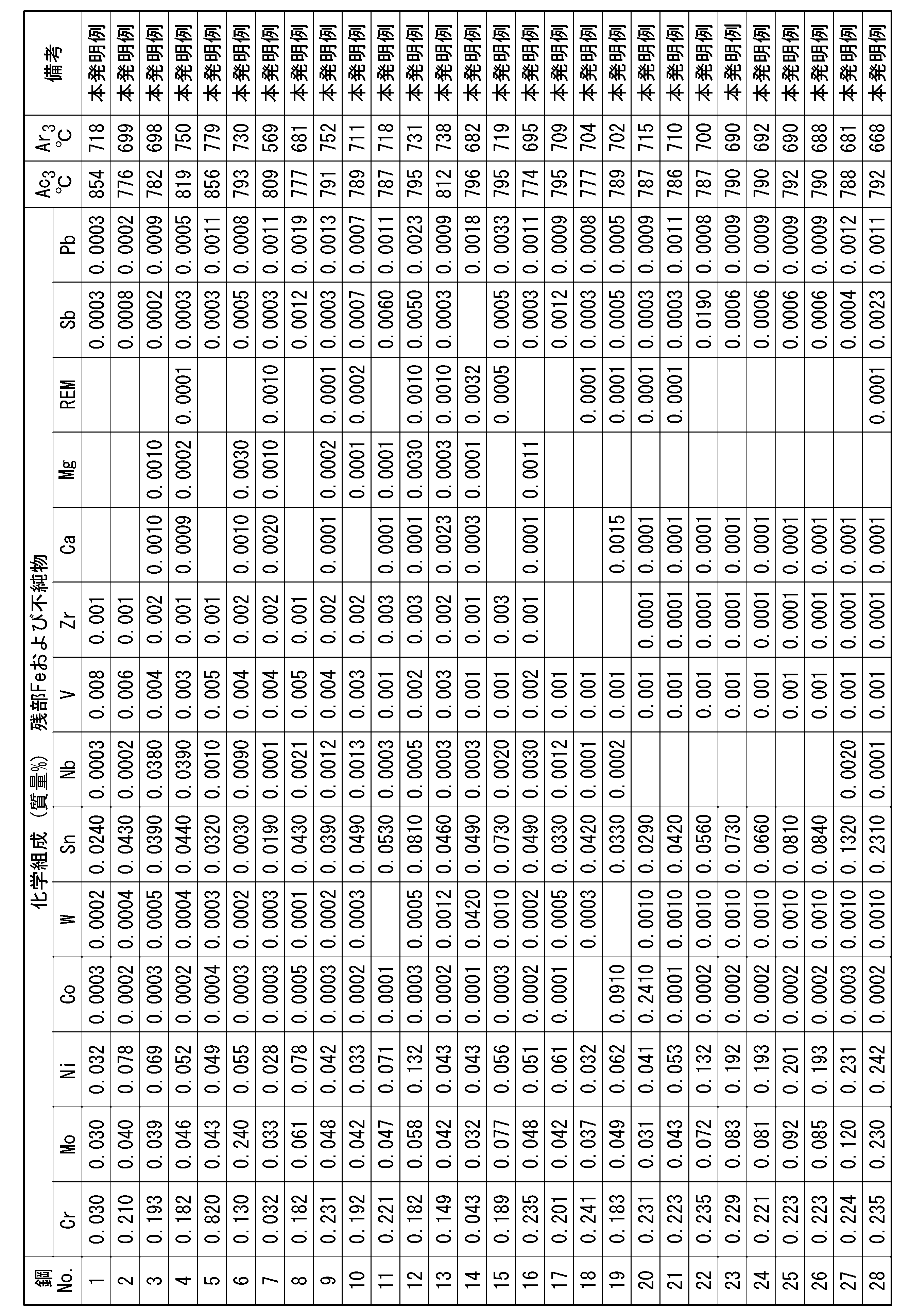
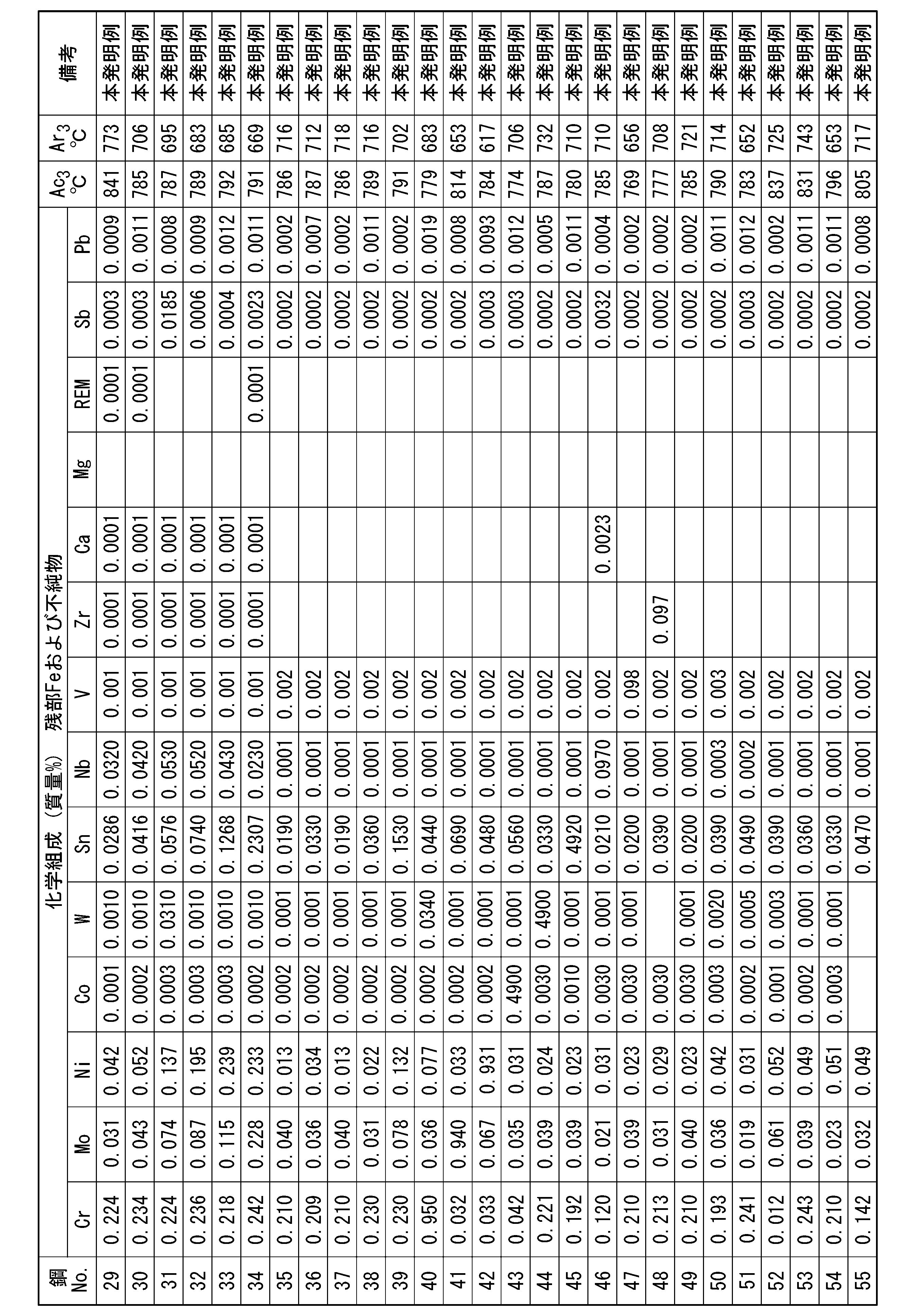

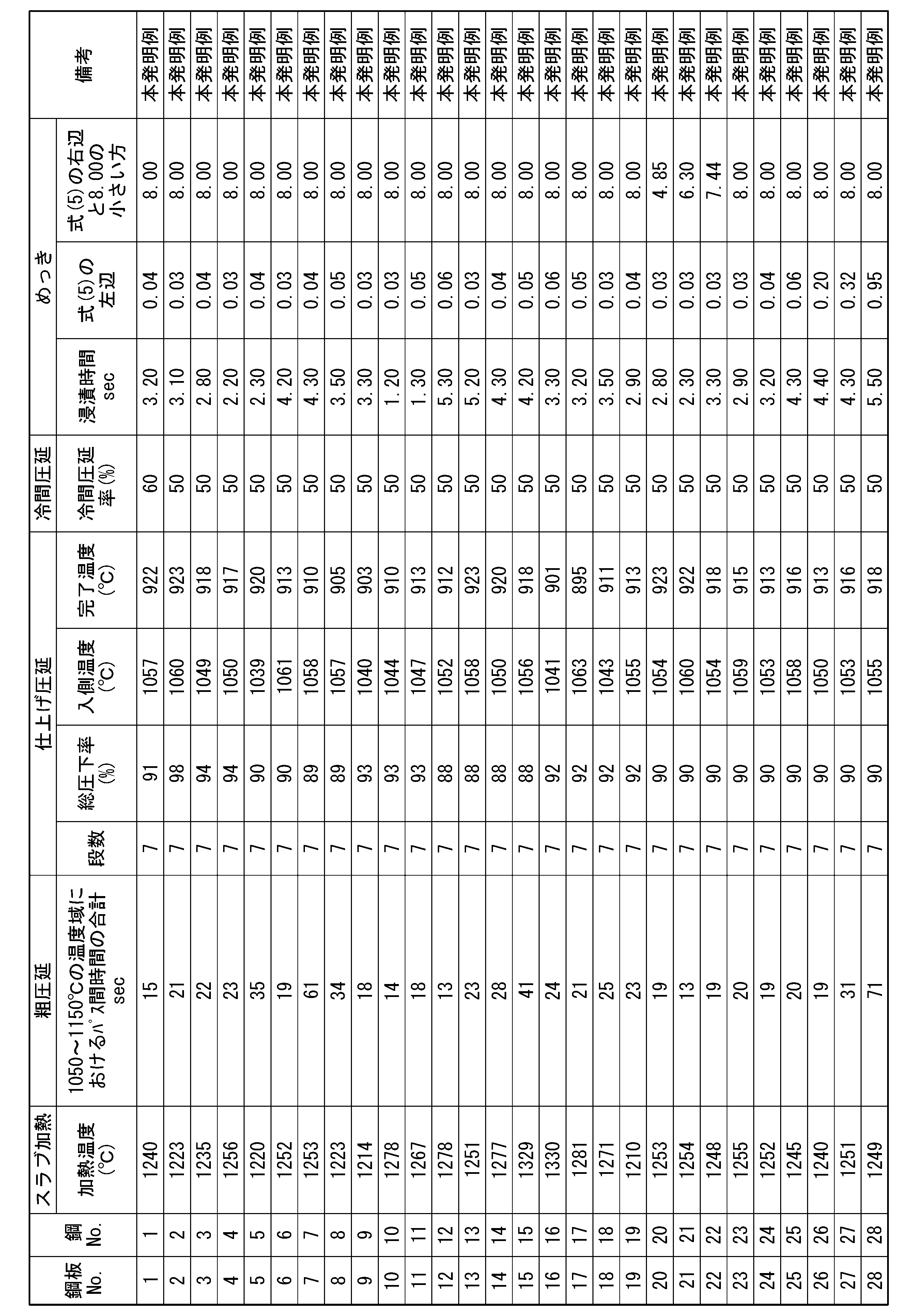
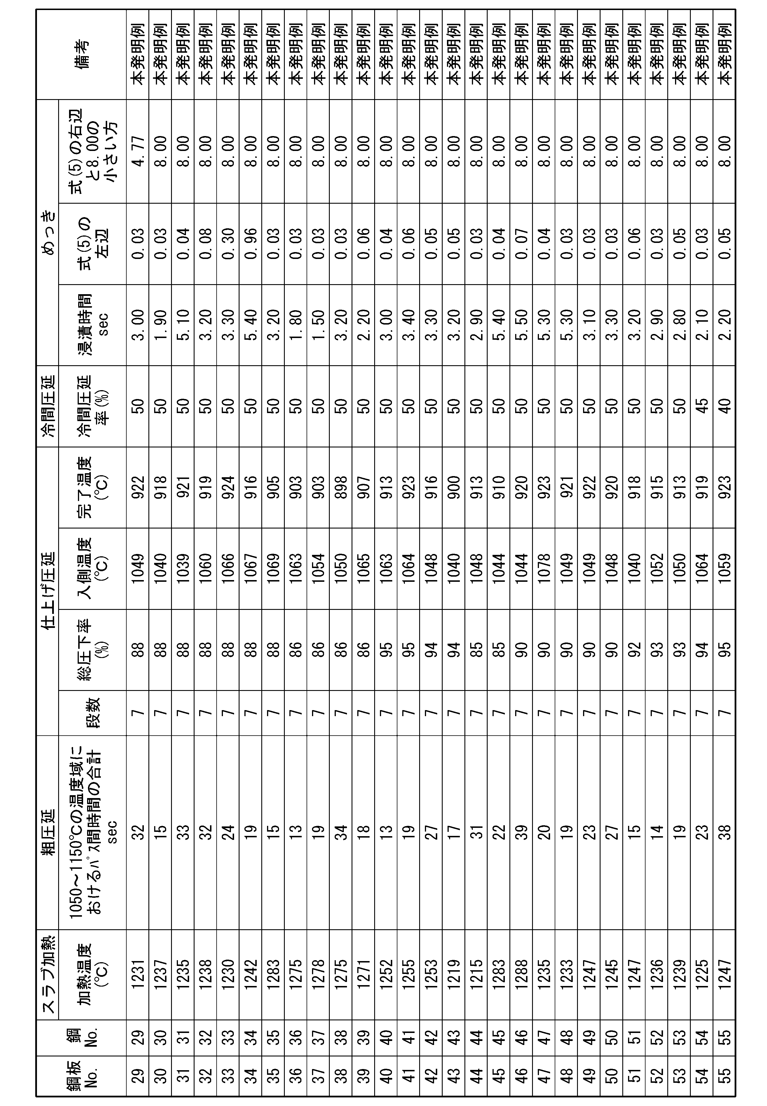

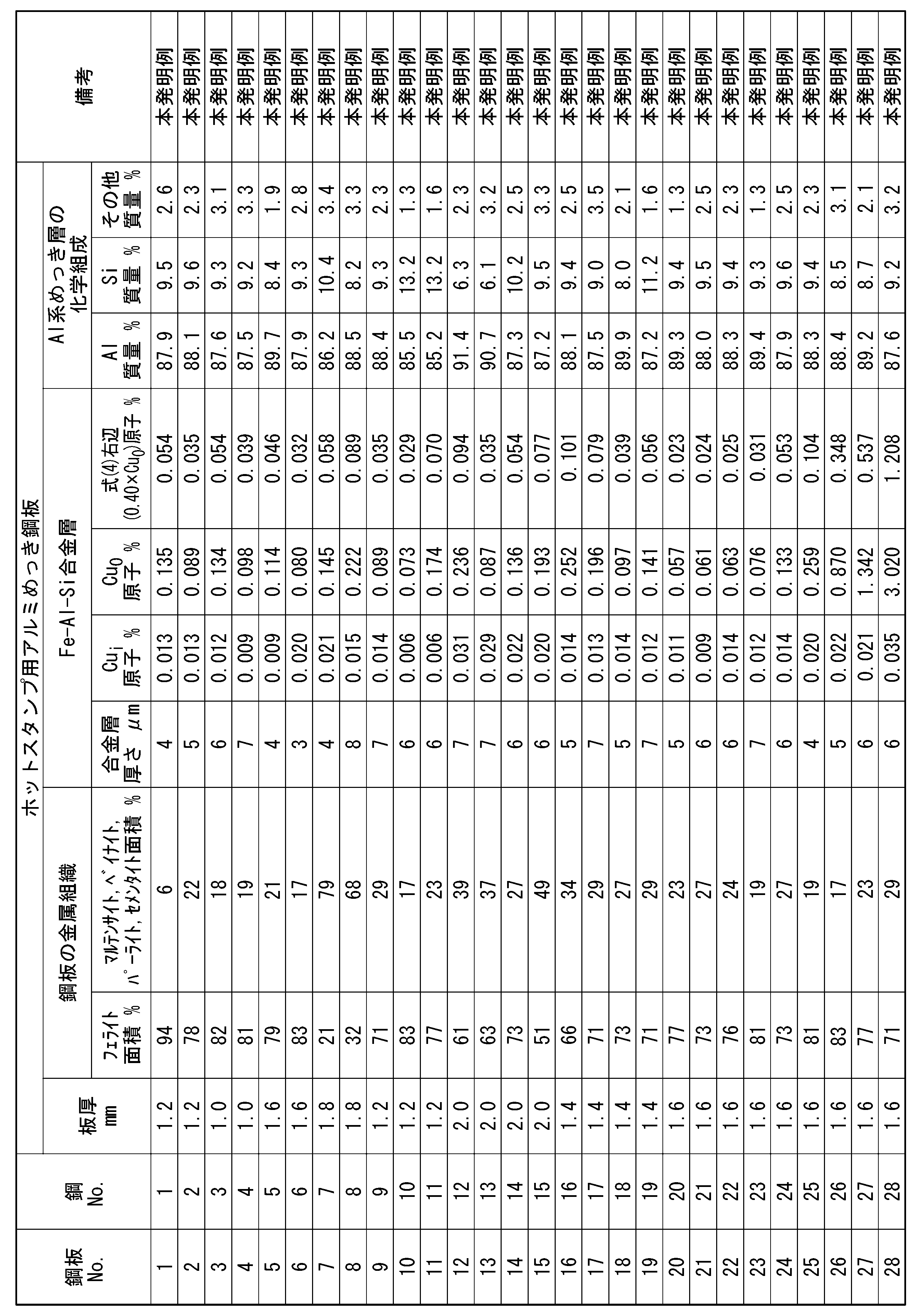
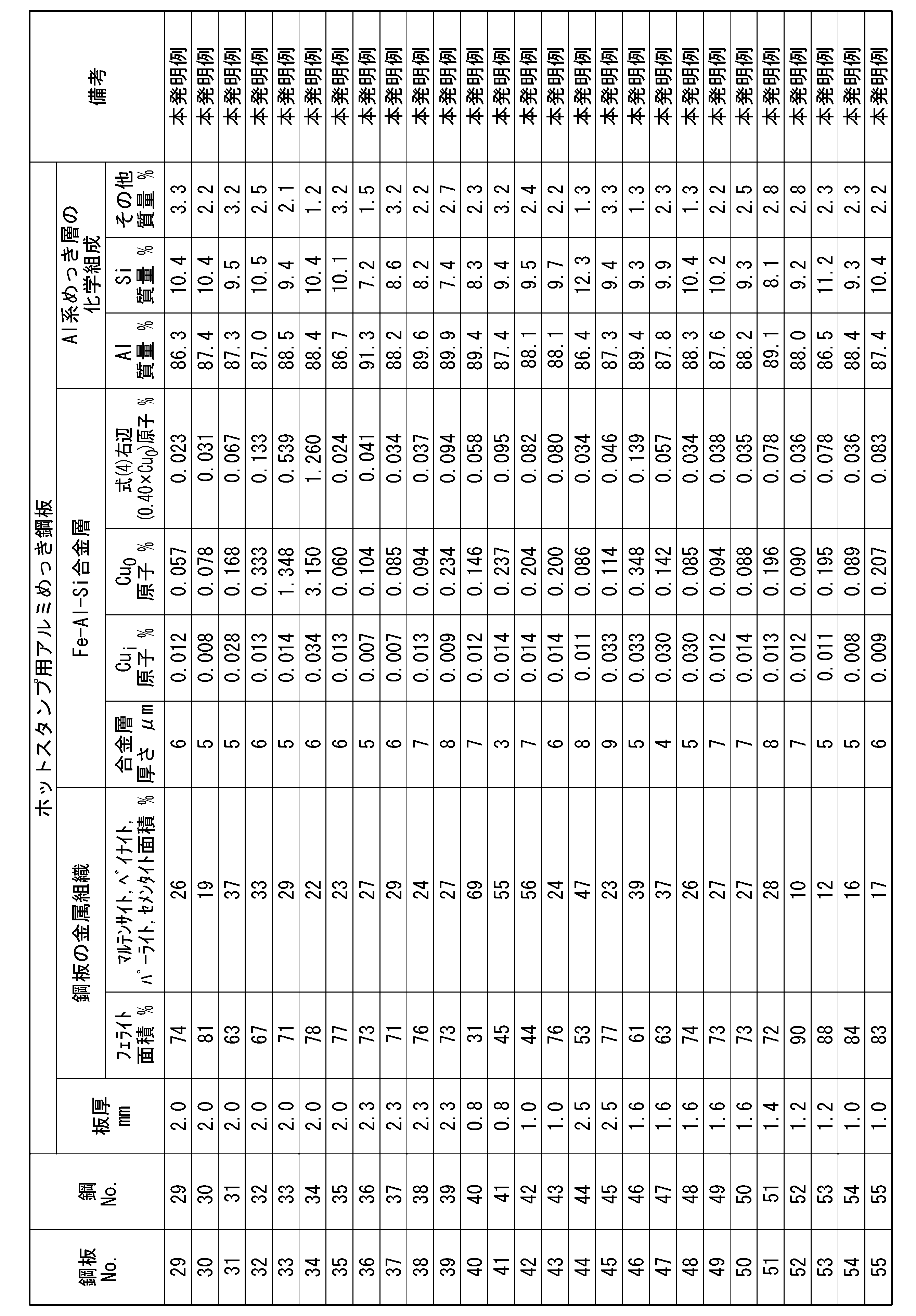
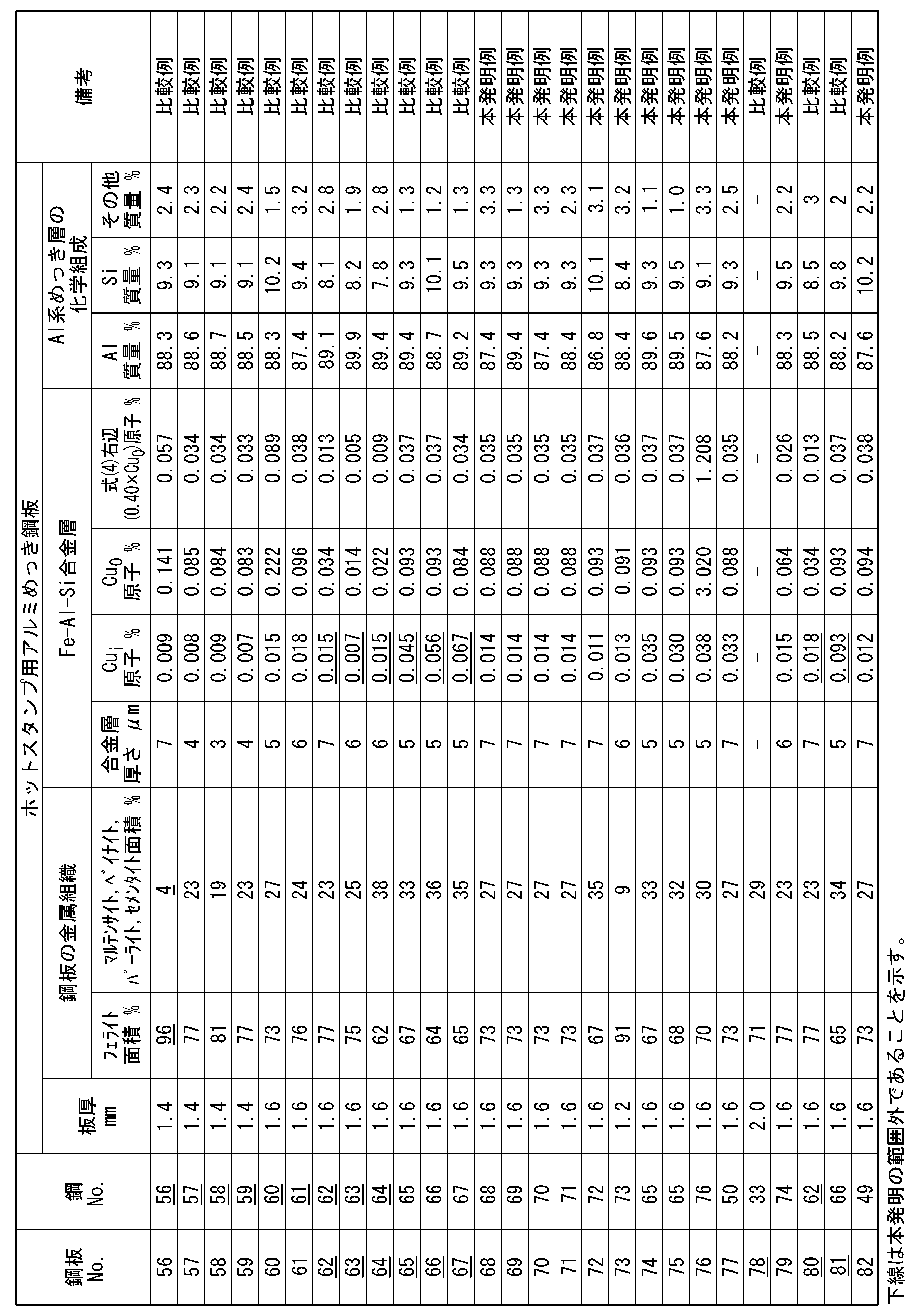
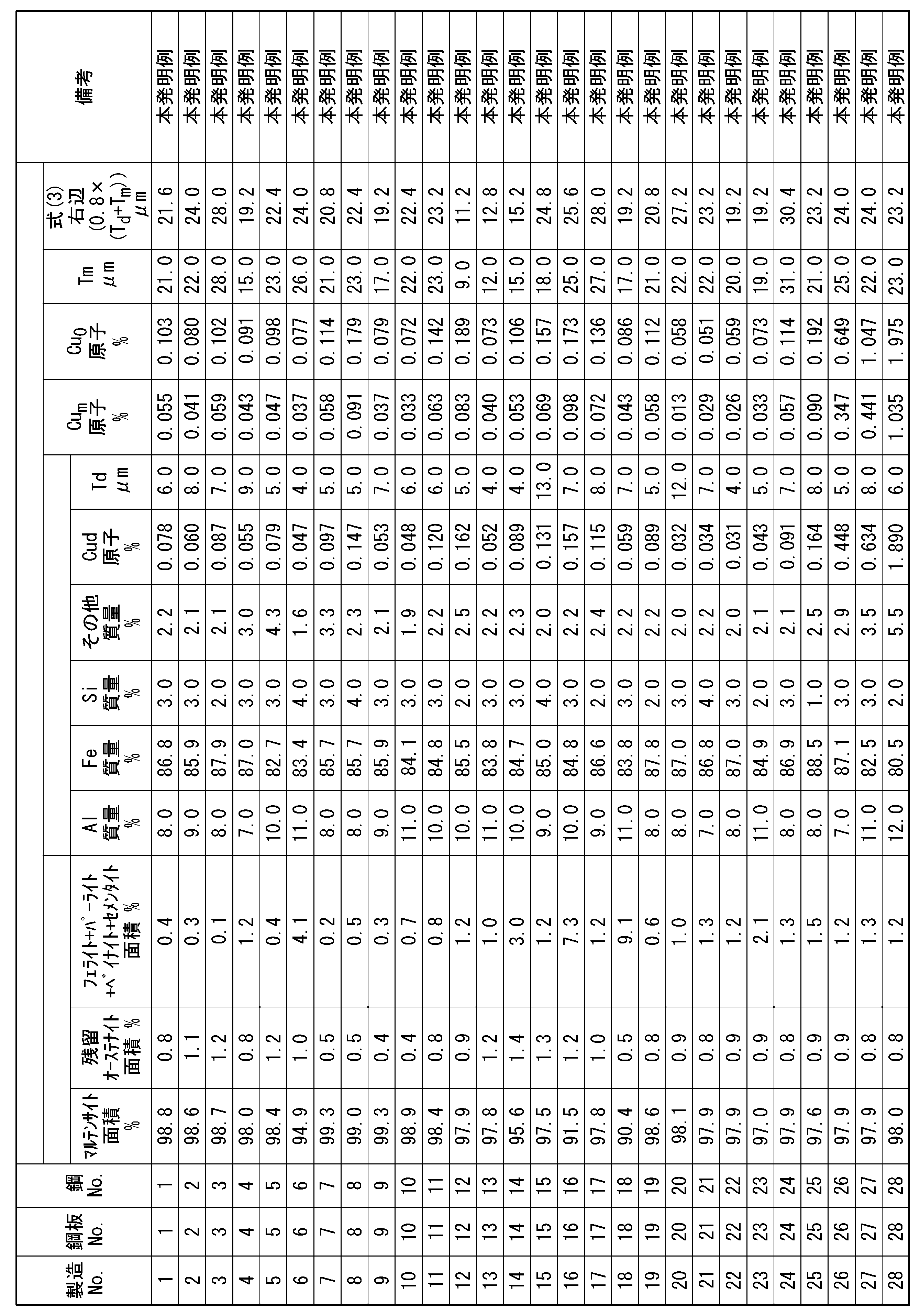

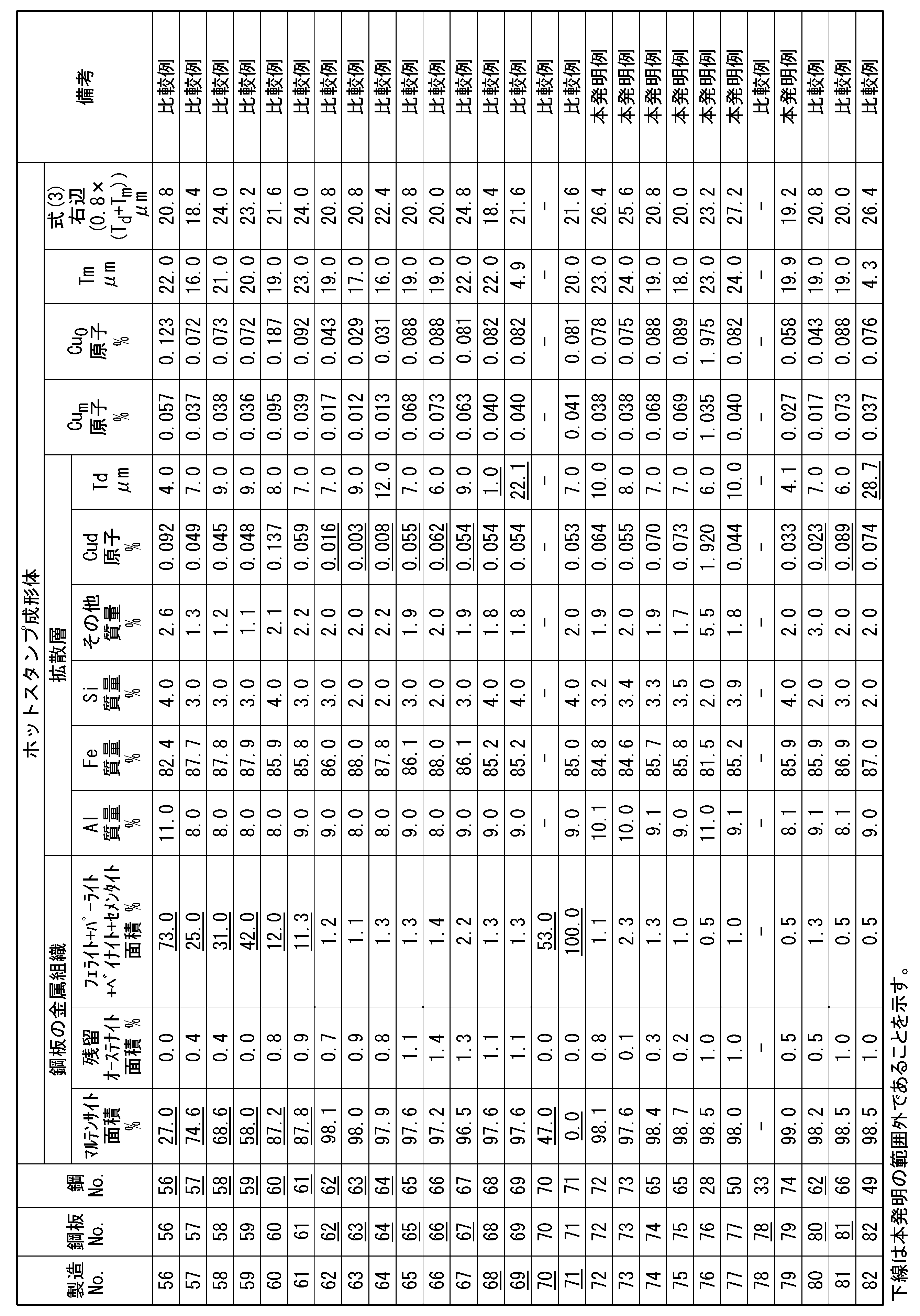

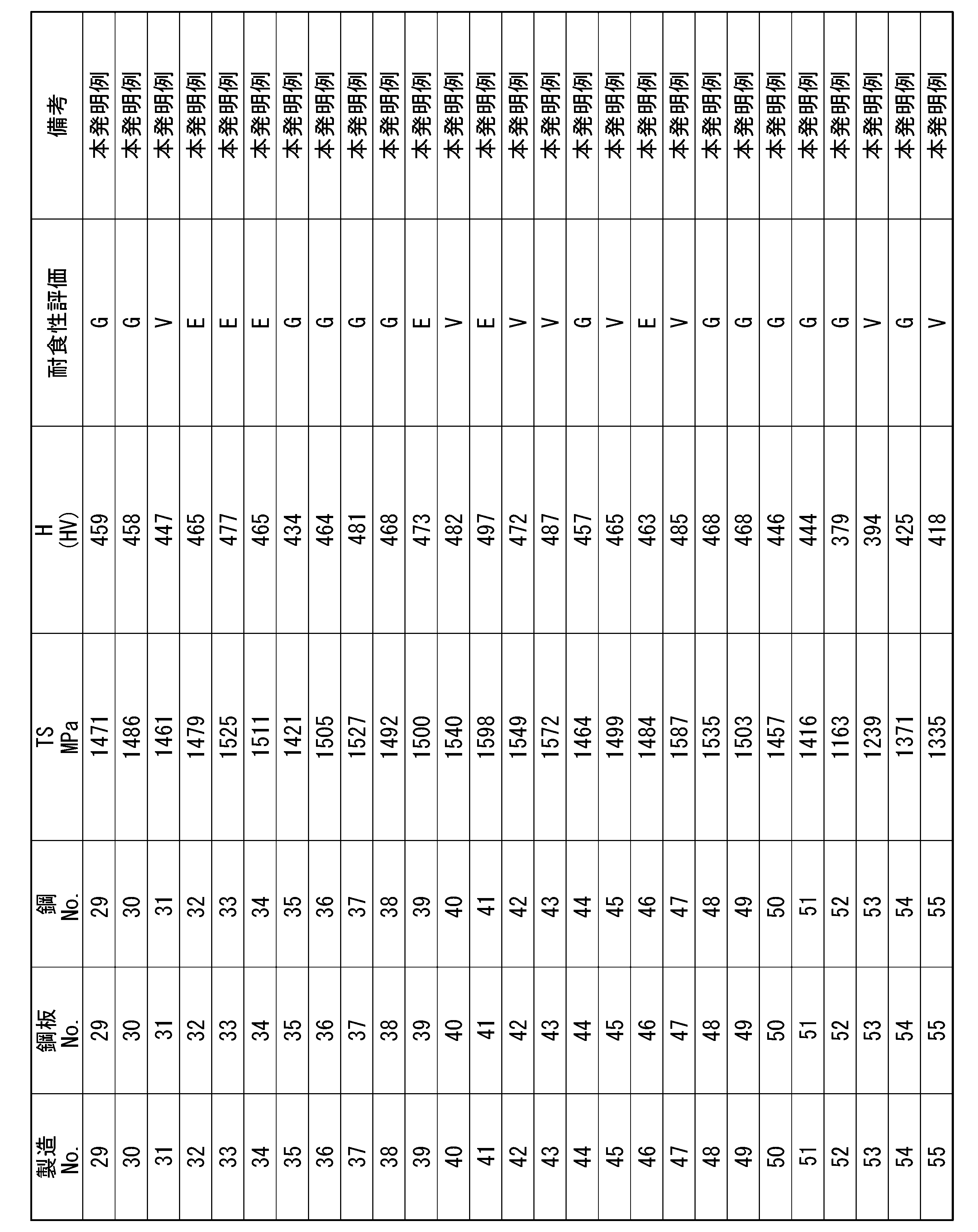
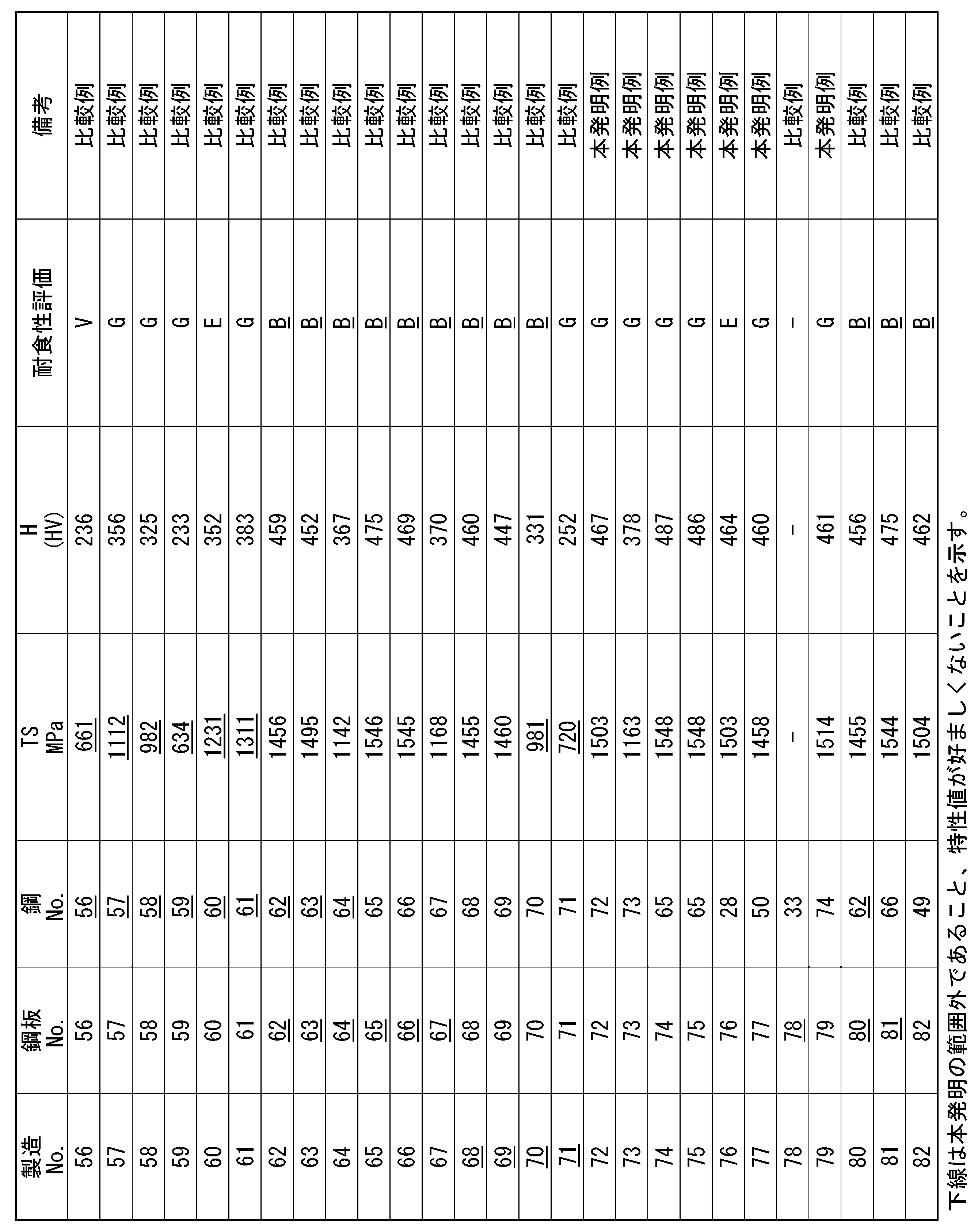
Claims (4)
- 鋼板と、
前記鋼板上に配された拡散層と、
前記拡散層上に配されたFe-Al合金層とからなり、
前記鋼板の化学組成が、質量%で
C :0.050~0.250%、
Si:0.010~2.000%、
Mn:0.80~3.00%、
P :0.100%以下、
S :0.0100%以下、
Al:0.001~0.500%、
N :0.0001~0.0150%、
O :0.1000%以下、
Ti:0.005~0.100%、
B :0.0005~0.0050%、
Cu:0.050~3.000%、
As:0.0005~1.0000%、
Cr:0~1.000%、
Mo:0~1.000%、
Ni:0~3.000%、
Co:0~0.5000%、
W :0~3.0000%、
Sn:0~0.5000%、
Nb:0~0.1000%、
V :0~0.100%、
Zr:0~0.100%、
Ca:0~0.0050%、
Mg:0~0.0050%、
REM:0~0.0050%、
Sb:0~0.0200%、および
Pb:0~0.0100%を含有し、
残部がFeおよび不純物からなり、
前記鋼板の金属組織が、面積%で、
90.0~100.0%のマルテンサイトと、
0.0~3.0%の残留オーステナイトと、
合計で0.0~10.0%のフェライト、パーライト、ベイナイトおよびセメンタイトの1種または2種以上とからなり、
前記拡散層は、化学組成が、質量%で、
Al:0.5%超、20.0%未満、
Fe:80.0%超、99.5%未満、
Si:0.0~15.0%であり、
前記拡散層中のCu濃度が下記式(1)および(2)を満たし、
前記拡散層の平均厚さが下記式(3)を満たし、
前記Fe-Al合金層は、Fe含有量が質量%で40~60質量%であり、Al含有量が質量%で40~60%であるFe-Al相を含むことを特徴とするホットスタンプ成形体。
0.025≦Cud …(1)
Cum<Cud<Cu0 …(2)
2.0≦Td≦0.8×(Td+Tm) …(3)
ただし、前記式(1)および(2)において、Cudは前記拡散層中の原子%でのCu濃度を示し、Cumは前記Fe-Al合金層における前記Fe-Al相の原子%でのCu濃度を示し、Cu0は前記鋼板中の原子%でのCu濃度を示す。
前記式(3)において、Tdは前記拡散層の単位μmでの平均厚さを示し、前記Tmは前記Fe-Al合金層の単位μmでの平均厚さを示す。 - 前記鋼板の化学組成が、質量%で、
Cr:0.020~1.000%、
Mo:0.008~1.000%、
Ni:0.005~3.000%、
Co:0.0005~0.5000%、
W :0.0005~3.0000%、
Sn:0.0005~0.5000%、
Nb:0.0002~0.1000%、
V :0.005~0.100%、
Zr:0.005~0.100%、
Ca:0.0005~0.0050%、
Mg:0.0005~0.0050%、
REM:0.0005~0.0050%、
Sb:0.0005~0.0200%、および
Pb:0.0003~0.0100%
からなる群から選択される1種または2種以上を含有することを特徴とする請求項1に記載のホットスタンプ成形体。 - 鋼板と、
前記鋼板上に配されたFe-Al-Si合金層と、
前記Fe-Al-Si合金層上に配されたAl系めっき層とからなり、
前記鋼板の化学組成が、質量%で
C :0.050~0.250%、
Si:0.010~2.000%、
Mn:0.80~3.00%、
P :0.100%以下、
S :0.0100%以下、
Al:0.001~0.500%、
N :0.0001~0.0150%、
O :0.1000%以下、
Ti:0.005~0.100%、
B :0.0005~0.0050%、
Cu:0.050~3.000%、
As:0.0005~1.0000%、
Cr:0~1.000%、
Mo:0~1.000%、
Ni:0~3.000%、
Co:0~0.5000%、
W :0~3.0000%、
Sn:0~0.5000%、
Nb:0~0.1000%、
V :0~0.100%、
Zr:0~0.100%、
Ca:0~0.0050%、
Mg:0~0.0050%、
REM:0~0.0050%、
Sb:0~0.0200%、および
Pb:0~0.0100%を含有し、
残部がFeおよび不純物からなり、
前記鋼板の金属組織が、面積%で、
20~95%のフェライトと、
合計で5~80%のマルテンサイト、ベイナイト、パーライトおよびセメンタイトの1種または2種以上とからなり、
前記Fe-Al-Si合金層中のCu濃度が下記式(4)を満たし、
前記Al系めっき層は、化学組成が、質量%で、
Al:85.0~95.0%、
Si:5.0~15.0%であることを特徴とするホットスタンプ用アルミめっき鋼板。
Cui≦0.40×Cu0 …(4)
ただし、前記式(4)中のCuiは前記Fe-Al-Si合金層中の原子%でのCu濃度を示し、Cu0は前記鋼板中の原子%でのCu濃度を示す。 - 前記鋼板の化学組成が、質量%で、
Cr:0.020~1.000%、
Mo:0.008~1.000%、
Ni:0.005~3.000%、
Co:0.0005~0.5000%、
W :0.0005~3.0000%、
Sn:0.0005~0.5000%、
Nb:0.0002~0.1000%、
V :0.005~0.100%、
Zr:0.005~0.100%、
Ca:0.0005~0.0050%、
Mg:0.0005~0.0050%、
REM:0.0005~0.0050%、
Sb:0.0005~0.0200%、および
Pb:0.0003~0.0100%
からなる群から選択される1種または2種以上を含有することを特徴とする請求項3に記載のホットスタンプ用アルミめっき鋼板。
Priority Applications (5)
| Application Number | Priority Date | Filing Date | Title |
|---|---|---|---|
| EP24756917.1A EP4667600A4 (en) | 2023-02-16 | 2024-02-14 | HOT-STAMPED BODY AND ALUMINUM-CLAMED STEEL SHEET FOR HOT STAMPING |
| JP2025501182A JPWO2024172076A1 (ja) | 2023-02-16 | 2024-02-14 | |
| CN202480008418.9A CN120569505A (zh) | 2023-02-16 | 2024-02-14 | 热冲压成形体及热冲压用镀铝钢板 |
| KR1020257023832A KR20250126768A (ko) | 2023-02-16 | 2024-02-14 | 핫 스탬프 성형체 및 핫 스탬프용 알루미늄 도금 강판 |
| MX2025009335A MX2025009335A (es) | 2023-02-16 | 2025-08-08 | Cuerpo formado por estampado en caliente y lamina de acero recubierta de aluminio por estampado en caliente |
Applications Claiming Priority (2)
| Application Number | Priority Date | Filing Date | Title |
|---|---|---|---|
| JP2023022724 | 2023-02-16 | ||
| JP2023-022724 | 2023-02-16 |
Publications (1)
| Publication Number | Publication Date |
|---|---|
| WO2024172076A1 true WO2024172076A1 (ja) | 2024-08-22 |
Family
ID=92420026
Family Applications (1)
| Application Number | Title | Priority Date | Filing Date |
|---|---|---|---|
| PCT/JP2024/005045 Ceased WO2024172076A1 (ja) | 2023-02-16 | 2024-02-14 | ホットスタンプ成形体およびホットスタンプ用アルミめっき鋼板 |
Country Status (6)
| Country | Link |
|---|---|
| EP (1) | EP4667600A4 (ja) |
| JP (1) | JPWO2024172076A1 (ja) |
| KR (1) | KR20250126768A (ja) |
| CN (1) | CN120569505A (ja) |
| MX (1) | MX2025009335A (ja) |
| WO (1) | WO2024172076A1 (ja) |
Citations (7)
| Publication number | Priority date | Publication date | Assignee | Title |
|---|---|---|---|---|
| JP2003034845A (ja) | 2001-06-25 | 2003-02-07 | Nippon Steel Corp | 耐食性,耐熱性に優れたホットプレス用アルミ系めっき鋼板およびそれを使用した自動車用部材 |
| JP2013227614A (ja) * | 2012-04-25 | 2013-11-07 | Nippon Steel & Sumitomo Metal Corp | 高い靱性と高い加工性および成型性とを有し水素脆化起因による遅れ破壊特性に優れた高強度鋼板及びその製造方法 |
| WO2021095836A1 (ja) * | 2019-11-13 | 2021-05-20 | 日本製鉄株式会社 | ホットスタンプ用鋼板およびホットスタンプ成形体 |
| WO2021100842A1 (ja) * | 2019-11-22 | 2021-05-27 | 日本製鉄株式会社 | 被覆鋼部材、被覆鋼板およびそれらの製造方法 |
| WO2021230150A1 (ja) * | 2020-05-13 | 2021-11-18 | 日本製鉄株式会社 | ホットスタンプ用鋼板およびホットスタンプ成形体 |
| JP2023022724A (ja) | 2021-08-03 | 2023-02-15 | 日本放送協会 | 撮像素子およびその製造方法 |
| WO2023132289A1 (ja) * | 2022-01-07 | 2023-07-13 | 日本製鉄株式会社 | ホットスタンプ用鋼板およびホットスタンプ成形体 |
Family Cites Families (2)
| Publication number | Priority date | Publication date | Assignee | Title |
|---|---|---|---|---|
| MX2021007154A (es) * | 2019-02-05 | 2021-08-16 | Nippon Steel Corp | Miembro de acero recubierto, lamina de acero recubierta y metodos para fabricar los mismos. |
| KR102330812B1 (ko) * | 2020-06-30 | 2021-11-24 | 현대제철 주식회사 | 열간 프레스용 강판 및 이의 제조 방법 |
-
2024
- 2024-02-14 EP EP24756917.1A patent/EP4667600A4/en active Pending
- 2024-02-14 WO PCT/JP2024/005045 patent/WO2024172076A1/ja not_active Ceased
- 2024-02-14 KR KR1020257023832A patent/KR20250126768A/ko active Pending
- 2024-02-14 CN CN202480008418.9A patent/CN120569505A/zh active Pending
- 2024-02-14 JP JP2025501182A patent/JPWO2024172076A1/ja active Pending
-
2025
- 2025-08-08 MX MX2025009335A patent/MX2025009335A/es unknown
Patent Citations (7)
| Publication number | Priority date | Publication date | Assignee | Title |
|---|---|---|---|---|
| JP2003034845A (ja) | 2001-06-25 | 2003-02-07 | Nippon Steel Corp | 耐食性,耐熱性に優れたホットプレス用アルミ系めっき鋼板およびそれを使用した自動車用部材 |
| JP2013227614A (ja) * | 2012-04-25 | 2013-11-07 | Nippon Steel & Sumitomo Metal Corp | 高い靱性と高い加工性および成型性とを有し水素脆化起因による遅れ破壊特性に優れた高強度鋼板及びその製造方法 |
| WO2021095836A1 (ja) * | 2019-11-13 | 2021-05-20 | 日本製鉄株式会社 | ホットスタンプ用鋼板およびホットスタンプ成形体 |
| WO2021100842A1 (ja) * | 2019-11-22 | 2021-05-27 | 日本製鉄株式会社 | 被覆鋼部材、被覆鋼板およびそれらの製造方法 |
| WO2021230150A1 (ja) * | 2020-05-13 | 2021-11-18 | 日本製鉄株式会社 | ホットスタンプ用鋼板およびホットスタンプ成形体 |
| JP2023022724A (ja) | 2021-08-03 | 2023-02-15 | 日本放送協会 | 撮像素子およびその製造方法 |
| WO2023132289A1 (ja) * | 2022-01-07 | 2023-07-13 | 日本製鉄株式会社 | ホットスタンプ用鋼板およびホットスタンプ成形体 |
Non-Patent Citations (4)
| Title |
|---|
| HAJIME SUTOIMAO TAMURATAIJI NISHIZAWA: "Metallography", 1977, MARUZEN GROUP, pages: 170 |
| See also references of EP4667600A1 |
| TADASHI MAKIIMAO TAMURA, IRON AND STEEL, vol. 67, no. 1, 1987, pages 852 - 866 |
| WILLIAM C.: "Leslie: The Physical Metallurgy of Steels", 1981, HEMISPHERE PUBLISHING CORPORATION, pages: 215 |
Also Published As
| Publication number | Publication date |
|---|---|
| EP4667600A1 (en) | 2025-12-24 |
| CN120569505A (zh) | 2025-08-29 |
| KR20250126768A (ko) | 2025-08-25 |
| MX2025009335A (es) | 2025-09-02 |
| JPWO2024172076A1 (ja) | 2024-08-22 |
| EP4667600A4 (en) | 2026-04-08 |
Similar Documents
| Publication | Publication Date | Title |
|---|---|---|
| RU2599934C2 (ru) | Стальной лист для горячей штамповки, способ его изготовления и изделие из горячештампованного стального листа | |
| JP6540245B2 (ja) | 形状凍結性に優れた高強度鋼板およびその製造方法 | |
| JP7541653B1 (ja) | 鋼板および部材、ならびに、それらの製造方法 | |
| JP7684586B2 (ja) | ホットスタンプ成形体 | |
| WO2023190867A1 (ja) | 鋼部材及び鋼板 | |
| JP7239060B2 (ja) | ホットスタンプ成形体 | |
| JP7549277B2 (ja) | ホットスタンプ用鋼板およびホットスタンプ成形体 | |
| KR20250028466A (ko) | 강판 | |
| KR20240095275A (ko) | 강 부재 및 강판 | |
| CN115135798B (zh) | 热冲压构件及其制造方法 | |
| CN116568828A (zh) | 经涂覆的钢板和高强度压制硬化钢部件及其制造方法 | |
| JP7239059B2 (ja) | ホットスタンプ成形体 | |
| JP7817597B2 (ja) | ホットスタンプ用鋼板およびホットスタンプ成形体 | |
| JP7617452B2 (ja) | 鋼材 | |
| JP7705065B2 (ja) | 熱延鋼板 | |
| JP2025528034A (ja) | プレス硬化後のパウダリング性に優れた鋼板及びその製造方法 | |
| KR20250126768A (ko) | 핫 스탬프 성형체 및 핫 스탬프용 알루미늄 도금 강판 | |
| JP7708344B1 (ja) | 亜鉛めっき鋼板および部材、ならびに、それらの製造方法 | |
| JP7619534B1 (ja) | 鋼板、部材およびそれらの製造方法 | |
| JP7780113B2 (ja) | ホットスタンプ成形体 | |
| JP7737059B2 (ja) | ホットスタンプ成形体 | |
| JP7748014B2 (ja) | 鋼板 | |
| JP7704308B2 (ja) | 鋼板、部材およびそれらの製造方法 | |
| JP7740597B2 (ja) | 鋼板、部材およびそれらの製造方法 | |
| CA3281272A1 (en) | Hot-stamp formed body and aluminum-coated steel sheet for hot stamping |
Legal Events
| Date | Code | Title | Description |
|---|---|---|---|
| 121 | Ep: the epo has been informed by wipo that ep was designated in this application |
Ref document number: 24756917 Country of ref document: EP Kind code of ref document: A1 |
|
| WWE | Wipo information: entry into national phase |
Ref document number: 2025501182 Country of ref document: JP |
|
| ENP | Entry into the national phase |
Ref document number: 1020257023832 Country of ref document: KR Free format text: ST27 STATUS EVENT CODE: A-0-1-A10-A15-NAP-PA0105 (AS PROVIDED BY THE NATIONAL OFFICE) |
|
| WWE | Wipo information: entry into national phase |
Ref document number: 1020257023832 Country of ref document: KR |
|
| WWE | Wipo information: entry into national phase |
Ref document number: 202480008418.9 Country of ref document: CN |
|
| WWE | Wipo information: entry into national phase |
Ref document number: 202517075214 Country of ref document: IN |
|
| WWE | Wipo information: entry into national phase |
Ref document number: MX/A/2025/009335 Country of ref document: MX |
|
| WWE | Wipo information: entry into national phase |
Ref document number: 2501005407 Country of ref document: TH |
|
| WWP | Wipo information: published in national office |
Ref document number: 1020257023832 Country of ref document: KR |
|
| WWP | Wipo information: published in national office |
Ref document number: 202517075214 Country of ref document: IN Ref document number: 202480008418.9 Country of ref document: CN |
|
| WWP | Wipo information: published in national office |
Ref document number: MX/A/2025/009335 Country of ref document: MX |
|
| WWE | Wipo information: entry into national phase |
Ref document number: 2024756917 Country of ref document: EP |
|
| NENP | Non-entry into the national phase |
Ref country code: DE |
|
| ENP | Entry into the national phase |
Ref document number: 2024756917 Country of ref document: EP Effective date: 20250916 |
|
| WWP | Wipo information: published in national office |
Ref document number: 2024756917 Country of ref document: EP |