WO2024177008A1 - 原子層堆積法による成膜方法 - Google Patents
原子層堆積法による成膜方法 Download PDFInfo
- Publication number
- WO2024177008A1 WO2024177008A1 PCT/JP2024/005773 JP2024005773W WO2024177008A1 WO 2024177008 A1 WO2024177008 A1 WO 2024177008A1 JP 2024005773 W JP2024005773 W JP 2024005773W WO 2024177008 A1 WO2024177008 A1 WO 2024177008A1
- Authority
- WO
- WIPO (PCT)
- Prior art keywords
- raw material
- evaporator
- thin film
- material compound
- producing
- Prior art date
- Legal status (The legal status is an assumption and is not a legal conclusion. Google has not performed a legal analysis and makes no representation as to the accuracy of the status listed.)
- Ceased
Links
Images


Classifications
-
- C—CHEMISTRY; METALLURGY
- C23—COATING METALLIC MATERIAL; COATING MATERIAL WITH METALLIC MATERIAL; CHEMICAL SURFACE TREATMENT; DIFFUSION TREATMENT OF METALLIC MATERIAL; COATING BY VACUUM EVAPORATION, BY SPUTTERING, BY ION IMPLANTATION OR BY CHEMICAL VAPOUR DEPOSITION, IN GENERAL; INHIBITING CORROSION OF METALLIC MATERIAL OR INCRUSTATION IN GENERAL
- C23C—COATING METALLIC MATERIAL; COATING MATERIAL WITH METALLIC MATERIAL; SURFACE TREATMENT OF METALLIC MATERIAL BY DIFFUSION INTO THE SURFACE, BY CHEMICAL CONVERSION OR SUBSTITUTION; COATING BY VACUUM EVAPORATION, BY SPUTTERING, BY ION IMPLANTATION OR BY CHEMICAL VAPOUR DEPOSITION, IN GENERAL
- C23C16/00—Chemical coating by decomposition of gaseous compounds, without leaving reaction products of surface material in the coating, i.e. chemical vapour deposition [CVD] processes
- C23C16/44—Chemical coating by decomposition of gaseous compounds, without leaving reaction products of surface material in the coating, i.e. chemical vapour deposition [CVD] processes characterised by the method of coating
- C23C16/455—Chemical coating by decomposition of gaseous compounds, without leaving reaction products of surface material in the coating, i.e. chemical vapour deposition [CVD] processes characterised by the method of coating characterised by the method used for introducing gases into reaction chamber or for modifying gas flows in reaction chamber
- C23C16/45523—Pulsed gas flow or change of composition over time
- C23C16/45525—Atomic layer deposition [ALD]
- C23C16/45527—Atomic layer deposition [ALD] characterized by the ALD cycle, e.g. different flows or temperatures during half-reactions, unusual pulsing sequence, use of precursor mixtures or auxiliary reactants or activations
-
- C—CHEMISTRY; METALLURGY
- C23—COATING METALLIC MATERIAL; COATING MATERIAL WITH METALLIC MATERIAL; CHEMICAL SURFACE TREATMENT; DIFFUSION TREATMENT OF METALLIC MATERIAL; COATING BY VACUUM EVAPORATION, BY SPUTTERING, BY ION IMPLANTATION OR BY CHEMICAL VAPOUR DEPOSITION, IN GENERAL; INHIBITING CORROSION OF METALLIC MATERIAL OR INCRUSTATION IN GENERAL
- C23C—COATING METALLIC MATERIAL; COATING MATERIAL WITH METALLIC MATERIAL; SURFACE TREATMENT OF METALLIC MATERIAL BY DIFFUSION INTO THE SURFACE, BY CHEMICAL CONVERSION OR SUBSTITUTION; COATING BY VACUUM EVAPORATION, BY SPUTTERING, BY ION IMPLANTATION OR BY CHEMICAL VAPOUR DEPOSITION, IN GENERAL
- C23C16/00—Chemical coating by decomposition of gaseous compounds, without leaving reaction products of surface material in the coating, i.e. chemical vapour deposition [CVD] processes
- C23C16/44—Chemical coating by decomposition of gaseous compounds, without leaving reaction products of surface material in the coating, i.e. chemical vapour deposition [CVD] processes characterised by the method of coating
- C23C16/455—Chemical coating by decomposition of gaseous compounds, without leaving reaction products of surface material in the coating, i.e. chemical vapour deposition [CVD] processes characterised by the method of coating characterised by the method used for introducing gases into reaction chamber or for modifying gas flows in reaction chamber
- C23C16/45523—Pulsed gas flow or change of composition over time
- C23C16/45525—Atomic layer deposition [ALD]
- C23C16/45553—Atomic layer deposition [ALD] characterized by the use of precursors specially adapted for ALD
-
- C—CHEMISTRY; METALLURGY
- C23—COATING METALLIC MATERIAL; COATING MATERIAL WITH METALLIC MATERIAL; CHEMICAL SURFACE TREATMENT; DIFFUSION TREATMENT OF METALLIC MATERIAL; COATING BY VACUUM EVAPORATION, BY SPUTTERING, BY ION IMPLANTATION OR BY CHEMICAL VAPOUR DEPOSITION, IN GENERAL; INHIBITING CORROSION OF METALLIC MATERIAL OR INCRUSTATION IN GENERAL
- C23C—COATING METALLIC MATERIAL; COATING MATERIAL WITH METALLIC MATERIAL; SURFACE TREATMENT OF METALLIC MATERIAL BY DIFFUSION INTO THE SURFACE, BY CHEMICAL CONVERSION OR SUBSTITUTION; COATING BY VACUUM EVAPORATION, BY SPUTTERING, BY ION IMPLANTATION OR BY CHEMICAL VAPOUR DEPOSITION, IN GENERAL
- C23C16/00—Chemical coating by decomposition of gaseous compounds, without leaving reaction products of surface material in the coating, i.e. chemical vapour deposition [CVD] processes
- C23C16/06—Chemical coating by decomposition of gaseous compounds, without leaving reaction products of surface material in the coating, i.e. chemical vapour deposition [CVD] processes characterised by the deposition of metallic material
- C23C16/18—Chemical coating by decomposition of gaseous compounds, without leaving reaction products of surface material in the coating, i.e. chemical vapour deposition [CVD] processes characterised by the deposition of metallic material from metallo-organic compounds
-
- C—CHEMISTRY; METALLURGY
- C23—COATING METALLIC MATERIAL; COATING MATERIAL WITH METALLIC MATERIAL; CHEMICAL SURFACE TREATMENT; DIFFUSION TREATMENT OF METALLIC MATERIAL; COATING BY VACUUM EVAPORATION, BY SPUTTERING, BY ION IMPLANTATION OR BY CHEMICAL VAPOUR DEPOSITION, IN GENERAL; INHIBITING CORROSION OF METALLIC MATERIAL OR INCRUSTATION IN GENERAL
- C23C—COATING METALLIC MATERIAL; COATING MATERIAL WITH METALLIC MATERIAL; SURFACE TREATMENT OF METALLIC MATERIAL BY DIFFUSION INTO THE SURFACE, BY CHEMICAL CONVERSION OR SUBSTITUTION; COATING BY VACUUM EVAPORATION, BY SPUTTERING, BY ION IMPLANTATION OR BY CHEMICAL VAPOUR DEPOSITION, IN GENERAL
- C23C16/00—Chemical coating by decomposition of gaseous compounds, without leaving reaction products of surface material in the coating, i.e. chemical vapour deposition [CVD] processes
- C23C16/44—Chemical coating by decomposition of gaseous compounds, without leaving reaction products of surface material in the coating, i.e. chemical vapour deposition [CVD] processes characterised by the method of coating
- C23C16/4401—Means for minimising impurities, e.g. dust, moisture or residual gas, in the reaction chamber
- C23C16/4402—Reduction of impurities in the source gas
-
- C—CHEMISTRY; METALLURGY
- C23—COATING METALLIC MATERIAL; COATING MATERIAL WITH METALLIC MATERIAL; CHEMICAL SURFACE TREATMENT; DIFFUSION TREATMENT OF METALLIC MATERIAL; COATING BY VACUUM EVAPORATION, BY SPUTTERING, BY ION IMPLANTATION OR BY CHEMICAL VAPOUR DEPOSITION, IN GENERAL; INHIBITING CORROSION OF METALLIC MATERIAL OR INCRUSTATION IN GENERAL
- C23C—COATING METALLIC MATERIAL; COATING MATERIAL WITH METALLIC MATERIAL; SURFACE TREATMENT OF METALLIC MATERIAL BY DIFFUSION INTO THE SURFACE, BY CHEMICAL CONVERSION OR SUBSTITUTION; COATING BY VACUUM EVAPORATION, BY SPUTTERING, BY ION IMPLANTATION OR BY CHEMICAL VAPOUR DEPOSITION, IN GENERAL
- C23C16/00—Chemical coating by decomposition of gaseous compounds, without leaving reaction products of surface material in the coating, i.e. chemical vapour deposition [CVD] processes
- C23C16/44—Chemical coating by decomposition of gaseous compounds, without leaving reaction products of surface material in the coating, i.e. chemical vapour deposition [CVD] processes characterised by the method of coating
- C23C16/4401—Means for minimising impurities, e.g. dust, moisture or residual gas, in the reaction chamber
- C23C16/4408—Means for minimising impurities, e.g. dust, moisture or residual gas, in the reaction chamber by purging residual gases from the reaction chamber or gas lines
-
- C—CHEMISTRY; METALLURGY
- C23—COATING METALLIC MATERIAL; COATING MATERIAL WITH METALLIC MATERIAL; CHEMICAL SURFACE TREATMENT; DIFFUSION TREATMENT OF METALLIC MATERIAL; COATING BY VACUUM EVAPORATION, BY SPUTTERING, BY ION IMPLANTATION OR BY CHEMICAL VAPOUR DEPOSITION, IN GENERAL; INHIBITING CORROSION OF METALLIC MATERIAL OR INCRUSTATION IN GENERAL
- C23C—COATING METALLIC MATERIAL; COATING MATERIAL WITH METALLIC MATERIAL; SURFACE TREATMENT OF METALLIC MATERIAL BY DIFFUSION INTO THE SURFACE, BY CHEMICAL CONVERSION OR SUBSTITUTION; COATING BY VACUUM EVAPORATION, BY SPUTTERING, BY ION IMPLANTATION OR BY CHEMICAL VAPOUR DEPOSITION, IN GENERAL
- C23C16/00—Chemical coating by decomposition of gaseous compounds, without leaving reaction products of surface material in the coating, i.e. chemical vapour deposition [CVD] processes
- C23C16/44—Chemical coating by decomposition of gaseous compounds, without leaving reaction products of surface material in the coating, i.e. chemical vapour deposition [CVD] processes characterised by the method of coating
- C23C16/4412—Details relating to the exhausts, e.g. pumps, filters, scrubbers, particle traps
-
- C—CHEMISTRY; METALLURGY
- C23—COATING METALLIC MATERIAL; COATING MATERIAL WITH METALLIC MATERIAL; CHEMICAL SURFACE TREATMENT; DIFFUSION TREATMENT OF METALLIC MATERIAL; COATING BY VACUUM EVAPORATION, BY SPUTTERING, BY ION IMPLANTATION OR BY CHEMICAL VAPOUR DEPOSITION, IN GENERAL; INHIBITING CORROSION OF METALLIC MATERIAL OR INCRUSTATION IN GENERAL
- C23C—COATING METALLIC MATERIAL; COATING MATERIAL WITH METALLIC MATERIAL; SURFACE TREATMENT OF METALLIC MATERIAL BY DIFFUSION INTO THE SURFACE, BY CHEMICAL CONVERSION OR SUBSTITUTION; COATING BY VACUUM EVAPORATION, BY SPUTTERING, BY ION IMPLANTATION OR BY CHEMICAL VAPOUR DEPOSITION, IN GENERAL
- C23C16/00—Chemical coating by decomposition of gaseous compounds, without leaving reaction products of surface material in the coating, i.e. chemical vapour deposition [CVD] processes
- C23C16/44—Chemical coating by decomposition of gaseous compounds, without leaving reaction products of surface material in the coating, i.e. chemical vapour deposition [CVD] processes characterised by the method of coating
- C23C16/448—Chemical coating by decomposition of gaseous compounds, without leaving reaction products of surface material in the coating, i.e. chemical vapour deposition [CVD] processes characterised by the method of coating characterised by the method used for generating reactive gas streams, e.g. by evaporation or sublimation of precursor materials
-
- C—CHEMISTRY; METALLURGY
- C23—COATING METALLIC MATERIAL; COATING MATERIAL WITH METALLIC MATERIAL; CHEMICAL SURFACE TREATMENT; DIFFUSION TREATMENT OF METALLIC MATERIAL; COATING BY VACUUM EVAPORATION, BY SPUTTERING, BY ION IMPLANTATION OR BY CHEMICAL VAPOUR DEPOSITION, IN GENERAL; INHIBITING CORROSION OF METALLIC MATERIAL OR INCRUSTATION IN GENERAL
- C23C—COATING METALLIC MATERIAL; COATING MATERIAL WITH METALLIC MATERIAL; SURFACE TREATMENT OF METALLIC MATERIAL BY DIFFUSION INTO THE SURFACE, BY CHEMICAL CONVERSION OR SUBSTITUTION; COATING BY VACUUM EVAPORATION, BY SPUTTERING, BY ION IMPLANTATION OR BY CHEMICAL VAPOUR DEPOSITION, IN GENERAL
- C23C16/00—Chemical coating by decomposition of gaseous compounds, without leaving reaction products of surface material in the coating, i.e. chemical vapour deposition [CVD] processes
- C23C16/44—Chemical coating by decomposition of gaseous compounds, without leaving reaction products of surface material in the coating, i.e. chemical vapour deposition [CVD] processes characterised by the method of coating
- C23C16/448—Chemical coating by decomposition of gaseous compounds, without leaving reaction products of surface material in the coating, i.e. chemical vapour deposition [CVD] processes characterised by the method of coating characterised by the method used for generating reactive gas streams, e.g. by evaporation or sublimation of precursor materials
- C23C16/4481—Chemical coating by decomposition of gaseous compounds, without leaving reaction products of surface material in the coating, i.e. chemical vapour deposition [CVD] processes characterised by the method of coating characterised by the method used for generating reactive gas streams, e.g. by evaporation or sublimation of precursor materials by evaporation using carrier gas in contact with the source material
-
- C—CHEMISTRY; METALLURGY
- C23—COATING METALLIC MATERIAL; COATING MATERIAL WITH METALLIC MATERIAL; CHEMICAL SURFACE TREATMENT; DIFFUSION TREATMENT OF METALLIC MATERIAL; COATING BY VACUUM EVAPORATION, BY SPUTTERING, BY ION IMPLANTATION OR BY CHEMICAL VAPOUR DEPOSITION, IN GENERAL; INHIBITING CORROSION OF METALLIC MATERIAL OR INCRUSTATION IN GENERAL
- C23C—COATING METALLIC MATERIAL; COATING MATERIAL WITH METALLIC MATERIAL; SURFACE TREATMENT OF METALLIC MATERIAL BY DIFFUSION INTO THE SURFACE, BY CHEMICAL CONVERSION OR SUBSTITUTION; COATING BY VACUUM EVAPORATION, BY SPUTTERING, BY ION IMPLANTATION OR BY CHEMICAL VAPOUR DEPOSITION, IN GENERAL
- C23C16/00—Chemical coating by decomposition of gaseous compounds, without leaving reaction products of surface material in the coating, i.e. chemical vapour deposition [CVD] processes
- C23C16/44—Chemical coating by decomposition of gaseous compounds, without leaving reaction products of surface material in the coating, i.e. chemical vapour deposition [CVD] processes characterised by the method of coating
- C23C16/455—Chemical coating by decomposition of gaseous compounds, without leaving reaction products of surface material in the coating, i.e. chemical vapour deposition [CVD] processes characterised by the method of coating characterised by the method used for introducing gases into reaction chamber or for modifying gas flows in reaction chamber
- C23C16/45523—Pulsed gas flow or change of composition over time
- C23C16/45525—Atomic layer deposition [ALD]
- C23C16/45544—Atomic layer deposition [ALD] characterized by the apparatus
-
- C—CHEMISTRY; METALLURGY
- C23—COATING METALLIC MATERIAL; COATING MATERIAL WITH METALLIC MATERIAL; CHEMICAL SURFACE TREATMENT; DIFFUSION TREATMENT OF METALLIC MATERIAL; COATING BY VACUUM EVAPORATION, BY SPUTTERING, BY ION IMPLANTATION OR BY CHEMICAL VAPOUR DEPOSITION, IN GENERAL; INHIBITING CORROSION OF METALLIC MATERIAL OR INCRUSTATION IN GENERAL
- C23C—COATING METALLIC MATERIAL; COATING MATERIAL WITH METALLIC MATERIAL; SURFACE TREATMENT OF METALLIC MATERIAL BY DIFFUSION INTO THE SURFACE, BY CHEMICAL CONVERSION OR SUBSTITUTION; COATING BY VACUUM EVAPORATION, BY SPUTTERING, BY ION IMPLANTATION OR BY CHEMICAL VAPOUR DEPOSITION, IN GENERAL
- C23C16/00—Chemical coating by decomposition of gaseous compounds, without leaving reaction products of surface material in the coating, i.e. chemical vapour deposition [CVD] processes
- C23C16/44—Chemical coating by decomposition of gaseous compounds, without leaving reaction products of surface material in the coating, i.e. chemical vapour deposition [CVD] processes characterised by the method of coating
- C23C16/455—Chemical coating by decomposition of gaseous compounds, without leaving reaction products of surface material in the coating, i.e. chemical vapour deposition [CVD] processes characterised by the method of coating characterised by the method used for introducing gases into reaction chamber or for modifying gas flows in reaction chamber
- C23C16/45561—Gas plumbing upstream of the reaction chamber
Definitions
- This disclosure relates to a film formation method using atomic layer deposition.
- Atomic layer deposition is known as a method for forming films on various substrates.
- metal complexes are generally used as raw materials.
- organometallic compounds are used as raw materials, but the low volatility and low vapor pressure of organometallic compounds can be problematic.
- the heating temperature increases the vapor pressure of the organometallic compounds, a small amount of decomposition of the organometallic compounds occurs.
- the resulting decomposition products are mixed into the raw material compounds as impurities, which can make the vapor pressure of the raw material compounds in the evaporator unstable. There is also a risk that the decomposition products will be mixed into the film.
- the purpose of this disclosure is to provide an atomic layer deposition method that enables stable film formation.
- the present disclosure includes the following aspects.
- [1] Vaporizing a raw material liquid containing a raw material compound in an evaporator; Introducing the source compound vaporized in the above step into a film formation chamber; forming a thin film on a substrate;
- the method for producing a thin film according to the above [1] further comprising moving the raw material liquid in the evaporator so as to increase a contact area with a gas phase.
- [3] The method for producing a thin film according to the above [2], wherein the movement of the raw material liquid is caused by stirring using a stirring mechanism.
- Step A vaporizing a raw material liquid containing a raw material compound in an evaporator
- Step B introducing the raw material compound vaporized in the evaporator into a film forming chamber
- Step C introducing a reactive gas into the deposition chamber
- Step D includes discharging the vapor phase of the evaporator
- Step (i) introducing a raw material compound into a film formation chamber to deposit the raw material compound on a substrate to form a film of the raw material compound; Step (ii) evacuating the source compound remaining in the film formation chamber; Step (iii) introducing a reactive gas into the film formation chamber to react the raw material compound deposited on the substrate with the reactive gas, thereby reducing the raw material compound and forming a film;
- the method for producing a thin film according to any one of the above [1] to [12], further comprising: (iv) exhausting unreacted reactive gas and by-produced gas in the film formation chamber.
- Step A vaporizing a raw material liquid containing a raw material compound in an evaporator
- Step B introducing the raw material compound vaporized in the evaporator into a film formation chamber
- Step C introducing a reactive gas into the deposition chamber
- Step D Discharging the gas phase of the evaporator, A cycle is carried out in which step B and then step C are carried out while step A is being carried out, and step D is carried out between the next steps B after step B;
- the raw material compound is and
- the method includes stirring the raw material liquid in the evaporator by a stirring mechanism so as to increase a contact area between the raw material liquid and a gas phase, The temperature of the raw material liquid in the evaporator is 350° C.
- the gas phase portion contains decomposition products of the raw material compound
- the substrate is a copper substrate.
- the motion mechanism is a stirring mechanism.
- the method disclosed herein allows for stable film formation using ALD.
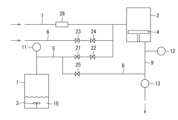
- FIG. 1 is a schematic diagram illustrating an example of a film forming apparatus according to the present disclosure.
- FIG. 2 is a graph showing the evaporation rates of the raw material compounds in the examples.
- FIG. 3 is a graph showing the evaporation rate of the raw material compound in the comparative example.
- the method for producing a thin film according to the present disclosure includes: vaporizing a raw material liquid containing a raw material compound in an evaporator; Introducing the raw material compound vaporized in the vaporization step into a film formation chamber and forming a film on a substrate; and further comprising discharging the gas phase portion of the evaporator.
- the method for producing a thin film according to the present disclosure can be carried out using the film forming apparatus according to the present disclosure.
- an evaporator for vaporizing a raw material liquid containing a raw material compound a discharge mechanism for discharging a gas phase portion of the evaporator; a film forming chamber for forming a film on a substrate,
- the evaporator includes a movement mechanism for moving the raw material liquid containing the raw material compound.
- the film forming apparatus of the present disclosure has an evaporator 1 and a film forming chamber 2, and the evaporator 1 is equipped with an agitator (movement mechanism) 3.
- the film forming chamber 2 is equipped with a film forming table 4.
- the evaporator 1 and the film forming chamber 2 are connected by a main line (connecting part) 5.
- a line 9 for discharging gas after film formation is connected to the film forming chamber 2.
- a line 6 for supplying a reactive gas and a line 7 for supplying a carrier gas are connected to the main line 5.
- the main line 5 and the line 9 are connected by a line (discharge mechanism) 8.
- the line 8 bypasses the main line 5 and the line 9, and enables the gas in the gas phase in the evaporator 1 to be discharged outside the film forming apparatus without passing through the film forming chamber 2.
- the evaporator 1 contains a raw material liquid 15, and the raw material compound vaporized in the evaporator passes through the main line 5, is mixed with the reactive gas supplied from the line 6 and the carrier gas supplied from the line 7, and is transferred to the film forming chamber 2. After reaction, each gas is exhausted from the film-forming chamber 2 through line 9. On the other hand, the gas phase of the evaporator 1 can be exhausted from line 9 without passing through the film-forming chamber 2 by passing through line 8.
- a pump 11 is provided near the evaporator 1 on the main line 5.
- a pump 12 is provided near the film-forming chamber 2 on the line 9, and a pump 13 is provided downstream of the connection of the line 9 with the line 8.
- Valves 21 and 22 for adjusting the gas flow rate are provided on the main line 5.
- Valves 23 and 24 for adjusting the gas flow rate are provided on the line 6.
- a valve 25 for adjusting the gas flow rate is provided on the line 8.
- a mass flow controller (hereinafter also referred to as "MFC") 26 for adjusting the gas flow rate is provided on the line 7.
- the film forming method of the present disclosure includes a step of vaporizing a raw material liquid containing a raw material compound in an evaporator (hereinafter also referred to as "step A").
- the above raw material compounds are organometallic compounds.
- the metal atoms in the organometallic compounds include transition metals such as cobalt, nickel, copper, vanadium, niobium, tantalum, chromium, molybdenum, and tungsten.
- the metal atom is cobalt or tungsten.
- cobalt or tungsten as the metal atom, for example, when a film is formed on copper wiring, breakage of the copper wiring can be prevented.
- the organic ligands in the organometallic compounds include, for example, alkyl, alkenyl, cycloalkyl, aryl, alkynyl, alkylimino, amino, dialkylaminoalkyl, monoalkylamino, dialkylamino, diamine, di(silyl-alkyl)amino, di(alkyl-silyl)amino, disilylamino, alkoxy, alkoxyalkyl, hydrazide, phosphide, nitrile, dialkylaminoalkoxy, alkoxyalkyldialkylamino, siloxy, diketonate, cyclopentadienyl, silyl, pyrazolate, guanidinate, phosphoguanidinate, amidinate, phosphoamidinate, ketoiminate, diketiminate, carbonyl, and the like.
- the organic ligand is a carbonyl, a cyclopentadienyl, or an amidinate.
- the organometallic compound is It is.
- the above raw material compounds may be used alone or in combination of two or more.
- the raw material compound is vaporized in evaporator 1.
- the above raw material liquid may contain impurities.
- the above impurities include decomposition products produced by the decomposition of the above raw material compounds, water, etc.
- the raw material liquid consists essentially of the raw material compound.
- FIG. 1 there is only one evaporator 1, but there may be two or more, for example when two or more kinds of raw material compounds are used.
- the evaporator 1 is equipped with a motion mechanism 3.
- the motion mechanism 3 is a mechanism that moves the raw liquid present in the evaporator 1. This motion increases the contact area between the raw liquid and the gas phase in the evaporator 1.
- the raw material liquid in the evaporator By moving the raw material liquid in the evaporator and increasing the contact area with the gas phase, the evaporation rate of the raw material liquid increases, and the partial pressure of the raw material compound in the gas phase in the evaporator increases. In other words, the raw material compound can reach saturated vapor pressure in the gas phase in the evaporator sooner. By shortening the time to reach saturated vapor pressure, film formation by ALD is stabilized. In addition, the time between film formation cycles can be shortened, improving the film formation speed.
- the movement mechanism 3 is not particularly limited as long as it can move the raw liquid.
- examples of the movement mechanism include a stirring mechanism and a vibration mechanism.
- stirring mechanism examples include a mechanism that rotates a stirring member in the liquid, a mechanism that rotates the container itself, a mechanism that sprays raw compound into the liquid, etc.
- the stirring mechanism is a mechanism that rotates a stirring member immersed in the liquid.
- stirring members include paddle-type, tumbler-type, and ribbon-type blenders.
- Examples of the vibration mechanism include a mechanism that irradiates ultrasonic waves to vibrate the liquid, a mechanism that vibrates the container itself, etc.
- the contact area between the raw liquid and the gas phase in the evaporator may be preferably 1.1 times or more, more preferably 1.5 times or more, even more preferably 2.0 times or more, and even more preferably 3.0 times or more, compared to when there is no movement of the raw liquid.
- the above contact area may be preferably 100 times or less, more preferably 50 times or less, compared to when there is no movement of the raw liquid.
- the contact area between the raw liquid and the gas phase can be calculated by simulation using fluid analysis software.
- the temperature inside the evaporator and the temperature of the raw material liquid can be made relatively low.
- the temperature of the raw material liquid in the evaporator 1 is preferably 400°C or less, and more preferably 350°C or less. By using such a relatively low temperature, decomposition of undesirable raw material compounds can be suppressed, and the incorporation of impurities into the formed film can be prevented. It is also excellent in energy efficiency.
- the temperature of the raw material liquid can be, for example, 150°C or more, and preferably 200°C or more.
- the raw material compound may be heated by heating the evaporator from the outside with a heater or the like, or by a heater or the like provided inside the evaporator.
- the raw material liquid may be heated by blowing a heated medium, such as a carrier gas, into the raw material liquid, or the raw material liquid heated externally may be introduced into the evaporator.
- the air pressure inside the evaporator 1 can be between 100 Pa and 1.5 kPa.
- the film formation method of the present disclosure includes a step of introducing the precursor compound vaporized in the step A into a film formation chamber (hereinafter also referred to as "step B").
- the raw material compound introduced into the deposition chamber is deposited on a substrate placed inside the deposition chamber, forming a film of the raw material compound.
- the gaseous raw material compound produced in the evaporator 1 is transferred to the film-forming chamber 2 via the main line 5.
- the gaseous raw material compound remaining in the film-forming chamber 2 is discharged outside the system via line 9.
- the main line 5 may have a valve for adjusting the pressure inside the evaporator 1 or for adjusting the flow rate of the raw material compound to the film formation chamber 2.
- the main line 5 has valves 21 and 22.
- the main line 5 may be connected to a line for transporting a carrier gas, a line for transporting a reactive gas, etc.
- the main line 5 is connected to a line 6 for transporting a reactive gas and a line 7 for transporting a carrier gas.
- Line 7 may have a mechanism for controlling the flow rate of the carrier gas.
- Line 7 may have a mass flow controller for controlling the flow rate of the carrier gas.
- line 7 has a mass flow controller 26.
- the raw material compound gas and the carrier gas are mixed in the main line 5. Note that, although line 7 is connected to the main line 5 in FIG. 1, it may also be connected to the evaporator 1, and the raw material compound and the carrier gas may be mixed in the evaporator.
- Carrier gases include inert gases such as nitrogen and rare gases, and preferably nitrogen or argon gas is used.
- the main line 5 may have a heating mechanism.
- the heating mechanism may be a heater arranged around the piping, typically a jacket heater.
- the heating is preferably performed at a temperature at which the partial pressure of the raw material compound in the evaporator 1 is substantially the same as the partial pressure of the raw material compound in the portion connecting the evaporator 1 and the film-forming chamber 2 (i.e., main line 5).
- the partial pressure of the raw material compound in the evaporator 1 and the part connecting the evaporator 1 and the deposition chamber 2 being substantially the same means that the difference between the two partial pressures is within 50 Pa.
- the difference between the partial pressure of the raw material compound in the evaporator 1 and the part connecting the evaporator 1 and the deposition chamber 2 is preferably within 30 Pa, more preferably within 10 Pa, and even more preferably within 5 Pa.
- the film formation method of the present disclosure may include a step of introducing a reactive gas into the film formation chamber (hereinafter also referred to as “step C”).
- the reactive gas introduced into the deposition chamber reacts with the raw material compounds deposited on the substrate, reducing them. This forms a metal film on the substrate.
- the reactive gas is introduced into the deposition chamber 2 from line 6 via the main line 5. After reaction in the deposition chamber 2, the reactive gas is discharged from the system through line 9.
- Line 6 may have a mechanism for controlling the flow rate of the reactive gas.
- line 6 has valves 23, 24 for controlling the flow rate of the reactive gas.
- the reactive gas is mixed with the carrier gas in main line 5.
- line 7 is connected to main line 5 in FIG. 1, it may also be connected to deposition chamber 2 to introduce the reactive gas directly into deposition chamber 2.
- the film forming method of the present disclosure may include a step of removing the gas phase portion of the evaporator (hereinafter also referred to as "step D").
- step D by removing the gas phase part of the evaporator, the concentration of impurities in the evaporator 1 decreases, the vapor pressure of the raw material compounds becomes stable, and stable film formation becomes possible. In addition, it is possible to suppress impurities from being mixed into the film.
- the gas phase of the evaporator 1 contains impurities.
- the gas phase containing the impurities is discharged to the outside of the system through line 8 connected to the main line 5.
- Line 8 bypasses between lines 5 and 9. This allows the gas in the vapor phase in evaporator 1 to be discharged outside the deposition apparatus without passing through deposition chamber 2.
- Line 8 has a valve 25 for turning the gas discharge on and off.
- Step D is performed before step B. Specifically, step D is performed within 1 minute, preferably within 30 seconds, more preferably within 20 seconds, and even more preferably within 10 seconds before step B.
- Step D may be performed simultaneously with step C, or may be performed separately. When step D is performed simultaneously with step C, only a portion of step D or step C may be performed simultaneously with the other step.
- the method for producing a thin film disclosed herein is a cycle in which step B is performed while step A is being performed, and then step C is performed, and after step B, step D is performed during the next step B.
- Step D may be performed in parallel with step C.
- step (i) In step (i), a source compound is introduced and deposited on a substrate to form a film of the source compound.
- the above substrate is usually placed on a deposition table installed in deposition chamber 2 before the introduction of the raw material compound.
- the material constituting the substrate is not particularly limited, but examples include metals such as copper, silver, gold, platinum, nickel, palladium, and aluminum; silicon; ceramics such as indium arsenide, indium gallium arsenide, silicon oxide, silicon nitride, silicon carbide, titanium nitride, tantalum oxide, tantalum nitride, titanium oxide, titanium nitride, ruthenium oxide, zirconium oxide, hafnium oxide, lanthanum oxide, and gallium nitride; and glass.
- metals such as copper, silver, gold, platinum, nickel, palladium, and aluminum
- silicon ceramics such as indium arsenide, indium gallium arsenide, silicon oxide, silicon nitride, silicon carbide, titanium nitride, tantalum oxide, tantalum nitride, titanium oxide, titanium nitride, ruthenium oxide, zirconium oxide, hafnium oxide, lanthanum oxide, and gall
- the material constituting the substrate is copper, silver, gold, platinum, nickel, palladium, or aluminum, and is preferably copper.
- the shape of the substrate is not particularly limited and may be plate-like, rod-like, spherical, layer-like, fibrous, scale-like, etc.
- the substrate may be in the form of a layer provided on a substrate, for example, wiring on a wiring board.
- the temperature of the substrate when the raw material compound is deposited on the substrate may be, for example, 20 to 600°C, preferably 50 to 500°C, more preferably 100 to 450°C, and even more preferably 100 to 400°C.
- step (ii) In step (ii), the source compound remaining in the film forming chamber 2 is exhausted.
- Evacuation methods include purging the system with an inert gas such as nitrogen or argon, evacuating the system by reducing the pressure, or a combination of these.
- an inert gas such as nitrogen or argon
- step (iii) In step (iii), a reactive gas is introduced into the film formation chamber 2, and the reactive gas reacts with the raw material compound deposited on the substrate, thereby reducing the raw material compound to form a metal film.
- the reactive gas is not particularly limited as long as it can react with the raw material compound, and examples include hydrogen, oxygen, formic acid, hydrogen chloride, hydrogen bromide, hydrogen iodide, monochlorosilane, dichlorosilane, trichlorosilane, tetrachlorosilane, boron trichloride, boron tribromide, methyl iodide, methyl bromide, etc.
- the temperature of the substrate when the reactive gas is introduced into the deposition chamber 2 may be, for example, 20 to 600°C, preferably 50 to 500°C, more preferably 100 to 450°C, and even more preferably 100 to 400°C.
- step (iv) In step (iv), the unreacted reactive gases and by-product gases are exhausted.
- Evacuation methods include purging the system with an inert gas such as nitrogen or argon, evacuating the system by reducing the pressure, or a combination of these.
- an inert gas such as nitrogen or argon
- Line 9 may have an exhaust valve for adjusting the exhaust flow rate or for adjusting the pressure in the deposition chamber 2.
- steps (i) to (iv) form one cycle, which can be repeated multiple times depending on the desired film thickness.
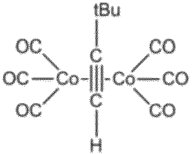
- the process conditions are as follows: Starting compound: (3,3-dimethyl-1-butyne) dicobalt hexacarbonyl: Raw material compound gas flow rate: 0.003 scc (Standard Cubic Sentimeters)/cycle x 5 cycles Reactive gas: hydrogen Reactive gas flow rate: 14 scc/cycle x 3 cycles Carrier gas: nitrogen Carrier gas flow rate: 5 ccpm Evaporator set temperature: 70°C Temperature setting in film formation chamber: 200° C.
- ⁇ Common Process> The raw material compound as the raw material liquid is heated to a set temperature while being stirred. At the same time, the film formation chamber is heated to a set temperature. A carrier gas is supplied at a set flow rate (5 sccm) by a mass flow controller. The valve 25 is opened for 10 seconds to remove the gas phase from the evaporator. Then, the valve 25 is closed.
- Example Process After the above common process, the following steps are performed. (1) Repeat the following five times. Open valve 21 ⁇ close valve 21 after 1 second ⁇ open valve 22 after 0.75 seconds ⁇ close valve 22 after 1 second. (2) 0.25 seconds after (1), valve 25 is opened, and 2 seconds after (1), valve 25 is closed. (3) Two seconds after (1), repeat the following three times. Open valve 23 -> close valve 23 after 1 second -> open valve 24 after 0.75 seconds -> close valve 24 after 1 second (4) (3) and then return to (1) again 5 seconds later.
- Comparative Example Process (1) Repeat the following five times. Open valve 21 ⁇ close valve 21 after 1 second ⁇ open valve 22 after 0.75 seconds ⁇ close valve 22 after 1 second (2) (1) The following is repeated three times two seconds after (1). Open valve 23 ⁇ close valve 23 after 1 second ⁇ open valve 24 after 0.75 seconds ⁇ close valve 24 after 1 second. (3) Return to (1) again 5 seconds after (2).
- the small fluctuations near the saturated vapor pressure in Fig. 2 are pressure fluctuations during pulse supply in Example Process (1). After the pulse supply is completed, impurities due to thermal decomposition are removed by evacuating to about 100 Pa in Example Process (2). Thereafter, the evaporation of the raw material proceeds quickly by providing a raw material stirring mechanism, and after the reactive gas is supplied in Example Process (3), the raw material vapor pressure recovers to near the saturated vapor pressure, and when the raw material is supplied again in pulse supply in Example Process (4), it can be supplied at a constant pressure. This confirmed that a stable ALD process can be performed.
- the evaporation of the raw material proceeds quickly due to the stirring mechanism, but the decomposition products accumulate in the container because the impurities are not removed by vacuuming.
- the pressure inside the container greatly exceeds the saturated vapor pressure, and the pressure during the pulse supply of the raw material (small fluctuation part) continues to rise with each cycle. This means that the raw material cannot be supplied at a constant pressure, and the impurity ratio in the raw material also continues to rise, confirming that a stable ALD process cannot be performed.
- the film formation method disclosed herein can efficiently form thin films with high purity, and can therefore be used for a variety of applications, such as the manufacture of circuit boards.
Landscapes
- Chemical & Material Sciences (AREA)
- General Chemical & Material Sciences (AREA)
- Chemical Kinetics & Catalysis (AREA)
- Engineering & Computer Science (AREA)
- Materials Engineering (AREA)
- Mechanical Engineering (AREA)
- Metallurgy (AREA)
- Organic Chemistry (AREA)
- Chemical Vapour Deposition (AREA)
- Physical Vapour Deposition (AREA)
Abstract
Description
[1] 蒸発器において、原料化合物を含む原料液体を気化させること、
前記工程において気化された原料化合物を、成膜室に導入すること、
基材上に薄膜を形成すること、
を含む、原子層堆積法による薄膜の製造方法であって、
前記蒸発器の気相部を排出することを含む、薄膜の製造方法。
[2] 前記蒸発器において前記原料液体を、気相との接触面積が増加するように運動させることを含む、上記[1]に記載の薄膜の製造方法。
[3] 前記原料液体の運動は、撹拌機構により撹拌されることにより生じる、上記[2]に記載の薄膜の製造方法。
[4] 前記原料液体の前記気相との接触面積は、前記運動がない場合の接触面積に対し、1.1倍以上である、上記[2]又は[3]に記載の薄膜の製造方法。
[5] 前記蒸発器内の原料液体の温度は、400℃以下である、上記[1]~[4]のいずれか1項に記載の薄膜の製造方法。
[6] 前記蒸発器と前記成膜室とを連結する部分における、前記原料化合物の分圧は、前記蒸発器における前記原料化合物の分圧と実質的に同じである、上記[1]~[5]のいずれか1項に記載の薄膜の製造方法。
[7] 前記原料化合物は、金属カルボニル錯体、金属メタロセン錯体、又は金属アミジネート錯体である、上記[1]~[6]のいずれか1項に記載の薄膜の製造方法。
[8] 前記金属は、Co又はWである、上記[7]に記載の薄膜の製造方法。
[9] 前記原料化合物は、
[10] 前記気相部は、原料化合物の分解物を含む、上記[1]~[9]のいずれか1項に記載の薄膜の製造方法。
[11] 前記基材は、銅基材である、上記[1]~[10]のいずれか1項に記載の薄膜の製造方法。
[12] 工程A蒸発器において、原料化合物を含む原料液体を気化させること、
工程B前記蒸発器において気化された原料化合物を、成膜室に導入すること、
工程C反応性ガスを成膜室に導入すること、
工程D前記蒸発器の気相部を排出すること
を含み、
工程Aを行いながら、工程B、次いで、工程Cを行うサイクルであって、工程Bの後、次回の工程Bの間に、工程Dを行うサイクルを実行する、上記[1]~[11]のいずれか1項に記載の薄膜の製造方法。
[13] 工程(i)成膜室内に、原料化合物を導入することにより、原料化合物を基材上に堆積させ、原料化合物の膜を形成すること、
工程(ii)成膜室内に残留する原料化合物を排気すること、
工程(iii)成膜室内に反応性ガスを導入することにより、基材上に堆積した原料化合物と反応ガスを反応させ、原料化合物を還元し、膜を形成すること、
工程(iv)成膜室内の未反応の反応性ガス及び副生したガスを排気すること
を含む、上記[1]~[12]のいずれか1項に記載の薄膜の製造方法。
[14] 工程A:蒸発器において、原料化合物を含む原料液体を気化させること、
工程B:前記蒸発器において気化された原料化合物を、成膜室に導入すること、
工程C:反応性ガスを成膜室に導入すること、
工程D:前記蒸発器の気相部を排出すること
を含み、
工程Aを行いながら、工程B、次いで、工程Cを行うサイクルであって、工程Bの後、次回の工程Bの間に、工程Dを行うサイクルを実行し、
前記原料化合物は、
前記蒸発器において前記原料液体を、気相との接触面積が増加するように、撹拌機構により撹拌することにより運動させることを含み、
前記蒸発器内の原料液体の温度は、350℃以下であり、
前記気相部は、原料化合物の分解物を含み、
前記基材は、銅基材である、
上記[1]~[13]のいずれか1項に記載の薄膜の製造方法。
[15] 原料化合物を含む原料液体を気化させる蒸発器と、
前記蒸発器の気相を排出する排出機構と、
基材上に原子層堆積法により成膜する成膜室と、
を有する成膜装置。
[16] 前記蒸発器は、前記原料化合物を含む原料液体を運動させる運動機構を備える、上記[15]に記載の成膜装置。
[17] 前記運動機構は、撹拌機構である、上記[15]又は[16]に記載の成膜装置。
[18] 前記蒸発器内の前記原料液体の温度は、400℃以下である、上記[15]~[17]のいずれか1項に記載の成膜装置。
[19] さらに、前記蒸発器と前記成膜室を連結する連結部を有し、前記蒸発器における前記原料化合物の分圧は、前記蒸発器における前記原料化合物の分圧と実質的に同じである、上記[15]~[18]のいずれか1項に記載の成膜装置。
蒸発器において原料化合物を含む原料液体を気化させること、
上記気化工程において気化された原料化合物を、成膜室に導入し、基材上に成膜すること、
を含み、さらに上記蒸発器の気相部を排出することを含むことを特徴とする。
原料化合物を含む原料液体を気化させる蒸発器と、
上記蒸発器の気相部を排出する排出機構と、
基材上に成膜する成膜室と
を有し、
上記蒸発器は、上記原料化合物を含む原料液体を運動させる運動機構を備える。
本開示の成膜方法は、蒸発器において原料化合物を含む原料液体を気化させる工程(以下、「工程A」ともいう)を含む。
本開示の成膜方法は、前記工程Aにおいて気化された原料化合物を、成膜室に導入する工程(以下、「工程B」ともいう)を含む。
本開示の成膜方法は、反応性ガスを成膜室に導入する工程(以下、「工程C」ともいう)を含み得る。
本開示の成膜方法は、蒸発器の気相部を除去する工程(以下、「工程D」ともいう)を含み得る。
工程(i)では、原料化合物が導入され、基材上に原料化合物が堆積し、原料化合物の膜が形成される。
工程(ii)では、成膜室2内に残留する原料化合物を排気する
工程(iii)では、成膜室2内に反応性ガスが導入され、基材上に堆積した原料化合物と反応性ガスが反応して、原料化合物が還元されることにより、金属膜が形成される。
工程(iv)では、未反応の反応性ガス及び副生したガスを排気する。
原料化合物:(3,3-ジメチル-1-ブチン)ジコバルトヘキサカルボニル:
反応性ガス:水素 反応性ガス流量:14scc/サイクル×3サイクル
キャリアガス:窒素
キャリアガス流量:5ccpm
蒸発器の設定温度:70℃
成膜室の設定温度:200℃
原料液体としての原料化合物を、攪拌しながら、設定温度にて加熱する。同時に、成膜室を設定温度に加熱する。キャリアガスをマスフローコントローラーにより設定流量(5sccm)にて供給する。バルブ25を10秒開けて、蒸発器の気相を除去する。その後、バルブ25を閉じる。
上記の共通プロセスの後、下記の工程を行う。
(1)下記を5回繰り返す。
バルブ21を開ける→1秒後にバルブ21を閉じる→0.75秒後にバルブ22開ける→1秒後にバルブ22を閉じる。
(2)(1)の0.25秒後にバルブ25を開け、2秒後にバルブ25を閉じる。
(3)(1)の2秒後に下記を3回繰り返す。
バルブ23を開ける→1秒後にバルブ23を閉じる→0.75秒後にバルブ24を開ける
→1秒後にバルブ24を閉じる
(4)(3)の5秒後に再度(1)に戻る。
(1)下記を5回繰り返す。
バルブ21を開ける→1秒後にバルブ21を閉じる→0.75秒後にバルブ22を開ける→1秒後にバルブ22を閉じる
(2)(1)の2秒後に下記を3回繰り返す。
バルブ23を開ける→1秒後にバルブ23を閉じる→0.75秒後にバルブ24を開ける→1秒後にバルブ24を閉じる。
(3)(2)の5秒後に再度(1)に戻る。
一方、比較例プロセスにおいては、撹拌機構により速やかに原料の蒸発は進むものの、真空引きによる不純物の除去がないために、分解物が容器内に蓄積する。図3に示すように、容器内圧力は飽和蒸気圧を大きく超え、原料のパルス供給時(小刻みな変動部分)の圧力はサイクルを重ねるごとに上昇し続けている。これは、一定圧力にて原料が供給できていないことに加え、原料中の不純物比率も上がり続けることを意味しており、安定的なALDプロセスを行うことができていないことが確認された。
2…成膜室
3…攪拌機
4…成膜台
5…メインライン(配管)
6…ライン
7…ライン
8…ライン
9…ライン
11…ポンプ
12…ポンプ
13…ポンプ
15…原料液体
21,22…バルブ
23,24…バルブ
25…バルブ
26…マスフローコントローラー
Claims (19)
- 蒸発器において、原料化合物を含む原料液体を気化させること、
前記工程において気化された原料化合物を、成膜室に導入すること、
基材上に薄膜を形成すること、
を含む、原子層堆積法による薄膜の製造方法であって、
前記蒸発器の気相部を排出することを含む、薄膜の製造方法。 - 前記蒸発器において前記原料液体を、気相との接触面積が増加するように運動させることを含む、請求項1に記載の薄膜の製造方法。
- 前記原料液体の運動は、撹拌機構により撹拌されることにより生じる、請求項2に記載の薄膜の製造方法。
- 前記原料液体の前記気相との接触面積は、前記運動がない場合の接触面積に対し、1.1倍以上である、請求項2に記載の薄膜の製造方法。
- 前記蒸発器内の原料液体の温度は、400℃以下である、請求項1に記載の薄膜の製造方法。
- 前記蒸発器と前記成膜室とを連結する部分における、前記原料化合物の分圧は、前記蒸発器における前記原料化合物の分圧と実質的に同じである、請求項1に記載の薄膜の製造方法。
- 前記原料化合物は、金属カルボニル錯体、金属メタロセン錯体、又は金属アミジネート錯体である、請求項1に記載の薄膜の製造方法。
- 前記金属は、Co又はWである、請求項7に記載の薄膜の製造方法。
- 前記原料化合物は、
- 前記気相部は、原料化合物の分解物を含む、請求項1に記載の薄膜の製造方法。
- 前記基材は、銅基材である、請求項1に記載の薄膜の製造方法。
- 工程A:蒸発器において、原料化合物を含む原料液体を気化させること、
工程B:前記蒸発器において気化された原料化合物を、成膜室に導入すること、
工程C:反応性ガスを成膜室に導入すること、
工程D:前記蒸発器の気相部を排出すること
を含み、
工程Aを行いながら、工程B、次いで、工程Cを行うサイクルであって、工程Bの後、次回の工程Bの間に、工程Dを行うサイクルを実行する、請求項1に記載の薄膜の製造方法。 - 工程(i)成膜室内に、原料化合物を導入することにより、原料化合物を基材上に堆積させ、原料化合物の膜を形成すること、
工程(ii)成膜室内に残留する原料化合物を排気すること、
工程(iii)成膜室内に反応性ガスを導入することにより、基材上に堆積した原料化合物と反応ガスを反応させ、原料化合物を還元し、膜を形成すること、
工程(iv)成膜室内の未反応の反応性ガス及び副生したガスを排気すること
を含む、請求項1に記載の薄膜の製造方法。 - 工程A:蒸発器において、原料化合物を含む原料液体を気化させること、
工程B:前記蒸発器において気化された原料化合物を、成膜室に導入すること、
工程C:反応性ガスを成膜室に導入すること、
工程D:前記蒸発器の気相部を排出すること
を含み、
工程Aを行いながら、工程B、次いで、工程Cを行うサイクルであって、工程Bの後、次回の工程Bの間に、工程Dを行うサイクルを実行し、
前記原料化合物は、

前記蒸発器において前記原料液体を、気相との接触面積が増加するように、撹拌機構により撹拌することにより運動させることを含み、
前記蒸発器内の原料液体の温度は、350℃以下であり、
前記気相部は、原料化合物の分解物を含み、
前記基材は、銅基材である、
請求項1に記載の薄膜の製造方法。 - 原料化合物を含む原料液体を気化させる蒸発器と、
前記蒸発器の気相を排出する排出機構と、
基材上に原子層堆積法により成膜する成膜室と、
を有する成膜装置。 - 前記蒸発器は、前記原料化合物を含む原料液体を運動させる運動機構を備える、請求項15に記載の成膜装置。
- 前記運動機構は、撹拌機構である、請求項15に記載の成膜装置。
- 前記蒸発器内の前記原料液体の温度は、400℃以下である、請求項15に記載の成膜装置。
- さらに、前記蒸発器と前記成膜室を連結する連結部を有し、前記蒸発器における前記原料化合物の分圧は、前記蒸発器における前記原料化合物の分圧と実質的に同じである、請求項15に記載の成膜装置。
Priority Applications (4)
| Application Number | Priority Date | Filing Date | Title |
|---|---|---|---|
| CN202480013581.4A CN120731291A (zh) | 2023-02-20 | 2024-02-19 | 利用原子层沉积法的成膜方法 |
| KR1020257027529A KR20250136874A (ko) | 2023-02-20 | 2024-02-19 | 원자층 퇴적법에 의한 성막 방법 |
| EP24760307.9A EP4512925A4 (en) | 2023-02-20 | 2024-02-19 | FILM DEPOSIT METHOD USING ATOMIC LAYER DEPOSIT |
| US19/302,630 US20250369116A1 (en) | 2023-02-20 | 2025-08-18 | Film deposition method by atomic layer deposition |
Applications Claiming Priority (2)
| Application Number | Priority Date | Filing Date | Title |
|---|---|---|---|
| JP2023024296A JP7541305B1 (ja) | 2023-02-20 | 2023-02-20 | 原子層堆積法による成膜方法 |
| JP2023-024296 | 2023-02-20 |
Related Child Applications (1)
| Application Number | Title | Priority Date | Filing Date |
|---|---|---|---|
| US19/302,630 Continuation US20250369116A1 (en) | 2023-02-20 | 2025-08-18 | Film deposition method by atomic layer deposition |
Publications (1)
| Publication Number | Publication Date |
|---|---|
| WO2024177008A1 true WO2024177008A1 (ja) | 2024-08-29 |
Family
ID=92499114
Family Applications (1)
| Application Number | Title | Priority Date | Filing Date |
|---|---|---|---|
| PCT/JP2024/005773 Ceased WO2024177008A1 (ja) | 2023-02-20 | 2024-02-19 | 原子層堆積法による成膜方法 |
Country Status (7)
| Country | Link |
|---|---|
| US (1) | US20250369116A1 (ja) |
| EP (1) | EP4512925A4 (ja) |
| JP (1) | JP7541305B1 (ja) |
| KR (1) | KR20250136874A (ja) |
| CN (1) | CN120731291A (ja) |
| TW (1) | TW202438716A (ja) |
| WO (1) | WO2024177008A1 (ja) |
Families Citing this family (1)
| Publication number | Priority date | Publication date | Assignee | Title |
|---|---|---|---|---|
| KR20260030908A (ko) * | 2023-08-24 | 2026-03-06 | 다이킨 고교 가부시키가이샤 | 금속 착체 |
Citations (6)
| Publication number | Priority date | Publication date | Assignee | Title |
|---|---|---|---|---|
| JPH09217175A (ja) * | 1996-02-15 | 1997-08-19 | Anelva Corp | 液体原料ガス供給機構とこれを含む表面処理装置 |
| JP2007266185A (ja) * | 2006-03-28 | 2007-10-11 | Hitachi Kokusai Electric Inc | 基板処理装置及び半導体装置の製造方法 |
| JP2010508660A (ja) * | 2006-10-26 | 2010-03-18 | アプライド マテリアルズ インコーポレイテッド | 温度制御マルチガス分配アセンブリ |
| JP2010212390A (ja) * | 2009-03-10 | 2010-09-24 | Hitachi Kokusai Electric Inc | 基板処理装置 |
| JP2019143248A (ja) * | 2015-05-13 | 2019-08-29 | バーサム マテリアルズ ユーエス,リミティド ライアビリティ カンパニー | 堆積プロセスにおける化学前駆体のための容器 |
| JP2021036068A (ja) | 2019-08-30 | 2021-03-04 | 株式会社明電舎 | 原子層堆積方法 |
Family Cites Families (3)
| Publication number | Priority date | Publication date | Assignee | Title |
|---|---|---|---|---|
| US7186385B2 (en) * | 2002-07-17 | 2007-03-06 | Applied Materials, Inc. | Apparatus for providing gas to a processing chamber |
| KR101639732B1 (ko) * | 2009-12-16 | 2016-07-15 | 주성엔지니어링(주) | 박막 증착 시스템 및 이를 이용한 박막 증착 방법 |
| JP2016134569A (ja) * | 2015-01-21 | 2016-07-25 | 株式会社東芝 | 半導体製造装置 |
-
2023
- 2023-02-20 JP JP2023024296A patent/JP7541305B1/ja active Active
-
2024
- 2024-02-19 KR KR1020257027529A patent/KR20250136874A/ko active Pending
- 2024-02-19 CN CN202480013581.4A patent/CN120731291A/zh active Pending
- 2024-02-19 TW TW113105844A patent/TW202438716A/zh unknown
- 2024-02-19 EP EP24760307.9A patent/EP4512925A4/en active Pending
- 2024-02-19 WO PCT/JP2024/005773 patent/WO2024177008A1/ja not_active Ceased
-
2025
- 2025-08-18 US US19/302,630 patent/US20250369116A1/en active Pending
Patent Citations (6)
| Publication number | Priority date | Publication date | Assignee | Title |
|---|---|---|---|---|
| JPH09217175A (ja) * | 1996-02-15 | 1997-08-19 | Anelva Corp | 液体原料ガス供給機構とこれを含む表面処理装置 |
| JP2007266185A (ja) * | 2006-03-28 | 2007-10-11 | Hitachi Kokusai Electric Inc | 基板処理装置及び半導体装置の製造方法 |
| JP2010508660A (ja) * | 2006-10-26 | 2010-03-18 | アプライド マテリアルズ インコーポレイテッド | 温度制御マルチガス分配アセンブリ |
| JP2010212390A (ja) * | 2009-03-10 | 2010-09-24 | Hitachi Kokusai Electric Inc | 基板処理装置 |
| JP2019143248A (ja) * | 2015-05-13 | 2019-08-29 | バーサム マテリアルズ ユーエス,リミティド ライアビリティ カンパニー | 堆積プロセスにおける化学前駆体のための容器 |
| JP2021036068A (ja) | 2019-08-30 | 2021-03-04 | 株式会社明電舎 | 原子層堆積方法 |
Non-Patent Citations (1)
| Title |
|---|
| See also references of EP4512925A4 |
Also Published As
| Publication number | Publication date |
|---|---|
| JP7541305B1 (ja) | 2024-08-28 |
| US20250369116A1 (en) | 2025-12-04 |
| TW202438716A (zh) | 2024-10-01 |
| JP2024120193A (ja) | 2024-09-05 |
| KR20250136874A (ko) | 2025-09-16 |
| EP4512925A4 (en) | 2026-02-25 |
| EP4512925A1 (en) | 2025-02-26 |
| CN120731291A (zh) | 2025-09-30 |
Similar Documents
| Publication | Publication Date | Title |
|---|---|---|
| TWI655309B (zh) | 來自金屬脒鹽前驅物與鋁前驅物的金屬鋁合金膜 | |
| JP3875491B2 (ja) | ルテニウムまたは酸化ルテニウムを化学蒸着するための前駆物質の化学的性質 | |
| US5908947A (en) | Difunctional amino precursors for the deposition of films comprising metals | |
| JP4713041B2 (ja) | 遷移金属窒化物薄膜の堆積方法 | |
| KR100406534B1 (ko) | 루테늄 박막의 제조 방법 | |
| US20050136657A1 (en) | Film-formation method for semiconductor process | |
| JP2003517731A (ja) | 原子層堆積中の寄生化学気相成長を最小限に抑える装置と方法 | |
| JPH0649944B2 (ja) | 銅薄膜の選択蒸着の可能な銅錯体と、その蒸着法ならびに薄膜の選択エッチング法 | |
| WO2004007795A1 (ja) | 半導体処理用の成膜方法 | |
| JP6193260B2 (ja) | ニッケル含有膜堆積用ニッケルアリルアミジナート前駆体 | |
| WO2007117898A1 (en) | System for introducing a precursor gas to a vapor deposition system | |
| JP4965260B2 (ja) | シーケンシャル流量堆積を使用して金属層を堆積させる方法。 | |
| US20250369116A1 (en) | Film deposition method by atomic layer deposition | |
| KR100474565B1 (ko) | 소스 가스 공급 방법 및 장치 | |
| JP2005171291A (ja) | チタン含有薄膜およびその製造方法 | |
| WO2021158633A2 (en) | Precursors for high-temperature deposition of silicon-containing films | |
| JP5826698B2 (ja) | Ni膜の形成方法 | |
| JP2006096675A (ja) | 新規なアミノジシランおよび炭窒化珪素膜の形成方法 | |
| JP4338246B2 (ja) | Cu−CVDプロセス用原料とCu−CVD装置 | |
| TWI557256B (zh) | 來自金屬pcai前驅物與鋁前驅物的金屬鋁合金膜 | |
| JP2009228113A (ja) | ルテニウム膜の成膜方法 | |
| WO2025041857A1 (ja) | 薄膜の製造方法 | |
| JP3251990B2 (ja) | Al若しくはAl合金の成膜方法 | |
| JP2025031690A (ja) | 薄膜の製造方法 | |
| KR100304821B1 (ko) | Pt계 박막의 제조방법 |
Legal Events
| Date | Code | Title | Description |
|---|---|---|---|
| 121 | Ep: the epo has been informed by wipo that ep was designated in this application |
Ref document number: 24760307 Country of ref document: EP Kind code of ref document: A1 |
|
| WWE | Wipo information: entry into national phase |
Ref document number: 2024760307 Country of ref document: EP |
|
| ENP | Entry into the national phase |
Ref document number: 2024760307 Country of ref document: EP Effective date: 20241120 |
|
| ENP | Entry into the national phase |
Ref document number: 1020257027529 Country of ref document: KR Free format text: ST27 STATUS EVENT CODE: A-0-1-A10-A15-NAP-PA0105 (AS PROVIDED BY THE NATIONAL OFFICE) |
|
| WWE | Wipo information: entry into national phase |
Ref document number: 1020257027529 Country of ref document: KR Ref document number: 202480013581.4 Country of ref document: CN |
|
| NENP | Non-entry into the national phase |
Ref country code: DE |
|
| WWP | Wipo information: published in national office |
Ref document number: 202480013581.4 Country of ref document: CN |