WO2024180750A1 - 工作機械、工作機械の制御方法、および工作機械の制御プログラム - Google Patents
工作機械、工作機械の制御方法、および工作機械の制御プログラム Download PDFInfo
- Publication number
- WO2024180750A1 WO2024180750A1 PCT/JP2023/007720 JP2023007720W WO2024180750A1 WO 2024180750 A1 WO2024180750 A1 WO 2024180750A1 JP 2023007720 W JP2023007720 W JP 2023007720W WO 2024180750 A1 WO2024180750 A1 WO 2024180750A1
- Authority
- WO
- WIPO (PCT)
- Prior art keywords
- valve
- flow path
- coolant
- tool
- passage
- Prior art date
- Legal status (The legal status is an assumption and is not a legal conclusion. Google has not performed a legal analysis and makes no representation as to the accuracy of the status listed.)
- Ceased
Links
Images




Classifications
-
- B—PERFORMING OPERATIONS; TRANSPORTING
- B23—MACHINE TOOLS; METAL-WORKING NOT OTHERWISE PROVIDED FOR
- B23Q—DETAILS, COMPONENTS, OR ACCESSORIES FOR MACHINE TOOLS, e.g. ARRANGEMENTS FOR COPYING OR CONTROLLING; MACHINE TOOLS IN GENERAL CHARACTERISED BY THE CONSTRUCTION OF PARTICULAR DETAILS OR COMPONENTS; COMBINATIONS OR ASSOCIATIONS OF METAL-WORKING MACHINES, NOT DIRECTED TO A PARTICULAR RESULT
- B23Q11/00—Accessories fitted to machine tools for keeping tools or parts of the machine in good working condition or for cooling work; Safety devices specially combined with or arranged in, or specially adapted for use in connection with, machine tools
- B23Q11/10—Arrangements for cooling or lubricating tools or work
- B23Q11/1015—Arrangements for cooling or lubricating tools or work by supplying a cutting liquid through the spindle
-
- F—MECHANICAL ENGINEERING; LIGHTING; HEATING; WEAPONS; BLASTING
- F04—POSITIVE - DISPLACEMENT MACHINES FOR LIQUIDS; PUMPS FOR LIQUIDS OR ELASTIC FLUIDS
- F04B—POSITIVE-DISPLACEMENT MACHINES FOR LIQUIDS; PUMPS
- F04B49/00—Control, e.g. of pump delivery, or pump pressure of, or safety measures for, machines, pumps, or pumping installations, not otherwise provided for, or of interest apart from, groups F04B1/00 - F04B47/00
- F04B49/06—Control using electricity
-
- Y—GENERAL TAGGING OF NEW TECHNOLOGICAL DEVELOPMENTS; GENERAL TAGGING OF CROSS-SECTIONAL TECHNOLOGIES SPANNING OVER SEVERAL SECTIONS OF THE IPC; TECHNICAL SUBJECTS COVERED BY FORMER USPC CROSS-REFERENCE ART COLLECTIONS [XRACs] AND DIGESTS
- Y02—TECHNOLOGIES OR APPLICATIONS FOR MITIGATION OR ADAPTATION AGAINST CLIMATE CHANGE
- Y02P—CLIMATE CHANGE MITIGATION TECHNOLOGIES IN THE PRODUCTION OR PROCESSING OF GOODS
- Y02P70/00—Climate change mitigation technologies in the production process for final industrial or consumer products
- Y02P70/10—Greenhouse gas [GHG] capture, material saving, heat recovery or other energy efficient measures, e.g. motor control, characterised by manufacturing processes, e.g. for rolling metal or metal working
Definitions
- This disclosure relates to a machine tool, a machine tool control method, and a machine tool control program.
- Patent Document 1 JP 2013-013968 A discloses a machine tool that can machine a workpiece while discharging coolant from the tip of the tool.
- the machine tool is equipped with a spindle and a tool that have a coolant supply passage formed inside, and coolant is discharged from the tip of the tool via the coolant supply passage.
- the machine tool performs a drawback process to suck in any coolant remaining in the coolant supply passage. This prevents the machine tool from dripping coolant from the tip of the tool.
- a machine tool that has a through passage formed therein and is capable of machining a workpiece using a tool configured to be able to discharge coolant to the outside from an opening at the tip side of the through passage.
- the machine tool includes a spindle configured to be able to mount the tool and having a communication passage connected to the through passage when the tool is mounted, a pump for pumping coolant to a first flow passage connected to the communication passage, a first valve provided in the first flow passage or the communication passage, a second valve capable of switching at least whether or not to return coolant that is on the first valve side of the branch point of the second flow passage to a second flow passage branching off from the first flow passage between the pump and the first valve, and a control unit for controlling the machine tool.
- control unit stops the discharge of coolant from the tool to the outside, it opens the second valve and performs a drawback process in which at least the amount of coolant from the first valve to the opening on the tip side of the tool is returned to the second flow path, and after performing the drawback process, it closes the first valve and performs a filling process in which the first flow path between the pump and the first valve is filled with coolant.
- the first valve is provided on the first flow path.
- the length of the flow path between the first valve and the main shaft is shorter than the length of the flow path between the second valve and the main shaft.
- the machine tool further includes a third valve provided in a third flow path that branches off from between the pump and the first valve in the first flow path.
- the filling process includes a process of opening the third valve.
- the first valve is provided on the first flow path.
- the length of the flow path between the first valve and the main shaft is shorter than the length of the flow path between the third valve and the main shaft.
- the branch point between the first flow path and the third flow path is located closer to the spindle than the branch point between the first flow path and the second flow path.
- control unit starts executing the filling process after a predetermined time has elapsed since starting execution of the drawback process.
- a method for controlling a machine tool that has a through passage formed therein and is capable of machining a workpiece using a tool configured to be able to discharge coolant to the outside from an opening at the tip side of the through passage.
- the machine tool includes a spindle configured to be able to mount the tool and having a communication passage connected to the through passage when the tool is mounted, a pump for pumping coolant to a first flow path connected to the communication passage, a first valve provided in the first flow path or the communication passage, and a second valve capable of at least switching whether or not to return coolant that is on the first valve side of the branch point of the second flow path to a second flow path branching off from the first flow path between the pump and the first valve.
- the control method includes a step of opening the second valve and returning at least the amount of coolant from the first valve to the opening on the tip side of the tool to the second flow path when the discharge of coolant from the tool to the outside is stopped, and a step of closing the first valve after the returning step is performed and filling the first flow path between the pump and the first valve with coolant.
- a control program for a machine tool that has a through passage formed therein and is capable of machining a workpiece using a tool configured to be able to discharge coolant to the outside from an opening at the tip side of the through passage.
- the machine tool includes a spindle configured to be able to mount the tool and having a communication passage connected to the through passage when the tool is mounted, a pump for pumping coolant to a first flow path connected to the communication passage, a first valve provided in the first flow path or the communication passage, and a second valve capable of at least switching whether or not to return coolant that is on the first valve side of the branch point of the second flow path to a second flow path branching off from the first flow path between the pump and the first valve.
- the control program causes the machine tool to execute the steps of opening the second valve and returning at least the amount of coolant from the first valve to the opening on the tip side of the tool to the second flow path when the machine tool is to stop discharging coolant from the tool to the outside, and closing the first valve after executing the returning step, and filling the first flow path between the pump and the first valve with coolant.
- FIG. 1 is a diagram showing the appearance of a machine tool.
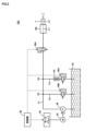
- FIG. 4 illustrates an example of a coolant mechanism.
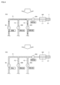
- FIG. 11 is a diagram showing a control flow of the coolant mechanism in steps S1 and S2.
- FIG. 11 is a diagram showing a control flow of the coolant mechanism in steps S3 and S4.
- FIG. 2 illustrates an example of a hardware configuration of a control unit.
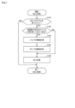
- 10 is a flowchart showing a flow of pre-processing for tool replacement.
- 1 is a flowchart showing a flow of processing of a workpiece.
- Fig. 1 is a diagram showing the external appearance of machine tool 100.
- machine tool as used in this specification is a concept that includes various devices that have the function of machining a workpiece.
- the machine tool may be a horizontal machining center or a vertical machining center.
- the machine tool may be a lathe, or other cutting machine, grinding machine, multi-tasking machine, five-axis machine, etc.
- the machine tool is not limited to those that perform only removal processing, but may also perform additional processing in addition to removal processing.
- the machine tool 100 has a tool storage section 40A and a machine body 40B. Each of the tool storage section 40A and the machine body 40B is partitioned by a cover.
- the tool storage section 40A is provided with a magazine 150 and an ATC (Automatic Tool Changer) 160.
- the processing machine body 40B is provided with a spindle head 170.
- the spindle head 170 includes a spindle tube 175 and a spindle 180.
- the spindle 180 is supported by the spindle tube 175 so that it can rotate around its axial direction.
- a tool selected from the magazine 150 is attached to the spindle 180. More specifically, the machine tool 100 drives the magazine 150 to move a tool (hereinafter also referred to as the "next tool to be used”) corresponding to the machining process to a first tool change position. The machine tool 100 also drives the spindle head 170 to move the tool (hereinafter also referred to as the "used tool") attached to the spindle 180 to a second tool change position. The ATC 160 then exchanges the next tool to be used waiting at the first tool change position with the used tool waiting at the second tool change position. The tool exchange is performed via a door D provided in the partition between the processing machine main body 40B and the tool storage section 40A. The door D is a sliding door that is opened and closed by a drive source such as a motor. The machine tool 100 then processes the workpiece using the next tool to be used attached to the spindle 180.
- a drive source such as a motor
- the machine tool 100 is also provided with an operation panel 400.
- the operation panel 400 includes a display 405 for displaying various information related to machining, and operation keys 406 for receiving various operations for the machine tool 100.
- Fig. 2 is a diagram showing an example of the coolant mechanism.
- the machine tool 100 has coolant flow paths F1 to F3, a control unit 50, a coolant tank 52, a motor driver 54, a pump 56, a pressure-retaining valve 58A (first valve), a drawback valve 58B (second valve), an orifice valve 58C (third valve), and a main shaft 180.
- the names of the valves are given to facilitate identification of the valves based on the main functions of the flow paths F1 to F3, and should not be interpreted as necessarily having the function of each valve alone.
- the drawback valve 58B may realize the drawback function by itself, or may realize the drawback function in cooperation with other fluid devices such as an ejector.
- the orifice valve 58C can also be controlled to any opening degree, and may realize the function of an orifice by itself, or may realize the function in cooperation with a separately provided fluid device such as an orifice.
- flow path F1 One end of flow path F1 is connected to coolant tank 52.
- the other end of flow path F1 is connected to a communication passage L1 formed in spindle 180.
- the side of the coolant flow path closer to coolant tank 52 is also referred to as the "upstream side”
- the side of the coolant flow path closer to spindle 180 is also referred to as the "downstream side.”
- Flow path F2 branches off from flow path F1 at branch point P2. That is, one end of flow path F2 is connected to flow path F1.
- the other end of flow path F2 may be connected to any desired destination.
- the other end of flow path F2 is connected to coolant tank 52.
- the other end of flow path F2 may be connected to a storage unit other than coolant tank 52.
- Flow path F3 branches off from flow path F1 at branch point P3.
- one end of flow path F3 is connected to flow path F1.
- the other end of flow path F3 may be connected to any desired destination.
- the other end of flow path F3 is connected to coolant tank 52.
- the other end of flow path F3 may be connected to a storage unit other than coolant tank 52.
- a communication passage L1 is formed inside the main shaft 180.
- the communication passage L1 passes through the inside of the main shaft 180 along the axial direction of the main shaft 180.
- a tool T having a through passage L2 formed therein is attached to the spindle 180.
- the through passage L2 extends from the connection surface between the tool T and the spindle 180 to the tip of the tool T, and passes through the tool T along the axial direction of the spindle 180.
- the opening of the through passage L2 formed in the tool T is not limited to being formed on the base end surface or tip end surface of the tool T, and may be an opening on the side portion of the tool T, for example.
- the through passage L2 inside the tool T is connected to the communication passage L1 inside the spindle 180.
- the control unit 50 controls various devices within the machine tool 100.
- the device configuration of the control unit 50 is arbitrary.
- the control unit 50 may be configured as a single control unit, or may be configured as multiple control units.
- the control unit 50 includes at least one of a PLC (Programmable Logic Controller) and a CNC (Computer Numerical Control).
- the objects controlled by the control unit 50 include, for example, the pump 56, the pressure maintaining valve 58A, the drawback valve 58B, and the orifice valve 58C.
- the pump 56 is provided in the flow path F1 and pumps the coolant from the coolant tank 52 to the flow path F1.
- the force with which the coolant is pumped is controlled by the control unit 50.
- a motor 55 is connected to the pump 56.
- the motor 55 is driven by a motor driver 54.
- the motor driver 54 is composed of a control circuit, an inverter, and the like.
- the motor driver 54 receives a control signal from the control unit 50, and outputs an alternating current having a frequency according to the control signal to the motor 55. This changes the rotation speed of the motor 55, and controls the flow rate of the coolant pumped to the flow path F1.
- the pressure maintaining valve 58A is provided in the flow path F1 or the connecting passage L1. In the example of FIG. 2, the pressure maintaining valve 58A is provided in the flow path F1. The pressure maintaining valve 58A is also provided downstream of the pump 56.
- the pressure maintaining valve 58A is configured to be switchable between at least two states, an open state and a closed state, in response to a control command from the control unit 50.
- the opening degree of the pressure maintaining valve 58A may be adjustable or may be constant.
- the pressure maintaining valve 58A is provided in the flow path F1, but the installation position of the pressure maintaining valve 58A is not limited to on the flow path F1.
- the pressure maintaining valve 58A may be provided on the communication passage L1 inside the main shaft 180.
- the drawback valve 58B is provided, for example, on the flow path F2 that branches off from the flow path F1.
- the drawback valve 58B is a valve that can at least switch whether or not to return the coolant located on the pressure-maintaining valve 58A side of the branch point P2 to the flow path F2 that branches off from the flow path F1 between the pump 56 and the pressure-maintaining valve 58A.
- the drawback valve 58B is configured to be switchable between at least two states, an open state and a closed state, in response to a control command from the control unit 50.
- the opening degree of the drawback valve 58B may be adjustable or may be constant.
- the drawback valve 58B is located upstream of the pressure-retaining valve 58A.
- the length of the coolant flow path between the pressure-retaining valve 58A and the spindle 180 is shorter than the length of the coolant flow path between the drawback valve 58B and the spindle 180.
- Orifice valve 58C is provided on flow path F3, which branches off from flow path F1 at branch point P3, and controls the flow of coolant in flow path F3.
- flow path F3 also has an orifice provided as fluid resistance FR upstream of orifice valve 58C.
- the orifice valve 58C is configured to be able to switch whether or not to apply fluid resistance FR to the coolant flowing through flow path F3 by opening and closing it.
- Branch point P3 between flow paths F2 and F3 is provided downstream of branch point P2 between flow paths F1 and F2.
- the orifice valve 58C is configured to be switchable between at least two states, an open state and a closed state, in response to a control command from the control unit 50.
- the opening degree of the orifice valve 58C may be adjustable or may be constant.
- the orifice valve 58C is located upstream of the pressure maintaining valve 58A.
- the length of the coolant flow path between the pressure maintaining valve 58A and the spindle 180 is shorter than the length of the coolant flow path between the orifice valve 58C and the spindle 180.
- Fig. 3 is a diagram showing a control flow of the coolant mechanism in steps S1 and S2.
- Fig. 4 is a diagram showing a control flow of the coolant mechanism in steps S3 and S4.
- the pressure-holding valve 58A, the drawback valve 58B, and the orifice valve 58C in this embodiment are normally closed type valves that are closed when no voltage is applied. That is, each valve is always closed, but is opened when a command signal from the control unit 50 is input. Needless to say, even if each valve is a normally open type valve that is open when no voltage is applied, it is possible to make it function similarly to this embodiment by appropriately setting the control signal.
- Step S1 shows the state of the coolant mechanism while the workpiece is being machined.
- the control unit 50 opens only the pressure retention valve 58A. In other words, the drawback valve 58B and the orifice valve 58C are not changed from their closed states.
- the control unit 50 then controls the pump 56 to pump the coolant into the flow path F1.
- the coolant pumped through the flow path F1 is discharged from the tip of the tool T via the communication passage L1 and the through passage L2.
- control unit 50 receives a command to stop the coolant from being discharged from the tool T or a command to replace the tool T. As a result, the control unit 50 stops driving the pump 56 and executes the drawback process shown in step S2.
- step S2 the control unit 50 switches the drawback valve 58B from a closed state to an open state.
- the control unit 50 also maintains the pressure maintaining valve 58A in an open state.
- the orifice valve 58C is maintained in a closed state.
- the control unit 50 then returns at least the amount of coolant that is present from the pressure maintaining valve 58A to the opening on the tip side of the tool T to the flow path F2.
- the coolant remaining in the communication passage L1, the through passage L2, and the flow path F1 is discharged from the flow path F2. This makes it possible to prevent the coolant from dripping from the tool T or the spindle 180.
- a suction mechanism such as an ejector (not shown) is provided at branch point P2 or flow path F2.
- coolant at a predetermined flow rate or pressure supplied from pump 56 flows into the ejector, thereby exerting a suction effect on the downstream side of branch point P2.
- the coolant downstream of branch point P2 flows back from flow path F1 into flow path F2.
- step S3 the control unit 50 changes the pressure maintaining valve 58A from an open state to a closed state.
- the control unit 50 then drives the pump 56 to fill the flow path F1 between the pump 56 and the pressure maintaining valve 58A with coolant. This shortens the time it takes for coolant to be discharged from the tip of the tool T when a new tool T having a through passage L2 is attached to the spindle 180.
- step S3 the control unit 50 closes the drawback valve 58B as shown in the example of FIG. 4. This prevents the coolant from flowing out of the flow path F2.
- the orifice valve 58C may be in an open state or in a closed state.
- the control unit 50 sets the orifice valve 58C in an open state. If the orifice valve 58C is in an open state, the pressure of the coolant in the flow path can be prevented from rising too much above a predetermined value even if the pump 56 is not completely stopped but is kept running at the minimum drive frequency. Therefore, even if the coolant is repeatedly discharged and stopped, it is possible to prevent an increase in power consumption caused by repeatedly stopping and starting the pump 56 as in the conventional method.
- the pressure maintaining valve 58A is provided on the spindle 180 side on the flow path F1.
- the spindle 180 side refers to the vicinity of the spindle 180 on the flow path F1.
- the spindle 180 side refers to the flow path between the center of the flow path F1 and the spindle 180.
- the spindle 180 side refers to the flow path between the branch point P2 or branch point P3 and the spindle 180.
- step S4 the control unit 50 changes the orifice valve 58C from an open state to a closed state.
- the pressure retention valve 58A is maintained in a closed state
- the drawback valve 58B is maintained in a closed state. After that, the control unit 50 stops the pump 56.
- step S4 the control unit 50 needs to continue driving the pump 56 at the minimum driving frequency.
- the control unit 50 drives the pump 56 at the minimum driving frequency while maintaining the orifice valve 58C in an open state.
- the minimum driving frequency is lower than the driving frequency of the pump 56 in step S3.
- FIG. 5 is a diagram showing an example of the hardware configuration of the control unit 50.
- the control unit 50 includes a control circuit 101, a ROM (Read Only Memory) 102, a RAM (Random Access Memory) 103, a communication interface 104, and an auxiliary storage device 120. These components are connected to an internal bus 109.
- the control circuit 101 is, for example, composed of at least one integrated circuit.
- the integrated circuit may be, for example, composed of at least one CPU, at least one GPU (Graphics Processing Unit), at least one ASIC (Application Specific Integrated Circuit), at least one FPGA (Field Programmable Gate Array), or a combination thereof.
- the control circuit 101 controls the operation of the control unit 50 by executing various programs such as the control program 122.
- the control program 122 is a program for implementing the various processes shown in FIG. 3 and FIG. 4 described above. Based on receiving an execution command for the control program 122, the control circuit 101 reads the control program 122 from the auxiliary storage device 120 or ROM 102 to the RAM 103.
- the RAM 103 functions as a working memory, and temporarily stores various data required for the execution of the control program 122.
- the communication interface 104 is an interface for performing periodic communication with external devices using a field network.
- the external devices include, for example, the above-mentioned pump 56, the above-mentioned pressure maintaining valve 58A, the above-mentioned drawback valve 58B, and the above-mentioned orifice valve 58C.
- As the field network for example, EtherCAT (registered trademark), EtherNet/IP (registered trademark), CC-Link (registered trademark), or CompoNet (registered trademark) is used.
- the auxiliary storage device 120 is, for example, a storage medium such as a hard disk or a flash memory.
- the auxiliary storage device 120 stores the control program 122 and the like. Note that the storage location of the control program 122 is not limited to the auxiliary storage device 120, and may be stored in a memory area of the control circuit 101 (for example, a cache memory), the ROM 102, the RAM 103, an external device (for example, a server), etc.
- control program 122 may be provided not as a standalone program, but as part of an arbitrary program. In this case, the various processes according to this embodiment are realized in cooperation with the arbitrary program. Even if the program does not include some of these modules, it does not deviate from the spirit of the control program 122 according to this embodiment. Furthermore, some or all of the functions provided by the control program 122 may be realized by dedicated hardware. Furthermore, the control unit 50 may be configured in the form of a so-called cloud service in which at least one server executes part of the processes of the control program 122.
- Fig. 6 is a flow chart showing the flow of the pre-processing for tool change.
- the process shown in FIG. 6 is realized by the control unit 50 of the machine tool 100 executing the above-mentioned control program 122. In other aspects, some or all of the process may be performed by a CNC, circuit elements, or other hardware.
- step S110 the control unit 50 determines whether or not a tool change command to remove the above-mentioned tool T (see FIG. 2) from the spindle 180 has been received. If the control unit 50 determines that the tool change command has been received (YES in step S110), it switches control to step S112. If not (NO in step S110), the control unit 50 ends the process shown in FIG. 6.
- step S112 the control unit 50 controls the pump 56 to stop the discharge of coolant from the tool T.
- the pump 56 may continue to be driven at, for example, the minimum driving frequency, or may be stopped completely.
- step S114 the control unit 50 starts the coolant drawback process. More specifically, the control unit 50 opens the pressure retention valve 58A, opens the drawback valve 58B, and closes the orifice valve 58C. This causes the coolant remaining in the communication passage L1, the through passage L2, and the flow path F1 to be discharged from the flow path F2.
- the control unit 50 switches control from step S114 to step S116 after a predetermined time has elapsed since starting the drawback process in step S114.
- the predetermined time may be set in advance or may be set arbitrarily by the user. As an example, the predetermined time is set to be equal to or longer than the time required to return the amount of coolant from the pressure retention valve 58A to the opening on the tip side of the tool T to the flow path F2. This can reliably prevent the coolant from dripping from the tool T or the spindle 180.
- step S116 the control unit 50 starts the coolant filling process. More specifically, the control unit 50 closes the pressure maintaining valve 58A, closes the drawback valve 58B, and opens the orifice valve 58C. The control unit 50 then drives the pump 56 to pump the coolant to the above-mentioned flow path F1. This causes the coolant to fill the flow path from the coolant tank 52 to the pressure maintaining valve 58A.
- the control unit 50 switches control from step S116 to step S118 after a predetermined time has elapsed since the start of the filling process in step S116.
- the predetermined time may be set in advance or may be set arbitrarily by the user. As an example, it is set to be equal to or longer than the time required to fill the flow path from the coolant tank 52 to the pressure maintaining valve 58A with coolant.
- step S118 the control unit 50 controls the ATC 160 to execute the tool replacement process. More specifically, the control unit 50 removes the tool T attached to the spindle 180, and attaches the next tool to be used, which is specified in the machining program, to the spindle 180.
- Fig. 7 is a flow chart showing the flow of the processing of a workpiece.
- the process shown in FIG. 7 is realized by the control unit 50 of the machine tool 100 executing the above-mentioned control program 122. In other aspects, some or all of the process may be performed by a CNC, circuit elements, or other hardware.
- step S150 the control unit 50 determines whether or not it has received input of an NC program, which is, for example, a machining program for machining a workpiece. If the control unit 50 determines that an NC program has been received (YES in step S150), it switches control to step S160. If not (NO in step S150), the control unit 50 ends the process shown in FIG. 7.
- an NC program which is, for example, a machining program for machining a workpiece.
- step S160 the control unit 50 judges whether the machining was performed using the above-mentioned tool T (see FIG. 2) in which the through passage L2 is formed.
- the control unit 50 judges that the machining was performed using the tool T in which the through passage L2 is formed.
- the control unit 50 judges that the machining was performed using the above-mentioned tool T (YES in step S160)
- the control unit 50 switches control to step S166.
- step S162 the control unit 50 opens the pressure maintaining valve 58A, closes the drawback valve 58B, and closes the orifice valve 58C.
- step S164 the control unit 50 drives the pump 56 so that coolant is ejected from the tool T.
- step S166 the control unit 50 drives the spindle 180 according to the machining program to perform machining of the workpiece.
- the coolant mechanism of the above embodiment is provided with the flow path F3 and the orifice valve 58C, but for example, when the pump 56 does not need to be driven all the time, the flow path F3 and the orifice valve 58C may be omitted. Or, even if the pump 56 needs to be driven all the time at the lowest driving frequency at which the discharge capacity is the smallest, when the pressure-holding valve 58A is closed, the drawback valve 58B on the flow path F2 may be opened, and a part of the coolant discharged from the pump 56 may be returned to the coolant tank 52 through the flow path F2.
- the drawback valve 58B is not an opening/closing valve, but a control valve whose opening can be adjusted.
- the drawback valve 58B may be opened to an opening for drawback, and during the filling process, the opening of the drawback valve 58B may be controlled to a filling opening smaller than the opening for drawback.
- a predetermined flow path resistance can be generated in the flow path F2 during the filling process.
Landscapes
- Engineering & Computer Science (AREA)
- Mechanical Engineering (AREA)
- General Engineering & Computer Science (AREA)
- Auxiliary Devices For Machine Tools (AREA)
- Control Of Positive-Displacement Pumps (AREA)
Abstract
Description
まず、図1を参照して、実施の形態に従う工作機械100について説明する。図1は、工作機械100の外観を示す図である。
次に、図2を参照して、工作機械100の内部に設けられているクーラント機構について説明する。図2は、クーラント機構の一例を示す図である。
次に、図3および図4を参照して、上述のポンプ56、上述の保圧バルブ58A、上述のドローバックバルブ58B、および上述のオリフィスバルブ58Cなどのクーラント機構の制御態様について説明する。図3は、ステップS1,S2におけるクーラント機構の制御フローを示す図である。図4は、ステップS3,S4におけるクーラント機構の制御フローを示す図である。なお、本実施形態における保圧バルブ58A、ドローバックバルブ58B、オリフィスバルブ58Cは電圧が印加されていない状態において閉鎖された状態となるノーマルクローズタイプのバルブである。つまり、各バルブは常時閉鎖された状態であるが、制御部50の指令信号が入力されている場合には開放される。言うまでもないことであるが、各バルブについて電圧が印加されていない状態において開放された状態となるノーマルオープンタイプのバルブであったとしても、制御信号を適切に設定することで本実施形態と同様の機能を発揮させることは可能である。
図5を参照して、上述の図2に示される制御部50のハードウェア構成について説明する。図5は、制御部50のハードウェア構成の一例を示す図である。
次に、図6を参照して、上述のATC160による工具交換の前処理に係るフローチャートについて説明する。図6は、工具交換の前処理の流れを示すフローチャートである。
次に、図7を参照して、ワークの加工処理に係るフローチャートについて説明する。図7は、ワークの加工処理の流れを示すフローチャートである。
前述した実施形態のクーラント機構は流路F3およびオリフィスバルブ58Cが設けられていたが、たとえばポンプ56を常時駆動し続けなくてもよい場合には、流路F3およびオリフィスバルブ58Cを省略した構成であってもよい。あるいはポンプ56を最も吐出容量の小さくなる最低駆動周波数で常時駆動し続けなくてはならない場合であっても、保圧バルブ58Aが閉じられた状態では、流路F2上のドローバックバルブ58Bを開き、ポンプ56から吐出されるクーラントの一部について流路F2を介してクーラントタンク52へ戻すようにしてもよい。なお、このような変形例においては、ドローバックバルブ58Bは開閉バルブではなく、その開度を調節できる制御バルブであるのが好ましい。ドローバック処理時には、ドローバックバルブ58Bをドローバック用の開度に開放し、充填処理時にはドローバックバルブ58Bの開度をドローバック用の開度よりも小さい充填開度に制御してもよい。このようにすれば、充填処理時には流路F2に所定の流路抵抗を発生させることができる。つまり、ポンプ56から吐出されたすべてのクーラントが流路F2を介してクーラントタンク52に戻されるのを防ぎ、ポンプ56から吐出された一部のクーラントだけを流路F2からクーラントタンク52に戻すことができる。したがって、流路F1において流路F2の分岐点よりも下流側であり、保圧バルブ58Aがある部分までの部分に対してポンプ56を駆動し続けながら充填処理を行うことが可能となる。
Claims (8)
- 貫通路が形成されており、当該貫通路の先端側の開口からクーラントを外部に吐出可能に構成された工具を用いてワークを加工することが可能な工作機械であって、
前記工具を装着可能に構成されており、当該工具が装着された際に前記貫通路に接続される連通路を有している主軸と、
前記連通路に接続されている第1流路にクーラントを圧送するためのポンプと、
前記第1流路または前記連通路に設けられた第1バルブと、
前記第1流路において前記ポンプと前記第1バルブとの間から分岐する第2流路に対して、前記第2流路の分岐点よりも前記第1バルブ側にあるクーラントを戻すかどうかを少なくとも切り替え可能な第2バルブと、
前記工作機械を制御するための制御部とを備え、
前記制御部は、
前記工具から外部へのクーラントの吐出を停止させる場合に、前記第2バルブを開け、少なくとも前記第1バルブから前記工具の先端側の前記開口までにある分量のクーラントが前記第2流路へと戻されるドローバック処理と、
前記ドローバック処理の実行後において前記第1バルブを閉じ、前記ポンプと前記第1バルブとの間における前記第1流路をクーラントで満たす充填処理とを実行する、工作機械。 - 前記第1バルブは、前記第1流路上に設けられており、
前記第1バルブと前記主軸との間における流路の長さは、前記第2バルブと前記主軸との間における流路の長さよりも短い、請求項1に記載の工作機械。 - 前記工作機械は、さらに、前記第1流路において前記ポンプと前記第1バルブの間から分岐している第3流路に設けられた第3バルブを備え、
前記充填処理は、前記第3バルブを開く処理を含む、請求項1または2に記載の工作機械。 - 前記第1バルブは、前記第1流路上に設けられており、
前記第1バルブと前記主軸との間における流路の長さは、前記第3バルブと前記主軸との間における流路の長さよりも短い、請求項3に記載の工作機械。 - 前記第1流路と前記第3流路との分岐点は、前記第1流路と前記第2流路との分岐点よりも前記主軸側に設けられている、請求項3または4に記載の工作機械。
- 前記制御部は、前記ドローバック処理の実行を開始してから所定時間が経過した後に、前記充填処理の実行を開始する、請求項1~5のいずれか1項に記載の工作機械。
- 貫通路が形成されており、当該貫通路の先端側の開口からクーラントを外部に吐出可能に構成された工具を用いてワークを加工することが可能な工作機械の制御方法であって、
前記工作機械は、
前記工具を装着可能に構成されており、当該工具が装着された際に前記貫通路に接続される連通路を有している主軸と、
前記連通路に接続されている第1流路にクーラントを圧送するためのポンプと、
前記第1流路または前記連通路に設けられた第1バルブと、
前記第1流路において前記ポンプと前記第1バルブとの間から分岐する第2流路に対して、前記第2流路の分岐点よりも前記第1バルブ側にあるクーラントを戻すかどうかを少なくとも切り替え可能な第2バルブとを備え、
前記制御方法は、
前記工具から外部へのクーラントの吐出を停止させる場合に、前記第2バルブを開け、少なくとも前記第1バルブから前記工具の先端側の前記開口までにある分量のクーラントを前記第2流路へ戻すステップと、
前記戻すステップの実行後において前記第1バルブを閉じ、前記ポンプと前記第1バルブとの間における前記第1流路をクーラントで満たすステップとを備える、制御方法。 - 貫通路が形成されており、当該貫通路の先端側の開口からクーラントを外部に吐出可能に構成された工具を用いてワークを加工することが可能な工作機械の制御プログラムであって、
前記工作機械は、
前記工具を装着可能に構成されており、当該工具が装着された際に前記貫通路に接続される連通路を有している主軸と、
前記連通路に接続されている第1流路にクーラントを圧送するためのポンプと、
前記第1流路または前記連通路に設けられた第1バルブと、
前記第1流路において前記ポンプと前記第1バルブとの間から分岐する第2流路に対して、前記第2流路の分岐点よりも前記第1バルブ側にあるクーラントを戻すかどうかを少なくとも切り替え可能な第2バルブとを備え、
前記制御プログラムは、前記工作機械に、
前記工具から外部へのクーラントの吐出を停止させる場合に、前記第2バルブを開け、少なくとも前記第1バルブから前記工具の先端側の前記開口までにある分量のクーラントを前記第2流路へ戻すステップと、
前記戻すステップの実行後において前記第1バルブを閉じ、前記ポンプと前記第1バルブとの間における前記第1流路をクーラントで満たすステップとを実行させる、制御プログラム。
Priority Applications (5)
| Application Number | Priority Date | Filing Date | Title |
|---|---|---|---|
| JP2023532391A JP7344420B1 (ja) | 2023-03-02 | 2023-03-02 | 工作機械、工作機械の制御方法、および工作機械の制御プログラム |
| EP23925305.7A EP4667153A4 (en) | 2023-03-02 | 2023-03-02 | MACHINE TOOL, MACHINE TOOL CONTROL METHOD AND MACHINE TOOL CONTROL PROGRAM |
| PCT/JP2023/007720 WO2024180750A1 (ja) | 2023-03-02 | 2023-03-02 | 工作機械、工作機械の制御方法、および工作機械の制御プログラム |
| CN202380094975.2A CN120693228A (zh) | 2023-03-02 | 2023-03-02 | 机床、机床的控制方法和机床的控制程序 |
| JP2023140260A JP7504272B1 (ja) | 2023-03-02 | 2023-08-30 | 工作機械 |
Applications Claiming Priority (1)
| Application Number | Priority Date | Filing Date | Title |
|---|---|---|---|
| PCT/JP2023/007720 WO2024180750A1 (ja) | 2023-03-02 | 2023-03-02 | 工作機械、工作機械の制御方法、および工作機械の制御プログラム |
Publications (1)
| Publication Number | Publication Date |
|---|---|
| WO2024180750A1 true WO2024180750A1 (ja) | 2024-09-06 |
Family
ID=87934810
Family Applications (1)
| Application Number | Title | Priority Date | Filing Date |
|---|---|---|---|
| PCT/JP2023/007720 Ceased WO2024180750A1 (ja) | 2023-03-02 | 2023-03-02 | 工作機械、工作機械の制御方法、および工作機械の制御プログラム |
Country Status (4)
| Country | Link |
|---|---|
| EP (1) | EP4667153A4 (ja) |
| JP (2) | JP7344420B1 (ja) |
| CN (1) | CN120693228A (ja) |
| WO (1) | WO2024180750A1 (ja) |
Families Citing this family (1)
| Publication number | Priority date | Publication date | Assignee | Title |
|---|---|---|---|---|
| JP7644868B1 (ja) * | 2024-10-31 | 2025-03-12 | Dmg森精機株式会社 | 工作機械、制御方法、および制御プログラム |
Citations (4)
| Publication number | Priority date | Publication date | Assignee | Title |
|---|---|---|---|---|
| JPH08141879A (ja) * | 1994-11-11 | 1996-06-04 | Koryo Denki Kk | 給油装置 |
| JP2003068680A (ja) * | 2001-08-28 | 2003-03-07 | Disco Abrasive Syst Ltd | 加工液供給機構 |
| JP2013013968A (ja) | 2011-07-04 | 2013-01-24 | Makino Milling Mach Co Ltd | 工作機械のクーラント供給装置およびクーラント供給方法 |
| JP2016092368A (ja) * | 2014-11-11 | 2016-05-23 | 東京エレクトロン株式会社 | 基板液処理装置の洗浄方法、記憶媒体及び基板液処理装置 |
Family Cites Families (4)
| Publication number | Priority date | Publication date | Assignee | Title |
|---|---|---|---|---|
| JPH0764138B2 (ja) * | 1989-09-30 | 1995-07-12 | 凸版印刷株式会社 | カード及び画像形成方法 |
| JP2965468B2 (ja) * | 1994-10-19 | 1999-10-18 | 株式会社牧野フライス製作所 | 加工液供給装置 |
| JP5984706B2 (ja) * | 2013-02-07 | 2016-09-06 | 三菱重工工作機械株式会社 | クーラント吸引装置及び工作機械 |
| JP7489299B2 (ja) * | 2020-11-26 | 2024-05-23 | オークマ株式会社 | 工作機械の切削液供給回収装置 |
-
2023
- 2023-03-02 CN CN202380094975.2A patent/CN120693228A/zh active Pending
- 2023-03-02 JP JP2023532391A patent/JP7344420B1/ja active Active
- 2023-03-02 EP EP23925305.7A patent/EP4667153A4/en active Pending
- 2023-03-02 WO PCT/JP2023/007720 patent/WO2024180750A1/ja not_active Ceased
- 2023-08-30 JP JP2023140260A patent/JP7504272B1/ja active Active
Patent Citations (4)
| Publication number | Priority date | Publication date | Assignee | Title |
|---|---|---|---|---|
| JPH08141879A (ja) * | 1994-11-11 | 1996-06-04 | Koryo Denki Kk | 給油装置 |
| JP2003068680A (ja) * | 2001-08-28 | 2003-03-07 | Disco Abrasive Syst Ltd | 加工液供給機構 |
| JP2013013968A (ja) | 2011-07-04 | 2013-01-24 | Makino Milling Mach Co Ltd | 工作機械のクーラント供給装置およびクーラント供給方法 |
| JP2016092368A (ja) * | 2014-11-11 | 2016-05-23 | 東京エレクトロン株式会社 | 基板液処理装置の洗浄方法、記憶媒体及び基板液処理装置 |
Non-Patent Citations (1)
| Title |
|---|
| See also references of EP4667153A1 |
Also Published As
| Publication number | Publication date |
|---|---|
| JP7344420B1 (ja) | 2023-09-13 |
| JP2024124303A (ja) | 2024-09-12 |
| EP4667153A4 (en) | 2026-04-08 |
| JPWO2024180750A1 (ja) | 2024-09-06 |
| CN120693228A (zh) | 2025-09-23 |
| JP7504272B1 (ja) | 2024-06-21 |
| EP4667153A1 (en) | 2025-12-24 |
Similar Documents
| Publication | Publication Date | Title |
|---|---|---|
| US20040113573A1 (en) | Reversible automatic fan control system | |
| JP7504272B1 (ja) | 工作機械 | |
| EP1793127B1 (en) | Fluid pressure unit and control method for the same | |
| EP3690258A1 (en) | Hydraulic device | |
| JP2014512285A (ja) | 流体供給システム及び製品 | |
| US6341953B1 (en) | Hydraulic drive system of an injection molding machine | |
| JP7644868B1 (ja) | 工作機械、制御方法、および制御プログラム | |
| JP7660254B1 (ja) | 工作機械、制御方法、および制御プログラム | |
| CN106239253B (zh) | 机床的控制装置 | |
| JPWO2024180750A5 (ja) | ||
| CN115734838B (zh) | 机床 | |
| JP4473097B2 (ja) | 成形機の油圧装置 | |
| JP2006206205A (ja) | リフティングマグネットを備えた作業機械の油圧制御回路 | |
| JP3722099B2 (ja) | 加工装置 | |
| JPH1078003A (ja) | 液圧装置 | |
| JPH1134135A (ja) | 射出成形機における射出駆動装置の圧抜き方法及び制御方法 | |
| KR102488617B1 (ko) | 공기 유압 펌프 | |
| KR100996000B1 (ko) | 절삭유 토출압 자동전환장치 | |
| US20250207518A1 (en) | Oil pressure control system and control method thereof | |
| JP7448114B2 (ja) | 車両の制御装置 | |
| JPH09277339A (ja) | 油圧シリンダの速度制御方法 | |
| JPH09166101A (ja) | 液圧閉回路における回路圧保持装置 | |
| KR100653876B1 (ko) | 적응적 운행제어 시스템의 유압 제동제어 장치 | |
| KR101931555B1 (ko) | 공작기계의 제어 시스템 | |
| KR101960690B1 (ko) | 해양플랜트용 자동 유량보상 유압시스템 |
Legal Events
| Date | Code | Title | Description |
|---|---|---|---|
| WWE | Wipo information: entry into national phase |
Ref document number: 2023532391 Country of ref document: JP |
|
| 121 | Ep: the epo has been informed by wipo that ep was designated in this application |
Ref document number: 23925305 Country of ref document: EP Kind code of ref document: A1 |
|
| WWE | Wipo information: entry into national phase |
Ref document number: 202380094975.2 Country of ref document: CN |
|
| WWE | Wipo information: entry into national phase |
Ref document number: 2023925305 Country of ref document: EP |
|
| WWP | Wipo information: published in national office |
Ref document number: 202380094975.2 Country of ref document: CN |
|
| NENP | Non-entry into the national phase |
Ref country code: DE |
|
| ENP | Entry into the national phase |
Ref document number: 2023925305 Country of ref document: EP Effective date: 20250919 |
|
| WWP | Wipo information: published in national office |
Ref document number: 2023925305 Country of ref document: EP |