WO2024185199A1 - マニホールド - Google Patents
マニホールド Download PDFInfo
- Publication number
- WO2024185199A1 WO2024185199A1 PCT/JP2023/039631 JP2023039631W WO2024185199A1 WO 2024185199 A1 WO2024185199 A1 WO 2024185199A1 JP 2023039631 W JP2023039631 W JP 2023039631W WO 2024185199 A1 WO2024185199 A1 WO 2024185199A1
- Authority
- WO
- WIPO (PCT)
- Prior art keywords
- housing
- flow path
- temperature
- refrigerant
- plate member
- Prior art date
- Legal status (The legal status is an assumption and is not a legal conclusion. Google has not performed a legal analysis and makes no representation as to the accuracy of the status listed.)
- Ceased
Links
Images



Classifications
-
- F—MECHANICAL ENGINEERING; LIGHTING; HEATING; WEAPONS; BLASTING
- F25—REFRIGERATION OR COOLING; COMBINED HEATING AND REFRIGERATION SYSTEMS; HEAT PUMP SYSTEMS; MANUFACTURE OR STORAGE OF ICE; LIQUEFACTION SOLIDIFICATION OF GASES
- F25B—REFRIGERATION MACHINES, PLANTS OR SYSTEMS; COMBINED HEATING AND REFRIGERATION SYSTEMS; HEAT PUMP SYSTEMS
- F25B41/00—Fluid-circulation arrangements
- F25B41/40—Fluid line arrangements
- F25B41/42—Arrangements for diverging or converging flows, e.g. branch lines or junctions
-
- B—PERFORMING OPERATIONS; TRANSPORTING
- B60—VEHICLES IN GENERAL
- B60H—ARRANGEMENTS OF HEATING, COOLING, VENTILATING OR OTHER AIR-TREATING DEVICES SPECIALLY ADAPTED FOR PASSENGER OR GOODS SPACES OF VEHICLES
- B60H1/00—Heating, cooling or ventilating devices
- B60H1/00507—Details, e.g. mounting arrangements, desaeration devices
- B60H1/00557—Details of ducts or cables
- B60H1/00571—Details of ducts or cables of liquid ducts, e.g. for coolant liquids or refrigerants
-
- B—PERFORMING OPERATIONS; TRANSPORTING
- B60—VEHICLES IN GENERAL
- B60H—ARRANGEMENTS OF HEATING, COOLING, VENTILATING OR OTHER AIR-TREATING DEVICES SPECIALLY ADAPTED FOR PASSENGER OR GOODS SPACES OF VEHICLES
- B60H1/00—Heating, cooling or ventilating devices
- B60H1/32—Cooling devices
- B60H1/3204—Cooling devices using compression
- B60H1/3229—Cooling devices using compression characterised by constructional features, e.g. housings, mountings, conversion systems
-
- F—MECHANICAL ENGINEERING; LIGHTING; HEATING; WEAPONS; BLASTING
- F25—REFRIGERATION OR COOLING; COMBINED HEATING AND REFRIGERATION SYSTEMS; HEAT PUMP SYSTEMS; MANUFACTURE OR STORAGE OF ICE; LIQUEFACTION SOLIDIFICATION OF GASES
- F25B—REFRIGERATION MACHINES, PLANTS OR SYSTEMS; COMBINED HEATING AND REFRIGERATION SYSTEMS; HEAT PUMP SYSTEMS
- F25B2339/00—Details of evaporators; Details of condensers
- F25B2339/04—Details of condensers
- F25B2339/047—Water-cooled condensers
-
- F—MECHANICAL ENGINEERING; LIGHTING; HEATING; WEAPONS; BLASTING
- F25—REFRIGERATION OR COOLING; COMBINED HEATING AND REFRIGERATION SYSTEMS; HEAT PUMP SYSTEMS; MANUFACTURE OR STORAGE OF ICE; LIQUEFACTION SOLIDIFICATION OF GASES
- F25B—REFRIGERATION MACHINES, PLANTS OR SYSTEMS; COMBINED HEATING AND REFRIGERATION SYSTEMS; HEAT PUMP SYSTEMS
- F25B5/00—Compression machines, plants or systems, with several evaporator circuits, e.g. for varying refrigerating capacity
- F25B5/02—Compression machines, plants or systems, with several evaporator circuits, e.g. for varying refrigerating capacity arranged in parallel
Definitions
- This disclosure relates to a manifold.
- Patent Document 1 discloses a thermal management system that includes a compressor that compresses low-temperature refrigerant vapor in a subsystem into high-temperature refrigerant vapor.
- the present disclosure has been made in consideration of the above problems, and its purpose is to provide a manifold that suppresses heat exchange between cooling fluids of different temperatures.
- the manifold according to the present disclosure is characterized in that it comprises a flow path housing including a first housing in which a first flow path is formed through which a cooling fluid at a first temperature flows, and a second housing in which a second flow path is formed through which the cooling fluid at a second temperature lower than the first temperature flows, and a plate member to which the flow path housing is joined, and the first housing and the second housing are joined to the plate member while being spaced apart.
- the first and second housings of the flow path housing are spaced apart and joined to the plate member.
- the first housing has a first flow path through which a cooling fluid of a first temperature flows
- the second housing has a second flow path through which a cooling fluid of a second temperature lower than the first temperature flows.
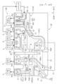
- FIG. 1 is a diagram showing a refrigerant circuit according to an embodiment.
- 5A and 5B are schematic diagrams illustrating a flow path housing and a plate member according to the embodiment.
- 5A and 5B are diagrams illustrating a configuration of a flow path housing according to the embodiment.
- FIG. 4 is an enlarged view of a first housing shown in FIG. 3 .
- FIG. 4 is an enlarged view of a second housing shown in FIG. 3 .
- a refrigerant circuit C mounted on a vehicle such as an electric vehicle, a hybrid vehicle, or a fuel cell vehicle will be described with reference to Fig. 1.
- the refrigerant circuit C is configured by a refrigerant flow path L through which a refrigerant F1 for cooling and heating that adjusts the temperature inside the vehicle flows.
- the refrigerant F1 is, for example, a hydrofluorocarbon (HFC), a hydrofluoroolefin (HFO), or the like.
- the refrigerant flow path L is configured by a manifold 100 (see Figs. 2 and 3) mounted on the vehicle.
- the refrigerant circuit C includes a compressor 1 (an example of a compressor), a cabin condenser 2 (a heating condenser), a water-cooled condenser 3 (an example of a condenser), an evaporator 4 (an example of an evaporator), a battery cooler 5 (an example of an evaporator), an accumulator 6, and a valve V.
- the compressor 1, the cabin condenser 2, the water-cooled condenser 3, the evaporator 4, the battery cooler 5, the accumulator 6, and the valve V are connected via a refrigerant flow path L.
- the valve V includes an on-off valve V1 provided between the water-cooled condenser 3 and the accumulator 6.
- the valve V also includes a first expansion valve VE1 provided between the cabin condenser 2 and the water-cooled condenser 3, and a second expansion valve VE2 provided between the water-cooled condenser 3 and the evaporator 4.
- the on-off valve V1 controls (passes or blocks) the flow of refrigerant F1 between the water-cooled condenser 3 and the accumulator 6.
- the refrigerant F1 flows in the following order: compressor 1, cabin condenser 2, first expansion valve VE1, water-cooled condenser 3, on-off valve V1, accumulator 6, and compressor 1.
- the refrigerant circuit C consisting of the compressor 1, cabin condenser 2, water-cooled condenser 3, on-off valve V1, and accumulator 6 will be referred to as the "main circuit Cm.”
- the first expansion valve VE1 and the second expansion valve VE2 expand the refrigerant F1 to adjust the pressure of the refrigerant F1.
- the refrigerant F1 flows through the second expansion valve VE2 and the evaporator 4 in that order, and then flows into the main circuit Cm between the on-off valve V1 and the accumulator 6.
- the refrigerant circuit C that branches off from the main circuit Cm and in which the second expansion valve VE2 and the evaporator 4 are provided is referred to as the "first branch circuit Cb1."
- the on-off valve V1 is opened and the second expansion valve VE2 is closed.
- the on-off valve V1 is closed and the second expansion valve VE2 is opened.
- the battery cooler 5 includes an expansion valve, and the expansion valve of the battery cooler 5 is opened when adjusting the temperature of the battery.
- the expansion valve of the battery cooler 5 is opened, the refrigerant F1 flows through the battery cooler 5 and then into the main circuit Cm between the on-off valve V1 and the accumulator 6.
- the refrigerant circuit C that branches off from the main circuit Cm and in which the battery cooler 5 is provided is referred to as the "second branch circuit Cb2.”
- Compressor 1 compresses refrigerant F1 to make it into a high-pressure gas.
- the temperature of refrigerant F1 compressed by compressor 1 is referred to as the first heat medium temperature (an example of the first temperature).
- the first heat medium temperature is, for example, 80 degrees to 90 degrees.
- the refrigerant F1 compressed by the compressor 1 is sent to the cabin condenser 2, where it exchanges heat with the air in the vehicle cabin during heating operation (heat is removed and the temperature is reduced), and is then sent to the water-cooled condenser 3 via the first expansion valve VE1.
- a first heat medium F2 circulating in a circuit separate from the refrigerant circuit C (for example, a cooling circuit for cooling electronic circuits mounted on the vehicle) flows.
- the first heat medium F2 is a refrigerant such as cooling water such as long-life coolant (LLC), insulating oil such as paraffin, hydrofluorocarbon (HFC), hydrofluoroolefin (HFO), etc.
- the refrigerant F1 sent to the water-cooled condenser 3 exchanges heat with the first heat medium F2 flowing through the water-cooled condenser 3 (heat is removed and the temperature is reduced).
- the temperature of the refrigerant F1 after being cooled by the water-cooled condenser 3 is referred to as the second heat medium temperature (an example of the second temperature).
- the second heat transfer medium temperature is, for example, 60°C to 85°C, and the refrigerant F1 is a high-pressure liquid after being cooled by the water-cooled condenser 3.
- the refrigerant F1 sent to the second expansion valve VE2 is expanded into a mixture of liquid and gas (mist) and sent to the evaporator 4.
- the temperature of the refrigerant F1 after it has expanded in the second expansion valve VE2 is referred to as the third heat medium temperature (an example of the second temperature).
- the third heat medium temperature is, for example, 15°C to 25°C.
- the refrigerant F1 is vaporized through heat exchange with air introduced from the outside (heat is removed and the temperature is raised).
- the refrigerant F1 sent to the battery cooler 5 is expanded by the expansion valve of the battery cooler 5.
- the battery cooler 5 is also circulated with a second heat medium F3 circulating in a circuit (for example, a cooling circuit for cooling a battery mounted on a vehicle) separate from the refrigerant circuit C.
- the second heat medium F3 is a refrigerant such as cooling water such as long-life coolant (LLC), insulating oil such as paraffin, hydrofluorocarbon (HFC), hydrofluoroolefin (HFO), etc.
- the refrigerant F1 sent to the battery cooler 5 is vaporized by heat exchange (heating up by removing heat) with the second heat medium F3 circulating in the battery cooler 5.
- the fourth heat medium temperature an example of the third temperature.
- the fourth heat medium temperature is, for example, 15 degrees to 25 degrees.
- the refrigerant F1 after heat exchange in the evaporator 4 is sent to the accumulator 6, where the liquid contained in the refrigerant F1 is separated.
- the refrigerant F1 from which the liquid has been separated returns to the compressor 1.
- the refrigerant F1 after heat exchange in the battery cooler 5 is also sent to the accumulator 6, where the liquid contained in the refrigerant F1 is separated.
- the refrigerant F1 from which the liquid has been separated returns to the compressor 1.
- the temperature of the refrigerant F1 flowing through the refrigerant flow path L in the refrigerant circuit C changes.
- the temperature of the refrigerant F1 is highest when it travels from the compressor 1 to the water-cooled condenser 3 (first heat medium temperature), next highest when it travels from the water-cooled condenser 3 to the second expansion valve VE2 and/or the battery cooler 5 (second heat medium temperature), and lowest when it travels from the second expansion valve VE2 to the evaporator 4 (third heat medium temperature) and when it travels from the evaporator 4 and/or the battery cooler 5 to the accumulator 6 (fourth heat medium temperature).
- the first heat medium temperature is referred to as "high temperature”
- the second heat medium temperature is referred to as "medium temperature”
- the third heat medium temperature and the fourth heat medium temperature are referred to as "low temperature”.
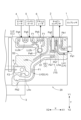
- Fig. 2 and Fig. 3 are diagrams showing the configuration of the manifold 100.
- Fig. 3 is a diagram showing the flow path housing 10 as viewed from the opposite side to the plate member 20, and shows a cross section with a wall provided on the opposite side of the flow path housing 10 to the plate member 20 removed.
- the manifold 100 includes a flow path housing 10 and a plate member 20.
- the plate member 20 is rectangular in plan view (see Figure 3), and each of the flow path housing 10 and the plate member 20 is made of a metal (including an alloy) that contains aluminum.
- the flow path housing 10 is separated into two parts.
- one of the two flow path housings 10 will be referred to as the "first housing 11" and the other will be referred to as the "second housing 12.”
- the first housing 11 and the second housing 12 are spaced apart and joined to the plate member 20.
- Each of the first housing 11 and the second housing 12 is joined to the plate member 20 by, for example, bolts or the like.
- the refrigerant flow path L described with reference to FIG. 1 is formed between the flow path housing 10 and the plate member 20 (see FIG. 3).
- a part of the heat medium flow path R is also formed in the flow path housing 10 near the water-cooled condenser 3.
- the first heat medium F2 (see FIG. 1), which is to exchange heat with the refrigerant F1 in the water-cooled condenser 3, flows through the heat medium flow path R.
- the refrigerant flow path L includes a high-temperature flow path LH (an example of a first flow path) through which refrigerant F1 at a first heat medium temperature (high temperature) flows from the compressor 1 to the water-cooled condenser 3, a medium-temperature flow path LM (an example of a second flow path) through which refrigerant F1 at a second heat medium temperature (medium temperature) flows from the water-cooled condenser 3 to the second expansion valve VE2 and/or the battery cooler 5, and a low-temperature flow path LL through which refrigerant F1 at a third heat medium temperature (low temperature) flows from the second expansion valve VE2 to the evaporator 4, and refrigerant F1 at a fourth heat medium temperature (low temperature) flows from the evaporator 4 and/or the battery cooler 5 to the accumulator 6.
- LH an example of a first flow path
- LM an example of a second flow path
- the low-temperature flow path LL includes a first low-temperature flow path LL1 (an example of a second flow path) through which the refrigerant F1 flows from the second expansion valve VE2 to the evaporator 4, and a second low-temperature flow path LL2 (an example of a third flow path) through which the refrigerant F1 flows from the evaporator 4 and/or the battery cooler 5 to the accumulator 6.
- the compressor 1, cabin condenser 2, water-cooled condenser 3, evaporator 4, battery cooler 5, accumulator 6 and valve V (on-off valve V1, first expansion valve VE1 and second expansion valve VE2) are provided outside the flow path housing 10. Therefore, the flow path housing 10 is formed with inlet and outlet ports through which refrigerant F1 flows between the compressor 1, cabin condenser 2, water-cooled condenser 3, evaporator 4, battery cooler 5, accumulator 6 and each of the valves V.
- the inlets through which the refrigerant F1 flows from the compressor 1, cabin condenser 2, water-cooled condenser 3, evaporator 4, and battery cooler 5 into the flow path housing 10 are referred to as the "first inlet Pa1,” “second inlet Pa2,” “third inlet Pa3,” “fourth inlet Pa4,” and “fifth inlet Pa5,” respectively, and the outlets through which the refrigerant F1 flows out of the flow path housing 10 toward the cabin condenser 2, water-cooled condenser 3, evaporator 4, battery cooler 5, and accumulator 6 are referred to as the "first outlet Pb1," “second outlet Pb2,” “third outlet Pb3,” “fourth outlet Pb4,” and “fifth outlet Pb5,” respectively.
- the inlets through which the refrigerant F1 flows into the flow path housing 10 from the on-off valve V1, the first expansion valve VE1, and the second expansion valve VE2 are respectively referred to as the “sixth inlet Pa6,” the “seventh inlet Pa7,” and the “eighth inlet Pa8,” and the outlets through which the refrigerant F1 flows out of the flow path housing 10 toward the on-off valve V1, the first expansion valve VE1, and the second expansion valve VE2 are respectively referred to as the “sixth outlet Pb6,” the “seventh outlet Pb7,” and the “eighth outlet Pb8.”
- the refrigerant flow path L through which the refrigerant F1 flows from the accumulator 6 to the compressor 1 is provided outside the flow path housing 10. Therefore, the inlet through which the refrigerant F1 flows from the accumulator 6 into the flow path housing 10 and the outlet through which the refrigerant F1 flows from the flow path housing 10 to the compressor 1 are not formed in the flow path housing 10.
- the direction toward the first inlet Pa1 when viewed from the center O of the plate member 20 is referred to as the "X1 direction”, the opposite direction is referred to as the “X2 direction”, and the direction along the X1 and X2 directions is referred to as the "X direction”.
- the direction toward the fourth outlet Pb4 when viewed from the center O of the plate member 20 is referred to as the "Y1 direction”
- the opposite direction is referred to as the "Y2 direction”
- the direction along the Y1 and Y2 directions is referred to as the "Y direction”.
- the X direction and the Y direction are perpendicular to each other.
- the center O of the plate member 20 is the intersection of the diagonals of the plate member 20.
- Fig. 4 is an enlarged view of the first housing 11 shown in Fig. 3.
- the high temperature flow path LH includes a first high temperature flow path LH1 through which the refrigerant F1 flows from the compressor 1 to the cabin condenser 2, and a second high temperature flow path LH2 through which the refrigerant F1 flows from the cabin condenser 2 to the water-cooled condenser 3 via the first expansion valve VE1.
- the first high-temperature flow passage LH1 extends in an L-shape from the first inlet Pa1 provided at the end of the first housing 11 in the X1 direction to the first outlet Pb1 provided at the end of the first housing 11 in the Y1 direction.
- the second high-temperature flow passage LH2 has a base end at the second inlet Pa2 provided at the end of the first housing 11 in the Y1 direction and extends to a second outlet Pb2 provided at the end in the X2 direction.
- the second high-temperature flow passage LH2 includes a first high-temperature extension portion LHa having a base end at the second inlet Pa2 and extending along the Y direction to the seventh outlet Pb7, a second high-temperature extension portion LHb having a base end at the seventh inlet Pa7 and curving to bulge in the Y1 direction and the X2 direction, and a third high-temperature extension portion LHc having a base end at the end of the second high-temperature extension portion LHb and extending along the X direction to the second outlet Pb2.
- the first high-temperature extension portion LHa extends to a position in the Y2 direction as viewed from the second low-temperature flow passage LL2. That is, the second high-temperature extension portion LHb and the third high-temperature extension portion LHc are located in the Y2 direction when viewed from the second low-temperature flow path LL2.
- the second low-temperature flow passage LL2 has a fourth inlet Pa4 at the end of the first housing 11 in the X2 direction and the Y1 direction, and extends in a T-shape to the fifth outlet Pb5 and the sixth inlet Pa6.
- the fifth inlet Pa5 and the fifth outlet Pb5 are provided at the end of the first housing 11 in the Y1 direction.
- the fourth inlet Pa4, the fifth inlet Pa5, and the fifth outlet Pb5 are provided in this order along the X1 direction.
- the second low-temperature flow passage LL2 includes a first low-temperature extension portion LL2a extending along the X direction and a second low-temperature extension portion LL2b extending along the Y direction perpendicular to the first low-temperature extension portion LL2a.
- the second low-temperature extension portion LL2b has the sixth inlet Pa6 at one end and the fifth inlet Pa5 at the other end.
- the first housing 11 includes a first slit S1 formed between the high temperature flow passage LH and the second low temperature flow passage LL2.
- the first slit S1 extends from between the high temperature flow passage LH (first high temperature extension LHa) and the second low temperature flow passage LL2 (second low temperature extension LL2b) at the end of the first housing 11 in the Y1 direction along the second high temperature flow passage LH2 (first high temperature extension LHa and second high temperature extension LHb) to a position beyond the sixth inlet Pa6.
- the first slit S1 in the first housing 11 air having a lower thermal conductivity than the material of the flow passage housing 10 is interposed between the high temperature flow passage LH and the second low temperature flow passage LL2, and heat exchange between the refrigerant F1 flowing through the high temperature flow passage LH and the refrigerant F1 flowing through the second low temperature flow passage LL2 is suppressed.
- the first housing 11 further includes a second slit S2 formed between the second low-temperature flow path LL2 and the heat medium flow path R through which the first heat medium F2 flows.
- the second slit S2 extends from between the heat medium flow path R and the first low-temperature extension portion LL2a at the end of the first housing 11 in the X2 direction along the first low-temperature extension portion LL2a in the X1 direction to just before the sixth inlet Pa6.
- air is interposed between the second low-temperature flow path LL2 and the heat medium flow path R, suppressing heat exchange between the refrigerant F1 flowing through the second low-temperature flow path LL2 and the first heat medium F2 flowing through the heat medium flow path R.
- the heat medium flow path R is located in the Y1 direction as viewed from the third high-temperature extension portion LHc.
- Fig. 5 is an enlarged view of the second housing 12 shown in Fig. 3.
- the second housing 12 is provided with a medium temperature flow passage LM and a first low temperature flow passage LL1.
- the medium temperature flow passage LM has a third inlet Pa3 provided at the end of the second housing 12 in the X1 direction and the Y2 direction as a base end, and extends through a sixth outlet Pb6 to an eighth outlet Pb8 and a fourth outlet Pb4 provided at the end of the second housing 12 in the Y1 direction.
- the medium temperature flow passage LM includes a first medium temperature extension portion LMa having a base end at the third inlet Pa3 and extending along the Y direction to the fourth outlet Pb4, and a second medium temperature extension portion LMb branching from the first medium temperature extension portion LMa at the sixth outlet Pb6 and extending along the X direction to the eighth outlet Pb8.
- the first low-temperature flow passage LL1 has the eighth inlet Pa8 as its base end and extends in the Y direction to the third outlet Pb3 provided at the Y1 end of the second housing 12.
- the third outlet Pb3 is located in the X2 direction as viewed from the fourth outlet Pb4.
- the second housing 12 includes a third slit S3 formed between the medium temperature flow path LM and the first low temperature flow path LL1.
- the third slit S3 extends along the first low temperature flow path LL1 from between the medium temperature flow path LM (first medium temperature extension portion LMa) and the first low temperature flow path LL1 to just before the eighth outlet Pb8 on the end of the second housing 12 in the Y1 direction.
- air is interposed between the first low temperature flow path LL1 and the medium temperature flow path LM, and heat exchange between the refrigerant F1 flowing through the first low temperature flow path LL1 and the refrigerant F1 flowing through the medium temperature flow path LM is suppressed.
- the second housing 12 further includes a fourth slit S4 formed between the first low-temperature flow path LL1 and the medium-temperature flow path LM and the heat medium flow path R.
- the fourth slit S4 extends in the X1 direction from between the first low-temperature flow path LL1 (second expansion valve VE2) and the heat medium flow path R at the end of the X2 direction of the second housing 12, and bends in the Y2 direction at a position beyond the ninth outlet Pb9.
- air is interposed between the first low-temperature flow path LL1 and the medium-temperature flow path LM and the heat medium flow path R, suppressing heat exchange between the refrigerant F1 flowing through the first low-temperature flow path LL1 and the medium-temperature flow path LM and the first heat medium F2 flowing through the heat medium flow path R.
- the heat medium flow path R is located in the Y2 direction as viewed from the first low-temperature flow path LL1 and in the X2 direction as viewed from the medium-temperature flow path LM.
- the plate member 20 has a flat opposing surface 21 (main surface) that faces the flow path housing 10, a groove portion 22 that is recessed in a direction away from the flow path housing 10 with respect to the opposing surface 21, and a heat insulating material 23 that is arranged in the groove portion 22.
- the groove portion 22 is formed, for example, by cutting the plate member 20. In this embodiment, the groove portion 22 does not penetrate the plate member 20, and each of the first slit S1 to the fourth slit S4 penetrates the plate member 20. However, the groove portion 22 may penetrate the plate member 20.
- the opposing surface 21 of the plate member 20 includes a portion where the first housing 11 and the second housing 12 are separated in the X direction, i.e., a non-opposing region 21R that does not face either the first housing 11 or the second housing 12.
- the groove portion 22 is provided in the non-opposing region 21R.
- a heat insulating material 23 is disposed in the groove portion 22. This suppresses heat conduction through the plate member 20.
- the heat insulating material 23 is made of a resin or the like that has a lower thermal conductivity than the plate member 20.
- the first housing 11, in which the high-temperature flow path LH through which the high-temperature refrigerant F1 flows, and the second housing 12, in which the medium-temperature flow path LM through which the medium-temperature refrigerant F1, which is lower in temperature than the high-temperature refrigerant F1, flows, are separated (separated) and joined to the plate member 20.
- the first housing 11 and the second housing 12 are not integral with each other and are separated from each other, air having low thermal conductivity is interposed between the first housing 11 and the second housing 12. Therefore, heat exchange between refrigerants F1 of different temperatures can be suppressed.
- the refrigerant F1 flows from the compressor 1 to the water-cooled condenser 3 through the high-temperature flow path LH, and the refrigerant F1 flows from the water-cooled condenser 3 to the evaporator 4 and/or battery cooler 5 through the medium-temperature flow path LM, and the refrigerant F1 has a lower temperature than that of the high-temperature flow path LH. Therefore, it is possible to suppress heat exchange between the refrigerant F1 flowing from the compressor 1 to the water-cooled condenser 3 and the refrigerant F1 flowing from the water-cooled condenser 3 to the evaporator 4 and/or battery cooler 5.
- the first slit S1 is formed in the first housing 11 between the high-temperature flow path LH and the second low-temperature flow path LL2 through which the refrigerant F1 flows at a temperature (fourth heat medium temperature) lower than the temperature of the refrigerant F1 flowing through the high-temperature flow path LH (first heat medium temperature), so that heat exchange between different refrigerants F1 can be suppressed. Even if the first housing 11 cannot be separated due to circumstances such as ensuring strength to hold the water-cooled condenser 3, for example, by providing the first slit S1, heat exchange between refrigerants F1 of different temperatures can be suppressed. Furthermore, there is no need to further divide the first housing 11, and an increase in the number of parts can be avoided.
- a groove portion 22 is formed in the plate member 20 between the first housing 11 and the second housing 12, and a heat insulating material 23 is disposed in the groove portion 22. Therefore, it is possible to suppress heat conduction between the first housing 11 and the second housing 12 via the plate member 20.
- the number, position, and shape of the slits (first slit S1 and second slit S2) provided in the first housing 11 are not limited to those described in the embodiment, and can be changed as appropriate according to the position and shape of the refrigerant flow path L so as to suppress heat exchange between refrigerants F1 of different temperatures flowing through the refrigerant flow path L.
- the plate member 20 has the groove portion 22 and the insulating material 23 arranged in the groove portion 22.
- the plate member 20 may omit the groove portion 22 and the insulating material 23. In this case, it is preferable to select a material with low thermal conductivity as the material for the plate member 20.
- the refrigerant circuit C (second branch circuit Cb2) is described as having a battery cooler 5 as an example, but the refrigerant circuit C may have a chiller instead of the battery cooler 5.
- the refrigerant circuit C has a chiller instead of the battery cooler 5
- the refrigerant circuit C further includes an expansion valve as a valve V between the water-cooled condenser 3 and the chiller.
- refrigerant F1 has been described as an example of a cooling fluid, but the present disclosure may also use fluids other than refrigerant F1, such as cooling water such as long-life coolant (LLC), insulating oil such as paraffin, etc.
- cooling water such as long-life coolant (LLC)
- LLC long-life coolant
- insulating oil such as paraffin
- the plate member 20 is rectangular, but the shape of the plate member 20 is not limited to a rectangular shape and can be changed as appropriate.
- the material of the flow path housing 10 and the plate member 20 is not limited to a metal containing aluminum, and may be a metal other than aluminum, a resin, etc.
- the manifold 100 is characterized in that it comprises a flow path housing 10 including a first housing 11 in which a high-temperature flow path LH (first flow path) is formed, through which a refrigerant F1 (cooling fluid) of a first temperature flows, and a second housing 12 in which a medium-temperature flow path LM (second flow path) is formed, through which a refrigerant F1 (cooling fluid) of a second temperature lower than the first temperature flows, and a plate member 20 to which the flow path housing 10 is joined, and the first housing 11 and the second housing 12 are spaced apart and joined to the plate member 20.
- LH high-temperature flow path
- LM medium-temperature flow path
- the first housing 11 and the second housing 12 of the flow path housing 10 are spaced apart and joined to the plate member 20.
- the first housing 11 is formed with a high-temperature flow path LH (first flow path) through which a refrigerant F1 (cooling fluid) of a first temperature flows
- the second housing 12 is formed with a medium-temperature flow path LM (second flow path) through which a refrigerant F1 (cooling fluid) of a second temperature lower than the first temperature flows.
- the first housing 11 and the second housing 12 are not integral and are spaced apart from each other, so that air with low thermal conductivity is interposed between the first housing 11 and the second housing 12. Therefore, heat exchange between refrigerants F1 (cooling fluids) of different temperatures can be suppressed.
- the high-temperature flow path LH (first flow path) may carry refrigerant F1 (cooling fluid) from the compressor 1 (compressor) to the water-cooled condenser 3 (condenser), and the medium-temperature flow path LM (second flow path) may carry refrigerant F1 (cooling fluid) from the water-cooled condenser 3 (condenser) to the evaporator 4 and/or battery cooler 5 (evaporator).
- This configuration makes it possible to suppress heat exchange between the relatively high-temperature refrigerant F1 (cooling fluid) flowing from the compressor 1 (compressor) to the water-cooled condenser 3 (condenser) and the relatively low-temperature refrigerant F1 (cooling fluid) flowing from the water-cooled condenser 3 (condenser) to the evaporator 4 and/or battery cooler 5 (evaporator).
- the first housing 11 is formed with a second low-temperature flow path LL2 (third flow path) through which a refrigerant F1 (cooling fluid) of a third temperature lower than the first temperature flows, and a slit may be formed between the high-temperature flow path LH (first flow path) and the second low-temperature flow path LL2 (third flow path).
- a slit is formed in the first housing 11 between the high-temperature flow path LH (first flow path) through which refrigerant F1 (cooling fluid) of a first temperature flows, and the second low-temperature flow path LL2 (third flow path) through which refrigerant F1 (cooling fluid) of a third temperature lower than the first temperature flows, so that heat exchange between refrigerants F1 (cooling fluids) of different temperatures can be suppressed.
- the plate member 20 may have a groove portion 22 formed between the first housing 11 and the second housing 12.
- a groove portion 22 is formed in the plate member 20 between the first housing 11 and the second housing 12. Therefore, heat conduction between the first housing 11 and the second housing 12 can be suppressed via the plate member 20.
- the plate member 20 may further have a heat insulating material 23 disposed in the groove portion 22.
- the plate member 20 further includes a heat insulating material 23 disposed in a groove portion 22 formed between the first housing 11 and the second housing 12. Therefore, it is possible to suppress heat conduction between the first housing 11 and the second housing 12 via the plate member 20.
- This disclosure can be used in manifolds.
Landscapes
- Engineering & Computer Science (AREA)
- Physics & Mathematics (AREA)
- Thermal Sciences (AREA)
- Mechanical Engineering (AREA)
- General Engineering & Computer Science (AREA)
- Air-Conditioning For Vehicles (AREA)
- Secondary Cells (AREA)
Abstract
Description
まず、図1を参照して、電気自動車、ハイブリッド車、燃料電池車等の車両に搭載される冷媒回路Cについて説明する。冷媒回路Cは、車両の室内の温度を調整する冷暖房用の冷媒F1が流通する冷媒流路Lによって構成される。冷媒F1は、例えば、ハイドロフルオロカーボン(HFC)、ハイドロフルオロオレフィン(HFO)等である。なお、冷媒流路Lは、車両に搭載されるマニホールド100(図2及び図3参照)によって構成される。
続いて、図2及び図3を参照して、図1を参照して説明した冷媒流路Lが形成されるマニホールド100の構成について説明する。図2及び図3は、マニホールド100の構成を示す図である。なお、図3は、プレート部材20とは反対側から見た流路ハウジング10を示す図であり、流路ハウジング10のプレート部材20とは反対側に設けられる壁を取り除いた断面を示す。
流路ハウジング10は、2つに分離されている。以下、2つの流路ハウジング10の一方を「第1ハウジング11」といい、他方を「第2ハウジング12」という。第1ハウジング11と第2ハウジング12とは離間してプレート部材20に接合される。第1ハウジング11及び第2ハウジング12の各々は、例えば、ボルト等によってプレート部材20に接合される。
図3に示すように、冷媒流路Lは、コンプレッサ1から水冷コンデンサ3へ向かう第1熱媒温度(高温)の冷媒F1が流れる高温流路LH(第1流路の一例)と、水冷コンデンサ3から第2膨張弁VE2及び/又はバッテリクーラ5へ向かう第2熱媒温度(中温)の冷媒F1が流れる中温流路LM(第2流路の一例)と、第2膨張弁VE2からエバポレータ4へ向かう第3熱媒温度(低温)の冷媒F1、及び、エバポレータ4及び/又はバッテリクーラ5からアキュムレータ6へ向かう第4熱媒温度(低温)の冷媒F1が流れる低温流路LLと、を含む。なお、低温流路LLは、第2膨張弁VE2からエバポレータ4へ向かう冷媒F1が流れる第1低温流路LL1(第2流路の一例)と、エバポレータ4及び/又はバッテリクーラ5からアキュムレータ6へ向かう冷媒F1が流れる第2低温流路LL2(第3流路の一例)と、含む。
次に、図4を参照して、第1ハウジング11の構成について説明する。図4は、図3に示す第1ハウジング11の拡大図である。
図4に示すように、第1ハウジング11には、高温流路LHと第2低温流路LL2とが設けられる(形成されている)。高温流路LHは、コンプレッサ1からキャビンコンデンサ2へ向かう冷媒F1が流れる第1高温流路LH1と、キャビンコンデンサ2から第1膨張弁VE1を経て水冷コンデンサ3へ向かう冷媒F1が流れる第2高温流路LH2とを含む。
第1ハウジング11は、高温流路LHと第2低温流路LL2との間に形成される第1スリットS1を含む。第1スリットS1は、第1ハウジング11のY1方向における端のうち、高温流路LH(第1高温延在部LHa)と第2低温流路LL2(第2低温延在部LL2b)との間から、第2高温流路LH2(第1高温延在部LHa及び第2高温延在部LHb)に沿って第6流入口Pa6を超える位置まで延在する。第1ハウジング11に第1スリットS1が形成されることにより、高温流路LHと第2低温流路LL2との間に、流路ハウジング10の材料よりも熱伝導率が低い空気が介在し、高温流路LHを流れる冷媒F1と第2低温流路LL2を流れる冷媒F1との間での熱交換が抑制される。
次に、図5を参照して、第2ハウジング12の構成について説明する。図5は、図3に示す第2ハウジング12の拡大図である。
図5に示すように、第2ハウジング12には、中温流路LMと第1低温流路LL1とが設けられる。中温流路LMは、第2ハウジング12のX1方向及びY2方向における端部に設けられた第3流入口Pa3を基端とし、第6流出口Pb6を経て、第8流出口Pb8及び第2ハウジング12のY1方向における端部に設けられた第4流出口Pb4まで延在する。中温流路LMは、第3流入口Pa3を基端とし、第4流出口Pb4までY方向に沿って延在する第1中温延在部LMaと、第6流出口Pb6で第1中温延在部LMaから分岐し第8流出口Pb8までX方向に沿って延在する第2中温延在部LMbと、を含む。
第2ハウジング12は、中温流路LMと第1低温流路LL1との間に形成される第3スリットS3を含む。第3スリットS3は、第2ハウジング12のY1方向における端のうち、中温流路LM(第1中温延在部LMa)と第1低温流路LL1との間から第8流出口Pb8の手前まで、第1低温流路LL1に沿って延在する。第3スリットS3が設けられることにより、第1低温流路LL1と中温流路LMとの間に空気が介在し、第1低温流路LL1を流れる冷媒F1と中温流路LMを流れる冷媒F1との間での熱交換が抑制される。
続いて、図2に戻り、プレート部材20の構成について説明する。図2に示すように、プレート部材20は、流路ハウジング10と対向する平坦な対向面21(主面)と、対向面21よりも流路ハウジング10から離れる方向に凹む溝部22と、溝部22に配置される断熱材23とを有する。溝部22は、例えば、プレート部材20が切削されることにより形成される。本実施形態において、溝部22は、プレート部材20を貫通せず、上記の第1スリットS1~第4スリットS4の各々は、プレート部材20を貫通する。ただし、溝部22は、プレート部材20を貫通してもよい。
以上説明したように、本実施形態によれば、高温の冷媒F1が流れる高温流路LHが形成される第1ハウジング11と、高温の冷媒F1よりも低い中温の冷媒F1が流れる中温流路LMが形成される第2ハウジング12とが離間(分離)してプレート部材20に接合される。つまり、第1ハウジング11と第2ハウジング12とが一体的ではなく、第1ハウジング11と第2ハウジング12とが離間しているので、第1ハウジング11と第2ハウジング12との間には熱伝導率の低い空気が介在することとなる。したがって、異なる温度の冷媒F1間での熱交換を抑制することができる。
本開示は、上記した実施形態以外に以下のように構成してもよい(実施形態と同じ機能を有するものには、実施形態と共通の番号、符号を付している)。
Claims (5)
- 第1温度の冷却流体が流れる第1流路が形成された第1ハウジングと、前記第1温度よりも低い第2温度の前記冷却流体が流れる第2流路が形成された第2ハウジングとを含む流路ハウジングと、
前記流路ハウジングが接合されたプレート部材と、を備え、
前記第1ハウジングと前記第2ハウジングとが離間して前記プレート部材に接合されているマニホールド。 - 前記第1流路には、圧縮機から凝縮器へ向かう前記冷却流体が流れ、
前記第2流路には、前記凝縮器から蒸発器へ向かう前記冷却流体が流れる請求項1に記載のマニホールド。 - 前記第1ハウジングには、前記第1温度よりも低い第3温度の前記冷却流体が流れる第3流路が形成されており、前記第1流路と前記第3流路との間にスリットが形成されている請求項1又は2に記載のマニホールド。
- 前記プレート部材は、前記第1ハウジングと前記第2ハウジングとの間に形成された溝部を有する、請求項1又は2に記載のマニホールド。
- 前記プレート部材は、前記溝部に配置される断熱材を更に有する請求項4に記載のマニホールド。
Priority Applications (3)
| Application Number | Priority Date | Filing Date | Title |
|---|---|---|---|
| JP2025505060A JPWO2024185199A1 (ja) | 2023-03-09 | 2023-11-02 | |
| CN202380087467.1A CN120380293A (zh) | 2023-03-09 | 2023-11-02 | 歧管 |
| EP23926407.0A EP4624853A4 (en) | 2023-03-09 | 2023-11-02 | COLLECTOR |
Applications Claiming Priority (2)
| Application Number | Priority Date | Filing Date | Title |
|---|---|---|---|
| JP2023-036309 | 2023-03-09 | ||
| JP2023036309 | 2023-03-09 |
Publications (1)
| Publication Number | Publication Date |
|---|---|
| WO2024185199A1 true WO2024185199A1 (ja) | 2024-09-12 |
Family
ID=92674506
Family Applications (1)
| Application Number | Title | Priority Date | Filing Date |
|---|---|---|---|
| PCT/JP2023/039631 Ceased WO2024185199A1 (ja) | 2023-03-09 | 2023-11-02 | マニホールド |
Country Status (4)
| Country | Link |
|---|---|
| EP (1) | EP4624853A4 (ja) |
| JP (1) | JPWO2024185199A1 (ja) |
| CN (1) | CN120380293A (ja) |
| WO (1) | WO2024185199A1 (ja) |
Families Citing this family (1)
| Publication number | Priority date | Publication date | Assignee | Title |
|---|---|---|---|---|
| KR20240018078A (ko) * | 2022-08-02 | 2024-02-13 | 한온시스템 주식회사 | 매니폴드 유체 모듈 |
Citations (8)
| Publication number | Priority date | Publication date | Assignee | Title |
|---|---|---|---|---|
| JPH0737866B2 (ja) * | 1988-12-23 | 1995-04-26 | 三菱電機株式会社 | 空気調和機 |
| JP2001227777A (ja) * | 2000-02-18 | 2001-08-24 | Mitsubishi Electric Corp | 冷凍機 |
| JP2010091215A (ja) * | 2008-10-09 | 2010-04-22 | Daikin Ind Ltd | 冷媒配管ユニット |
| JP2011255879A (ja) | 2010-06-04 | 2011-12-22 | Tesla Motors Inc | デュアルモードの冷却材ループを備えた熱管理システム |
| JP2021047000A (ja) * | 2019-09-13 | 2021-03-25 | 株式会社デンソー | 接続モジュール |
| CN114670602A (zh) * | 2022-04-25 | 2022-06-28 | 苏州市振业实业有限公司 | 汽车热管理系统装置及电动汽车 |
| CN114791183A (zh) * | 2021-01-24 | 2022-07-26 | 浙江三花汽车零部件有限公司 | 流体管理装置 |
| KR20220162479A (ko) * | 2021-06-01 | 2022-12-08 | 한온시스템 주식회사 | 통합 쿨링 모듈 |
Family Cites Families (3)
| Publication number | Priority date | Publication date | Assignee | Title |
|---|---|---|---|---|
| CN115195390A (zh) * | 2021-04-12 | 2022-10-18 | 浙江三花汽车零部件有限公司 | 流体管理装置及热管理系统 |
| CN115218564B (zh) * | 2021-04-16 | 2024-06-11 | 浙江三花汽车零部件有限公司 | 一种连接装置及一种集成组件 |
| CN115610190A (zh) * | 2021-07-15 | 2023-01-17 | 浙江三花汽车零部件有限公司 | 热管理装置 |
-
2023
- 2023-11-02 CN CN202380087467.1A patent/CN120380293A/zh active Pending
- 2023-11-02 JP JP2025505060A patent/JPWO2024185199A1/ja active Pending
- 2023-11-02 WO PCT/JP2023/039631 patent/WO2024185199A1/ja not_active Ceased
- 2023-11-02 EP EP23926407.0A patent/EP4624853A4/en active Pending
Patent Citations (8)
| Publication number | Priority date | Publication date | Assignee | Title |
|---|---|---|---|---|
| JPH0737866B2 (ja) * | 1988-12-23 | 1995-04-26 | 三菱電機株式会社 | 空気調和機 |
| JP2001227777A (ja) * | 2000-02-18 | 2001-08-24 | Mitsubishi Electric Corp | 冷凍機 |
| JP2010091215A (ja) * | 2008-10-09 | 2010-04-22 | Daikin Ind Ltd | 冷媒配管ユニット |
| JP2011255879A (ja) | 2010-06-04 | 2011-12-22 | Tesla Motors Inc | デュアルモードの冷却材ループを備えた熱管理システム |
| JP2021047000A (ja) * | 2019-09-13 | 2021-03-25 | 株式会社デンソー | 接続モジュール |
| CN114791183A (zh) * | 2021-01-24 | 2022-07-26 | 浙江三花汽车零部件有限公司 | 流体管理装置 |
| KR20220162479A (ko) * | 2021-06-01 | 2022-12-08 | 한온시스템 주식회사 | 통합 쿨링 모듈 |
| CN114670602A (zh) * | 2022-04-25 | 2022-06-28 | 苏州市振业实业有限公司 | 汽车热管理系统装置及电动汽车 |
Non-Patent Citations (1)
| Title |
|---|
| See also references of EP4624853A1 |
Also Published As
| Publication number | Publication date |
|---|---|
| CN120380293A (zh) | 2025-07-25 |
| EP4624853A1 (en) | 2025-10-01 |
| JPWO2024185199A1 (ja) | 2024-09-12 |
| EP4624853A4 (en) | 2026-03-18 |
Similar Documents
| Publication | Publication Date | Title |
|---|---|---|
| US20240167769A1 (en) | Integrated cooling module | |
| US20260002715A1 (en) | Manifold | |
| JP2026507573A (ja) | エネルギー貯蔵熱管理システム及び方法 | |
| US12196459B2 (en) | Solid-state cooling module | |
| CN111033877A (zh) | 冷却装置及电池调温系统 | |
| WO2024001516A1 (zh) | 压缩机后壳组件及包括其的涡旋压缩机 | |
| CN113665334A (zh) | 一种宽温域的车载散热系统 | |
| CN115280082A (zh) | 使用固态制冷剂的冷却模块和使用固态制冷剂的冷却系统 | |
| JP7602631B2 (ja) | 熱交換器、熱交換アセンブリおよび熱管理システム | |
| EP4624853A1 (en) | Manifold | |
| CN105517823A (zh) | 车辆用空调装置及其结构单元 | |
| EP4600503A1 (en) | Waste heat recovery system, method, and engineering machinery | |
| JP2025021145A (ja) | マニホールド | |
| WO2017163563A1 (ja) | 熱交換ユニットおよび車両用空調装置 | |
| US20260124885A1 (en) | Manifold | |
| CN216960622U (zh) | 发热元件的散热装置、车载计算设备及车辆 | |
| EP4624854A1 (en) | Manifold | |
| CN117565623A (zh) | 热管理集成部件、系统和车辆 | |
| JP7433965B2 (ja) | 熱交換器 | |
| JP2014137930A (ja) | 電池システム | |
| JP2021141055A (ja) | 燃料電池車両の冷却システム | |
| CN107421015A (zh) | 空调器 | |
| KR20230041517A (ko) | 유체흐름용 플레이트구조 | |
| CN222302286U (zh) | 直冷板 | |
| CN219727805U (zh) | 混合动力车辆热管理系统及车辆 |
Legal Events
| Date | Code | Title | Description |
|---|---|---|---|
| 121 | Ep: the epo has been informed by wipo that ep was designated in this application |
Ref document number: 23926407 Country of ref document: EP Kind code of ref document: A1 |
|
| WWE | Wipo information: entry into national phase |
Ref document number: 2025505060 Country of ref document: JP |
|
| WWE | Wipo information: entry into national phase |
Ref document number: 202380087467.1 Country of ref document: CN |
|
| WWE | Wipo information: entry into national phase |
Ref document number: 2023926407 Country of ref document: EP |
|
| ENP | Entry into the national phase |
Ref document number: 2023926407 Country of ref document: EP Effective date: 20250624 |
|
| WWP | Wipo information: published in national office |
Ref document number: 202380087467.1 Country of ref document: CN |
|
| WWP | Wipo information: published in national office |
Ref document number: 2023926407 Country of ref document: EP |
|
| NENP | Non-entry into the national phase |
Ref country code: DE |