WO2024185411A1 - サワー環境での使用に適した鋼材 - Google Patents
サワー環境での使用に適した鋼材 Download PDFInfo
- Publication number
- WO2024185411A1 WO2024185411A1 PCT/JP2024/004747 JP2024004747W WO2024185411A1 WO 2024185411 A1 WO2024185411 A1 WO 2024185411A1 JP 2024004747 W JP2024004747 W JP 2024004747W WO 2024185411 A1 WO2024185411 A1 WO 2024185411A1
- Authority
- WO
- WIPO (PCT)
- Prior art keywords
- steel
- content
- steel material
- temperature
- yield strength
- Prior art date
- Legal status (The legal status is an assumption and is not a legal conclusion. Google has not performed a legal analysis and makes no representation as to the accuracy of the status listed.)
- Ceased
Links
Images




Classifications
-
- C—CHEMISTRY; METALLURGY
- C22—METALLURGY; FERROUS OR NON-FERROUS ALLOYS; TREATMENT OF ALLOYS OR NON-FERROUS METALS
- C22C—ALLOYS
- C22C38/00—Ferrous alloys, e.g. steel alloys
- C22C38/18—Ferrous alloys, e.g. steel alloys containing chromium
- C22C38/40—Ferrous alloys, e.g. steel alloys containing chromium with nickel
- C22C38/54—Ferrous alloys, e.g. steel alloys containing chromium with nickel with boron
-
- C—CHEMISTRY; METALLURGY
- C21—METALLURGY OF IRON
- C21D—MODIFYING THE PHYSICAL STRUCTURE OF FERROUS METALS; GENERAL DEVICES FOR HEAT TREATMENT OF FERROUS OR NON-FERROUS METALS OR ALLOYS; MAKING METAL MALLEABLE, e.g. BY DECARBURISATION OR TEMPERING
- C21D1/00—General methods or devices for heat treatment, e.g. annealing, hardening, quenching or tempering
- C21D1/18—Hardening; Quenching with or without subsequent tempering
-
- C—CHEMISTRY; METALLURGY
- C21—METALLURGY OF IRON
- C21D—MODIFYING THE PHYSICAL STRUCTURE OF FERROUS METALS; GENERAL DEVICES FOR HEAT TREATMENT OF FERROUS OR NON-FERROUS METALS OR ALLOYS; MAKING METAL MALLEABLE, e.g. BY DECARBURISATION OR TEMPERING
- C21D1/00—General methods or devices for heat treatment, e.g. annealing, hardening, quenching or tempering
- C21D1/26—Methods of annealing
-
- C—CHEMISTRY; METALLURGY
- C21—METALLURGY OF IRON
- C21D—MODIFYING THE PHYSICAL STRUCTURE OF FERROUS METALS; GENERAL DEVICES FOR HEAT TREATMENT OF FERROUS OR NON-FERROUS METALS OR ALLOYS; MAKING METAL MALLEABLE, e.g. BY DECARBURISATION OR TEMPERING
- C21D1/00—General methods or devices for heat treatment, e.g. annealing, hardening, quenching or tempering
- C21D1/78—Combined heat-treatments not provided for above
-
- C—CHEMISTRY; METALLURGY
- C21—METALLURGY OF IRON
- C21D—MODIFYING THE PHYSICAL STRUCTURE OF FERROUS METALS; GENERAL DEVICES FOR HEAT TREATMENT OF FERROUS OR NON-FERROUS METALS OR ALLOYS; MAKING METAL MALLEABLE, e.g. BY DECARBURISATION OR TEMPERING
- C21D6/00—Heat treatment of ferrous alloys
- C21D6/002—Heat treatment of ferrous alloys containing Cr
-
- C—CHEMISTRY; METALLURGY
- C21—METALLURGY OF IRON
- C21D—MODIFYING THE PHYSICAL STRUCTURE OF FERROUS METALS; GENERAL DEVICES FOR HEAT TREATMENT OF FERROUS OR NON-FERROUS METALS OR ALLOYS; MAKING METAL MALLEABLE, e.g. BY DECARBURISATION OR TEMPERING
- C21D8/00—Modifying the physical properties of ferrous metals or ferrous alloys by deformation combined with, or followed by, heat treatment
- C21D8/10—Modifying the physical properties of ferrous metals or ferrous alloys by deformation combined with, or followed by, heat treatment during manufacturing of tubular bodies
-
- C—CHEMISTRY; METALLURGY
- C21—METALLURGY OF IRON
- C21D—MODIFYING THE PHYSICAL STRUCTURE OF FERROUS METALS; GENERAL DEVICES FOR HEAT TREATMENT OF FERROUS OR NON-FERROUS METALS OR ALLOYS; MAKING METAL MALLEABLE, e.g. BY DECARBURISATION OR TEMPERING
- C21D9/00—Heat treatment, e.g. annealing, hardening, quenching or tempering, adapted for particular articles; Furnaces therefor
- C21D9/08—Heat treatment, e.g. annealing, hardening, quenching or tempering, adapted for particular articles; Furnaces therefor for tubular bodies or pipes
-
- C—CHEMISTRY; METALLURGY
- C22—METALLURGY; FERROUS OR NON-FERROUS ALLOYS; TREATMENT OF ALLOYS OR NON-FERROUS METALS
- C22C—ALLOYS
- C22C38/00—Ferrous alloys, e.g. steel alloys
- C22C38/002—Ferrous alloys, e.g. steel alloys containing In, Mg, or other elements not provided for in one single group C22C38/001 - C22C38/60
-
- C—CHEMISTRY; METALLURGY
- C22—METALLURGY; FERROUS OR NON-FERROUS ALLOYS; TREATMENT OF ALLOYS OR NON-FERROUS METALS
- C22C—ALLOYS
- C22C38/00—Ferrous alloys, e.g. steel alloys
- C22C38/005—Ferrous alloys, e.g. steel alloys containing rare earths, i.e. Sc, Y, Lanthanides
-
- C—CHEMISTRY; METALLURGY
- C22—METALLURGY; FERROUS OR NON-FERROUS ALLOYS; TREATMENT OF ALLOYS OR NON-FERROUS METALS
- C22C—ALLOYS
- C22C38/00—Ferrous alloys, e.g. steel alloys
- C22C38/02—Ferrous alloys, e.g. steel alloys containing silicon
-
- C—CHEMISTRY; METALLURGY
- C22—METALLURGY; FERROUS OR NON-FERROUS ALLOYS; TREATMENT OF ALLOYS OR NON-FERROUS METALS
- C22C—ALLOYS
- C22C38/00—Ferrous alloys, e.g. steel alloys
- C22C38/04—Ferrous alloys, e.g. steel alloys containing manganese
-
- C—CHEMISTRY; METALLURGY
- C22—METALLURGY; FERROUS OR NON-FERROUS ALLOYS; TREATMENT OF ALLOYS OR NON-FERROUS METALS
- C22C—ALLOYS
- C22C38/00—Ferrous alloys, e.g. steel alloys
- C22C38/18—Ferrous alloys, e.g. steel alloys containing chromium
- C22C38/20—Ferrous alloys, e.g. steel alloys containing chromium with copper
-
- C—CHEMISTRY; METALLURGY
- C22—METALLURGY; FERROUS OR NON-FERROUS ALLOYS; TREATMENT OF ALLOYS OR NON-FERROUS METALS
- C22C—ALLOYS
- C22C38/00—Ferrous alloys, e.g. steel alloys
- C22C38/18—Ferrous alloys, e.g. steel alloys containing chromium
- C22C38/22—Ferrous alloys, e.g. steel alloys containing chromium with molybdenum or tungsten
-
- C—CHEMISTRY; METALLURGY
- C22—METALLURGY; FERROUS OR NON-FERROUS ALLOYS; TREATMENT OF ALLOYS OR NON-FERROUS METALS
- C22C—ALLOYS
- C22C38/00—Ferrous alloys, e.g. steel alloys
- C22C38/18—Ferrous alloys, e.g. steel alloys containing chromium
- C22C38/24—Ferrous alloys, e.g. steel alloys containing chromium with vanadium
-
- C—CHEMISTRY; METALLURGY
- C22—METALLURGY; FERROUS OR NON-FERROUS ALLOYS; TREATMENT OF ALLOYS OR NON-FERROUS METALS
- C22C—ALLOYS
- C22C38/00—Ferrous alloys, e.g. steel alloys
- C22C38/18—Ferrous alloys, e.g. steel alloys containing chromium
- C22C38/26—Ferrous alloys, e.g. steel alloys containing chromium with niobium or tantalum
-
- C—CHEMISTRY; METALLURGY
- C22—METALLURGY; FERROUS OR NON-FERROUS ALLOYS; TREATMENT OF ALLOYS OR NON-FERROUS METALS
- C22C—ALLOYS
- C22C38/00—Ferrous alloys, e.g. steel alloys
- C22C38/18—Ferrous alloys, e.g. steel alloys containing chromium
- C22C38/28—Ferrous alloys, e.g. steel alloys containing chromium with titanium or zirconium
-
- C—CHEMISTRY; METALLURGY
- C22—METALLURGY; FERROUS OR NON-FERROUS ALLOYS; TREATMENT OF ALLOYS OR NON-FERROUS METALS
- C22C—ALLOYS
- C22C38/00—Ferrous alloys, e.g. steel alloys
- C22C38/18—Ferrous alloys, e.g. steel alloys containing chromium
- C22C38/30—Ferrous alloys, e.g. steel alloys containing chromium with cobalt
-
- C—CHEMISTRY; METALLURGY
- C22—METALLURGY; FERROUS OR NON-FERROUS ALLOYS; TREATMENT OF ALLOYS OR NON-FERROUS METALS
- C22C—ALLOYS
- C22C38/00—Ferrous alloys, e.g. steel alloys
- C22C38/18—Ferrous alloys, e.g. steel alloys containing chromium
- C22C38/32—Ferrous alloys, e.g. steel alloys containing chromium with boron
-
- C—CHEMISTRY; METALLURGY
- C22—METALLURGY; FERROUS OR NON-FERROUS ALLOYS; TREATMENT OF ALLOYS OR NON-FERROUS METALS
- C22C—ALLOYS
- C22C38/00—Ferrous alloys, e.g. steel alloys
- C22C38/18—Ferrous alloys, e.g. steel alloys containing chromium
- C22C38/34—Ferrous alloys, e.g. steel alloys containing chromium with more than 1.5% by weight of silicon
-
- C—CHEMISTRY; METALLURGY
- C22—METALLURGY; FERROUS OR NON-FERROUS ALLOYS; TREATMENT OF ALLOYS OR NON-FERROUS METALS
- C22C—ALLOYS
- C22C38/00—Ferrous alloys, e.g. steel alloys
- C22C38/18—Ferrous alloys, e.g. steel alloys containing chromium
- C22C38/40—Ferrous alloys, e.g. steel alloys containing chromium with nickel
- C22C38/44—Ferrous alloys, e.g. steel alloys containing chromium with nickel with molybdenum or tungsten
-
- C—CHEMISTRY; METALLURGY
- C22—METALLURGY; FERROUS OR NON-FERROUS ALLOYS; TREATMENT OF ALLOYS OR NON-FERROUS METALS
- C22C—ALLOYS
- C22C38/00—Ferrous alloys, e.g. steel alloys
- C22C38/18—Ferrous alloys, e.g. steel alloys containing chromium
- C22C38/40—Ferrous alloys, e.g. steel alloys containing chromium with nickel
- C22C38/46—Ferrous alloys, e.g. steel alloys containing chromium with nickel with vanadium
-
- C—CHEMISTRY; METALLURGY
- C22—METALLURGY; FERROUS OR NON-FERROUS ALLOYS; TREATMENT OF ALLOYS OR NON-FERROUS METALS
- C22C—ALLOYS
- C22C38/00—Ferrous alloys, e.g. steel alloys
- C22C38/18—Ferrous alloys, e.g. steel alloys containing chromium
- C22C38/40—Ferrous alloys, e.g. steel alloys containing chromium with nickel
- C22C38/50—Ferrous alloys, e.g. steel alloys containing chromium with nickel with titanium or zirconium
Definitions
- This disclosure relates to steel materials, and more particularly to steel materials suitable for use in sour environments.
- oil wells As oil and gas wells (hereinafter, oil and gas wells will be collectively referred to simply as "oil wells") become deeper, there is a demand for higher strength steel materials for oil wells, such as oil well steel pipes.
- 80 ksi grade yield strength 80 to less than 95 ksi, i.e., 552 to less than 655 MPa
- 95 ksi grade yield strength 95 to less than 110 ksi, i.e., 655 to less than 758 MPa
- oil well steel materials are widely used, and recently, there has been a demand for 110 ksi grade (yield strength 110 to less than 125 ksi, i.e., 758 to less than 862 MPa), 125 ksi grade (yield strength 125 to less than 140 ksi, i.e., 862 to less than 965 MPa), and 140 ksi or more (yield strength 140 ksi or more, i.e.
- a sour environment means an acidic environment that contains hydrogen sulfide.
- a sour environment may also contain carbon dioxide.
- Oil well steel pipes used in such sour environments are required to have not only high strength, but also resistance to sulfide stress cracking (hereinafter referred to as SSC resistance).
- Patent Document 1 JP 2000-297344 A
- Patent Document 2 JP 2001-271134 A
- Patent Document 3 WO 2008/123422
- the oil well steel disclosed in Patent Document 1 contains, by mass%, C: 0.15-0.3%, Cr: 0.2-1.5%, Mo: 0.1-1%, V: 0.05-0.3%, and Nb: 0.003-0.1%.
- This oil well steel has a total amount of precipitated carbides of 1.5-4 mass%, a ratio of MC type carbides to the total amount of carbides of 5-45 mass%, and a ratio of M23C6 type carbides of ( 200 /t) mass% or less when the wall thickness of the product is t (mm).
- Patent Document 1 states that this oil well steel has excellent SSC resistance.
- the low alloy steel disclosed in Patent Document 2 contains, by mass%, C: 0.2-0.35%, Si: 0.05-0.5%, Mn: 0.1-1%, P: 0.025% or less, S: 0.01% or less, Cr: 0.1-1.2%, Mo: 0.1-1%, B: 0.0001-0.005%, Al: 0.005-0.1%, N: 0.01% or less, V: 0.05-0.5%, Ni: 0.1% or less, W: 1.0% or less, O: 0.01% or less, with the remainder being Fe and impurities, and satisfies the formula (0.03 ⁇ Mo ⁇ V ⁇ 0.3) and the formula (0.5 ⁇ Mo-V+GS/10 ⁇ 1), and has a yield strength of 1060 MPa or more.
- GS means the ASTM grain size number of the prior austenite grains. This low-alloy steel has excellent SSC resistance, as described in Patent Document 2.
- This low alloy steel contains 0.1 M23C6 type precipitates having a grain size of 1 ⁇ m or more per mm2 or less. This low alloy steel is described in Patent Document 3 as having improved SSC resistance.
- Patent Documents 1 to 3 above propose steel materials with excellent SSC resistance. However, Patent Documents 1 to 3 above do not consider fracture toughness in a low-temperature sour environment.
- the objective of this disclosure is to provide a steel material that has high yield strength and excellent fracture toughness in low-temperature sour environments.
- the steel material according to the present disclosure is In mass percent, C: more than 0.20 to 0.60%, Si: 0.05-2.00%, Mn: 0.02 to 0.60%, P: 0.025% or less, S: 0.0100% or less, Al: 0.005-0.100%, Cr: 0.20-1.50%, Mo: 0.35-1.50%, V: 0.01-0.60%, Ti: 0.002 to 0.050%, B: 0.0001 to 0.0050%, N: 0.0100% or less, O: 0.0100% or less, Nb: 0 to 0.030%, Ca: 0-0.0100%, Mg: 0 to 0.0100%, Zr: 0 to 0.0100%, Rare earth elements: 0 to 0.0100%, Co: 0 to 0.50%, W: 0-0.50%, Ni: 0 to 0.20%, Cu: 0 to 0.50%, and The balance is Fe and impurities, The yield strength ⁇ YS is 758 MPa or more, In the steel material, the Mo content ⁇
- Fn1 83 ⁇ ( ⁇ Mo ⁇ 10 ⁇ 7 ⁇ ) ⁇ YS (1)
- Mo content in the vicinity of the prior austenite grain boundary is substituted for ⁇ Mo in formula (1) in mass %
- the dislocation density is substituted for ⁇ in formula (1) in m ⁇ 2
- the yield strength is substituted for ⁇ YS in formula (1) in MPa.
- the steel material disclosed herein has high yield strength and excellent fracture toughness in low-temperature sour environments.
- FIG. 3 is a schematic diagram of an observation surface of a polished test piece for determining the amount of grain boundary Mo.
- FIG. 4 is a schematic diagram of a measurement area 10 in which the grain boundaries of prior austenite grains are identified.
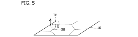
- FIG. 5 is a schematic diagram showing how a thin film sample TP is prepared from the measurement region 10 shown in FIG.
- FIG. 6 is a perspective view of the thin film sample TP shown in FIG.
- FIG. 7 is a schematic diagram for explaining the relationship between the electron beam and the prior austenite grain boundary GB in the thin film sample TP during TEM observation and elemental analysis by EDS.
- FIG. 1 is a schematic diagram of an observation surface of a polished test piece for determining the amount of grain boundary Mo.
- FIG. 4 is a schematic diagram of a measurement area 10 in which the grain boundaries of prior austenite grains are identified.
- FIG. 5 is a schematic diagram showing how a thin film sample TP is prepared from the measurement region 10 shown in FIG.
- FIG. 6 is a
- FIG. 8 is a schematic diagram showing the relationship between the irradiation direction of the electron beam EB during TEM observation and elemental analysis by EDS, the prior austenite grain boundaries GB on the surface 10 of the thin film sample TP, and the element concentration profile.
- FIG. 9 shows an example of the Mo content on a line segment SL that is centered on the prior austenite grain boundary GB and perpendicular to the prior austenite grain boundary GB.
- FIG. 10 is a schematic diagram for explaining the formula (2).
- FIG. 11 is a side view and a cross-sectional view of a DCB test piece used in an evaluation test of the fracture toughness of steel in a low-temperature sour environment (DCB test) in this embodiment.
- FIG. 12 is a perspective view of a wedge used in an evaluation test of the fracture toughness of steel in a low-temperature sour environment (DCB test) in this embodiment.
- the inventors have investigated and examined methods for obtaining steel materials with high yield strength and excellent fracture toughness in low-temperature sour environments, and have obtained the following findings.
- the inventors sought to obtain a steel material having a high yield strength of 758 MPa or more (110 ksi or more). Therefore, the inventors first investigated, from the standpoint of chemical composition, steel material having a yield strength of 110 ksi or more and excellent fracture toughness in a low-temperature sour environment.
- the inventors found that the composition is, in mass%, C: over 0.20 to 0.60%, Si: 0.05 to 2.00%, Mn: 0.02 to 0.60%, P: 0.025% or less, S: 0.0100% or less, Al: 0.005 to 0.100%, Cr: 0.20 to 1.50%, Mo: 0.35 to 1.50%, V: 0.01 to 0.60%, Ti: 0.002 to 0.050%, B: 0.0001 to 0.0050%, N: 0.0100% or less, O: 0.0100% It was thought that if the steel consisted of the following components, Nb: 0-0.030%, Ca: 0-0.0100%, Mg: 0-0.0100%, Zr: 0-0.0100%, rare earth elements: 0-0.0100%, Co: 0-0.50%, W: 0-0.50%, Ni: 0-0.20%, Cu: 0-0.50%, and the balance Fe and impurities, it would be possible to obtain a steel with a yield strength of 110 ksi or more and excellent
- the inventors investigated various methods for increasing the fracture toughness in a low-temperature sour environment for steel material having the above-mentioned chemical composition and yield strength of 110 ksi or more.
- a decrease in the toughness of the prior austenite grain boundaries in the steel material is likely to become apparent in a low-temperature sour environment, and cracks tend to propagate along the prior austenite grain boundaries in the steel material.
- prior austenite grains are also referred to as "prior gamma grains.”
- the present inventors focused on molybdenum (Mo) as an element that contributes to strengthening the prior ⁇ grain boundary. If Mo is concentrated in the prior ⁇ grain boundary, the prior ⁇ grain boundary can be strengthened, and crack propagation may be suppressed even in a low-temperature sour environment. As a result, it is possible to obtain excellent fracture toughness in a low-temperature sour environment. As a result of detailed studies by the present inventors, it has been revealed that in a steel material having the above-mentioned chemical composition and a yield strength of 110 ksi or more, if the Mo content ⁇ Mo in the vicinity of the prior ⁇ grain boundary is 5.0 mass% or more, excellent fracture toughness may be obtained.
- the Mo content ⁇ Mo in the vicinity of the prior ⁇ grain boundary is also referred to as the "grain boundary Mo content ⁇ Mo ".
- the present inventors further investigated the factors that reduce the fracture toughness of the above-mentioned steel material in detail. As a result, it was revealed that in a steel material having the above-mentioned chemical composition and yield strength, the fracture toughness in a low-temperature sour environment is affected by the dislocation density ⁇ in the steel material, the yield strength ⁇ YS of the steel material, and the grain boundary Mo content ⁇ Mo .
- Fn1 is defined as 83 ⁇ ( ⁇ Mo -10 -7 ⁇ ⁇ ) - ⁇ YS .
- Fn1 is an index of fracture toughness in a low-temperature sour environment.
- FIG. 1 was obtained using an example from among the examples described later that satisfies the above-mentioned chemical composition, has a yield strength ⁇ YS of 110 ksi class, and has a grain boundary Mo content ⁇ Mo of 5.0 mass% or more.
- the yield strength ⁇ YS , grain boundary Mo content ⁇ Mo , dislocation density ⁇ , and fracture toughness value K 1SSC value were obtained by the methods described later.
- the steel material according to this embodiment has the above-mentioned chemical composition, a grain boundary Mo content of ⁇ Mo of 5.0 mass% or more, and when the yield strength ⁇ YS is less than 758 to 862 MPa, Fn1 is set to -300 or more.
- Figure 2 was obtained using an example that satisfies the above-mentioned chemical composition, has a yield strength ⁇ YS of 125 ksi or more, and has a grain boundary Mo content ⁇ Mo of 5.0 mass% or more, among the examples described below.
- the yield strength ⁇ YS , grain boundary Mo content ⁇ Mo , dislocation density ⁇ , and fracture toughness value K1SSC value were obtained by the methods described below.
- the fracture toughness value K 1SSC value in a low-temperature sour environment is 24.1 MPa ⁇ m or more, and it can be confirmed that the steel material shows stable and excellent fracture toughness.
- Fn1 is less than -520
- the fracture toughness value K 1SSC value in a low-temperature sour environment is less than 24.1 MPa ⁇ m, and excellent fracture toughness is not shown.
- the steel material according to this embodiment has the above-mentioned chemical composition, a grain boundary Mo content of ⁇ Mo of 5.0 mass% or more, and when the yield strength ⁇ YS is 862 MPa or more, Fn1 is set to -520 or more.
- Fn1 specifies the relationship between the yield strength ⁇ YS , the grain boundary Mo amount ⁇ Mo , and the dislocation density ⁇ .
- the dislocation increases the yield strength ⁇ YS of the steel material while absorbing hydrogen.
- the dislocation density ⁇ contributes to the improvement of the yield strength ⁇ YS .
- the inventors speculate that the steel material according to this embodiment can obtain high strength and excellent fracture toughness in a low-temperature sour environment by the above mechanism. It is possible that the fracture toughness in a low-temperature sour environment can be improved by adjusting Fn1 in a steel material having the above chemical composition, yield strength ⁇ YS , and grain boundary Mo content ⁇ Mo by a mechanism other than the above mechanism. However, it is proven by the examples described later that the fracture toughness in a low-temperature sour environment can be improved by adjusting Fn1 in a steel material having the above chemical composition, yield strength ⁇ YS , and grain boundary Mo content ⁇ Mo.
- the gist of the steel material according to this embodiment which was completed based on the above findings, is as follows:
- a steel material In mass percent, C: more than 0.20 to 0.60%, Si: 0.05-2.00%, Mn: 0.02 to 0.60%, P: 0.025% or less, S: 0.0100% or less, Al: 0.005-0.100%, Cr: 0.20-1.50%, Mo: 0.35-1.50%, V: 0.01-0.60%, Ti: 0.002 to 0.050%, B: 0.0001 to 0.0050%, N: 0.0100% or less, O: 0.0100% or less, Nb: 0 to 0.030%, Ca: 0-0.0100%, Mg: 0 to 0.0100%, Zr: 0 to 0.0100%, Rare earth elements: 0 to 0.0100%, Co: 0 to 0.50%, W: 0-0.50%, Ni: 0 to 0.20%, Cu: 0 to 0.50%, and The balance is Fe and impurities, The yield strength ⁇ YS is 758 MPa or more, In the steel material, the Mo content ⁇ Mo in the steel material,
- Fn1 83 ⁇ ( ⁇ Mo ⁇ 10 ⁇ 7 ⁇ ) ⁇ YS (1)
- Mo content in the vicinity of the prior austenite grain boundary is substituted for ⁇ Mo in formula (1) in mass %
- the dislocation density is substituted for ⁇ in formula (1) in m ⁇ 2
- the yield strength is substituted for ⁇ YS in formula (1) in MPa.
- the steel material according to [1] or [2] is a steel pipe for oil wells.
- the shape of the steel material according to this embodiment is not particularly limited.
- the steel material according to this embodiment may be a steel pipe, a round bar (solid material), or a steel plate.
- the round bar refers to a steel bar having a circular cross section perpendicular to the axial direction.
- the steel pipe may be a seamless steel pipe or a welded steel pipe.
- Carbon (C) improves the hardenability of steel and increases its strength. C also promotes the spheroidization of carbides during tempering in the manufacturing process, improving the SSC resistance of steel. If the C content is too low, the above-mentioned effects cannot be sufficiently obtained even if the contents of other elements are within the ranges of this embodiment. If the C content is too high, even if the contents of other elements are within the range of this embodiment, the amount of carbides will be too large, and the toughness of the steel material will decrease. Therefore, the C content is more than 0.20% to 0.60%.
- the lower limit of the C content is preferably 0.22%, and more preferably 0.24%.
- the upper limit of the C content is preferably 0.55%, more preferably 0.50%, and still more preferably 0.45%.
- Si 0.05-2.00% Silicon (Si) deoxidizes steel. If the Si content is too low, the above effect cannot be sufficiently obtained even if the contents of other elements are within the range of this embodiment. If the Si content is too high, the SSC resistance of the steel material will decrease even if the contents of other elements are within the ranges of this embodiment. Therefore, the Si content is 0.05 to 2.00%.
- the lower limit of the Si content is preferably 0.15%, and more preferably 0.20%.
- the upper limit of the Si content is preferably 1.80%, and more preferably 1.60%, and even more preferably 1. .50%, and more preferably 1.40%.
- Mn 0.02-0.60%
- Mn Manganese
- Mn deoxidizes the steel. Mn also improves the hardenability of the steel and increases its strength. If the Mn content is too low, the other elements may be within the range of this embodiment. On the other hand, if the Mn content is too high, even if the contents of other elements are within the range of this embodiment, Mn is mixed with impurities such as P and S to form crystal grains.
- the Mn content is preferably 0.02 to 0.60%.
- the lower limit of the Mn content is preferably 0.03%.
- the upper limit of the Mn content is preferably 0.04%, more preferably 0.06%.
- the upper limit of the Mn content is preferably 0.55%, more preferably 0.50%, and even more preferably 0.45%. It is.
- Phosphorus (P) is an impurity. That is, the lower limit of the P content is more than 0%. If the P content is too high, even if the contents of other elements are within the range of this embodiment, P will segregate at the grain boundaries, and the fracture toughness of the steel material in a low-temperature sour environment will decrease. Therefore, the P content is 0.025% or less.
- the preferred upper limit of the P content is 0.020%, more preferably 0.015%.
- the P content is preferably as low as possible. However, an extreme reduction in the P content significantly increases the manufacturing cost. Therefore, in consideration of industrial production, the preferred lower limit of the P content is 0.001%, more preferably 0.002%, and even more preferably 0.003%.
- S 0.0100% or less Sulfur (S) is an impurity. That is, the lower limit of the S content is more than 0%. If the S content is too high, even if the contents of other elements are within the range of this embodiment, S will segregate at the grain boundaries, and the SSC resistance of the steel material will decrease. Therefore, the S content is 0.0100% or less.
- the preferred upper limit of the S content is 0.0075%, more preferably 0.0050%, and even more preferably 0.0030%.
- the S content is preferably as low as possible. However, an extreme reduction in the S content significantly increases the manufacturing cost. Therefore, in consideration of industrial production, the preferred lower limit of the S content is 0.0001%, more preferably 0.0002%, and even more preferably 0.0003%.
- Al 0.005-0.100%
- Aluminum (Al) deoxidizes steel. If the Al content is too low, the above effect cannot be sufficiently obtained even if the contents of other elements are within the range of this embodiment. As a result, On the other hand, if the Al content is too high, even if the contents of other elements are within the range of this embodiment, coarse oxide-based inclusions are generated, and the SSC resistance of the steel material is deteriorated. Therefore, the Al content is 0.005 to 0.100%.
- the lower limit of the Al content is preferably 0.015%, and more preferably 0.020%.
- the upper limit is preferably 0.080%, and more preferably 0.060%.
- the "Al” content means the content of "acid-soluble Al", that is, "sol. Al". do.
- Chromium (Cr) enhances the hardenability of steel and increases its strength. Cr also enhances the tempering softening resistance of steel and enables high-temperature tempering. As a result, the fracture toughness of steel in low-temperature sour environments is increased. If the Cr content is too low, the above-mentioned effects cannot be sufficiently obtained even if the contents of other elements are within the range of this embodiment. Even if the content of Cr falls within the range of this embodiment, the SSC resistance of the steel material decreases. Therefore, the Cr content is 0.20 to 1.50%. The preferred lower limit of the Cr content is 0.25%. The upper limit of the Cr content is preferably 1.40%, more preferably 1.50%, and even more preferably 0.30%, further preferably 0.35%, and even more preferably 0.40%. . 30%.
- Mo 0.35-1.50% Molybdenum (Mo) improves the hardenability of steel and increases its strength. Mo also increases the grain boundary Mo content ⁇ Mo , which increases the fracture toughness of steel in a low-temperature sour environment. If the Mo content is too low, Even if the contents of other elements are within the ranges of this embodiment, the above effects cannot be sufficiently obtained. On the other hand, if the Mo content is too high, the above effects become saturated. Therefore, the Mo content is set to 0. The preferred lower limit of the Mo content is 0.40%, more preferably 0.45%, and even more preferably 0.50%. The preferred upper limit of the Mo content is It is preferably 1.40%, more preferably 1.30%, and even more preferably 1.25%.
- V Vanadium (V) combines with C or N to form carbides, nitrides, or carbonitrides (hereinafter referred to as "carbonitrides, etc.”), which have a pinning effect that refines the grains of steel. As a result, the fracture toughness of the steel in a low-temperature sour environment is increased. V also forms fine carbides during tempering, improving the tempering softening resistance of the steel and increasing the strength of the steel. If the V content is too low, On the other hand, if the V content is too high, the above-mentioned effect cannot be sufficiently obtained even if the contents of the other elements are within the ranges of this embodiment.
- the V content is 0.01 to 0.60%.
- the lower limit of the V content is preferably 0.02%, and more preferably 0.04%.
- the upper limit of the V content is preferably 0.40%, more preferably 0.30%, still more preferably 0.25%, and still more preferably 0. . 20%.
- Ti 0.002-0.050% Titanium (Ti) combines with N to form nitrides, which refines the grain size of steel through a pinning effect. As a result, the fracture toughness of steel in low-temperature sour environments is improved. If the Ti content is too low, However, if the Ti content is too high, the above-mentioned effect cannot be sufficiently obtained even if the contents of the other elements are within the ranges of this embodiment. Even if Ti is present, the Ti nitrides become coarse and the SSC resistance of the steel material decreases. Therefore, the Ti content is 0.002 to 0.050%. The preferable lower limit of the Ti content is 0.003%. The upper limit of the Ti content is preferably 0.030%, and more preferably 0.020%.
- B 0.0001-0.0050% Boron (B) dissolves in steel to improve the hardenability of the steel material and increase the strength of the steel material. If the B content is too low, even if the contents of other elements are within the range of this embodiment, the above-mentioned On the other hand, if the B content is too high, even if the contents of other elements are within the range of this embodiment, coarse nitrides are formed, and the SSC resistance of the steel material is deteriorated. Therefore, the B content is 0.0001 to 0.0050%.
- the preferred lower limit of the B content is 0.0003%, and more preferably 0.0007%.
- the preferred upper limit of the B content is is 0.0030%, more preferably 0.0025%, more preferably 0.0020%, and even more preferably 0.0015%.
- N Nitrogen (N) is inevitably contained. That is, the lower limit of the N content is more than 0%. N combines with Ti to form nitrides, and the grains of the steel are refined by the pinning effect. As a result, the fracture toughness of the steel in a low-temperature sour environment is increased. However, if the N content is too high, even if the contents of other elements are within the range of this embodiment, coarse nitrides are formed, and the fracture toughness of the steel in a low-temperature sour environment is rather reduced. Therefore, the N content is 0.0100% or less.
- the preferred upper limit of the N content is 0.0060%, more preferably 0.0050%, and even more preferably 0.0045%.
- the preferred lower limit of the N content to more effectively obtain the above effects is 0.0005%, more preferably 0.0010%, more preferably 0.0015%, and even more preferably 0.0020%.
- Oxygen (O) is an impurity. That is, the lower limit of the O content is more than 0%. If the O content is too high, even if the contents of other elements are within the range of this embodiment, coarse oxides are formed, and the low-temperature toughness and SSC resistance of the steel material are reduced. Therefore, the O content is 0.0100% or less.
- the preferred upper limit of the O content is 0.0050%, more preferably 0.0030%, and even more preferably 0.0020%.
- the O content is preferably as low as possible. However, an extreme reduction in the O content significantly increases the manufacturing cost. Therefore, in consideration of industrial production, the preferred lower limit of the O content is 0.0001%, more preferably 0.0002%, and even more preferably 0.0003%.
- the remainder of the chemical composition of the steel material according to this embodiment is composed of Fe and impurities.
- impurities refer to substances that are mixed in from raw materials such as ore and scrap, or from the manufacturing environment, during the industrial production of steel material, and are acceptable to the extent that they do not adversely affect the steel material according to this embodiment.
- the chemical composition of the above-mentioned steel material may further contain Nb instead of a part of Fe.
- Niobium (Nb) is an optional element and may not be contained. That is, the Nb content may be 0%. When Nb is contained, it forms carbonitrides and the like, and has a pinning effect, Nb refines the crystal grains of steel, which results in increased fracture toughness of the steel in a low-temperature sour environment. Nb also forms fine carbides during tempering, which increases the tempering softening resistance of the steel, thereby increasing the strength of the steel. The above effect can be obtained to some extent if even a small amount of Nb is contained. However, if the Nb content is too high, even if the contents of other elements are within the range of this embodiment, excessive carbonitrides and the like will be formed.
- the Nb content is 0 to 0.030%.
- the lower limit of the Nb content is preferably more than 0%, and more preferably 0.001%. , more preferably 0.002%, more preferably 0.003%, more preferably 0.005%, and even more preferably 0.007%.
- the upper limit of the Nb content is preferably 0.025%, and more preferably 0.020%.
- the chemical composition of the above-mentioned steel material may further contain, in place of a portion of Fe, one or more elements selected from the group consisting of Ca, Mg, Zr, and rare earth elements. All of these elements are optional elements, and render the S in the steel material harmless as sulfides. As a result, these elements increase the SSC resistance of the steel material.
- Ca 0 ⁇ 0.0100%
- Ca is an optional element and may not be contained. That is, the Ca content may be 0%.
- Ca converts S in the steel into sulfides and renders the steel harmless. Even if even a small amount of Ca is contained, the above effect can be obtained to some extent.
- the Ca content is too high, even if the contents of other elements are within the range of this embodiment, The oxides in the steel material become coarse, and the SSC resistance of the steel material is rather reduced. Therefore, the Ca content is 0 to 0.0100%.
- the lower limit of the Ca content is preferably more than 0%, and more preferably
- the upper limit of the Ca content is preferably 0.0001%, more preferably 0.0003%, still more preferably 0.0006%, and still more preferably 0.0010%.
- the upper limit of the Ca content is preferably 0.0040%. More preferably, the content is 0.0030%, more preferably, the content is 0.0025%, and even more preferably, the content is 0.0020%.
- Mg 0-0.0100%
- Magnesium (Mg) is an optional element and may not be contained. That is, the Mg content may be 0%. When contained, Mg converts S in the steel into sulfides and renders them harmless, Even if even a small amount of Mg is contained, the above effect can be obtained to some extent. However, if the Mg content is too high, even if the contents of other elements are within the range of this embodiment, The oxides in the steel material become coarse, and the SSC resistance of the steel material decreases. Therefore, the Mg content is 0 to 0.0100%.
- the lower limit of the Mg content is preferably more than 0%, and more preferably
- the Mg content is preferably 0.0001%, more preferably 0.0003%, more preferably 0.0006%, and even more preferably 0.0010%.
- the preferred upper limit of the Mg content is 0.0040%. , more preferably 0.0030%, more preferably 0.0025%, and even more preferably 0.0020%.
- Zr Zirconium
- Zr Zirconium
- the Zr content may be 0%.
- Zr renders S in the steel material harmless as sulfides, and the steel material Even if even a small amount of Zr is contained, the above effect can be obtained to some extent.
- the Zr content is too high, even if the contents of other elements are within the range of this embodiment, The oxides in the steel material become coarse, and the SSC resistance of the steel material decreases. Therefore, the Zr content is 0 to 0.0100%.
- the lower limit of the Zr content is preferably more than 0%, and more preferably
- the upper limit of the Zr content is preferably 0.0001%, more preferably 0.0003%, more preferably 0.0006%, and even more preferably 0.0010%.
- the upper limit of the Zr content is preferably 0.0040%. , more preferably 0.0030%, more preferably 0.0025%, and even more preferably 0.0020%.
- Rare earth elements are optional elements and may not be contained. That is, the REM content may be 0%. When contained, REM converts S in the steel into harmless sulfides, REM improves the SSC resistance of steel. REM also binds to P in steel and suppresses the segregation of P at grain boundaries. Therefore, the decrease in SSC resistance of steel caused by the segregation of P is suppressed. As long as even a small amount of REM is contained, the above effect can be obtained to some extent even if the contents of other elements are within the range of this embodiment. However, if the REM content is too high, the contents of other elements may be reduced.
- the REM content is 0 to 0.0100%.
- the lower limit is preferably more than 0%, more preferably 0.0001%, even more preferably 0.0003%, and even more preferably 0.0006%.
- the upper limit of the REM content is preferably 0.0040%, more preferably 0.0030%, and further preferably 0.0025%.
- REM refers to one or more elements selected from the group consisting of scandium (Sc), atomic number 21; yttrium (Y), atomic number 39; and the lanthanides lanthanum (La), atomic number 57, to lutetium (Lu), atomic number 71.
- the REM content in this specification refers to the total content of these elements.
- the chemical composition of the above-mentioned steel may further contain, in place of a portion of Fe, one or more elements selected from the group consisting of Co and W. All of these elements are optional, and form a protective corrosion film in sour environments and inhibit the penetration of hydrogen into the steel. As a result, these elements increase the SSC resistance of the steel.
- Co 0-0.50%
- Co is an optional element and may not be included. That is, the Co content may be 0%.
- Co forms a protective corrosion film in a sour environment. This suppresses the penetration of hydrogen into the steel material. As a result, the SSC resistance of the steel material is improved.
- the above effect can be obtained to some extent if even a small amount of Co is contained.
- the Co content is too high, other Even if the element content is within the range of this embodiment, the hardenability of the steel material is reduced, and the strength of the steel material is reduced. Therefore, the Co content is 0 to 0.50%.
- the lower limit is preferably more than 0%, more preferably 0.01%, more preferably 0.02%, more preferably 0.03%, and even more preferably 0.05%.
- the upper limit of the content is preferably 0.45%, and more preferably 0.40%.
- W 0 to 0.50%
- Tungsten (W) is an optional element and may not be contained. That is, the W content may be 0%.
- W forms a protective corrosion film in a sour environment and suppresses the penetration of hydrogen into the steel material. As a result, the SSC resistance of the steel material is improved. If even a small amount of W is contained, the above effect can be obtained to a certain extent. However, if the W content is too high, even if the contents of other elements are within the range of this embodiment, coarse carbides are generated in the steel material, and the low-temperature toughness and SSC resistance of the steel material are reduced. Therefore, the W content is 0 to 0.50%.
- the preferred lower limit of the W content is more than 0%, more preferably 0.01%, more preferably 0.02%, more preferably 0.03%, and more preferably 0.05%.
- the preferred upper limit of the W content is 0.45%, and more preferably 0.40%.
- the chemical composition of the above-mentioned steel material may further contain, in place of a portion of Fe, one or more elements selected from the group consisting of Ni and Cu. All of these elements are optional elements, and improve the hardenability of the steel material.
- Ni 0-0.20%
- Nickel (Ni) is an optional element and may not be contained. That is, the Ni content may be 0%. When contained, Ni enhances the hardenability of the steel material and increases the strength of the steel material. Ni also dissolves in steel and improves the low-temperature toughness of the steel. Even if even a small amount of Ni is contained, these effects can be obtained to a certain extent. However, if the Ni content is too high, the low-temperature toughness of the steel will be reduced. Even if the amount is within the range of this embodiment, local corrosion is promoted and the SSC resistance of the steel material is reduced. Therefore, the Ni content is 0 to 0.20%.
- the lower limit is more than 0%, more preferably 0.01%, and even more preferably 0.02%.
- the upper limit of the Ni content is preferably 0.15%, and even more preferably 0.10%. More preferably, it is 0.09%, more preferably, it is 0.08%, and even more preferably, it is 0.06%.
- Cu 0-0.50% Copper (Cu) is an optional element and may not be contained. That is, the Cu content may be 0%. When contained, Cu enhances the hardenability of the steel material and increases the strength of the steel material. If even a small amount of Cu is contained, the above effect can be obtained to some extent. However, if the Cu content is too high, the hardenability of the steel material is low even if the contents of other elements are within the range of this embodiment.
- the Cu content is preferably 0% to 0.50%.
- the lower limit of the Cu content is preferably more than 0%, and more preferably 0.01%.
- the upper limit of the Cu content is preferably 0.35%, more preferably 0.25%.
- the yield strength ⁇ YS of the steel material according to this embodiment is 758 MPa or more (110 ksi or more).
- the yield strength in this specification means the 0.2% offset proof stress obtained in a tensile test according to ASTM E8/E8M (2021).
- the upper limit of the yield strength of the steel material according to this embodiment is not particularly limited. However, it has been proven by the examples described later that the steel material according to this embodiment has excellent fracture toughness in a low-temperature sour environment at least in the range of yield strength of 758 to 965 MPa. Therefore, the yield strength of the steel material according to this embodiment includes at least 758 to 965 MPa (110 to 140 ksi). That is, the yield strength of the steel material according to this embodiment includes at least 758 to less than 862 MPa (110 ksi class) and 862 to 965 MPa (125 ksi class).
- the yield strength of the steel material according to this embodiment can be determined by the following method. Specifically, a tensile test is performed according to a method in accordance with ASTM E8/E8M (2021).
- a round bar test piece is prepared from the steel material according to this embodiment.
- the round bar test piece is prepared from the center of the plate thickness. In this case, the axial direction of the round bar test piece is parallel to the rolling direction of the steel plate.
- the round bar test piece is prepared from the center of the wall thickness. In this case, the axial direction of the round bar test piece is parallel to the axial direction of the steel pipe.
- the round bar test piece is prepared from the R/2 position.
- the axial direction of the round bar test piece is parallel to the axial direction of the round steel.
- the R/2 position means the central position of the radius R in a cross section perpendicular to the axial direction of the round steel.
- the size of the round bar test piece is, for example, 4 mm in parallel part diameter and 16 mm in gauge length.
- a tensile test is performed on a round bar test piece at room temperature (25°C) in the air, and the obtained 0.2% offset yield strength is defined as the yield strength (MPa).
- the yield strength (MPa) is calculated by rounding the obtained value to the nearest tenth.
- the grain boundary Mo content ⁇ Mo of the steel material according to this embodiment is 5.0 mass% or more.
- the grain boundary Mo content ⁇ Mo means the Mo content in the vicinity of the prior austenite grain boundary.
- the Mo content ⁇ Mo in the vicinity of the prior austenite grain boundary is defined as follows.
- One end point of a 10 nm line segment SL perpendicular to the grain boundary of a prior austenite grain is defined as E1, and the other end point is defined as E2.
- a Mo content (mass%) is determined at each measurement point on the line segment SL by elemental analysis using energy dispersive X-ray spectroscopy;
- the measurement point on the line segment SL where the Mo content is maximum is defined as the Mo peak measurement point,
- a region having a width of 2.0 nm and centered on the Mo peak measurement point is defined as a Mo-enriched region.
- a region between the end point E1 and the Mo-enriched region is defined as a first Mo intragranular region
- a region between the end point E2 and the Mo-enriched region is defined as a second Mo intragranular region
- the arithmetic average value of the Mo content at all the measurement points in the first Mo grain region is defined as ⁇ Mo1 (mass%)
- ⁇ Mo2 mass%
- the grain boundary Mo content ⁇ Mo is defined by the following formula (2).
- ⁇ Mo ⁇ (total Mo content at all the measurement points on the line segment SL ⁇ 0.2) - ⁇ Mo1 ⁇ (distance between the end point E1 and the Mo peak measurement point) - ⁇ Mo2 ⁇ (distance between the end point E2 and the Mo peak measurement point) ⁇ / 0.8 + ( ⁇ Mo1 + ⁇ Mo2 ) / 2 (2)
- the grain boundary Mo amount ⁇ Mo can be obtained by the following method.
- a test piece for measuring the grain boundary Mo amount ⁇ Mo is prepared from the steel material according to this embodiment.
- a test piece is prepared with a surface perpendicular to the C direction of the steel material as the observation surface. That is, the observation surface of the test piece includes the L direction and the T direction.
- the rolling direction is defined as the L direction
- the plate thickness direction is defined as the T direction
- the plate width direction is defined as the C direction.
- the pipe axial direction is defined as the L direction
- the pipe radial direction (wall thickness direction)
- the direction perpendicular to the L direction and the T direction is defined as the C direction
- the axial direction is defined as the L direction
- the radial direction is defined as the T direction
- the direction perpendicular to the L direction and the T direction is defined as the C direction.
- the specific position of the steel material means a position where the grain boundary Mo amount ⁇ Mo can be stably measured.
- the plate thickness t/4 position is defined as the specific position.
- the plate thickness t/4 position means the center position between the plate thickness center part and the steel plate surface in the plate thickness direction of the steel plate.
- the wall thickness center part is defined as the specific position.
- the R/2 position is defined as the specific position.
- the size of the test piece is not particularly limited, and may be, for example, a test piece of 10 mm in the L direction ⁇ 5 mm in the C direction ⁇ 8 mm in the T direction.
- FIG. 3 is a schematic diagram of the observation surface of a polished test piece for determining the grain boundary Mo amount.
- the L direction and T direction in FIG. 3 are defined as described above.
- the observation target area 100 on the observation surface of the polished test piece is observed with an optical microscope at 200 times magnification to obtain an optical microscope image.
- the observation target area 100 includes the specific position described above. In the observation target area 100, an arbitrary rectangular measurement area 10 of 100 ⁇ m x 100 ⁇ m is selected.
- the measurement area 10 is selected so as to include the specific position described above.
- Marks 20 are applied to multiple corners of the measurement area 10 so that the position of the selected measurement area 10 can be identified.
- the marks 20 may be, for example, impressions made by a micro Vickers hardness tester.
- Electron backscatter diffraction (EBSD) analysis is performed on the selected measurement area 10 to obtain crystal orientation information of the martensite phase.
- the step size is set to 0.1 ⁇ m. Based on the obtained crystal orientation information and the Kurdjumov-Sachs relationship, the grain boundaries (prior ⁇ grain boundaries) of the prior ⁇ grains (prior austenite grains) are identified.
- Figure 4 is a schematic diagram of a measurement area 10 in which a prior ⁇ grain boundary has been identified.
- a prior ⁇ grain boundary GB in which the crystal orientation difference between adjacent prior ⁇ grains is 18° or more is selected.
- a thin film sample TP is prepared that is perpendicular to the selected prior ⁇ grain boundary GB.
- FIG. 5 is a schematic diagram showing how the thin film sample TP is prepared from the measurement area 10 shown in Figure 4.
- a plate-shaped thin film sample TP having an upper surface perpendicular to the selected prior ⁇ grain boundary GB is extracted from the measurement area 10 by focused ion beam (FIB) processing.
- FIB processing device for example, a product name SMI3050SE manufactured by Hitachi High-Tech Science Corporation can be used.
- FIG. 6 is a perspective view of the thin film sample TP shown in Figure 5.
- surface 10 corresponds to a part of the measurement area 10.
- Surface 30 is a surface perpendicular to surface 10.
- the prior ⁇ grain boundary GB selected on surface 10 (measurement area 10) is naturally also observed on surface 30.
- the film thickness T10 of the thin film sample TP is 100 nm.
- the prepared thin film sample TP is used for observation using a transmission electron microscope (TEM).
- TEM transmission electron microscope
- EDS analysis device an elemental analysis device
- EDS energy dispersive X-ray spectrometry
- a transmission electron microscope with a spherical aberration corrector manufactured by JEOL Ltd. product name: NEOARM
- a transmission electron microscope with a spherical aberration corrector manufactured by JEOL Ltd. product name: NEOARM
- an EDS analysis device manufactured by JEOL Ltd. product name: JED-2300T
- JED-2300T an EDS analysis device attached to the TEM.
- Figure 7 is a schematic diagram for explaining the relationship between the electron beam and the prior ⁇ grain boundary GB in the thin film sample TP during TEM observation and elemental analysis by EDS.
- the thin film sample TP is first positioned so that the electron beam EB is incident on the surface 30 of the thin film sample TP. Then, the thin film sample TP is tilted so that the prior ⁇ grain boundary GB of the surface 10 is parallel to the incidence direction of the electron beam EB. After that, as viewed from the incidence direction of the electron beam EB, a line segment SL with a total length of 10 nm is identified that is centered on the prior ⁇ grain boundary GB of the surface 30 and perpendicular to the prior ⁇ grain boundary GB.
- one end point of the line segment SL is defined as end point E1
- the other end point as viewed from the incidence direction of the electron beam EB is defined as end point E2.
- the distance between end points E1 and E2 is 10 nm.
- Figure 8 is a schematic diagram showing the relationship between the irradiation direction of the electron beam EB during TEM observation and elemental analysis by EDS, the prior ⁇ grain boundary GB on the surface 10 of the thin film sample TP, and the element concentration profile.
- Figure 8 (A) when the electron beam EB is not parallel to the prior ⁇ grain boundary GB on the surface 10 of the thin film sample TP, the peak of the element concentration profile PR on the line segment SL obtained by elemental analysis by EDS becomes broad.
- Figure 8 (B) when the electron beam EB is parallel to the prior ⁇ grain boundary GB on the surface 10 of the thin film sample TP, the peak of the element concentration profile PR on the line segment SL becomes sharp. Therefore, when elemental analysis by EDS is performed, the thin film sample TP is tilted so that the electron beam EB is parallel to the prior ⁇ grain boundary GB on the surface 10 of the thin film sample TP.
- the grain boundary Mo content ⁇ Mo is determined by the following method.
- Fig. 9 shows an example of the Mo content on a line segment SL that is centered on the prior ⁇ grain boundary GB and perpendicular to the prior ⁇ grain boundary GB. With reference to Fig. 9, the following definitions are used.
- the measurement point on the line segment SL where the Mo content is maximum is defined as the Mo peak measurement point P.
- the region with a width of 2.0 nm centered on the Mo peak measurement point P is defined as the Mo-enriched region GB0.
- the region between the end point E1 of the line segment SL and the Mo-enriched region GB0 is defined as a first Mo grain inner region BM1.
- the region between the end point E2 of the line segment SL and the Mo-enriched region GB0 is defined as a second Mo grain inner region BM2.
- the arithmetic mean value of the Mo content at all measurement points in the first Mo grain inner region BM1 is defined as ⁇ Mo1 (mass %).
- the arithmetic mean value of the Mo content at all measurement points in the second Mo grain region BM2 is defined as ⁇ Mo2 (mass %).
- ⁇ Mo1 (mass%) in the first Mo grain region BM1 and ⁇ Mo2 (mass%) in the second Mo grain region BM2 are regarded as the Mo contents in the adjacent prior ⁇ grains across the prior ⁇ grain boundary GB.
- ⁇ Mo1 (mass%) and ⁇ Mo2 (mass%) may be approximately the same or may be different concentrations as shown in FIG. 9. Therefore, the average Mo contents ( ⁇ Mo1 , ⁇ Mo2 ) in the prior ⁇ grains are found for each of the first Mo grain region BM1 and the second Mo grain region BM2.
- the grain boundary Mo amount ⁇ Mo on the line segment SL is defined by the formula (2).
- ⁇ Mo ⁇ (sum of Mo contents at all measurement points on line segment SL ⁇ 0.2) - ⁇ Mo1 ⁇ (distance between end point E1 and Mo peak measurement point P) - ⁇ Mo2 ⁇ (distance between end point E2 and Mo peak measurement point P) ⁇ / 0.8 + ( ⁇ Mo1 + ⁇ Mo2 ) / 2 (2)
- A corresponds to the total area of the Mo content distribution in FIG. 9, that is, the total amount of Mo content at the line segment SL.
- the "0.2" in A means 0.2 nm, which is the pitch of the measurement points.
- B corresponds to the total amount of Mo content in the region BM10 between the end point E1 and the Mo peak measurement point P of the line segment SL.
- ⁇ Mo1 (mass%) is used as the average Mo content in the region BM10.
- the region BM10 corresponds to the ideal intragranular region of the prior ⁇ grain when the Mo peak measurement point P is assumed to be an ideal prior ⁇ grain boundary.
- FIG. 10 is a schematic diagram for explaining the formula (2).
- (A-B-C) in the formula (2) is a value obtained by subtracting the total amount of Mo content in the ideal intragranular regions BM10 and BM20 adjacent to each other across the ideal prior ⁇ grain boundary GB from the total amount of Mo content on the line segment SL. That is, (A-B-C) in the formula (2) corresponds to the difference amount ⁇ Mo of Mo content in the Mo-enriched region GB0 in FIG. 10.
- the prior ⁇ grain boundary GB that is perpendicular to the line segment SL does not exist as a wide range (line) on the line segment SL like the Mo-enriched region GB0, but exists in an extremely narrow range centered on the Mo peak measurement point P. Therefore, in this specification, the 0.8 nm-wide region on the line segment SL centered on the Mo peak measurement point P is assumed to be the prior ⁇ grain boundary GB region.
- the ideal prior ⁇ grain boundary GB is located in a 0.8 nm wide region centered on Mo peak measurement point P, and that in other regions, ideal intragranular regions BM10 and BM20 exist, as described above.
- the ideal distribution of Mo content on line segment SL is such that the Mo content is maximum at the ideal prior ⁇ grain boundary GB, and that in the ideal intragranular regions BM10 and BM20, the Mo content is constant at the average Mo content.
- the above-mentioned D corresponds to the average Mo content in the ideal intragranular regions.
- the grain boundary Mo content ⁇ Mo defined by formula (2) obtained by the above method is an index of the Mo content in the vicinity of the prior ⁇ grain boundary GB. Note that in this embodiment, the grain boundary Mo content (mass%) is obtained by rounding off the obtained numerical value to one decimal place.
- the grain boundary Mo content defined as above is 5.0 mass% or more. If the grain boundary Mo content is too low, the prior ⁇ grain boundaries cannot be sufficiently strengthened, and the fracture toughness in a low-temperature sour environment cannot be sufficiently improved in a steel material having the above-mentioned chemical composition and yield strength ⁇ YS . On the other hand, if the grain boundary Mo content is 5.0 mass% or more, the fracture toughness in a low-temperature sour environment can be improved, provided that the other configurations of this embodiment are satisfied.
- the grain boundary Mo amount is set to 5.0 mass% or more.
- a preferable lower limit of the grain boundary Mo amount is 5.5 mass%, more preferably 6.0 mass%, more preferably 6.5 mass%, more preferably 7.0 mass%, more preferably 7.3 mass%, more preferably 7.5 mass%, and more preferably 7.7 mass%.
- the upper limit of the grain boundary Mo amount is not particularly limited, but may be 30.0 mass%, 25.0 mass%, or 20.0 mass%.
- Fn1 In the steel material according to this embodiment, when the yield strength ⁇ YS is less than 862 MPa, Fn1 defined by formula (1) satisfies -300 or more, and when the yield strength ⁇ YS is 862 MPa or more, Fn1 defined by formula (1) satisfies -520 or more.
- Fn1 83 ⁇ ( ⁇ Mo ⁇ 10 ⁇ 7 ⁇ ) ⁇ YS (1)
- the Mo content in the vicinity of the prior austenite grain boundary is substituted for ⁇ Mo in formula (1) in mass%
- the dislocation density is substituted for ⁇ in formula (1) in m ⁇ 2
- the yield strength is substituted for ⁇ YS in formula (1) in MPa.
- yield strength ⁇ YS, and grain boundary Mo content ⁇ Mo if the yield strength ⁇ YS is less than 862 MPa and Fn1 satisfies -300 or more, it has excellent fracture toughness even in a low-temperature sour environment.
- yield strength ⁇ YS if the yield strength ⁇ YS is 862 MPa or more and Fn1 satisfies -520 or more, it has excellent fracture toughness even in a low-temperature sour environment.
- the preferred lower limit of Fn1 is ⁇ 290, more preferably ⁇ 280, and even more preferably ⁇ 270.
- the preferred upper limit of Fn1 is not particularly limited, but is, for example, 1606.
- the preferred lower limit of Fn1 is ⁇ 515, more preferably ⁇ 510, even more preferably ⁇ 505, and even more preferably ⁇ 500.
- the preferred upper limit of Fn1 is not particularly limited, but is, for example, 1408.
- the dislocation density ⁇ in Fn1 is not particularly limited as long as Fn1 satisfies a predetermined value.
- the dislocation density ⁇ is, for example, 2.3 to less than 7.0 ⁇ 10 14 m -2 .
- the preferred upper limit of the dislocation density ⁇ is 6.9 ⁇ 10 14 m -2 , more preferably 6.8 ⁇ 10 14 m -2 .
- the preferred lower limit of the dislocation density ⁇ is more than 2.5 ⁇ 10 14 m -2 , more preferably more than 2.7 ⁇ 10 14 m -2 , more preferably 2.8 ⁇ 10 14 m -2 , and more preferably 3.0 ⁇ 10 14 m -2 .
- the dislocation density ⁇ is, for example, 7.0 to less than 12.0 ⁇ 10 14 m -2 .
- a preferable upper limit of the dislocation density ⁇ is 11.9 ⁇ 10 14 m -2 , more preferably 11.5 ⁇ 10 14 m -2 , even more preferably 11.2 ⁇ 10 14 m -2 , and even more preferably 11.0 ⁇ 10 14 m -2 .
- the dislocation density ⁇ of the steel material according to this embodiment can be determined by the old Williamson-Hall method. Specifically, a test piece for measuring dislocation density is prepared from the steel material according to this embodiment. If the steel material is a steel plate, the test piece is prepared from the center of the plate thickness. If the steel material is a steel pipe, the test piece is prepared from the center of the wall thickness. If the steel material is a round bar, the test piece is prepared from the R/2 position. The size of the test piece is, for example, 20 mm wide x 20 mm long x 2 mm thick. The thickness direction of the test piece is the thickness direction of the steel material (T direction: plate thickness direction, pipe diameter direction or diameter direction).
- the observation surface of the test piece is a surface of 20 mm wide x 20 mm long.
- the observation surface of the test piece is mirror polished, and then electrolytic polishing is performed using 10% by volume of perchloric acid (acetic acid solvent) to remove surface distortion.
- perchloric acid acetic acid solvent
- the half-width ⁇ K of the peaks of the (110), (211), and (220) planes of the body-centered cubic structure (iron) is determined by X-ray diffraction (XRD).
- the half-width ⁇ K is measured using a CoK ⁇ ray source, a tube voltage of 30 kV, and a tube current of 100 mA. Furthermore, in order to measure the half-width derived from the X-ray diffraction device, LaB 6 (lanthanum hexaboride) powder is used.
- the non-uniform strain ⁇ of the test piece is calculated from the half-width ⁇ K calculated by the above-mentioned method and the Williamson-Hall equation (Equation (3)).
- ⁇ K ⁇ cos ⁇ / ⁇ 0.9/D+2 ⁇ sin ⁇ / ⁇ (3)
- ⁇ is the diffraction angle
- ⁇ is the wavelength of the X-ray
- D is the crystallite diameter.
- dislocation density ⁇ (m ⁇ 2 ) can be calculated using the calculated non-uniform strain ⁇ and equation (4).
- ⁇ 14.4 ⁇ 2 /b 2 (4)
- the steel material according to the present embodiment has the above-mentioned chemical composition, the yield strength ⁇ YS is 758 MPa or more, the grain boundary Mo content ⁇ Mo is 5.0 mass% or more, and when the yield strength ⁇ YS is less than 862 MPa, Fn1 satisfies -300 or more, and when the yield strength ⁇ YS is 862 MPa or more, Fn1 satisfies -520 or more.
- the steel material according to the present embodiment has a yield strength of 110 ksi or more and excellent fracture toughness in a low-temperature sour environment.
- the excellent fracture toughness in a low-temperature sour environment is evaluated by a DCB test in accordance with NACE TM0177-2016 Method D.
- having excellent fracture toughness in a low-temperature sour environment is defined as follows.
- the DCB test piece shown in Figure 11 and the wedge shown in Figure 12 are made from the steel material according to this embodiment. If the steel material is a steel plate, the DCB test piece and the wedge are made from the center of the plate thickness. If the steel material is a steel pipe, the DCB test piece and the wedge are made from the center of the wall thickness. If the steel material is a round bar, the DCB test piece and the wedge are made from the R/2 position.
- the longitudinal direction of the DCB test piece (left-right direction in the figure) is parallel to the L direction of the steel material (rolling direction, tube axial direction or axial direction).
- the thickness t1 of the wedge is 3.10 mm.
- the prepared wedge is driven between the arms of the DCB test piece.
- the DCB test piece with the wedge driven in is sealed in a test vessel.
- the test solution is poured into the test vessel leaving the gas phase to form a test bath.
- the test solution is a mixed aqueous solution of 5.0 mass% sodium chloride and 0.4 mass% sodium acetate (NACE solution B) adjusted to pH 3.5 with acetic acid.
- the amount of the test bath is 1 L per test piece.
- N2 gas is blown into the test bath for 3 hours to degas the test bath until the dissolved oxygen in the test bath is 20 ppb or less.
- a mixed gas of 1% H2S gas and 99% CO2 gas is blown into the degassed test bath at a total pressure of 1 atm to make the test bath a corrosive environment.
- the test bath is stirred and the inside of the test vessel is kept at 4°C for 14 days (336 hours). After the holding period, the DCB test piece is removed from the test vessel.
- a pin is inserted into the hole formed at the end of the arm of the removed DCB test piece, and the notch is opened with a tensile tester to measure the wedge release stress P. Furthermore, the notch of the DCB test piece is released in liquid nitrogen, and the crack propagation length a of the DCB test piece immersed in the test bath is measured. The crack propagation length a can be measured visually using a caliper. Based on the measured wedge release stress P and the crack propagation length a, the fracture toughness value K 1SSC value (MPa ⁇ m) is calculated using formula (5).
- h (mm) is the height of each arm of the DCB test piece
- B (mm) is the thickness of the DCB test piece
- Bn (mm) is the web thickness of the DCB test piece.
- the microstructure of the steel material according to this embodiment has a total volume fraction of tempered martensite and tempered bainite of 90% or more.
- the remainder of the microstructure is, for example, ferrite or pearlite. If the microstructure of the steel material having the above-mentioned chemical composition contains a total volume fraction of tempered martensite and tempered bainite of 90% or more, the yield strength is 758 MPa (110 ksi) or more, and the steel material exhibits excellent fracture toughness in a low-temperature sour environment, provided that the other configurations of this embodiment are satisfied.
- the microstructure is determined to have a total volume fraction of tempered martensite and tempered bainite of 90% or more.
- a test piece having an observation surface is prepared from the steel material according to this embodiment. If the steel material is a steel plate, a test piece is prepared from the center of the plate thickness, with the observation surface being a surface including the rolling direction and the plate thickness direction. If the steel material is a steel pipe, a test piece is prepared from the center of the wall thickness, with the observation surface being a surface including the pipe axial direction and the pipe radial direction. If the steel material is round bar, a test piece is prepared that includes the R/2 position in the center, with the observation surface being a surface including the axial direction and the radial direction.
- the observation surface of the test piece is polished to a mirror finish, and then immersed in a nital etching solution for about 10 seconds to reveal the structure by etching.
- the etched observation surface is observed in 10 fields of view as secondary electron images using a scanning electron microscope (SEM).
- SEM scanning electron microscope
- the field area is, for example, 0.01 mm 2 (magnification 1000 times).
- tempered martensite and tempered bainite are identified from the contrast.
- the area ratio of the identified tempered martensite and tempered bainite is obtained.
- the method for obtaining the area ratio is not particularly limited, and a well-known method may be used.
- the area ratio of tempered martensite and tempered bainite can be obtained by image analysis.
- the arithmetic average value of the area ratios of tempered martensite and tempered bainite obtained in all fields of view is defined as the volume ratio of tempered martensite and tempered bainite.
- the shape of the steel material according to this embodiment is not particularly limited.
- the steel material is, for example, a steel pipe, a steel plate, and a round bar.
- the preferred wall thickness is 9 to 60 mm.
- the steel material according to this embodiment is a seamless steel pipe.
- even a thick seamless steel pipe having a wall thickness of 15 mm or more has a yield strength of 110 ksi or more and excellent fracture toughness in a low-temperature sour environment.
- a method for manufacturing a steel material according to this embodiment will be described.
- a method for manufacturing a seamless steel pipe will be described as an example of a steel material according to this embodiment.
- the method for manufacturing a seamless steel pipe includes a step of preparing a mother pipe (preparation step), and a step of quenching and tempering the mother pipe to produce a seamless steel pipe (quenching step and tempering step).
- the manufacturing method according to this embodiment is not limited to the manufacturing method described below. Each step will be described in detail below.
- an intermediate steel material having the above-mentioned chemical composition is prepared.
- the manufacturing method of the intermediate steel material is not particularly limited.
- the intermediate steel material referred to here is a plate-shaped steel material when the final product is a steel plate, a blank pipe when the final product is a steel pipe, and a steel material having a circular cross section perpendicular to the axial direction when the final product is a round steel.
- the preparation process may include a process for preparing a material (material preparation process) and a process for hot working the material to produce an intermediate steel material (hot working process).
- material preparation process a process for preparing a material
- hot working process a process for hot working the material to produce an intermediate steel material
- a material is manufactured using molten steel having the above-mentioned chemical composition.
- the method for manufacturing the material is not particularly limited and may be a well-known method. Specifically, a cast piece (slab, bloom, or billet) may be manufactured using the molten steel by a continuous casting method. An ingot may be manufactured using the molten steel by an ingot casting method. If necessary, the slab, bloom, or ingot may be rolled to manufacture a billet.
- the material is manufactured by the above-mentioned steps.
- the prepared material is hot worked to produce an intermediate steel material.
- the intermediate steel material corresponds to a mother pipe.
- the heating temperature is not particularly limited, but is, for example, 1100 to 1300°C.
- the billet extracted from the heating furnace is hot worked to produce a mother pipe (seamless steel pipe).
- the method of hot working is not particularly limited, and may be a well-known method.
- the Mannesmann process may be carried out as hot working to manufacture a blank tube.
- a round billet is pierced and rolled using a piercing machine.
- the piercing ratio is not particularly limited, but is, for example, 1.0 to 4.0.
- the pierced and rolled round billet is further hot rolled using a mandrel mill, reducer, sizing mill, etc. to produce a blank tube.
- the cumulative reduction in area during the hot working process is, for example, 20 to 70%.
- the blank pipe may be produced by forging using the Erhardt method or the like.
- the blank pipe is produced by the above process. There are no particular limitations on the thickness of the blank pipe, but it is, for example, 9 to 60 mm.
- the material is first heated in a heating furnace.
- the heating temperature is not particularly limited, but is, for example, 1100 to 1300°C.
- the material extracted from the heating furnace is subjected to hot processing to produce intermediate steel material with a circular cross section perpendicular to the axial direction.
- the hot processing is, for example, blooming using a blooming mill, or hot rolling using a continuous rolling mill.
- a continuous rolling mill has an alternating arrangement of horizontal stands each having a pair of grooved rolls arranged side by side in the vertical direction, and vertical stands each having a pair of grooved rolls arranged side by side in the horizontal direction.
- the material is first heated in a heating furnace.
- the heating temperature is not particularly limited, but is, for example, 1100 to 1300°C.
- the material extracted from the heating furnace is hot-rolled using a blooming mill and a continuous rolling mill to produce intermediate steel material in the shape of a steel plate.
- the mother tube produced by hot working may be air-cooled (as-rolled).
- the mother tube produced by hot working may be quenched directly after hot working without being cooled to room temperature, or may be quenched after reheating (reheating) after hot working.
- reheating reheating
- cooling may be stopped or slow cooling may be performed during quenching. In this case, the occurrence of quench cracks in the mother tube can be suppressed.
- stress relief annealing SR may be performed after quenching and before the next heat treatment process. In this case, residual stress in the mother tube is removed.
- intermediate steel material is prepared.
- the intermediate steel material may be manufactured by the preferred process described above, or intermediate steel material manufactured by a third party, or intermediate steel material manufactured in a factory or business establishment other than the factory where the quenching and tempering processes described below are carried out, may be prepared.
- the quenching process is described in detail below.
- quenching In the quenching process, quenching is performed on the prepared intermediate steel material (blank pipe).
- quenching means rapidly cooling the intermediate steel material at the A3 point or higher.
- the preferred quenching temperature is 800 to 1000°C. If the quenching temperature is too high, the prior ⁇ grains may become coarse, and the SSC resistance of the steel material may decrease. Therefore, the quenching temperature is preferably 800 to 1000°C.
- the quenching temperature corresponds to the surface temperature of the intermediate steel material measured by a thermometer installed at the outlet of the equipment that performs the final hot processing, when quenching is performed directly after hot processing. Furthermore, when quenching is performed after supplementary heating or reheating after hot processing, the quenching temperature corresponds to the temperature of the furnace in which supplementary heating or reheating is performed.
- the quenching method involves continuously cooling the intermediate steel material (bare pipe) from the quenching start temperature, and continuously lowering the surface temperature of the raw pipe.
- the method of continuous cooling is not particularly limited, and any well-known method may be used.
- the method of continuous cooling is a method of cooling the raw pipe by immersing it in a water tank, or a method of accelerating cooling the raw pipe by shower water cooling or mist cooling.
- the microstructure may not be mainly composed of tempered martensite and tempered bainite.
- the mechanical properties specified in this embodiment yield strength of 125 ksi or more
- excellent low-temperature toughness and excellent SSC resistance cannot be obtained.
- the intermediate steel is quenched during quenching.
- the average cooling rate in the range of the surface temperature of the intermediate steel (blank tube) during quenching from 800 to 500°C is defined as the cooling rate during quenching CR 800-500 .
- the cooling rate during quenching CR 800-500 is determined from the temperature measured at the location that is cooled the slowest in the cross section of the intermediate steel to be quenched (for example, the center of the thickness of the intermediate steel when both surfaces are forcibly cooled).
- the preferred cooling rate during quenching CR 800-500 is 300° C./min or more.
- the more preferred lower limit of the cooling rate during quenching CR 800-500 is 450° C./min, and the most preferred is 600° C./min.
- the upper limit of the cooling rate during quenching CR 800-500 is not particularly specified, but is, for example, 60,000° C./min.
- the blank tube is heated in the austenite region multiple times and then quenched.
- the austenite grains before quenching are refined, and the SSC resistance of the steel material is improved.
- quenching may be combined with tempering, which will be described later, and performed multiple times. In other words, quenching and tempering may be performed multiple times. In this case, the SSC resistance of the steel material is further improved.
- the tempering process is described in detail below.
- tempering is performed after the above-mentioned quenching.
- tempering means reheating the quenched intermediate steel material at a temperature lower than the A c1 point and holding it.
- the holding temperature corresponds to the furnace temperature when the quenched intermediate steel material is heated and held.
- the holding time means the time from when the temperature of the intermediate steel material reaches a predetermined holding temperature to when it is extracted from the heat treatment furnace.
- the holding temperature has been set to 630-730°C in order to improve SSC resistance, etc.
- Mo can be selectively enriched at the prior gamma grain boundaries by performing tempering at 450-600°C, which is lower than the temperature normally used. Therefore, in the tempering process according to this embodiment, tempering is performed at 450-600°C. On the other hand, if tempering is simply performed at 450-600°C, the dislocation density ⁇ may become too high, and Fn1 may decrease too much.
- tempering is performed at 450 to 600°C for a certain holding time or more, and the diffusion distance during the entire tempering is increased.
- the diffusion distance during tempering ⁇ Dt is defined by the following formula (6).
- s2 in formula (6) is defined by the following formula (7).
- T is the tempering temperature in ° C.
- t in the formula (6) is the tempering holding time in seconds.
- the diffusion distance ⁇ Dt L in tempering at 450 to 600 ° C is defined as ⁇ Dt L.
- the diffusion distance ⁇ Dt L in tempering at 450 to 600 ° C is 1.3 nm or more, and the diffusion distance ⁇ Dt To in the entire tempering is 60.0 nm or more.
- the tempering process is not particularly limited. For example, a so-called two-stage tempering may be performed in which tempering at a high temperature is performed and then tempering at 450 to 600 ° C is performed. For example, only tempering at 450 to 600 ° C may be performed.
- the quenched intermediate steel material (blank pipe) is heated from room temperature to a holding temperature, and then held at the holding temperature for a holding time in the high-temperature tempering process.
- the holding temperature is preferably 640 to 740°C.
- a more preferable lower limit of the holding temperature in the high-temperature tempering process is 645°C, and more preferably 650°C.
- a more preferable upper limit of the holding temperature in the high-temperature tempering process is 730°C.
- the holding time is preferably 5 to 120 minutes.
- a more preferable upper limit of the holding time in the high-temperature tempering process is 100 minutes.
- a more preferable lower limit of the holding time in the high-temperature tempering process is 10 minutes, and more preferably 20 minutes.
- the diffusion distance in the high-temperature tempering process is defined as ⁇ Dt H.
- ⁇ Dt H can be calculated using the holding temperature (°C) and holding time (seconds) in the high-temperature tempering process and the above formulas (6) and (7).
- the diffusion distance ⁇ Dt H in the high-temperature tempering process is not particularly limited.
- the intermediate temperature tempering process In the intermediate temperature tempering process, the intermediate steel material (blank pipe) is held at 450 to 600°C. In the intermediate temperature tempering process, Mo is concentrated at the prior ⁇ grain boundaries by holding at 450 to 600°C. In this case, the holding time is preferably 100 minutes or more. If the holding time in the intermediate temperature tempering process is too short, the grain boundary Mo amount may not be sufficiently increased in the manufactured steel material.
- the upper limit of the holding time is not particularly limited, but may be, for example, 8333 hours.
- the diffusion distance ⁇ DtL is preferably 1.3 nm or more. If the diffusion distance ⁇ DtL is too low, the grain boundary Mo content may not be sufficiently increased in the produced steel material. Therefore, in the intermediate temperature tempering process according to the present embodiment, the preferred lower limit of the diffusion distance ⁇ DtL is 1.3 nm or more.
- the upper limit of the diffusion distance ⁇ DtL is not particularly limited, but is, for example, 250.0 nm.
- the diffusion distance ⁇ Dt To of the entire tempering can be calculated as the square root of the sum of the squares of the diffusion distance ⁇ Dt H in the high-temperature tempering step and the diffusion distance ⁇ Dt L in the intermediate-temperature tempering step. Specifically, it can be calculated by the following formula (8).
- the tempering process according to the present embodiment may include only the intermediate temperature tempering process.
- the diffusion distance ⁇ Dt To of the entire tempering process is the same as the diffusion distance ⁇ Dt L in the intermediate temperature tempering process.
- the tempering process according to the present embodiment may include three or more stages of tempering. Even in this case, it is preferable that the diffusion distance ⁇ Dt L of the intermediate temperature tempering process is 1.3 nm or more and the diffusion distance ⁇ Dt To of the entire tempering process is 60.0 nm or more.
- the holding temperature and holding time are appropriately adjusted to obtain a steel material having a yield strength of 758 MPa or more.
- the above manufacturing method allows the steel material according to this embodiment to be manufactured.
- a method for manufacturing a seamless steel pipe has been described as one example.
- the steel material according to this embodiment may be a steel plate or other shape.
- a manufacturing method for a steel plate or other shape also includes, for example, a preparation step, a quenching step, and a tempering step.
- the above manufacturing method is one example, and the steel material may be manufactured by other manufacturing methods. Below, the present disclosure will be explained in more detail using examples.
- Example 1 steel materials having a yield strength of less than 862 MPa were investigated. Specifically, 180 kg of molten steel was produced having the chemical composition shown in Tables 1-1 and 1-2. Note that "-" in Table 1-2 means that the content of each element is at the impurity level. Specifically, the Co content, W content, Ni content, and Cu content of Test No. 1-1 were rounded off to the nearest two decimal places and were 0%. The Nb content of Test No. 1-1 was rounded off to the nearest four decimal places and was 0%. Furthermore, the Ca content, Mg content, Zr content, and REM content of Test No. 1-1 were rounded off to the nearest five decimal places and were 0%.
- Ingots were produced using the molten steel of test numbers 1-1 to 1-26.
- the produced ingots were hot-rolled to produce steel plates with a plate thickness of 15 mm.
- the steel plates of test numbers 1-1 to 1-26 after hot rolling were allowed to cool to room temperature (25°C).
- the steel plates of test numbers 1-1 to 1-26 after cooling were held at the quenching temperature (920°C) for 20 minutes, and then quenched by immersing the steel plates in a water tank.
- the cooling rate during quenching (CR 800-500 ) was 600°C/min in all cases.
- the quenching temperature and the cooling rate during quenching CR 800-500 were measured using a sheath-type K thermocouple that was previously inserted in the center of the plate thickness of the steel plate.
- tempering was performed on the steel plates of test numbers 1-1 to 1-26.
- tempering at high temperature is also called first tempering
- tempering at medium temperature is also called second tempering.
- Table 2 shows the holding temperature (°C), holding time (min), and diffusion distance ( ⁇ Dt H (nm) or ⁇ Dt L (nm)) for the first and second tempering.
- Table 2 shows the diffusion distances ⁇ Dt H and ⁇ Dt L , and the diffusion distance ⁇ Dt To (nm) for the entire tempering calculated from formula (8).
- "-" in the "First Tempering” column means that the first tempering was not performed.
- “-" in the "Second Tempering” column means that the second tempering was not performed.
- the tempering holding temperature was defined as the temperature of the heat treatment furnace in which tempering was performed.
- the tempering holding time was defined as the time from when the temperature of the steel plate of each test number reached the specified tempering temperature until it was extracted from the heat treatment furnace.
- test The tempered steel plates of test numbers 1-1 to 1-26 were subjected to a tensile test, a dislocation density measurement test, a grain boundary Mo amount measurement test, and a DCB test, which will be described below.
- Dislocation density measurement test A dislocation density measurement test was carried out for the steel plates of test numbers 1-1 to 1-26 by the method described above. Specifically, test pieces of 20 mm width ⁇ 20 mm length ⁇ 2 mm thickness were prepared from the center of the plate thickness of the steel plates of test numbers 1-1 to 1-26. The half-width ⁇ K of the peaks of the (110), (211), and (220) planes was obtained by the X-ray diffraction method by the method described above. The obtained half-width ⁇ K was used to obtain the dislocation density ⁇ (m -2 ) by the method described above. The obtained dislocation density is shown in Table 3 as "dislocation density ⁇ (10 14 m -2 )".
- the grain boundary Mo amount measurement test was carried out for the steel plates of test numbers 1-1 to 1-26 by the above-mentioned method. Specifically, test pieces were prepared with a length of 10 mm in the rolling direction, a width of 5 mm, and a thickness of 8 mm, including the sheet thickness t/4 position of the steel plates of test numbers 1-1 to 1-26 in the center. The grain boundary Mo amount (mass%) was obtained by the above-mentioned method using the prepared test pieces. The obtained grain boundary Mo amount is shown in Table 3 as "grain boundary Mo amount ⁇ Mo (mass%)". Furthermore, Fn1 was obtained by using the obtained yield strength ⁇ YS (MPa), dislocation density ⁇ (m -2 ), grain boundary Mo amount ⁇ Mo (mass%), and formula (1). The obtained Fn1 is shown in Table 3.
- the DCB test was carried out on the steel plates of test numbers 1-1 to 1-26 by the above-mentioned method. Specifically, the above-mentioned DCB test pieces and wedges were prepared from the center of the plate thickness of the steel plates of test numbers 1-1 to 1-26. Using the prepared test pieces and wedges, a DCB test was carried out in accordance with NACE TM0177-2016 Method D under the above-mentioned conditions. The fracture toughness values K 1SSC values obtained by the DCB test carried out by the above-mentioned method are shown in Table 3 as "K 1SSC (MPa ⁇ m)".
- the steel plates of test numbers 1-15 and 1-16 were not subjected to the intermediate temperature tempering process.
- the Fn1 of these steel plates was less than -300.
- the K1SSC value of these steel plates was less than 29.5 MPa. That is, these steel plates did not have excellent fracture toughness in a low-temperature sour environment.
- the steel plate of test number 1-17 had a holding temperature that was too high and a holding time that was too short in the intermediate temperature tempering process. As a result, the Fn1 of this steel plate was less than -300. As a result, the K1SSC value of this steel plate was less than 29.5 MPa. That is, this steel plate did not have excellent fracture toughness in a low-temperature sour environment.
- the steel plates of test numbers 1-18 and 1-19 had too short a holding time in the intermediate temperature tempering step.
- the Fn1 of these steel plates was less than -300.
- the K1SSC value of these steel plates was less than 29.5 MPa. That is, these steel plates did not have excellent fracture toughness in a low-temperature sour environment.
- the steel plate of test number 1-20 had a holding time in the intermediate temperature tempering step that was too short, and the diffusion distance ⁇ Dt L was too small. As a result, the Fn1 of this steel plate was less than -300. As a result, the K 1SSC value of this steel plate was less than 29.5 MPa. That is, this steel plate did not have excellent fracture toughness in a low-temperature sour environment.
- the steel plate of test number 1-21 had a diffusion distance ⁇ Dt L in the intermediate temperature tempering process that was too small. As a result, the Fn1 of this steel plate was less than -300. As a result, the K 1SSC value of this steel plate was less than 29.5 MPa. That is, this steel plate did not have excellent fracture toughness in a low-temperature sour environment.
- the Cr content of the steel plate of test number 1-22 was too low.
- the K1SSC value of this steel plate was less than 29.5 MPa. In other words, this steel plate did not have excellent fracture toughness in a low-temperature sour environment.
- the steel plate of test number 1-23 had too low Mo content.
- the grain boundary Mo content ⁇ Mo of this steel plate was less than 5.0 mass%, and Fn1 was less than -300.
- the K 1SSC value of this steel plate was less than 29.5 MPa. That is, this steel plate did not have excellent fracture toughness in a low-temperature sour environment.
- the steel plate of test number 1-24 had too high a Mn content, which resulted in a K 1SSC value of less than 29.5 MPa, i.e., the steel plate did not have excellent fracture toughness in a low-temperature sour environment.
- the steel plate of test number 1-25 had too high a N content.
- the K 1SSC value of this steel plate was less than 29.5 MPa. In other words, this steel plate did not have excellent fracture toughness in a low-temperature sour environment.
- the steel plate of test number 1-26 had too high a P content, which resulted in a K 1SSC value of less than 29.5 MPa, i.e., the steel plate did not have excellent fracture toughness in a low-temperature sour environment.
- Example 2 steel materials having a yield strength of 862 MPa or more were investigated. Specifically, 180 kg of molten steel was produced having the chemical composition shown in Tables 4-1 and 4-2. Note that "-" in Table 4-2 means that the content of each element is at the impurity level. Specifically, the Co content, W content, Ni content, and Cu content of Test No. 2-1 were rounded off to the third decimal place and were 0%. The Nb content of Test No. 2-1 was rounded off to the fourth decimal place and were 0%. Furthermore, the Ca content, Mg content, Zr content, and REM content of Test No. 2-1 were rounded off to the fifth decimal place and were 0%.
- Ingots were produced using the molten steel of test numbers 2-1 to 2-26.
- the produced ingots were hot-rolled to produce steel plates with a plate thickness of 15 mm.
- the steel plates of test numbers 2-1 to 2-26 after hot rolling were allowed to cool to room temperature (25°C).
- the steel plates of test numbers 2-1 to 2-26 after cooling were held at the quenching temperature (920°C) for 20 minutes, and then quenched by immersing the steel plates in a water tank.
- the cooling rate during quenching (CR 800-500 ) was 600°C/min in all cases.
- the quenching temperature and the cooling rate during quenching CR 800-500 were measured using a sheath-type K thermocouple that was previously inserted in the center of the plate thickness of the steel plate.
- tempering was performed on the steel plates of test numbers 2-1 to 2-26.
- tempering at high temperature is also called first tempering
- tempering at medium temperature is also called second tempering.
- Table 5 shows the holding temperature (°C), holding time (min), and diffusion distance ( ⁇ Dt H (nm) or ⁇ Dt L (nm)) for the first and second tempering.
- Table 5 shows the diffusion distances ⁇ Dt H and ⁇ Dt L , and the diffusion distance ⁇ Dt To (nm) for the entire tempering calculated from formula (8).
- "-" in the "First Tempering” column means that the first tempering was not performed.
- “-" in the "Second Tempering” column means that the second tempering was not performed.
- the tempering holding temperature was defined as the temperature of the heat treatment furnace in which tempering was performed.
- the tempering holding time was defined as the time from when the temperature of the steel plate of each test number reached the specified tempering temperature until it was extracted from the heat treatment furnace.
- Dislocation density measurement test A dislocation density measurement test was carried out for the steel plates of test numbers 2-1 to 2-26 by the method described above. Specifically, test pieces of 20 mm width ⁇ 20 mm length ⁇ 2 mm thickness were prepared from the center of the plate thickness of the steel plates of test numbers 2-1 to 2-26. The half-width ⁇ K of the peaks of the (110), (211), and (220) planes was obtained by the X-ray diffraction method by the method described above. The obtained half-width ⁇ K was used to obtain the dislocation density ⁇ (m -2 ) by the method described above. The obtained dislocation density is shown in Table 6 as "dislocation density ⁇ (10 14 m -2 )".
- the grain boundary Mo amount measurement test was carried out for the steel plates of test numbers 2-1 to 2-26 by the above-mentioned method. Specifically, test pieces were prepared that included the sheet thickness t/4 position of the steel plates of test numbers 2-1 to 2-26 in the center and had a length of 10 mm in the rolling direction, a width direction of 5 mm, and a thickness direction of 8 mm. The grain boundary Mo amount (mass%) was obtained by the above-mentioned method using the prepared test pieces. The obtained grain boundary Mo amount is shown in Table 6 as "grain boundary Mo amount ⁇ Mo (mass%)". Furthermore, Fn1 was obtained by using the obtained yield strength ⁇ YS (MPa), dislocation density ⁇ (m -2 ), grain boundary Mo amount ⁇ Mo (mass%), and formula (1). The obtained Fn1 is shown in Table 6.
- the DCB test was carried out by the above-mentioned method for the steel plates of test numbers 2-1 to 2-26. Specifically, the above-mentioned DCB test pieces and wedges were prepared from the center of the plate thickness of the steel plates of test numbers 2-1 to 2-26. Using the prepared test pieces and wedges, a DCB test was carried out in accordance with NACE TM0177-2016 Method D under the above-mentioned conditions. The fracture toughness value K 1SSC value obtained by the DCB test carried out by the above-mentioned method is shown in Table 6 as "K 1SSC (MPa ⁇ m)".
- the steel plates of test numbers 2-15 and 2-16 were not subjected to the intermediate temperature tempering process.
- the Fn1 of these steel plates was less than -520.
- the K1SSC value of these steel plates was less than 24.1 MPa. That is, these steel plates did not have excellent fracture toughness in a low-temperature sour environment.
- the steel plate of test number 2-17 had a too high holding temperature and too short holding time in the intermediate temperature tempering process. As a result, the Fn1 of this steel plate was less than -520. As a result, the K1SSC value of this steel plate was less than 24.1 MPa. That is, this steel plate did not have excellent fracture toughness in a low-temperature sour environment.
- the steel plates of test numbers 2-18 and 2-19 had too short a holding time in the intermediate temperature tempering process. As a result, the Fn1 of these steel plates was less than -520. As a result, the K1SSC value of these steel plates was less than 24.1 MPa. That is, these steel plates did not have excellent fracture toughness in a low-temperature sour environment.
- the steel plate of test number 2-20 had a holding time in the intermediate temperature tempering step that was too short, and the diffusion distance ⁇ Dt L was too small. As a result, the Fn1 of this steel plate was less than -520. As a result, the K 1SSC value of this steel plate was less than 24.1 MPa. That is, this steel plate did not have excellent fracture toughness in a low-temperature sour environment.
- the steel plate of test number 2-21 had a diffusion distance ⁇ Dt L in the intermediate temperature tempering process that was too small. As a result, the Fn1 of this steel plate was less than -520. As a result, the K 1SSC value of this steel plate was less than 24.1 MPa. That is, this steel plate did not have excellent fracture toughness in a low-temperature sour environment.
- the steel plate of test number 2-22 had a too low Cr content, which resulted in a K 1SSC value of less than 24.1 MPa, i.e., the steel plate did not have excellent fracture toughness in a low-temperature sour environment.
- the steel plate of test number 2-23 had too low Mo content.
- the grain boundary Mo content ⁇ Mo of this steel plate was less than 5.0 mass%, and Fn1 was less than -520.
- the K 1SSC value of this steel plate was less than 24.1 MPa. That is, this steel plate did not have excellent fracture toughness in a low-temperature sour environment.
- the steel plate of test number 2-24 had too high a Mn content, which resulted in a K 1SSC value of less than 24.1 MPa, i.e., the steel plate did not have excellent fracture toughness in a low-temperature sour environment.
- the steel plate of test number 2-25 had too high an N content.
- the K 1SSC value of this steel plate was less than 24.1 MPa. In other words, this steel plate did not have excellent fracture toughness in a low-temperature sour environment.
- the steel plate of test number 2-26 had too high a P content, which resulted in a K 1SSC value of less than 24.1 MPa, i.e., the steel plate did not have excellent fracture toughness in a low-temperature sour environment.
Landscapes
- Chemical & Material Sciences (AREA)
- Engineering & Computer Science (AREA)
- Materials Engineering (AREA)
- Mechanical Engineering (AREA)
- Metallurgy (AREA)
- Organic Chemistry (AREA)
- Physics & Mathematics (AREA)
- Thermal Sciences (AREA)
- Crystallography & Structural Chemistry (AREA)
- Manufacturing & Machinery (AREA)
- Heat Treatment Of Steel (AREA)
Abstract
Description
質量%で、
C:0.20超~0.60%、
Si:0.05~2.00%、
Mn:0.02~0.60%、
P:0.025%以下、
S:0.0100%以下、
Al:0.005~0.100%、
Cr:0.20~1.50%、
Mo:0.35~1.50%、
V:0.01~0.60%、
Ti:0.002~0.050%、
B:0.0001~0.0050%、
N:0.0100%以下、
O:0.0100%以下、
Nb:0~0.030%、
Ca:0~0.0100%、
Mg:0~0.0100%、
Zr:0~0.0100%、
希土類元素:0~0.0100%、
Co:0~0.50%、
W:0~0.50%、
Ni:0~0.20%、
Cu:0~0.50%、及び、
残部がFe及び不純物からなり、
降伏強度σYSが758MPa以上であり、
前記鋼材中において、旧オーステナイト粒界近傍のMo含有量γMoが5.0質量%以上であり、
前記降伏強度σYSが862MPa未満の場合、式(1)で定義されるFn1が-300以上を満たし、
前記降伏強度σYSが862MPa以上の場合、式(1)で定義されるFn1が-520以上を満たす、
鋼材。
Fn1=83×(γMo-10-7×√ρ)-σYS (1)
ここで、式(1)中のγMoには前記旧オーステナイト粒界近傍のMo含有量が質量%で代入され、式(1)中のρには転位密度がm-2で代入され、式(1)中のσYSには前記降伏強度がMPaで代入される。
鋼材であって、
質量%で、
C:0.20超~0.60%、
Si:0.05~2.00%、
Mn:0.02~0.60%、
P:0.025%以下、
S:0.0100%以下、
Al:0.005~0.100%、
Cr:0.20~1.50%、
Mo:0.35~1.50%、
V:0.01~0.60%、
Ti:0.002~0.050%、
B:0.0001~0.0050%、
N:0.0100%以下、
O:0.0100%以下、
Nb:0~0.030%、
Ca:0~0.0100%、
Mg:0~0.0100%、
Zr:0~0.0100%、
希土類元素:0~0.0100%、
Co:0~0.50%、
W:0~0.50%、
Ni:0~0.20%、
Cu:0~0.50%、及び、
残部がFe及び不純物からなり、
降伏強度σYSが758MPa以上であり、
前記鋼材中において、旧オーステナイト粒界近傍のMo含有量γMoが5.0質量%以上であり、
前記降伏強度σYSが862MPa未満の場合、式(1)で定義されるFn1が-300以上を満たし、
前記降伏強度σYSが862MPa以上の場合、式(1)で定義されるFn1が-520以上を満たす、
鋼材。
Fn1=83×(γMo-10-7×√ρ)-σYS (1)
ここで、式(1)中のγMoには前記旧オーステナイト粒界近傍のMo含有量が質量%で代入され、式(1)中のρには転位密度がm-2で代入され、式(1)中のσYSには前記降伏強度がMPaで代入される。
[1]に記載の鋼材であって、
Nb:0.001~0.030%、
Ca:0.0001~0.0100%、
Mg:0.0001~0.0100%、
Zr:0.0001~0.0100%、
希土類元素:0.0001~0.0100%、
Co:0.01~0.50%、
W:0.01~0.50%、
Ni:0.01~0.20%、及び、
Cu:0.01~0.50%、からなる群から選択される1元素以上を含有する、
鋼材。
[1]又は[2]に記載の鋼材であって、
前記鋼材は、油井用鋼管である、鋼材。
本実施形態による鋼材の化学組成は、次の元素を含有する。元素に関する「%」は、特に断りがない限り、質量%を意味する。
炭素(C)は、鋼材の焼入れ性を高め、鋼材の強度を高める。Cはさらに、製造工程中の焼戻しにおいて炭化物の球状化を促進し、鋼材の耐SSC性を高める。炭化物が分散されればさらに、鋼材の強度が高まる。C含有量が低すぎれば、他の元素含有量が本実施形態の範囲内であっても、上記効果が十分に得られない。一方、C含有量が高すぎれば、他の元素含有量が本実施形態の範囲内であっても、炭化物が多くなりすぎ、鋼材の靭性が低下する。C含有量が高すぎればさらに、製造工程中の焼入れにおいて、焼割れが発生しやすくなる場合がある。したがって、C含有量は0.20超~0.60%である。C含有量の好ましい下限は0.22%であり、さらに好ましくは0.24%であり、さらに好ましくは0.25%である。C含有量の好ましい上限は0.55%であり、さらに好ましくは0.50%であり、さらに好ましくは0.45%である。
ケイ素(Si)は鋼を脱酸する。Si含有量が低すぎれば、他の元素含有量が本実施形態の範囲内であっても、上記効果が十分に得られない。一方、Si含有量が高すぎれば、他の元素含有量が本実施形態の範囲内であっても、鋼材の耐SSC性が低下する。したがって、Si含有量は0.05~2.00%である。Si含有量の好ましい下限は0.15%であり、さらに好ましくは0.20%である。Si含有量の好ましい上限は1.80%であり、さらに好ましくは1.60%であり、さらに好ましくは1.50%であり、さらに好ましくは1.40%である。
マンガン(Mn)は鋼を脱酸する。Mnはさらに、鋼材の焼入れ性を高め、鋼材の強度を高める。Mn含有量が低すぎれば、他の元素含有量が本実施形態の範囲内であっても、上記効果が十分に得られない。一方、Mn含有量が高すぎれば、他の元素含有量が本実施形態の範囲内であっても、MnがP及びS等の不純物とともに結晶粒界に偏析して、低温サワー環境における鋼材の破壊靭性が低下する。したがって、Mn含有量は0.02~0.60%である。Mn含有量の好ましい下限は0.03%であり、さらに好ましくは0.04%であり、さらに好ましくは0.06%である。Mn含有量の好ましい上限は0.55%であり、さらに好ましくは0.50%であり、さらに好ましくは0.45%である。
リン(P)は不純物である。すなわち、P含有量の下限は0%超である。P含有量が高すぎれば、他の元素含有量が本実施形態の範囲内であっても、Pが結晶粒界に偏析して、低温サワー環境における鋼材の破壊靭性が低下する。したがって、P含有量は0.025%以下である。P含有量の好ましい上限は0.020%であり、さらに好ましくは0.015%である。P含有量はなるべく低い方が好ましい。ただし、P含有量の極端な低減は、製造コストを大幅に高める。したがって、工業生産を考慮した場合、P含有量の好ましい下限は0.001%であり、さらに好ましくは0.002%であり、さらに好ましくは0.003%である。
硫黄(S)は不純物である。すなわち、S含有量の下限は0%超である。S含有量が高すぎれば、他の元素含有量が本実施形態の範囲内であっても、Sが結晶粒界に偏析して、鋼材の耐SSC性が低下する。したがって、S含有量は0.0100%以下である。S含有量の好ましい上限は0.0075%であり、さらに好ましくは0.0050%であり、さらに好ましくは0.0030%である。S含有量はなるべく低い方が好ましい。ただし、S含有量の極端な低減は、製造コストを大幅に高める。したがって、工業生産を考慮した場合、S含有量の好ましい下限は0.0001%であり、さらに好ましくは0.0002%であり、さらに好ましくは0.0003%である。
アルミニウム(Al)は鋼を脱酸する。Al含有量が低すぎれば、他の元素含有量が本実施形態の範囲内であっても、上記効果が十分に得られない。その結果、鋼材の耐SSC性が低下する。一方、Al含有量が高すぎれば、他の元素含有量が本実施形態の範囲内であっても、粗大な酸化物系介在物が生成して、鋼材の耐SSC性が低下する。したがって、Al含有量は0.005~0.100%である。Al含有量の好ましい下限は0.015%であり、さらに好ましくは0.020%である。Al含有量の好ましい上限は0.080%であり、さらに好ましくは0.060%である。本明細書にいう「Al」含有量は「酸可溶Al」、つまり、「sol.Al」の含有量を意味する。
クロム(Cr)は鋼材の焼入れ性を高め、鋼材の強度を高める。Crはさらに、鋼材の焼戻し軟化抵抗を高め、高温焼戻しを可能にする。その結果、低温サワー環境における鋼材の破壊靭性が高まる。Cr含有量が低すぎれば、他の元素含有量が本実施形態の範囲内であっても、上記効果が十分に得られない。一方、Cr含有量が高すぎれば、他の元素含有量が本実施形態の範囲内であっても、鋼材の耐SSC性が低下する。したがって、Cr含有量は0.20~1.50%である。Cr含有量の好ましい下限は0.25%であり、さらに好ましくは0.30%であり、さらに好ましくは0.35%であり、さらに好ましくは0.40%である。Cr含有量の好ましい上限は1.40%であり、さらに好ましくは1.30%である。
モリブデン(Mo)は鋼材の焼入れ性を高め、鋼材の強度を高める。Moはさらに、粒界Mo量γMoを高め、低温サワー環境における鋼材の破壊靭性を高める。Mo含有量が低すぎれば、他の元素含有量が本実施形態の範囲内であっても、上記効果が十分に得られない。一方、Mo含有量が高すぎれば、上記効果が飽和する。したがって、Mo含有量は0.35~1.50%である。Mo含有量の好ましい下限は0.40%であり、さらに好ましくは0.45%であり、さらに好ましくは0.50%である。Mo含有量の好ましい上限は1.40%であり、さらに好ましくは1.30%であり、さらに好ましくは1.25%である。
バナジウム(V)はC又はNと結合して、炭化物、窒化物、又は、炭窒化物(以下、「炭窒化物等」ともいう)を形成し、ピンニング効果により、鋼材の結晶粒を微細化する。その結果、低温サワー環境における鋼材の破壊靭性が高まる。Vはさらに、焼戻し時に微細な炭化物を形成して鋼材の焼戻し軟化抵抗を高め、鋼材の強度を高める。V含有量が低すぎれば、他の元素含有量が本実施形態の範囲内であっても、上記効果が十分に得られない。一方、V含有量が高すぎれば、他の元素含有量が本実施形態の範囲内であっても、鋼材の靭性が低下する。したがって、V含有量は0.01~0.60%である。V含有量の好ましい下限は0.02%であり、さらに好ましくは0.04%であり、さらに好ましくは0.06%である。V含有量の好ましい上限は0.40%であり、さらに好ましくは0.30%であり、さらに好ましくは0.25%であり、さらに好ましくは0.20%である。
チタン(Ti)はNと結合して窒化物を形成し、ピンニング効果により、鋼材の結晶粒を微細化する。その結果、低温サワー環境における鋼材の破壊靭性が高まる。Ti含有量が低すぎれば、他の元素含有量が本実施形態の範囲内であっても、上記効果が十分に得られない。一方、Ti含有量が高すぎれば、他の元素含有量が本実施形態の範囲内であっても、Ti窒化物が粗大化して、鋼材の耐SSC性が低下する。したがって、Ti含有量は0.002~0.050%である。Ti含有量の好ましい下限は0.003%であり、さらに好ましくは0.005%である。Ti含有量の好ましい上限は0.030%であり、さらに好ましくは0.020%である。
ホウ素(B)は鋼に固溶して鋼材の焼入れ性を高め、鋼材の強度を高める。B含有量が低すぎれば、他の元素含有量が本実施形態の範囲内であっても、上記効果が十分に得られない。一方、B含有量が高すぎれば、他の元素含有量が本実施形態の範囲内であっても、粗大な窒化物が生成して、鋼材の耐SSC性が低下する。したがって、B含有量は0.0001~0.0050%である。B含有量の好ましい下限は0.0003%であり、さらに好ましくは0.0007%である。B含有量の好ましい上限は0.0030%であり、さらに好ましくは0.0025%であり、さらに好ましくは0.0020%であり、さらに好ましくは0.0015%である。
窒素(N)は不可避に含有される。すなわち、N含有量の下限は0%超である。NはTiと結合して窒化物を形成し、ピンニング効果により、鋼材の結晶粒を微細化する。その結果、低温サワー環境における鋼材の破壊靭性が高まる。しかしながら、N含有量が高すぎれば、他の元素含有量が本実施形態の範囲内であっても、粗大な窒化物が形成され、低温サワー環境における鋼材の破壊靭性が、かえって低下する。したがって、N含有量は0.0100%以下である。N含有量の好ましい上限は0.0060%であり、さらに好ましくは0.0050%であり、さらに好ましくは0.0045%である。上記効果をより有効に得るためのN含有量の好ましい下限は0.0005%であり、さらに好ましくは0.0010%であり、さらに好ましくは0.0015%であり、さらに好ましくは0.0020%である。
酸素(O)は不純物である。すなわち、O含有量の下限は0%超である。O含有量が高すぎれば、他の元素含有量が本実施形態の範囲内であっても、粗大な酸化物が形成し、鋼材の低温靭性及び耐SSC性が低下する。したがって、O含有量は0.0100%以下である。O含有量の好ましい上限は0.0050%であり、さらに好ましくは0.0030%であり、さらに好ましくは0.0020%である。O含有量はなるべく低い方が好ましい。ただし、O含有量の極端な低減は、製造コストを大幅に高める。したがって、工業生産を考慮した場合、O含有量の好ましい下限は0.0001%であり、さらに好ましくは0.0002%であり、さらに好ましくは0.0003%である。
上述の鋼材の化学組成はさらに、Feの一部に代えて、Nbを含有してもよい。
ニオブ(Nb)は任意元素であり、含有されなくてもよい。すなわち、Nb含有量は0%であってもよい。含有される場合、Nbは炭窒化物等を形成し、ピンニング効果により、鋼材の結晶粒を微細化する。その結果、低温サワー環境における鋼材の破壊靭性が高まる。Nbはさらに、焼戻し時に微細な炭化物を形成して鋼材の焼戻し軟化抵抗を高め、鋼材の強度を高める。Nbが少しでも含有されれば、上記効果がある程度得られる。しかしながら、Nb含有量が高すぎれば、他の元素含有量が本実施形態の範囲内であっても、炭窒化物等が過剰に生成して、鋼材の耐SSC性が低下する。したがって、Nb含有量は0~0.030%である。Nb含有量の好ましい下限は0%超であり、さらに好ましくは0.001%であり、さらに好ましくは0.002%であり、さらに好ましくは0.003%であり、さらに好ましくは0.005%であり、さらに好ましくは0.007%である。Nb含有量の好ましい上限は0.025%であり、さらに好ましくは0.020%である。
カルシウム(Ca)は任意元素であり、含有されなくてもよい。すなわち、Ca含有量は0%であってもよい。含有される場合、Caは鋼材中のSを硫化物として無害化し、鋼材の耐SSC性を高める。Caが少しでも含有されれば、上記効果がある程度得られる。しかしながら、Ca含有量が高すぎれば、他の元素含有量が本実施形態の範囲内であっても、鋼材中の酸化物が粗大化して、鋼材の耐SSC性がかえって低下する。したがって、Ca含有量は0~0.0100%である。Ca含有量の好ましい下限は0%超であり、さらに好ましくは0.0001%であり、さらに好ましくは0.0003%であり、さらに好ましくは0.0006%であり、さらに好ましくは0.0010%である。Ca含有量の好ましい上限は0.0040%であり、さらに好ましくは0.0030%であり、さらに好ましくは0.0025%であり、さらに好ましくは0.0020%である。
マグネシウム(Mg)は任意元素であり、含有されなくてもよい。すなわち、Mg含有量は0%であってもよい。含有される場合、Mgは鋼材中のSを硫化物として無害化し、鋼材の耐SSC性を高める。Mgが少しでも含有されれば、上記効果がある程度得られる。しかしながら、Mg含有量が高すぎれば、他の元素含有量が本実施形態の範囲内であっても、鋼材中の酸化物が粗大化して、鋼材の耐SSC性が低下する。したがって、Mg含有量は0~0.0100%である。Mg含有量の好ましい下限は0%超であり、さらに好ましくは0.0001%であり、さらに好ましくは0.0003%であり、さらに好ましくは0.0006%であり、さらに好ましくは0.0010%である。Mg含有量の好ましい上限は0.0040%であり、さらに好ましくは0.0030%であり、さらに好ましくは0.0025%であり、さらに好ましくは0.0020%である。
ジルコニウム(Zr)は任意元素であり、含有されなくてもよい。すなわち、Zr含有量は0%であってもよい。含有される場合、Zrは鋼材中のSを硫化物として無害化し、鋼材の耐SSC性を高める。Zrが少しでも含有されれば、上記効果がある程度得られる。しかしながら、Zr含有量が高すぎれば、他の元素含有量が本実施形態の範囲内であっても、鋼材中の酸化物が粗大化して、鋼材の耐SSC性が低下する。したがって、Zr含有量は0~0.0100%である。Zr含有量の好ましい下限は0%超であり、さらに好ましくは0.0001%であり、さらに好ましくは0.0003%であり、さらに好ましくは0.0006%であり、さらに好ましくは0.0010%である。Zr含有量の好ましい上限は0.0040%であり、さらに好ましくは0.0030%であり、さらに好ましくは0.0025%であり、さらに好ましくは0.0020%である。
希土類元素(REM)は任意元素であり、含有されなくてもよい。すなわち、REM含有量は0%であってもよい。含有される場合、REMは鋼材中のSを硫化物として無害化し、鋼材の耐SSC性を高める。REMはさらに、鋼材中のPと結合して、結晶粒界におけるPの偏析を抑制する。そのため、Pの偏析に起因した鋼材の耐SSC性の低下が抑制される。REMが少しでも含有されれば、他の元素含有量が本実施形態の範囲内であっても、上記効果がある程度得られる。しかしながら、REM含有量が高すぎれば、他の元素含有量が本実施形態の範囲内であっても、鋼材中の酸化物が粗大化して、鋼材の耐SSC性が低下する。したがって、REM含有量は0~0.0100%である。REM含有量の好ましい下限は0%超であり、さらに好ましくは0.0001%であり、さらに好ましくは0.0003%であり、さらに好ましくは0.0006%である。REM含有量の好ましい上限は0.0040%であり、さらに好ましくは0.0030%であり、さらに好ましくは0.0025%である。
コバルト(Co)は任意元素であり、含有されなくてもよい。すなわち、Co含有量は0%であってもよい。含有される場合、Coはサワー環境において、保護性の腐食被膜を形成し、鋼材への水素の侵入を抑制する。その結果、鋼材の耐SSC性が高まる。Coが少しでも含有されれば、上記効果がある程度得られる。しかしながら、Co含有量が高すぎれば、他の元素含有量が本実施形態の範囲内であっても、鋼材の焼入れ性が低下して、鋼材の強度が低下する。したがって、Co含有量は0~0.50%である。Co含有量の好ましい下限は0%超であり、さらに好ましくは0.01%であり、さらに好ましくは0.02%であり、さらに好ましくは0.03%であり、さらに好ましくは0.05%である。Co含有量の好ましい上限は0.45%であり、さらに好ましくは0.40%である。
タングステン(W)は任意元素であり、含有されなくてもよい。すなわち、W含有量は0%であってもよい。含有される場合、Wはサワー環境において、保護性の腐食被膜を形成し、鋼材への水素の侵入を抑制する。その結果、鋼材の耐SSC性が高まる。Wが少しでも含有されれば、上記効果がある程度得られる。しかしながら、W含有量が高すぎれば、他の元素含有量が本実施形態の範囲内であっても、鋼材中に粗大な炭化物が生成して、鋼材の低温靭性及び耐SSC性が低下する。したがって、W含有量は0~0.50%である。W含有量の好ましい下限は0%超であり、さらに好ましくは0.01%であり、さらに好ましくは0.02%であり、さらに好ましくは0.03%であり、さらに好ましくは0.05%である。W含有量の好ましい上限は0.45%であり、さらに好ましくは0.40%である。
ニッケル(Ni)は任意元素であり、含有されなくてもよい。すなわち、Ni含有量は0%であってもよい。含有される場合、Niは鋼材の焼入れ性を高め、鋼材の強度を高める。Niはさらに、鋼に固溶して、鋼材の低温靭性を高める。Niが少しでも含有されれば、これらの効果がある程度得られる。しかしながら、Ni含有量が高すぎれば、他の元素含有量が本実施形態の範囲内であっても、局部的な腐食が促進され、鋼材の耐SSC性が低下する。したがって、Ni含有量は0~0.20%である。Ni含有量の好ましい下限は0%超であり、さらに好ましくは0.01%であり、さらに好ましくは0.02%である。Ni含有量の好ましい上限は0.15%であり、さらに好ましくは0.10%であり、さらに好ましくは0.09%であり、さらに好ましくは0.08%であり、さらに好ましくは0.06%である。
銅(Cu)は任意元素であり、含有されなくてもよい。すなわち、Cu含有量は0%であってもよい。含有される場合、Cuは鋼材の焼入れ性を高め、鋼材の強度を高める。Cuが少しでも含有されれば、上記効果がある程度得られる。しかしながら、Cu含有量が高すぎれば、他の元素含有量が本実施形態の範囲内であっても、鋼材の焼入れ性が高くなりすぎ、鋼材の耐SSC性が低下する。したがって、Cu含有量は0~0.50%である。Cu含有量の好ましい下限は0%超であり、さらに好ましくは0.01%であり、さらに好ましくは0.02%であり、さらに好ましくは0.05%である。Cu含有量の好ましい上限は0.35%であり、さらに好ましくは0.25%である。
本実施形態による鋼材の降伏強度σYSは758MPa以上(110ksi以上)である。本明細書でいう降伏強度は、ASTM E8/E8M(2021)に準拠した引張試験で得られた0.2%オフセット耐力を意味する。なお、本実施形態による鋼材の降伏強度の上限は、特に限定されない。しかしながら、少なくとも降伏強度が758~965MPaの範囲において、本実施形態による鋼材が、低温サワー環境において優れた破壊靭性を有することは、後述する実施例によって証明されている。したがって、本実施形態による鋼材の降伏強度は、少なくとも758~965MPa(110~140ksi)を含む。すなわち、本実施形態による鋼材の降伏強度は、少なくとも、758~862MPa未満(110ksi級)と、862~965MPa(125ksi級)とを含む。
本実施形態による鋼材の粒界Mo量γMoは5.0質量%以上である。上述のとおり、本明細書において、粒界Mo量γMoとは、旧オーステナイト粒界近傍のMo含有量を意味する。本実施形態において、旧オーステナイト粒界近傍のMo含有量γMo(粒界Mo量γMo)とは、次のように定義される。
本実施形態による鋼材のうち、
旧オーステナイト粒の結晶粒界を中心として、前記結晶粒界と直交する10nmの線分SLの一方の端点をE1、他方の端点をE2と定義し、
前記線分SLの前記端点E1から前記端点E2まで0.2nmピッチで配置される各測定点で、エネルギー分散型X線分光法による元素分析により、前記線分SL上の前記各測定点でのMo含有量(質量%)を求め、
前記線分SLにおいて、
前記線分SLでのMo含有量が最大の測定点をMoピーク測定点と定義し、
前記Moピーク測定点を中心とした2.0nm幅の領域を、Mo濃化領域と定義し、
前記端点E1と前記Mo濃化領域との間の領域を、第1Mo粒内領域と定義し、
前記端点E2と前記Mo濃化領域との間の領域を、第2Mo粒内領域と定義し、
前記第1Mo粒内領域内の全ての前記測定点でのMo含有量の算術平均値を、γMo1(質量%)と定義し、
前記第2Mo粒内領域内の全ての前記測定点でのMo含有量の算術平均値を、γMo2(質量%)と定義したとき、
粒界Mo量γMoは、次の式(2)で定義される。
γMo={(前記線分SL上の全ての前記測定点でのMo含有量の総和×0.2)-γMo1×(前記端点E1と前記Moピーク測定点との間の距離)-γMo2×(前記端点E2と前記Moピーク測定点との間の距離)}/0.8+(γMo1+γMo2)/2 (2)
・線分SLでのMo含有量が最大の測定点を、Moピーク測定点Pと定義する。
・Moピーク測定点Pを中心とした2.0nm幅の領域を、Mo濃化領域GB0と定義する。
・線分SLの端点E1とMo濃化領域GB0との間の領域を、第1Mo粒内領域BM1と定義する。
・線分SLの端点E2とMo濃化領域GB0との間の領域を、第2Mo粒内領域BM2と定義する。
・第1Mo粒内領域BM1内の全ての測定点でのMo含有量の算術平均値を、γMo1(質量%)と定義する。
・第2Mo粒内領域BM2内の全ての測定点でのMo含有量の算術平均値を、γMo2(質量%)と定義する。
γMo={(線分SL上の全ての測定点でのMo含有量の総和×0.2)-γMo1×(端点E1とMoピーク測定点Pとの間の距離)-γMo2×(端点E2とMoピーク測定点Pとの間の距離)}/0.8+(γMo1+γMo2)/2 (2)
A=(線分SL上の全ての測定点でのMo含有量の総和×0.2)
B=γMo1×(端点E1とMoピーク測定点Pとの間の距離)
C=γMo2×(端点E2とMoピーク測定点Pとの間の距離)
D=(γMo1+γMo2)/2
本実施形態による鋼材は、降伏強度σYSが862MPa未満の場合、式(1)で定義されるFn1が-300以上を満たし、降伏強度σYSが862MPa以上の場合、式(1)で定義されるFn1が-520以上を満たす。
Fn1=83×(γMo-10-7×√ρ)-σYS (1)
ここで、式(1)中のγMoには旧オーステナイト粒界近傍のMo含有量が質量%で代入され、式(1)中のρには転位密度がm-2で代入され、式(1)中のσYSには降伏強度がMPaで代入される。
ΔK×cosθ/λ=0.9/D+2ε×sinθ/λ (3)
ここで、式(3)中において、θ:回折角度、λ:X線の波長、D:結晶子径、を意味する。
ρ=14.4×ε2/b2 (4)
ここで、式(4)中において、bは体心立方構造(鉄)のバーガースベクトル(b=0.248(nm))である。
本実施形態による鋼材は、上述の化学組成を有し、降伏強度σYSが758MPa以上であり、粒界Mo量γMoが5.0質量%以上であり、降伏強度σYSが862MPa未満の場合Fn1が-300以上を満たし、降伏強度σYSが862MPa以上の場合Fn1が-520以上を満たす。その結果、本実施形態による鋼材は、110ksi以上の降伏強度と、低温サワー環境における優れた破壊靭性を有する。本実施形態において、低温サワー環境における優れた破壊靭性とは、NACE TM0177-2016 Method Dに準拠したDCB試験によって評価される。具体的に、本実施形態において、低温サワー環境における優れた破壊靭性を有するとは、以下のとおりに定義される。

本実施形態による鋼材のミクロ組織は、焼戻しマルテンサイト及び焼戻しベイナイトの体積率の合計が90%以上である。ミクロ組織の残部はたとえば、フェライト、又は、パーライトである。上述の化学組成を有する鋼材のミクロ組織が、焼戻しマルテンサイト及び焼戻しベイナイトの体積率の合計が90%以上を含有すれば、本実施形態の他の構成を満たすことを条件に、降伏強度が758MPa(110ksi)以上となり、低温サワー環境において優れた破壊靭性を示す。すなわち、本実施形態では、鋼材が758MPa(110ksi)以上の降伏強度と、低温サワー環境における優れた破壊靭性とを有していれば、ミクロ組織は焼戻しマルテンサイト及び焼戻しベイナイトの体積率の合計が90%以上であると判断する。
上述のとおり、本実施形態による鋼材の形状は特に限定されない。鋼材は、たとえば、鋼管、鋼板、及び、丸鋼である。鋼材が油井用鋼管である場合、好ましい肉厚は9~60mmである。より好ましくは、本実施形態による鋼材は、継目無鋼管である。本実施形態による鋼材が継目無鋼管である場合、肉厚が15mm以上の厚肉の継目無鋼管であっても、110ksi以上の降伏強度と、低温サワー環境における優れた破壊靭性を有する。
本実施形態による鋼材の製造方法を説明する。以下、本実施形態による鋼材の一例として、継目無鋼管の製造方法を説明する。継目無鋼管の製造方法は、素管を準備する工程(準備工程)と、素管に対して焼入れ及び焼戻しを実施して、継目無鋼管とする工程(焼入れ工程及び焼戻し工程)とを備える。なお、本実施形態による製造方法は、以下に説明する製造方法に限定されない。以下、各工程について詳述する。
準備工程では、上述の化学組成を有する中間鋼材を準備する。中間鋼材が上記化学組成を有していれば、中間鋼材の製造方法は特に限定されない。ここでいう中間鋼材は、最終製品が鋼板の場合は、板状の鋼材であり、最終製品が鋼管の場合は素管であり、最終製品が丸鋼の場合は軸方向に垂直な断面が円形の鋼材である。
素材準備工程では、上述の化学組成を有する溶鋼を用いて素材を製造する。素材の製造方法は特に限定されず、周知の方法でよい。具体的には、溶鋼を用いて連続鋳造法により鋳片(スラブ、ブルーム、又は、ビレット)を製造してもよい。溶鋼を用いて造塊法によりインゴットを製造してもよい。必要に応じて、スラブ、ブルーム又はインゴットを分塊圧延して、ビレットを製造してもよい。以上の工程により素材(スラブ、ブルーム、又は、ビレット)を製造する。
熱間加工工程では、準備された素材を熱間加工して中間鋼材を製造する。鋼材が継目無鋼管である場合、中間鋼材は素管に相当する。始めに、ビレットを加熱炉で加熱する。加熱温度は特に限定されないが、たとえば、1100~1300℃である。加熱炉から抽出されたビレットに対して熱間加工を実施して、素管(継目無鋼管)を製造する。熱間加工の方法は、特に限定されず、周知の方法でよい。
焼入れ工程では、準備された中間鋼材(素管)に対して、焼入れを実施する。本明細書において、「焼入れ」とは、A3点以上の中間鋼材を急冷することを意味する。好ましい焼入れ温度は800~1000℃である。焼入れ温度が高すぎれば、旧γ粒の結晶粒が粗大になり、鋼材の耐SSC性が低下する場合がある。したがって、焼入れ温度は800~1000℃であるのが好ましい。
焼戻し工程では、上述の焼入れを実施した後、焼戻しを実施する。本明細書において、「焼戻し」とは、焼入れ後の中間鋼材をAc1点未満の温度で再加熱して、保持することを意味する。ここで、保持温度とは、焼入れ後の中間鋼材を加熱して、保持する際の炉の温度に相当する。保持時間とは、中間鋼材の温度が所定の保持温度に到達してから、熱処理炉から抽出されるまでの時間を意味する。

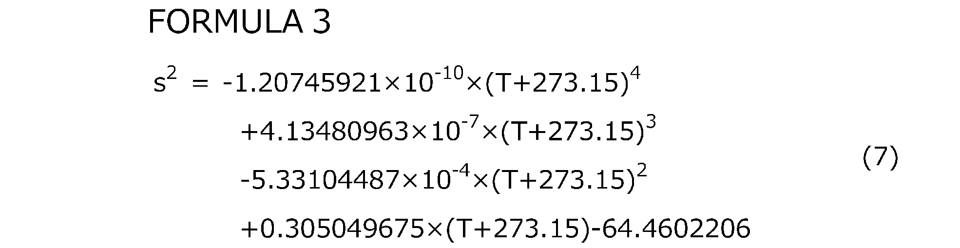
高温焼戻し工程を実施する場合、高温焼戻し工程では、焼入れされた中間鋼材(素管)を室温から保持温度まで加熱した後、保持温度で保持時間だけ保持する。高温焼戻し工程では、好ましい保持温度は640~740℃である。高温焼戻し工程における保持温度のさらに好ましい下限は645℃であり、さらに好ましくは650℃である。高温焼戻し工程における保持温度のさらに好ましい上限は730℃である。本実施形態による高温焼戻し工程では、好ましい保持時間は5~120分である。高温焼戻し工程における保持時間のさらに好ましい上限は100分である。高温焼戻し工程における保持時間のさらに好ましい下限は10分であり、さらに好ましくは20分である。
中温焼戻し工程では、中間鋼材(素管)を450~600℃で保持する。中温焼戻し工程では、450~600℃で保持することで、旧γ粒界にMoを濃化させる。このとき、好ましい保持時間は100分以上である。中温焼戻し工程の保持時間が短すぎれば、製造された鋼材において、粒界Mo量が十分に高められない場合がある。保持時間の上限は特に限定されないが、たとえば、8333時間であってもよい。


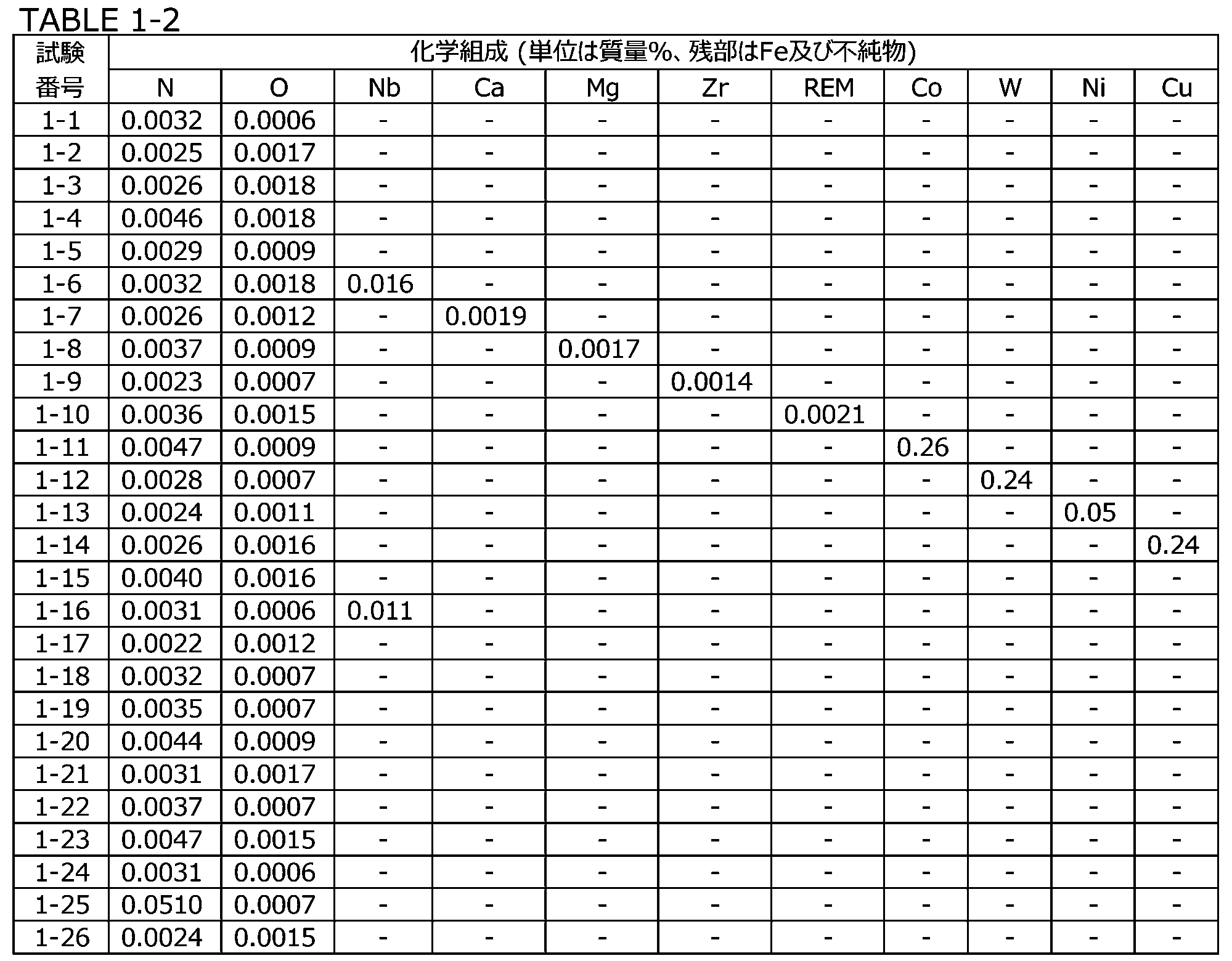

焼戻しが実施された試験番号1-1~1-26の鋼板に対して、以下に説明する引張試験、転位密度測定試験、粒界Mo量測定試験、DCB試験を実施した。
試験番号1-1~1-26の鋼板について、上述の方法により、引張試験を実施した。具体的に、試験番号1-1~1-26の鋼板の板厚中央部から、平行部直径4mm、標点距離16mmの丸棒引張試験片を作製した。丸棒引張試験片の軸方向は、鋼板の圧延方向と平行であった。試験番号1-1~1-26の丸棒試験片を用いて、常温(25℃)、大気中にて、ASTM E8/E8M(2021)に準拠した引張試験を実施して、試験番号1-1~1-26の鋼板の降伏強度(MPa)を得た。得られた降伏強度を「降伏強度σYS(MPa)」として表3に示す。
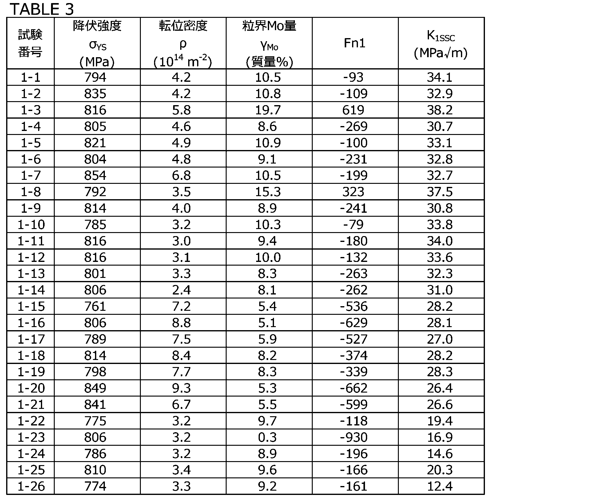
試験番号1-1~1-26の鋼板について、上述の方法により、転位密度測定試験を実施した。具体的に、試験番号1-1~1-26の鋼板の板厚中央部から、幅20mm×長さ20mm×厚さ2mmの試験片を作製した。上述の方法でX線回折法を用いて、(110)、(211)、(220)面のピークの半値幅ΔKを求めた。求めた半値幅ΔKを用いて、上述の方法で、転位密度ρ(m-2)を得た。得られた転位密度を「転位密度ρ(1014m-2)」として表3に示す。
試験番号1-1~1-26の鋼板について、上述の方法により、粒界Mo量測定試験を実施した。具体的に、試験番号1-1~1-26の鋼板の板厚t/4位置を中央に含み、圧延方向の長さ10mm×幅方向5mm×厚さ方向8mmの試験片を作製した。作製された試験片を用いて、上述の方法にて、粒界Mo量(質量%)を得た。得られた粒界Mo量を「粒界Mo量γMo(質量%)」として表3に示す。さらに、得られた降伏強度σYS(MPa)と、転位密度ρ(m-2)と、粒界Mo量γMo(質量%)と、式(1)とを用いて、Fn1を得た。得られたFn1を表3に示す。
試験番号1-1~1-26の鋼板について、上述の方法により、DCB試験を実施した。具体的に、試験番号1-1~1-26の鋼板の板厚中央部から、上述のDCB試験片及びクサビを作製した。作製された試験片及びクサビを用いて、上述の条件にて、NACE TM0177-2016 Method Dに準拠したDCB試験を実施した。以上の方法で実施したDCB試験により得られた破壊靭性値K1SSC値を「K1SSC(MPa√m)」として表3に示す。
表1-1、表1-2、表2、及び、表3を参照して、試験番号1-1~1-14の鋼板の化学組成は適切であり、降伏強度が758MPa以上(110ksi以上)であった。さらに、粒界Mo量γMoが5.0質量%以上であり、Fn1が-300以上であった。その結果、K1SSC値が29.5MPa以上となった。すなわち、これらの鋼板は、110ksi以上の降伏強度と、低温サワー環境での優れた破壊靭性とを有していた。
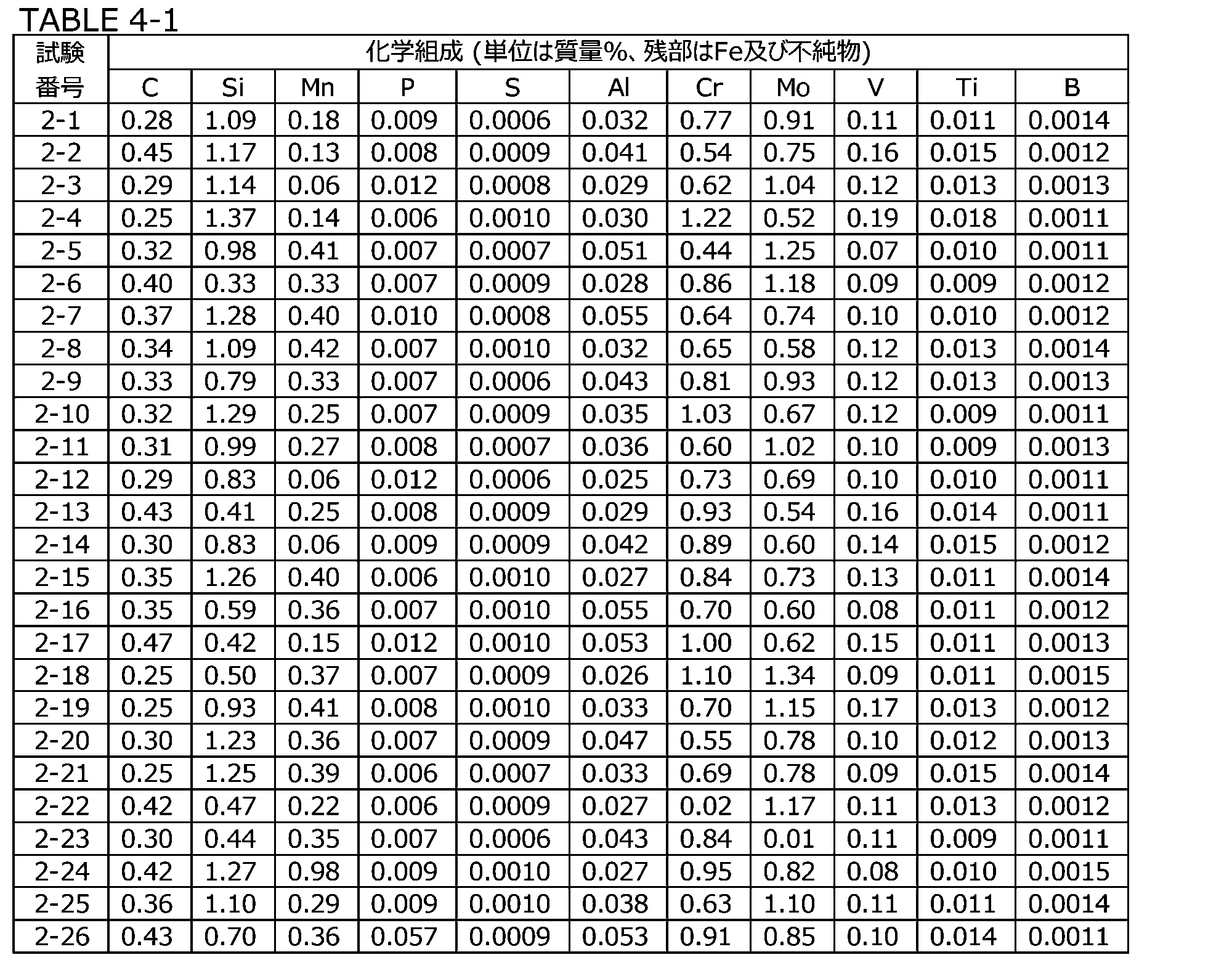


焼戻しが実施された試験番号2-1~2-26の鋼板に対して、以下に説明する引張試験、転位密度測定試験、粒界Mo量測定試験、DCB試験を実施した。
試験番号2-1~2-26の鋼板について、上述の方法により、引張試験を実施した。具体的に、試験番号2-1~2-26の鋼板の板厚中央部から、平行部直径4mm、標点距離16mmの丸棒引張試験片を作製した。丸棒引張試験片の軸方向は、鋼板の圧延方向と平行であった。試験番号2-1~2-26の丸棒試験片を用いて、常温(25℃)、大気中にて、ASTM E8/E8M(2021)に準拠した引張試験を実施して、試験番号2-1~2-26の鋼板の降伏強度(MPa)を得た。得られた降伏強度を「降伏強度σYS(MPa)」として表6に示す。

試験番号2-1~2-26の鋼板について、上述の方法により、転位密度測定試験を実施した。具体的に、試験番号2-1~2-26の鋼板の板厚中央部から、幅20mm×長さ20mm×厚さ2mmの試験片を作製した。上述の方法でX線回折法を用いて、(110)、(211)、(220)面のピークの半値幅ΔKを求めた。求めた半値幅ΔKを用いて、上述の方法で、転位密度ρ(m-2)を得た。得られた転位密度を「転位密度ρ(1014m-2)」として表6に示す。
試験番号2-1~2-26の鋼板について、上述の方法により、粒界Mo量測定試験を実施した。具体的に、試験番号2-1~2-26の鋼板の板厚t/4位置を中央に含み、圧延方向の長さ10mm×幅方向5mm×厚さ方向8mmの試験片を作製した。作製された試験片を用いて、上述の方法にて、粒界Mo量(質量%)を得た。得られた粒界Mo量を「粒界Mo量γMo(質量%)」として表6に示す。さらに、得られた降伏強度σYS(MPa)と、転位密度ρ(m-2)と、粒界Mo量γMo(質量%)と、式(1)とを用いて、Fn1を得た。得られたFn1を表6に示す。
試験番号2-1~2-26の鋼板について、上述の方法により、DCB試験を実施した。具体的に、試験番号2-1~2-26の鋼板の板厚中央部から、上述のDCB試験片及びクサビを作製した。作製された試験片及びクサビを用いて、上述の条件にて、NACE TM0177-2016 Method Dに準拠したDCB試験を実施した。以上の方法で実施したDCB試験により得られた破壊靭性値K1SSC値を「K1SSC(MPa√m)」として表6に示す。
表4-1、表4-2、表5、及び、表6を参照して、試験番号2-1~2-14の鋼板の化学組成は適切であり、降伏強度が862MPa以上(125ksi以上)であった。さらに、粒界Mo量γMoが5.0質量%以上であり、Fn1が-520以上であった。その結果、K1SSC値が24.1MPa以上となった。すなわち、これらの鋼板は、110ksi以上の降伏強度と、低温サワー環境での優れた破壊靭性とを有していた。
Claims (3)
- 鋼材であって、
質量%で、
C:0.20超~0.60%、
Si:0.05~2.00%、
Mn:0.02~0.60%、
P:0.025%以下、
S:0.0100%以下、
Al:0.005~0.100%、
Cr:0.20~1.50%、
Mo:0.35~1.50%、
V:0.01~0.60%、
Ti:0.002~0.050%、
B:0.0001~0.0050%、
N:0.0100%以下、
O:0.0100%以下、
Nb:0~0.030%、
Ca:0~0.0100%、
Mg:0~0.0100%、
Zr:0~0.0100%、
希土類元素:0~0.0100%、
Co:0~0.50%、
W:0~0.50%、
Ni:0~0.20%、
Cu:0~0.50%、及び、
残部がFe及び不純物からなり、
降伏強度σYSが758MPa以上であり、
前記鋼材中において、旧オーステナイト粒界近傍のMo含有量γMoが5.0質量%以上であり、
前記降伏強度σYSが862MPa未満の場合、式(1)で定義されるFn1が-300以上を満たし、
前記降伏強度σYSが862MPa以上の場合、式(1)で定義されるFn1が-520以上を満たす、
鋼材。
Fn1=83×(γMo-10-7×√ρ)-σYS (1)
ここで、式(1)中のγMoには前記旧オーステナイト粒界近傍のMo含有量が質量%で代入され、式(1)中のρには転位密度がm-2で代入され、式(1)中のσYSには前記降伏強度がMPaで代入される。 - 請求項1に記載の鋼材であって、
Nb:0.001~0.030%、
Ca:0.0001~0.0100%、
Mg:0.0001~0.0100%、
Zr:0.0001~0.0100%、
希土類元素:0.0001~0.0100%、
Co:0.01~0.50%、
W:0.01~0.50%、
Ni:0.01~0.20%、及び、
Cu:0.01~0.50%、からなる群から選択される1元素以上を含有する、
鋼材。 - 請求項1又は請求項2に記載の鋼材であって、
前記鋼材は、油井用鋼管である、鋼材。
Priority Applications (4)
| Application Number | Priority Date | Filing Date | Title |
|---|---|---|---|
| JP2024529960A JP7614555B1 (ja) | 2023-03-09 | 2024-02-13 | サワー環境での使用に適した鋼材 |
| EP24766783.5A EP4678774A4 (en) | 2023-03-09 | 2024-02-13 | STEEL MATERIAL SUITABLE FOR USE IN AN ACID SERVICE ENVIRONMENT |
| CN202480016078.4A CN120813717A (zh) | 2023-03-09 | 2024-02-13 | 适于在酸性环境下使用的钢材 |
| MX2025010517A MX2025010517A (es) | 2023-03-09 | 2025-09-05 | Material de acero adecuado para su uso en ambientes amargos |
Applications Claiming Priority (2)
| Application Number | Priority Date | Filing Date | Title |
|---|---|---|---|
| JP2023036280 | 2023-03-09 | ||
| JP2023-036280 | 2023-03-09 |
Publications (1)
| Publication Number | Publication Date |
|---|---|
| WO2024185411A1 true WO2024185411A1 (ja) | 2024-09-12 |
Family
ID=92674535
Family Applications (1)
| Application Number | Title | Priority Date | Filing Date |
|---|---|---|---|
| PCT/JP2024/004747 Ceased WO2024185411A1 (ja) | 2023-03-09 | 2024-02-13 | サワー環境での使用に適した鋼材 |
Country Status (6)
| Country | Link |
|---|---|
| EP (1) | EP4678774A4 (ja) |
| JP (1) | JP7614555B1 (ja) |
| CN (1) | CN120813717A (ja) |
| AR (1) | AR132058A1 (ja) |
| MX (1) | MX2025010517A (ja) |
| WO (1) | WO2024185411A1 (ja) |
Cited By (1)
| Publication number | Priority date | Publication date | Assignee | Title |
|---|---|---|---|---|
| WO2025215963A1 (ja) * | 2024-04-08 | 2025-10-16 | 日本製鉄株式会社 | 鋼材 |
Families Citing this family (1)
| Publication number | Priority date | Publication date | Assignee | Title |
|---|---|---|---|---|
| WO2025211036A1 (ja) * | 2024-04-01 | 2025-10-09 | 日本製鉄株式会社 | 鋼材 |
Citations (6)
| Publication number | Priority date | Publication date | Assignee | Title |
|---|---|---|---|---|
| JP2000297344A (ja) | 1999-04-09 | 2000-10-24 | Sumitomo Metal Ind Ltd | 靭性と耐硫化物応力腐食割れ性に優れる油井用鋼およびその製造方法 |
| JP2001271134A (ja) | 2000-03-24 | 2001-10-02 | Sumitomo Metal Ind Ltd | 耐硫化物応力割れ性と靱性に優れた低合金鋼材 |
| WO2008123422A1 (ja) | 2007-03-30 | 2008-10-16 | Sumitomo Metal Industries, Ltd. | 低合金鋼、油井用継目無鋼管および継目無鋼管の製造方法 |
| WO2010150915A1 (ja) * | 2009-06-24 | 2010-12-29 | Jfeスチール株式会社 | 耐硫化物応力割れ性に優れた油井用高強度継目無鋼管およびその製造方法 |
| JP2014012890A (ja) * | 2012-06-08 | 2014-01-23 | Jfe Steel Corp | 耐硫化物応力腐食割れ性に優れた油井用低合金高強度継目無鋼管およびその製造方法 |
| WO2019167945A1 (ja) * | 2018-02-28 | 2019-09-06 | 日本製鉄株式会社 | サワー環境での使用に適した鋼材 |
Family Cites Families (2)
| Publication number | Priority date | Publication date | Assignee | Title |
|---|---|---|---|---|
| MX379391B (es) * | 2014-11-18 | 2025-03-10 | Jfe Steel Corp | Tuberia sin costura de acero de alta resistencia para productos tubulares para la industria petrolera y metodo para producir la misma. |
| AR118071A1 (es) * | 2019-02-15 | 2021-09-15 | Nippon Steel Corp | Material de acero adecuado para uso en ambiente agrio |
-
2024
- 2024-02-13 JP JP2024529960A patent/JP7614555B1/ja active Active
- 2024-02-13 EP EP24766783.5A patent/EP4678774A4/en active Pending
- 2024-02-13 CN CN202480016078.4A patent/CN120813717A/zh active Pending
- 2024-02-13 WO PCT/JP2024/004747 patent/WO2024185411A1/ja not_active Ceased
- 2024-03-05 AR ARP240100548A patent/AR132058A1/es unknown
-
2025
- 2025-09-05 MX MX2025010517A patent/MX2025010517A/es unknown
Patent Citations (6)
| Publication number | Priority date | Publication date | Assignee | Title |
|---|---|---|---|---|
| JP2000297344A (ja) | 1999-04-09 | 2000-10-24 | Sumitomo Metal Ind Ltd | 靭性と耐硫化物応力腐食割れ性に優れる油井用鋼およびその製造方法 |
| JP2001271134A (ja) | 2000-03-24 | 2001-10-02 | Sumitomo Metal Ind Ltd | 耐硫化物応力割れ性と靱性に優れた低合金鋼材 |
| WO2008123422A1 (ja) | 2007-03-30 | 2008-10-16 | Sumitomo Metal Industries, Ltd. | 低合金鋼、油井用継目無鋼管および継目無鋼管の製造方法 |
| WO2010150915A1 (ja) * | 2009-06-24 | 2010-12-29 | Jfeスチール株式会社 | 耐硫化物応力割れ性に優れた油井用高強度継目無鋼管およびその製造方法 |
| JP2014012890A (ja) * | 2012-06-08 | 2014-01-23 | Jfe Steel Corp | 耐硫化物応力腐食割れ性に優れた油井用低合金高強度継目無鋼管およびその製造方法 |
| WO2019167945A1 (ja) * | 2018-02-28 | 2019-09-06 | 日本製鉄株式会社 | サワー環境での使用に適した鋼材 |
Non-Patent Citations (1)
| Title |
|---|
| See also references of EP4678774A1 |
Cited By (1)
| Publication number | Priority date | Publication date | Assignee | Title |
|---|---|---|---|---|
| WO2025215963A1 (ja) * | 2024-04-08 | 2025-10-16 | 日本製鉄株式会社 | 鋼材 |
Also Published As
| Publication number | Publication date |
|---|---|
| JP7614555B1 (ja) | 2025-01-16 |
| EP4678774A4 (en) | 2026-03-11 |
| EP4678774A1 (en) | 2026-01-14 |
| AR132058A1 (es) | 2025-05-21 |
| JPWO2024185411A1 (ja) | 2024-09-12 |
| CN120813717A (zh) | 2025-10-17 |
| MX2025010517A (es) | 2025-10-01 |
Similar Documents
| Publication | Publication Date | Title |
|---|---|---|
| US12522904B2 (en) | Martensitic stainless steel material and method for producing martensitic stainless steel material | |
| JP7036238B2 (ja) | サワー環境での使用に適した鋼材 | |
| CA3039038A1 (en) | Steel material, oil-well steel pipe, and method for producing steel material | |
| EP3862453B1 (en) | Steel material suitable for use in sour environment | |
| JP7036237B2 (ja) | サワー環境での使用に適した鋼材 | |
| JP7614555B1 (ja) | サワー環境での使用に適した鋼材 | |
| JP7173362B2 (ja) | サワー環境での使用に適した鋼材 | |
| US20190376167A1 (en) | Steel Material and Method for Producing Steel Material | |
| JP7211554B2 (ja) | サワー環境での使用に適した鋼材 | |
| JP6981527B2 (ja) | サワー環境での使用に適した鋼材 | |
| US11174539B2 (en) | Steel material suitable for use in sour environment | |
| WO2023204294A1 (ja) | 鋼材 | |
| JP2025110947A (ja) | ステンレス鋼材 | |
| JP7486012B1 (ja) | サワー環境での使用に適した鋼材 | |
| JP7564499B1 (ja) | 鋼材 | |
| JP7364993B1 (ja) | 鋼材 | |
| JP7832579B2 (ja) | 鋼材 | |
| JP7741467B1 (ja) | マルテンサイト系ステンレス鋼材 | |
| JP7832578B2 (ja) | 鋼材 | |
| JP2025080084A (ja) | サワー環境での使用に適した鋼材 | |
| JP2025080085A (ja) | サワー環境での使用に適した鋼材 | |
| WO2024147238A1 (ja) | サワー環境での使用に適した鋼材 | |
| WO2024214486A1 (ja) | 鋼材 | |
| JP2024125075A (ja) | 鋼材 | |
| JP2024137052A (ja) | 鋼材 |
Legal Events
| Date | Code | Title | Description |
|---|---|---|---|
| WWE | Wipo information: entry into national phase |
Ref document number: 2024529960 Country of ref document: JP |
|
| 121 | Ep: the epo has been informed by wipo that ep was designated in this application |
Ref document number: 24766783 Country of ref document: EP Kind code of ref document: A1 |
|
| WWE | Wipo information: entry into national phase |
Ref document number: 202480016078.4 Country of ref document: CN |
|
| REG | Reference to national code |
Ref country code: BR Ref legal event code: B01A Ref document number: 112025017830 Country of ref document: BR |
|
| WWE | Wipo information: entry into national phase |
Ref document number: 202517085305 Country of ref document: IN |
|
| WWP | Wipo information: published in national office |
Ref document number: 202517085305 Country of ref document: IN |
|
| WWE | Wipo information: entry into national phase |
Ref document number: 2025125592 Country of ref document: RU Ref document number: 2024766783 Country of ref document: EP |
|
| NENP | Non-entry into the national phase |
Ref country code: DE |
|
| WWP | Wipo information: published in national office |
Ref document number: 202480016078.4 Country of ref document: CN |
|
| WWP | Wipo information: published in national office |
Ref document number: 2025125592 Country of ref document: RU |
|
| ENP | Entry into the national phase |
Ref document number: 2024766783 Country of ref document: EP Effective date: 20251009 |
|
| ENP | Entry into the national phase |
Ref document number: 2024766783 Country of ref document: EP Effective date: 20251009 |
|
| ENP | Entry into the national phase |
Ref document number: 2024766783 Country of ref document: EP Effective date: 20251009 |
|
| ENP | Entry into the national phase |
Ref document number: 2024766783 Country of ref document: EP Effective date: 20251009 |