WO2024190088A1 - 電磁式アクチュエータ及び燃料噴射装置 - Google Patents
電磁式アクチュエータ及び燃料噴射装置 Download PDFInfo
- Publication number
- WO2024190088A1 WO2024190088A1 PCT/JP2024/001800 JP2024001800W WO2024190088A1 WO 2024190088 A1 WO2024190088 A1 WO 2024190088A1 JP 2024001800 W JP2024001800 W JP 2024001800W WO 2024190088 A1 WO2024190088 A1 WO 2024190088A1
- Authority
- WO
- WIPO (PCT)
- Prior art keywords
- stator core
- armature
- axial direction
- valve body
- electromagnetic actuator
- Prior art date
- Legal status (The legal status is an assumption and is not a legal conclusion. Google has not performed a legal analysis and makes no representation as to the accuracy of the status listed.)
- Ceased
Links
Images


Classifications
-
- F—MECHANICAL ENGINEERING; LIGHTING; HEATING; WEAPONS; BLASTING
- F02—COMBUSTION ENGINES; HOT-GAS OR COMBUSTION-PRODUCT ENGINE PLANTS
- F02M—SUPPLYING COMBUSTION ENGINES IN GENERAL WITH COMBUSTIBLE MIXTURES OR CONSTITUENTS THEREOF
- F02M47/00—Fuel-injection apparatus operated cyclically with fuel-injection valves actuated by fluid pressure
- F02M47/02—Fuel-injection apparatus operated cyclically with fuel-injection valves actuated by fluid pressure of accumulator-injector type, i.e. having fuel pressure of accumulator tending to open, and fuel pressure in other chamber tending to close, injection valves and having means for periodically releasing that closing pressure
- F02M47/027—Electrically actuated valves draining the chamber to release the closing pressure
-
- F—MECHANICAL ENGINEERING; LIGHTING; HEATING; WEAPONS; BLASTING
- F02—COMBUSTION ENGINES; HOT-GAS OR COMBUSTION-PRODUCT ENGINE PLANTS
- F02M—SUPPLYING COMBUSTION ENGINES IN GENERAL WITH COMBUSTIBLE MIXTURES OR CONSTITUENTS THEREOF
- F02M63/00—Other fuel-injection apparatus having pertinent characteristics not provided for in groups F02M39/00 - F02M57/00 or F02M67/00; Details, component parts, or accessories of fuel-injection apparatus, not provided for in, or of interest apart from, the apparatus of groups F02M39/00 - F02M61/00 or F02M67/00; Combination of fuel pump with other devices, e.g. lubricating oil pump
- F02M63/0012—Valves
- F02M63/0014—Valves characterised by the valve actuating means
- F02M63/0015—Valves characterised by the valve actuating means electrical, e.g. using solenoid
- F02M63/0017—Valves characterised by the valve actuating means electrical, e.g. using solenoid using electromagnetic operating means
- F02M63/0021—Valves characterised by the valve actuating means electrical, e.g. using solenoid using electromagnetic operating means characterised by the arrangement of mobile armatures
- F02M63/0022—Valves characterised by the valve actuating means electrical, e.g. using solenoid using electromagnetic operating means characterised by the arrangement of mobile armatures the armature and the valve being allowed to move relatively to each other
-
- F—MECHANICAL ENGINEERING; LIGHTING; HEATING; WEAPONS; BLASTING
- F02—COMBUSTION ENGINES; HOT-GAS OR COMBUSTION-PRODUCT ENGINE PLANTS
- F02M—SUPPLYING COMBUSTION ENGINES IN GENERAL WITH COMBUSTIBLE MIXTURES OR CONSTITUENTS THEREOF
- F02M63/00—Other fuel-injection apparatus having pertinent characteristics not provided for in groups F02M39/00 - F02M57/00 or F02M67/00; Details, component parts, or accessories of fuel-injection apparatus, not provided for in, or of interest apart from, the apparatus of groups F02M39/00 - F02M61/00 or F02M67/00; Combination of fuel pump with other devices, e.g. lubricating oil pump
- F02M63/0012—Valves
- F02M63/007—Details not provided for in, or of interest apart from, the apparatus of the groups F02M63/0014 - F02M63/0059
- F02M63/0075—Stop members in valves, e.g. plates or disks limiting the movement of armature, valve or spring
-
- F—MECHANICAL ENGINEERING; LIGHTING; HEATING; WEAPONS; BLASTING
- F02—COMBUSTION ENGINES; HOT-GAS OR COMBUSTION-PRODUCT ENGINE PLANTS
- F02M—SUPPLYING COMBUSTION ENGINES IN GENERAL WITH COMBUSTIBLE MIXTURES OR CONSTITUENTS THEREOF
- F02M2200/00—Details of fuel-injection apparatus, not otherwise provided for
- F02M2200/08—Fuel-injection apparatus having special means for influencing magnetic flux, e.g. for shielding or guiding magnetic flux
Definitions
- the present disclosure relates to an electromagnetic actuator and a fuel injection device including the electromagnetic actuator.
- the armature and valve body are integrally formed, and the armature and valve body perform the same operation.
- the time that current is applied to the solenoid coil increases, the amount of movement of the armature increases and the amount of lift of the valve body also increases, but when the armature abuts against the stator core, a sudden movement in the valve closing direction occurs due to a repulsive force from the stator core.
- the valve body which had been performing a parabolic operation until then, begins to perform a sudden valve closing operation at the point when the armature abuts against the stator core, so the relationship between the current application time and the fuel injection amount changes from an upward gradient to a downward gradient, resulting in a problem of worsening controllability of the fuel injection.
- This disclosure has been made in consideration of the above-mentioned circumstances, and aims to prevent deterioration of fuel injection controllability by suppressing the sudden valve closing action that occurs in the valve body when the armature comes into contact with the stator core, as described above.
- one aspect of the electromagnetic actuator according to the present disclosure is an electromagnetic actuator provided in a fuel injection device, the actuator comprising: a stator core provided inside a casing of the fuel injection device and incorporating a coil that generates magnetic flux when energized; an armature having an opposing surface disposed opposite an end face of the stator core on one side of the casing in the axial direction, the armature having a first through hole extending along the axial direction, the armature being capable of reciprocating along the axial direction depending on the presence or absence of electromagnetic force generated from the stator core; and a coil that is inserted into the first through hole and that extends from the first through hole to the stator core.
- the valve body has a flange portion formed on a protrusion protruding toward the stator core side and has a diameter larger than the diameter of the first through hole, and is capable of opening and closing an outlet port of a back pressure chamber formed in the casing; and a first spring member that biases the valve body in a direction to close the outlet port along the axial direction.
- the valve body is slidably disposed along the axial direction when inserted into the first through hole, and the electromagnetic actuator is configured such that when the armature moves toward the stator core along the axial direction, the opposing surface of the armature abuts against the flange portion, causing the valve body to move in a direction to open the outlet port.
- One aspect of the fuel injection device disclosed herein is equipped with the electromagnetic actuator described above.
- the valve body is inserted into the first through hole and is arranged to be freely slidable along the axial direction relative to the armature. Therefore, when current is applied to the coil to inject fuel from the fuel injection hole into the combustion chamber, even if the armature abuts against the stator core and undergoes a sudden movement away from the stator core due to the repulsive force it receives from the stator core, the valve body can be prevented from performing a sudden valve closing movement in conjunction with the armature. This makes it possible to prevent deterioration of the controllability of the fuel injection.
- FIG. 1 is a schematic vertical cross-sectional view showing a fuel injection device according to one embodiment
- 2 is a vertical cross-sectional view showing an electromagnetic actuator according to an embodiment incorporated in the fuel injection device shown in FIG. 1
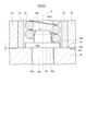
- FIG. 11 is an enlarged vertical cross-sectional view showing a portion of an electromagnetic actuator according to another embodiment.
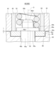
- FIG. 11 is an enlarged vertical cross-sectional view showing a portion of an electromagnetic actuator according to still another embodiment.
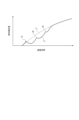
- 4 is a graph showing the relationship between the fuel injection amount and the time for which current is applied to a coil in a fuel injection device.
- expressions indicating that things are in an equal state such as “identical,””equal,” and “homogeneous,” not only indicate a state of strict equality, but also indicate a state in which there is a tolerance or a difference to the extent that the same function is obtained.
- expressions describing shapes such as a rectangular shape or a cylindrical shape do not only represent rectangular shapes or cylindrical shapes in the strict geometric sense, but also represent shapes that include uneven portions, chamfered portions, etc., to the extent that the same effect can be obtained.
- the expressions “comprise,””include,””have,””includes,” or “have” of one element are not exclusive expressions excluding the presence of other elements.
- FIG. 1 is a schematic vertical cross-sectional view showing an embodiment of a fuel injection device according to the present disclosure.
- Fig. 2 is a vertical cross-sectional view showing a part of the fuel injection device shown in Fig. 1, and shows an embodiment of an electromagnetic actuator according to the present disclosure.
- a fuel passage 14 is formed in a casing 12 of a fuel injection device 10.
- High-pressure fuel is supplied to the fuel passage 14 from a high-pressure fuel pipe (not shown), as indicated by arrow a.
- a high-pressure fuel pipe (not shown), as indicated by arrow a.
- common rail a pressure storage pipe
- surge tank a type of surge tank
- a first space S1 extending along the axis O of the casing 12 is formed inside the casing 12, and a spool 16 is disposed in the first space S1 .
- a piston 18 is provided on one end of the spool 16, and a needle valve 20 is provided on the other end.
- a plurality of injection holes 22 are formed in the tip of the casing 12, and the fuel passage 14 branches into a fuel passage 14a communicating with the injection holes 22 inside the casing 12, and a fuel passage 14b communicating with a back pressure chamber P formed facing the piston 18.
- the needle valve 20 reciprocates along the axis O together with the spool 16, thereby opening and closing the injection hole 22.
- High pressure fuel is injected from the opened injection hole 22 into a combustion chamber (not shown) of the internal combustion engine.
- the tip side of the casing 12 where the injection holes 22 are provided is defined as the X direction, and the direction opposite to the X direction is defined as the Y direction.
- An inlet orifice 25 communicating from the fuel passage 14b to the back pressure chamber P is formed inside the casing 12, a second space S2 is formed adjacent to the first space S1 on the Y direction side via a partition wall 12a, and an outlet orifice 24 communicating with the back pressure chamber P and the second space S2 is formed in the partition wall 12a.
- An electromagnetic actuator 40 according to an embodiment of the electromagnetic actuator according to the present disclosure is provided in the second space S2 to open and close the outlet orifice 24.
- a spring member 26 is provided in the axial center of the spool 16, one end of which is engaged with a step 28 formed on the inner wall of the casing 12 facing the first space S1 , and the other end of the spring member 26 is engaged with a support base 30 which is integral with the spool 16 and expands in the radial direction (hereinafter simply referred to as the "radial direction") of the casing 12.
- the spring member 26 applies a spring force to the spool 16 in a direction in which the needle valve 20 closes the injection hole 22.
- the electromagnetic actuator 40 closes the outlet orifice 24
- the spool 16 is in a position to close the injection hole 22.
- the back pressure chamber P communicates with the second space S2 , while the inflow of fuel from the fuel passage 14b is throttled (restricted) through the inlet orifice 25, reducing the fuel pressure in the back pressure chamber P.
- a leak passage 32 communicating with the first space S1 and the second space S2 is formed in the casing 12, and fuel leaking from the fuel passages 14a and 14b to the first space S1 flows from the first space S1 through the leak passage 32 into the second space S2. Then, the fuel is discharged from the second space S2 through an outlet 34 formed in the casing 12, as shown by the arrow b.
- the electromagnetic actuator 40 includes a stator core 42 provided in the second space S2 .
- the stator core 42 is made of a magnetic material and includes a solenoid coil 44.
- the solenoid coil 44 When the solenoid coil 44 is energized, the solenoid coil 44 generates a magnetic flux, and an electromagnetic force is generated from the stator core 42.
- an armature 46 is disposed on one side (the X-direction side in the embodiment shown in FIG. 2) of the stator core 42 in the axial direction (hereinafter also simply referred to as the "axial direction") of the casing 12.
- the armature 46 has an opposing surface 46a (the upper surface of the armature 46 in the embodiment shown in FIG.
- the armature 46 is disposed so as to be capable of reciprocating along the axial direction depending on the presence or absence of an electromagnetic force generated from the stator core 42. That is, when an electromagnetic force is generated from the stator core 42, the armature 46 is attracted to the stator core 42 along the axial direction.
- the electromagnetic actuator 40 further includes a valve body 48 and a first spring member 52.
- the valve body 48 is inserted into the first through hole 46b and is arranged to be freely slidable in the axial direction inside the first through hole 46b, and opens and closes the injection hole 22 by reciprocating in the axial direction.
- the valve body 48 also has a protrusion 48b arranged to protrude from the first through hole 46b toward the stator core 42, and the protrusion 48b has a flange 50 having a diameter larger than the diameter of the first through hole 46b.
- the protrusion 48b and the flange 50 are formed integrally with the valve body 48.
- the spring force of the first spring member 52 biases the valve body 48 in the axial direction in the direction (X direction) that closes the outlet orifice 24.
- valve opening operation When the armature 46 moves parallel to the stator core 42, the opposing surface 46a of the armature 46 abuts against the flange 50 because the flange 50 has a diameter larger than the first through hole 46b. As a result, the valve body 48, which is integral with the flange 50, also moves against the spring force of the first spring member 52 to open the outlet orifice 24 (valve opening operation).
- valve body 48 is arranged to be slidable along the axial direction relative to the armature 46 while inserted into the first through-hole 46b, so even if the armature 46 makes a sudden movement in a direction away from the stator core 42 due to the repulsive force generated when the armature 46 comes into contact with the stator core 42, the sudden movement is not directly transmitted to the valve body 48. Therefore, it is possible to prevent the valve body 48 from performing a sudden valve closing movement in conjunction with the armature 46, thereby preventing a deterioration in the controllability of the fuel injection.
- FIG. 5 is a graph showing the relationship between the time that current is applied to the solenoid coil 44 and the fuel injection amount in the fuel injection device 10 equipped with the electromagnetic actuator 40 and the fuel injection devices disclosed in Patent Documents 1 and 2.
- line L1 shows the fuel injection amount of the fuel injection device 10
- line L2 shows the fuel injection amount of the fuel injection devices disclosed in Patent Documents 1 and 2.
- the amount of movement (lift amount) of the valve body 48 toward the stator core 42 increases parabolic with increasing current application time until the armature 46 abuts against the stator core 42, and the fuel injection amount also increases approximately in proportion to the current application time.
- the armature 46 receives a repulsive force from the stator core 42 and moves abruptly in the valve closing direction. Therefore, as disclosed in Patent Documents 1 and 2, in a fuel injection device in which the armature and the valve body are integrally configured, the valve body 48 also moves abruptly in the valve closing direction, so that the fuel injection amount changes from increasing to suddenly decreasing as shown by line L2 . This causes a problem of deterioration in the controllability of the fuel injection.
- peaks f1, f2, and f3 of line L2 indicate the times when the armature comes into contact with the stator core.
- the fuel injection amount drops sharply after peaks f1, f2, and f3.
- the armature 46 and the valve body 48 are not integrated, and the valve body 48 is arranged slidably relative to the armature 46 while inserted into the first through-hole 46b, so that even if the opposing surface 46a of the armature 46 abuts against the opposing surface 42a of the stator core 42 and receives a repulsive force from the stator core 42, and the armature 46 makes a sudden movement in a direction away from the stator core 42, the sudden movement is not directly transmitted to the valve body 48. Therefore, the fuel injection amount maintains a smooth curve like line L1 and does not drop suddenly, so that deterioration of the controllability of the fuel injection can be suppressed.
- the first spring member 52, the armature 46, the first through hole 46b, the valve body 48, and the protrusion 48b including the flange portion 50 are arranged so that their axes coincide with the axis O.
- the opposing surfaces 42a and 46a of the stator core 42 and the armature 46 are formed as flat surfaces extending in a direction perpendicular to the axis O.
- the first spring member 52 is disposed on the axis O in a space formed in the center of the stator core 42, and is configured as a coil spring extending along the axial direction.
- the protrusion 48b is formed integrally with the valve body 48, has a cylindrical shape, and has a small diameter portion 48b1 smaller than the flange portion 50 and the shaft portion 48a of the valve body 48, which will be described later.
- the small diameter portion 48b1 is inserted into a space formed inside the first spring member 52.
- the flange portion 50 is formed between the protrusion 48b and the valve body 48, and is configured in a disk shape having a diameter larger than the small diameter portion 48b1 and the shaft portion 48a.
- the small diameter portion 48b1 and the flange portion 50 may be made of a magnetic or non-magnetic material. For example, if they are made of a wear-resistant material, wear can be suppressed.
- the first through hole 46b formed in the armature 46 has a circular cross section and is formed to extend in the axial direction on the axis O.
- the valve body 48 has a cylindrical shaft portion 48a arranged along the axial direction on the axis O, and the shaft portion 48a is inserted into the first through hole 46b and is arranged slidably inside the first through hole 46b.
- a protrusion 48c is formed at the tip of the valve body 48 on the side opposite the flange portion 50, which abuts or separates from a valve seat formed in the partition wall 12a that forms the outlet orifice 24 to open and close the outlet orifice 24.
- the armature 46 has a disk-like shape expanding radially outward from the first through hole 46b, and a leak hole 46d is formed in the expanding portion, penetrating the opposing surface 46a and the back surface 46c opposite the opposing surface 46a.
- the leaked fuel that has flowed from the first space S1 through the leak passage 32 into the second space S2 passes through the leak hole 46d and flows out from the discharge port 34 in the direction of the arrow b. It is not always necessary to form the leak hole 46d.
- a convex portion 64 having a protrusion amount t is formed on the opposing surface 46a of the armature 46, thereby forming a gap between the opposing surface 46a and the opposing surface 42a of the stator core 42, and the oil may flow out from this gap to the exhaust port 34.
- the back surface 46c of the armature 46 forms an inclined surface that is inclined toward the stator core 42 as it moves from the radial center of the armature 46 toward the radial outside. This allows the volume and weight of the armature 46 to be reduced.
- the outlet orifice 24 having a throttling function is provided as an opening that communicates with the back pressure chamber P and opens into the second space S2 , but an opening that does not have a throttling function may be formed.
- the electromagnetic actuator 40 includes a second spring member 54.
- the second spring member 54 biases the armature 46 in the axial direction toward the stator core 42, and is configured to have a spring force such that the valve body 48 (projection 48c) closes the outlet orifice 24 and the opposing surface 46a of the armature 46 abuts against the flange 50 when the solenoid coil 44 is not energized.
- valve body 48 when the solenoid coil 44 is not energized, the valve body 48 is biased by the spring force of the first spring member 52 in a direction in which the valve body 48 (projection 48c) closes the outlet orifice 24, so that the valve body 48 closes the outlet orifice 24.
- the spring force of the second spring member 54 biases the armature 46 toward the stator core 42, so that the opposing surface 46a of the armature that faces the stator core 42 is in contact with the opposing surface 50a of the flange 50.
- an anchor member 56 is provided for stably supporting the valve body 48.
- the anchor member 56 is disposed inside the casing 12, on the opposite side of the armature 46 from the stator core 42 in the axial direction, and has a second through hole 56a extending along the axial direction.
- the valve body 48 has a shaft portion 48a extending along the axial direction, and a portion of the shaft portion 48a protruding from the first through hole 46b to the opposite side to the stator core 42 is slidably inserted into the second through hole 56a.
- the second spring member 54 is disposed between a back surface 46c opposite to the opposing surface 46a of the armature 46 and a step portion 56c formed on an outer circumferential surface 56b of the anchor member 56.
- the shaft portion 48a of the valve body 48 protruding from the first through hole 46b to the side opposite the stator core 42 is inserted into the second through hole 56a of the anchor member 56 and is slidably supported by the anchor member 56, so that the valve body 48 is stably supported by the anchor member 56.
- the second spring member 54 is disposed between the back surface 46c opposite the opposing surface 46a of the armature 46 and a step portion 56c formed on the outer peripheral surface 56b of the anchor member 56, so that the second spring member 54 is stably supported between the armature 46 and the anchor member 56, and can accurately apply a spring force along the axial direction of the valve body 48 to the armature 46.
- the anchor member 56 has a small diameter portion 56d that extends from the back surface 46c toward the anchor member 56 side, centered on the axis O.
- the anchor member 56 has a small diameter portion 46e that is arranged on the armature 46 side in the axial direction, centered on the axis O.
- the second spring member 54 is composed of a coil spring that is arranged to surround the shaft portion 48a of the valve body 48 and the small diameter portions 46e and 56d. Because the second spring member 54 is composed of a coil spring, it is easy to arrange it around the small diameter portions 46e and 56d.
- the armature 46 has an annular flat surface 46f that is parallel to the opposing surface 46a (i.e. perpendicular to the axis O) and that surrounds the small diameter portion 46e, closer to the center than the back surface 46c.
- One end of the second spring member 54 is positioned so as to engage with the flat surface 46f, and is stably supported by the flat surface 46f.
- the outer peripheral surface 56b of the anchor member 56, the outer shape of the small diameter portion 46e, and the outer shape of the small diameter portion 56d of the anchor member 56 are all circular, which makes it easy to position the second spring member 54, which is made of a coil spring.
- the anchor member 56 is formed on the axially opposite side of the armature 46 with an expanded diameter portion 56e having a larger diameter than the outer circumferential surface 56b, and is formed integrally with the anchor member 56.
- An annular retaining nut 58 is disposed radially outward of the anchor member 56 so as to surround the anchor member 56, and the outer circumferential surface of the retaining nut 58 is screwed into the inner circumferential surface of the casing 12.
- the anchor member 56 is stably supported inside the casing 12 by the retaining nut 58.
- a fuel passage 60 communicating with the fuel passage 14 is formed in the expanded diameter portion 56e, and the fuel passage 60 communicates with the outlet orifice 24 via the back pressure chamber P.
- FIG. 3 is a partially enlarged vertical cross-sectional view showing an electromagnetic actuator 40A according to one embodiment.
- the first spring member 52 is positioned radially inward of the stator core 42, extends along the axial direction, and is positioned opposite the flange portion 50.
- the first spring member 52 is constituted by a coil spring, and an axial end of the coil spring is disposed so as to contact the opposing surface 50 b of the flange portion 50 .
- a cylindrical frame 62 is provided radially outside the first spring member 52 and radially inside the stator core 42, extending along the axial direction and surrounding the first spring member 52.
- a protrusion 64 is formed on the opposing surface 46a of the armature 46 at a position facing the end face of the frame 62, protruding from the opposing surface 46a toward the stator core 42.
- the electromagnetic actuator 40A has a protrusion 64 formed on the opposing surface 46a, the opposing surface 42a of the stator core 42 abuts the protrusion 64 against the stator core 42 when the valve body 48 opens. Therefore, the abutment portion of the armature 46 that abuts against the stator core 42 can be limited to the protrusion 64. If there is variation in the part of the armature 46 that abuts against the opposing surface 42a of the stator core 42, there is a risk of variation in the timing at which the armature 46 abuts against the stator core 42. In this embodiment, the abutment portion of the armature 46 that abuts against the stator core 42 can be limited to the protrusion 64, making it easier to manage the opening operation of the valve body 48.
- the protrusions 64 abut against the end face of the frame body 62, rather than against the stator core 42 made of a magnetic material, wear on the stator core 42 can be suppressed. Furthermore, because the protrusions 64 can be formed from the end face of the frame body 62 toward the radial center of the armature 46, the timing at which the armature 46 abuts against the stator core 42 can be made less susceptible to the inclination of the opposing surface 46a of the armature 46 with respect to the horizontal direction.
- the first spring member 52 is composed of a coil spring, which is arranged to surround the cylindrical small diameter portion 48b1, with the axis of the coil spring aligned with axis O.
- the frame body 62 has a cylindrical shape and extends along the axial direction, with the axis aligned with axis O. In this way, the first spring member 52 is arranged to surround the small diameter portion 48b1, and is positioned so that the small diameter portion 48b1 fits into the inner space, making it easy to position the first spring member 52.
- the protrusion 64 has a flat surface that protrudes by t toward the stator core 42 side beyond the opposing surface 46a of the armature 46.
- the protrusion 64 is formed not only in the region that abuts against the frame body 62, but also in the region that abuts against the opposing surface 50a of the flange portion 50 that faces the opposing surface 46a of the armature 46. That is, in the embodiment shown in FIG. 3, the protrusion 64 is formed in the region that faces the end surface of the frame body 62 radially outward from the upper end edge 46b1 of the first through hole 46b.
- the protrusion 64 is formed so that the protrusion amount t is the same over the entire region. Therefore, by determining the protrusion amount t of the protrusion 64, the clearance between the opposing surface 46a of the armature 46 and the opposing surface 42a of the stator core 42 is also determined, and there is no need to separately manage this clearance.
- the protrusion amount t may be a height in microns.
- the protrusion 64 may be formed only in a region of the facing surface 46 a of the armature 46 that comes into contact with the end surface of the frame 62 at the very least.
- a gap is formed between the opposing surface 42a of the stator core 42 and the opposing surface 46a of the armature 46. This makes it possible to prevent poor response due to magnetism remaining in the armature 46 after the current flow to the solenoid coil 44 is stopped. Therefore, when the current flow to the solenoid coil 44 is stopped, the armature 46 can immediately start moving away from the opposing surface 42a of the stator core 42.
- FIG. 4 is a partially enlarged longitudinal sectional view showing an electromagnetic actuator 40B according to another embodiment.
- the first spring member 52 is disposed radially inside the stator core 42, extends along the axial direction, and is disposed so as to face the flange portion 50.
- a cylindrical frame body 62 is provided radially outside the first spring member 52 and radially inside the stator core 42, extending along the axial direction and surrounding the first spring member 52.
- An annular recess 66 is formed in the facing surface 46a facing the frame body 62, and a spacer 68 is fitted into the recess 66.
- the facing surface 68a of the spacer 68 facing the stator core 42 protrudes by t toward the stator core 42 from the facing surface 46a of the armature 46, and the facing surface 68a of the spacer 68 is disposed facing the axial end surface of the frame body 62.
- the opposing surface 68a of the spacer 68 protrudes by t toward the stator core 42 from the opposing surface 46a of the armature 46, so that the contact portion where the armature 46 contacts the stator core 42 when the valve is opened can be limited to the opposing surface 68a of the spacer 68.
- the spacer 68 contacts the end surface of the frame body 62, rather than the stator core 42 made of a magnetic material, wear of the stator core 42 can be suppressed.
- the spacer 68 is formed at a position opposite the frame body 62, it can be formed in the center region of the opposing surface 46a of the armature 46. This makes it possible to make the timing at which the armature 46 contacts the stator core 42 less susceptible to the inclination of the armature 46 with respect to the horizontal direction.
- the recess 66 is formed not only in the region of the opposing surface 46a of the armature 46 that abuts against the frame body 62, but also extends to the radially inner region until it reaches the first through hole 46b. That is, the spacer 68 is formed in the region facing the end face of the frame body 62 from the upper end edge 46b1 of the first through hole 46b toward the radially outer side. The spacer 68 is also formed in an annular shape so as to fill the entire region formed by the recess 66 in accordance with the shape of the recess 66, and the inner peripheral surface of the spacer 68 is formed so as to face and be adjacent to the outer peripheral surface of the shaft portion 48a.
- the recess 66 extends until it reaches the first through hole 46b, so that the machining of the recess 66 is easy. At the very least, the recess 66 needs to be formed only on the opposing surface 46a that abuts against the end surface of the frame 62, and the spacer 68 also needs to be formed so as to fit into the annular recess thus formed.
- the outer peripheral surface of the recess 66 has a circular shape, and the bottom surface forms a flat surface having the same depth as the entire radial direction. Since the recess 66 has such a shape, it is easy to process. In addition, the spacer 68 manufactured to match this shape is also easy to manufacture. Additionally, in the exemplary embodiment, spacer 68 is removably fitted into recess 66 so that spacer 68 can be replaced with a new spacer when it exceeds a certain allowable amount of wear. Furthermore, if the spacer 68 is made of a material that is more wear-resistant than the armature 46 made of a magnetic material, wear of the spacer 68 can be suppressed.
- An electromagnetic actuator is an electromagnetic actuator (40) provided in a fuel injection device (10), comprising: a stator core (42) provided inside a casing (12) of the fuel injection device (10) and incorporating a coil (44) that generates a magnetic flux when energized; an armature (46) having an opposing surface (46a) arranged opposite an end face (42a) on one side of the axial direction of the casing (12) in the stator core (42) and having a first through hole (46b) extending along the axial direction, the armature (46) being capable of reciprocating along the axial direction depending on the presence or absence of electromagnetic force generated from the stator core (42); and a protrusion
- the valve body (48) has a flange portion (50) having a diameter larger than the diameter of the first through hole (46b) formed in the casing (12), and the valve body (48) can open and close the outlet port (24) of the back pressure chamber (P) formed in the casing (12), and a first spring member (52) that
- the valve body (48) is arranged to be slidable along the axial direction when inserted into the first through hole (46b), and the electromagnetic actuator (40) is configured such that when the armature (46) moves toward the stator core (42) along the axial direction, the opposing surface (46a) of the armature (46) abuts against the flange portion (50), so that the valve body (48) moves in the direction of opening the outlet port (24).
- valve body (48) is inserted into the first through hole (46b) and is arranged to be slidable along the axial direction relative to the armature (46), so that the valve body (48) can be prevented from suddenly closing the valve in conjunction with the armature (46). This makes it possible to prevent the controllability of the fuel injection from deteriorating.
- Another aspect of the electromagnetic actuator (40) is the electromagnetic actuator (40) described in 1), which further includes a second spring member (54) that biases the armature (46) toward the stator core (42) along the axial direction, and the second spring member (54) is configured to have a spring force such that, when the coil (44) is not energized, the valve body (48) closes the outlet port (24) and the opposing surface (46a) of the armature (46) abuts against the flange portion (50).
- the valve body (48) receives the spring force of the first spring member (52) to close the outlet port (24).
- the spring force of the second spring member (54) is applied to the armature (46), so that the armature (46) is pulled toward the stator core (42) and the opposing surface (46a) of the armature (46) facing the stator core (42) is in contact with the flange portion (50).
- the electromagnetic actuator (40A) is the electromagnetic actuator (40) described in 1) or 2), in which the first spring member (52) is disposed radially inward of the stator core (42), extends along the axial direction, and is disposed so as to face the flange portion (50).
- the electromagnetic actuator (40A) further includes a cylindrical frame body (62) disposed between the first spring member (52) and the stator core (42), extends along the axial direction, and is disposed so as to surround the first spring member (52).
- the opposing surface (46a) of the armature (46) has a protrusion (64) formed at a position opposing an end face of the frame body (62) so as to protrude from the opposing surface (46a) toward the stator core (42).
- the abutment portion of the armature (46) against the stator core (42) can be limited to the convex portion (64). If there is variation in the portion of the armature (46) that abuts against the stator core (42), there is a risk of variation in the timing at which the armature (46) abuts against the stator core (42). With the above configuration, the abutment portion of the armature (46) against the stator core (42) can be limited to the convex portion (64), making it easier to manage the opening operation of the valve body (48).
- the convex portion (64) abuts against the end face of the frame body (62) rather than the stator core (42) made of a magnetic material, wear of the stator core (42) can be suppressed. Furthermore, since the convex portion (64) is formed at a position facing the frame body (62), it can be formed on the radial center side of the armature (46). Therefore, compared to when the protrusions (64) are formed on the radial periphery of the armature (46), the timing at which the armature (46) abuts against the stator core (42) is less affected by the inclination of the armature (46) relative to the horizontal direction.
- An electromagnetic actuator (40B) is the electromagnetic actuator (40) according to 1) or 2), in which the first spring member (52) is disposed radially inward of the stator core (42), extends along the axial direction, and is disposed so as to face the flange portion (50).
- the electromagnetic actuator (40B) includes a cylindrical frame body (62) disposed between the first spring member (52) and the stator core (42), extends along the axial direction, and is disposed so as to surround the first spring member (52), and an annular spacer (68) fitted into an annular recess (66) formed in the opposing surface (46a) of the armature (46), the spacer (68) protruding toward the stator core (42) from the opposing surface (46a) of the armature (46) at least at a position facing the end face of the frame body.
- the abutment portion of the armature (46) against the stator core (42) during the valve opening operation can be limited to the spacer (68), eliminating variation in the timing at which the armature (46) abuts against the stator core (42), making it easier to manage the valve opening operation of the valve body (48).
- the spacer (68) abuts against the frame body (62) rather than the stator core (42) made of a magnetic material, wear of the stator core (42) can be suppressed.
- the spacer (68) is formed at a position facing the frame body (62), it can be formed on the radial center side of the armature (46).
- the timing at which the armature (46) abuts against the stator core (42) can be less affected by the inclination of the armature (46) with respect to the horizontal direction.
- the electromagnetic actuator (40) is the electromagnetic actuator (40) described in 2), further comprising an anchor member (56) arranged inside the casing (12) on the opposite side of the stator core (42) with respect to the armature (46), the anchor member (56) having a second through hole (56a) extending along the axial direction into which the shaft portion (48a) of the valve body (48) protruding from the first through hole (46b) to the opposite side of the stator core (42) is inserted, and the second spring member (54) is arranged between a surface (46c) of the armature (46) opposite the opposing surface (46a) and a step portion (56c) formed on the outer circumferential surface (56b) of the anchor member (46).
- the shaft portion (48a) of the valve body (48) protruding from the first through hole (46b) to the opposite side of the stator core (42) is inserted into the second through hole (56a) of the anchor member (56) and slidably supported by the anchor member (56). Therefore, the valve body (48) is stably supported by the anchor member (56) while performing the valve opening and closing operations.
- the second spring member (54) is interposed between the surface (56c) opposite the opposing surface (46a) of the armature (46) and the step portion (56c) formed on the outer peripheral surface (56b) of the anchor member (56). Therefore, the second spring member (54) can be stably disposed between the armature (46) and the anchor member (56), and the spring force along the axial direction of the valve body (48) can be accurately applied to the armature (46).
- a fuel injection device (10) includes an electromagnetic actuator (40) described in any one of 1) to 5).
- one aspect of the fuel injection device includes an electromagnetic actuator (40) having the above-described configuration. Therefore, when current is applied to the coil (44) to inject fuel from the fuel injection hole (22) into the combustion chamber, even if the armature (46) abuts against the stator core (42) and undergoes a sudden movement away from the stator core (42) due to the repulsive force it receives from the stator core (42), the valve body (48) is inserted into the first through hole (46b) and is disposed so as to be freely slidable along the axial direction relative to the armature (46), and therefore the valve body (48) can be prevented from performing a sudden valve closing movement in conjunction with the armature (46). This can prevent the controllability of the fuel injection from deteriorating.
Landscapes
- Engineering & Computer Science (AREA)
- Chemical & Material Sciences (AREA)
- Combustion & Propulsion (AREA)
- Mechanical Engineering (AREA)
- General Engineering & Computer Science (AREA)
- Physics & Mathematics (AREA)
- Electromagnetism (AREA)
- Fluid Mechanics (AREA)
- Fuel-Injection Apparatus (AREA)
- Magnetically Actuated Valves (AREA)
Abstract
本開示に係る電磁式アクチュエータの一態様は、燃料噴射装置のケーシングの内部に設けられ、通電されると磁束を発生するコイルを内蔵したステータコアと、ステータコアにおけるケーシングの軸線方向の一方側の端面に対向して配置される対向面を有するとともに、軸線方向に沿って延在する第1貫通孔を有するアーマチャであって、ステータコアから発生する電磁力の有無によって軸線方向に沿って往復動可能なアーマチャと、第1貫通孔に挿入されるとともに第1貫通孔からステータコア側に突出した突出部に形成された第1貫通孔の径より大径の鍔部を有する弁体であって、ケーシングに形成された背圧室の出口ポートを開閉可能な弁体と、弁体を軸線方向に沿って前記出口ポートを閉止する方向に付勢する第1バネ部材と、を備える。
Description
本開示は電磁式アクチュエータ及びこの電磁式アクチュエータを備える燃料噴射装置に関する。
本願は、2023年3月10日に日本国特許庁に出願された特願2023-037974号に基づき優先権を主張し、その内容をここに援用する。
本願は、2023年3月10日に日本国特許庁に出願された特願2023-037974号に基づき優先権を主張し、その内容をここに援用する。
ディーゼル機関における燃料噴射システムは、コモンレールを初めとして電子制御方式が広く普及している。電子制御方式の燃料噴射システムにおいては、高速応答電磁弁が採用されて燃料の噴射制御が行われる事例が多い。このような電磁弁は、一般的な構造として、ソレノイドコイルを内蔵したステータコアに対向して磁性体で構成されるアーマチャが配置され、ソレノイドコイルに通電することで発生する電磁力でアーマチャを引き上げると共に、アーマチャに接続された弁体を持ち上げて燃料通路を開放するように構成されている。特許文献1及び2には、上述のような構成を有する燃料噴射装置が開示されている。
特許文献1及び2に開示された燃料噴射装置は、アーマチャと弁体とが一体に形成され、アーマチャと弁体とは同じ動作を行う。ソレノイドコイルに通電する時間が増加すると、アーマチャの動き量が増大すると共に弁体のリフト量も増加するが、アーマチャがステータコアに当接すると、ステータコアから反発力を受けて閉弁方向に向かう急峻な動きが発生する。そのため、それまで放物的な動作をしていた弁体は、アーマチャがステータコアに当接した時点で急峻的な閉弁動作に向かうため、通電時間に対する燃料噴射量の関係が上り勾配から下り勾配となり、燃料噴射の制御性が悪化するという問題がある。
本開示は、上述する事情に鑑みてなされたもので、上述のように、アーマチャがステータコアに当接した時に弁体に発生する急峻的な閉弁動作を抑制することによって、燃料噴射の制御性が悪化するのを抑制することを目的とする。
上記目的を達成するため、本開示に係る電磁式アクチュエータの一態様は、燃料噴射装置に設けられる電磁式アクチュエータであって、前記燃料噴射装置のケーシングの内部に設けられ、通電されると磁束を発生するコイルを内蔵したステータコアと、前記ステータコアにおける前記ケーシングの軸線方向の一方側の端面に対向して配置される対向面を有するとともに、前記軸線方向に沿って延在する第1貫通孔を有するアーマチャであって、前記ステータコアから発生する電磁力の有無によって前記軸線方向に沿って往復動可能なアーマチャと、前記第1貫通孔に挿入されるとともに前記第1貫通孔から前記ステータコア側に突出した突出部に形成された前記第1貫通孔の径より大径の鍔部を有する弁体であって、前記ケーシングに形成された背圧室の出口ポートを開閉可能な弁体と、前記弁体を前記軸線方向に沿って前記出口ポートを閉止する方向に付勢する第1バネ部材と、を備え、前記弁体は、前記第1貫通孔に挿入された状態において前記軸線方向に沿って摺動自在に配置され、前記電磁式アクチュエータは、前記アーマチャが前記軸線方向に沿って前記ステータコア側に移動する際に、前記アーマチャの前記対向面が前記鍔部に当接することで、前記弁体は前記出口ポートを開放する方向に移動するように構成される。
本開示に係る燃料噴射装置の一態様は、上述の電磁式アクチュエータを備える。
本開示に係る電磁式アクチュエータ及び燃料噴射装置の一態様によれば、弁体は、第1貫通孔に挿入されてアーマチャに対して軸線方向に沿って摺動自在に配置されているため、燃料噴射孔から燃焼室に燃料を噴射するためにコイルに通電された時、アーマチャがステータコアに当接してステータコアから受ける反発力によって、アーマチャがステータコア側から離れる方向へ急峻的な動作を行っても、弁体がアーマチャと連動して急峻的な閉弁動作を起こすのを抑制できる。これによって、燃料噴射の制御性が悪化するのを抑制できる。
以下、添付図面を参照して、本発明の幾つかの実施形態について説明する。ただし、これらの実施形態に記載されている又は図面に示されている構成部品の寸法、材質、形状及びその相対的配置等は、本発明の範囲をこれに限定する趣旨ではなく、単なる説明例にすぎない。
例えば、「ある方向に」、「ある方向に沿って」、「平行」、「直交」、「中心」、「同心」或いは「同軸」等の相対的或いは絶対的な配置を表す表現は、厳密にそのような配置を表すのみならず、公差、若しくは、同じ機能が得られる程度の角度や距離をもって相対的に変位している状態も表すものとする。
例えば、「同一」、「等しい」及び「均質」等の物事が等しい状態であることを表す表現は、厳密に等しい状態を表すのみならず、公差、若しくは、同じ機能が得られる程度の差が存在している状態も表すものとする。
例えば、四角形状や円筒形状等の形状を表す表現は、幾何学的に厳密な意味での四角形状や円筒形状等の形状を表すのみならず、同じ効果が得られる範囲で、凹凸部や面取り部等を含む形状も表すものとする。
一方、一つの構成要素を「備える」、「具える」、「具備する」、「含む」、又は「有する」という表現は、他の構成要素の存在を除外する排他的な表現ではない。
例えば、「ある方向に」、「ある方向に沿って」、「平行」、「直交」、「中心」、「同心」或いは「同軸」等の相対的或いは絶対的な配置を表す表現は、厳密にそのような配置を表すのみならず、公差、若しくは、同じ機能が得られる程度の角度や距離をもって相対的に変位している状態も表すものとする。
例えば、「同一」、「等しい」及び「均質」等の物事が等しい状態であることを表す表現は、厳密に等しい状態を表すのみならず、公差、若しくは、同じ機能が得られる程度の差が存在している状態も表すものとする。
例えば、四角形状や円筒形状等の形状を表す表現は、幾何学的に厳密な意味での四角形状や円筒形状等の形状を表すのみならず、同じ効果が得られる範囲で、凹凸部や面取り部等を含む形状も表すものとする。
一方、一つの構成要素を「備える」、「具える」、「具備する」、「含む」、又は「有する」という表現は、他の構成要素の存在を除外する排他的な表現ではない。
(燃料噴射装置の構成)
図1は、本開示に係る燃料噴射装置の一実施形態を示す模式的縦断面図である。図2は、図1に図示された燃料噴射装置の一部を示す縦断面図であって、本開示に係る電磁式アクチュエータの一実施形態を示す縦断面図である。
図1は、本開示に係る燃料噴射装置の一実施形態を示す模式的縦断面図である。図2は、図1に図示された燃料噴射装置の一部を示す縦断面図であって、本開示に係る電磁式アクチュエータの一実施形態を示す縦断面図である。
図1において、燃料噴射装置10のケーシング12には燃料通路14が形成されている。燃料通路14には、高圧燃料配管(不図示)から、矢印aで示されるように、高圧の燃料が供給される。例えば、燃料噴射装置10がディーゼルエンジンに設けられるコモンレール式燃料噴射システムに適用される場合には、一種のサージタンクである、「コモンレール」と称される蓄圧配管に蓄圧された高圧燃料が燃料通路14に供給される。
ケーシング12の内部にはケーシング12の軸線Oに沿って延在する第1空間S1が形成され、第1空間S1にスプール16が配置されている。スプール16の一端側にピストン18が設けられ、他端側にニードル弁20が設けられている。ケーシング12の先端部には複数の噴射孔22が形成され、燃料通路14は、ケーシング12の内部で噴射孔22に連通する燃料通路14aと、ピストン18に面して形成された背圧室Pに連通する燃料通路14bとに分岐している。スプール16と共にニードル弁20が軸線Oに沿って往復動することにより、噴射孔22が開閉する。開放された噴射孔22から内燃機関の燃焼室(不図示)に高圧状態の燃料が噴射される。
なお、図1において、噴射孔22が設けられたケーシング12の先端側をX方向とし、X方向と反対方向をY方向としている。
なお、図1において、噴射孔22が設けられたケーシング12の先端側をX方向とし、X方向と反対方向をY方向としている。
ケーシング12の内部に燃料通路14bから背圧室Pに連通する入口オリフィス25が形成されており、第1空間S1のY方向側に隔壁12aを介して隣接する第2空間S2が形成され、隔壁12aに背圧室Pと第2空間S2とに連通する出口オリフィス24が形成されている。第2空間S2には、出口オリフィス24を開閉するために、本開示に係る電磁式アクチュエータの一実施形態に係る電磁式アクチュエータ40が設けられている。
第1空間S1において、スプール16の軸方向中央部にはバネ部材26が設けられ、バネ部材26の一端は第1空間S1に面するケーシング12の内側壁に形成された段部28に係止し、バネ部材26の他端はスプール16に一体に設けられ、ケーシング12の径方向(以下単に「径方向」とも言う。)に拡大した支持台30に係止している。バネ部材26は、ニードル弁20が噴射孔22を閉止する方向へスプール16にバネ力を付勢している。電磁式アクチュエータ40が出口オリフィス24を閉止しているとき、スプール16は噴射孔22を閉止する位置にある。
電磁式アクチュエータ40が出口オリフィス24を開放したとき、背圧室Pは第2空間S2と連通し、一方で、燃料通路14bからの燃料の流入は入口オリフィス25を介して絞られるため(制限されるため)、背圧室Pの燃料圧が減圧される。これによって、スプール16をX方向へ付勢する力が減少し、スプール16がY方向へ移動することで、噴射孔22が開口し、高圧燃料がエンジン(例えばディーゼルエンジンなど)の燃焼室に噴射される。ケーシング12には第1空間S1と第2空間S2とに連通するリーク通路32が形成され、燃料通路14a及び14bから第1空間S1に漏れた燃料は第1空間S1からリーク通路32を経て第2空間S2に流入する。そして、第2空間S2から、矢印bで示されるように、ケーシング12に形成された排出口34を介して排出される。
(電磁式アクチュエータの構成)
図2に示されるように、電磁式アクチュエータ40は、第2空間S2に設けられたステータコア42を備えている。ステータコア42は磁性体で構成され、ソレノイドコイル44を内蔵し、ソレノイドコイル44に通電されると、ソレノイドコイル44は磁束を発生し、ステータコア42から電磁力が発生する。さらに、ケーシング12の軸線方向(以下単に「軸線方向」とも言う。)においてステータコア42の一方側(図2に図示されている実施形態ではX方向側)にアーマチャ46が配置されている。アーマチャ46は、ステータコア42の一方側端面42a(図1に図示された実施形態では、ステータコア42の下面42a)に対向して配置される対向面46a(図1に図示された実施形態では、アーマチャ46の上面)、及び軸線方向に沿って延在する第1貫通孔46bを有している。アーマチャ46は、ステータコア42から発生する電磁力の有無によって軸線方向に沿って往復動可能に配置されている。即ち、ステータコア42から電磁力が発生すると、アーマチャ46は軸線方向に沿ってステータコア42に引き寄せられる。
図2に示されるように、電磁式アクチュエータ40は、第2空間S2に設けられたステータコア42を備えている。ステータコア42は磁性体で構成され、ソレノイドコイル44を内蔵し、ソレノイドコイル44に通電されると、ソレノイドコイル44は磁束を発生し、ステータコア42から電磁力が発生する。さらに、ケーシング12の軸線方向(以下単に「軸線方向」とも言う。)においてステータコア42の一方側(図2に図示されている実施形態ではX方向側)にアーマチャ46が配置されている。アーマチャ46は、ステータコア42の一方側端面42a(図1に図示された実施形態では、ステータコア42の下面42a)に対向して配置される対向面46a(図1に図示された実施形態では、アーマチャ46の上面)、及び軸線方向に沿って延在する第1貫通孔46bを有している。アーマチャ46は、ステータコア42から発生する電磁力の有無によって軸線方向に沿って往復動可能に配置されている。即ち、ステータコア42から電磁力が発生すると、アーマチャ46は軸線方向に沿ってステータコア42に引き寄せられる。
さらに、電磁式アクチュエータ40は、弁体48及び第1バネ部材52を備えている。弁体48は、第1貫通孔46bに挿入された状態で、第1貫通孔46bの内部で軸線方向に摺動自在に配置され、軸線方向に往復動することで噴射孔22を開閉する。また、弁体48は第1貫通孔46bからステータコア42側へ突出するように配置された突出部48bを有し、突出部48bは、第1貫通孔46bの直径より大きい径を有する鍔部50を有している。突出部48b及び鍔部50は弁体48と一体に形成されている。第1バネ部材52のバネ力は、弁体48を軸線方向に沿って出口オリフィス24を閉止する方向(X方向)へ付勢している。
このような構成において、ソレノイドコイル44に通電されない時、弁体48に付勢される第1バネ部材52のバネ力によって弁体48は出口オリフィス24を閉止する位置に保持されている(閉弁状態)。ソレノイドコイル44が通電され、ソレノイドコイル44から磁束が発生してステータコア42から電磁力が発生すると、アーマチャ46にはステータコア42側へ引っ張られる吸引力が付勢される。この吸引力によってアーマチャ46は軸線Oの延在方向に沿ってステータコア42側へ平行移動する。アーマチャ46がステータコア42側へ平行移動すると、鍔部50は第1貫通孔46bより大きな径を有するため、アーマチャ46の対向面46aが鍔部50に当接する。そのため、鍔部50と一体の弁体48も第1バネ部材52のバネ力に抗して出口オリフィス24を開放するように移動する(開弁動作)。
このように、弁体48は第1貫通孔46bに挿入された状態でアーマチャ46に対して軸線方向に沿って摺動可能に配置されているため、アーマチャ46がステータコア42に当接して発生する反発力によって、アーマチャ46がステータコア42側から離れる方向へ急峻的な動作を行っても、その急峻的な動作は弁体48には直接伝わらない。そのため、弁体48がアーマチャ46と連動して急峻的な閉弁動作を起こすのを抑制でき、これによって、燃料噴射の制御性が悪化するのを抑制できる。
図5は、電磁式アクチュエータ40を備える燃料噴射装置10、及び特許文献1及び2に開示された燃料噴射装置において、ソレノイドコイル44への通電時間と燃料噴射量との関係を示すグラフである。同図中、ラインL1は燃料噴射装置10の燃料噴射量を示し、ラインL2は特許文献1及び2に開示された燃料噴射装置の燃料噴射量を示している。
弁体48のステータコア42側への移動量(リフト量)は、アーマチャ46がステータコア42に当接するまでは、通電時間が増加するに伴って放物的に増加し、燃料噴射量も通電時間にほぼ比例して増加する。しかし、アーマチャ46の対向面46aがステータコア42の対向面42aに当接すると、アーマチャ46はステータコア42から反発力を受け、急峻的に閉弁方向へ向かう動作を行う。従って、特許文献1及び2に開示されているように、アーマチャと弁体とが一体に構成された燃料噴射装置では、弁体48も急峻的に閉弁方向へ向かう動作を行うため、ラインL2のように、燃料噴射量が増加から急激に減少に転じる。そのため、燃料噴射の制御性が悪化するという問題がある。
図5中、ラインL2のピークf1、f2及びf3は、アーマチャがステータコアに当接した時点を示す。ラインL2では、ピークf1、f2及びf3の後で燃料噴射量が急激に落ち込んでいる。
これに対して、本実施形態に係る燃料噴射装置10では、アーマチャ46と弁体48とは一体ではなく、弁体48は第1貫通孔46bの挿入された状態でアーマチャ46に対して摺動自在に配置されているため、アーマチャ46の対向面46aがステータコア42の対向面42aに当接してステータコア42から反発力を受け、アーマチャ46がステータコア42側から離れる方向へ急峻的な動作を行っても、その急峻的な動作は弁体48には直接伝わらない。そのため、燃料噴射量はラインL1のような滑らかな曲線を維持し、急激に落ち込まないため、燃料噴射の制御性が悪化するのを抑制できる。
図2に図示されている実施形態では、ケーシング12の内部で、第1バネ部材52、アーマチャ46、第1貫通孔46b、弁体48、及び鍔部50を含む突出部48bは、これらの軸線が軸線Oと一致するように配置されている。また、ステータコア42及びアーマチャ46の互いの対向面42a及び46aは軸線Oと直交する方向に延在する平坦面で形成されている。
また、第1バネ部材52はステータコア42の中心部に形成された空間で軸線O上に配置され、かつ軸線方向に沿って延在するコイルバネで構成されている。
突出部48bは弁体48と一体に形成され、円筒形状を有し、鍔部50及び弁体48の後述する軸部48aより小径の小径部48b1を有している。小径部48b1は第1バネ部材52の内側に形成された空間に挿入されている。鍔部50は突出部48bと弁体48との間に形成され、小径部48b1及び軸部48aより大径を有する円板形状に構成されている。小径部48b1及び鍔部50は、磁性体又は非磁性体で構成されてもよい。例えば、耐摩耗性材料で構成されていれば、摩耗を抑制できる。
突出部48bは弁体48と一体に形成され、円筒形状を有し、鍔部50及び弁体48の後述する軸部48aより小径の小径部48b1を有している。小径部48b1は第1バネ部材52の内側に形成された空間に挿入されている。鍔部50は突出部48bと弁体48との間に形成され、小径部48b1及び軸部48aより大径を有する円板形状に構成されている。小径部48b1及び鍔部50は、磁性体又は非磁性体で構成されてもよい。例えば、耐摩耗性材料で構成されていれば、摩耗を抑制できる。
また、図2に図示されている実施形態では、アーマチャ46に形成される第1貫通孔46bは、横断面が円形に形成され、軸線O上で軸線方向に延在するように形成されている。弁体48は、軸線O上で軸線方向に沿って配置された円筒形状の軸部48aを有し、軸部48aが第1貫通孔46bに挿入され、第1貫通孔46bの内部で摺動可能に配置されている。また、鍔部50とは反対側の弁体48の先端部には、出口オリフィス24を形成する隔壁12aに形成された弁座に当接又は離接して出口オリフィス24を開閉する突部48cが形成されている。
また、アーマチャ46は第1貫通孔46bから径方向外側に拡径する円板状の形状を有し、拡径部に対向面46aと対向面46aと反対側の裏面46cとに貫通するリーク孔46dが形成されている。第1空間S1からリーク通路32を通して第2空間S2に流入した漏れ燃料はリーク孔46dを通過して排出口34から矢印b方向へ流出する。
なお、リーク孔46dは必ずしも形成されていなくてもよい。リーク孔46dが形成されていない場合には、例えば、後述するように、アーマチャ46の対向面46aに突出量tを有する凸部64が形成されたことによって、対向面46aとステータコア42の対向面42aとの間に隙間が形成され、この隙間から排出口34へ流出させるようにしてもよい。
なお、リーク孔46dは必ずしも形成されていなくてもよい。リーク孔46dが形成されていない場合には、例えば、後述するように、アーマチャ46の対向面46aに突出量tを有する凸部64が形成されたことによって、対向面46aとステータコア42の対向面42aとの間に隙間が形成され、この隙間から排出口34へ流出させるようにしてもよい。
さらに、アーマチャ46の裏面46cは、アーマチャ46の径方向中心側から径方向外側へ向かうにつれてステータコア42側へ傾斜した傾斜面を形成している。これによって、アーマチャ46の容積及び重量を低減できる。
なお、本実施形態では、背圧室Pに連通して第2空間S2に開口する開口として絞り機能を有する出口オリフィス24を設けているが、絞り機能を有さない開口を形成するようにしてもよい。
一実施形態では、図2に図示されているように、電磁式アクチュエータ40は第2バネ部材54を備えている。第2バネ部材54は、アーマチャ46を軸線方向に沿ってステータコア42側の方向へ付勢し、ソレノイドコイル44が通電されていない状態において、弁体48(突部48c)が出口オリフィス24を閉止すると共に、アーマチャ46の対向面46aが鍔部50に当接するようなバネ力を有するように構成されている。
この実施形態では、ソレノイドコイル44が通電されていない時、弁体48には、弁体48(突部48c)が出口オリフィス24を閉鎖する方向に、第1バネ部材52のバネ力が付勢されているため、弁体48は出口オリフィス24を閉止している。加えて、第2バネ部材54のバネ力がアーマチャ46をステータコア42側に付勢するため、ステータコア42側に対向するアーマチャの対向面46aは鍔部50の対向面50aに当接した状態となる。この状態でソレノイドコイル44に通電されてステータコア42に電磁力が発生すると、アーマチャ46がステータコア42側に引き寄せられ、そのアーマチャ46の動きは即座に鍔部50に伝わって、鍔部50をステータコア42側へ移動させるため、弁体48の開弁動作を遅滞なく惹起させることができる。
図2に図示されている実施形態では、弁体48を安定して支持するためのアンカ部材56を備えている。アンカ部材56は、ケーシング12の内部において、軸線方向においてアーマチャ46に対してステータコア42と反対側に配置されると共に、軸線方向に沿って延在する第2貫通孔56aを有する。
弁体48は軸線方向に沿って延在する軸部48aを有し、軸部48aは、第1貫通孔46bからステータコア42とは反対側に突出した部位が第2貫通孔56aに摺動自在に挿入されている。第2バネ部材54は、アーマチャ46の対向面46aとは反対側の裏面46cと、アンカ部材56の外周面56bに形成された段部56cとの間に配置されている。
弁体48は軸線方向に沿って延在する軸部48aを有し、軸部48aは、第1貫通孔46bからステータコア42とは反対側に突出した部位が第2貫通孔56aに摺動自在に挿入されている。第2バネ部材54は、アーマチャ46の対向面46aとは反対側の裏面46cと、アンカ部材56の外周面56bに形成された段部56cとの間に配置されている。
この実施形態によれば、第1貫通孔46bからステータコア42とは反対側に突出した弁体48の軸部48aがアンカ部材56の第2貫通孔56aに挿入され、アンカ部材56によって摺動自在に支持されるため、弁体48はアンカ部材56によって安定して支持される。また、第2バネ部材54は、アーマチャ46の対向面46aとは反対側の裏面46cと、アンカ部材56の外周面56bに形成された段部56cとの間に配置されているため、アーマチャ46とアンカ部材56との間に安定して支持されると共に、アーマチャ46に対して弁体48の軸方向に沿うバネ力を正確に付勢することができる。
図2に図示されている実施形態では、アンカ部材56は軸線Oを中心として裏面46cからアンカ部材56側に向けて延在する小径部56dを有する。アンカ部材56は軸線Oを中心として軸線方向でアーマチャ46側に配置された小径部46eを有する。第2バネ部材54は弁体48の軸部48a及び小径部46e、56dを取り巻くよう配置されたコイルバネで構成されている。第2バネ部材54はコイルバネで構成されているため、小径部46e及び56dの周囲に配置するのが容易になる。
さらに、アーマチャ46には、裏面46cより中心側でかつ小径部46eの周辺に小径部46eを取り巻くように対向面46aと平行な(即ち軸線Oと直交する)環状の平面46fが形成されている。第2バネ部材54の一端は平面46fに係止するように配置されるため、平面46fによって安定して支持される。アンカ部材56の外周面56b、小径部46eの外形及びアンカ部材56の小径部56dの外形は円形を有しているため、コイルバネで構成された第2バネ部材54の配置が容易になる。
さらに、図2に図示されている実施形態では、アンカ部材56には、アーマチャ46に対して軸線方向反対側に形成され、外周面56bよりさらに大径を有する拡径部56eがアンカ部材56と一体に形成されている。そして、アンカ部材56の径方向外側には、アンカ部材56を取り巻くように環状のリテーニングナット58が配置され、リテーニングナット58の外周面はケーシング12の内周面と螺合している。アンカ部材56はリテーニングナット58によってケーシング12の内部で安定して支持される。また、拡径部56eには燃料通路14に連通する燃料通路60が形成され、燃料通路60は背圧室Pを介して出口オリフィス24と連通している。
図3は、一実施形態に係る電磁式アクチュエータ40Aを示す一部拡大縦断面図である。
図3に示されるように、本実施形態に係る電磁式アクチュエータ40Aは、第1バネ部材52がステータコア42の径方向内側に配置されると共に、軸線方向に沿って延在し、かつ鍔部50に対向するように配置されている。
図3に図示されている実施形態では、第1バネ部材52はコイルバネで構成され、コイルバネの軸線方向端部は鍔部50の対向面50bに接するように配置されている。
図3に示されるように、本実施形態に係る電磁式アクチュエータ40Aは、第1バネ部材52がステータコア42の径方向内側に配置されると共に、軸線方向に沿って延在し、かつ鍔部50に対向するように配置されている。
図3に図示されている実施形態では、第1バネ部材52はコイルバネで構成され、コイルバネの軸線方向端部は鍔部50の対向面50bに接するように配置されている。
第1バネ部材52の径方向外側であってかつステータコア42の径方向内側には、軸線方向に沿って延在し、かつ第1バネ部材52を囲むように筒状の枠体62が設けられている。そして、アーマチャ46の対向面46aには、枠体62の端面に対向する位置に対向面46aよりステータコア42側へ向かって突出するように形成された凸部64が形成されている。
電磁式アクチュエータ40Aは、対向面46aに凸部64が形成されているため、弁体48の開弁動作時に凸部64がステータコア42の対向面42aがステータコア42に当接する。従って、ステータコア42に当接するアーマチャ46の当接部を凸部64に限ることができる。ステータコア42の対向面42aに当接するアーマチャ46の部位にばらつきがあると、アーマチャ46がステータコア42に当接するタイミングにばらつきが発生するおそれがある。本実施形態では、アーマチャ46がステータコア42に当接する当接部を凸部64に限ることができるため、弁体48の開弁動作の管理が容易になる。
また、凸部64は磁性体からなるステータコア42ではなく枠体62の端面に当接するため、ステータコア42の摩耗を抑制できる。さらに、凸部64は枠体62の端面からアーマチャ46の径方向中心側に形成することができるため、アーマチャ46がステータコア42に当接するタイミングがアーマチャ46の対向面46aの水平方向に対する傾きの影響を受けにくくすることができる。
図3に示されている実施形態では、第1バネ部材52はコイルバネで構成され、このコイルバネは円筒形の小径部48b1を囲むように配置され、該コイルバネの軸線は軸線Oと一致するように配置されている。そして、枠体62は円筒形を有して軸線方向に沿って延在し、その軸線が軸線Oと一致するように配置されている。このように、第1バネ部材52は小径部48b1を囲むように配置され、内側空間に小径部48b1が入りこむように位置決めされるため、第1バネ部材52の位置決めが容易である。
さらに、凸部64は、アーマチャ46の対向面46aよりtだけステータコア42側に突出した平面を有している。図3に図示されている実施形態では、凸部64は、枠体62と当接する領域だけでなく、鍔部50のアーマチャ46の対向面46aに対向する対向面50aに当接する領域にも形成されている。即ち、図3に図示されている実施形態では、凸部64は、第1貫通孔46bの上端縁46b1から径方向外側へ向かって枠体62の端面に対向する領域に形成されている。
また、凸部64は、全領域で同じ突出量tとなるように形成されている。従って、凸部64の突出量tを決めれば、アーマチャ46の対向面46aとステータコア42の対向面42aとの間のクリアランスも決まるため、このクリアランスを別に管理する必要がなくなる。例えば、突出量tはミクロン単位の高さでもよい。
なお、別な実施形態では、凸部64は、アーマチャ46の対向面46aのうち、最低限枠体62の端面と当接する領域にのみ形成されてもよい。
なお、別な実施形態では、凸部64は、アーマチャ46の対向面46aのうち、最低限枠体62の端面と当接する領域にのみ形成されてもよい。
なお、凸部64を形成することで、ステータコア42の対向面42aとアーマチャ46の対向面46aとの間に隙間が形成される。これによって、ソレノイドコイル44への通電を停止した後、アーマチャ46に磁気が残留することによる応答不良を防止できる。そのため、ソレノイドコイル44への通電を停止すると、アーマチャ46がステータコア42の対向面42aから遠ざかる側への移動を即座に開始できる。
図4は、別な実施形態に係る電磁式アクチュエータ40Bを示す一部拡大縦断面図である。本実施形態において、第1バネ部材52がステータコア42の径方向内側に配置されると共に、軸線方向に沿って延在し、かつ鍔部50に対向するように配置されている。第1バネ部材52の径方向外側であってかつステータコア42の径方向内側には、軸線方向に沿って延在し、かつ第1バネ部材52を囲むように筒状の枠体62が設けられている。そして、枠体62に対向する対向面46aに環状の凹部66が形成され、凹部66にスペーサ68が嵌合されている。ステータコア42に対向するスペーサ68の対向面68aはアーマチャ46の対向面46aよりステータコア42側にtだけ突出して、枠体62の軸線方向端面にスペーサ68の対向面68aが対向して配置される。
この実施形態によれば、スペーサ68の対向面68aはアーマチャ46の対向面46aよりステータコア42側にtだけ突出しているため、開弁時にアーマチャ46がステータコア42に当接する当接部をスペーサ68の対向面68aに限ることができる。そのため、アーマチャ46がステータコア42に当接するタイミングのばらつきをなくすことができ、これによって、弁体48の開弁動作の管理が容易になる。また、スペーサ68は磁性体からなるステータコア42ではなく、枠体62の端面に当接するため、ステータコア42の摩耗を抑制できる。さらに、スペーサ68は枠体62に対向する位置に形成されるため、アーマチャ46の対向面46aの中心側領域に形成できる。そのため、アーマチャ46がステータコア42に当接するタイミングがアーマチャ46の水平方向に対する傾きの影響を受けにくくすることができる。
図4に図示されている実施形態では、凹部66は、アーマチャ46の対向面46aのうち枠体62に当接する領域だけでなく、径方向内側領域に延在し、第1貫通孔46bに達するまで形成されている。即ち、スペーサ68は、第1貫通孔46bの上端縁46b1から径方向外側へ向かって枠体62の端面に対向する領域に形成されている。そして、スペーサ68も凹部66の形状に合わせて凹部66が形成する全領域を埋めるように環状に形成され、スペーサ68の内周面が軸部48aの外周面に対向して隣接するように形成されている。この実施形態によれば、凹部66が第1貫通孔46bに達するまで延在しているため、凹部66の加工が容易になる。
なお、凹部66は最低限枠体62の端面に当接する対向面46aのみに形成さればよく、かつスペーサ68もそのように形成された環状の凹部に嵌合するように形成されればよい。
なお、凹部66は最低限枠体62の端面に当接する対向面46aのみに形成さればよく、かつスペーサ68もそのように形成された環状の凹部に嵌合するように形成されればよい。
図4に図示されている実施形態では、凹部66の外周面は円形を有し、かつ底面は全体として径方向で同一深さの平面を形成している。凹部66はこのような形状を有しているため、加工が容易である。また、この形状に合わせて製造されるスペーサ68の製造も容易になる。
また、例示的な実施形態では、スペーサ68を凹部66に着脱可能に嵌合する。これによって、スペーサ68が一定の許容される摩耗量を超えたときは、新しいスペーサと交換することができる。
また、スペーサ68が磁性体からなるアーマチャ46より耐摩耗性が良い材料で構成されていれば、スペーサ68の摩耗を抑制できる。
また、例示的な実施形態では、スペーサ68を凹部66に着脱可能に嵌合する。これによって、スペーサ68が一定の許容される摩耗量を超えたときは、新しいスペーサと交換することができる。
また、スペーサ68が磁性体からなるアーマチャ46より耐摩耗性が良い材料で構成されていれば、スペーサ68の摩耗を抑制できる。
上記各実施形態に記載の内容は、例えば以下のように把握される。
1)一態様に係る電磁式アクチュエータは、燃料噴射装置(10)に設けられる電磁式アクチュエータ(40)であって、前記燃料噴射装置(10)のケーシング(12)の内部に設けられ、通電されると磁束を発生するコイル(44)を内蔵したステータコア(42)と、前記ステータコア(42)における前記ケーシング(12)の軸線方向の一方側の端面(42a)に対向して配置される対向面(46a)を有するとともに、前記軸線方向に沿って延在する第1貫通孔(46b)を有するアーマチャ(46)であって、前記ステータコア(42)から発生する電磁力の有無によって前記軸線方向に沿って往復動可能なアーマチャ(46)と、前記第1貫通孔(46b)に挿入されるとともに前記第1貫通孔(46b)から前記ステータコア(42)側に突出した突出部(48b)に形成された前記第1貫通孔(46b)の径より大径の鍔部(50)を有する弁体(48)であって、前記ケーシング(12)に形成された背圧室(P)の出口ポート(24)を開閉可能な弁体(48)と、前記弁体(48)を前記軸線方向に沿って前記出口ポート(24)を閉止する方向に付勢する第1バネ部材(52)と、を備え、前記弁体(48)は、前記第1貫通孔(46b)に挿入された状態において前記軸線方向に沿って摺動自在に配置され、前記電磁式アクチュエータ(40)は、前記アーマチャ(46)が前記軸線方向に沿って前記ステータコア(42)側に移動する際に、前記アーマチャ(46)の前記対向面(46a)が前記鍔部(50)に当接することで、前記弁体(48)が前記出口ポート(24)を開放する方向に移動するように構成される。
このような構成によれば、コイル(44)に通電されない時、弁体(48)に付勢される第1バネ部材(52)のバネ力によって弁体(48)は出口ポート(24)を閉止している。この状態でコイル(44)に通電されるとステータコア(42)に電磁力が発生し、この電磁力によってアーマチャ(46)がステータコア(42)側へ引き寄せられる。アーマチャ(46)がステータコア(42)側へ引き寄せられると、アーマチャ(46)は鍔部(50)に当接して鍔部(50)をステータコア(42)側へ引き寄せるため、鍔部(50)と一体の弁体(48)は、第1バネ部材(52)のバネ力に抗して出口ポート(24)を開弁する。その時、アーマチャ(46)がステータコア(42)に当接して反発力を受け、ステータコア(42)側から離れる方向へ急峻的な動作を行っても、弁体(48)は第1貫通孔(46b)に挿入された状態でアーマチャ(46)に対して軸線方向に沿って摺動自在に配置されているため、弁体(48)がアーマチャ(46)と連動して急峻的な閉弁動作を起こすのを抑制できる。これによって、燃料噴射の制御性が悪化するのを抑制できる。
2)別な態様に係る電磁式アクチュエータ(40)は、1)に記載の電磁式アクチュエータ(40)において、前記アーマチャ(46)を前記軸線方向に沿って前記ステータコア(42)側の方向に付勢する第2バネ部材(54)をさらに備え、前記第2バネ部材(54)は、前記コイル(44)が通電されていない状態において、前記弁体(48)が前記出口ポート(24)を閉止するとともに、前記アーマチャ(46)の前記対向面(46a)が前記鍔部(50)に当接するようなバネ力を有するように構成される。
このような構成によれば、コイル(44)が通電されていない時、弁体(48)は第1バネ部材(52)のバネ力を受けて出口ポート(24)を閉止しているが、この状態で上記第2バネ部材(54)のバネ力がアーマチャ(46)に付勢されるため、アーマチャ(46)はステータコア(42)側に寄せられ、ステータコア(42)側に対向するアーマチャ(46)の対向面(46a)は鍔部(50)に当接した状態となる。この状態でコイル(44)が通電されてステータコア(42)に電磁力が発生し、この電磁力でアーマチャ(46)がステータコア(42)側に引き寄せられると、アーマチャ(46)の動きは即座に鍔部(50)に伝わって鍔部(50)を動かすと共に、鍔部(50)と一体の弁体(48)の開弁動作を遅滞なく惹起させることができる。
3)さらに別な態様に係る電磁式アクチュエータ(40A)は、1)又は2)に記載の電磁式アクチュエータ(40)において、前記第1バネ部材(52)は、前記ステータコア(42)の径方向内側に配置されるとともに前記軸線方向に沿って延在し、かつ前記鍔部(50)に対向するように配置され、前記電磁式アクチュエータ(40A)は、前記第1バネ部材(52)と前記ステータコア(42)との間に配置されるとともに前記軸線方向に沿って延在し、かつ前記第1バネ部材(52)を囲むように配置された筒状の枠体(62)をさらに備え、前記アーマチャ(46)の前記対向面(46a)は、前記枠体(62)の端面に対向する位置に前記対向面(46a)より前記ステータコア(42)側へ突出するように形成された凸部(64)を有する。
このような構成によれば、アーマチャ(46)がステータコア(42)に当接する当接部を上記凸部(64)に限ることができる。ステータコア(42)に当接するアーマチャ(46)の部位にばらつきがあると、アーマチャ(46)がステータコア(42)に当接するタイミングにばらつきが発生するおそれがある。上記構成によれば、アーマチャ(46)がステータコア(42)に当接する当接部を凸部(64)に限ることができるため、弁体(48)の開弁動作の管理が容易になる。また、上記凸部(64)は磁性体からなるステータコア(42)ではなく上記枠体(62)の端面に当接するため、ステータコア(42)の摩耗を抑制できる。さらに、凸部(64)は上記枠体(62)に対向する位置に形成されるため、アーマチャ(46)の径方向中心側に形成することができる。そのため、凸部(64)がアーマチャ(46)の径方向周辺側に形成される場合と比べて、アーマチャ(46)がステータコア(42)に当接するタイミングがアーマチャ(46)の水平方向に対する傾きの影響を受けにくくすることができる。
4)さらに別な態様に係る電磁式アクチュエータ(40B)は、1)又は2)に記載の電磁式アクチュエータ(40)において、前記第1バネ部材(52)は、前記ステータコア(42)の径方向内側に配置されるとともに前記軸線方向に沿って延在し、かつ前記鍔部(50)に対向するように配置され、電磁式アクチュエータ(40B)は、前記第1バネ部材(52)と前記ステータコア(42)との間に配置されるとともに前記軸線方向に沿って延在し、かつ前記第1バネ部材(52)を囲むように配置された筒状の枠体(62)と、前記アーマチャ(46)の前記対向面(46a)に形成された環状の凹部(66)に嵌合された環状のスペーサ(68)であって、少なくとも前記枠体の端面に対向する位置において前記アーマチャ(46)の前記対向面(46a)より前記ステータコア(42)側に突出しているスペーサ(68)と、を備える。
このような構成によれば、開弁動作時にアーマチャ(46)がステータコア(42)に当接する当接部を上記スペーサ(68)に限ることができるため、アーマチャ(46)がステータコア(42)に当接するタイミングのばらつきをなくすことができ、これによって、弁体(48)の開弁動作の管理が容易になる。また、スペーサ(68)は磁性体からなるステータコア(42)ではなく上記枠体(62)に当接するため、ステータコア(42)の摩耗を抑制できる。さらに、スペーサ(68)は上記枠体(62)に対向する位置に形成されるため、アーマチャ(46)の径方向中心側に形成することができる。そのため、スペーサ(68)がアーマチャ(46)の径方向周辺側に形成される場合と比べて、アーマチャ(46)がステータコア(42)に当接するタイミングがアーマチャ(46)の水平方向に対する傾きの影響を受けにくくすることができる。
5)さらに別な態様に係る電磁式アクチュエータ(40)は、2)に記載の電磁式アクチュエータ(40)において、前記ケーシング(12)の内部において前記アーマチャ(46)に対して前記ステータコア(42)の反対側に配置されたアンカ部材(56)であって、前記第1貫通孔(46b)から前記ステータコア(42)とは反対側に突出した前記弁体(48)の軸部(48a)が挿入される、前記軸線方向に沿って延在する第2貫通孔(56a)を有するアンカ部材(56)をさらに備え、前記第2バネ部材(54)は、前記アーマチャ(46)の前記対向面(46a)とは反対側の面(46c)と、前記アンカ部材(46)の外周面(56b)に形成された段部(56c)との間に配置されている。
このような構成によれば、第1貫通孔(46b)からステータコア(42)とは反対側に突出した弁体(48)の軸部(48a)が上記アンカ部材(56)の第2貫通孔(56a)に挿入され、アンカ部材(56)によって摺動可能に支持されるため、弁体(48)は開弁動作及び閉弁動作を行いながらアンカ部材(56)によって安定して支持される。また、第2バネ部材(54)は、アーマチャ(46)の対向面(46a)とは反対側の面(56c)と、アンカ部材(56)の外周面(56b)に形成された段部(56c)との間に介装されるため、アーマチャ(46)とアンカ部材(56)との間に安定して配置できると共に、アーマチャ(46)に対して弁体(48)の軸方向に沿うバネ力を正確に付勢することができる。
6)一態様に係る燃料噴射装置(10)は、1)乃至5)のいずれかに記載の電磁式アクチュエータ(40)を備える。
このような構成によれば、本開示に係る燃料噴射装置の一態様は、上述の構成を有する電磁式アクチュエータ(40)を備えるため、燃料噴射孔(22)から燃焼室に燃料を噴射するためにコイル(44)に通電された時、アーマチャ(46)がステータコア(42)に当接してステータコア(42)から受ける反発力によって、アーマチャ(46)がステータコア(42)側から離れる方向へ急峻的な動作を行っても、弁体(48)は、第1貫通孔(46b)に挿入されてアーマチャ(46)に対して軸線方向に沿って摺動自在に配置されているため、弁体(48)がアーマチャ(46)と連動して急峻的な閉弁動作を起こすのを抑制できる。これによって、燃料噴射の制御性が悪化するのを抑制できる。
10 燃料噴射装置
12 ケーシング
12a 隔壁
14(14a、14b)、60 燃料通路
16 スプール
18 ピストン
20 ニードル弁
22 噴射孔
24 出口オリフィス(出口ポート)
25 入口オリフィス
26 バネ部材
28 段部
30 支持台
32 リーク通路
34 排出口
40(40A、40B) 電磁式アクチュエータ
42 ステータコア
42a 対向面
44 ソレノイドコイル
46 アーマチャ
46a 対向面
46b 第1貫通孔
46b1 上端縁
46c 裏面
46d リーク孔
46e 小径部
46f 平面
48 弁体
48a 軸部
48b 突出部
48b1 小径部
48c 突部
50 鍔部
50a、50b 対向面
52 第1バネ部材
54 第2バネ部材
56 アンカ部材
56a 第2貫通孔
56b 外周面
56c 段部
56d 小径部
56e 拡径部
58 リテーニングナット
62 枠体
64 凸部
66 凹部
68 スペーサ
68a 対向面
O 軸線
P 背圧室
S1 第1空間
S2 第2空間
f1、f2、f3 ピーク
t 突出量
12 ケーシング
12a 隔壁
14(14a、14b)、60 燃料通路
16 スプール
18 ピストン
20 ニードル弁
22 噴射孔
24 出口オリフィス(出口ポート)
25 入口オリフィス
26 バネ部材
28 段部
30 支持台
32 リーク通路
34 排出口
40(40A、40B) 電磁式アクチュエータ
42 ステータコア
42a 対向面
44 ソレノイドコイル
46 アーマチャ
46a 対向面
46b 第1貫通孔
46b1 上端縁
46c 裏面
46d リーク孔
46e 小径部
46f 平面
48 弁体
48a 軸部
48b 突出部
48b1 小径部
48c 突部
50 鍔部
50a、50b 対向面
52 第1バネ部材
54 第2バネ部材
56 アンカ部材
56a 第2貫通孔
56b 外周面
56c 段部
56d 小径部
56e 拡径部
58 リテーニングナット
62 枠体
64 凸部
66 凹部
68 スペーサ
68a 対向面
O 軸線
P 背圧室
S1 第1空間
S2 第2空間
f1、f2、f3 ピーク
t 突出量
Claims (6)
- 燃料噴射装置に設けられる電磁式アクチュエータであって、
前記燃料噴射装置のケーシングの内部に設けられ、通電されると磁束を発生するコイルを内蔵したステータコアと、
前記ステータコアにおける前記ケーシングの軸線方向の一方側の端面に対向して配置される対向面を有するとともに、前記軸線方向に沿って延在する第1貫通孔を有するアーマチャであって、前記ステータコアから発生する電磁力の有無によって前記軸線方向に沿って往復動可能なアーマチャと、
前記第1貫通孔に挿入されるとともに前記第1貫通孔から前記ステータコア側に突出した突出部に形成された前記第1貫通孔の径より大径の鍔部を有する弁体であって、前記ケーシングに形成された背圧室の出口ポートを開閉可能な弁体と、
前記弁体を前記軸線方向に沿って前記出口ポートを閉止する方向に付勢する第1バネ部材と、を備え、
前記弁体は、前記第1貫通孔に挿入された状態において前記軸線方向に沿って摺動自在に配置され、
前記電磁式アクチュエータは、前記アーマチャが前記軸線方向に沿って前記ステータコア側に移動する際に、前記アーマチャの前記対向面が前記鍔部に当接することで、前記弁体が前記出口ポートを開放する方向に移動するように構成される、
電磁式アクチュエータ。 - 前記アーマチャを前記軸線方向に沿って前記ステータコア側の方向に付勢する第2バネ部材をさらに備え、
前記第2バネ部材は、前記コイルが通電されていない状態において、前記弁体が前記出口ポートを閉止するとともに、前記アーマチャの前記対向面が前記鍔部に当接するようなバネ力を有するように構成された、
請求項1に記載の電磁式アクチュエータ。 - 前記第1バネ部材は、前記ステータコアの径方向内側に配置されるとともに前記軸線方向に沿って延在し、かつ前記鍔部に対向するように配置され、
前記電磁式アクチュエータは、前記第1バネ部材と前記ステータコアとの間に配置されるとともに前記軸線方向に沿って延在し、かつ前記第1バネ部材を囲むように配置された筒状の枠体をさらに備え、
前記アーマチャの前記対向面は、前記枠体の端面に対向する位置に前記対向面より前記ステータコア側へ突出するように形成された凸部を有する、
請求項1又は2に記載の電磁式アクチュエータ。 - 前記第1バネ部材は、前記ステータコアの径方向内側に配置されるとともに前記軸線方向に沿って延在し、かつ前記鍔部に対向するように配置され、
前記電磁式アクチュエータは、
前記第1バネ部材と前記ステータコアとの間に配置されるとともに前記軸線方向に沿って延在し、かつ前記第1バネ部材を囲むように配置された筒状の枠体と、
前記アーマチャの前記対向面に形成された環状の凹部に嵌合された環状のスペーサであって、少なくとも前記枠体の端面に対向する位置において前記アーマチャの前記対向面より前記ステータコア側に突出しているスペーサと、
をさらに備える、
請求項1又は2に記載の電磁式アクチュエータ。 - 前記ケーシングの内部において前記アーマチャに対して前記ステータコアの反対側に配置されたアンカ部材であって、前記第1貫通孔から前記ステータコアとは反対側に突出した前記弁体の軸部が挿入される、前記軸線方向に沿って延在する第2貫通孔を有するアンカ部材をさらに備え、
前記第2バネ部材は、前記アーマチャの前記対向面とは反対側の面と、前記アンカ部材の外周面に形成された段部との間に配置されている、
請求項2に記載の電磁式アクチュエータ。 - 請求項1に記載の電磁式アクチュエータを備える、
燃料噴射装置。
Priority Applications (2)
| Application Number | Priority Date | Filing Date | Title |
|---|---|---|---|
| CN202480015958.XA CN120712404A (zh) | 2023-03-10 | 2024-01-23 | 电磁式致动器以及燃料喷射装置 |
| EP24770209.5A EP4660445A4 (en) | 2023-03-10 | 2024-01-23 | ELECTROMAGNETIC ACTUATOR AND FUEL INJECTION DEVICE |
Applications Claiming Priority (2)
| Application Number | Priority Date | Filing Date | Title |
|---|---|---|---|
| JP2023-037974 | 2023-03-10 | ||
| JP2023037974A JP2024128777A (ja) | 2023-03-10 | 2023-03-10 | 電磁式アクチュエータ及び燃料噴射装置 |
Publications (1)
| Publication Number | Publication Date |
|---|---|
| WO2024190088A1 true WO2024190088A1 (ja) | 2024-09-19 |
Family
ID=92754658
Family Applications (1)
| Application Number | Title | Priority Date | Filing Date |
|---|---|---|---|
| PCT/JP2024/001800 Ceased WO2024190088A1 (ja) | 2023-03-10 | 2024-01-23 | 電磁式アクチュエータ及び燃料噴射装置 |
Country Status (4)
| Country | Link |
|---|---|
| EP (1) | EP4660445A4 (ja) |
| JP (1) | JP2024128777A (ja) |
| CN (1) | CN120712404A (ja) |
| WO (1) | WO2024190088A1 (ja) |
Citations (3)
| Publication number | Priority date | Publication date | Assignee | Title |
|---|---|---|---|---|
| JP2003193939A (ja) * | 2001-12-12 | 2003-07-09 | Robert Bosch Gmbh | 内燃機関の噴射弁を制御する電磁弁 |
| JP2004519609A (ja) * | 2001-05-12 | 2004-07-02 | ローベルト ボツシユ ゲゼルシヤフト ミツト ベシユレンクテル ハフツング | 内燃機関の噴射弁を制御するための電磁弁 |
| JP2008215273A (ja) * | 2007-03-06 | 2008-09-18 | Denso Corp | 電磁弁およびそれを用いた燃料噴射装置 |
Family Cites Families (5)
| Publication number | Priority date | Publication date | Assignee | Title |
|---|---|---|---|---|
| JP3738921B2 (ja) | 1996-07-04 | 2006-01-25 | 株式会社デンソー | 蓄圧式燃料噴射装置 |
| IT1310757B1 (it) * | 1999-11-30 | 2002-02-22 | Fiat Ricerche | Valvola di dosaggio a comando elettromagnetico per un iniettore dicombustibile |
| JP3631413B2 (ja) * | 2000-04-27 | 2005-03-23 | 株式会社デンソー | 電磁弁及びそれを用いた燃料噴射装置 |
| JP5126079B2 (ja) | 2009-01-12 | 2013-01-23 | 株式会社デンソー | 燃料噴射弁 |
| JP7732812B2 (ja) | 2021-09-06 | 2025-09-02 | ダイハツ工業株式会社 | 直列4気筒エンジン |
-
2023
- 2023-03-10 JP JP2023037974A patent/JP2024128777A/ja active Pending
-
2024
- 2024-01-23 CN CN202480015958.XA patent/CN120712404A/zh active Pending
- 2024-01-23 WO PCT/JP2024/001800 patent/WO2024190088A1/ja not_active Ceased
- 2024-01-23 EP EP24770209.5A patent/EP4660445A4/en active Pending
Patent Citations (3)
| Publication number | Priority date | Publication date | Assignee | Title |
|---|---|---|---|---|
| JP2004519609A (ja) * | 2001-05-12 | 2004-07-02 | ローベルト ボツシユ ゲゼルシヤフト ミツト ベシユレンクテル ハフツング | 内燃機関の噴射弁を制御するための電磁弁 |
| JP2003193939A (ja) * | 2001-12-12 | 2003-07-09 | Robert Bosch Gmbh | 内燃機関の噴射弁を制御する電磁弁 |
| JP2008215273A (ja) * | 2007-03-06 | 2008-09-18 | Denso Corp | 電磁弁およびそれを用いた燃料噴射装置 |
Non-Patent Citations (1)
| Title |
|---|
| See also references of EP4660445A1 * |
Also Published As
| Publication number | Publication date |
|---|---|
| EP4660445A4 (en) | 2026-05-13 |
| JP2024128777A (ja) | 2024-09-24 |
| EP4660445A1 (en) | 2025-12-10 |
| CN120712404A (zh) | 2025-09-26 |
Similar Documents
| Publication | Publication Date | Title |
|---|---|---|
| JP5965253B2 (ja) | 燃料噴射弁 | |
| KR101964793B1 (ko) | 분사 밸브 및 분사 밸브용 밸브 조립체 | |
| JP5509117B2 (ja) | 燃料噴射装置 | |
| JP5288019B2 (ja) | 燃料噴射弁 | |
| CN107709751B (zh) | 电磁阀 | |
| JP2011190798A (ja) | 燃料噴射弁 | |
| CN101529078A (zh) | 用于喷射燃料的喷射器 | |
| JP5517068B2 (ja) | 高圧ポンプ | |
| JP5482267B2 (ja) | 燃料噴射弁 | |
| JP2025143476A (ja) | 電磁弁 | |
| WO2016042895A1 (ja) | 高圧燃料供給ポンプ | |
| JP6613973B2 (ja) | 燃料噴射装置 | |
| JP6233481B2 (ja) | 燃料噴射弁 | |
| JP2024128777A (ja) | 電磁式アクチュエータ及び燃料噴射装置 | |
| JP4239942B2 (ja) | 燃料噴射弁 | |
| JP6913816B2 (ja) | 燃料噴射弁及びその組立方法 | |
| CN106930881A (zh) | 用于计量流体的阀 | |
| JP2007154855A (ja) | 燃料噴射弁 | |
| CN108779747B (zh) | 燃料喷射装置 | |
| JP4420102B2 (ja) | インジェクタ | |
| JP7013181B2 (ja) | 燃料噴射装置 | |
| JP5756488B2 (ja) | 弁装置 | |
| EP4671524A1 (en) | FUEL INJECTION SYSTEM | |
| CN101896715B (zh) | 用于喷射器的开关阀 | |
| JP2009236095A (ja) | 燃料噴射装置 |
Legal Events
| Date | Code | Title | Description |
|---|---|---|---|
| 121 | Ep: the epo has been informed by wipo that ep was designated in this application |
Ref document number: 24770209 Country of ref document: EP Kind code of ref document: A1 |
|
| NENP | Non-entry into the national phase |
Ref country code: DE |
|
| WWP | Wipo information: published in national office |
Ref document number: 2024770209 Country of ref document: EP |