WO2024190349A1 - 圧縮機 - Google Patents
圧縮機 Download PDFInfo
- Publication number
- WO2024190349A1 WO2024190349A1 PCT/JP2024/006399 JP2024006399W WO2024190349A1 WO 2024190349 A1 WO2024190349 A1 WO 2024190349A1 JP 2024006399 W JP2024006399 W JP 2024006399W WO 2024190349 A1 WO2024190349 A1 WO 2024190349A1
- Authority
- WO
- WIPO (PCT)
- Prior art keywords
- refrigerant
- housing
- coil end
- blocking portion
- coil
- Prior art date
- Legal status (The legal status is an assumption and is not a legal conclusion. Google has not performed a legal analysis and makes no representation as to the accuracy of the status listed.)
- Ceased
Links
Images



Classifications
-
- F—MECHANICAL ENGINEERING; LIGHTING; HEATING; WEAPONS; BLASTING
- F04—POSITIVE - DISPLACEMENT MACHINES FOR LIQUIDS; PUMPS FOR LIQUIDS OR ELASTIC FLUIDS
- F04B—POSITIVE-DISPLACEMENT MACHINES FOR LIQUIDS; PUMPS
- F04B35/00—Piston pumps specially adapted for elastic fluids and characterised by the driving means to their working members, or by combination with, or adaptation to, specific driving engines or motors, not otherwise provided for
- F04B35/04—Piston pumps specially adapted for elastic fluids and characterised by the driving means to their working members, or by combination with, or adaptation to, specific driving engines or motors, not otherwise provided for the means being electric
-
- F—MECHANICAL ENGINEERING; LIGHTING; HEATING; WEAPONS; BLASTING
- F04—POSITIVE - DISPLACEMENT MACHINES FOR LIQUIDS; PUMPS FOR LIQUIDS OR ELASTIC FLUIDS
- F04B—POSITIVE-DISPLACEMENT MACHINES FOR LIQUIDS; PUMPS
- F04B39/00—Component parts, details, or accessories, of pumps or pumping systems specially adapted for elastic fluids, not otherwise provided for in, or of interest apart from, groups F04B25/00 - F04B37/00
- F04B39/04—Measures to avoid lubricant contaminating the pumped fluid
-
- F—MECHANICAL ENGINEERING; LIGHTING; HEATING; WEAPONS; BLASTING
- F04—POSITIVE - DISPLACEMENT MACHINES FOR LIQUIDS; PUMPS FOR LIQUIDS OR ELASTIC FLUIDS
- F04B—POSITIVE-DISPLACEMENT MACHINES FOR LIQUIDS; PUMPS
- F04B39/00—Component parts, details, or accessories, of pumps or pumping systems specially adapted for elastic fluids, not otherwise provided for in, or of interest apart from, groups F04B25/00 - F04B37/00
- F04B39/12—Casings; Cylinders; Cylinder heads; Fluid connections
- F04B39/121—Casings
-
- F—MECHANICAL ENGINEERING; LIGHTING; HEATING; WEAPONS; BLASTING
- F04—POSITIVE - DISPLACEMENT MACHINES FOR LIQUIDS; PUMPS FOR LIQUIDS OR ELASTIC FLUIDS
- F04B—POSITIVE-DISPLACEMENT MACHINES FOR LIQUIDS; PUMPS
- F04B39/00—Component parts, details, or accessories, of pumps or pumping systems specially adapted for elastic fluids, not otherwise provided for in, or of interest apart from, groups F04B25/00 - F04B37/00
- F04B39/16—Filtration; Moisture separation
-
- F—MECHANICAL ENGINEERING; LIGHTING; HEATING; WEAPONS; BLASTING
- F04—POSITIVE - DISPLACEMENT MACHINES FOR LIQUIDS; PUMPS FOR LIQUIDS OR ELASTIC FLUIDS
- F04C—ROTARY-PISTON, OR OSCILLATING-PISTON, POSITIVE-DISPLACEMENT MACHINES FOR LIQUIDS; ROTARY-PISTON, OR OSCILLATING-PISTON, POSITIVE-DISPLACEMENT PUMPS
- F04C18/00—Rotary-piston pumps specially adapted for elastic fluids
- F04C18/02—Rotary-piston pumps specially adapted for elastic fluids of arcuate-engagement type, i.e. with circular translatory movement of co-operating members, each member having the same number of teeth or tooth-equivalents
- F04C18/0207—Rotary-piston pumps specially adapted for elastic fluids of arcuate-engagement type, i.e. with circular translatory movement of co-operating members, each member having the same number of teeth or tooth-equivalents both members having co-operating elements in spiral form
- F04C18/0215—Rotary-piston pumps specially adapted for elastic fluids of arcuate-engagement type, i.e. with circular translatory movement of co-operating members, each member having the same number of teeth or tooth-equivalents both members having co-operating elements in spiral form where only one member is moving
-
- F—MECHANICAL ENGINEERING; LIGHTING; HEATING; WEAPONS; BLASTING
- F04—POSITIVE - DISPLACEMENT MACHINES FOR LIQUIDS; PUMPS FOR LIQUIDS OR ELASTIC FLUIDS
- F04C—ROTARY-PISTON, OR OSCILLATING-PISTON, POSITIVE-DISPLACEMENT MACHINES FOR LIQUIDS; ROTARY-PISTON, OR OSCILLATING-PISTON, POSITIVE-DISPLACEMENT PUMPS
- F04C23/00—Combinations of two or more pumps, each being of rotary-piston or oscillating-piston type, specially adapted for elastic fluids; Pumping installations specially adapted for elastic fluids; Multi-stage pumps specially adapted for elastic fluids
- F04C23/008—Hermetic pumps
-
- F—MECHANICAL ENGINEERING; LIGHTING; HEATING; WEAPONS; BLASTING
- F04—POSITIVE - DISPLACEMENT MACHINES FOR LIQUIDS; PUMPS FOR LIQUIDS OR ELASTIC FLUIDS
- F04C—ROTARY-PISTON, OR OSCILLATING-PISTON, POSITIVE-DISPLACEMENT MACHINES FOR LIQUIDS; ROTARY-PISTON, OR OSCILLATING-PISTON, POSITIVE-DISPLACEMENT PUMPS
- F04C29/00—Component parts, details or accessories of pumps or pumping installations, not provided for in groups F04C18/00 - F04C28/00
- F04C29/02—Lubrication; Lubricant separation
- F04C29/028—Means for improving or restricting lubricant flow
-
- F—MECHANICAL ENGINEERING; LIGHTING; HEATING; WEAPONS; BLASTING
- F04—POSITIVE - DISPLACEMENT MACHINES FOR LIQUIDS; PUMPS FOR LIQUIDS OR ELASTIC FLUIDS
- F04C—ROTARY-PISTON, OR OSCILLATING-PISTON, POSITIVE-DISPLACEMENT MACHINES FOR LIQUIDS; ROTARY-PISTON, OR OSCILLATING-PISTON, POSITIVE-DISPLACEMENT PUMPS
- F04C29/00—Component parts, details or accessories of pumps or pumping installations, not provided for in groups F04C18/00 - F04C28/00
- F04C29/12—Arrangements for admission or discharge of the working fluid, e.g. constructional features of the inlet or outlet
-
- F—MECHANICAL ENGINEERING; LIGHTING; HEATING; WEAPONS; BLASTING
- F04—POSITIVE - DISPLACEMENT MACHINES FOR LIQUIDS; PUMPS FOR LIQUIDS OR ELASTIC FLUIDS
- F04C—ROTARY-PISTON, OR OSCILLATING-PISTON, POSITIVE-DISPLACEMENT MACHINES FOR LIQUIDS; ROTARY-PISTON, OR OSCILLATING-PISTON, POSITIVE-DISPLACEMENT PUMPS
- F04C2240/00—Components
- F04C2240/40—Electric motor
Definitions
- This disclosure relates to a compressor driven by an electric motor.
- a hermetic compressor includes a housing that defines a hermetic space, a compression mechanism that is housed in the housing and compresses a refrigerant, and an electric motor that is also housed in the housing and drives the compression mechanism.
- a hermetic compressor it is sometimes desirable to reduce the oil circulation rate, as disclosed in, for example, Japanese Patent Application Laid-Open No. 2003-233996.
- refrigerant containing mist-like oil can flow into the area inside the coil ends through the gaps formed in the circumferential direction between the coil ends.
- the refrigerant containing oil can be stirred by the counterweight, causing the oil to be stirred up and flow into the compression mechanism, increasing the oil circulation rate.
- This disclosure has been made in consideration of these circumstances, and aims to provide a compressor that can suppress an increase in the oil circulation rate.
- a compressor according to one aspect of the present disclosure comprises a housing into which a refrigerant is guided, a compression mechanism housed in the housing and compressing the refrigerant, and an electric motor housed in the housing and rotatably driving the compression mechanism via a drive shaft extending along an axis, the electric motor having a stator core with a plurality of slots provided in the circumferential direction and a coil portion provided in each of the slots, and having a distributed winding with gaps formed between each coil end of the coil portion protruding from each slot of the stator core in the axial direction, and comprising a blocking portion that blocks the flow of refrigerant from the radial outer region of the coil end toward the radial inner region through the gaps.
- FIG. 1 is a longitudinal sectional view taken along an axis of a compressor according to an embodiment of the present disclosure.
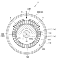
- FIG. 2 is a cross-sectional view taken along line II-II in FIG. 1 (Example 1).
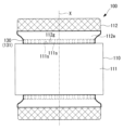
- 1 is a front view of an electric motor provided in a compressor according to an embodiment of the present disclosure (after a blocking unit has been attached).
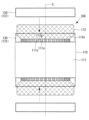
- FIG. 1 is a front view of an electric motor provided in a compressor according to an embodiment of the present disclosure (when a blocking unit is attached).
- FIG. FIG. 2 is a cross-sectional view taken along line II-II in FIG. 1 (Example 2).
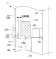
- FIG. 2 is a partially enlarged view of the vicinity of a coil end of the compressor shown in FIG. 1 (third embodiment);
- FIG. 2 is a cross-sectional view taken along line II-II in FIG. 1 (modification 1).
- the compressor 11 is, for example, a hermetic scroll compressor.
- the compressor 11 constitutes a refrigeration cycle together with a condenser, an expansion valve, an evaporator, refrigerant piping, and the like (not shown).
- the compressor 11 may be any compressor equipped with a scroll compression mechanism, and may be, for example, a compressor equipped with a compression mechanism that combines a scroll compression mechanism and a rotary compression mechanism (scroll-rotary compressor).
- the compressor 11 includes a housing 33 having an enclosed space therein, a discharge cover 40 that divides the enclosed space, a compression mechanism 60 that compresses the refrigerant R, a drive shaft 95 that causes the orbiting scroll 80 of the compression mechanism 60 to perform an orbital motion, an electric motor 100 that drives the drive shaft 95, and a shutoff unit 130.
- the housing 33 has an upper housing 33A, a middle housing 33B, and a lower housing (not shown) that form an enclosed space inside.
- the upper housing 33A and the intermediate housing 33B are connected with the outer peripheral end of the discharge cover 40 sandwiched therebetween. That is, the discharge cover 40 divides the sealed space inside the housing 33 in the direction of the axis X. Of the divided sealed spaces, the sealed space formed on the upper housing 33A side is a discharge chamber 53, and the sealed space formed on the middle housing 33B side is a suction chamber 55.
- a discharge pipe 31 for discharging the refrigerant R is provided on the top wall of the upper housing 33A, and connects the discharge chamber 53 to the outside of the upper housing 33A (housing 33).
- a refrigerant pipe is connected to the discharge pipe 31, and the refrigerant R discharged from the discharge pipe 31 is guided to a condenser.
- An intake port 33B1 is formed in the side wall of the intermediate housing 33B, and an intake pipe 32 for drawing in the refrigerant R is provided in the intake port 33B1, connecting the intake chamber 55 to the outside of the intermediate housing 33B (housing 33).
- a refrigerant pipe is connected to the suction pipe 32 so that the refrigerant R evaporated in the evaporator is guided to the suction chamber 55 .
- the suction chamber 55 is provided with a compression mechanism 60 that compresses the refrigerant R, a drive shaft 95 that transmits rotational force from the electric motor 100 to the compression mechanism 50, a support member 97 that supports the drive shaft 95, and the electric motor 100 that rotates the drive shaft 95.
- the compression mechanism 60 has a fixed scroll 70 having a spiral-shaped fixed side wall body 75 erected on a fixed side end plate 71, and a rotating scroll 80 having a spiral-shaped orbiting side wall body 85 erected on a orbiting side end plate 81.
- the fixed scroll 70 and the orbiting scroll 80 mesh with each other to form the compression chamber 61.
- tip gaps are set in consideration of the thermal expansion of each wall body.
- the fixed scroll 70 is fixed to the support member 97 by a fixing portion 74 formed on the outer circumferential end portion of the fixed side end plate 71. Since the support member 97 is fixed to the intermediate housing 33B, the fixed scroll 70 is fixed to the intermediate housing 33B via the support member 97. It should be noted that the terms “radial direction” and “circumferential direction” used herein are relative to the axis X of the fixed scroll 70.
- the orbiting scroll 80 is configured to revolve around the axis X of the fixed scroll 70 by means of a drive shaft 95 and an anti-rotation mechanism (e.g., an Oldham link).
- an anti-rotation mechanism e.g., an Oldham link
- a discharge cover 40 is disposed above the fixed scroll 70 (on the rear side of the fixed end plate 71), and together with the rear side of the fixed end plate 71 defines a back pressure chamber 54.
- a discharge port 72 is formed in the fixed end plate 71, which connects the compression chamber 61 and the back pressure chamber 54.
- a discharge port 41 (different from the discharge port 72 of the fixed end plate 71) is formed in the discharge cover 40, which connects the back pressure chamber 54 and the discharge chamber 53.
- the compression chamber 61 and the discharge chamber 53 are in communication with each other via the discharge port 72 , the back pressure chamber 54 and the discharge port 41 .
- the compressor 11 of this embodiment has a low-pressure housing structure in which the discharge cover 40 serves as a partition between the high-pressure side (discharge chamber 53) and the low-pressure side (suction chamber 55), and the drive shaft 95, support member 97, and electric motor 100 are disposed on the low-pressure side.
- the element separating the high-pressure side and the low-pressure side does not necessarily have to be the discharge cover 40, and the high-pressure side and the low-pressure side may be separated by, for example, the fixed scroll 70.
- a reed valve 92 and a retainer 93 that restricts the range of movement of the reed valve 92 are provided at the outlet of the discharge port 72.
- the electric motor 100 includes a stator 110 having distributed winding and fixed to an intermediate housing 33B, and a rotor 120 that is fixed to the drive shaft 95 and rotates about an axis X relative to the stator 110.
- the stator 110 includes a stator core 111 and a coil portion 112 .
- the stator core 111 is a laminate of thin electromagnetic steel sheets (laminated steel sheets) and is fixed to the intermediate housing 33B.
- the stator core 111 is formed with a plurality of slots 111s extending along the direction of the axis X.
- the plurality of slots 111s are provided at equal angular intervals in the circumferential direction.
- the coil portion 112 is formed of a linear conductor (e.g., an enameled wire) wound in the slot 111s.
- the coil portion 112 forms coil ends 112e that protrude along the axis X from both end faces of the stator core 111 in the axis X direction.
- the coil ends 112e are shown by cross-hatching in FIG. 1.
- a gap 112g is formed between the coil end 112e immediately after it protrudes from one slot 111s and the coil end 112e immediately after it protrudes from another slot 111s circumferentially adjacent to that slot 111s, and at a position adjacent to the end face of the stator core 111 in the direction of the axis X.
- the gaps 112g are formed at equal angular intervals in the circumferential direction, similar to the slots 111s, and the number of the gaps 112g corresponds to the number of the slots 111s.
- the gap 112g is a portion that is unique to the electric motor 100 (stator 110) with distributed winding, and does not generally exist in the electric motor 100 (stator 110) with concentrated winding.
- the rotor 120 is fixed to the outer circumferential surface of the drive shaft 95 .
- a counterweight 121 having a semicircular shape in the circumferential direction is attached to both end faces in the direction of the axis X of the rotor 120.
- the counterweight 121 rotates around the axis X together with the rotor 120.
- air can flow from the outer region (hereinafter also simply referred to as the "outer region") of the coil end 112e to the inner region (hereinafter also simply referred to as the “inner region”) in the suction chamber 55 through the gap 112g formed between one coil end 112e and the other coil end 112e.
- the coil end 112e of the stator 110 the upper coil end 112e in FIG.
- the refrigerant R may flow into the inner region of the coil end 112e.
- a counterweight 121 is present in the inner region, when refrigerant R enters the inner region, the refrigerant R containing mist-like oil is stirred by the counterweight 121, causing the oil to rise up and flow into the compression mechanism 60, which may increase the oil circulation rate.
- the compressor 11 is provided with a blocking section 130 that blocks the flow of the refrigerant R so that the refrigerant R does not flow from the outer region to the inner region through each gap 112g.
- a blocking section 130 that blocks the flow of the refrigerant R so that the refrigerant R does not flow from the outer region to the inner region through each gap 112g.
- the cutoff portion 130 (cutoff portion 131) of the first embodiment is an object that closes the gap 112g by closely contacting and covering the outer peripheral surface of the coil end 112e.
- the interrupter 131 is, for example, an annular band-shaped body having insulating properties and centered on the axis X.
- the band-shaped body is, for example, a resin film.
- This resin film is, for example, a heat shrinkable film that shrinks when heated.
- the heat shrink film serving as the cutoff portion 131 is, for example, an annular member having an inner diameter set larger than the maximum diameter portion of the coil end 112e.
- the heat shrink film is disposed at a height position overlapping with the gap 112g (shown by a two-dot chain line in FIG. 4), and then heated to shrink and come into close contact with the outer circumferential surface of the coil end 112e (see FIG. 3). As a result, the heat shrink film closes the gap 112g.
- the band-shaped body is not limited to a resin film, but may be a rubber band, a cord such as a binding cord, or one of these hardened with varnish.
- the blocking portion 130 (blocking portion 132) of the second embodiment is an object that fills all of the gaps 112g.
- the interrupter 132 has insulating properties.
- the blocking portions 132 filled in the gaps 112g may be independent of each other, or may be partially or entirely integrated. Also, after filling the gap 112g with the cutoff portion 132, the cutoff portion 131 may be provided on the outer circumferential surface of the coil end 112e.
- the cutoff portion 130 (cutoff portion 133) of the third embodiment is an annular baffle plate that is provided between the intermediate housing 33B and the outer peripheral surface of the coil end 112e in the radial direction and is not in contact with the coil end 112e and is centered on the axis X.
- the interrupter 133 has insulating properties.
- the baffle plate serving as the blocking portion 131 overlaps with the gap 112g in the height direction.
- the baffle plate may be attached to the stator core 111 or to the intermediate housing 33B. Also, the baffle plate may be attached to a portion other than these.
- the baffle plate is not in contact with the coil end 112e, but it is sufficient that the baffle plate is separated from the coil end 112e by a distance that allows electrical insulation (for example, 1.6 mm or more in the radial direction).
- the blocking portions 131, 133 are annular, or in the second embodiment, the blocking portion 132 fills all of the gaps 112g, thereby blocking the flow of the refrigerant R through all of the gaps 112g.
- the blocking portion 130 is arranged to block the flow of refrigerant R at least in the gap 112g in the range facing the suction port 33B1, in other words, in the gap 112g in the range overlapping with the suction port 33B1 in the circumferential direction.
- the cutoff portion 130 is provided in the above-described range, when the coil end 112e and the suction port 33B1 are disposed to face each other, the refrigerant R taken in from the suction port 33B1 collides with the cutoff portion 130. Then, as the refrigerant R collides with the cutoff portion 130, the oil in the refrigerant R is separated. Furthermore, by providing the cut-off portion 130 in the range described above, in the case where the coil end 112e and the suction port 33B1 are disposed to face each other, the refrigerant R taken in from the suction port 33B1 flows along the cut-off portion 130. As the refrigerant R flows along the cut-off portion 130, it has a velocity component in the circumferential direction, and the oil in the refrigerant R is centrifuged.
- the range in which the blocking section 130 is provided is, for example, ⁇ degrees in the circumferential direction from the position facing the center of the intake port 33B1.
- ⁇ is, for example, 60 degrees or more, and preferably 90 degrees or more.
- ⁇ Modification 2> For example, as shown in FIG. 1, it is preferable that the blocking portion 130 is inclined such that the outer circumferential surface approaches the axis X as it extends downward in a vertical cross section taken along the axis X. This makes it difficult for the refrigerant R containing the oil to rise up, and the oil circulation rate can be reduced.
- the cutoff portion 130 is provided in the upper coil end 112e.
- the cutoff portion 130 may be provided in the lower coil end 112e.
- the cutoff portion 130 may be disposed in the inner region of the coil end 112e.
- the blocking section 130 is configured to block the flow of low-pressure refrigerant R introduced through the suction port 33B1 connected to the suction pipe 32, but it may also be configured to block the flow of other refrigerants R.
- the blocking section 130 may be configured to block intermediate pressure gas, injection gas, and return gas from the capacity control mechanism.
- intermediate pressure gas refers to gas (refrigerant) compressed one or more times in a compression mechanism that compresses a refrigerant in multiple steps.
- injection gas refers to gas (refrigerant) that has been compressed and then released heat and then reheated.
- return gas from the capacity control mechanism refers to gas (refrigerant) that has entered the compression mechanism and is returned from the compression mechanism to the intermediate housing 33B before compression or immediately after the start of compression.
- the cutoff section 130 targets intermediate pressure gas and injection gas.
- the compressor 11 is provided with the blocking portion 130 (131, 132, 133), the amount of refrigerant R guided to the inner region of the coil end 112e can be reduced. It may be undesirable for the refrigerant R introduced into the outer region of the coil end 112e to flow into the inner region of the coil end 112e.
- the refrigerant R containing mist-like oil lubricating oil
- the counterweight 121 may be agitated by the counterweight 121, causing the oil to be stirred up and flow into the compression mechanism 60, which may increase the oil circulation rate.
- the blocking portion 131 is an object that closes the gap 112g by closely contacting and covering the outer peripheral surface of the coil end 112e, so it can reliably block the flow of the refrigerant R with a simple structure.
- the blocking portion 132 is an object that fills the gap 112g, so it can reliably block the flow of refrigerant R with a simple structure.
- the blocking portion 133 is a baffle plate, it can block the flow of refrigerant with a simple structure. Also, the blocking portion 133 can be easily installed.
- the blocking portion 130 at least in the area facing the suction port 33B1, the flow of the refrigerant R from the outer region toward the inner region of the coil end 112e through the gap 112g can be efficiently blocked.
- the refrigerant R taken in from the suction port 33B1 collides with the blocking portion 130 the oil in the refrigerant R is separated, and the oil circulation rate can be reduced.
- the refrigerant R taken in from the suction port 33B1 flows along the blocking portion 130, and thus has a velocity component in the circumferential direction, and the oil in the refrigerant R is centrifuged, thereby reducing the oil circulation rate.
- the blocking section 130 is inclined so that it approaches the axis X as it moves downward in a vertical cross section along the axis X, the refrigerant R containing oil is less likely to be rolled up, and the oil circulation rate can be reduced.
- a compressor (11) according to a first aspect of the present disclosure includes a housing (33) into which a refrigerant (R) is guided, a compression mechanism (60) accommodated in the housing and compressing the refrigerant, and an electric motor (100) accommodated in the housing and rotatably driving the compression mechanism via a drive shaft (95) extending along an axis (X).
- the electric motor has a stator core (111) in which a plurality of slots (111s) are provided in the circumferential direction and a coil portion (112) provided in each of the slots, and is a distributed winding in which a gap is formed between each coil end (112e) of the coil portion protruding from each slot of the stator core in the axial direction, and includes a blocking portion (130) that blocks the flow of refrigerant from an outer region in the radial direction of the coil end toward an inner region through the gap.
- the electric motor has distributed winding with gaps formed between each coil end, and the compressor has a blocking portion that blocks the flow of refrigerant from the radially outer region of the coil end to the radially inner region through the gap, thereby reducing the amount of refrigerant guided to the region on the inner side of the coil end. It may be undesirable for the refrigerant introduced into the area outside the coil end to flow into the area inside the coil end.
- the refrigerant containing mist-like oil may be stirred by the counterweight, causing the oil to rise and flow into the compression mechanism, increasing the oil circulation rate. Therefore, by reducing the amount of refrigerant guided to the area inside the coil end by the blocking section, the amount of oil flowing into the compression mechanism due to winding can be reduced, thereby suppressing the phenomenon of an increase in the oil circulation rate.
- the blocking portion (131) is an object that seals the gap by closely contacting and covering the outer peripheral surface of the coil end.
- the blocking portion is an object that seals the gap by closely contacting and covering the outer peripheral surface of the coil end, so the flow of refrigerant can be blocked reliably with a simple structure.
- the blocking portion (132) is an object that fills the gap.
- the blocking portion is an object that fills the gap, so the flow of refrigerant can be blocked reliably with a simple structure.
- the blocking portion (133) is a baffle plate that is provided between the housing and the coil end in the radial direction and is not in contact with the coil end.
- the blocking portion is disposed between the housing and the coil end in the radial direction, and is a baffle plate that is not in contact with the coil end, so the flow of refrigerant can be blocked with a simple structure.
- the blocking portion can be easily installed.
- the compressor according to the fifth aspect of the present disclosure is any one of the first to fourth aspects, in which the blocking portion is provided at least in an area facing an intake port (33B1) that is provided in the housing and takes in refrigerant into the housing.
- the blocking portion is provided at least in the area opposite the suction port, so that the flow of refrigerant from the outer region of the coil end to the inner region through the gap can be efficiently blocked.
- the refrigerant taken in from the suction port collides with the blocking portion, the oil in the refrigerant is separated, and the oil circulation rate can be reduced.
- the refrigerant taken in from the suction port flows along the blocking portion, which has a velocity component in the circumferential direction, and the oil in the refrigerant is centrifuged, thereby reducing the oil circulation rate.
- the compressor according to the sixth aspect of the present disclosure is the fifth aspect, in which the cutoff portion provided at a position corresponding to the upper coil end among the coil ends above and below the stator core is inclined so as to approach the axis as it goes downward in a vertical cross section along the axis.
- the cutoff section is inclined so that it approaches the axis as it moves downward in a longitudinal section along the axis, so that the refrigerant containing oil is less likely to be rolled up, and the oil circulation rate can be reduced.
- Compressor 31 Discharge pipe 32 Suction pipe 33 Housing 33A Upper housing (housing) 33B Intermediate housing (housing) 33B1 Intake port 40 Discharge cover 41 Discharge port 53 Discharge chamber 54 Back pressure chamber 55 Suction chamber 60 Compression mechanism 61 Compression chamber 70 Fixed scroll 71 Fixed side end plate 72 Discharge port 74 Fixed portion 75 Fixed side wall body 80 Orbiting scroll 81 Orbiting side end plate 85 Orbiting side wall body 92 Reed valve 93 Retainer 95 Drive shaft 97 Support member 100 Electric motor 110 Stator 111 Stator core 111s Slot 112 Coil portion 112e Coil end 112g Gap (circumferential gap) 120 rotor 121 counterweight 130 (131, 132, 133) cutoff section
Landscapes
- Engineering & Computer Science (AREA)
- Mechanical Engineering (AREA)
- General Engineering & Computer Science (AREA)
- Compressor (AREA)
- Applications Or Details Of Rotary Compressors (AREA)
Abstract
Description
このような密閉型圧縮機においては、例えば特許文献1に開示されているように、オイル循環率を低減することが望まれる場合がある。
本開示の一態様に係る圧縮機は、内部に冷媒が導かれるハウジングと、前記ハウジングに収容され、冷媒を圧縮する圧縮機構と、前記ハウジングに収容され、軸線に沿って延びた駆動軸を介して前記圧縮機構を回転駆動する電動モータと、を備え、前記電動モータは、複数のスロットが円周方向に設けられたステータコア及び各前記スロットに設けられたコイル部を有し、かつ、前記ステータコアの各前記スロットから前記軸線の方向に突出した前記コイル部の各コイルエンド間に隙間が形成された分布巻きとされ、前記隙間を介して前記コイルエンドの半径方向の外側の領域から内側の領域に向かう冷媒の流れを遮る遮断部を備えている。
圧縮機11は、例えば密閉型のスクロール圧縮機である。
圧縮機11は、図示しない凝縮器、膨張弁、蒸発器、冷媒配管等と共に冷凍サイクルを構成する。
なお、圧縮機11は、スクロール圧縮機構を備えた圧縮機であればよく、例えばスクロール圧縮機構とロータリー圧縮機構とを組み合わせた圧縮機構を備えた圧縮機(スクロータリー圧縮機)であってもよい。
すなわち、ディスチャージカバー40によってハウジング33の内部の密閉空間が軸線Xの方向に分割されている。分割された密閉空間のうち、上部ハウジング33A側に形成された密閉空間が吐出チャンバ53とされ、中間ハウジング33B側に形成された密閉空間が吸入室55とされている。
吐出管31には冷媒配管が接続されており、吐出管31から吐出した冷媒Rが凝縮器に導かれるように構成されている。
吸入管32には冷媒配管が接続されており、蒸発器で蒸発した冷媒Rが吸入室55に導かれるように構成されている。
固定スクロール70及び旋回スクロール80においては、固定側壁体75と旋回側壁体85とが互いに噛み合って圧縮室61を形成している。固定側壁体75の歯先と旋回側端板81の歯底との間、及び、旋回側壁体85の歯先と固定側端板71の歯底との間には、各壁体の熱膨張を考慮したチップ隙間が設定されている。
なお、ここでいう「半径方向」や「円周方向」とは、固定スクロール70の軸線Xに対するものである。
つまり、圧縮室61と吐出チャンバ53とは、吐出ポート72、背圧室54及び吐出ポート41を介して連通している。
したがって、本実施形態の圧縮機11は、ディスチャージカバー40を高圧側(吐出チャンバ53)と低圧側(吸入室55)との仕切りとし、低圧側に駆動軸95、サポート部材97や電動モータ100が配置された低圧ハウジング構造となっている。なお、高圧側と低圧側とを仕切り要素は必ずしもディスチャージカバー40である必要はなく、例えば固定スクロール70によって仕切られていてもよい。
図1から図3に示すように、電動モータ100は、分布巻きとされ、中間ハウジング33Bに固定されたステータ110と、駆動軸95に固定されるとともにステータ110に対して軸線X回りに回転するロータ120と、を備えている。
ステータコア111は、薄い電磁鋼板の積層体(積層鋼板)であり、中間ハウジング33Bに固定されている。ステータコア111には、軸線Xの方向に沿って延びる複数のスロット111sが形成されている。複数のスロット111sは、円周方向において等角度間隔で設けられている。
コイル部112は、スロット111sに巻回された線状の導体(例えばエナメル線)によって形成されている。コイル部112は、ステータコア111の軸線Xの方向における両端面から軸線Xの方向に沿って突出したコイルエンド112eを形成している。説明のために、図1ではコイルエンド112eをクロスハッチングで表示している。
隙間112gは、スロット111sと同様に円周方向において等角度間隔で形成され、かつ、スロット111sの数に対応した数だけ形成されている。
隙間112gは、分布巻きの電動モータ100(ステータ110)に特有の部分であり、一般的には集中巻きの電動モータ100(ステータ110)には存在しない。
ロータ120の軸線Xの方向における両端面には、円周方向において半円弧状のカウンターウェイト121が取り付けられている。このカウンターウェイト121は、ロータ120と共に軸線Xの周りに回転する。
特に、ステータ110のコイルエンド112e(図1では上側のコイルエンド112e)が中間ハウジング33Bの側壁に設けられた吸入口33B1と対向するように配置されている場合、言い換えれば、上側のコイルエンド112eと吸入口33B1とが、軸線Xの方向(高さ方向)において重複した範囲にある場合、吸入口33B1から取り込まれた冷媒Rが隙間112gを介して直接的に外側領域から内側領域に流れ込みやすくなる。
例えば、内側領域にカウンターウェイト121が存在している場合、内側領域に冷媒Rが入り込むと、ミスト状のオイルを含む冷媒Rがカウンターウェイト121によって撹拌され、オイルが巻き上がり、圧縮機構60に流れ込み、オイル循環率が上昇する可能性がある。
以下、遮断部130について、実施例1から実施例3及び変形例1から変形例3を例に説明する。
図1から図3に示すように、実施例1の遮断部130(遮断部131)は、コイルエンド112eの外周面に密着しつつその外周面を覆うことで隙間112gを塞ぐ物体とされている。
遮断部131は、例えば、絶縁性を有する軸線Xを中心とした環状の帯状体とされている。
この樹脂製のフィルムは、例えば、加熱によって収縮する熱収縮フィルムとされる。
図4に示すように、遮断部131としての熱収縮フィルムは、例えば、コイルエンド112eの最大径部よりも大きな内径が設定された環状部材とされている。
熱収縮フィルムは、隙間112gと重複する高さ位置に配置された後(図4において二点鎖線で表示)、加熱することで収縮してコイルエンド112eの外周面に密着する(図3参照)。これによって、熱収縮フィルムが隙間112gを塞ぐことになる。
図5に示すように、実施例2の遮断部130(遮断部132)は、全ての隙間112gを埋める物体とされている。
遮断部132は、絶縁性を有している。
また、隙間112gを遮断部132で埋めた上で、コイルエンド112eの外周面に遮断部131を設けてもよい。
図6に示すように、実施例3の遮断部130(遮断部133)は、半径方向において中間ハウジング33Bとコイルエンド112eの外周面との間に設けられ、かつ、コイルエンド112eと接触していない、軸線Xを中心とした環状の邪魔板とされている。
遮断部133は、絶縁性を有している。
邪魔板は、ステータコア111に取り付けられてもよいし、中間ハウジング33Bに取り付けられてもよい。また、邪魔板をそれら以外の部位に取り付けてもよい。
邪魔板は、コイルエンド112eと非接触とされているが、少なくとも電気的に絶縁可能な距離だけ離れていれば十分である(例えば、半径方向に1.6mm以上)。
実施例1及び実施例3においては遮断部131,133を環状とすることで、或いは、実施例2においては遮断部132で全ての隙間112gを埋めることで、全ての隙間112gにおける冷媒Rの流通を遮っていた。
しかしながら、遮断部130は、少なくとも、吸入口33B1と対向する範囲にある隙間112g、言い換えれば、円周方向において吸入口33B1と重複した範囲にある隙間112gにおける冷媒Rの流通を遮るように設けられていればよい。
また、上記のような範囲に遮断部130を設けておけば、コイルエンド112eと吸入口33B1とが対向するように配置されている場合において、吸入口33B1から取り込まれた冷媒Rが遮断部130に沿って流れるようになる。そして、冷媒Rが遮断部130に沿って流れることで円周方向に速度成分を持ち、冷媒R中のオイルが遠心分離される。
また、コイルエンド112eの内側領域に流れ込む冷媒Rの量を低減するという意味においては、吸入口33B1と対向した範囲にある隙間112gに遮断部130を設けずとも、円周方向において吸入口33B1と対向していない範囲にある隙間112gに遮断部130を設けておけば、少なくともその効果を発揮する。
例えば図1に示すように、遮断部130は、軸線Xに沿った縦断面において外周面が下方に向かうにつれて軸線Xに近付くように傾斜していることが好ましい。
これによって、オイルを含む冷媒Rが巻き上がりにくくなり、オイル循環率を低下させることができる。
以上の実施例(変形例を含む)では、上側のコイルエンド112eに遮断部130を設けていたが、その遮断部130に加えて/代えて、下側のコイルエンド112eに遮断部130を設けてもよい。
また、遮断部130をコイルエンド112eの内側領域に配置してもよい。
以上の実施例(変形例を含む)では、遮断部130は、吸入管32と接続された吸入口33B1を介して導かれた低圧の冷媒Rの流通を遮るように構成されていたが、それ以外の冷媒Rの流通を遮るように構成されてもよい。
例えば、中間圧のガス、インジェクションガスや容量制御機構からの戻りガスを遮るように遮断部130を構成してもよい。
ここで、「中間圧のガス」とは、複数回に分けて冷媒を圧縮する圧縮機構において、1回以上圧縮されたガス(冷媒)のことである。また、「インジェクションガス」とは、圧縮後のガス(冷媒)を一度放熱し、再加熱したガスのことである。また、「容量制御機構からの戻りガス」とは、圧縮機構に入ったガス(冷媒)のうち、圧縮される前又は圧縮開始直後に圧縮機構から中間ハウジング33Bに戻されたガスのことである。
圧縮機11が、スクロータリー圧縮機の場合、遮断部130は、中間圧のガスやインジェクションガスを対象とすることになる。
圧縮機11は、遮断部130(131,132,133)を備えているので、コイルエンド112eの内側領域に導かれる冷媒Rの量を低減することができる。
コイルエンド112eの外側領域に導かれた冷媒Rがコイルエンド112eの内側領域に流れ込むと好ましくない場合がある。例えば、コイルエンド112eの内側領域に、ロータ120に取り付けられたカウンターウェイト121が存在している場合、その領域に冷媒Rが入り込むと、ミスト状のオイル(潤滑油)を含む冷媒Rがカウンターウェイト121によって撹拌され、オイルが巻き上がり、圧縮機構60に流れ込み、オイル循環率が上昇する可能性がある。
そこで、遮断部130によってコイルエンド112eの内側領域に導かれる冷媒Rの量を低減することで、巻き上がりによって圧縮機構60に流れ込むオイルの量を低減して、オイル循環率が上昇する現象を抑制することができる。
また、吸入口33B1から取り込まれた冷媒Rが遮断部130に衝突することで冷媒R中のオイルが分離され、オイル循環率を低下させることができる。
また、吸入口33B1から取り込まれた冷媒Rが遮断部130に沿って流れることで円周方向に速度成分を持ち、冷媒R中のオイルが遠心分離され、オイル循環率を低下させることができる。
本開示の第1態様に係る圧縮機(11)は、内部に冷媒(R)が導かれるハウジング(33)と、前記ハウジングに収容され、冷媒を圧縮する圧縮機構(60)と、前記ハウジングに収容され、軸線(X)に沿って延びた駆動軸(95)を介して前記圧縮機構を回転駆動する電動モータ(100)と、を備え、前記電動モータは、複数のスロット(111s)が円周方向に設けられたステータコア(111)及び各前記スロットに設けられたコイル部(112)を有し、かつ、前記ステータコアの各前記スロットから前記軸線の方向に突出した前記コイル部の各コイルエンド(112e)間に隙間が形成された分布巻きとされ、前記隙間を介して前記コイルエンドの半径方向の外側の領域から内側の領域に向かう冷媒の流れを遮る遮断部(130)を備えている。
コイルエンドの外側にある領域に導かれた冷媒がコイルエンドの内側にある領域に流れ込むと好ましくない場合がある。例えば、コイルエンドの内側にある領域に、ロータに取り付けられたカウンターウェイトが存在している場合、その領域に冷媒が入り込むと、ミスト状のオイル(潤滑油)を含む冷媒がカウンターウェイトによって撹拌され、オイルが巻き上がり、圧縮機構に流れ込み、オイル循環率が上昇する可能性がある。
そこで、遮断部によってコイルエンドの内側にある領域に導かれる冷媒の量を低減することで、巻き上がりによって圧縮機構に流れ込むオイルの量を低減して、オイル循環率が上昇する現象を抑制することができる。
また、吸入口から取り込まれた冷媒が遮断部に衝突することで冷媒中のオイルが分離され、オイル循環率を低下させることができる。
また、吸入口から取り込まれた冷媒が遮断部に沿って流れることで円周方向に速度成分を持ち、冷媒中のオイルが遠心分離され、オイル循環率を低下させることができる。
31 吐出管
32 吸入管
33 ハウジング
33A 上部ハウジング(ハウジング)
33B 中間ハウジング(ハウジング)
33B1 吸入口
40 ディスチャージカバー
41 吐出ポート
53 吐出チャンバ
54 背圧室
55 吸入室
60 圧縮機構
61 圧縮室
70 固定スクロール
71 固定側端板
72 吐出ポート
74 固定部
75 固定側壁体
80 旋回スクロール
81 旋回側端板
85 旋回側壁体
92 リード弁
93 リテーナ
95 駆動軸
97 サポート部材
100 電動モータ
110 ステータ
111 ステータコア
111s スロット
112 コイル部
112e コイルエンド
112g 隙間(円周方向の隙間)
120 ロータ
121 カウンターウェイト
130(131,132,133) 遮断部
Claims (6)
- 内部に冷媒が導かれるハウジングと、
前記ハウジングに収容され、冷媒を圧縮する圧縮機構と、
前記ハウジングに収容され、軸線に沿って延びた駆動軸を介して前記圧縮機構を回転駆動する電動モータと、
を備え、
前記電動モータは、複数のスロットが円周方向に設けられたステータコア及び各前記スロットに設けられたコイル部を有し、かつ、前記ステータコアの各前記スロットから前記軸線の方向に突出した前記コイル部の各コイルエンド間に隙間が形成された分布巻きとされ、
前記隙間を介して前記コイルエンドの半径方向の外側の領域から内側の領域に向かう冷媒の流れを遮る遮断部を備えている
圧縮機。 - 前記遮断部は、前記コイルエンドの外周面に密着しつつその外周面を覆うことで前記隙間を塞ぐ物体とされている
請求項1に記載の圧縮機。 - 前記遮断部は、前記隙間を埋める物体とされている
請求項1に記載の圧縮機。 - 前記遮断部は、前記半径方向において前記ハウジングと前記コイルエンドとの間に設けられ、かつ、前記コイルエンドと接触していない邪魔板とされている
請求項1に記載の圧縮機。 - 前記遮断部は、少なくとも、前記ハウジングに設けられ前記ハウジングの内部に冷媒を取り込む吸入口と対向した範囲に設けられている
請求項1から4のいずれかに記載の圧縮機。 - 前記ステータコアの上方及び下方にある前記コイルエンドのうち上方にある前記コイルエンドに対応する位置に設けられた前記遮断部は、前記軸線に沿った縦断面において下方に向かうにつれて前記軸線に近付くように傾斜している
請求項5に記載の圧縮機。
Priority Applications (1)
| Application Number | Priority Date | Filing Date | Title |
|---|---|---|---|
| EP24770462.0A EP4678916A4 (en) | 2023-03-16 | 2024-02-21 | COMPRESSOR |
Applications Claiming Priority (2)
| Application Number | Priority Date | Filing Date | Title |
|---|---|---|---|
| JP2023-042167 | 2023-03-16 | ||
| JP2023042167A JP2024131733A (ja) | 2023-03-16 | 2023-03-16 | 圧縮機 |
Publications (1)
| Publication Number | Publication Date |
|---|---|
| WO2024190349A1 true WO2024190349A1 (ja) | 2024-09-19 |
Family
ID=92754947
Family Applications (1)
| Application Number | Title | Priority Date | Filing Date |
|---|---|---|---|
| PCT/JP2024/006399 Ceased WO2024190349A1 (ja) | 2023-03-16 | 2024-02-21 | 圧縮機 |
Country Status (3)
| Country | Link |
|---|---|
| EP (1) | EP4678916A4 (ja) |
| JP (1) | JP2024131733A (ja) |
| WO (1) | WO2024190349A1 (ja) |
Citations (3)
| Publication number | Priority date | Publication date | Assignee | Title |
|---|---|---|---|---|
| JP2007100512A (ja) | 2005-09-30 | 2007-04-19 | Mitsubishi Heavy Ind Ltd | 密閉型回転式圧縮機 |
| JP2009191761A (ja) * | 2008-02-15 | 2009-08-27 | Denso Corp | 密閉型電動圧縮機 |
| JP2013060822A (ja) * | 2011-09-12 | 2013-04-04 | Toyota Industries Corp | 電動圧縮機 |
Family Cites Families (3)
| Publication number | Priority date | Publication date | Assignee | Title |
|---|---|---|---|---|
| JP4492043B2 (ja) * | 2003-06-09 | 2010-06-30 | ダイキン工業株式会社 | 圧縮機 |
| WO2010150542A1 (ja) * | 2009-06-23 | 2010-12-29 | ダイキン工業株式会社 | 圧縮機 |
| JP6596222B2 (ja) * | 2015-04-14 | 2019-10-23 | 日立ジョンソンコントロールズ空調株式会社 | 密閉型電動圧縮機 |
-
2023
- 2023-03-16 JP JP2023042167A patent/JP2024131733A/ja active Pending
-
2024
- 2024-02-21 EP EP24770462.0A patent/EP4678916A4/en active Pending
- 2024-02-21 WO PCT/JP2024/006399 patent/WO2024190349A1/ja not_active Ceased
Patent Citations (3)
| Publication number | Priority date | Publication date | Assignee | Title |
|---|---|---|---|---|
| JP2007100512A (ja) | 2005-09-30 | 2007-04-19 | Mitsubishi Heavy Ind Ltd | 密閉型回転式圧縮機 |
| JP2009191761A (ja) * | 2008-02-15 | 2009-08-27 | Denso Corp | 密閉型電動圧縮機 |
| JP2013060822A (ja) * | 2011-09-12 | 2013-04-04 | Toyota Industries Corp | 電動圧縮機 |
Non-Patent Citations (1)
| Title |
|---|
| See also references of EP4678916A1 |
Also Published As
| Publication number | Publication date |
|---|---|
| EP4678916A4 (en) | 2026-04-15 |
| EP4678916A1 (en) | 2026-01-14 |
| JP2024131733A (ja) | 2024-09-30 |
Similar Documents
| Publication | Publication Date | Title |
|---|---|---|
| EP2129917B1 (en) | Compressor and oil separation device therefor | |
| EP2107667B1 (en) | Motor and compressor | |
| US6106251A (en) | Scroll machine with reverse rotation sound attenuation | |
| EP2113053A1 (en) | Compressor and oil separating device therefor | |
| CN114439746A (zh) | 涡旋式压缩机 | |
| JP2004270668A (ja) | 密閉型圧縮機 | |
| CN101936292B (zh) | 压缩机 | |
| EP3567213B1 (en) | Scroll compressor | |
| CN101900114A (zh) | 压缩机 | |
| JP2024131733A (ja) | 圧縮機 | |
| US20060257272A1 (en) | Compressor | |
| JP3389682B2 (ja) | 密閉型スクロール圧縮機 | |
| CN217421523U (zh) | 涡旋式压缩机以及包括其的空调机 | |
| JP3124437B2 (ja) | スクロール圧縮機 | |
| KR20050061275A (ko) | 전동 압축기 | |
| CN218581816U (zh) | 压缩机 | |
| US11668301B2 (en) | Scroll compressor having a press-fitted motor and a vertically central suction inlet | |
| JP7534659B2 (ja) | スクロール圧縮機、及び、冷媒サイクル装置 | |
| EP4273401B1 (en) | Scroll compressor | |
| JP7598080B1 (ja) | 圧縮機及び冷凍装置 | |
| JP2008148526A (ja) | モータ用のステータ、モータおよび圧縮機 | |
| JP2012202214A (ja) | 圧縮機 | |
| JP2703521B2 (ja) | 密閉形スクロール流体装置 | |
| JP2024127087A (ja) | 電動圧縮機 | |
| KR20240129887A (ko) | 밀폐형 압축기 |
Legal Events
| Date | Code | Title | Description |
|---|---|---|---|
| 121 | Ep: the epo has been informed by wipo that ep was designated in this application |
Ref document number: 24770462 Country of ref document: EP Kind code of ref document: A1 |
|
| WWE | Wipo information: entry into national phase |
Ref document number: 2024770462 Country of ref document: EP |
|
| NENP | Non-entry into the national phase |
Ref country code: DE |
|
| ENP | Entry into the national phase |
Ref document number: 2024770462 Country of ref document: EP Effective date: 20251009 |
|
| ENP | Entry into the national phase |
Ref document number: 2024770462 Country of ref document: EP Effective date: 20251009 |
|
| ENP | Entry into the national phase |
Ref document number: 2024770462 Country of ref document: EP Effective date: 20251009 |
|
| ENP | Entry into the national phase |
Ref document number: 2024770462 Country of ref document: EP Effective date: 20251009 |
|
| WWP | Wipo information: published in national office |
Ref document number: 2024770462 Country of ref document: EP |