WO2024190895A1 - フィルターユニット、精製装置及び精製液の製造方法 - Google Patents
フィルターユニット、精製装置及び精製液の製造方法 Download PDFInfo
- Publication number
- WO2024190895A1 WO2024190895A1 PCT/JP2024/010177 JP2024010177W WO2024190895A1 WO 2024190895 A1 WO2024190895 A1 WO 2024190895A1 JP 2024010177 W JP2024010177 W JP 2024010177W WO 2024190895 A1 WO2024190895 A1 WO 2024190895A1
- Authority
- WO
- WIPO (PCT)
- Prior art keywords
- filter
- functional layer
- separation functional
- filter unit
- housing
- Prior art date
- Legal status (The legal status is an assumption and is not a legal conclusion. Google has not performed a legal analysis and makes no representation as to the accuracy of the status listed.)
- Ceased
Links
Classifications
-
- B—PERFORMING OPERATIONS; TRANSPORTING
- B01—PHYSICAL OR CHEMICAL PROCESSES OR APPARATUS IN GENERAL
- B01D—SEPARATION
- B01D61/00—Processes of separation using semi-permeable membranes, e.g. dialysis, osmosis or ultrafiltration; Apparatus, accessories or auxiliary operations specially adapted therefor
- B01D61/14—Ultrafiltration; Microfiltration
- B01D61/145—Ultrafiltration
-
- B—PERFORMING OPERATIONS; TRANSPORTING
- B01—PHYSICAL OR CHEMICAL PROCESSES OR APPARATUS IN GENERAL
- B01D—SEPARATION
- B01D29/00—Filters with filtering elements stationary during filtration, e.g. pressure or suction filters, not covered by groups B01D24/00 - B01D27/00; Filtering elements therefor
- B01D29/50—Filters with filtering elements stationary during filtration, e.g. pressure or suction filters, not covered by groups B01D24/00 - B01D27/00; Filtering elements therefor with multiple filtering elements, characterised by their mutual disposition
-
- B—PERFORMING OPERATIONS; TRANSPORTING
- B01—PHYSICAL OR CHEMICAL PROCESSES OR APPARATUS IN GENERAL
- B01D—SEPARATION
- B01D39/00—Filtering material for liquid or gaseous fluids
- B01D39/14—Other self-supporting filtering material ; Other filtering material
- B01D39/16—Other self-supporting filtering material ; Other filtering material of organic material, e.g. synthetic fibres
- B01D39/1607—Other self-supporting filtering material ; Other filtering material of organic material, e.g. synthetic fibres the material being fibrous
- B01D39/1623—Other self-supporting filtering material ; Other filtering material of organic material, e.g. synthetic fibres the material being fibrous of synthetic origin
-
- B—PERFORMING OPERATIONS; TRANSPORTING
- B01—PHYSICAL OR CHEMICAL PROCESSES OR APPARATUS IN GENERAL
- B01D—SEPARATION
- B01D61/00—Processes of separation using semi-permeable membranes, e.g. dialysis, osmosis or ultrafiltration; Apparatus, accessories or auxiliary operations specially adapted therefor
- B01D61/14—Ultrafiltration; Microfiltration
- B01D61/18—Apparatus therefor
-
- B—PERFORMING OPERATIONS; TRANSPORTING
- B01—PHYSICAL OR CHEMICAL PROCESSES OR APPARATUS IN GENERAL
- B01D—SEPARATION
- B01D63/00—Apparatus in general for separation processes using semi-permeable membranes
- B01D63/02—Hollow fibre modules
-
- B—PERFORMING OPERATIONS; TRANSPORTING
- B01—PHYSICAL OR CHEMICAL PROCESSES OR APPARATUS IN GENERAL
- B01D—SEPARATION
- B01D69/00—Semi-permeable membranes for separation processes or apparatus characterised by their form, structure or properties; Manufacturing processes specially adapted therefor
- B01D69/02—Semi-permeable membranes for separation processes or apparatus characterised by their form, structure or properties; Manufacturing processes specially adapted therefor characterised by their properties
-
- B—PERFORMING OPERATIONS; TRANSPORTING
- B01—PHYSICAL OR CHEMICAL PROCESSES OR APPARATUS IN GENERAL
- B01D—SEPARATION
- B01D69/00—Semi-permeable membranes for separation processes or apparatus characterised by their form, structure or properties; Manufacturing processes specially adapted therefor
- B01D69/08—Hollow fibre membranes
-
- B—PERFORMING OPERATIONS; TRANSPORTING
- B01—PHYSICAL OR CHEMICAL PROCESSES OR APPARATUS IN GENERAL
- B01D—SEPARATION
- B01D71/00—Semi-permeable membranes for separation processes or apparatus characterised by the material; Manufacturing processes specially adapted therefor
- B01D71/06—Organic material
- B01D71/28—Polymers of vinyl aromatic compounds
-
- B—PERFORMING OPERATIONS; TRANSPORTING
- B01—PHYSICAL OR CHEMICAL PROCESSES OR APPARATUS IN GENERAL
- B01D—SEPARATION
- B01D71/00—Semi-permeable membranes for separation processes or apparatus characterised by the material; Manufacturing processes specially adapted therefor
- B01D71/06—Organic material
- B01D71/44—Polymers obtained by reactions only involving carbon-to-carbon unsaturated bonds, not provided for in a single one of groups B01D71/26-B01D71/42
-
- B—PERFORMING OPERATIONS; TRANSPORTING
- B01—PHYSICAL OR CHEMICAL PROCESSES OR APPARATUS IN GENERAL
- B01D—SEPARATION
- B01D71/00—Semi-permeable membranes for separation processes or apparatus characterised by the material; Manufacturing processes specially adapted therefor
- B01D71/06—Organic material
- B01D71/56—Polyamides, e.g. polyester-amides
-
- B—PERFORMING OPERATIONS; TRANSPORTING
- B01—PHYSICAL OR CHEMICAL PROCESSES OR APPARATUS IN GENERAL
- B01D—SEPARATION
- B01D71/00—Semi-permeable membranes for separation processes or apparatus characterised by the material; Manufacturing processes specially adapted therefor
- B01D71/06—Organic material
- B01D71/66—Polymers having sulfur in the main chain, with or without nitrogen, oxygen or carbon only
- B01D71/68—Polysulfones; Polyethersulfones
-
- B—PERFORMING OPERATIONS; TRANSPORTING
- B01—PHYSICAL OR CHEMICAL PROCESSES OR APPARATUS IN GENERAL
- B01D—SEPARATION
- B01D2239/00—Aspects relating to filtering material for liquid or gaseous fluids
- B01D2239/06—Filter cloth, e.g. knitted, woven non-woven; self-supported material
- B01D2239/0604—Arrangement of the fibres in the filtering material
- B01D2239/0618—Non-woven
-
- B—PERFORMING OPERATIONS; TRANSPORTING
- B01—PHYSICAL OR CHEMICAL PROCESSES OR APPARATUS IN GENERAL
- B01D—SEPARATION
- B01D2239/00—Aspects relating to filtering material for liquid or gaseous fluids
- B01D2239/06—Filter cloth, e.g. knitted, woven non-woven; self-supported material
- B01D2239/0604—Arrangement of the fibres in the filtering material
- B01D2239/0622—Melt-blown
-
- B—PERFORMING OPERATIONS; TRANSPORTING
- B01—PHYSICAL OR CHEMICAL PROCESSES OR APPARATUS IN GENERAL
- B01D—SEPARATION
- B01D2239/00—Aspects relating to filtering material for liquid or gaseous fluids
- B01D2239/06—Filter cloth, e.g. knitted, woven non-woven; self-supported material
- B01D2239/065—More than one layer present in the filtering material
- B01D2239/0654—Support layers
-
- B—PERFORMING OPERATIONS; TRANSPORTING
- B01—PHYSICAL OR CHEMICAL PROCESSES OR APPARATUS IN GENERAL
- B01D—SEPARATION
- B01D2239/00—Aspects relating to filtering material for liquid or gaseous fluids
- B01D2239/06—Filter cloth, e.g. knitted, woven non-woven; self-supported material
- B01D2239/065—More than one layer present in the filtering material
- B01D2239/0672—The layers being joined by welding
-
- B—PERFORMING OPERATIONS; TRANSPORTING
- B01—PHYSICAL OR CHEMICAL PROCESSES OR APPARATUS IN GENERAL
- B01D—SEPARATION
- B01D2239/00—Aspects relating to filtering material for liquid or gaseous fluids
- B01D2239/12—Special parameters characterising the filtering material
- B01D2239/1208—Porosity
-
- B—PERFORMING OPERATIONS; TRANSPORTING
- B01—PHYSICAL OR CHEMICAL PROCESSES OR APPARATUS IN GENERAL
- B01D—SEPARATION
- B01D2239/00—Aspects relating to filtering material for liquid or gaseous fluids
- B01D2239/12—Special parameters characterising the filtering material
- B01D2239/1216—Pore size
-
- B—PERFORMING OPERATIONS; TRANSPORTING
- B01—PHYSICAL OR CHEMICAL PROCESSES OR APPARATUS IN GENERAL
- B01D—SEPARATION
- B01D2239/00—Aspects relating to filtering material for liquid or gaseous fluids
- B01D2239/12—Special parameters characterising the filtering material
- B01D2239/1233—Fibre diameter
-
- B—PERFORMING OPERATIONS; TRANSPORTING
- B01—PHYSICAL OR CHEMICAL PROCESSES OR APPARATUS IN GENERAL
- B01D—SEPARATION
- B01D2325/00—Details relating to properties of membranes
- B01D2325/02—Details relating to pores or porosity of the membranes
- B01D2325/0283—Pore size
-
- B—PERFORMING OPERATIONS; TRANSPORTING
- B01—PHYSICAL OR CHEMICAL PROCESSES OR APPARATUS IN GENERAL
- B01D—SEPARATION
- B01D2325/00—Details relating to properties of membranes
- B01D2325/04—Characteristic thickness
Definitions
- the present invention relates to a filter unit, a purification device, and a method for producing a purified liquid.
- Patent Document 1 discloses a method for purifying a viral vector by stepwise using filters with pores of a size that allows the viral vector to pass through but not cells and other cell culture components (impurities).
- Patent Document 1 discloses a method for purifying cell fragments using multiple depth filters and screen filters with different pore sizes, the combination of pore sizes of each filter was not considered, and clogging could occur early on, leading to a sudden increase in pressure. In such cases, there is also the problem that a large filter must be used to process a large volume of material.
- the present invention aims to provide a filter unit, a purification device, a purified liquid, and a method for producing a purified liquid, which are equipped with a filter suitable for efficient purification of solutions containing biological substances, specifically biopharmaceuticals (antibody drugs, gene therapy drugs, nucleic acid drugs, viral vectors, etc.), food ingredients or beverage ingredients, and in particular viral vectors.
- biopharmaceuticals antibody drugs, gene therapy drugs, nucleic acid drugs, viral vectors, etc.
- food ingredients or beverage ingredients and in particular viral vectors.
- a filter unit comprising a separation functional layer a part having an average pore diameter Da, a separation functional layer b part having an average pore diameter Db, and a separation functional layer c part having an average pore diameter Dc, and an inlet for introducing a liquid to be treated into the separation functional layer a part, wherein the average pore diameters Da, Db, and Dc satisfy the following conditions A and B, and the separation functional layers are arranged in the order of a part, b part, and c part from the inlet.
- Condition A 30 ⁇ m ⁇ Da>Db>Dc ⁇ 0.01 ⁇ m
- Condition B 6 ⁇ Da/Db ⁇ 2.8
- the separation functional layer portion a has a thickness Ta
- the separation functional layer portion b has a thickness Tb
- Condition C Lower limit of thickness Ta/average pore diameter Da ⁇ 30
- Condition D Lower limit of thickness Tb/average pore diameter Db ⁇ 30
- the filter unit according to (1) or (2), wherein the separating functional layer part a and the separating layer part b are fibrous filters and have an average porosity of 70% or more and 95% or less.
- the separating functional layer part b is a nonwoven fabric having an average fiber diameter of 0.3 to 1.5 ⁇ m.
- a filter unit described in any of (1) to (10), comprising a housing having an inlet and an outlet, the separation functional layer part A and the separation functional layer part B being bonded together and housed within the housing, and the filling rate of the separation functional layer part A and the separation functional layer part B is 30% or more and 95% or less.
- the housing is a cylindrical housing having a cylindrical inner core incorporated in the cylindrical housing, the separation function layer a part and the separation function layer b part are incorporated by forming pleats, the pleats have a peak height of 12 mm or more and 30 mm or less and a number of peaks of 30 or more and 70 or less.
- the housing is a cylindrical housing and has a cylindrical inner core built in the cylindrical housing,
- the filter unit according to any one of (10) to (12), which satisfies the following condition F: Condition F: 4000 ⁇ ALV/ILV ⁇ 30
- ALV Linear velocity in part a of the separation functional layer on the inlet side of the cylindrical housing
- ILV Linear velocity in the cylindrical inner core on the outlet side of the cylindrical housing
- the filter unit according to any one of (5) to (13), wherein the hollow fiber membrane contains a polysulfone-based polymer, and the hollow fiber membrane has an inner diameter of 150 ⁇ m or more and 1500 ⁇ m or less and a membrane thickness of 20 ⁇ m or more and 300 ⁇ m or less.
- a purification device for purifying a biological substance comprising: a pump; a filter unit according to any one of (1) to (14); and a pressure gauge, wherein the pressure gauge is connected to a connection between the pump and an inlet of the filter unit and to a connection between each housing in which each filter is built.
- the purification apparatus according to (15) for purifying a biopharmaceutical for purifying a biopharmaceutical.
- a method for producing a purified liquid containing a biological substance comprising: a step X of passing a liquid to be treated through a separation functional layer a section having an average pore diameter Da at a linear velocity in the range of 0.01 to 1.5 m/Hour to obtain a treated liquid X; a step Y of passing the treatment liquid X through a separation functional layer b section having an average pore diameter Db at a linear velocity in the range of 0.001 to 1.5 m/Hour to obtain a treated liquid Y; and a step Z of passing the treatment liquid Y through a separation functional layer c section having an average pore diameter Dc at a linear velocity in the range of 0.00005 to 1.5 m/Hour to obtain a purified liquid, wherein the average pore diameters Da, Db and Dc satisfy the following conditions A and B.
- Condition B 6 ⁇ Da/Db ⁇ 2.8
- the present invention also has the following configurations (20) to (35).
- a filter unit for purifying biopharmaceuticals comprising at least three filters: filter A having a separation functional layer a part having a pore diameter D a of 7.0 to 30.0 ⁇ m and a thickness T a of 0.20 mm or more; filter B having a separation functional layer b part having a pore diameter D b of 1.0 to 6.0 ⁇ m and a thickness T b of 0.14 mm or more; and filter C having a separation functional layer c part having a pore diameter D c of 0.02 to 0.30 ⁇ m and a thickness T c of 7.0 ⁇ m or more, the separation functional layers being arranged in the order of a part, b part, and c part.
- the filter unit according to (20), wherein the separating functional layer b part is a nonwoven fabric having a fiber diameter of 0.30 to 1.50 ⁇ m and a basis weight of 20 g/m2 or more .
- a purification apparatus comprising: a pump; the filter unit according to any one of (20) to (32) above; and a pressure gauge, the pressure gauge being connected to a connection between the pump and an inlet of the filter unit and to a connection between each housing incorporating each filter.
- a method for producing a purified liquid containing a biological product comprising: a step X of passing a cell lysate through a filter A having a separation functional layer a portion having a pore diameter D a of 7.0 to 30.0 ⁇ m and a thickness T a of 0.20 mm or more to obtain a treated liquid X; a step Y of passing the treated liquid X through a filter B having a separation functional layer b portion having a pore diameter D b of 1.0 to 6.0 ⁇ m and a thickness T b of 0.14 mm or more to obtain a treated liquid Y; and a step Z of passing the treated liquid Y through a filter C having a separation functional layer c portion having a pore diameter D c of 0.02 to 0.30 ⁇ m and a thickness T c of 7.0 ⁇ m or more to obtain a purified liquid.
- a biological product, a viral vector, or a gene therapy drug purified purified by the method for producing the purified solution according to (15
- the present invention makes it possible to suppress clogging or pressure increases in the filter unit and to purify efficiently biological substances, specifically biopharmaceuticals (antibody drugs, gene therapy drugs, nucleic acid drugs, viral vectors, etc.), food ingredients, or beverage ingredients, particularly when purifying biopharmaceuticals such as gene therapy drugs or viral vectors, from a solution containing cell fragments such as a cell lysate.
- biopharmaceuticals antibody drugs, gene therapy drugs, nucleic acid drugs, viral vectors, etc.
- food ingredients or beverage ingredients, particularly when purifying biopharmaceuticals such as gene therapy drugs or viral vectors, from a solution containing cell fragments such as a cell lysate.
- FIG. 1 is a schematic diagram showing an embodiment of a filter unit of the present invention.
- FIG. 2 is a schematic diagram showing another embodiment of the filter unit of the present invention.
- FIG. 1 is a schematic diagram showing a purification apparatus of the present invention.
- FIG. 2 is a schematic diagram showing another embodiment of the filter unit of the present invention.
- ⁇ indicates a range including the lower and upper limits.
- the filter unit of the present invention comprises a separation functional layer a part having an average pore diameter Da , a separation functional layer b part having an average pore diameter Db , and a separation functional layer c part having an average pore diameter Dc , and an inlet for introducing a liquid to be treated into the separation functional layer a part, wherein the average pore diameters Da , Db , and Dc satisfy the following conditions A and B, and the separation functional layers are arranged in the order of a part, b part, and c part from the inlet.
- Condition A 30 ⁇ m ⁇ D a >D b >D c ⁇ 0.01 ⁇ m
- Condition B 6 ⁇ D a /D b ⁇ 2.8
- this is a filter unit for purifying biopharmaceuticals, and has at least three filters: filter A having a separation functional layer a part with a pore diameter D a of 7.0 to 30.0 ⁇ m and a thickness T a of 0.20 mm or more; filter B having a separation functional layer b part with a pore diameter D b of 1.0 to 6.0 ⁇ m and a thickness T b of 0.14 mm or more; and filter C having a separation functional layer c part with a pore diameter D c of 0.02 to 0.30 ⁇ m and a thickness T c of 7.0 ⁇ m or more.
- the separation functional layers are arranged in the order of a part, b part, and c part.
- Filter unit refers to a separation device that combines multiple filters to allow fluid to flow in one direction, and can be used to remove impurities from fluids such as liquids or gases.
- the filters used in a filter unit may be a combination of multiple filters made of the same material and pore size, or a combination of multiple filters made of different materials and pore sizes.
- Filter units also include those in which multiple filters are built into the same housing, and those in which multiple housings, each with a built-in filter or multiple filters, are connected together.
- the housings may be connected by any commonly used connection method, and the connection conditions are arbitrary.
- Filter units are suitable for use as in-line filters in purification equipment, due to their simple structure and easy maintenance. They can also be used in both batch production (single use) and continuous production, and are not limited by production method.
- the filter unit of the present invention is sufficient if at least three types of filters, Filter A, Filter B, and Filter C, satisfy the above requirements, and may further include other filters or materials used for purification, such as adsorbents. In addition, there may be other filters or support materials at the inlet and outlet of the filter unit.
- the "separation functional layer” is a part of a porous structure that exhibits separation performance in a filter.
- the entire filter may be the separation functional layer, or a part of the filter may be the separation functional layer and the remaining part may be the support layer.
- one filter may have multiple separation functional layers, or the layer with the small pore size may be the separation functional layer.
- the separation functional layer a section having an average pore diameter D a removes undisrupted cells and cell fragments in the cell disruption solution.
- the separation functional layer b section having an average pore diameter D b removes relatively small cell fragments that have passed through the separation functional layer a section.
- the separation functional layer c section having an average pore diameter D c removes impurities such as small cell fragments that have passed through the separation functional layer b section.
- the average pore diameters D a , D b and D c are set to satisfy the following conditions A and B.
- Condition B 6 ⁇ D a /D b ⁇ 2.8
- the average pore diameters Db and Dc satisfy the following condition AB.
- Condition AB 40 ⁇ D b /D c ⁇ 5
- the separation functional layer a section, separation functional layer b section, and separation functional layer c section are arranged in the order of a section, b section, and c section from the inlet through which the liquid to be treated is introduced. It is sufficient that at least three types of filters satisfy the above requirements, and they may further include another filter or a member or support material used for purification such as an adsorbent, and there may be yet another filter or support material at the inlet or outlet of the filter unit.
- the separation functional layer part a has a thickness T a
- the separation functional layer part b has a thickness T b
- the upper limits of the thickness T a and the thickness T b are each 5 mm or less, and that the following conditions C and D are satisfied.
- Condition C Lower limit of thickness T a / average pore diameter D a ⁇ 30
- Condition D Lower limit of thickness Tb /average pore diameter Db ⁇ 30
- the separation functional layer c portion has a thickness Tc , the lower limit of which is 5 ⁇ m or more, and it is more preferable that the following condition CD is satisfied.
- Condition CD 100 ⁇ upper limit of thickness Tc /average pore diameter Dc
- Separation functional layer part a and separation functional layer part b are fibrous filters, and have an average porosity of 70% or more and 95% or less, preferably 75% or more and 83% or less from the viewpoint of achieving both separation performance and processing speed, and it is even more preferable that the average porosity of separation functional layer a is lower than the average porosity of separation functional layer part b from the viewpoint of the pressure applied.
- the average porosity can be measured using the method described below in "Measuring the porosity of nonwoven fabrics.”
- the separation functional layer a part in the filter A has a pore diameter D a of 7.0 to 30.0 ⁇ m and a thickness T a of 0.20 mm or more in order to remove undisrupted cells and cell fragments in the cell disruption solution.
- the pore diameter D a is more preferably 9.0 to 15.0 ⁇ m
- the thickness T a is more preferably 0.03 to 1.50 mm, and even more preferably 0.50 to 1.00 mm.
- the filter A may be either a depth filter that removes the target object inside or a screen filter that captures the target object on the surface. Among them, a depth filter is preferable because clogging is less likely to occur.
- Pore diameter means the average pore diameter, and can be measured by the method described below in “Measuring the pore diameter of nonwoven fabrics” or “Measuring the pore diameter of hollow fiber membranes.”
- the pore size and thickness of the separation functional layer a in filter A can be controlled, for example, by the temperature of the air blown from the nozzle outlet during nonwoven fabric production or by laminating the nonwoven fabric.
- the separation functional layer a section in the filter A of the filter unit of the present invention is preferably a nonwoven fabric having a fiber diameter of 1.60 to 3.00 ⁇ m and a basis weight of 24 g/m 2 or more.
- the fiber diameter is more preferably 2.00 to 2.50 ⁇ m
- the basis weight is more preferably 40 to 80 g/m 2 , and even more preferably 55 to 65 g/m 2 .
- the filter A may be composed of only the separation functional layer a portion, or may be composed integrally with another filter having a pore size of Da or more.
- Fiber diameter means the average fiber diameter, and can be measured by the method described below in “Measuring fiber diameter of nonwoven fabrics.”
- Examples of materials constituting the separation functional layer part a in filter A include polyester and polyolefin.
- the main component of the separation functional layer part a is preferably polyolefin, and it is more preferable that the main component of the material constituting the separation functional layer part a is polypropylene, which is inexpensive, has excellent durability, and has hydrophobic adsorption properties.
- Main component means a component that makes up 50% or more by mass of the material that makes up the filter.
- the separation functional layer b part in filter B has a pore diameter Db of 1.0 to 6.0 ⁇ m and a thickness Tb of 0.14 mm or more in order to remove relatively small cell fragments that have passed through filter A.
- the pore diameter Db is more preferably 2.0 to 4.0 ⁇ m
- the thickness Tb is more preferably 0.20 to 1.50 mm, and even more preferably 0.40 to 1.00 mm.
- Filter B may be either a depth filter that captures the target object inside or a screen filter that captures the target object on the surface. Among them, a depth filter is preferable because clogging is less likely to occur.
- the pore size and thickness of the separation functional layer b in filter B can be controlled, for example, by the temperature of the air blown from the nozzle outlet during nonwoven fabric production or by laminating the nonwoven fabric.
- the separation functional layer b portion in filter B of the filter unit of the present invention is preferably a nonwoven fabric having a fiber diameter of 0.3 to 1.5 ⁇ m, and more preferably a nonwoven fabric having a fiber diameter of 0.30 to 1.50 ⁇ m and a basis weight of 20 g/m 2 or more.
- the fiber diameter is more preferably 0.50 to 0.80 ⁇ m
- the basis weight is more preferably 30 to 80 g/m 2 , and even more preferably 55 to 65 g/m 2 .
- the fiber diameter of the separation functional layer b in filter B can be controlled, for example, by the amount of resin discharged per spinning nozzle or the amount of air blown per unit area at the nozzle outlet, and the basis weight can be controlled by the amount of resin discharged per spinning nozzle, etc.
- the material constituting the separation functional layer b part in filter B is preferably a thermoplastic resin.
- thermoplastic resins include polyester, polyolefin, polyamide, and polyphenylene sulfide.
- the main component of the separation functional layer b part is preferably polyolefin, and more preferably polypropylene, which is easy to make the fiber diameter thin.
- melt flow rate (hereinafter referred to as "MFR") is in the range of 10 g/10 min to 2000 g/10 min.
- MFR melt flow rate
- the MFR which indicates the fluidity of molten resin, can be measured using the standard test method of JIS K7210-1:2014.
- the measurement conditions are 2.16 kg and 230°C (conditions specified for polypropylene in JIS K6921-2:2018).
- the separation functional layer b part of filter B which is a nonwoven fabric, is preferably a melt-blown nonwoven fabric.
- a melt-blown nonwoven fabric when molten resin is discharged in a fibrous form from a spinning nozzle, compressed gas such as air is applied to both sides of the discharged fibrous molten resin, and the fiber diameter can be reduced by accompanying the gas.
- the melt-blown method is preferable because it can easily produce a nonwoven fabric made of ultrafine fibers with a fiber diameter of 0.80 ⁇ m or less.
- the filter B may be composed of only the separation functional layer b portion, or may be integrally composed with another filter having a pore size of Db or more.
- the filter unit of the present invention is not particularly limited, but from the viewpoint of suppressing clogging by multi-stage filters, it is preferable that the nonwoven fabric used as filters A and B has a uniform structure rather than an asymmetric or other non-uniform structure.
- the separation functional layer c portion of filter C has a pore diameter Dc of 0.02 to 0.30 ⁇ m and a thickness Tc of 7.0 ⁇ m or more in order to remove impurities such as small cell fragments that have passed through filter B.
- the pore diameter Dc is more preferably 0.05 to 0.10 ⁇ m and the thickness Tc is more preferably 7.0 to 16.0 ⁇ m.
- the separation functional layer c in filter C may be either a depth filter that captures objects internally or a screen filter that captures objects on the surface.
- the nonwoven fabric used as filters A and B of the filter unit of the present invention preferably supports a polymer containing a monocarboxylic acid vinyl ester unit, a vinylpyrrolidone unit, a vinylcaprolactam unit, a vinylacetamide unit, or an acrylamide unit, and more preferably supports the polymer on the back or front surface of the nonwoven fabric.
- the polymer does not necessarily have to be supported on both filters A and B, and may be supported on either filter A or B.
- the polymer containing a monocarboxylic acid vinyl ester unit, a vinyl pyrrolidone unit, a vinyl caprolactam unit, a vinyl acetamide unit, or an acrylamide unit is preferably supported at least on the surface that is first contacted with the liquid to be treated, and it is more preferable that the polymer containing a monocarboxylic acid vinyl ester unit, a vinyl pyrrolidone unit, a vinyl caprolactam unit, a vinyl acetamide unit, or an acrylamide unit is supported on both the front and back surfaces.
- the inside of the nonwoven fabric also carries a polymer containing a monocarboxylic acid vinyl ester unit, a vinyl pyrrolidone unit, a vinyl caprolactam unit, a vinyl acetamide unit, or an acrylamide unit.
- a polymer containing a monocarboxylic acid vinyl ester unit, a vinyl pyrrolidone unit, a vinyl caprolactam unit, a vinyl acetamide unit, or an acrylamide unit By carrying a polymer containing a monocarboxylic acid vinyl ester unit, a vinyl pyrrolidone unit, a vinyl caprolactam unit, a vinyl acetamide unit, or an acrylamide unit on all surfaces of the front, back, and inside of the nonwoven fabric, adhesion of proteins and the like can be effectively suppressed.
- filter C is a hollow fiber membrane, from the viewpoint of making it easier to ensure a sufficient contact area and improving the processing speed.
- Examples of materials constituting the separation functional layer c in filter C include crystalline polymers such as polyethylene, polypropylene, or polyvinylidene fluoride, or non-crystalline polymers such as polysulfone (hereinafter referred to as "PSf"), polyethersulfone, or polymethyl methacrylate.
- PSf polysulfone
- Pethersulfone polyethersulfone
- the content of the polysulfone-based polymer is preferably 75% by mass or more, and more preferably 90% by mass or more, of the components constituting the separation functional layer c portion.
- the entire filter C is mainly composed of a polysulfone-based polymer.
- the polysulfone-based polymer may have other repeating units in addition to the repeating units represented by the above general formula (I) or (II) to the extent that the effect of the present invention is not hindered.
- the content of the other repeating units is preferably 10 mass % or less of the polysulfone-based polymer.
- the hydrogen atoms of the hydrocarbon skeleton of the polysulfone-based polymer may be replaced with other atoms such as alkyl groups, functional groups, and halogens, and the polysulfone-based polymer may be a modified product.
- polysulfone-based polymers represented by general formula (III) or (IV) consisting of repeating units represented by general formula (I) or (II) above are particularly preferably used, but are not limited thereto.
- n represents an integer of 50 or more, and preferably an integer of 50 to 200.
- a hollow fiber membrane with such an asymmetric structure has the advantage that it is easy to control the pore size of the separation functional layer, which is important for substance separation.
- a hollow fiber membrane with an asymmetric structure has dense regions with small pore sizes that contribute to the separation of target substances such as cell fragments, and coarse regions with large pore sizes that have low resistance to water permeation, making it easier to achieve both separation performance and water permeability, making it preferable.
- the inner diameter of the hollow fiber membrane is preferably 150 ⁇ m or more and 1500 ⁇ m or less, and the membrane thickness is preferably 20 ⁇ m or more and 300 ⁇ m or less.
- the inner diameter is more preferably 180 ⁇ m or more and 1000 ⁇ m or less, and the membrane thickness is more preferably 40 ⁇ m or more and 150 ⁇ m or less, and further preferably the inner diameter is 200 ⁇ m or more and 400 ⁇ m or less, and the membrane thickness is more preferably 50 ⁇ m or more and 100 ⁇ m or less.
- the pore size and thickness of the separation functional layer c in the hollow fiber membrane used as filter C can be controlled by adjusting the phase separation speed.
- the phase separation speed can be adjusted by the discharge temperature of the membrane-forming solution, the concentration of the polymer in the membrane-forming solution, or the solvent composition of the injection solution.
- the filter C may be composed of only the separation functional layer c section.
- the hollow fiber membrane used as filter C of the filter unit of the present invention preferably carries a polymer having a unit selected from the group consisting of a monocarboxylic acid vinyl ester unit, a vinylpyrrolidone unit, a vinylcaprolactam unit, a vinylacetamide unit, and an acrylamide unit, and more preferably the polymer is carried on the outer and/or inner surface of the hollow fiber membrane.
- the polymer having a unit selected from the group consisting of a monocarboxylic acid vinyl ester unit, a vinylpyrrolidone unit, a vinylcaprolactam unit, a vinylacetamide unit, and an acrylamide unit is preferably supported at least on the inner surface that first comes into contact with the liquid to be treated, and more preferably on both the inner and outer surfaces.
- the inside of the hollow fiber membrane also carries a polymer having a unit selected from the group consisting of a monocarboxylic acid vinyl ester unit, a vinyl pyrrolidone unit, a vinyl caprolactam unit, a vinyl acetamide unit, and an acrylamide unit.
- a polymer having a unit selected from the group consisting of a monocarboxylic acid vinyl ester unit, a vinyl pyrrolidone unit, a vinyl caprolactam unit, a vinyl acetamide unit, and an acrylamide unit on the inner surface, outer surface, and inside, adhesion of proteins and the like can be effectively suppressed.
- “Monocarboxylic acid” refers to a compound consisting of one carboxy group and a hydrocarbon group bonded to a carbon atom of the carboxy group, that is, a compound represented by "R-COOH” (R is a hydrocarbon group).
- the hydrocarbon group R may be either an aliphatic hydrocarbon group or an aromatic hydrocarbon group, but from the viewpoint of ease of synthesis, it is preferable that it is an aliphatic hydrocarbon group, and in particular a saturated aliphatic hydrocarbon group. From the viewpoint of production costs, the saturated aliphatic hydrocarbon group is preferably a straight-chain or branched structure, and a straight-chain structure is more preferable.
- Examples of monocarboxylic acids in which R is an aromatic hydrocarbon group include benzoic acid and derivatives thereof.
- Examples of monocarboxylic acids in which R is a saturated aliphatic hydrocarbon group include acetic acid, propanoic acid, and butyric acid.
- the saturated aliphatic hydrocarbon group may be a straight-chain structure such as an ethyl group, n-propyl group, n-butyl group, n-pentyl group, or n-hexyl group, or a branched structure such as an isopropyl group or a tertiary butyl group, or a cyclic structure such as a cyclopropyl group or a cyclobutyl group.
- the aliphatic chain may contain an ether bond or an ester bond.
- the hydrogen atom of the hydrocarbon group R may be substituted with any substituent, but if the terminal hydrogen atom is substituted with an anionic functional group such as a sulfonic acid group, it may destabilize the protein structure and induce adhesion to the hollow fiber membrane surface, so it is preferable that the terminal hydrogen atom is not substituted with an anionic functional group.
- an anionic functional group such as a sulfonic acid group
- a smaller number of carbon atoms in the hydrocarbon group R is preferable in terms of preventing adhesion, since it reduces the hydrophobicity of the monocarboxylic acid and reduces the hydrophobic interaction with proteins. Therefore, when the hydrocarbon group R is an aliphatic hydrocarbon group or an aromatic hydrocarbon group, the number of carbon atoms is preferably 1 to 20, more preferably 1 to 9, and even more preferably 2 to 5. When the hydrocarbon group R is a saturated aliphatic hydrocarbon group, a compound with one carbon atom is acetic acid, and a compound with two carbon atoms is propanoic acid.
- unit refers to a repeating unit in a homopolymer or copolymer obtained by polymerizing a monomer
- carboxylic acid vinyl ester unit refers to a repeating unit obtained by polymerizing a carboxylic acid vinyl ester monomer, i.e., a repeating unit represented by "-CH(OCO-R)-CH 2 -".
- R is the same as described above for monocarboxylic acid, and preferred examples are also as described above.
- the monocarboxylic acid vinyl ester unit in which the hydrocarbon group R is saturated aliphatic include vinyl propanoate unit, vinyl pivalate unit, vinyl decanoate unit, and vinyl methoxyacetate unit. Since it is preferable that the hydrophobicity is not too strong, vinyl acetate unit (R: CH3 ), vinyl propanoate unit (R: CH2CH3 ), vinyl butyrate unit (R: CH2CH2CH3 ), vinyl pentanoate unit (R: CH2CH2CH2CH3 ) , vinyl pivalate unit (R : C ( CH3 ) 3 ) and vinyl hexanoate unit ( R: CH2CH2CH2CH3 ) are preferred.
- Specific examples of the monocarboxylic acid vinyl ester unit in which the hydrocarbon group R is aromatic include vinyl benzoate unit or a substitute thereof.
- composition analysis by time-of-flight secondary ion mass spectrometry hereinafter referred to as "TOF-SIMS”
- XPS X-ray photoelectron spectroscopy
- the peak of carbon derived from the ester group (COO) appears at +4.0 to +4.2 eV from the main peak (near 285 eV) of CHx and C-C, which indicates that the carboxylic acid forms an ester bond.
- the measurement angle used for XPS is 90°. When measured at a measurement angle of 90°, a region up to a depth of about 10 nm from the surface is detected.
- the area percentage of the carbon peak derived from the ester group on the outer surface and/or inner surface of the hollow fiber membrane carrying a polymer containing a monocarboxylate vinyl ester unit when the total peak area derived from carbon is taken as 100 (atomic percent), is preferably 0.1 to 25 (atomic percent) or less, more preferably 1.0 to 20 (atomic percent) or less, and even more preferably 1.5 to 10 (atomic percent) or less.
- XPS measurement measurements are performed at two locations on the hollow fiber membrane, and the average value of the values at the two locations is used.
- the amount of ester groups relative to the polysulfone polymer on the surface of a hollow fiber membrane carrying a polymer containing a monocarboxylic acid vinyl ester unit can be measured by total reflection infrared spectroscopy (hereinafter referred to as "ATR").
- a reference line is drawn at 1711 to 1759 cm -1 , and the area surrounded by the reference line and the positive part of the spectrum is defined as the peak area (A COO ) derived from the ester group.
- the average value of (A COO )/(A CC ) on the surface of the hollow fiber membrane supported with a polymer containing a monocarboxylic acid vinyl ester unit is preferably 0.01 to 1, more preferably 0.03 to 0.5, and even more preferably 0.05 to 0.3, from the viewpoint of imparting a protein adhesion inhibitory effect and from the viewpoint of preventing the surface from becoming hydrophobic and preventing a decrease in the protein adhesion inhibitory effect.
- the number average molecular weight of the polymer containing the monocarboxylic acid vinyl ester unit is preferably 1,000 to 1,000,000, more preferably 5,000 to 500,000, and even more preferably 10,000 to 100,000, from the viewpoint of sufficiently suppressing protein adhesion and avoiding a decrease in the efficiency of introduction into the hollow fiber membrane.
- the number average molecular weight of the homopolymer or copolymer can be measured by gel permeation chromatography.
- the filter unit of the present invention is preferably used under conditions in which the throughput per unit area of contact and thickness of the separation functional layer is 0.80 L/cm3 or less in part a of the separation functional layer, 1.00 L/cm3 or less in part b of the separation functional layer, and 20.00 L/ cm3 in part c of the separation functional layer.
- the filter unit of the present invention under conditions in which the ratio of contact area ( m2 ) to separation functional layer thickness (m) is 7 or less in separation functional layer part a, 10 or less in separation functional layer part b, and 240 or less in separation functional layer part c.
- the ratio S A /S B of the contact area of filter B (hereinafter referred to as "S B ”) to the contact area of filter A (hereinafter referred to as "S A ”) is 1 to 10
- the ratio S A /S C of the contact area of filter C (hereinafter referred to as "S C ") to S A is 1 to 200.
- the filter unit of the present invention can reduce the required membrane area of each filter by optimizing the pore size and thickness of the separation functional layer part a in filter A, the separation functional layer part b in filter B, and the separation functional layer part c in filter C, as described above, allowing the filter unit to be miniaturized.
- the filter unit of the present invention is described in detail below, but the present invention is not limited to these embodiments.
- the shape of the housing is not particularly limited, but is preferably cylindrical, disk-shaped (piece-shaped), cartridge-shaped or capsule-shaped, and is preferably a cylindrical housing.
- the material of the housing is also not particularly limited, but is preferably a sterilization-resistant material, specifically polypropylene, polyvinyl chloride, polyethylene, polyimide, polycarbonate, polysulfone, polymethylpentene or polystyrene.
- an adhesive for fixing the filter to the housing general adhesive materials such as polyurethane resin, epoxy resin and silicone resin can be preferably used.
- FIG. 1 One embodiment of the filter unit of the present invention is shown in Figure 1.
- a filter A-embedded housing (200) having an inlet for introducing the liquid to be treated is shown, in which filter A (101) whose separation functional layer a part is nonwoven fabric is built in, is shown for a housing 100 having an inlet and an outlet.
- filter B-embedded housing B (201) having filter B (102) whose separation functional layer b part is nonwoven fabric built in is shown for a housing 100 having an inlet and an outlet.
- a hollow fiber membrane-embedded housing 202 having an outlet for discharging the purified liquid is shown, in which filter C 104, a hollow fiber membrane having a separation functional layer c part, is built in, for a cylindrical housing 103 having an inlet and an outlet.
- the filter unit of the present invention shown in Figure 1 is an example of a filter unit in which a housing incorporating a filter A 200, a housing incorporating a filter B 201, and a housing incorporating a hollow fiber membrane 202 are connected in this order by a connection part 105.
- the filter unit of the present invention can be in a form in which each housing incorporating a filter is connected.
- the separation functional layer part a, separation functional layer part b, and separation functional layer part c are arranged in the order of part a, part b, and part c, in the order from the inlet for introducing the liquid to be treated.
- they may further include another filter or a member or support material used for purification such as an adsorbent, and there may be yet another filter or support material at the inlet or outlet of the filter unit.
- FIG. 2 shows an example of a filter unit in which a filter A (101) whose separation functional layer a part is nonwoven fabric and a filter B (102) whose separation functional layer b part is nonwoven fabric are arranged in a housing 100 having an inlet and an outlet, filter A (101) on the inlet side and filter B on the outlet side, and the housing 203 incorporating filter A and filter B in a joined state is connected to a cylindrical housing 106 as a filter C having a separation functional layer c part, and a U-shaped hollow fiber membrane incorporating housing 204 incorporating a U-shaped hollow fiber membrane 107 with both ends of the hollow fiber membrane as cut opening end faces of the inlet, in the order of filter A, filter B incorporating housing 203, and U-shaped hollow fiber membrane incorporating housing 204, by a connecting part 105.
- filter A having a separation functional layer portion a and filter B having a separation functional layer portion b By joining and integrating filter A having a separation functional layer portion a and filter B having a separation functional layer portion b in this manner, it is possible to make the entire filter unit more compact, so it is preferable that filter A and filter B are built in the same housing in a joined state. Furthermore, after filter A and filter B are joined, advanced processing such as pleating may be performed.
- “Joined” means that multiple filters are integrated together, including multiple filters stacked on top of each other or bonded together with an adhesive or the like.
- a state in which filters A and B are integrated together by providing a spacer filter or the like between them is also included in the state in which filters A and B are joined together.
- Figure 3 shows an example of a purification device for purifying biological substances, in which a pump 108, a housing 203 incorporating filters A and B, and a housing 204 incorporating a U-shaped hollow fiber membrane are connected by connections 105, and each connection 105 is equipped with a pressure gauge 109.
- FIG. 4 A third embodiment of the filter unit of the present invention is shown in FIG. 4.
- a cylindrical inner core 111 is disposed in a cylindrical housing 110 having an inlet and an outlet, and nonwoven fabrics filter A (101) and filter B (102) are joined and wound around the cylindrical inner core 111 and incorporated therein to form a cylindrical housing (205) incorporating filter A and filter B.
- filter A (101) is disposed on the inlet side and filter B (102) is disposed on the outlet side.
- a U-shaped hollow fiber membrane-embedded housing 204 is provided as filter C having a separation functional layer c portion, in which a U-shaped hollow fiber membrane 107 is embedded, with both end faces of the hollow fiber membrane being the cut open end faces of the inlet.
- These filter A, filter B built-in cylindrical housing (205) and U-shaped hollow fiber membrane built-in housing 204 are an example of a filter unit in which the housings are connected by the connection part 105 in the order of filter A, filter B built-in housing 203, and U-shaped hollow fiber membrane built-in housing 204.
- condition E 50 ⁇ SA/IA>1 SA: surface area of the separation functional layer a on the inlet side of the cylindrical housing IA: inner surface area of the cylindrical inner core on the outlet side of the cylindrical housing
- Condition EE 30 ⁇ SA/IA ⁇ 10
- filter A (101) and filter B (102) in the cylindrical housing 205 incorporating filters A and B may be joined and then wound in a pleated shape around the cylindrical inner core 111 to form pleats, thereby forming a pleated nonwoven fabric.
- the pleat height is 12 mm or more and 30 mm or less, and the number of ridges is 30 or more and 70 or less. It is more preferable that the pleat height is 12 mm or more and 20 mm or less, and the number of ridges is 50 or more and 70 or less.
- the filter A and filter B built-in cylindrical housing 205 satisfy the following condition F, from the viewpoints of processing speed and prevention of clogging.
- Condition F 4000 ⁇ ALV/ILV ⁇ 30
- ALV Linear velocity in the separation functional layer a on the inlet side of the cylindrical housing
- ILV Linear velocity in the cylindrical inner core on the outlet side of the cylindrical housing
- Condition FF 1000 ⁇ SA/IA ⁇ 100
- the combination of the housings incorporating filters A, B, and C is an example and is not particularly limited.
- the filter unit and purification device of the present invention can be suitably used for purifying biological substances.
- the purification device of the present invention can also be used for purifying biological substances, specifically biopharmaceuticals (antibody drugs, gene therapy drugs, nucleic acid drugs, viral vectors, etc.), food ingredients or beverage ingredients, etc., and is particularly used for purifying biopharmaceuticals including gene therapy drugs or viral vectors, etc.
- a viral vector is recovered from a cell lysate containing the viral vector. It can also be suitably used for purification of biological substances from culture fluids containing cells that have not been subjected to a cell lysate treatment.
- the biological substances purified by the purification device of the present invention have a turbidity of less than one-third of the initial turbidity of the treated liquid, improving the efficiency of the subsequent purification or concentration process.
- the viral vector recovery rate is preferably 80% or more, and more preferably 90% or more.
- the turbidity of the solution after purification is preferably 30.0 NTU or less, more preferably 20.0 NTU or less, and even more preferably 10.0 NTU or less. 20.0 NTU is merely an example, and is not limited to this value as it depends on the turbidity of the liquid being treated.
- the method for producing a purified liquid containing a biological substance of the present invention includes a step X of passing a liquid to be treated through a separation functional layer a section having an average pore diameter D a at a linear velocity in the range of 0.01 to 1.5 m/Hour to obtain a treated liquid X, a step Y of passing the treatment liquid X through a separation functional layer b section having an average pore diameter D b at a linear velocity in the range of 0.001 to 1.5 m/Hour to obtain a treated liquid Y, and a step Z of passing the treatment liquid Y through a separation functional layer c section at a linear velocity in the range of 0.00005 to 1.5 m/Hour to obtain a purified liquid, wherein the average pore diameters D a , D b and D c satisfy the following conditions A and B.
- Condition B 6 ⁇ D
- the method for producing a purified liquid of the present invention is a method for producing a purified liquid containing a biological product, comprising: a step X of passing a cell lysate through a filter A having a separation functional layer a portion having a pore diameter D a of 7.0 to 30.0 ⁇ m and a thickness T a of 0.20 mm or more to obtain a treated liquid X; a step Y of passing the treated liquid X through a filter B having a separation functional layer b portion having a pore diameter D b of 1.0 to 6.0 ⁇ m and a thickness T b of 0.14 mm or more to obtain a treated liquid Y; and a step Z of passing the treated liquid Y through a filter C having a separation functional layer c portion having a pore diameter D c of 0.02 to 0.30 ⁇ m and a thickness T c of 7.0 ⁇ m or more to obtain a purified liquid.
- each separation functional layer may be incorporated into a housing individually, or two or more may be incorporated into the same housing.
- the shape of the housing is not particularly limited, but cylindrical, disc-shaped (block-shaped), cartridge-shaped or capsule-shaped, etc. are preferred, and a cylindrical housing is preferable.
- the housing has an air vent or air trap structure.
- the "air removal process” is a process carried out to remove air (air bubbles) remaining inside the casing and to prevent a decrease in processing efficiency and a sudden increase in pressure due to the reduction in the contact area between the liquid to be treated and the filter caused by the air.
- the air removal process is not essential, but is preferable from the viewpoint of processing efficiency.
- the air removal process is particularly important in a casing that incorporates a hollow fiber membrane. When a hollow fiber membrane is incorporated in the casing, it is preferable to remove the air remaining in the cylindrical casing by supplying a liquid from the inlet side while the casing is arranged so that the inlet side is on the upper side in the direction of gravity and the outlet side is on the lower side in the direction of gravity.
- the liquid supplied in the air removal process is not particularly limited, but is preferably pure water or the same solvent as the liquid to be treated.
- the housing is arranged so that the upper side in the direction of gravity and the outlet side is the lower side in the direction of gravity
- the inlet and outlet are arranged at an angle of 0 to 89 degrees, where 0 degrees is a state where the inlet and outlet are parallel to the direction of gravity and 90 degrees is a state where they are perpendicular. It is preferable that the inlet and outlet of the housing are arranged so that they are parallel to the direction of gravity in all housings that incorporate separation functional layer a, separation functional layer a, and separation functional layer c.
- the liquid passing method is preferably a dead-end filtration method from the viewpoint of shortening the processing time, and in this case, in the case of a hollow fiber membrane having a separation functional layer c portion, it is preferable from the viewpoint of purification efficiency that the liquid to be treated is passed from the support layer of the hollow fiber membrane in the direction of the separation functional layer c portion.
- filters must satisfy the above requirements when passing liquid through them, and they may also contain other filters or materials or supports used for purification, such as adsorbents, and there may be other filters or supports at the inlet and outlet of the filter unit.
- a high cell density suspension having a high concentration of adeno-associated virus can be obtained, for example, by infecting a high cell density suspension obtained by the method disclosed in WO 2010/060719 with adeno-associated virus by a known method.
- adeno-associated virus particles when purifying adeno-associated virus particles from a high cell density suspension, there is a process of lysing most of the cells in the cell suspension to obtain a cell lysate.
- the lysis process can be performed by any method, such as freezing and thawing, solid shearing, hypertonic and/or hypotonic lysis, liquid shearing, ultrasonic treatment, high pressure extrusion, lysis with a surfactant, or a combination of these, and the method is not limited.
- the method using a lysis surfactant is preferred because it is simple and can be easily measured.
- surfactants include Triton and/or polysorbate 80.
- a process X is carried out in which the cell lysate (liquid to be treated) obtained in the dissolution process is passed through a separation functional layer a section having an average pore diameter D a at a linear velocity in the range of 0.01 to 1.5 m/Hour to obtain a treated liquid X.
- a process Y is carried out in which the treatment liquid X is passed through a separation functional layer b section having an average pore diameter D b at a linear velocity in the range of 0.001 to 1.5 m/Hour to obtain a treated liquid Y.
- a process Z is carried out in which the treatment liquid Y is passed through a separation functional layer c section at a linear velocity in the range of 0.00005 to 1.5 m/Hour to obtain a purified liquid.
- the adeno- associated virus can be purified with high efficiency through a process including a step X in which the cell lysate (liquid to be treated) obtained in the lysis process is passed through a filter A having a separation functional layer a portion with a pore diameter D a of 7.0 to 30.0 ⁇ m and a thickness T a of 0.20 mm or more to obtain a treated liquid X, a step Y in which the treatment liquid X is passed through a filter B having a separation functional layer b portion with a pore diameter D b of 1.0 to 6.0 ⁇ m and a thickness T b of 0.14 mm or more to obtain a treated liquid Y, and a step Z in which the treatment liquid Y is passed through a filter C having a separation functional layer c portion with a pore diameter D c of 0.02 to 0.30 ⁇ m and a thickness of 7.0 ⁇ m or more to obtain a purified liquid.
- the purified product obtained by the method for producing the purified liquid of the present invention can be used as a biological substance, specifically as a biopharmaceutical (antibody drug, gene therapy drug, nucleic acid drug, viral vector, etc.), food ingredient, or beverage ingredient, particularly as a vector or gene therapy drug.
- a biopharmaceutical antibody drug, gene therapy drug, nucleic acid drug, viral vector, etc.
- food ingredient or beverage ingredient, particularly as a vector or gene therapy drug.
- the nonwoven fabric was cut into a test piece of 250 mm x 250 mm, and the thickness (mm) of the center of each side was measured with a dial thickness gauge, and the average value was calculated from the obtained values. The value was rounded off to two decimal places.
- the nonwoven fabric was cut into three test pieces measuring 250 mm x 250 mm, and the mass of each test piece was measured using an electronic balance to determine the average mass, which was then multiplied by 16. The mass was calculated by rounding off to the nearest whole number.
- the nonwoven test piece impregnated with the above reagent was set in the holder of an automatic pore size distribution measuring instrument (model: CFP-1200AEXCS, manufactured by Porous materials, Inc.) and measured according to the bubble point method (JIS K3832 (1990)).
- the maximum pore size was calculated from the obtained differential pressure using the following formula (1).
- the average pore diameter was calculated from the pressure P2 at the intersection of the half-dry flow rate curve and the wet flow rate curve and the pressure difference Pc between the pressure P2 and the above P1, using the following formula (2).
- Average pore diameter ( ⁇ m) Cr/Pc...Formula (2)
- r surface tension of the liquid (15.9 mN/m)
- Pc differential pressure (P2-P1, Pa) The values were rounded off to one decimal place.
- ⁇ Measurement of the average pore size of hollow fiber membrane The hollow fiber membrane was immersed in water for 5 minutes, frozen with liquid nitrogen, and freeze-dried to obtain a measurement sample. When measuring the inner surface, the hollow fiber membrane was cut into a semi-cylindrical shape so that the inner surface was exposed. Using an SEM (S-5500, manufactured by Hitachi High-Technologies Corporation), the separation functional layer side surface of the hollow fiber membrane was observed at a magnification of 5000 times, and an image was captured. The size of the captured image was 640 pixels x 480 pixels. The diameter of each pore was measured using image processing software (ImageJ, developed by the National Institutes of Health) for pores in the range of 15 ⁇ m x 15 ⁇ m.
- ImageJ image processing software
- Measurements were repeated in a 15 ⁇ m x 15 ⁇ m area until the total number of measured pores reached 50 or more, and additional data was added. If two pores were observed in the depth direction, the exposed part of the deeper pore was measured. If part of a pore was outside the measurement range, that pore was excluded.
- the SEM images were binarized to obtain images in which the voids were black and the structure was white. If the difference in contrast within the image made it impossible to distinguish between the structure and other parts, the image was divided into parts with the same contrast, binarized separately, and then joined together to return to a single image. Alternatively, binarization could be performed after painting everything other than the structure black. Dark brightness areas with five or fewer consecutive pixels were treated as bright brightness areas, which are structures, because it was difficult to distinguish between noise and holes. Specifically, dark brightness areas with five or fewer consecutive pixels were excluded when measuring the number of pixels. The number of pixels on a scale bar showing a known length within the image was measured, and the length per pixel was calculated.
- Average pore diameter ( ⁇ m) (pore area ( ⁇ m 2 )/pi) 0.5 ⁇ 2 ... Formula (4) The average pore diameter was determined by rounding off the third decimal place.
- the hollow fiber membrane was immersed in water for 5 minutes, frozen in liquid nitrogen, and quickly folded to expose the cross section perpendicular to the longitudinal direction of the hollow fiber membrane, and then freeze-dried to obtain a measurement sample.
- the cross section of the hollow fiber membrane was observed at 5000 times magnification using an SEM (S-5500, manufactured by Hitachi High-Technologies Corporation), and an image was captured so that the surface side where the structure portion was dense was placed on the left side of the image.
- the size of the captured image was 640 pixels x 480 pixels.
- the following explanation will be about a hollow fiber membrane with an asymmetric structure in which the inner surface is coarse and the outer surface is dense.
- the outer surface in the following explanation can be read as the inner surface and the inner surface as the outer surface.
- a binarization process was used to obtain images in which the pore areas were black and the structure areas were white. If the structure areas could not be separated from the rest of the image due to differences in contrast within the image, the image was cut into parts with the same contrast, binarized separately, and then rejoined to return to a single image.
- binarization can be performed by painting everything other than the structure areas black. If double pores were observed in the depth direction, measurements were taken of the shallower pores.
- the pore area was obtained by analyzing the area of the pore portion, i.e., the area of the pore portion, displayed in black by the binarization process of the image, using image processing software. The number of pixels of the scale bar showing a known length in the image was measured, and the length ( ⁇ m) per pixel was calculated. Since the pore area with an average pore diameter of 0.6 ⁇ m is 0.28 ⁇ m 2 , pores with an average pore diameter of 0.6 ⁇ m or more and a pore area of 0.28 ⁇ m 2 or more were specified, and the layer in which these pores were not observed was used as the separation functional layer, and the thickness of the separation functional layer was measured in the vertical direction from the outer surface of the hollow fiber membrane.
- pores with a pore diameter exceeding 0.6 ⁇ m may be found near the dense layer surface, or multiple pores with a pore diameter of 0.6 ⁇ m or less may be recognized as a single pore near the dense layer surface due to the influence of image out of focus, etc. Therefore, if a pore with a pore diameter exceeding 0.6 ⁇ m was present within 5% of the membrane thickness from the outer surface of the hollow fiber membrane (4 ⁇ m for a membrane thickness of 80 ⁇ m), it was excluded as noise. Specifically, a perpendicular line was drawn to the surface, and the shortest distance from the surface on the perpendicular line to a pore with a pore diameter of 0.6 ⁇ m or more was determined.
- the thickness of the separation functional layer of the hollow fiber membrane was measured at five locations in the same image using the above method. The same measurement was then performed on five more images, and the average value of a total of 25 measurement data was calculated. The values were rounded to one decimal place.
- ⁇ Preparation of cell lysate> The suspended HEK293 cells were cultured for 3 days in a bioreactor (CR0003L200, Merck) so that the cell density was 1.0 x 10⁶ cells/mL.
- a plasmid encoding the adeno-associated virus gene was transfected using a gene transfer reagent, and the culture was continued to produce the virus.
- Triton-X100 and endonuclease were added, and the cells were stirred for 1 hour to obtain a cell lysate containing the adeno-associated virus.
- ⁇ Turbidity measurement> Each treatment solution was measured three times using a digital turbidity meter (TBD700, AS ONE Corporation), and the average value was calculated from the obtained values. The values were rounded off to one decimal place.
- melt-blown nonwoven fabric manufacturing apparatus Using polypropylene (AchieveTM6936G2, Exxon Mobil) as the raw material, a melt-blown nonwoven fabric manufacturing apparatus was used, with the die temperature set at 200° C. and the discharge rate per hole of a 0.15 mm diameter spinning nozzle set at 0.0075 g/min. Heated and compressed air (temperature: 175° C., discharge rate per unit area: 57 Nm 3 /sec/m 2 ) was blown from both sides of the spinning nozzle of the manufacturing apparatus, and the spinning was spun into a collection device 100 mm away from the spinning nozzle to obtain a melt-blown nonwoven fabric B1 with a basis weight of about 15 g/m 2 .
- a film-forming stock solution was prepared by dissolving and stirring 15 parts by mass of PSf ("Ultrason” (registered trademark) S6010, manufactured by BASF), 7 parts by mass of polyvinylpyrrolidone (hereinafter referred to as "PVP", K-90: molecular weight 1.2 million, manufactured by BASF), 75 parts by mass of dimethylacetamide (hereinafter referred to as "DMAc”), and 3 parts by mass of water.
- the viscosity of this film-forming stock solution at 37°C was 10 Pa ⁇ s.
- This film-forming stock solution was discharged from the outer tube of a double-ring nozzle with an outer circumferential slit width of 0.15 mm maintained at 37°C.
- an injection solution of 56 parts by mass of DMAc, 29 parts by mass of PVP (K-30 manufactured by BASF: weight average molecular weight 40,000), and 15 parts by mass of glycerin was discharged from the inner tube.
- the discharged membrane raw solution was allowed to run freely through a 73 mm dry section, then immersed in a 90°C coagulation bath to coagulate, and wound up after a water washing process.
- the wound up hollow fiber membrane had an outer diameter of 460 ⁇ m and an inner diameter of 300 ⁇ m.
- the wound up hollow fiber membrane was cut to a specified length, and in a bundled state was immersed in 90°C hot water, washed, and then treated under dry heat at 170°C for 6 hours, immersed again in 90°C hot water, washed, and dried to obtain hollow fiber membrane C1.
- the obtained hollow fiber membrane C1 had an asymmetric structure with a coarse inner surface and a dense outer surface.
- a hollow fiber membrane-embedded housing was fabricated using 15 of the obtained hollow fiber membranes C1 by the method described below in "Fabrication of a hollow fiber membrane-embedded housing," and an aqueous solution of vinylpyrrolidone/vinyl propanoate random copolymer (vinyl propanoate unit molar fraction 40%, number average molecular weight 16,500) at a concentration of 50 ppm and ethanol at a concentration of 200 ppm was passed from the inside to the outside of the hollow fiber membrane to coat the entire membrane.
- a U-shaped hollow fiber membrane-embedded housing was produced using the method described below in "Preparation of a U-shaped hollow fiber membrane-embedded housing," and the same coating operation as above was carried out to obtain a U-shaped hollow fiber membrane-embedded housing incorporating a copolymer-coated hollow fiber membrane C2.
- a membrane was produced in the same manner as hollow fiber membrane C1, except that a solution consisting of 17 parts by mass of PSf, 7 parts by mass of PVP (K-90), 73 parts by mass of DMAc, and 3 parts by mass of water was used as the membrane production stock solution, and a solution consisting of 75 parts by mass of DMAc, 10 parts by mass of PVP (K-30), and 15 parts by mass of glycerin was used as the injection solution.
- a membrane was produced in the same manner as hollow fiber membrane C1, and a hollow fiber membrane-embedded housing containing copolymer-coated hollow fiber membrane C3 was obtained by carrying out the same operation as hollow fiber membrane C2.
- the outer diameter of the obtained hollow fiber membrane C3 was 487 ⁇ m, and the inner diameter was 320 ⁇ m.
- the membrane was formed in the same manner as for hollow fiber membrane C1, and the same manner as for hollow fiber membrane C2 was carried out to obtain a hollow fiber membrane-embedded housing containing hollow fiber membrane C4 coated with a copolymer.
- the outer diameter of the obtained hollow fiber membrane C4 was 420 ⁇ m, and the inner diameter was 275 ⁇ m.
- the membrane was formed in the same manner as for hollow fiber membrane C1, and the same procedure as for hollow fiber membrane C2 was carried out to obtain a hollow fiber membrane-embedded housing containing hollow fiber membrane C5 coated with a copolymer.
- the outer diameter of the obtained hollow fiber membrane C3 was 458 ⁇ m, and the inner diameter was 303 ⁇ m.
- the membrane was formed in the same manner as for hollow fiber membrane C1, and the same manner as for hollow fiber membrane C2 was carried out to obtain a hollow fiber membrane-embedded housing containing hollow fiber membrane C6 coated with a copolymer.
- the outer diameter of the obtained hollow fiber membrane C6 was 407 ⁇ m, and the inner diameter was 291 ⁇ m.
- ⁇ Preparation of a housing with a built-in hollow fiber membrane Fifteen hollow fiber membranes were packed into a cylindrical housing having a diameter of approximately 5 mm and a length of approximately 12 cm, and both ends of the cylindrical housing and the hollow fiber membranes were fixed with a "Quick Mender" (registered trademark, manufactured by Konishi Co., Ltd.), and then the cylindrical housing was cut to create an opening, thereby producing a housing with a built-in hollow fiber membrane.
- a "Quick Mender" registered trademark, manufactured by Konishi Co., Ltd.
- a housing with a U-shaped hollow fiber membrane built in was produced by packing 1,200 U-shaped hollow fiber membranes into a cylindrical housing with a diameter of approximately 50 mm and a length of 45 mm, fixing the cylindrical housing and the ends of the hollow fiber membranes with polyurethane resin, and then cutting and opening the housing.
- Filter A was a filter consisting of three layers of nonwoven fabric ("Treymicron” (registered trademark), EM02010, manufactured by Toray Industries, hereafter referred to as "nonwoven fabric A1") stacked as the separation functional layer a portion, and filter A was housed in a housing with a diameter of 47 mm (effective membrane area 1380 mm2 ).
- Filter B was a filter consisting of four layers of nonwoven fabric B1 stacked as the separation functional layer b portion, and filter B was housed in a housing with a diameter of 47 mm (effective membrane area 1380 mm2 ).
- Filter C having a separation functional layer c portion was a hollow fiber membrane housed in which 15 of the above-mentioned hollow fiber membranes C2 were built in.
- Filter unit 1 was produced by connecting the housings in the order of filter A, filter B, and filter C.
- the average porosity of the nonwoven fabrics was 81.1% for nonwoven fabric A1 and 86.6% for nonwoven fabric B1.
- the liquid to be treated was passed through the housing containing filter A, the housing containing filter B, and the housing containing hollow fiber membrane in that order to produce the purified liquid.
- an air removal process was performed before passing the liquid through.
- the linear velocity for each separation functional layer during production was 0.14 m/Hour for filter A, 0.14 m/Hour for filter B, and 0.12 m/Hour for filter C.
- Example 2 A filter unit 2 was produced by connecting the housings of filter A, filter B and filter C in this order in the same manner as in Example 1, except that filter A was a filter consisting of two layers of nonwoven fabric A1 stacked together as the separation functional layer a portion.
- the purified liquid was produced using filter unit 1 by passing the liquid to be treated through it in the same order as in Example 1.
- the linear velocity for each separation functional layer during production was 0.14 m/Hour for filter A, 0.14 m/Hour for filter B, and 0.12 m/Hour for filter C.
- a filter unit 3 was produced by connecting the housings of filter A, filter B, and filter C in the same order as in Example 1, except that filter B was a filter consisting of two layers of nonwoven fabric B1 as the separation functional layer b portion.
- filter B was a filter consisting of two layers of nonwoven fabric B1 as the separation functional layer b portion.
- the liquid to be treated was passed through in the same order as in Example 1 to produce a purified liquid.
- the linear velocity for each separation functional layer during production was 0.14 m/Hour for filter A, 0.14 m/Hour for filter B, and 0.12 m/Hour for filter C.
- a filter unit 4 was produced by connecting the housings of filter A, filter B and filter C in this order in the same manner as in Example 1, except that the hollow fiber membrane C1 was replaced with filter C having a separation functional layer c portion.
- the purified liquid was produced using filter unit 4 by passing the liquid to be treated through it in the same order as in Example 1.
- the linear velocity for each separation functional layer during production was 0.14 m/Hour for filter A, 0.14 m/Hour for filter B, and 0.12 m/Hour for filter C.
- Example 5 Each roll of raw material (width 50 cm x length 50 m) was loaded into a reciprocating folder (model number 3471, manufactured by Hoptec Co., Ltd.) so that the following was stacked in that order: one polypropylene porous support material, filter A whose separation functional layer a section was made of three sheets of nonwoven fabric A1, filter B whose separation functional layer b section was made of four sheets of nonwoven fabric B1, and one polypropylene support material. Filter A and filter B, with peaks of 12 mm in height, were then joined, and pleats were formed to produce a pleated nonwoven fabric.
- the pleated nonwoven fabric was molded into a cylindrical shape with 60 ridges, nonwoven fabric A1 on the outside and nonwoven fabric B1 on the inside, and the ends were joined with molten polypropylene to form cylindrical filter AB.
- a cylindrical filter was incorporated into a cylindrical housing approximately 80 mm in diameter and 120 mm in length (the inside of the housing was tubular with a diameter of 60 mm and a length of 75 mm, and the inside of the inner core was tubular with a diameter of 30 mm and a length of 75 mm), and housings incorporating filter A and filter B (effective membrane area 108,000 mm2 ) were produced.
- a U-shaped hollow fiber membrane built-in housing containing the hollow fiber membrane C2 described above was used as the filter C having the separation functional layer c.
- Filter unit 5 was produced by connecting filter A, a housing incorporating filter B, and a housing incorporating a U-shaped hollow fiber membrane in that order.
- the liquid to be treated was passed through filter A, the housing containing filter B, and the housing containing hollow fiber membrane in that order to produce the purified liquid.
- filter A the housing containing filter B, and the housing containing hollow fiber membrane
- an air removal process was performed before passing the liquid through.
- the linear velocity for each separation functional layer during production was 0.14 m/Hour for filter A, 0.14 m/Hour for filter B, and 0.12 m/Hour for filter C.
- the filterability evaluation of the cell lysate was performed using 15,000 mL of cell lysate.
- a filter unit 6 was produced by connecting the housings of filter A, filter B, and filter C in this order in the same manner as in Example 1, except that filter A was a single glass fiber filter (ULTA Disc GF, 47 mm, 5.0 ⁇ m, manufactured by Cytiva).
- filter A was a single glass fiber filter (ULTA Disc GF, 47 mm, 5.0 ⁇ m, manufactured by Cytiva).
- the purified liquid was produced using filter unit 6 by passing the liquid to be treated through it in the same order as in Example 1.
- the linear velocity for each separation functional layer during production was 0.14 m/Hour for filter A, 0.14 m/Hour for filter B, and 0.12 m/Hour for filter C.
- a filter unit 7 was prepared in the same manner as in Example 1, in which the housings of filter A, filter B, and filter C were connected in that order, except that one sheet of "Acstar” (registered trademark, G2200-1S BK0, manufactured by Toray Industries, Inc., hereinafter referred to as "nonwoven fabric A2") was used as filter A as the separation functional layer a part.
- “Acstar” registered trademark, G2200-1S BK0, manufactured by Toray Industries, Inc., hereinafter referred to as "nonwoven fabric A2”
- the purified liquid was produced using filter unit 7 by passing the liquid to be treated through it in the same order as in Example 1.
- the linear velocity for each separation functional layer during production was 0.14 m/Hour for filter A, 0.14 m/Hour for filter B, and 0.12 m/Hour for filter C.
- Example 3 A single PES membrane filter (ULTA Disc HC, 47 mm, 0.6 ⁇ m/0.2 ⁇ m, manufactured by Cytiva) was used with the 0.6 ⁇ m side as filter B and the 0.2 ⁇ m side as filter C, and was housed in a housing with a diameter of 47 mm (effective membrane area 1380 mm 2 ).
- Filter unit 8 was prepared by connecting the housings with filter A, filter B, and filter C in that order in the same manner as in Example 1, except that the filter was housed in a housing with a diameter of 47 mm (effective membrane area 1380 mm 2 ).
- the purified liquid was produced using filter unit 8 by passing the liquid to be treated through the filter in the same order as in Example 1.
- the linear velocity for each separation functional layer during production was 0.14 m/Hour for filter A, and 0.14 m/Hour for filters B and C.
- a filter unit 9 was produced by connecting the housings of filter A, filter B, and filter C in the same order as in Example 1, except that a filter consisting of three layers of nonwoven fabric A1 was used as filter B as the separation functional layer b portion.
- the liquid to be treated was passed through in the same order as in Example 1 to produce a purified liquid.
- the linear velocity for each separation functional layer during production was 0.14 m/Hour for filter A, 0.14 m/Hour for filter B, and 0.12 m/Hour for filter C.
- a filter unit 10 was produced by connecting the housings of filter A, filter B, and filter C in that order in the same manner as in Example 1, except that a filter having a single sheet of nonwoven fabric A1 was used as filter A as the separation functional layer a part.
- the purified liquid was produced using the filter unit 10 by passing the liquid to be treated through it in the same order as in Example 1.
- the linear velocity for each separation functional layer during production was 0.14 m/Hour for filter A, 0.14 m/Hour for filter B, and 0.12 m/Hour for filter C.
- a filter unit 11 was produced by connecting the housings of filter A, filter B, and filter C in that order in the same manner as in Example 1, except that a filter having a single sheet of nonwoven fabric B1 was used as filter B as the separation functional layer b portion.
- the purified liquid was produced using the filter unit 11 by passing the liquid to be treated through it in the same order as in Example 1.
- the linear velocity for each separation functional layer during production was 0.14 m/Hour for filter A, 0.14 m/Hour for filter B, and 0.12 m/Hour for filter C.
- a filter unit 12 was produced by connecting the housings of filter A, filter B and filter C in this order in the same manner as in Example 1, except that hollow fiber membrane C3 was used as filter C having a separation functional layer c portion.
- the purified liquid was produced using the filter unit 12 by passing the liquid to be treated through it in the same order as in Example 1.
- the linear velocity for each separation functional layer during production was 0.14 m/Hour for filter A, 0.14 m/Hour for filter B, and 0.11 m/Hour for filter C.
- a filter unit 13 was produced by connecting modules of filter A, filter B and filter C in this order in the same manner as in Example 1, except that hollow fiber membrane C4 was used as filter C having a separation functional layer c portion.
- the purified liquid was produced by passing the liquid to be treated through the filter unit 13 in the same order as in Example 1.
- the linear velocity for each separation functional layer during production was 0.14 m/Hour for filter A, 0.14 m/Hour for filter B, and 0.13 m/Hour for filter C.
- a filter unit 14 was produced by connecting the housings of filter A, filter B and filter C in this order in the same manner as in Example 1, except that hollow fiber membrane C5 was used as filter C having a separation functional layer c portion.
- the purified liquid was produced using the filter unit 14 by passing the liquid to be treated through it in the same order as in Example 1.
- the linear velocity for each separation functional layer during production was 0.14 m/Hour for filter A, 0.14 m/Hour for filter B, and 0.12 m/Hour for filter C.
- Example 8 A filter consisting of three layers of nonwoven fabric A1 was used as the separation functional layer a, and was housed in a housing having a diameter of 47 mm (effective membrane area of 1380 mm2 ).
- a filter consisting of four layers of nonwoven fabric B1 was used as the separation functional layer b, and was housed in a housing having a diameter of 47 mm (effective membrane area of 1380 mm2 ).
- a filter unit 15 was produced by connecting the housings of filter A, filter B, and filter C in the same order as in Example 1.
- the purified liquid was produced using filter unit 15 by passing the liquid to be treated through it in the same order as in Example 1.
- the linear velocity for each separation functional layer during production was 0.14 m/Hour for filter A, 0.14 m/Hour for filter B, and 0.12 m/Hour for filter C.
- a filter unit 16 was produced by connecting the housings of filter A, filter B and filter C in this order in the same manner as in Example 1, except that hollow fiber membrane C6 was used as filter C having a separation functional layer c portion.
- the purified liquid was produced by passing the liquid to be treated through the filter unit 16 in the same order as in Example 1.
- the linear velocity for each separation functional layer during production was 0.14 m/Hour for filter A, 0.14 m/Hour for filter B, and 0.13 m/Hour for filter C.
- a filter unit 17 was produced by connecting modules of filter A, filter B and filter C in this order in the same manner as in Example 1, except that nonwoven fabric B3 was used as filter B having a separation functional layer b portion.
- the purified liquid was produced by passing the liquid to be treated through filter unit 17 in the same order as in Example 1.
- the average porosity of nonwoven fabric B3 was 67.6%.
- the linear speeds for each separation functional layer during production were 0.14 m/Hour for filter A, 0.14 m/Hour for filter B, and 0.12 m/Hour for filter C.
- a filter unit 18 was produced by connecting the housings of filter A, filter B, and filter C in that order in the same manner as in Example 1, except that a filter consisting of 30 sheets of nonwoven fabric A1 was used as filter A as the separation functional layer a part.
- the purified liquid was produced by passing the liquid to be treated through the filter unit 18 in the same order as in Example 1.
- the linear velocity for each separation functional layer during production was 0.14 m/Hour for filter A, 0.14 m/Hour for filter B, and 0.12 m/Hour for filter C.
- a filter unit 19 was produced by connecting the housings of filter A, filter B, and filter C in that order in the same manner as in Example 1, except that a filter consisting of 50 sheets of nonwoven fabric B1 was used as filter B as the separation functional layer b portion.
- the purified liquid was produced by passing the liquid to be treated through the filter unit 19 in the same order as in Example 1.
- the linear velocity for each separation functional layer during production was 0.14 m/Hour for filter A, 0.14 m/Hour for filter B, and 0.12 m/Hour for filter C.
- a filter consisting of four layers of nonwoven fabric B1 was used as filter C as the separation functional layer c portion, and a filter unit 20 was prepared by connecting the housings in the order of filter A, filter B, and filter C in the same manner as in Example 1, except that a housing incorporating filter C was used that was built into a housing having a diameter of 47 mm (effective membrane area of 1,380 mm2).
- the purified liquid was produced using the filter unit 20 by passing the liquid to be treated through it in the same order as in Example 1.
- the linear velocity for each separation functional layer during production was 0.14 m/Hour for filter A, 0.14 m/Hour for filter B, and 0.14 m/Hour for filter C.
- the filterability of the cell lysate was evaluated using the obtained filter units 1 to 20, and the turbidity and viral vector recovery rates were measured. The results are shown in Tables 1, 2, 3, and 4.
- Example 1 As shown by the results of Example 1, by using the filter unit of the present invention, it was possible to obtain a purified liquid from a cell lysate containing a viral vector with high efficiency and high precision while suppressing pressure increase.
- Comparative Example 1 the entire amount of cell lysate could be treated, but the average pore size of the separation functional layer a of the glass fiber filter used as Filter A was small, causing clogging and an increase in pressure. In addition, a decrease in the recovery rate of the viral vector due to adhesion to the clogged material was observed.
- Comparative Example 5 the entire amount of cell lysate could be treated, but the number of nonwoven fabrics A1 used as filter A was small, i.e., the thickness of the separation functional layer a was thin. It is presumed that substances that were not removed by filter A but passed through caused clogging in filter B, resulting in an increase in pressure.
- Example 6 by coating all of Filter A, Filter B, and Filter C with a vinylpyrrolidone/vinyl propanoate random copolymer, it was possible to further suppress the pressure rise and more efficiently recover the viral vector when obtaining a purified liquid from a cell lysate containing the viral vector, compared to Example 1.
- nonwoven fabric B3 used as filter B had thick fibers and a low average porosity, causing clogging in filter B.
- Comparative Example 9 the entire amount of cell lysate could be treated, but because the number of nonwoven fabrics A1 used as filter A was large, i.e., the thickness of the separation functional layer a was large, clogging occurred and the pressure rose. In addition, a decrease in the recovery rate of viral vectors due to adhesion to the clogged material was observed.
- Comparative Example 10 the number of nonwoven fabrics B1 used as filter B was large, i.e., the thickness of the separation functional layer b was large, so clogging occurred and the pressure rose. In addition, a decrease in the virus vector recovery rate due to adhesion to the clogged material was observed.
- Comparative Example 11 the entire amount of the cell lysate could be treated, but because the average pore diameter of the separation functional layer c of the nonwoven fabric B1 used as filter C was large, the removal performance of filter C was insufficient, and the turbidity of the purified liquid was not sufficiently reduced.
Landscapes
- Chemical & Material Sciences (AREA)
- Chemical Kinetics & Catalysis (AREA)
- Engineering & Computer Science (AREA)
- Water Supply & Treatment (AREA)
- Separation Using Semi-Permeable Membranes (AREA)
Abstract
Description
(1) 平均細孔径Daを有する分離機能層a部、平均細孔径Dbを有する分離機能層b部及び平均細孔径Dcを有する分離機能層c部と、上記分離機能層a部に被処理液を導入する導入口と、を備え、上記平均細孔径Da、Db及びDcは、下記の条件A及びBを満たし、上記導入口から各分離機能層がa部、b部、c部の順に配置された、フィルターユニット。
条件A:30μm≧Da>Db>Dc≧0.01μm
条件B:6≧Da/Db≧2.8
(2) 上記分離機能層a部は厚みTaを有し、上記分離機能層b部は厚みTbを有し、
該厚みTa及び該厚みTbの上限はそれぞれ5mm以下であり、下記の条件C及びDを満たす、(1)記載のフィルターユニット。
条件C:厚みTaの下限/平均細孔径Da≧30
条件D:厚みTbの下限/平均細孔径Db≧30
(3) 上記分離機能層a部及び上記分離層b部は、繊維状フィルターであり、かつ、平均空隙率が70%以上95%以下である、(1)又は(2)記載のフィルターユニット。
(4) 上記分離機能層c部は、モノカルボン酸ビニルエステルユニット、ビニルピロリドンユニット、ビニルカプロラクタムユニット、ビニルアセトアミドユニット及びアクリルアミドユニットからなる群から選択されるユニットを有する高分子を担持する、(1)~(3)のいずれか記載のフィルターユニット。
(5) 上記分離機能層c部は、中空糸膜である、(1)~(4)のいずれか記載のフィルターユニット。
(6) 上記分離機能層b部は、平均繊維径が0.3~1.5μmの不織布である、(1)~(5)のいずれか記載のフィルターユニット。
(7) 上記分離機能層a部又は上記分離機能層b部の主成分は、ポリオレフィンである、(1)~(6)のいずれか記載のフィルターユニット。
(8) 上記分離機能層a部又は上記分離機能層b部は、モノカルボン酸ビニルエステルユニット、ビニルピロリドンユニット、ビニルカプロラクタムユニット、ビニルアセトアミドユニット及びアクリルアミドユニットからなる群から選択されるユニットを有する高分子を担持する、(1)~(7)のいずれか記載のフィルターユニット。
(9) 生物由来物質の精製用である、(1)~(8)のいずれか記載のフィルターユニット。
(10) 導入口と導出口を有する筐体と、上記分離機能層a部及び上記分離機能層b部は接合した状態で上記筐体に内蔵され、上記分離機能層a部及び上記分離機能層b部の充填率は、30%以上95%以下である、(1)~(10)のいずれか記載のフィルターユニット。
(11) 上記筐体は、筒状筐体であり、上記筒状筐体に内蔵される筒状内芯を有し、下記の条件Eを満たす、(10)記載のフィルターユニット。
条件E:50≧SA/IA>1
SA:筒状筐体の導入口側における分離機能層a部の表面積
IA:筒状筐体の導出口側における筒状内芯の内側の表面積
(12) 上記筐体は、筒状筐体であり、上記筒状筐体に内蔵される筒状内芯を有し、上記分離機能層a部及び上記分離機能層b部は、プリーツを形成して内蔵され、上記プリーツは、山高さが12mm以上30mm以下であり、山数が30以上70以下である、(10)又は(11)記載のフィルターユニット。
(13) 上記筐体は、筒状筐体であり、上記筒状筐体に内蔵される筒状内芯を有し、
下記の条件Fを満たす、(10)~(12)のいずれか記載のフィルターユニット。
条件F:4000≧ALV/ILV≧30
ALV:筒状筐体の導入口側の分離機能層a部における線速度
ILV:筒状筐体の導出口側の筒状内芯における線速度
(14) 上記中空糸膜は、ポリスルホン系高分子を含み、上記中空糸膜の内径が150μm以上1500μm以下であり、かつ、上記中空糸膜の膜厚が20μm以上300μm以下である、(5)~(13)のいずれか記載のフィルターユニット。
(15) ポンプと、(1)~(14)のいずれか記載のフィルターユニットと、圧力計を備え、上記ポンプと上記フィルターユニットの導入口との接続部及び各フィルターが内蔵された各筐体の接続部に上記圧力計が接続されている、生物由来物質を精製する精製装置。
(16) バイオ医薬品精製用の(15)記載の精製装置。
(17) 食品成分又は飲料成分精製用の(15)記載の精製装置。
(18) (15)記載の精製装置により精製された、生体由来物質。
(19) 平均細孔径Daを有する分離機能層a部に対して線速度を0.01~1.5m/Hourの範囲で被処理液を通液させて処理液Xを得る工程Xと、平均細孔径Dbを有する分離機能層b部に対して線速度を0.001~1.5m/Hourの範囲で上記処理液Xを通液させて処理液Yを得る工程Yと、平均細孔径Dcを有する分離機能層c部に対して線速度を0.00005~1.5m/Hourの範囲で上記処理液Yを通液させて精製液を得る工程Zと、を備え、上記平均細孔径Da、Db及びDcは、下記の条件A及びBを満たす、生物由来物質を含む精製液の製造方法。
条件A:30μm≧Da>Db>Dc≧0.01μm
条件B:6≧Da/Db≧2.8
(20) バイオ医薬品を精製するためのフィルターユニットであり、細孔径Daが7.0~30.0μm、厚みTaが0.20mm以上である分離機能層a部を有するフィルターA、細孔径Dbが1.0~6.0μm、厚みTbが0.14mm以上である分離機能層b部を有するフィルターB、細孔径Dcが0.02~0.30μm、厚みTcが7.0μm以上である分離機能層c部を有するフィルターCの3つのフィルターを少なくとも有し、各分離機能層がa部、b部、c部の順に配置されたフィルターユニット。
(21) 上記分離機能層b部が、繊維径が0.30~1.50μm、目付が20g/m2以上の不織布である、上記(20)記載のフィルターユニット。
(22) 上記分離機能層a部が、繊維径が1.60~3.00μm、目付が24g/m2以上の不織布である、上記(20)又は(21)記載のフィルターユニット。
(23) 上記分離機能層a部及び上記分離機能層b部を有する上記不織布は、モノカルボン酸ビニルエステルユニットを含有する高分子が担持されている、上記(20)~(22)のいずれか記載のフィルターユニット。
(24)上記フィルターCが、中空糸膜である、上記(20)~(23)のいずれか記載のフィルターユニット。
(25) 上記フィルターAの接触面積SAに対する上記フィルターBの接触面積SBの比率SB/SAが1~10であり、上記フィルターAの接触面積SAに対する上記フィルターCの接触面積SCの比率SC/SAが1~200である、上記(20)~(24)のいずれか記載のフィルターユニット。
(26) 上記分離機能層a部及び上記分離機能層b部の主成分が、ポリプロピレンである、上記(20)~(25)のいずれか記載のフィルターユニット。
(27) 上記分離機能層c部の主成分が、ポリスルホン系高分子である、上記(20)~(26)のいずれか記載のフィルターユニット。
(28) 上記中空糸膜は、内表面側が粗大で外表面側が緻密である非対称構造を有する中空糸膜である、上記(24)記載のフィルターユニット。
(29) 上記中空糸膜は、モノカルボン酸ビニルエステルユニットを含有する高分子が担持されている、上記(24)又は(28)記載のフィルターユニット。
(30) 上記中空糸膜は、外表面及び/又は内表面に、上記モノカルボン酸ビニルエステルユニットを含有する高分子が担持されている、上記(290)記載のフィルターユニット。
(31) 上記フィルターAと上記フィルターBとが接合し、導入口と導出口を有する筐体に内蔵されている、上記(20)~(30)のいずれか記載のフィルターユニット。
(32)上記中空糸膜が筒状筐体にU字形状で内蔵されている、上記(24)又は(28)~(30)のいずれか記載のフィルターユニット。
(33) ポンプと、上記(20)~(32)のいずれか記載のフィルターユニットと、圧力計を備え、ポンプとフィルターユニットの導入口との接続部及び各フィルターが内蔵された各筐体の接続部に圧力計が接続されている、精製装置。
(34) 細孔径Daが7.0~30.0μm、厚みTaが0.20mm以上である分離機能層a部を有するフィルターAに、細胞破砕液を通過させて処理液Xを得る工程Xと、細孔径Dbが1.0~6.0μm、厚みTbが0.14mm以上である分離機能層b部を有するフィルターBに、上記処理液Xを通過させて処理液Yを得る工程Yと、細孔径Dcが0.02~0.30μm、厚みTcが7.0μm以上である分離機能層c部を有するフィルターCに、上記処理液Yを通過させて精製液を得る工程Zと、を備える、バイオ製品を含む精製液の製造方法。
(35) 上記(15)記載の上記精製液の製造方法により精製されたバイオ製品又はウイルスベクター又は遺伝子治療薬。
本発明のフィルターユニットは、平均細孔径Daを有する分離機能層a部、平均細孔径Dbを有する分離機能層b部及び平均細孔径Dcを有する分離機能層c部と、上記分離機能層a部に被処理液を導入する導入口とを備え、上記平均細孔径Da、Db及びDcは、下記の条件A及びBを満たし、上記導入口から各分離機能層がa部、b部、c部の順に配置されていることを特徴とする。
条件A:30μm≧Da>Db>Dc≧0.01μm
条件B:6≧Da/Db≧2.8
条件A:30μm≧Da>Db>Dc≧0.01μm
条件B:6≧Da/Db≧2.8
条件AB:40≧Db/Dc≧5
条件C:厚みTaの下限/平均細孔径Da≧30
条件D:厚みTbの下限/平均細孔径Db≧30
条件CD:100≧厚みTcの上限/平均細孔径Dc
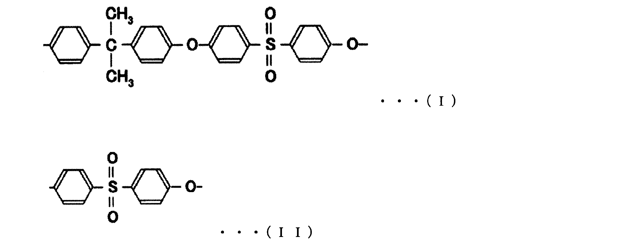
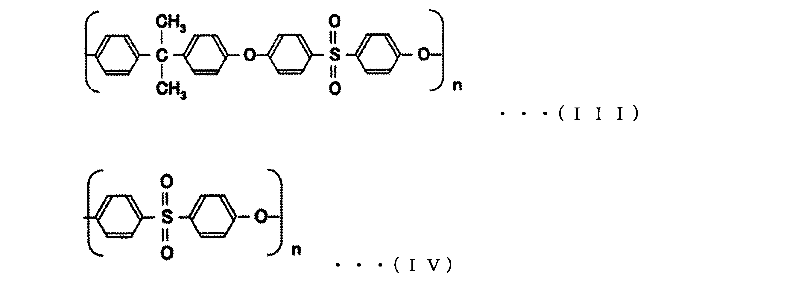
充填率(%)=膜面積×膜厚×100/筐体内部の体積 ・・・式(6)
充填率(%)=膜面積×膜厚×100/(筐体内部の体積-内芯の体積) ・・・式(7)
条件E:50≧SA/IA>1
SA:筒状筐体の導入口側における分離機能層a部の表面積
IA:筒状筐体の導出口側における筒状内芯の内側の表面積
条件EE:30≧SA/IA≧10
条件F:4000≧ALV/ILV≧30
ALV:筒状筐体の導入口側の分離機能層a部における線速度
ILV:筒状筐体の導出口側の筒状内芯における線速度
条件FF:1000≧SA/IA≧100
本発明の生物由来物質を含む精製液の製造方法は、平均細孔径Daを有する分離機能層a部に対して線速度を0.01~1.5m/Hourの範囲で被処理液を通液させて処理液Xを得る工程Xと、平均細孔径Dbを有する分離機能層b部に対して線速度を0.001~1.5m/Hourの範囲で上記処理液Xを通液させて処理液Yを得る工程Yと、分離機能層c部に対して線速度を0.00005~1.5m/Hourの範囲で上記処理液Yを通液させて精製液を得る工程Zと、を備え、上記平均細孔径Da、Db及びDcは、下記の条件A及びBを満たす。
条件A:30μm≧Da>Db>Dc≧0.01μm
条件B:6≧Da/Db≧2.8
不織布を250mm×250mmに切断した試験片について、各辺の中央部分をダイヤルシックネスゲージにより厚み(mm)を測定し、得られた値から平均値を算出した。なお、小数点第3位を四捨五入した値を用いた。
不織布を250mm×250mmに切断した試験片を3枚採取し、各試験片の質量を電子天秤にて測定し平均値を求め、該平均値を16倍して算出した。なお、小数点第1位を四捨五入することにより求めた。
走査型電子顕微鏡(以下「SEM」という、S-5500、株式会社日立ハイテクノロジー社製)を用いて不織布の表面を倍率3000倍で観察し、写真を撮影した。電子顕微鏡の測長機能を使用しピントが合い、かつ、融着のない繊維20本の繊維径(μm)を測定し、平均値を算出した。なお、小数点第2位を四捨五入した値を用いた。
不織布の試験片に試薬(GALWICK、表面張力15.9dyn/cm=15.9mN/m)を含浸させて完全に濡らし、試薬と不織布との接触角をゼロとした。上記試薬を含浸させた不織布の試験片を、自動細孔径分布測定器(型式:CFP-1200AEXCS、Porous materials,Inc社製)のホルダーにセットし、バブルポイント法(JIS K3832(1990))に従い、測定した。得られた差圧から下記式(1)を用いて最大細孔径を算出した。
最大細孔径(μm)=Cr/P ・・・式(1)
C:圧力定数(2860)
r:試薬の表面張力(15.9mN/m)
P:差圧(Pa)
なお、小数点第2位を四捨五入した値を用いた。
自動細孔径分布測定器(型式:CFP-1200AEXCS、Porous materials,Inc社製)に、乾燥した不織布の試験片を置き、一方の面にかける空気圧を徐々に増大させて、空気が乾燥試験片を透過するときの圧力と流量との関係を示す乾き流量曲線(DRY FLOW CURVE)を測定した。このとき、空気が乾燥試験片を透過し始めたときの圧力をP1とした。次いで、上記乾き流量曲線を基に、透過流量を1/2としたハーフドライ流量曲線を作成した。そして、上記試験片を試薬(GALWICK、表面張力15.9dyn/cm=15.9mN/m)に浸漬した後に、同様の測定を行い、濡れ流量曲線(WET FLOW CURVE)を得た。
平均細孔径(μm)=Cr/Pc ・・・式(2)
C:圧力定数(2860)
r:液体の表面張力(15.9mN/m)
Pc:差圧(P2-P1、Pa)
なお、小数点第2位を四捨五入した値を用いた。
乾燥した試験小片をホルダーに保持し、高分解能3DX線顕微鏡(型式:nano3DX、リガク・ホールディング社製)にて、X線源をCu、管電圧を40kV、管電流を30mAm、解像度を0.63μm/voxelの条件で観察し、画像を取り込み、画像処理ソフト(Avizo(ThermoFisherScientific社製))を用いてAmbientOcclusionを計算し、試料表面の形態に沿って輪郭を抽出し、試料内部の平均空隙率を算出した。
中空糸膜内蔵筐体の中空糸膜内側及び外側を蒸留水にて30分間洗浄した。中空糸膜内側に水圧16kPaをかけ、中空糸膜外側に流出してくる水の単位時間当たりの濾過量を測定した。透水性は下記式(3)で算出した。このとき、ハウジングに充填した中空糸膜の内、接着剤が付着していない部分の長さを測定し、膜面積の算出に用いた。
透水性(L/時間/kPa/m2)=Qw/(P×T×A) ・・・式(3)
Qw:濾過量(L)
T:流出時間(時間)
P:圧力(kPa)
A:膜面積(m2)
なお、小数点第1位を四捨五入した値を用いた。
中空糸膜を水に5分間浸漬した後に液体窒素で凍結し、凍結乾燥させた中空糸膜を測定試料とした。内表面を測定する場合は中空糸膜を半筒状に切断し、内表面が露出している状態とした。SEM(S-5500、株式会社日立ハイテクノロジー社製)を用いて、中空糸膜の分離機能層側表面を倍率5000倍で観察し、画像を取り込んだ。取り込む画像のサイズは640ピクセル×480ピクセルとした。15μm×15μmの範囲の孔について画像処理ソフト(ImageJ、開発元 アメリカ国立衛生研究所)を用いて、各細孔の直径を測定した。
平均細孔径(μm)=(細孔面積(μm2)/円周率)0.5×2 ・・・式(4)
なお、小数点第3位を四捨五入した値を平均細孔径とした。
中空糸膜を水に5分間浸漬した後に液体窒素で凍結して速やかに折り、中空糸膜の長手方向に垂直な断面を露出させた後、凍結乾燥した中空糸膜を測定試料とした。中空糸膜の断面をSEM(S-5500、株式会社日立ハイテクノロジーズ製)にて5000倍で観察し、構造体部分が密になっている方の表面側を画像の左側に配するように画像を取り込んだ。取り込む画像のサイズは640ピクセル×480ピクセルとした。
浮遊化したHEK293細胞を細胞密度が1.0×10⁶細胞/mLとなるようバイオリアクター(CR0003L200、Merck社製)内で3日間培養した。アデノ随伴ウイルス遺伝子をコードしたプラスミドを、遺伝子導入試薬を用いてトランスフェクションし、さらに培養を継続することでウイルス生産を行った。72時間後、Triton-X100とエンドヌクレアーゼを添加し、1時間撹拌することでアデノ随伴ウイルスを含む細胞破砕液を得た。
フィルターAの接触面積に対し流量を0.24mL/分/cm2に設定したポンプをフィルターユニットの導入口に接続し、さらにポンプとフィルターユニットの間に圧力測定ユニットを接続した状態で、200mLの細胞破砕液をろ過し、圧力上昇値を測定した。なお、圧力上昇値が140kPaを超えた場合はろ過を中止し、目詰まりが発生したと判断した。また、フィルターAの接触面積に対し処理液量(L/m2)を算出し、目詰まりの発生までに得た精製液についても、後述する「濁度測定」と「ウイルスベクター回収率測定」を実施した。
デジタル濁度計(TBD700、アズワン社製)を用いて各処理液を3回測定し、得られた値から、平均値を算出した。なお、小数点以下第2位を四捨五入した値を用いた。
アデノ随伴ウイルスベクターの力価定量キット(AAVpo Titration Kit(for Real Time PCR)、タカラバイオ社製)を用いて、細胞破砕液と精製液を測定し、得られた値から下記式(5)を用いてウイルスベクター回収率を求めた。
ウイルスベクター回収率(%)=精製液のウイルス力価(VG/mL)/細胞破砕液のウイルス力価(VG/mL)×100 ・・・式(5)
なお、小数点第1位を四捨五入した値を用いた。
ポリプロピレン(AchieveTM6936G2、Exxon Mobil社製)を原料とし、メルトブロー不織布製造装置を用い、ダイの設定温度を200℃、直径0.15mmの紡糸ノズル1穴当たりの吐出量を0.0075g/分とした。上記製造装置の紡糸ノズルの両側からは、加熱圧縮された空気(温度:175℃、単位面積当たりの噴出量:57Nm3/秒/m2)を吹き付け、上記記紡糸ノズルから100mmの距離の捕集装置に紡糸させ、目付を約15g/m2としたメルトブロー不織布B1を得た。
PSf(“ウルトラゾーン”(登録商標)S6010、BASF社製)15質量部とポリビニルピロリドン(以下「PVP」という、K-90:分子量120万、BASF社製)7質量部とジメチルアセトアミド(以下「DMAc」という)75質量部と水3質量部を溶解撹拌し、製膜原液を調製した。この製膜原液の37℃における粘度は10Pa・sであった。この製膜原液を37℃に保たれた外周スリット幅0.15mmの二重環ノズルの外管より吐出した。また、DMAc56質量部とPVP(BASF社製K-30:重量平均分子量4万)29質量部とグリセリン15質量部の注入液を内管から吐出した。
中空糸膜15本を、直径約5mm、長さ約12cmの筒状筐体に充填し、筒状筐体と中空糸膜の両端を“クイックメンダー”(登録商標、コニシ株式会社製)で固定した後、切断して開口することによって、中空糸膜内蔵筐体を作製した。
U字形状とした中空糸膜1200本を、直径約50mm、長さ45mmの筒状筐体に充填し、筒状筐体と中空糸膜端部をポリウレタン樹脂で固定した後、切断して開口することによって、U字化中空糸膜内蔵筐体を作製した。
分離機能層a部として不織布(“トレミクロン”(登録商標)、EM02010、東レ社製、以下「不織布A1」という)を3枚重ねたフィルターをフィルターAとし、直径47mm(有効膜面積1380mm2)の筐体に内蔵したフィルターA内蔵筐体、分離機能層b部として不織布B1を4枚重ねたフィルターをフィルターBとし、直径47mm(有効膜面積1380mm2)の筐体に内蔵したフィルターB内蔵筐体、分離機能層c部を有するフィルターCとして上述の中空糸膜C2を15本内蔵した中空糸膜内蔵筐体を用い、フィルターA、フィルターB、フィルターCの順に各筐体を連結したフィルターユニット1を作製した。また、不織布の平均空隙率は、不織布A1は81.1%、不織布B1は86.6%であった。
分離機能層a部として不織布A1を2枚重ねたフィルターをフィルターAとした以外は実施例1と同様にフィルターA、フィルターB、フィルターCの順に各筐体を連結したフィルターユニット2を作製した。
分離機能層b部として不織布B1を2枚重ねたフィルターをフィルターBとした以外は実施例1と同様にフィルターA、フィルターB、フィルターCの順に各筐体を連結したフィルターユニット3を作製した。フィルターユニット1による精製液の製造については、実施例1と同様の順序で被処理液を通液して、精製液を製造した。製造時の各分離機能層に対する線速度はフィルターAで0.14m/Hour、フィルターBで0.14m/Hour、フィルターCで0.12m/Hourであった。
中空糸膜C1を、分離機能層c部を有するフィルターCとした以外は実施例1と同様にフィルターA、フィルターB、フィルターCの順に各筐体を連結したフィルターユニット4を作製した。
1枚のポリプロピレン製の多孔性サポート材、分離機能層a部が3枚の不織布A1であるフィルターA、分離機能層b部が4枚の不織布B1であるフィルターB、1枚のポリプロピレン製サポート材の順に積層されるように、それぞれのロール原反(幅50cm×長さ50m)をレシプロ折機(型番3471、ホップテック株式会社製)に装着し、山高さを12mmとしたフィルターAとフィルターBが接合した後、プリーツを形成し、プリーツ折不織布を作製した。
ガラス繊維フィルター(ULTA Disc GF、47mm、5.0μm、Cytiva社製)1枚をフィルターAとした以外は実施例1と同様にフィルターA、フィルターB、フィルターCの順に各筐体を連結したフィルターユニット6を作製した。
分離機能層a部として“アクスター”(登録商標、G2200-1S BK0、東レ社製、以下「不織布A2」という)1枚をフィルターAとして用いた以外は実施例1と同様にフィルターA、フィルターB、フィルターCの順に各筐体を連結したフィルターユニット7を作製した。
PES膜フィルター(ULTA Disc HC、47mm、0.6μm/0.2μm、Cytiva社製)1枚を、0.6μm側をフィルターB、0.2μm側をフィルターCとして用い、直径47mm(有効膜面積1380mm2)の筐体に内蔵した以外は実施例1と同様にフィルターA、フィルターB、フィルターCの順に筐体を連結したフィルターユニット8を作製した。
分離機能層b部として不織布A1を3枚重ねたフィルターを、フィルターBとして用いた以外は実施例1と同様にフィルターA、フィルターB、フィルターCの順に各筐体を連結したフィルターユニット9を作製した。フィルターユニット9による精製液の製造については、実施例1と同様の順序で被処理液を通液して、精製液を製造した。製造時の各分離機能層に対する線速度はフィルターAで0.14m/Hour、フィルターBで0.14m/Hour、フィルターCで0.12m/Hourであった。
分離機能層a部として不織布A1を1枚としたフィルターを、フィルターAとして用いた以外は実施例1と同様にフィルターA、フィルターB、フィルターCの順に各筐体を連結したフィルターユニット10を作製した。
分離機能層b部として不織布B1を1枚としたフィルターを、フィルターBとして用いた以外は実施例1と同様にフィルターA、フィルターB、フィルターCの順に各筐体を連結したフィルターユニット11を作製した。
中空糸膜C3を、分離機能層c部を有するフィルターCとして用いた以外は実施例1と同様にフィルターA、フィルターB、フィルターCの順に各筐体を連結したフィルターユニット12を作製した。
中空糸膜C4を、分離機能層c部を有するフィルターCとして用いた以外は実施例1と同様にフィルターA、フィルターB、フィルターCの順にモジュールを連結したフィルターユニット13を作製した。
中空糸膜C5を、分離機能層c部を有するフィルターCとして用いた以外は実施例1と同様にフィルターA、フィルターB、フィルターCの順に各筐体を連結したフィルターユニット14を作製した。
分離機能層a部として不織布A1を3枚重ねたフィルターを用いて、直径47mm(有効膜面積1380mm2)の筐体に内蔵し、ビニルピロリドン/プロパン酸ビニルランダム共重合体(プロパン酸ビニルユニットのモル分率40%、数平均分子量16,500)を濃度50ppm、エタノールを濃度200ppmとなるように溶解した水溶液を筐体導入口から導出口に通液し、不織布全体にコーティングを行った。続いて、25kGyのγ線を照射し、ビニルピロリドン/プロパン酸ビニルランダム共重合体がコーティングされた不織布A3をフィルターAとした。
中空糸膜C6を、分離機能層c部を有するフィルターCとして用いた以外は実施例1と同様にフィルターA、フィルターB、フィルターCの順に各筐体を連結したフィルターユニット16を作製した。
不織布B3を、分離機能層b部を有するフィルターBとして用いた以外は実施例1と同様にフィルターA、フィルターB、フィルターCの順にモジュールを連結したフィルターユニット17を作製した。
分離機能層a部として不織布A1を30枚としたフィルターをフィルターAとして用いた以外は実施例1と同様にフィルターA、フィルターB、フィルターCの順に各筐体を連結したフィルターユニット18を作製した。
分離機能層b部として不織布B1を50枚としたフィルターをフィルターBとして用いた以外は実施例1と同様にフィルターA、フィルターB、フィルターCの順に各筐体を連結したフィルターユニット19を作製した。
分離機能層c部として不織布B1を4枚重ねたフィルターをフィルターCとして用い、直径47mm(有効膜面積1380mm2)の筐体に内蔵したフィルターC内蔵筐体を用いた以外は実施例1と同様にフィルターA、フィルターB、フィルターCの順に各筐体を連結したフィルターユニット20を作製した。

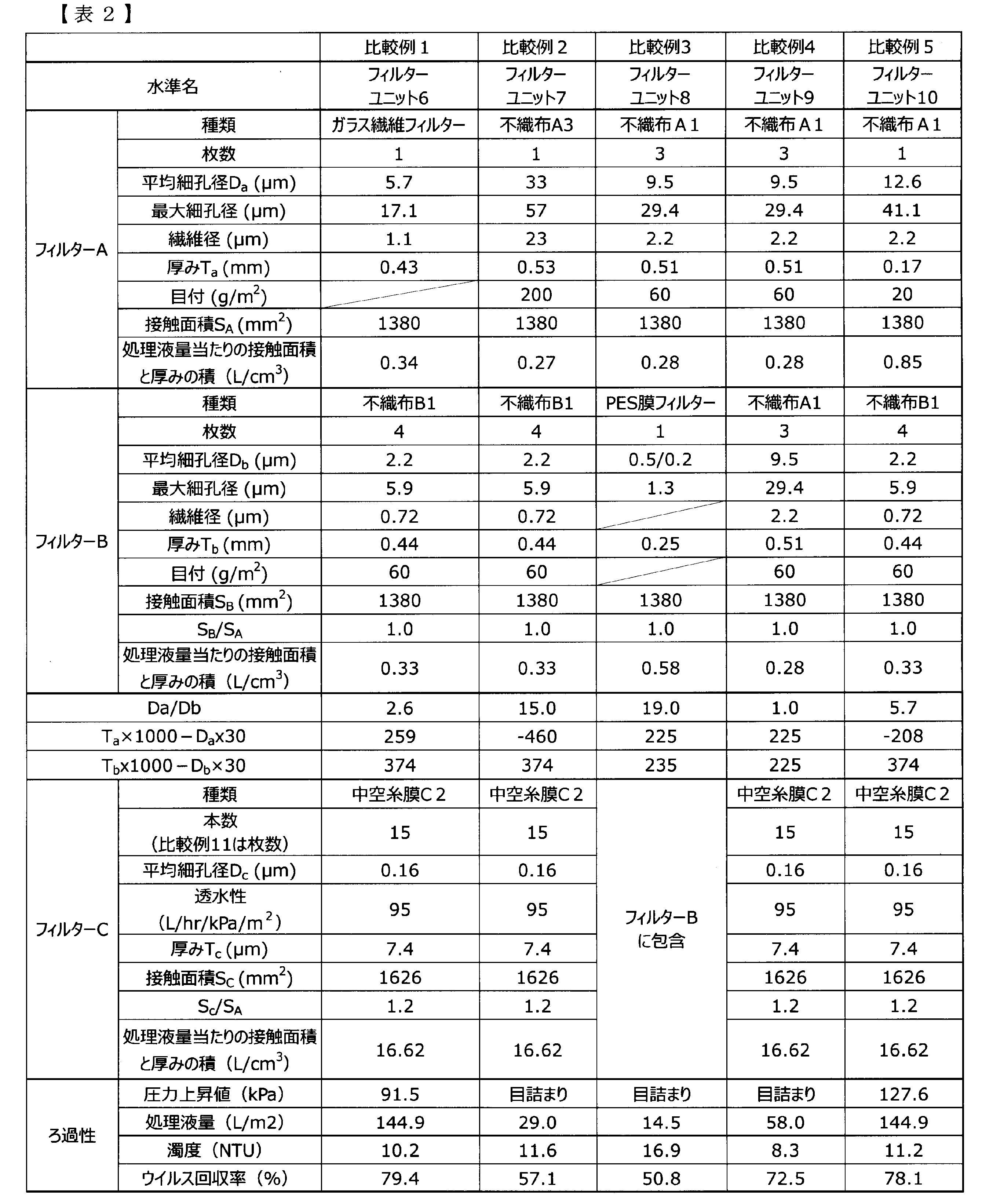


101 フィルターA(分離機能層a部;不織布)
102 フィルターB(分離機能層b部;不織布)
103 筒状筐体
104 フィルターC(分離機能層c部;中空糸膜)
105 接続部
106 筒状筐体
107 U字形状の中空糸膜
108 ポンプ
109 圧力計
110 筒状筐体
111 筒状内芯
200 フィルターA内蔵筐体
201 フィルターB内蔵筐体
202 中空糸膜内蔵筐体
203 フィルターA、フィルターB内蔵筐体
204 U字化中空糸膜内蔵筐体
205 フィルターA、フィルターB内蔵筒状筐体
300 フィルターユニット
301 精製装置
Claims (19)
- 平均細孔径Daを有する分離機能層a部、平均細孔径Dbを有する分離機能層b部及び平均細孔径Dcを有する分離機能層c部と、
前記分離機能層a部に被処理液を導入する導入口と、を備え、 前記平均細孔径Da、Db及びDcは、下記の条件A及びBを満たし、前記導入口から各分離機能層がa部、b部、c部の順に配置された、フィルターユニット。
条件A:30μm≧Da>Db>Dc≧0.01μm
条件B:6≧Da/Db≧2.8 - 前記分離機能層a部は厚みTaを有し、
前記分離機能層b部は厚みTbを有し、
該厚みTa及び該厚みTbの上限はそれぞれ5mm以下であり、下記の条件C及びDを満たす、請求項1記載のフィルターユニット。
条件C:厚みTaの下限/平均細孔径Da≧30
条件D:厚みTbの下限/平均細孔径Db≧30 - 前記分離機能層a部及び前記分離層b部は、繊維状フィルターであり、かつ、平均空隙率が70%以上95%以下である、請求項1又は2記載のフィルターユニット。
- 前記分離機能層c部は、モノカルボン酸ビニルエステルユニット、ビニルピロリドンユニット、ビニルカプロラクタムユニット、ビニルアセトアミドユニット及びアクリルアミドユニットからなる群から選択されるユニットを有する高分子を担持する、請求項1~3のいずれか一項記載のフィルターユニット。
- 前記分離機能層c部は、中空糸膜である、請求項1~4のいずれか一項記載のフィルターユニット。
- 前記分離機能層b部は、平均繊維径が0.3~1.5μmの不織布である、請求項1~5のいずれか一項記載のフィルターユニット。
- 前記分離機能層a部又は前記分離機能層b部の主成分は、ポリオレフィンである、請求項1~6のいずれか一項記載のフィルターユニット。
- 前記分離機能層a部又は前記分離機能層b部は、モノカルボン酸ビニルエステルユニット、ビニルピロリドンユニット、ビニルカプロラクタムユニット、ビニルアセトアミドユニット及びアクリルアミドユニットからなる群から選択されるユニットを有する高分子を担持する、請求項1~7のいずれか一項記載のフィルターユニット。
- 生物由来物質の精製用である、請求項1~8のいずれか一項記載のフィルターユニット。
- 導入口と導出口を有する筐体と、
前記分離機能層a部及び前記分離機能層b部は接合した状態で前記筐体に内蔵され、
前記分離機能層a部及び前記分離機能層b部の充填率は、30%以上95%以下である、請求項1~10のいずれか一項記載のフィルターユニット。 - 前記筐体は、筒状筐体であり、
前記筒状筐体に内蔵される筒状内芯を有し、
下記の条件Eを満たす、請求項10記載のフィルターユニット。
条件E:50≧SA/IA>1
SA:筒状筐体の導入口側における分離機能層a部の表面積
IA:筒状筐体の導出口側における筒状内芯の内側の表面積 - 前記筐体は、筒状筐体であり、
前記筒状筐体に内蔵される筒状内芯を有し、
前記分離機能層a部及び前記分離機能層b部は、プリーツを形成して内蔵され、
前記プリーツは、山高さが12mm以上30mm以下であり、山数が30以上70以下である、請求項10又は11記載のフィルターユニット。 - 前記筐体は、筒状筐体であり、
前記筒状筐体に内蔵される筒状内芯を有し、
下記の条件Fを満たす、請求項10~12のいずれか一項記載のフィルターユニット。
条件F:4000≧ALV/ILV≧30
ALV:筒状筐体の導入口側の分離機能層a部における線速度
ILV:筒状筐体の導出口側の筒状内芯における線速度 - 前記中空糸膜は、ポリスルホン系高分子を含み、
前記中空糸膜の内径が150μm以上1500μm以下であり、かつ、前記中空糸膜の膜厚が20μm以上300μm以下である、請求項5~13のいずれか一項記載のフィルターユニット。 - ポンプと、請求項1~14のいずれか一項記載のフィルターユニットと、圧力計を備え、
前記ポンプと前記フィルターユニットの導入口との接続部及び各フィルターが内蔵された各筐体の接続部に前記圧力計が接続されている、生物由来物質を精製する精製装置。 - バイオ医薬品精製用の請求項15記載の精製装置。
- 食品成分又は飲料成分精製用の請求項15記載の精製装置。
- 請求項15記載の精製装置により精製された、生体由来物質。
- 平均細孔径Daを有する分離機能層a部に対して線速度を0.01~1.5m/Hourの範囲で被処理液を通液させて処理液Xを得る工程Xと、
平均細孔径Dbを有する分離機能層b部に対して線速度を0.001~1.5m/Hourの範囲で前記処理液Xを通液させて処理液Yを得る工程Yと、
平均細孔径Dcを有する分離機能層c部に対して線速度を0.00005~1.5m/Hourの範囲で前記処理液Yを通液させて精製液を得る工程Zと、を備え、
前記平均細孔径Da、Db及びDcは、下記の条件A及びBを満たす、生物由来物質を含む精製液の製造方法。
条件A:30μm≧Da>Db>Dc≧0.01μm
条件B:6≧Da/Db≧2.8
Priority Applications (4)
| Application Number | Priority Date | Filing Date | Title |
|---|---|---|---|
| JP2024517037A JPWO2024190895A1 (ja) | 2023-03-15 | 2024-03-15 | |
| CN202480018511.8A CN120826270A (zh) | 2023-03-15 | 2024-03-15 | 过滤器单元、纯化装置和纯化液的制造方法 |
| EP24770997.5A EP4681804A1 (en) | 2023-03-15 | 2024-03-15 | Filter unit, purification device, and method for producing purified liquid |
| KR1020257020444A KR20250162763A (ko) | 2023-03-15 | 2024-03-15 | 필터 유닛, 정제 장치 및 정제액의 제조 방법 |
Applications Claiming Priority (4)
| Application Number | Priority Date | Filing Date | Title |
|---|---|---|---|
| JP2023040336 | 2023-03-15 | ||
| JP2023-040336 | 2023-03-15 | ||
| JP2023-166732 | 2023-09-28 | ||
| JP2023166732 | 2023-09-28 |
Publications (1)
| Publication Number | Publication Date |
|---|---|
| WO2024190895A1 true WO2024190895A1 (ja) | 2024-09-19 |
Family
ID=92755359
Family Applications (1)
| Application Number | Title | Priority Date | Filing Date |
|---|---|---|---|
| PCT/JP2024/010177 Ceased WO2024190895A1 (ja) | 2023-03-15 | 2024-03-15 | フィルターユニット、精製装置及び精製液の製造方法 |
Country Status (5)
| Country | Link |
|---|---|
| EP (1) | EP4681804A1 (ja) |
| JP (1) | JPWO2024190895A1 (ja) |
| KR (1) | KR20250162763A (ja) |
| CN (1) | CN120826270A (ja) |
| WO (1) | WO2024190895A1 (ja) |
Citations (7)
| Publication number | Priority date | Publication date | Assignee | Title |
|---|---|---|---|---|
| JPH05329206A (ja) * | 1992-05-29 | 1993-12-14 | Terumo Corp | 液体用濾過器 |
| WO2010060719A1 (en) | 2008-11-03 | 2010-06-03 | Crucell Holland B.V. | Method for the production of adenoviral vectors |
| US20120292247A1 (en) * | 2010-01-19 | 2012-11-22 | Kyunghee Moon | Complex filter and water purifier including complex filter |
| JP2017529070A (ja) | 2014-08-27 | 2017-10-05 | サイオクサス セラピューティクス リミテッド | アデノウイルスの製造方法 |
| JP2019166520A (ja) * | 2018-03-23 | 2019-10-03 | 東レ株式会社 | バイオ医薬品精製システム |
| WO2021100804A1 (ja) * | 2019-11-21 | 2021-05-27 | 東レ株式会社 | 多孔質分離膜 |
| WO2022202603A1 (ja) * | 2021-03-26 | 2022-09-29 | 東レ株式会社 | 多孔質吸着材料、およびそれを用いたバイオ医薬品精製用分離カラム、ならびに、バイオ医薬品の製造方法 |
-
2024
- 2024-03-15 WO PCT/JP2024/010177 patent/WO2024190895A1/ja not_active Ceased
- 2024-03-15 EP EP24770997.5A patent/EP4681804A1/en active Pending
- 2024-03-15 JP JP2024517037A patent/JPWO2024190895A1/ja active Pending
- 2024-03-15 KR KR1020257020444A patent/KR20250162763A/ko active Pending
- 2024-03-15 CN CN202480018511.8A patent/CN120826270A/zh active Pending
Patent Citations (7)
| Publication number | Priority date | Publication date | Assignee | Title |
|---|---|---|---|---|
| JPH05329206A (ja) * | 1992-05-29 | 1993-12-14 | Terumo Corp | 液体用濾過器 |
| WO2010060719A1 (en) | 2008-11-03 | 2010-06-03 | Crucell Holland B.V. | Method for the production of adenoviral vectors |
| US20120292247A1 (en) * | 2010-01-19 | 2012-11-22 | Kyunghee Moon | Complex filter and water purifier including complex filter |
| JP2017529070A (ja) | 2014-08-27 | 2017-10-05 | サイオクサス セラピューティクス リミテッド | アデノウイルスの製造方法 |
| JP2019166520A (ja) * | 2018-03-23 | 2019-10-03 | 東レ株式会社 | バイオ医薬品精製システム |
| WO2021100804A1 (ja) * | 2019-11-21 | 2021-05-27 | 東レ株式会社 | 多孔質分離膜 |
| WO2022202603A1 (ja) * | 2021-03-26 | 2022-09-29 | 東レ株式会社 | 多孔質吸着材料、およびそれを用いたバイオ医薬品精製用分離カラム、ならびに、バイオ医薬品の製造方法 |
Non-Patent Citations (1)
| Title |
|---|
| See also references of EP4681804A1 |
Also Published As
| Publication number | Publication date |
|---|---|
| EP4681804A1 (en) | 2026-01-21 |
| JPWO2024190895A1 (ja) | 2024-09-19 |
| CN120826270A (zh) | 2025-10-21 |
| KR20250162763A (ko) | 2025-11-19 |
Similar Documents
| Publication | Publication Date | Title |
|---|---|---|
| JP5496901B2 (ja) | 清澄化されたバイオ医薬培養液を製造するための多孔質中空糸膜の使用 | |
| CA2921827C (en) | Porous membrane, blood purifying module incorporating porous membrane, and method for producing porous membrane | |
| JP6522001B2 (ja) | 中空糸濾過膜 | |
| US20040050791A1 (en) | Asymmetric hollow fiber membranes | |
| CN113842792A (zh) | 一种除病毒用不对称的pes滤膜及其制备方法 | |
| WO2004024216A1 (ja) | 血漿浄化膜及び血漿浄化システム | |
| JP5909765B2 (ja) | 高スループットの膜 | |
| CA2473246A1 (en) | Convoluted surface hollow fiber membranes | |
| KR20150068216A (ko) | Pva 코팅된 중공사 복합막 및 이의 제조방법 | |
| JP5909766B2 (ja) | チャネルを有する高スループットの膜 | |
| WO2024190895A1 (ja) | フィルターユニット、精製装置及び精製液の製造方法 | |
| JP4103037B2 (ja) | 透析液清浄化用中空糸膜およびその製造方法 | |
| JPH05245350A (ja) | 中空糸状高性能精密濾過膜 | |
| JP2026053971A (ja) | フィルターユニット、精製装置及び精製液の製造方法 | |
| JP2026053970A (ja) | フィルターユニット、精製装置及び精製液の製造方法 | |
| JPWO2016182015A1 (ja) | 多孔質中空糸膜及びその製造方法 | |
| JPH0211263B2 (ja) | ||
| JP2004121922A (ja) | 中空糸膜 | |
| JP7194656B2 (ja) | 多孔質膜 | |
| JP2011020071A (ja) | ポリスルホン系中空糸膜の製造方法 | |
| JP2022170736A (ja) | 分離膜 | |
| AU2002236863A1 (en) | Asymmetric Hollow Fiber Membranes |
Legal Events
| Date | Code | Title | Description |
|---|---|---|---|
| WWE | Wipo information: entry into national phase |
Ref document number: 2024517037 Country of ref document: JP |
|
| 121 | Ep: the epo has been informed by wipo that ep was designated in this application |
Ref document number: 24770997 Country of ref document: EP Kind code of ref document: A1 |
|
| WWE | Wipo information: entry into national phase |
Ref document number: 202480018511.8 Country of ref document: CN |
|
| WWE | Wipo information: entry into national phase |
Ref document number: 2024770997 Country of ref document: EP |
|
| NENP | Non-entry into the national phase |
Ref country code: DE |
|
| WWP | Wipo information: published in national office |
Ref document number: 202480018511.8 Country of ref document: CN |
|
| WWE | Wipo information: entry into national phase |
Ref document number: 11202505823S Country of ref document: SG |
|
| WWP | Wipo information: published in national office |
Ref document number: 11202505823S Country of ref document: SG |
|
| ENP | Entry into the national phase |
Ref document number: 2024770997 Country of ref document: EP Effective date: 20251015 |
|
| ENP | Entry into the national phase |
Ref document number: 2024770997 Country of ref document: EP Effective date: 20251015 |
|
| ENP | Entry into the national phase |
Ref document number: 2024770997 Country of ref document: EP Effective date: 20251015 |
|
| ENP | Entry into the national phase |
Ref document number: 2024770997 Country of ref document: EP Effective date: 20251015 |
|
| ENP | Entry into the national phase |
Ref document number: 2024770997 Country of ref document: EP Effective date: 20251015 |