WO2024201744A1 - スクリーン装置 - Google Patents
スクリーン装置 Download PDFInfo
- Publication number
- WO2024201744A1 WO2024201744A1 PCT/JP2023/012633 JP2023012633W WO2024201744A1 WO 2024201744 A1 WO2024201744 A1 WO 2024201744A1 JP 2023012633 W JP2023012633 W JP 2023012633W WO 2024201744 A1 WO2024201744 A1 WO 2024201744A1
- Authority
- WO
- WIPO (PCT)
- Prior art keywords
- screen
- slide bar
- frame
- guide
- slide
- Prior art date
- Legal status (The legal status is an assumption and is not a legal conclusion. Google has not performed a legal analysis and makes no representation as to the accuracy of the status listed.)
- Ceased
Links
Images


Classifications
-
- E—FIXED CONSTRUCTIONS
- E06—DOORS, WINDOWS, SHUTTERS, OR ROLLER BLINDS IN GENERAL; LADDERS
- E06B—FIXED OR MOVABLE CLOSURES FOR OPENINGS IN BUILDINGS, VEHICLES, FENCES OR LIKE ENCLOSURES IN GENERAL, e.g. DOORS, WINDOWS, BLINDS, GATES
- E06B9/00—Screening or protective devices for wall or similar openings, with or without operating or securing mechanisms; Closures of similar construction
- E06B9/52—Devices affording protection against insects, e.g. fly screens; Mesh windows for other purposes
- E06B9/54—Roller fly screens
- E06B2009/543—Horizontally moving screens
-
- E—FIXED CONSTRUCTIONS
- E06—DOORS, WINDOWS, SHUTTERS, OR ROLLER BLINDS IN GENERAL; LADDERS
- E06B—FIXED OR MOVABLE CLOSURES FOR OPENINGS IN BUILDINGS, VEHICLES, FENCES OR LIKE ENCLOSURES IN GENERAL, e.g. DOORS, WINDOWS, BLINDS, GATES
- E06B9/00—Screening or protective devices for wall or similar openings, with or without operating or securing mechanisms; Closures of similar construction
- E06B9/56—Operating, guiding or securing devices or arrangements for roll-type closures; Spring drums; Tape drums; Counterweighting arrangements therefor
- E06B9/58—Guiding devices
- E06B9/581—Means to prevent or induce disengagement of shutter from side rails
-
- E—FIXED CONSTRUCTIONS
- E06—DOORS, WINDOWS, SHUTTERS, OR ROLLER BLINDS IN GENERAL; LADDERS
- E06B—FIXED OR MOVABLE CLOSURES FOR OPENINGS IN BUILDINGS, VEHICLES, FENCES OR LIKE ENCLOSURES IN GENERAL, e.g. DOORS, WINDOWS, BLINDS, GATES
- E06B9/00—Screening or protective devices for wall or similar openings, with or without operating or securing mechanisms; Closures of similar construction
- E06B9/56—Operating, guiding or securing devices or arrangements for roll-type closures; Spring drums; Tape drums; Counterweighting arrangements therefor
- E06B9/58—Guiding devices
- E06B9/582—Means to increase gliss, light, sound or thermal insulation
Definitions
- the present invention relates to a screen device that can be used as a light blocking or light adjusting device such as curtains or blinds, or as a screen door or partition.
- this type of screen device generally comprises a hollow doorstop frame and storage frame arranged opposite each other, a hollow slide bar arranged on the same plane as the doorstop frame and storage frame and sliding between the doorstop frame and the storage frame on both the doorstop frame side and the storage frame side, a screen with one end fixed to the slide bar that is pulled out from inside the storage frame as the slide bar slides towards the doorstop frame and unfolds on the same plane as the doorstop frame and storage frame, and a slide guide that guides the sliding of the slide bar.
- the sliding direction of the slide bar is the width direction
- the direction perpendicular to the width direction in the same plane on which the doorstop frame, storage frame, and slide bar are arranged is the height direction
- the direction perpendicular to both the width direction and the height direction is the depth direction
- the slide guide is formed by connecting a plurality of guide units, each guide unit having a pair of side walls arranged opposite each other in the depth direction and a bottom wall connecting both side walls, each side wall having a pin at one end in the width direction that protrudes outward in the depth direction and an opening at the other end in the width direction
- two adjacent guide units are arranged so that one guide unit can pivot relative to the other guide unit by loosely fitting each pin of the other guide unit into each opening of the other guide unit, and the slide guide has flexibility.
- a rail portion is provided on the inner depth-wise portion of each side wall of each guide unit, and the rail portion extends along a line connecting the centers of the pins of each guide unit in the direction in which the guide units are connected, and a support portion that protrudes inward in the depth-wise direction is provided on the edge portion of each side wall that is further up in the height direction from the bottom wall than the rail portion.
- a screen removal member is attached to the inside of the slide guide in the depth direction, with multiple needle-shaped parts attached at intervals to the base part that is inserted between the rail part and the support part of each guide unit of the slide guide and that extends in the width direction and has flexibility.
- the screen removal member is attached to the inside of the slide guide in the depth direction, in a freely detachable manner.
- the needle-shaped portion of the screen removal member pierces the lower end of the screen in the height direction as it is pulled out from inside the storage frame and unfolds in the width direction, preventing the lower end of the screen in the height direction from coming off the slide guide, and as the slide bar slides towards the storage frame, the needle-shaped portion of the screen removal member comes off the lower end of the screen in the height direction, and the screen is stored inside the storage frame.
- the screen device described in Patent Document 1 a screen removal prevention member having a needle-shaped portion attached to a base according to the material of the screen is prepared in advance, and the screen removal prevention member can be attached to the inside of the depth direction of both side walls of each guide unit of the slide guide. Therefore, the screen device described in Patent Document 1 has the advantage that damage to the lower end portion of the screen in the height direction is suppressed even if the needle-shaped portion of the screen removal prevention member is repeatedly pierced into and removed from the lower end portion of the screen in the height direction when the screen unfolds in the width direction as the slide bar slides in the width direction and is stored in the storage frame.
- the multiple needle-shaped portions of the screen removal member are spaced apart, there are gaps between adjacent needle-shaped portions.
- external pressure such as wind pressure from the outside to the inside in the depth direction
- it bends in the direction in which the external pressure is received but it cannot be said with certainty that the needle-shaped portion of one of the screen removal members that was stuck into the lower end of the bent screen in the height direction will not come out of the lower end of the screen in the height direction. If the needle-shaped portion of the screen removal member comes out of the lower end of the screen in the height direction, the lower end of the screen in the height direction will no longer be prevented from coming out of the slide guide.
- the present invention aims to provide a screen device that effectively prevents wear on the lower end of the screen in the vertical direction caused by repeated piercing and removal of the needle-shaped parts of the screen removal member, prevents foreign matter from accumulating on the upper surface in the vertical direction of the bottom wall of each guide unit of the slide guide, and can maintain the lower end of the screen in the vertical direction from being removed from the slide guide even if the screen is deflected by external pressure.
- the present invention provides a screen device comprising: a hollow doorstop frame and storage frame arranged opposite each other; a hollow slide bar arranged on the same plane as the doorstop frame and storage frame and sliding between the doorstop frame and the storage frame on both the doorstop frame side and the storage frame side; a screen having one end fixed to the slide bar and pulled out from inside the storage frame as the slide bar slides towards the doorstop frame side and unfolds on the same plane as the doorstop frame and storage frame; and a slide guide for guiding the sliding of the slide bar,
- the sliding direction of the slide bar is defined as the width direction
- the direction perpendicular to the width direction in the same plane on which the doorstop frame, storage frame and slide bar are arranged is defined as the height direction
- the direction perpendicular to both the width direction and the height direction is defined as the depth direction
- the doorstop frame, storage frame and slide bar each extend in the height direction
- the slide guide is formed by connecting a plurality of guide units, and each guide unit has
- a screen removal member is provided on the inside of the depth direction of the slide guide, and a number of needle-shaped parts protruding inward in the depth direction of the slide guide are attached at intervals to a base part that extends in the width direction and has a bendability and is inserted between the rail part and the support part of each guide unit of the slide guide.
- the screen removal member is removably attached to the inside of the depth direction of the slide guide, and as the slide bar slides toward the door stop frame side, the needle-shaped parts of the screen removal member pierce the lower end part in the height direction of the screen that is pulled out from inside the storage frame and expanded in the width direction, and the lower end part in the height direction of the screen is pulled out of the storage frame and expanded in the width direction.
- the needle-shaped part of the screen removal member comes off from the lower end of the screen in the height direction, and the screen is stored inside the storage frame.
- a roller pipe that is rotatable and extends in the height direction and has a built-in coil spring that accumulates elastic force is stored inside the storage frame, and the other end of the screen is fixed to the height direction part of the outer periphery of the roller pipe, and the roller pipe rolls up the screen on the outer periphery by releasing the elastic force accumulated in the coil spring.
- One end of the slide guide is a free end that is stored inside the slide bar, and the other end is fixed to the lower end of the storage frame in the height direction.
- the slide guide As the slide bar slides toward the door stop frame, the slide guide is pulled out from the lower end of the slide bar in the height direction toward the storage frame.
- the portion of the slide guide pulled out from the slide bar maintains linearity in the width direction, and as the slide bar slides toward the storage frame when the screen is wound up around the outer circumferential surface of the roller pipe due to the release of the elastic force accumulated in the coil spring, the slide guide moves from the inside of the slide bar to the
- the screen is housed in the slide guide from the lower end in the length direction and moves upward in the length direction inside the slide bar, the screen removal member is attached to the inner depth direction of one side wall of each guide unit of the slide guide, and a flexible cover member is attached to the inner depth direction of the other side wall of each guide unit of the slide guide, and a band-shaped cover part that protrudes inward in the depth direction of the slide guide is provided on a supported part extending in the width direction that is inserted between the rail part and the support part of each guide unit of the slide guide, the
- a screen removal prevention member is attached to the inside depth of one side wall of each guide unit of the slide guide, so that as the slide bar slides widthwise, it unfolds in the widthwise direction, and the needle-shaped portion of the screen removal prevention member pierces the lower end of the screen in the height direction stored inside the storage frame and then comes out, and even if this piercing and coming out is repeated, wear on the lower end of the screen in the height direction can be effectively suppressed.
- a cover member is attached to the inside depth of the other side wall of each guide unit of the slide guide, so that the bottom wall of each guide unit of the slide guide is covered from above by the cover portion of the cover member.
- the needle-shaped portion of the screen removal member remains stuck in the lower end of the screen in the height direction, or even if it comes off, it will stick into it again, and the lower end of the screen in the height direction is kept from being removed from the slide guide.
- the cover part of the cover member can reliably move the lower end of the screen in the height direction toward the needle-shaped portion of the screen removal member.
- the cover member is formed from a material that does not wear down the screen and has a hardness that moves the lower end of the screen in the height direction toward the needle-shaped portion of the screen removal member when the tip on the inside of the depth direction of the cover portion comes into contact with the screen. This makes it possible to more effectively suppress wear down of the lower end of the screen in the height direction that unfolds in the width direction as the slide bar slides in the width direction and is stored inside the storage frame. It also makes it possible to more effectively realize the movement of the lower end of the screen in the height direction toward the needle-shaped portion of the screen removal member by the cover portion of the cover member.
- the cover portion of the cover member extends obliquely upward in the height direction from the boundary with the supported portion to the tip on the inside in the depth direction.
- a tension member having one end and the other end, one end of which is fixed to the free end side of the slide guide, which passes through the inside of the slide bar and is pulled out from the upper end of the slide bar in the height direction to the doorstop frame side, and which is pulled into the inside of the doorstop frame from the upper end of the doorstop frame in the height direction, and the other end of which is fixed to the inner surface of the doorstop frame.
- the tension member cooperates with the slide bar to slide the slide bar parallel to both the doorstop frame and the storage frame.
- the parallel sliding of the slide bar relative to both the doorstop frame and the storage frame is also achieved when the slide bar slides toward the storage frame side.
- the wiring of the tension member is simplified, making it easier to manufacture the screen device.
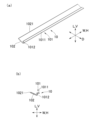
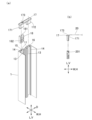
- FIG. 1 is a partially cutaway cross-sectional view showing an embodiment of a screen unit of the present invention.
- 2 is a widthwise cross-sectional view of a door stop frame and a slide bar of the screen device shown in FIG. 1 .
- 2 is a widthwise cross-sectional view of a storage frame of the screen device shown in FIG. 1 .
- Fig. 2A is a perspective view of a main portion showing a portion of a slide guide of the screen device shown in Fig. 1 that is located on the storage frame side
- Fig. 2B is a cross-sectional view in the height direction of the slide guide shown in Fig. 2A.
- 5A is a perspective view of the cover member shown in Fig. 4.
- FIG. 4 is a perspective view of the cover member shown in Fig. 4.
- FIG. 5B is a front view of the cover member shown in Fig. 5A.
- 1A is an exploded perspective view of a door stop frame
- FIG. 1B is a cross-sectional view of a main part showing a method of passing a tension member through the door stop frame and fixing the tension member to the door stop frame.
- the screen unit SA of this embodiment comprises hollow doorstop frame 1 and storage frame 2 arranged opposite each other, and hollow slide bar 3 arranged on the same plane as doorstop frame 1 and storage frame 2, sliding between doorstop frame 1 and storage frame 2 on both sides of doorstop frame 1 and storage frame 2.
- the sliding direction of slide bar 3 is defined as width direction W of screen unit SA
- the direction perpendicular to width direction W in the same plane on which doorstop frame 1, storage frame 2 and slide bar 3 are arranged is defined as height direction L of screen unit SA
- the direction perpendicular to both width direction W and height direction L is defined as depth direction D of screen unit SA.
- width direction W and height direction L correspond to horizontal direction H and vertical direction V, respectively.
- the doorstop frame 1, storage frame 2, and slide bar 3 all extend in the vertical direction V, the doorstop frame 1 and storage frame 2 are arranged on the same vertical plane, and the slide bar 3 slides in the horizontal direction H within the same vertical plane on which the doorstop frame 1 and storage frame 2 are arranged.
- the screen device SA also includes a screen 4, one end of which is fixed to the slide bar 3, which is pulled out from inside the storage frame 2 as the slide bar 3 slides toward the doorstop frame 1, and which unfolds in the same vertical plane as the doorstop frame 1 and the storage frame 2, and a slide guide 5 that guides the sliding of the slide bar 3.
- the doorstop frame 1 has one end face in the horizontal direction H located on the sliding bar 3 side open, and can receive inside one end in the horizontal direction H on the doorstop frame 1 side of the sliding bar 3 sliding towards the doorstop frame 1 side.
- a pair of support pieces 11, 11 are provided at a distance in the depth direction D of the doorstop frame 1, protruding inward in the horizontal direction H of the doorstop frame 1 and extending in the vertical direction V, with their tips bent inward in the depth direction D.
- a first retaining member 12 is attached inside the other end in the horizontal direction H of the doorstop frame 1, with one end inserted from above or below the doorstop frame 1 into a hollow space surrounded by the pair of support pieces 11, 11 and the inner surface of the doorstop frame 1 located between these support pieces 11, 11.
- a first protrusion 13 is provided that is bent outward in the depth direction D and extends in the vertical direction V.
- a second protrusion 14 is provided that protrudes inward in the depth direction D from both inner surfaces facing the depth direction D and extends in the vertical direction V, facing the first protrusion 13.
- the first protrusion 13 and the second protrusion 14 divide the inside of the horizontal direction H of the other end of the door stop frame 1 into a first insertion portion 15 and a second insertion portion 16.
- the slide bar 3 comprises a hollow main body 31 and a hollow first screen mounting portion 32 that protrudes from the main body 31 in the horizontal direction H on the side opposite the doorstop frame 1.
- One end of the main body 31 in the horizontal direction H located on the doorstop frame 1 side is an open surface 311, and a cover 312 that covers the open surface 311 from the outside in the horizontal direction H is removably attached to this end in the horizontal direction H.
- a recess that is recessed inward in the horizontal direction H is provided in the center of the depth direction D of the cover 312, and a second retaining member 313 that protrudes outward in the horizontal direction H of the main body 31 is attached by having one end inserted into this recess from above or below the main body 31.
- Magnets or components with built-in magnets can be used for the first holding member 12 of the doorstop frame 1 and the second holding member 313 of the body 31 of the slide bar 3.
- the second holding member 313 is attracted to the first holding member 12 by magnetic force, and the sliding limit of the slide bar 3 toward the doorstop frame 1 is determined, and the sliding of the slide bar 3 stops at the sliding limit on the doorstop frame 1 side, so that the stopped state of the slide bar 3 at the doorstop frame 1 is stably maintained.
- a pair of third protrusions 321, 321 protruding inward in the depth direction D are provided at the end of the first screen mounting portion 32 opposite the main body 31, and a first partition wall 322 extending in the vertical direction V is provided further inward in the horizontal direction H than the third protrusions 321, 321.
- a storage section 323 that is open outward in the horizontal direction H is defined in the first screen mounting portion 32 by the pair of third protrusions 321, 321, both inner surfaces of the first screen mounting portion 32 facing the depth direction D, and the first partition wall 322.
- a first fixing member 41 is attached to one end of the screen 4 that is fixed to the slide bar 3.
- the first fixing member 41 is inserted between the pair of third protrusions 321, 321 into the storage section 323 of the first screen mounting section 32 of the slide bar 3, and is engaged with the pair of third protrusions 321, 321, thereby fixing one end of the screen 4 to the slide bar 3.
- the storage frame 2 also houses a roller pipe 21 extending in the vertical direction V inside.
- the roller pipe 21 comprises a cylindrical main body 211, a bearing 212 fitted into the lower end of the main body 211, and a rotating shaft 213 fixed to the upper end of the bearing 212 and extending partway in the vertical direction V of the roller pipe 21.
- a first cap 214 having a threaded groove engraved on its upper end is fitted into the upper end of the roller pipe 21.
- a lid 215 having an opening into which the upper end of the first cap 214 is inserted is disposed at the upper end of the storage frame 2, and the lid 215 is fixed to the upper end of the storage frame 2 by a screw 216. Therefore, the roller pipe 21 is supported at its lower end by the bearing 212 and at its upper end by the storage frame 2 via the first cap 214, so that it can rotate freely around the rotating shaft 213.
- a coil spring 217 is built into the roller pipe 21, and the coil spring 217 is disposed radially outward of the rotating shaft 213.
- a groove 211a extending in the vertical direction V is formed on the outer peripheral surface of the main body 211 of the roller pipe 21, and a second partition wall 211b extending in the vertical direction V along the groove 211a is provided inside the main body 211 of the roller pipe 21.
- the second partition wall 211b divides the second screen mounting frame portion 211c inside the main body 211 of the roller pipe 21.
- a second fixing member 42 is attached to the other end of the screen 4 located opposite to the one end attached to the slide bar 3 in the horizontal direction H.
- the second fixing member 42 is inserted into the second screen mounting portion 211c through the groove 211a and engaged with the second screen mounting portion 211c, thereby fixing the other end of the screen 4 to the main body 211 of the roller pipe 21.
- the screen 4 can be wound around the outer peripheral surface of the main body 211 of the roller pipe 21.
- the coil spring 217 is set so that an elastic force is accumulated when the slide bar 3 slides toward the door stop frame 1. Therefore, when the elastic force accumulated in the coil spring 217 is released, the screen 4 is wound up on the outer circumferential surface of the roller pipe body 211, and the slide bar 3 to which the above-mentioned one end of the screen 4 is fixed slides toward the storage frame 2. When the first screen mounting portion 32 abuts against the storage frame 2, the sliding of the slide bar 3 toward the storage frame 2 stops.
- Such a screen device SA is installed, for example, in an opening of a window frame, door frame, etc. of a building.
- the doorstop frame 1 is fixed to a frame located at one end of the horizontal direction H of the opening
- the storage frame 2 is fixed to a frame located at the other end of the horizontal direction H of the opening.
- the screen device SA is provided with an upper rail 6 extending in the horizontal direction H at the upper end of the opening, and a lower rail 7 extending in the horizontal direction H at the lower end of the opening.
- the upper rail 6 is a hollow member with a U-shaped cross section in the vertical direction V, and the slide bar 3 is inserted inside the upper rail 6.
- the upper end of the screen 4, which is pulled out from the storage frame 2 and deployed when the slide bar 3 slides toward the doorstop frame 1, is also inserted inside the upper rail 6.
- the lower rail 7 is a linear member extending in the horizontal direction H.
- a wheel 33 is pivoted in the depth direction D and rotatably provided at the lower end of the body 31 of the slide bar 3. As the slide bar 3 slides in the horizontal direction H, the wheel 33 rolls on the lower rail 7.
- the slide guide 5 guides the sliding of the slide bar 3 in the horizontal direction H.
- the slide guide 5 also assists the sliding of the slide bar 3 in the horizontal direction H to be parallel to the doorstop frame 1 and the storage frame 2.
- the slide guide 5 is formed by connecting a plurality of guide units 51.
- Each guide unit 51 has a pair of side walls 511, 511 arranged opposite each other in the depth direction D, and a bottom wall 512 connecting both side walls 511, 511.
- Each side wall 511 is provided with a pin 511a at one end in the horizontal direction H that protrudes outward in the depth direction D, and an opening 511b at the other end in the horizontal direction H.
- the pin 511a and the opening 511b are located at the upper end of each guide unit 51 at the same height from the lower end of the side wall 511.
- two adjacent guide units 51, 51 are loosely fitted into the openings 511b of one guide unit 51 with the pins 511a of the other guide unit 51, so that one guide unit 51 can pivot relative to the other guide unit 51, and the slide guide 5 has flexibility.
- each side wall 511 of each guide unit 51 a first recess 511c is formed around each pin 511a, recessed inward in the depth direction D.
- the length of each pin 511a is the same as the recess width of the first recess 511c, and the outer diameter of each pin 511a and the inner diameter of each opening 511b are sized so that each pin 511a can be loosely fitted into each opening 511b.
- the periphery of each opening 511b is cut out leaving the upper edge of each side wall 511 to form a first notch 511d, and the upper edge is a protruding piece 511e extending away from the opening 511b.
- first recess 511c has a ridge 511f that protrudes upward at its lower end.
- second recess 511g is formed at the lower end of each side wall 511 below the first recess 511c, with the same recess width as the first recess 511c.
- the bottom wall 512 is disposed at a position corresponding to the upper end of the second recess 511g of both side walls 511, 511.
- the pivot range of two adjacent guide units 51, 51 is from the position where the lower end of the side walls 511, 511 of one guide unit 51 contacts the lower end of the side walls 511, 511 of the other guide unit 51 to the position where each protruding portion 511e of each side wall 511, 511 of one guide unit 51 contacts each mountain portion 511f of each first recessed portion 511c formed on each side wall 511, 511 of the other guide unit 51.
- each pin 511a is the same as the recess width of the first recess 511c, so the outer end surface in the depth direction D of each pin 511a is arranged flush with the outer surface in the depth direction D of the upper end of each side wall 511.
- each of the side walls 511, 511 of each guide unit 51 is recessed inward in the depth direction D, forming a recess 511h.
- one end of the slide guide 5 is a free end 513 stored inside the slide bar 3, and the other end is a fixed end 514 fixed to the lower end of the storage frame 2.
- the slide guide 5 is pulled out from the lower end of the slide bar 3 toward the storage frame 2, and the part of the slide guide 5 pulled out from the slide bar 3 maintains linearity in the horizontal direction H.
- the slide guide 5 is stored inside the slide bar 3 from the lower end of the slide bar 3, bends upward, and moves upward inside the slide bar 3.
- an arch-shaped protrusion 34 that protrudes inward in the depth direction D is provided on each inner surface in the depth direction D of the lower end of the slide bar 3.
- the protrusion 34 can be inserted into a recess 511h formed in each guide unit 51 of the slide guide 5, and the pivoting of each guide unit 51 is guided by the protrusion 34 when the protrusion 34 is inserted into the recess 511h.
- the free end 513 of the slide guide 5 is connected to an adjuster 8 that moves up and down inside the slide bar 3.
- the adjuster 8 has a rod-shaped weight 81 built in that extends up and down.
- the gravity acting on the weight 81 acts on the part of the slide guide 5 stored inside the slide bar 3, and when the slide bar 3 is slid toward the door stop frame 1, it helps the slide guide 5 to be smoothly pulled out from inside the slide bar 3 toward the storage frame 2 against the elastic force accumulated in the coil spring 217, giving a light and stable feeling to the sliding of the slide bar 3 toward the door stop frame 1.
- the gravity acting on the weight 81 also provides an appropriate resistance to the storage of the slide guide 5 inside the slide bar 3 when storing the screen 4 inside the storage frame 2, and helps to prevent the screen 4 from being suddenly wound around the outer circumferential surface of the main body 211 of the roller pipe 21.
- the fixed end 514 of the slide guide 5 is fixed to the lower end of the storage frame 2 as described above, and the lower end of the storage frame 2 is provided with a pair of pins that protrude outward in the depth direction D, similar to the pins 511a provided on each side wall 511 of each guide unit 51 of the slide guide 5. Each of these pins is loosely fitted into openings 511b provided on both side walls 511 of the guide unit 51 located at the end of the fixed end 514 of the slide guide 5.
- the slide guide 5 is provided with a rail portion 511i on the inner portion of each side wall 511 of each guide unit 51 in the depth direction D.
- the rail portion 511i extends along a line connecting the centers of the pins 511a of each guide unit 51 in the coupling direction of the guide units 51.
- a support portion 511j that protrudes inward in the depth direction D is provided on an edge portion of each side wall 511 that is farther upward from the bottom wall 512 than the rail portion 511i.
- the support portion 511j is disposed opposite the rail portion 511i in the up-down direction. Specifically, the support portion 511j is provided except for a portion of each guide unit 51 on the pin 511a side.
- the support portion 511j has an L-shaped front shape and is made up of a locking piece 511j1 that hangs down parallel to the side wall 511, and an inclined piece 511j2 that extends downward from the inner surface of the side wall 511 in the depth direction D towards the rail portion 511i.
- the screen device SA also includes a screen removal prevention member 9 and a cover member 10.
- the screen removal prevention member 9 is inserted between the rail portion 511i and the support portion 511j of each guide unit 51 of the slide guide 5.
- the screen removal prevention member 9 extends in the horizontal direction H and has a flexible base 91, to which multiple needle-shaped portions 92 that protrude inward in the depth direction D of the slide guide 5 are attached at intervals.
- the screen removal prevention member 9 is attached to the inside in the depth direction D of one side wall 511 of each guide unit 51 of the slide guide 5 by inserting the base 91 between the rail portion 511i and the support portion 511j of each guide unit 51 from either one of the free end 513 and the fixed end 514 of the slide guide 5 shown in Fig. 1.
- the rail portion 511i of each guide unit 51 guides the insertion of the base 91 when the screen removal prevention member 9 is attached.
- the base 91 is supported between the rail portion 511i and the support portion 511j of each guide unit 51, and all the needle-shaped portions 92 protrude inward in the depth direction D from one side wall 511 of each guide unit 51.
- the base 91 of the screen removal prevention member 9 which is engaged with the engaging piece 511j1 of the support portion 511j, is inclined downward along the inclined piece 511j2 . Therefore, all of the needle-like portions 92 are also inclined toward the bottom wall 512 of each guide unit 51 .
- the base 91 of the screen removal prevention member 9 is flexible as described above, and therefore bends in response to the pivoting of each guide unit 51 of the slide guide 5. That is, as shown in FIG. 1, when the recess 511h is guided by the protrusion 34 of the slide guide 5 and each guide unit 51 pivots upward, the screen removal prevention member 9 bends upward inside the slide bar 3. As described above, in each guide unit 51 of the slide guide 5, the rail portion 511i extends along a line connecting the centers of the pins 511a in the connecting direction, so the base 91 of the screen removal prevention member 9 also extends along a line connecting the centers of the pins 511a of each guide unit 51 in the connecting direction.
- the bending of the slide guide 5 is not hindered by the installation of the screen removal prevention member 9, and is achieved smoothly.
- the sliding of the slide bar 3 toward the door stop frame 1 also allows the slide guide 5 to be smoothly pulled out from the lower end of the slide bar 3 toward the storage frame 2.
- the pins 511a of each guide unit 51 of the slide guide 5 are provided at the upper end of each guide unit 51, so the pins 511a are positioned above and away from the lower end of the opening where the screen device SA is installed. Therefore, the pins 511a are not easily affected by dust, sand, mud, etc. that tend to accumulate at the lower end of the opening, and this, combined with the smooth bending of the slide guide 5, allows the slide bar 3 to slide smoothly and stably.
- the base 91 When removing the screen removal prevention member 9, the base 91 can be pulled out from between the rail portion 511i and the support portion 511j of each guide unit 51 from either the free end 513 or the fixed end 514 of the slide guide 5 shown in FIG. 1.
- each guide unit 51 of the slide guide 5 can be an integrally molded product made of hard resin.
- the screen 4 can be made of cloth or net made of woven resin fibers.
- the base 91 of the screen removal prevention member 9 can be made of soft resin or light metal such as aluminum.
- the needle-shaped parts 92 can be made of an appropriate material corresponding to the type of screen 4.
- the size of each needle-shaped part 92 and the interval between the needle-shaped parts 92 can be appropriately set according to the type of screen 4. For example, when the screen 4 is a knitted fabric or net, the size of each needle-shaped part 92 can be set to a size that can enter the knitting or mesh, and the interval between each needle-shaped part 92 can be set to the same interval as the knitting or mesh.
- the protrusions 34 protruding inward in the depth direction D from the inner surface of the slide bar 3 in the depth direction D can be made of a material that is less likely to wear out the guide units 51 even when repeatedly inserted into the recesses 511h of the guide units 51 of the slide guide 5.
- the cover member 10 is a member having a band-shaped cover portion 102 that protrudes inward in the depth direction D of the slide guide 5 on a supported portion 101 extending in the horizontal direction H, which is inserted between the rail portion 511i and the support portion 511j of each guide unit 51 of the slide guide 5, and is flexible like the screen removal prevention member 9.
- the cover member 10 is attached to the inside in the depth direction D of the other side wall 511 of each guide unit 51 of the slide guide 5, where the screen removal prevention member 9 is not attached.
- the supported portion 101 is composed of a supported piece 1011 extending in the horizontal direction H, and a hanging piece 1012 bent downward from the inner end of the supported piece 1011 in the depth direction D.
- the cover portion 102 extends diagonally upward from the lower end of the hanging piece 1012 toward the inside in the depth direction D. In other words, the cover portion 102 extends diagonally upward from the boundary with the supported portion 101 to the tip 1021 in the depth direction D.
- the supported portion 101 and the cover portion 102 are formed integrally.
- such a cover member 10 is attached to the inside in the depth direction D of the other side wall 511 of each guide unit 51 of the slide guide 5 by inserting the supported portion 101 between the rail portion 511i and the support portion 511j of each guide unit 51 from either one of the free end 513 and the fixed end 514 of the slide guide 5 shown in FIG. 1.
- the rail portion 511i of each guide unit 51 guides the insertion of the supported portion 101 when the cover member 10 is attached.
- the supported piece 1011 of the supported portion 101 is inserted between the rail portion 511i and the support portion 511j of each guide unit 51, and the hanging piece 1012 contacts the inner surface in the depth direction D of the side wall 511 of each guide unit 51 and is supported by the side wall 511 of each guide unit 51.
- the cover portion 102 is disposed above the bottom wall 512 of each guide unit 51, and with this arrangement, the portion of the bottom wall 512 of each guide unit 51 that faces the cover portion 102 in the vertical direction is covered from above by the cover portion 102 of the cover member 10.
- the cover member 10 is flexible and, like the screen removal prevention member 9, bends in response to the pivoting of each guide unit 51 of the slide guide 5. Therefore, the bending of the slide guide 5 is not hindered by the attachment of the cover member 10 and is achieved smoothly. Similarly, as the slide bar 3 slides towards the door stop frame 1, the slide guide 5 can be smoothly pulled out from the lower end of the slide bar 3 towards the storage frame 2.
- the supported portion 101 can be pulled out from between the rail portion 511i and the support portion 511j of each guide unit 51 from either the free end 513 or the fixed end 514 of the slide guide 5 shown in FIG. 1.
- the cover portion 102 extends diagonally upward from the hanging piece 1012 of the supported portion 101, and in the screen removal prevention member 9 attached to one side wall 511 of each guide unit 51 of the slide guide 5, as described above, all of the needle-shaped portions 92 protrude diagonally downward toward the bottom wall 512 of each guide unit 51. Therefore, as shown in FIG. 4(b), when the cover member 10 is attached to the other side wall 511 of each guide unit 51 of the slide guide 5, the vertical position of the tip 1021 of the cover portion 102 of the cover member 10 is higher than the vertical position of the tips 921 of all of the needle-shaped portions 92 of the screen removal prevention member 9.
- the inner tip 1021 in the depth direction D of the cover portion 102 of the cover member 10 is arranged so as to be able to come into contact with the lower end of the screen 4. Meanwhile, as the slide bar 3 slides toward the storage frame 2, the needle-shaped portion 92 of the screen removal member 9 comes out of the lower end of the screen 4, and the screen 4 is wound around the outer periphery of the main body 211 of the roller pipe 21 and stored inside the storage frame 2.
- the screen 4 deployed in the horizontal direction H is subjected to external pressure such as wind pressure from the outside to the inside in the depth direction D as the slide bar 3 slides in the horizontal direction H and the screen 4 is bent so that the needle-shaped portions 92 of the screen removal preventing members 9 come off from the lower end of the screen 4, when the inner tip 1021 in the depth direction D of the cover portion 102 of the cover member 10 comes into contact with the lower end of the screen 4, the cover portion 102 of the cover member 10 can move the lower end of the screen 4 toward the needle-shaped portions 92 of the screen removal preventing members 9.
- the needle-shaped portions 92 of the screen removal preventing members 9 maintain a state in which they remain stuck in the lower end of the screen 4 or, even if they come off, they will stick into it again, and the lower end of the screen 4 is maintained from being prevented from falling off the slide guide 5. Furthermore, since the vertical position of the inner tip 1021 in the depth direction D of the cover portion 102 of the cover member 10 is higher than the vertical position of the inner tip 921 in the depth direction D of the needle-shaped portion 92 of the screen removal member 9, the cover portion 102 of the cover member 10 can reliably move the lower end of the screen 4 toward the needle-shaped portion 92 of the screen removal member 9.
- the cover member 10 is formed from a material that does not wear down the screen 4 and has a hardness that moves the bottom end of the screen 4 toward the needle-like portion 92 of the screen removal member 9 when the inner tip 1021 in the depth direction D of the cover portion 102 comes into contact with the screen 4. Therefore, wear of the bottom end of the screen 4 that unfolds in the horizontal direction H and is wound around the outer circumferential surface of the main body 211 of the roller pipe 21 stored inside the storage frame 2 as the slide bar 3 slides in the horizontal direction H can be more effectively suppressed. Also, the cover portion 102 of the cover member 10 can more effectively move the screen 4 toward the needle-like portion 92 of the screen removal member 9.
- the base 91 is inserted between the rail portion 511i and the support portion 511j of one side wall 511 of each guide unit 51 over the entire length of each guide unit 51 of the slide guide 5 in the connection direction, but the needle-shaped portion 92 can be attached to the base 91 located in the portion on the fixed end 514 side of the slide guide 5. This can prevent damage to the lower end of the screen 4 caused by the needle-shaped portion 92 piercing the lower end of the screen 4 that has just been pulled out from the outer circumferential surface of the main body 211 of the roller pipe 21 stored inside the storage frame 2.
- the cover portion 102 can cover the bottom wall 512 of each guide unit 51 from above over the entire length of each guide unit 51 of the slide guide 5 in the connection direction. This can more effectively prevent foreign matter such as dust, sand, and mud from accumulating on the upper surface of the bottom wall 512 of each guide unit 51 of the slide guide 5.
- the cover portion 102 extends diagonally upward from the boundary with the supported portion 101 to the tip 1021 on the inside in the depth direction D, when the unfolded screen 4 receives external pressure such as wind pressure from the outside to the inside in the depth direction D and the needle-shaped portion 92 of the screen removal member 9 bends so as to come off from the bottom end of the screen 4, the movement of the bottom end of the screen 4 towards the needle-shaped portion 92 of the screen removal member 9 can be achieved even more reliably.
- the screen device SA is provided with a tension member 20 having one end and the other end, one end of which is fixed to an adjuster 8 connected to the free end 513 side of the slide guide 5, passes through the inside of the slide bar 3, is pulled out from the upper end of the slide bar 3 towards the doorstop frame 1, is pulled into the inside of the doorstop frame 1 from the upper end of the doorstop frame 1, and the other end is fixed to the inner surface of the doorstop frame 1.
- the upper end of the slide bar 3 is formed by a hollow cap block 36 that is removably attached with a screw 35.
- a pulley 37 is journalled on the cap block 36 at its upper end on the doorstop frame 1 side.
- the tension member 20 extends from the adjuster 8 towards the upper end of the cap block 36 inside the slide bar 3, is hung on the outer periphery of the pulley 37 and is pulled out of the cap block 36 towards the doorstop frame 1 side.
- the tension member 20 pulled out of the cap block 36 passes through the inside of the upper rail 6.
- a second cap 17 is provided at the upper end of the door stop frame 1.
- the second cap 17 has a first leg 171 and a second leg 172 extending downward from the lower end except for the center in the horizontal direction H.
- the second cap 17 also has a through hole 173 located between the first leg 171 and the second leg 172 and penetrating in the vertical direction.
- the second cap 17 is fixed to the upper end of the door stop frame 1 by inserting and fitting the first leg 171 into the first insertion portion 15 and inserting and fitting the second leg 172 into the second insertion portion 16.
- the hook member 18, which can be inserted into the first insertion portion 15, is used to fix the other end of the tension member 20 to the inner surface of the door stop frame 1 in the horizontal direction H.
- the hook member 18 extends in the vertical direction, and a notch 181 is formed at the upper end thereof from the inside to the outside in the horizontal direction H.
- the portion of the hook member 18 located directly below the notch 181 is hollow and opens to the inside in the horizontal direction H.
- the lower end of the hook member 18 is provided with a screw 182 for fixing the hook member 18 to the inner surface of the door stop frame 1 in the horizontal direction H.
- the tension member 20 drawn out below the second cap 17 through the through hole 173 has a knot 201 formed at the other end.
- the other end of the tension member 20, excluding the knot 201, is inserted into the notch 181, and the knot 201 is abutted against the lower end surface of the upper end of the hook member 18, thereby fixing the other end of the tension member 20 to the hook member 18.
- the hook member 18 to which the other end of the tension member 20 is fixed in this manner inserted into the first insertion portion 15 of the door stop frame 1
- the first leg 171 is inserted and fitted into the first insertion portion 15, and the second leg 172 is inserted and fitted into the second insertion portion 16, and the second cap 17 is fixed to the upper end of the door stop frame 1.
- the tension member 20 drawn into the doorstop frame 1 is given an appropriate tension and fixed to the inner surface of the doorstop frame 1 in the horizontal direction H. Therefore, when the slide bar 3 is slid toward the doorstop frame 1, even if a force toward the storage frame 2 side acts on the slide bar 3 through the screen 4 due to the elastic force accumulated in the coil spring 217 shown in FIG. 1, the tension member 20 can cooperate with the slide guide 5 to slide the slide bar 3 parallel to both the doorstop frame 1 and the storage frame 2.
- the parallel sliding of the slide bar 3 relative to both the doorstop frame 1 and the storage frame 2 is also achieved when the slide bar 3 slides toward the storage frame 2.
- the wiring of the tension member 20 is simplified, making it easier to manufacture the screen device SA.
- the hook member 18 has a through hole (not shown) that penetrates in the horizontal direction H, and a nut that engages with the male threaded portion of the screw 182 is attached to a part of this through hole.
- the tip of the screw 182 opposite the head abuts against the inner surface of the first insertion part 15 of the door stop frame 1 in the horizontal direction H, and the hook member 18 is pressed against both the second protrusion 14 and the tip of one of the support pieces 11 that faces the second protrusion 14, and the hook member 18 is fixed to the door stop frame 1.
- the screen unit SA can be shortened, that is, the length in the vertical direction V can be shortened.
- the manufacturer has established standards for the dimensions of the doorstop frame 1, storage frame 2, slide bar 3, and screen 4 of the screen unit SA in the vertical direction V. These standards are established to enable mass production while taking into consideration the standards of the openings of the window frames, door frames, etc. of the building in which the screen unit SA is installed. Therefore, since it is a mass-produced product, it may be necessary to shorten the length as needed to correspond to the size of the opening to be installed and then ship it. In addition, even if it is a mass-produced product or a product after shortening, it may be necessary to further shorten the length on the spot at the construction site to correspond to the actual opening.
- the screen unit SA can fully handle such shortening. This is because the second cap 17 at the upper end of the doorstop frame 1 is removable, and the first cap 214 and the lid 215 are removable in the storage frame 2. In addition, the cap block 36 that forms the upper end of the slide bar 3 is also removable.
- the second cap 17 shown in Fig. 6(a)(b) is pulled upward from the door stop frame 1, and the hook member 18 is moved upward along the first insertion portion 15 while one end of the tension member 20 is still fixed, and is pulled upward from the upper end of the door stop frame 1.
- the lid 215 shown in Fig. 1 is released from the screw 216, the lid 215 is removed from the upper end of the storage frame 2, and the first cap 214 is pulled out above the body 211 of the roller pipe 21.
- the cap block 36 is released from the screw 35, the cap block 36 is removed from the slide bar 3, and the cover 312 shown in Fig. 2 is removed from the slide bar 3 to open the slide bar 3 outward in the horizontal direction H.
- the tension member 20 with one end of the hook member 18 still fixed is then pulled outward from the part of the slide bar 3 that is opened outward in the horizontal direction H. At this time, the tension member 20 is left wired to the cap block 36. When the cap block 36 is removed from the slide bar 3, the tension member 20 may come off the pulley 37. However, if the tension member 20 is left wired to the cap block 36, when reassembling after shortening the length, it is only necessary to re-hang the tension member 20 on the pulley 37, and the wiring work of the tension member 20 is simplified.
- the tension member 20 can be shortened at once to the upper end of the screen device SA, that is, the door stop frame, the slide bar 3, the screen 4, the storage frame 3, and the upper end of the main body 211 of the roller pipe 21, all without being cut.
- the shortened screen device SA can be reassembled by performing the assembly work in the reverse order to the above. Since the wiring of the tension member 20 is simplified as described above, the wiring work of the tension member 20 during reassembly is also simplified.
- the cover member 10 provided in the screen device SA is applicable to all of the slide guides 5 provided at the lower end in the height direction L. That is, the cover member 10 can be applied to slide guides provided at the lower end in the height direction L of a screen device in which a slide guide is also provided at the upper end in the height direction L.
- the cover portion 102 of the cover member 10 does not necessarily need to extend diagonally upward in the depth direction D, as long as the vertical position of the inner tip 1021 in the depth direction D is higher than the vertical position of the tip 921 in the depth direction D of the needle-shaped portion 92 of the screen removal member 9.
- the cover portion 102 of the cover member 10 may extend parallel to the bottom wall 512 of each guide unit 51 of the slide guide 5.
- the screen removal member 9 can be attached to the inner side in the depth direction D of the other side wall 511 of each guide unit 51 of the slide guide 5.
- the cover member 10 is attached to the inside of one side wall 511 of each guide unit 51 of the slide guide 5 in the depth direction D.
- the height direction L of the screen device is not limited to the vertical direction V, but may be any direction perpendicular to the width direction W.
- the screen device can also be installed in an opening that is inclined relative to the vertical plane.
- SA...screen device 1...doorstop frame, 2...storage frame, 21...roller pipe, 217...coil spring, 3...slide bar, 4...screen, 5...slide guide, 51...guide unit, 511...side wall, 512...bottom wall, 511a...pin, 511b...opening, 511i...rail portion, 511j...support portion, 513...free end, 514...fixed end, 9...screen removal prevention member, 91...base, 92...needle portion, 921...tip, 10...cover member, 101...supported portion, 102...cover portion, 1021...tip, 20...tension member, W...width direction, L...height direction, D...depth direction.
Landscapes
- Engineering & Computer Science (AREA)
- Structural Engineering (AREA)
- Life Sciences & Earth Sciences (AREA)
- Insects & Arthropods (AREA)
- Pest Control & Pesticides (AREA)
- Architecture (AREA)
- Civil Engineering (AREA)
- Operating, Guiding And Securing Of Roll- Type Closing Members (AREA)
Abstract
Description
Claims (4)
- 互いに対向して配置される、中空な戸当り枠及び収納枠と、戸当り枠及び収納枠と同一平面上に配置され、戸当り枠と収納枠との間を戸当り枠側及び収納枠側の両側にスライドする、中空なスライドバーと、一端部がスライドバーに固定され、スライドバーの戸当り枠側へのスライドに伴い、収納枠の内部から引き出され、戸当り枠及び収納枠と同一平面上に展開するスクリーンと、スライドバーのスライドをガイドするスライドガイドとを備えたスクリーン装置であって、
スクリーン装置に関し、スライドバーのスライド方向を幅方向とし、戸当り枠、収納枠及びスライドバーが配置される同一平面における幅方向に直交する方向を丈方向とし、幅方向及び丈方向の両方に直交する方向を奥行方向として、
戸当り枠、収納枠及びスライドバーは、夫々、丈方向に延び、
スライドガイドは、複数のガイドユニットの連結によって形成され、各ガイドユニットは、奥行方向に対向して配置される一対の側壁と、両側壁を連結する底壁とを備え、各側壁には、幅方向一端部に奥行方向外側に突出するピンが設けられると共に、幅方向他端部に開孔が開設され、隣接する2つのガイドユニットが、一方のガイドユニットの各開孔に他方のガイドユニットの各ピンを遊嵌させることによって、一方のガイドユニットが他方のガイドユニットに対して枢動自在となり、スライドガイドは屈曲性を有し、
スライドガイドでは、各ガイドユニットの各側壁の奥行方向内側の部分にレール部が設けられ、レール部は、各ガイドユニットのピンの中心をガイドユニットの連結方向に結ぶ線に沿って延び、レール部よりも底壁から丈方向上方に離れた各側壁の端縁部に、奥行方向内側に突出する支持部が設けられ、
スライドガイドの各ガイドユニットのレール部と支持部との間に挿入される、幅方向に延び、屈曲性を有する基部に、スライドガイドの奥行方向内側に突出する多数本の針状部が間隔を存して取り付けられたスクリーン抜止部材が、スライドガイドの奥行方向内側に着脱自在に装着され、スライドバーの戸当り枠側へのスライドに伴い、収納枠の内部から引き出されて幅方向に展開するスクリーンの丈方向下端部にスクリーン抜止部材の針状部が突き刺さり、スクリーンの丈方向下端部がスライドガイドから抜け外れず、スライドバーの収納枠側へのスライドに伴い、スクリーン抜止部材の針状部がスクリーンの丈方向下端部から抜け外れ、スクリーンが収納枠の内部に収納されるものにおいて、
スライドバーが戸当り枠側にスライドする時、弾性力が蓄積されるコイルばねが内蔵された、回転自在で、丈方向に延びるローラーパイプが収納枠の内部に収納され、ローラーパイプの外周部の丈方向部分にスクリーンの他端部が固定され、ローラーパイプは、コイルばねに蓄積された弾性力の解放によってスクリーンを外周面に巻き取り、
スライドガイドでは、一端は、スライドバーの内部に収納された自由端であり、他端部は収納枠の丈方向下端部に固定され、スライドガイドは、スライドバーの戸当り枠側へのスライドに伴い、スライドバーの丈方向下端部から収納枠側に引き出され、スライドバーから引き出されたスライドガイドの部分が幅方向に直線性を維持すると共に、コイルばねに蓄積された弾性力の解放によってローラーパイプの外周面にスクリーンが巻き取られる時のスライドバーの収納枠側へのスライドに伴い、スライドガイドは、スライドバーの内部にスライドバーの丈方向下端部から収納され、スライドバーの内部で丈方向上方に移動し、
スクリーン抜止部材は、スライドガイドの各ガイドユニットの一方の側壁の奥行方向内側に装着され、
スライドガイドの各ガイドユニットのレール部と支持部との間に挿入される、幅方向に延びる被支持部に、スライドガイドの奥行方向内側に突出する帯状のカバー部が設けられた、屈曲性を有するカバー部材が、スライドガイドの各ガイドユニットの他方の側壁の奥行方向内側に装着され、カバー部材のカバー部の奥行方向内側の先端の丈方向位置が、スクリーン抜止部材の針状部の奥行方向内側の先端の丈方向位置よりも高く、
戸当り枠側へのスライドバーのスライドに伴い、収納枠の内部から引き出されてスクリーンが展開する時、スクリーンの丈方向下端部は、スライドバーの丈方向下端部から収納枠側に引き出されたスライドガイドの部分の各ガイドユニットの両側壁間で、スクリーン抜止部材の針状部が突き刺さることによってスライドガイドから抜け止めされると共に、カバー部材のカバー部の奥行方向内側の先端に接触可能に配置されることを特徴とするスクリーン装置。 - 前記カバー部材は、前記スクリーンを摩損させないと共に、前記カバー部の奥行方向内側の前記先端がスクリーンに接触する時、スクリーンの丈方向下端部を前記スクリーン抜止部材の前記針状部側に移動させる硬度を有する材料から形成されていることを特徴とする請求項1記載のスクリーン装置。
- 前記カバー部材の前記カバー部は、前記被支持部との境界部分から奥行方向内側の前記先端にかけて丈方向斜め上方に延びていることを特徴とする請求項2記載のスクリーン装置。
- 一端と他端とを有し、一端が、前記スライドガイドの前記自由端側に固定され、前記スライドバーの内部を通って、スライドバーの丈方向上端部から前記戸当り枠側に引き出され、戸当り枠の内部に戸当り枠の丈方向上端部から引き込まれ、他端が戸当り枠の内面部に固定される張力部材が設けられていることを特徴とする請求項1記載のスクリーン装置。
Priority Applications (5)
| Application Number | Priority Date | Filing Date | Title |
|---|---|---|---|
| EP23930384.5A EP4692499A1 (en) | 2023-03-28 | 2023-03-28 | Screen apparatus |
| JP2025509363A JPWO2024201744A1 (ja) | 2023-03-28 | 2023-03-28 | |
| PCT/JP2023/012633 WO2024201744A1 (ja) | 2023-03-28 | 2023-03-28 | スクリーン装置 |
| CN202380096364.1A CN120882947A (zh) | 2023-03-28 | 2023-03-28 | 屏风装置 |
| AU2023440410A AU2023440410A1 (en) | 2023-03-28 | 2023-03-28 | Screen apparatus |
Applications Claiming Priority (1)
| Application Number | Priority Date | Filing Date | Title |
|---|---|---|---|
| PCT/JP2023/012633 WO2024201744A1 (ja) | 2023-03-28 | 2023-03-28 | スクリーン装置 |
Publications (1)
| Publication Number | Publication Date |
|---|---|
| WO2024201744A1 true WO2024201744A1 (ja) | 2024-10-03 |
Family
ID=92903569
Family Applications (1)
| Application Number | Title | Priority Date | Filing Date |
|---|---|---|---|
| PCT/JP2023/012633 Ceased WO2024201744A1 (ja) | 2023-03-28 | 2023-03-28 | スクリーン装置 |
Country Status (5)
| Country | Link |
|---|---|
| EP (1) | EP4692499A1 (ja) |
| JP (1) | JPWO2024201744A1 (ja) |
| CN (1) | CN120882947A (ja) |
| AU (1) | AU2023440410A1 (ja) |
| WO (1) | WO2024201744A1 (ja) |
Citations (5)
| Publication number | Priority date | Publication date | Assignee | Title |
|---|---|---|---|---|
| EP2407628A2 (en) * | 2010-07-12 | 2012-01-18 | Argyrios Papadopoulos | Anti-mosquito screen restraint system within articulated guide |
| KR101184326B1 (ko) * | 2012-03-23 | 2012-09-19 | 주식회사 제이에스스크린 | 방충망 장치의 망 이탈 방지용 사이드바 |
| WO2016189424A1 (en) * | 2015-05-27 | 2016-12-01 | L’Angellotti Angelo | An improved lateral withholding system for roller screens, such as mosquito nets and curtains |
| JP2021139184A (ja) | 2020-03-06 | 2021-09-16 | 株式会社メタコ | スクリーン装置 |
| WO2022195850A1 (ja) * | 2021-03-19 | 2022-09-22 | 株式会社メタコ | スクリーン装置 |
-
2023
- 2023-03-28 AU AU2023440410A patent/AU2023440410A1/en active Pending
- 2023-03-28 WO PCT/JP2023/012633 patent/WO2024201744A1/ja not_active Ceased
- 2023-03-28 CN CN202380096364.1A patent/CN120882947A/zh active Pending
- 2023-03-28 EP EP23930384.5A patent/EP4692499A1/en active Pending
- 2023-03-28 JP JP2025509363A patent/JPWO2024201744A1/ja active Pending
Patent Citations (5)
| Publication number | Priority date | Publication date | Assignee | Title |
|---|---|---|---|---|
| EP2407628A2 (en) * | 2010-07-12 | 2012-01-18 | Argyrios Papadopoulos | Anti-mosquito screen restraint system within articulated guide |
| KR101184326B1 (ko) * | 2012-03-23 | 2012-09-19 | 주식회사 제이에스스크린 | 방충망 장치의 망 이탈 방지용 사이드바 |
| WO2016189424A1 (en) * | 2015-05-27 | 2016-12-01 | L’Angellotti Angelo | An improved lateral withholding system for roller screens, such as mosquito nets and curtains |
| JP2021139184A (ja) | 2020-03-06 | 2021-09-16 | 株式会社メタコ | スクリーン装置 |
| WO2022195850A1 (ja) * | 2021-03-19 | 2022-09-22 | 株式会社メタコ | スクリーン装置 |
Non-Patent Citations (1)
| Title |
|---|
| See also references of EP4692499A1 |
Also Published As
| Publication number | Publication date |
|---|---|
| CN120882947A (zh) | 2025-10-31 |
| EP4692499A1 (en) | 2026-02-11 |
| JPWO2024201744A1 (ja) | 2024-10-03 |
| AU2023440410A1 (en) | 2025-10-16 |
Similar Documents
| Publication | Publication Date | Title |
|---|---|---|
| JP5284239B2 (ja) | スクリーン装置 | |
| JP6000807B2 (ja) | スクリーン装置のスライドガイド枠部 | |
| EP1783320B1 (en) | Extendable roller screen for a window | |
| KR20060009940A (ko) | 권취식 스크린 장치 | |
| JP5284238B2 (ja) | スクリーン装置 | |
| JP6401019B2 (ja) | スライドガイド枠とこれを用いたスクリーン装置 | |
| WO2024201744A1 (ja) | スクリーン装置 | |
| JP7642066B2 (ja) | スクリーン装置 | |
| JP6101375B2 (ja) | 自動降下を可能にした手動昇降式ロールスクリーン装置 | |
| JP7343423B2 (ja) | スクリーン装置 | |
| JP6101119B2 (ja) | 自動降下を可能にした手動昇降式ロールスクリーン装置 | |
| JP7651037B2 (ja) | 引手部材 | |
| JP4996367B2 (ja) | スクリーン装置 | |
| CN117355659B (zh) | 屏风装置 | |
| US828503A (en) | Curtain hanger and support. | |
| JP6479366B2 (ja) | ブラインドの昇降装置 | |
| WO2022195850A1 (ja) | スクリーン装置 | |
| JP7798378B2 (ja) | ロールスクリーン装置 | |
| CN115104883B (zh) | 屏风装置 | |
| JP2021021242A (ja) | ロールスクリーン装置 | |
| JP2025084286A (ja) | ロールスクリーン装置 | |
| KR200322712Y1 (ko) | 커튼용 캐리어 | |
| JPS5824593B2 (ja) | ロ−ルスクリ−ン装置におけるクラツチ・ねじり機構 | |
| PL217346B1 (pl) | Sposób podwyższenia funkcjonalności rolety i środek do podwyższania funkcjonalności rolety |
Legal Events
| Date | Code | Title | Description |
|---|---|---|---|
| 121 | Ep: the epo has been informed by wipo that ep was designated in this application |
Ref document number: 23930384 Country of ref document: EP Kind code of ref document: A1 |
|
| ENP | Entry into the national phase |
Ref document number: 2025509363 Country of ref document: JP Kind code of ref document: A |
|
| WWE | Wipo information: entry into national phase |
Ref document number: 2025509363 Country of ref document: JP |
|
| WWE | Wipo information: entry into national phase |
Ref document number: 2501006365 Country of ref document: TH |
|
| WWE | Wipo information: entry into national phase |
Ref document number: 202380096364.1 Country of ref document: CN |
|
| WWE | Wipo information: entry into national phase |
Ref document number: AU2023440410 Country of ref document: AU |
|
| WWE | Wipo information: entry into national phase |
Ref document number: 202517099237 Country of ref document: IN |
|
| ENP | Entry into the national phase |
Ref document number: 2023440410 Country of ref document: AU Date of ref document: 20230328 Kind code of ref document: A |
|
| WWE | Wipo information: entry into national phase |
Ref document number: 2023930384 Country of ref document: EP |
|
| NENP | Non-entry into the national phase |
Ref country code: DE |
|
| WWP | Wipo information: published in national office |
Ref document number: 202380096364.1 Country of ref document: CN |
|
| ENP | Entry into the national phase |
Ref document number: 2023930384 Country of ref document: EP Effective date: 20251028 |
|
| WWP | Wipo information: published in national office |
Ref document number: 202517099237 Country of ref document: IN |
|
| ENP | Entry into the national phase |
Ref document number: 2023930384 Country of ref document: EP Effective date: 20251028 |
|
| ENP | Entry into the national phase |
Ref document number: 2023930384 Country of ref document: EP Effective date: 20251028 |
|
| ENP | Entry into the national phase |
Ref document number: 2023930384 Country of ref document: EP Effective date: 20251028 |
|
| ENP | Entry into the national phase |
Ref document number: 2023930384 Country of ref document: EP Effective date: 20251028 |
|
| ENP | Entry into the national phase |
Ref document number: 2023930384 Country of ref document: EP Effective date: 20251028 |
|
| ENP | Entry into the national phase |
Ref document number: 2023930384 Country of ref document: EP Effective date: 20251028 |
|
| ENP | Entry into the national phase |
Ref document number: 2023930384 Country of ref document: EP Effective date: 20251028 |
|
| WWP | Wipo information: published in national office |
Ref document number: 2023930384 Country of ref document: EP |