WO2024201895A1 - 二酸化炭素回収システム - Google Patents
二酸化炭素回収システム Download PDFInfo
- Publication number
- WO2024201895A1 WO2024201895A1 PCT/JP2023/013191 JP2023013191W WO2024201895A1 WO 2024201895 A1 WO2024201895 A1 WO 2024201895A1 JP 2023013191 W JP2023013191 W JP 2023013191W WO 2024201895 A1 WO2024201895 A1 WO 2024201895A1
- Authority
- WO
- WIPO (PCT)
- Prior art keywords
- carbon dioxide
- regeneration tower
- steam
- liquid
- flash drum
- Prior art date
- Legal status (The legal status is an assumption and is not a legal conclusion. Google has not performed a legal analysis and makes no representation as to the accuracy of the status listed.)
- Ceased
Links
Images


Classifications
-
- B—PERFORMING OPERATIONS; TRANSPORTING
- B01—PHYSICAL OR CHEMICAL PROCESSES OR APPARATUS IN GENERAL
- B01D—SEPARATION
- B01D53/00—Separation of gases or vapours; Recovering vapours of volatile solvents from gases; Chemical or biological purification of waste gases, e.g. engine exhaust gases, smoke, fumes, flue gases, aerosols
- B01D53/14—Separation of gases or vapours; Recovering vapours of volatile solvents from gases; Chemical or biological purification of waste gases, e.g. engine exhaust gases, smoke, fumes, flue gases, aerosols by absorption
- B01D53/1425—Regeneration of liquid absorbents
-
- B—PERFORMING OPERATIONS; TRANSPORTING
- B01—PHYSICAL OR CHEMICAL PROCESSES OR APPARATUS IN GENERAL
- B01D—SEPARATION
- B01D19/00—Degasification of liquids
- B01D19/0005—Degasification of liquids with one or more auxiliary substances
- B01D19/001—Degasification of liquids with one or more auxiliary substances by bubbling steam through the liquid
- B01D19/0015—Degasification of liquids with one or more auxiliary substances by bubbling steam through the liquid in contact columns containing plates, grids or other filling elements
-
- B—PERFORMING OPERATIONS; TRANSPORTING
- B01—PHYSICAL OR CHEMICAL PROCESSES OR APPARATUS IN GENERAL
- B01D—SEPARATION
- B01D19/00—Degasification of liquids
- B01D19/0036—Flash degasification
-
- B—PERFORMING OPERATIONS; TRANSPORTING
- B01—PHYSICAL OR CHEMICAL PROCESSES OR APPARATUS IN GENERAL
- B01D—SEPARATION
- B01D19/00—Degasification of liquids
- B01D19/0073—Degasification of liquids by a method not covered by groups B01D19/0005 - B01D19/0042
-
- B—PERFORMING OPERATIONS; TRANSPORTING
- B01—PHYSICAL OR CHEMICAL PROCESSES OR APPARATUS IN GENERAL
- B01D—SEPARATION
- B01D53/00—Separation of gases or vapours; Recovering vapours of volatile solvents from gases; Chemical or biological purification of waste gases, e.g. engine exhaust gases, smoke, fumes, flue gases, aerosols
- B01D53/14—Separation of gases or vapours; Recovering vapours of volatile solvents from gases; Chemical or biological purification of waste gases, e.g. engine exhaust gases, smoke, fumes, flue gases, aerosols by absorption
- B01D53/1456—Removing acid components
- B01D53/1475—Removing carbon dioxide
-
- B—PERFORMING OPERATIONS; TRANSPORTING
- B01—PHYSICAL OR CHEMICAL PROCESSES OR APPARATUS IN GENERAL
- B01D—SEPARATION
- B01D53/00—Separation of gases or vapours; Recovering vapours of volatile solvents from gases; Chemical or biological purification of waste gases, e.g. engine exhaust gases, smoke, fumes, flue gases, aerosols
- B01D53/34—Chemical or biological purification of waste gases
- B01D53/46—Removing components of defined structure
- B01D53/62—Carbon oxides
-
- B—PERFORMING OPERATIONS; TRANSPORTING
- B01—PHYSICAL OR CHEMICAL PROCESSES OR APPARATUS IN GENERAL
- B01D—SEPARATION
- B01D2257/00—Components to be removed
- B01D2257/50—Carbon oxides
- B01D2257/504—Carbon dioxide
-
- B—PERFORMING OPERATIONS; TRANSPORTING
- B01—PHYSICAL OR CHEMICAL PROCESSES OR APPARATUS IN GENERAL
- B01D—SEPARATION
- B01D2259/00—Type of treatment
- B01D2259/65—Employing advanced heat integration, e.g. Pinch technology
-
- Y—GENERAL TAGGING OF NEW TECHNOLOGICAL DEVELOPMENTS; GENERAL TAGGING OF CROSS-SECTIONAL TECHNOLOGIES SPANNING OVER SEVERAL SECTIONS OF THE IPC; TECHNICAL SUBJECTS COVERED BY FORMER USPC CROSS-REFERENCE ART COLLECTIONS [XRACs] AND DIGESTS
- Y02—TECHNOLOGIES OR APPLICATIONS FOR MITIGATION OR ADAPTATION AGAINST CLIMATE CHANGE
- Y02C—CAPTURE, STORAGE, SEQUESTRATION OR DISPOSAL OF GREENHOUSE GASES [GHG]
- Y02C20/00—Capture or disposal of greenhouse gases
- Y02C20/40—Capture or disposal of greenhouse gases of CO2
Definitions
- This disclosure relates to a carbon dioxide capture system.
- Patent Document 1 and other publications describe a carbon dioxide recovery system that includes an absorption tower that brings a gas containing carbon dioxide into gas-liquid contact with an absorbing liquid to absorb carbon dioxide into the absorbing liquid, and a regeneration tower that heats the absorbing liquid that has absorbed carbon dioxide in the absorption tower to release the carbon dioxide from the absorbing liquid. Steam is generally used as a heat source for heating the absorbing liquid in the regeneration tower.
- At least one embodiment of the present disclosure aims to provide a carbon dioxide recovery system that can dissipate carbon dioxide from the absorption liquid in the regeneration tower using a heat source that has a lower temperature than steam.
- the carbon dioxide capture system includes a regeneration tower that dissipates carbon dioxide from an absorption liquid that has absorbed carbon dioxide, a flash drum that flashes the absorption liquid supplied from the regeneration tower, a pressure reducing device that reduces the pressure of the absorption liquid supplied from the regeneration tower to the flash drum, a reboiler that heats the absorption liquid by exchanging heat between the absorption liquid in the flash drum and a heating fluid, and a booster that supplies steam generated in the flash drum to the regeneration tower.
- the temperature of the absorbing liquid is lowered by flashing the absorbing liquid in the flash drum, and the lowered-temperature absorbing liquid is supplied to the reboiler, so the temperature required for the heating fluid supplied to the reboiler can be lowered.
- carbon dioxide can be dissipated from the absorbing liquid in the regenerator using a heat source with a lower temperature than steam.
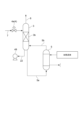
- FIG. 1 is a schematic diagram of a carbon dioxide capture system according to a first embodiment of the present disclosure.
- FIG. FIG. 2 is a schematic diagram illustrating a configuration of a modified example of the carbon dioxide capture system according to the first embodiment of the present disclosure.
- FIG. 2 is a schematic diagram illustrating a configuration of another modified example of the carbon dioxide capture system according to the first embodiment of the present disclosure.
- FIG. 11 is a schematic diagram illustrating the configuration of a carbon dioxide capture system according to a second embodiment of the present disclosure.
- FIG. 11 is a schematic diagram illustrating the configuration of a carbon dioxide capture system according to a third embodiment of the present disclosure.
- FIG. 11 is a schematic diagram illustrating the configuration of a carbon dioxide capture system according to a fourth embodiment of the present disclosure.
- FIG. 11 is a schematic diagram illustrating a configuration of a modified example of the carbon dioxide capture system according to the first, second, and fourth embodiments of the present disclosure.
- the carbon dioxide capture system 1 includes a regenerator 2 that dissipates carbon dioxide from an absorption liquid that has absorbed carbon dioxide, a flash drum 3 that flashes the absorption liquid supplied from the regenerator 2, a pressure reducing valve 4a that is a pressure reducing device 4 that reduces the pressure of the absorption liquid supplied from the regenerator 2 to the flash drum 3, a reboiler 5 that heats the absorption liquid by exchanging heat between the absorption liquid in the flash drum 3 and a heating fluid, and a pressure booster 6 that supplies steam generated in the flash drum 3 to the regenerator 2.
- the pressure reducing valve 4a and the pressure booster 6 are provided in lines 7 and 8 that communicate between the regenerator 2 and the flash drum 3, respectively.
- a compressor 6a can be used as the pressure booster 6.
- the configuration of the reboiler 5 is not particularly limited, but a one-through type, thermosiphon type, or kettle type reboiler can be used.
- the reboiler 5 is illustratively a one-through type reboiler.
- a tray 3a for retaining the absorption liquid that has flowed into the flash drum 3 is provided in the flash drum 3, and a line 5a for supplying the absorption liquid from the flash drum 3 to the reboiler 5 is connected to the flash drum 3 at a position above the tray 3a, and a line 5b for supplying the absorption liquid from the reboiler 5 to the flash drum 3 is connected to the flash drum 3 at a position below the tray 3a.
- the carbon dioxide capture system 1 may include a condenser 10 that condenses water from effluent steam, which is steam flowing out from the regeneration tower 2.
- the condenser 10 may include an effluent steam line 11 having one end connected to the regeneration tower 2, preferably to the top of the regeneration tower 2, a reflux drum 12 connected to the other end of the effluent steam line 11, a condenser 13 provided on the effluent steam line 11, a condensation line 14 that connects the reflux drum 12 and the regeneration tower 2, and a pump 15 provided on the condensation line 14.
- the reflux drum 12 liquid components and gas components mainly composed of carbon dioxide are separated.
- an outlet gas line 16 for discharging the gas components from the reflux drum 12 i.e., from the condensation device 10
- the other end of the outlet gas line 16 may be connected to a device (not shown) for consuming or storing carbon dioxide.
- the outlet gas line 16 may be provided with an outlet gas compressor 17 for pressurizing the outlet gas and a heat exchanger 18 for cooling the outlet gas pressurized by the outlet gas compressor 17. Note that the outlet gas line 16 may be provided with two or more pairs of the outlet gas compressor 17 and the heat exchanger 18.
- a diffusion section 2a is provided, which is configured to be filled with a packing such as Raschig rings.
- a spray 2b is provided for spraying a rich absorption liquid, which is an absorption liquid that has absorbed carbon dioxide, and one end of a rich absorption liquid line 21 through which the rich absorption liquid flows is connected to the spray 2b.
- a lean absorption liquid line 22 is connected to the bottom of the flash drum 3, through which a lean absorption liquid, which is an absorption liquid in which carbon dioxide has been diffused from the rich absorption liquid and has a carbon dioxide content relatively lower than that of the rich absorption liquid, flows out from the flash drum 3.
- the rich absorption liquid supplied to the regeneration tower 2 via the rich absorption liquid line 21 may be one that has been transported to the carbon dioxide capture system 1 after having carbon dioxide absorbed into the absorption liquid at a facility outside the carbon dioxide capture system 1, or a device that absorbs carbon dioxide into the absorption liquid may be provided in the carbon dioxide capture system 1, and the rich absorption liquid may be supplied to the regeneration tower 2 from this device.
- An example of the latter configuration will be described later as a modified example of the first embodiment.
- the rich absorbing liquid that has flowed through the rich absorbing liquid line 21 is sprayed from the spray 2b in the regenerator 2.
- the rich absorbing liquid sprayed in the regenerator 2 falls in the regenerator 2, and in the process, flows down the stripping section 2a.
- the rich absorbing liquid is heated by contact with saturated steam that is generated in an operation described below and rises in the regenerator 2.
- saturated steam that is generated in an operation described below and rises in the regenerator 2.
- the rich absorbing liquid becomes a lean absorbing liquid and accumulates at the bottom of the regenerator 2.
- the lean absorbing liquid in the regenerator 2 is extracted from the bottom of the regenerator 2 and flows through line 7. As the lean absorbing liquid flows through line 7, it is depressurized by pressure reducing valve 4a before flowing into flash drum 3. When the depressurized lean absorbing liquid flows into flash drum 3, the lean absorbing liquid is flashed in flash drum 3. The flash in flash drum 3 causes the carbon dioxide contained in the lean absorbing liquid to dissipate and the water to evaporate. This flash also lowers the temperature of the lean absorbing liquid. As a result, the lean absorbing liquid in flash drum 3 has a lower carbon dioxide content and temperature than the lean absorbing liquid that remains at the bottom of the regenerator 2.
- the lean absorption liquid in the flash drum 3 is retained on the tray 3a, and the lean absorption liquid retained on the tray 3a is continuously supplied to the reboiler 5 via line 5a.
- the lean absorption liquid is heated by heat exchange with a heating fluid, and the heated lean absorption liquid is returned to the flash drum 3 via line 5b.
- the heating in the reboiler 5 also causes carbon dioxide to be emitted from the lean absorption liquid and water to evaporate.
- the lean absorption liquid in the reboiler 5 is a lean absorption liquid whose temperature has been reduced by being flashed in the flash drum 3, the temperature of the heating fluid required in the reboiler 5 can be reduced compared to when the lean absorption liquid supplied from the regeneration tower 2 is heated.
- a heat source having a lower temperature than steam for example, about 80°C
- hot water can be used as the heating fluid used in the reboiler 5
- this heat source can be used directly or via a heat pump.
- saturated steam containing mainly carbon dioxide and water vapor is generated in the flash drum 3.
- This saturated steam is heated by being compressed by the compressor 6a as it flows out from the top of the flash drum 3 and flows through line 8, and flows into the regenerator 2 below the stripping section 2a.
- This saturated steam that flows into the regenerator 2 rises inside the regenerator 2 as described above, and comes into contact with the rich absorption liquid in the stripping section 2a.
- the lean absorbing liquid While the lean absorbing liquid is being supplied from the regenerator 2 to the flash drum 3, the lean absorbing liquid is continuously extracted from the flash drum 3.
- the lean absorbing liquid extracted from the flash drum 3 may be transported to an external facility where the absorbing liquid absorbs carbon dioxide, or may be continuously supplied to an apparatus where the absorbing liquid absorbs carbon dioxide, or may be mixed with the rich absorbing liquid supplied to the regenerator 2 and supplied to the regenerator 2.
- the saturated steam (flowing steam) that flows out of the regenerator 2 is cooled by the condenser 13 as it flows through the flowing steam line 11, and then flows into the reflux drum 12.
- the components with a low boiling point mainly water
- the carbon dioxide remains as a gas. Therefore, in the reflux drum 12, the condensed liquid and the gas are separated into gas and liquid.
- the gas which is mainly carbon dioxide, flows out of the reflux drum 12, i.e., the condensing device 10, as the flowing gas by the flowing gas compressor 17, and is supplied to a device (not shown) for consuming or storing carbon dioxide via the flowing gas line 16.
- the flowing gas is heated when it is pressurized by the flowing gas compressor 17, but if a heat exchanger 18 is provided downstream of the flowing gas compressor 17, it can be cooled in the heat exchanger 18, and the temperature of the flowing gas can be adjusted.
- the temperature of the lean absorption liquid is lowered by flashing the lean absorption liquid in the flash drum 3, and the lean absorption liquid with the lowered temperature is supplied to the reboiler 5, so that the temperature required for the heating fluid supplied to the reboiler 5 can be lowered.
- carbon dioxide can be dissipated from the absorption liquid in the regenerator 2 using a heat source with a lower temperature than steam.
- the amount of heat exchanged in the condenser 13 of the condensing device 10 is also smaller. In other words, the amount of exhaust heat in the condensing device 10 is reduced, so the heat source unit in the carbon dioxide recovery system 1 can be improved.
- the heat exhausted by the carbon dioxide recovery system 1 may be used as a heat source for heating the heating fluid before being supplied to the reboiler 5. That is, at least one heat exchanger may be provided for heating at least a part of the heating fluid by heat exchange between at least a part of the heating fluid and any of the fluid supplied to the carbon dioxide recovery system 1, the fluid in the carbon dioxide recovery system 1, or the fluid flowing out from the carbon dioxide recovery system 1.
- a heat exchanger may be, for example, a condenser 13 (first heat exchanger) that exchanges heat between the heating fluid and the effluent steam flowing out from the regenerator 2.
- such a heat exchanger may be, for example, a heat exchanger 18 (second heat exchanger) that exchanges heat between the heating fluid and the effluent gas pressurized by the effluent gas compressor 17.
- a heat exchanger 18 (second heat exchanger) that exchanges heat between the heating fluid and the effluent gas pressurized by the effluent gas compressor 17.
- any one of the heat exchangers 18 may be used as the second heat exchanger, or the heating fluid may be used so as to pass through at least two heat exchangers 18 in parallel or in series.
- the first and second heat exchangers may be used simultaneously.
- the internal configuration of the flash drum 3 may be a flash drum with nothing provided in the internal space, or a flash drum with a packed bed 3b similar to the stripping section 2a provided in the regenerator 2 provided in the internal space. In the latter case, it has a stripping function of one or more theoretical stages and performs the same function as the stripping section 2a in the regenerator 2, allowing more carbon dioxide to be stripped from the absorption liquid. Note that when a tray 3a is provided in the flash drum 3 (when the reboiler 5 is a one-through type reboiler), the packed bed 3b is provided above the tray 3a.
- the carbon dioxide capture system 1 is equipped with a cooling tower 30 for cooling the gas to be treated that contains at least carbon dioxide, as a device for absorbing carbon dioxide into an absorbing liquid, and an absorption tower 40 for absorbing carbon dioxide into the lean absorbing liquid by bringing the gas to be treated cooled in the cooling tower 30 into gas-liquid contact with the lean absorbing liquid.
- the cooling tower 30 is connected to a gas line 31 through which the gas to be treated flows.
- the gas line 31 may be provided with a heat exchanger 32 for cooling the gas to be treated.
- the cooling tower 30 is provided with a cooling section 30a in which the gas to be treated and the cooling water come into gas-liquid contact to cool the gas to be treated.
- the cooling section 30a may be filled with a filler such as Raschig rings.
- a spray 30b for spraying cooling water is provided, and the cooling water sprayed from the spray 30b is configured to flow down the cooling section 30a.
- the cooling tower 30 is provided with a cooling water circulation line 33, one end of which is connected to the bottom of the cooling tower 30 and the other end of which is connected to the spray 30b.
- the cooling water circulation line 33 is provided with a pump 34 and a heat exchanger 35 for cooling the cooling water.
- the cooling tower 30 and the absorption tower 40 are connected via a line 36.
- the absorption tower 40 is provided with an absorption section 40a that absorbs the carbon dioxide in the gas to be treated that has flowed into the absorption tower 40 after being cooled in the cooling tower 30 into a lean absorption liquid, and a cleaning section 40b that is provided above the absorption section 40a and cleans the gas rising inside the absorption tower 40.
- the absorption section 40a is described as having two stages, a first absorption section 40a1 and a second absorption section 40a2.
- the absorption section 40a may be a one-stage structure or a multi-stage structure of three or more stages.
- the absorption tower 40 is provided with an absorption liquid circulation line 44, one end of which is connected to the space between the first absorption section 40a1 and the second absorption section 40a2.
- the absorption liquid circulation line 44 is provided with a pump 46 and a heat exchanger 45 for cooling the absorption liquid.
- the absorption section 40a and the cleaning section 40b can each be configured to be filled with a packing material, similar to the cooling section 30a in the cooling tower 30.
- a spray 40c is provided for spraying cleaning water, and the cleaning water sprayed from the spray 40c is configured to flow down the cleaning section 40b.
- a tray 40d is provided for retaining the cleaning water that has flowed down the cleaning section 40b.
- the absorption tower 40 is provided with a cleaning water circulation line 41, one end of which communicates with the space between the cleaning section 40b and the tray 40d and the other end of which connects to the spray 40c.
- the cleaning water circulation line 41 is provided with a pump 42 and a heat exchanger 43 for cooling the cleaning water.
- An outflow line 52 is connected to the top of the absorption tower 40, allowing the gas in the absorption tower 40 to flow out of the absorption tower 40.
- the rich absorbent line 21, one end of which is connected to the regeneration tower 2, has the other end connected to the bottom of the absorption tower 40.
- the lean absorbent line 22, one end of which is connected to the flash drum 3, has the other end connected to a spray 53 provided in the space between the absorption section 40a and the cleaning section 40b in the absorption tower 40.
- a heat exchanger 47 is provided for heat exchange between the rich absorbent flowing through the rich absorbent line 21 and the lean absorbent flowing through the lean absorbent line 22.
- the rich absorbent line 21 is provided with a rich absorbent pump 48 between the absorption tower 40 and the heat exchanger 47.
- the lean absorbent line 22 is provided with a lean absorbent pump 49 between the regeneration tower 2 and the heat exchanger 47.
- the lean absorbent line 22 may be provided with heat exchangers 50 and 51 for cooling the lean absorbent between the lean absorbent pump 49 and the heat exchanger 47 and between the heat exchanger 47 and the absorption tower 40, respectively.
- heat exchanger 50 or 51 may be provided.
- the gas to be treated flows into the cooling tower 30 through the gas to be treated line 31. If the gas to be treated line 31 is provided with a heat exchanger 32, the gas to be treated flows into the cooling tower 30 after being cooled in the heat exchanger 32.
- the gas to be treated that flows into the cooling tower 30 rises inside the cooling tower 30.
- the gas to be treated rises inside the cooling section 30a.
- the cooling water sprayed from the spray 30b flows down the cooling section 30a.
- the rising gas to be treated and the flowing cooling water come into gas-liquid contact with each other, so that the gas to be treated is cooled and the cooling water is heated.
- the gas to be treated contains impurities (for example, sulfur oxides, nitrogen oxides, solids such as dust and ash, etc.), the impurities are captured by the cooling water and removed from the gas to be treated.
- impurities for example, sulfur oxides, nitrogen oxides, solids such as dust and ash, etc.
- the cooling water that flows down the cooling section 30a accumulates at the bottom of the cooling tower 30.
- the cooling water that accumulates at the bottom of the cooling tower 30 is extracted from the cooling tower 30 by pump 34 and circulates through the cooling water circulation line 33.
- As the cooling water flows through the cooling water circulation line 33 it is cooled in the heat exchanger 35 and returned to the cooling tower 30.
- the treated gas that has been cooled in the cooling section 30a and from which impurities have been removed flows out of the cooling tower 30, flows through line 36, and enters the absorption tower 40.
- the gas to be treated that flows into the absorption tower 40 rises inside the absorption tower 40.
- the gas to be treated rises inside the absorption section 40a.
- the lean absorbing liquid that flows into the absorption tower 40 via the lean absorbing liquid line 22 is sprayed from the spray 53 and falls inside the absorption tower 40.
- the lean absorbing liquid flows down inside the absorption section 40a.
- the rising gas to be treated and the flowing lean absorbing liquid come into gas-liquid contact, and the carbon dioxide in the gas to be treated is absorbed by the lean absorbing liquid, so that the carbon dioxide is removed from the gas to be treated and the carbon dioxide concentration of the gas to be treated decreases.
- the carbon dioxide content of the lean absorbing liquid increases, turning it into a rich absorbing liquid, which flows out of the absorption section 40a and remains at the bottom of the absorption tower 40.
- the gas to be treated and the lean absorbing liquid come into gas-liquid contact, causing the temperature of the lean absorbing liquid to rise.
- the higher the temperature of the lean absorbing liquid the lower the absorption rate of carbon dioxide. Therefore, a portion of the lean absorbing liquid is extracted from the absorption section 40a by the pump 46, circulated through the absorbing liquid circulation line 44, cooled in the heat exchanger 45, and then returned to the absorption section 40a. This makes it possible to suppress the rise in temperature of the lean absorbing liquid flowing down the absorption section 40a, and therefore the decrease in the absorption rate of carbon dioxide can be suppressed.
- the gas to be treated flowing out from the absorption section 40a rises in the cleaning section 40b. Meanwhile, cleaning water is sprayed from the spray 40c, and the sprayed cleaning water flows down the cleaning section 40b.
- the rising gas to be treated and the flowing down cleaning water come into gas-liquid contact, and the absorbing liquid mist contained in the gas to be treated is recovered by the cleaning water.
- the gas to be treated flowing out from the cleaning section 40b flows out of the absorption tower 40 and flows through the outflow line 52 and is released into the atmosphere. Meanwhile, the cleaning water flowing out from the cleaning section 40b remains on the tray 40d.
- the cleaning water on the tray 40d is extracted from the absorption tower 40 by the pump 42 and flows through the cleaning water circulation line 41.
- the cleaning water is cooled in the heat exchanger 43 as it flows through the cleaning water circulation line 41 and is returned to the absorption tower 40.
- the rich absorbing liquid remaining at the bottom of the absorption tower 40 is extracted from the absorption tower 40 by the rich absorbing liquid pump 48, flows through the rich absorbing liquid line 21, and flows into the regenerator 2.
- the operation of dissipating carbon dioxide from the rich absorbing liquid in the regenerator 2 is the same as in the first embodiment.
- the lean absorbing liquid in the flash drum 3 is extracted from the flash drum 3 by the lean absorbing liquid pump 49, flows through the lean absorbing liquid line 22, and flows into the absorption tower 40.
- the rich absorbing liquid flowing through the rich absorbing liquid line 21 and the lean absorbing liquid flowing through the lean absorbing liquid line 22 exchange heat in the heat exchanger 47, so that the rich absorbing liquid is heated and flows into the regenerator 2, and the lean absorbing liquid is cooled and flows into the absorption tower 40.
- the lean absorbing liquid line 22 is provided with heat exchangers 50 and 51, the lean absorbing liquid is cooled not only in the heat exchanger 47 but also in the heat exchangers 50 and 51.
- the above-mentioned device for absorbing carbon dioxide into the absorbing liquid is equipped with a cooling tower 30 and an absorption tower 40, but the cooling tower 30 is not an essential component, and if the temperature of the gas to be treated is sufficiently low and the concentration of impurities contained in the gas to be treated is also sufficiently low, the cooling tower 30 can be omitted. If the cooling tower 30 is not provided, the gas to be treated line 31 is connected to the absorption tower 40.
- the heating fluid before being supplied to the reboiler 5 can be heated in at least one of the first heat exchanger (condenser 13) or the second heat exchanger (heat exchanger 18).
- the heating fluid can also be heated in another heat exchanger.
- a heat exchanger may be, for example, heat exchanger 32 (third heat exchanger) that exchanges heat between the heating fluid and the gas to be treated.
- heat exchanger 35 fourth heat exchanger
- such a heat exchanger may be, for example, heat exchanger 43 (fifth heat exchanger) that exchanges heat between the heating fluid and the cleaning water extracted from the absorption tower 40.
- heat exchanger may be, for example, heat exchanger 45 (sixth heat exchanger) that exchanges heat between the heating fluid and the absorbing liquid extracted from the absorption section 40a of the absorption tower 40.
- heat exchanger may be, for example, heat exchangers 50, 51 (seventh heat exchanger) that exchange heat between the heating fluid and the lean absorption liquid. This allows the heating fluid to be heated using heat recovered in the carbon dioxide recovery system 1, thereby improving the thermal efficiency of the entire carbon dioxide recovery system 1.
- the heating fluid is not limited to being heated only by any one of the first to seventh heat exchangers, and the heating fluid may be heated by two or more heat exchangers and supplied to the reboiler 5.
- a reclaimer may be provided.
- a branch line 61 branching from the lean absorbing liquid line 22 may be provided, and the downstream end of the branch line 61 may be connected to the reclaimer 60.
- the branch line 61 is depicted as branching from the lean absorbing liquid line 22 downstream of the heat exchanger 47, but it may be branched from the lean absorbing liquid line 22 upstream of the heat exchanger 47.
- a branch line 62 branching from the condensation line 14 downstream of the pump 15 in the condensation device 10 may be provided, and the downstream end of the branch line 62 may be connected to the branch line 61.
- a part of the steam flowing out from the compressor 6a can be used as a heat source for the reclaimer 60.
- a steam supply line 63 may be provided which branches off from the line 8 at the compressor 6a and passes through the reclaimer 60 and is connected to the flash drum 3.
- the absorption liquid in the reclaimer 60 is heated by heat exchange with the steam flowing through the steam supply line 63, thereby generating steam.
- one end of an outflow steam line 64 is connected to the reclaimer 60.
- the other end of the outflow steam line 64 may be connected to the regeneration tower 2, may be connected to the flash drum 3, or may be connected to both the regeneration tower 2 and the flash drum 3.
- the steam generated in the reclaimer 60 i.e., the lean absorption liquid from which non-volatile accumulations have been removed, is supplied to the regeneration tower 2 or the flash drum 3, or both of them, so that the concentration of non-volatile accumulations in the lean absorption liquid can be reduced.
- the condensed water is supplied to the reclaimer 60, where the non-volatile accumulated matter is removed, thereby further reducing the concentration of the non-volatile accumulated matter in the lean absorption liquid.
- the other end of the outflow vapor line 64 may be connected to the lean absorption liquid line 22 downstream of the heat exchanger 47, instead of to the regeneration tower 2 and the flash drum 3.
- a condenser 65 for condensing the vapor must be provided in the outflow vapor line 64.
- the pressure difference causes the vapor to flow from the reclaimer 60 toward the lean absorption liquid line 22.
- the lean absorption liquid from which non-volatile accumulations have been removed is supplied to the absorption tower 40, so that the concentration of non-volatile accumulations in the lean absorption liquid can be reduced.
- the temperature of the heating fluid used as a heat source in the reboiler 5 is low, there may be cases where the heating fluid cannot be used as a heat source for the reclaimer 60 to reduce the concentration of non-volatile accumulations in the lean absorption liquid.
- the heating fluid cannot be used as a heat source for the reclaimer 60 to reduce the concentration of non-volatile accumulations in the lean absorption liquid.
- the steam flowing out from the compressor 6a as a heat source for the reclaimer 60, the concentration of non-volatile accumulations in the lean absorption liquid can be reduced.
- the regeneration tower 2 has a plurality of towers in comparison with embodiment 1.
- the same components as those in embodiment 1 are given the same reference numerals, and detailed description thereof will be omitted.
- the configurations of the respective modified examples described in embodiment 1 can also be applied to embodiment 2.
- the regeneration tower 2 includes a first regeneration tower 70 including two regeneration tower parts 71 and 72 connected in series with each other, and a second regeneration tower 73 connected to the downstream regeneration tower part 72 of the regeneration tower parts 71 and 72. Inside the regeneration tower parts 71 and 72 and the second regeneration tower 73, respectively, are provided with dissipation sections 71a, 72a, and 73a. Inside the second regeneration tower 73, a tray 73b for retaining the absorption liquid that has flowed into the second regeneration tower 73 is provided below the dissipation section 73a.
- the dissipation sections 71a, 72a, and 73a can have the same configuration as the dissipation section 2a of the first embodiment, for example.
- the regeneration tower part 71 is provided with a condensation device 10.
- the configuration of the condensation device 10 is the same as that of the first embodiment.
- the first regeneration tower 70 may include three or more regeneration tower parts, and some of them may be connected in parallel.
- a connecting line 74 is provided to connect the bottom of the regenerator section 71 and the top of the regenerator section 72, and the connecting line 74 may be provided with a pressure reducing valve 76, which is a second pressure reducing device.
- a connecting line 75 is provided to connect the bottom of the regenerator section 72 and the top of the second regenerator 73, and the connecting line 75 is provided with a pressure reducing valve 77, which is a pressure reducing device 4.
- a connecting line 78 is provided to connect the space below the dissipation section 71a in the regenerator section 71 and the space above the dissipation section 72a in the regenerator section 72, and the connecting line 78 is provided with a compressor 80, which is a second boosting device.
- a connecting line 79 is provided to connect the space below the dissipation section 72a in the regenerator section 72 and the space above the dissipation section 73a in the second regenerator 73, and the connecting line 79 is provided with a compressor 81, which is a boosting device 6.
- the second regeneration tower 73 which is part of the regeneration tower 2, performs the function of the flash drum 3 (see FIG. 1) in the first embodiment.
- the reboiler 5 is configured to heat the absorption liquid by exchanging heat between the absorption liquid in the second regeneration tower 73 and a heating fluid, and one end of the lean absorption liquid line 22 is connected to the bottom of the second regeneration tower 73.
- the other configurations are the same as those in the first embodiment.
- the rich absorbing liquid flows into the regenerator section 71 through the rich absorbing liquid line 21.
- the rich absorbing liquid that flows into the regenerator section 71 flows down the stripping section 71a in the same manner as the operation of the rich absorbing liquid in the regenerator 2 (see FIG. 1) in the first embodiment.
- the rich absorbing liquid is heated by contacting with saturated steam rising in the stripping section 71a in an operation to be described later. As a result, at least a part of the carbon dioxide is stripped from the rich absorbing liquid.
- the rich absorbing liquid that flows out from the stripping section 71a has a lower carbon dioxide content than the rich absorbing liquid that flows through the rich absorbing liquid line 21, it will be referred to as the rich absorbing liquid in the second embodiment for convenience of explanation.
- the saturated steam that flows out from the stripping section 71a flows out from the top of the regenerator section 71 and is treated in the condenser 10 by the same operation as in the first embodiment.
- the rich absorbing liquid that flows out of the diffusion section 71a flows out of the regenerator section 71, then flows through the connecting line 74 and flows into the regenerator section 72.
- the rich absorbing liquid that flows into the regenerator section 72 flows down the diffusion section 72a in the same manner as the rich absorbing liquid in the regenerator section 71.
- the rich absorbing liquid flows down the diffusion section 72a, it is heated by contact with saturated steam rising in the diffusion section 72a in the operation described below.
- the rich absorbing liquid becomes lean absorbing liquid and flows out of the diffusion section 72a.
- the absorbing liquid that flows out of the most downstream regenerator section is called lean absorbing liquid.
- the saturated steam that comes into contact with the rich absorbing liquid in the diffusion section 72a and then flows out of the regenerator section 72a is forced out of the regenerator section 72 by the compressor 80, flows through the connecting line 78, and flows into the regenerator section 71.
- the saturated steam that flows into the regenerator section 71 rises in the regenerator section 71, and by the above-mentioned operation, comes into gas-liquid contact with the rich absorbing liquid that has flowed into the regenerator section 71 in the diffusion section 71a.
- a pressure reducing valve 76 is provided in the connecting line 74, the rich absorbing liquid that flows out of the regenerator section 71 flows into the regenerator section 72 in a state where it has been reduced in pressure by the pressure reducing valve 76.
- the rich absorbing liquid is flashed in the regenerator section 72. That is, the regenerator section 72 functions as a flash drum. As a result, the temperature of the rich absorbing liquid that flows out of the regenerator section 71 is lower than when the pressure reducing valve 76 is not provided.
- the lean absorbing liquid flowing out from the diffusion section 72a flows through the connecting line 75 after flowing out from the regenerator section 72, and flows into the second regenerator 73 in a state where it is depressurized by the pressure reducing valve 77.
- the lean absorbing liquid flowing into the second regenerator 73 flows down the diffusion section 73a in the same manner as the rich absorbing liquid in the regenerator sections 71 and 72. While flowing down the diffusion section 73a, the lean absorbing liquid is heated by contact with saturated steam rising in the diffusion section 73a in an operation described below. As a result, carbon dioxide is further diffused from the lean absorbing liquid, and the lean absorbing liquid flows out from the diffusion section 73a and accumulates on the tray 73b.
- the lean absorbing liquid in a state where it is depressurized by the pressure reducing valve 77 flows into the second regenerator 73, so that the lean absorbing liquid is flashed in the second regenerator 73. That is, the second regenerator 73 has the function of a flash drum.
- the lean absorption liquid remaining on the tray 73b in the second regeneration tower 73 is continuously supplied to the reboiler 5 via line 5a.
- the lean absorption liquid is heated by heat exchange with a heating fluid, and the heated lean absorption liquid is returned to the second regeneration tower 73 via line 5b.
- the heating in the reboiler 5 also causes carbon dioxide to be emitted from the lean absorption liquid and water to evaporate.
- the lean absorption liquid in the reboiler 5 is a lean absorption liquid whose temperature has been reduced by being flashed in the second regeneration tower 73, the temperature of the heating fluid required in the reboiler 5 can be reduced compared to when the lean absorption liquid supplied from the regeneration tower portion 72 is heated.
- a heat source having a lower temperature than steam for example, about 80°C
- hot water can be used as the heating fluid used in the reboiler 5, instead of steam, and this heat source can be used directly or via a heat pump.
- saturated steam containing mainly carbon dioxide and water vapor is generated in the second regenerator 73, and this saturated steam rises in the second regenerator 73.
- the saturated steam rises in the diffusion section 73a and comes into contact with the lean absorbing liquid in the above-mentioned operation.
- the saturated steam that comes into contact with the lean absorbing liquid in the diffusion section 73a and then flows out of the diffusion section 73a is forced out of the second regenerator 73 by the compressor 81 and flows into the regenerator section 72 via the connecting line 79.
- the saturated steam that flows into the regenerator section 72 rises in the regenerator section 72 as described above and comes into contact with the rich absorbing liquid in the diffusion section 72a.
- the pressure and temperature in the regeneration tower section 72 are lower than in embodiment 1 having one regeneration tower, and the temperature of the lean absorption liquid is further reduced by flashing the lean absorption liquid in the second regeneration tower 73, which also functions as a flash drum, so that the temperature required for the heating fluid supplied to the reboiler 5 can be further reduced.
- carbon dioxide can be dissipated from the rich absorption liquid and lean absorption liquid in the regeneration tower 2 using a heat source with an even lower temperature.
- the top temperature of the regeneration tower section 71 is lower than in embodiment 1, the amount of heat exchange in the condenser 13 of the condensing device 10 is also smaller. In other words, the amount of exhaust heat in the condensing device 10 is reduced, so the heat source unit in the carbon dioxide recovery system 1 can be improved. Furthermore, since the top pressure of the regeneration tower section 71 can be set higher than in embodiment 1, it is possible to increase the inlet pressure of the outflow gas compressor 17. This makes it possible to reduce the compression ratio of the outflow gas compressor 17, and thus also provides the effect of reducing the power of the outflow gas compressor 17.
- the reboiler 5 is a kettle-type reboiler.
- the lean absorbing liquid is separated into gas and liquid in the reboiler 5, and in order to supply the gas phase resulting from the gas-liquid separation to the flash drum 3, the reboiler 5 and the flash drum 3 are communicated via a gas phase supply line 90.
- one end of a lean absorbing liquid line 22 is connected to the reboiler 5.
- the other configurations are the same as those in the first embodiment.
- the operation of the third embodiment is the same as that of the first embodiment, except for the operation in the reboiler 5. Therefore, only the operation in the reboiler 5 will be described below.
- the lean absorbing liquid is in a gas-liquid equilibrium state inside the reboiler 5. That is, in the reboiler 5, not only the heating of the lean absorbing liquid but also the gas-liquid separation of the lean absorbing liquid is performed, and the reboiler 5 functions as one theoretical stage in the regeneration of the absorbing liquid.
- the gas phase resulting from the gas-liquid separation is supplied to the flash drum 3 via the gas phase supply line 90, and the liquid phase resulting from the gas-liquid separation flows out of the reboiler 5 via the lean absorbing liquid line 22.
- the kettle-type reboiler 5 not only the heating of the lean absorbing liquid but also the gas-liquid separation of the lean absorbing liquid is performed, so that the dissipation of carbon dioxide from the lean absorbing liquid in the flash drum 3 can be promoted.
- the carbon dioxide capture system according to the fourth embodiment is configured to use a steam ejector as the pressure booster 6 in each of the first to third embodiments.
- the third embodiment will be described in a configuration in which a steam ejector is used as the pressure booster 6 in the first embodiment, but the fourth embodiment may be configured by using a steam ejector as the pressure booster 6 in each of the second and third embodiments.
- the same components as those in the first embodiment are given the same reference numerals, and detailed description thereof will be omitted.
- the configurations of the modifications described in the first embodiment can also be applied to the fourth embodiment.
- the booster 6 is a steam ejector 6b.
- One end of a steam supply line 91 for supplying driving steam as a driving source to the steam ejector 6b is connected to the steam ejector 6b.
- the other configurations are the same as those of the first embodiment.
- the operation of the fourth embodiment is the same as that of the first embodiment, except for the operation of supplying saturated steam from the flash drum 3 to the regenerator 2. Therefore, only the operation of supplying saturated steam from the flash drum 3 to the regenerator 2 will be described below.
- the saturated steam flowing out from the flash drum 3 flows through the line 8.
- the motive steam is supplied to the steam ejector 6b through the steam supply line 91.
- the motive steam is injected at high speed from a nozzle (not shown) of the steam ejector 6b, generating a low-pressure space in the steam ejector 6b, and the saturated steam is sucked into the steam ejector 6b through the line 8.
- the motive steam moves toward the outlet while entraining and mixing with the saturated steam, and the mixed steam of the motive steam and the saturated steam is discharged from the outlet while reducing its speed in a diffuser (not shown) of the steam ejector 6b.
- the mixed steam discharged from the steam ejector 6b flows into the regenerator 2.
- the supply source of the motive steam is not specified, but any steam can be used.
- the steam supply line 91 may be provided with a motive steam generator 92, which exchanges heat between a heat source and water flowing through the steam supply line 91 to heat water to generate motive steam, and the motive steam may be supplied to the steam ejector 6b.
- the motive steam is supplied to the regenerator 2 together with the saturated steam, so that water needs to be extracted from the regenerator 2 to maintain the water balance in the regenerator 2.
- the other end of the steam supply line 91 may be connected to the condensation line 14 between the pump 15 and the regenerator 2, i.e., the steam supply line 91 may be branched off from the condensation line 14 downstream of the pump 15, and the motive steam may be generated by heating the water condensed in the condenser 10 in the motive steam generator 92.
- the heat source used to generate the motive steam in the motive steam generating device 92 may be any fluid.
- the motive steam generating device 92 may be, for example, a heat exchanger 18 (8th heat exchanger) that exchanges heat between the effluent gas pressurized by the effluent gas compressor 17 and the water condensed in the condensing device 10. If two or more pairs of the effluent gas compressor 17 and the heat exchanger 18 are provided, any one of the heat exchangers 18 may be used as the 8th heat exchanger, or the heating fluid may pass through at least two heat exchangers 18 in parallel or in series.
- the motive steam generating device 92 may also be, for example, a heat exchanger 32 (9th heat exchanger) that exchanges heat between the gas to be treated supplied to the cooling tower 30 (see FIG. 2) and the water condensed in the condensing device 10.
- the motive steam generating device 92 may be, for example, a heat exchanger 35 (tenth heat exchanger) that exchanges heat between the cooling water after cooling the gas to be treated in the cooling tower 30 and the water condensed in the condensing device 10.
- any two or all of the eighth, ninth, and tenth heat exchangers may be used simultaneously.
- the heat recovered in the carbon dioxide recovery system 1 is used to generate the motive steam to be supplied to the steam ejector 6b, so that the thermal efficiency of the entire carbon dioxide recovery system 1 can be improved.
- the reboiler 5 in the first and fourth embodiments and the second regenerator 73 in the second embodiment are each illustratively a one-through type reboiler, but the configuration of a thermosiphon type reboiler 5 is shown in Fig. 7. No tray 3a (see Fig. 1, etc.) is provided inside the flash drum 3, and the line 5a is connected to the bottom of the flash drum 3.
- the other configurations are the same as those of a one-through type reboiler.
- thermosiphon type reboiler 5 The operation of the thermosiphon type reboiler 5 is the same as that of the one-through type reboiler, except that the reduced pressure lean absorption liquid flowing into the flash drum 3 via line 7 and the lean absorption liquid returned to the flash drum 3 after being heated in the reboiler 5 are mixed at the bottom of the flash drum 3.
- a carbon dioxide capture system comprises: A regeneration tower (2) that releases carbon dioxide from the absorption liquid that has absorbed carbon dioxide; a flash drum (3) for flashing the absorption liquid supplied from the regeneration tower (2); a pressure reducing device (4) for reducing the pressure of the absorption liquid supplied from the regeneration tower (2) to the flash drum (3); a reboiler (5) for heating the absorption liquid by heat exchange between the absorption liquid in the flash drum (3) and a heating fluid; and a pressure booster (6) that supplies the steam generated in the flash drum (3) to the regeneration tower (2).
- the temperature of the absorbing liquid is lowered by flashing the absorbing liquid in the flash drum, and the lowered-temperature absorbing liquid is supplied to the reboiler, so the temperature required for the heating fluid supplied to the reboiler can be lowered.
- carbon dioxide can be dissipated from the absorbing liquid in the regenerator using a heat source with a lower temperature than steam.
- a carbon dioxide capture system is the carbon dioxide capture system of [1]
- the regeneration tower (2) comprises at least two regeneration tower sections (71, 72),
- the pressure reducing device (4) is configured to reduce the pressure of the absorption liquid supplied from the most downstream regeneration tower section (72) of the at least two regeneration tower sections (71, 72) to the flash drum (second regeneration tower 73).
- a carbon dioxide capture system is the carbon dioxide capture system according to [2], a second pressure reducing device (pressure reducing valve 76) for reducing the pressure of the absorption liquid supplied from the upstream regenerator section (71) to the downstream regenerator section (72) in two of the at least two regenerator sections (71, 72) that are directly connected to each other; and a second booster (compressor 80) that supplies steam in the downstream regenerator section (72) to the upstream regenerator section (71).
- a second pressure reducing device pressure reducing valve 76 for reducing the pressure of the absorption liquid supplied from the upstream regenerator section (71) to the downstream regenerator section (72) in two of the at least two regenerator sections (71, 72) that are directly connected to each other
- a second booster compressor 80
- the absorption liquid can be flashed in the downstream regeneration tower. This further reduces the temperature of the absorption liquid flashed in the flash drum, making it possible to further reduce the temperature required for the heating fluid supplied to the reboiler. As a result, it is possible to dissipate carbon dioxide from the absorption liquid in the regeneration tower using a heat source with an even lower temperature than that of [2] above.
- a carbon dioxide capture system is any one of the carbon dioxide capture systems according to [1] to [3],
- the reboiler (5) is a kettle type reboiler.
- a carbon dioxide capture system is any of the carbon dioxide capture systems according to [1] to [4], at least one heat exchanger that heats at least a portion of the heating fluid by heat exchange between at least a portion of the heating fluid and any one of a fluid supplied to the carbon dioxide capture system (1), a fluid in the carbon dioxide capture system (1), or a fluid flowing out of the carbon dioxide capture system (1);
- the heating fluid heated in the at least one heat exchanger is configured to be supplied to the reboiler (5).
- the heat recovered within the carbon dioxide capture system is used to heat the heating fluid, improving the thermal efficiency of the entire carbon dioxide capture system.
- a carbon dioxide capture system is any of the carbon dioxide capture systems according to [1] to [5],
- the pressure boosting device (6) is a steam ejector (6b) that boosts the pressure of the steam generated in the flash drum (3) by using motive steam.
- a carbon dioxide capture system is the carbon dioxide capture system according to [6], a condensation device (10) for condensing water from the effluent steam flowing out from the regeneration tower (2); and at least one motive steam generator (92) that generates at least a portion of the motive steam by heating the water condensed in the condenser (10).
- the heat recovered within the carbon dioxide capture system is used to generate driving steam to be supplied to the steam ejector, thereby improving the thermal efficiency of the entire carbon dioxide capture system.
- a carbon dioxide capture system is any of the carbon dioxide capture systems according to [1] to [7],
- An absorption tower (40) that absorbs carbon dioxide into the absorbing liquid by bringing a gas to be treated that contains at least carbon dioxide into gas-liquid contact with the absorbing liquid, and the absorbing liquid that has absorbed carbon dioxide is supplied to the regeneration tower (2); a reclaimer (60) that generates steam of the absorbing liquid by heat exchange between steam flowing out from a compressor (6a) that is the boosting device (6) and a part of the absorbing liquid flowing out from the flash drum (3),
- the vapor of the absorbing liquid is configured to be supplied to the absorber (40) or to at least one of the regenerator (2) or the flash drum (3).
- the steam flowing out from the compressor can be used as a heat source for the reclaimer.
- a carbon dioxide capture system is the carbon dioxide capture system according to [8]
- a condensation device (10) is provided for condensing water from the effluent steam flowing out from the regeneration tower (2)
- the reclaimer (60) is configured to generate steam of the absorption liquid by heat exchange between steam flowing out from the compressor (6a) which is the boosting device (6) and a portion of the absorption liquid flowing out from the flash drum (3) and a portion of the water condensed in the condenser (10).
Landscapes
- Chemical & Material Sciences (AREA)
- Chemical Kinetics & Catalysis (AREA)
- Engineering & Computer Science (AREA)
- Analytical Chemistry (AREA)
- General Chemical & Material Sciences (AREA)
- Oil, Petroleum & Natural Gas (AREA)
- Health & Medical Sciences (AREA)
- Biomedical Technology (AREA)
- Environmental & Geological Engineering (AREA)
- Treating Waste Gases (AREA)
- Gas Separation By Absorption (AREA)
Abstract
Description
<本開示の実施形態1に係る二酸化炭素回収システムの構成>
図1に示されるように、本開示の実施形態1に係る二酸化炭素回収システム1は、二酸化炭素を吸収した吸収液から二酸化炭素を放散させる再生塔2と、再生塔2から供給された吸収液をフラッシュさせるフラッシュドラム3と、再生塔2からフラッシュドラム3へ供給される吸収液を減圧する減圧装置4である減圧弁4aと、フラッシュドラム3内の吸収液と加熱流体とを熱交換することにより吸収液を加熱するリボイラ5と、フラッシュドラム3で発生した蒸気を再生塔2に供給する昇圧装置6とを備えている。減圧弁4a及び昇圧装置6はそれぞれ、再生塔2とフラッシュドラム3とを連通するライン7及び8に設けられている。昇圧装置6として例えばコンプレッサ6aを使用できる。
次に、本開示の実施形態1に係る二酸化炭素回収システム1の動作について説明する。リッチ吸収液ライン21を流通したリッチ吸収液は、スプレイ2bから再生塔2内で散布される。再生塔2内で散布されたリッチ吸収液は、再生塔2内を落下し、この過程で放散部2aを流下する。リッチ吸収液は、放散部2aを流下する際に、後述する動作で生成して再生塔2内を上昇する飽和蒸気と接触することにより加熱される。これにより、リッチ吸収液から二酸化炭素の少なくとも一部が放散され、リッチ吸収液はリーン吸収液となって、再生塔2の塔底に滞留する。
実施形態1では、リボイラ5に供給される前の加熱流体を加熱するための熱源として、二酸化炭素回収システム1で排熱される熱を使用してもよい。すなわち、二酸化炭素回収システム1に供給される流体、二酸化炭素回収システム1内の流体、又は二酸化炭素回収システム1から流出する流体のいずれかと加熱流体の少なくとも一部とが熱交換することにより加熱流体の少なくとも一部を加熱する少なくとも1つの熱交換器を設けてもよい。このような熱交換器は、例えば、加熱流体と再生塔2から流出した流出蒸気とを熱交換するコンデンサ13(第1熱交換器)であってもよい。また、このような熱交換器は、例えば、加熱流体と流出ガスコンプレッサ17によって昇圧された流出ガスとを熱交換する熱交換器18(第2熱交換器)であってもよい。尚、流出ガスコンプレッサ17及び熱交換器18の組が2組以上設けられている場合は、第2熱交換器としていずれか1つの熱交換器18を使用してもよいし、加熱流体が少なくとも2つの熱交換器18のそれぞれを並列に又は直列に通過するように使用してもよい。さらに、第1熱交換器及び第2熱交換器を同時に使用してもよい。
次に、実施形態2に係る二酸化炭素回収システムについて説明する。実施形態2に係る二酸化炭素回収システムは、実施形態1に対して、再生塔2が複数の塔を有するようにしたものである。尚、実施形態2において、実施形態1の構成要件と同じものは同じ参照符号を付し、その詳細な説明は省略する。また、構成上の矛盾がない限り、実施形態1で説明した各変形例の構成を実施形態2にも適用可能である。
図4に示されるように、実施形態2に係る二酸化炭素回収システム1では、再生塔2は、互いに直列に連結された2つの再生塔部分71,72を含む第1再生塔70と、再生塔部分71,72のうち下流側の再生塔部分72に連結される第2再生塔73とを備えている。再生塔部分71,72及び第2再生塔73の内部にはそれぞれ、放散部71a,72a,73aが設けられている。第2再生塔73の内部には放散部73aよりも下方に、第2再生塔73に流入した吸収液を滞留させるトレイ73bが設けられている。放散部71a,72a,73aは例えば、実施形態1の放散部2aと同じ構成を有することができる。再生塔部分71には凝縮装置10が設けられている。凝縮装置10の構成は実施形態1と同じである。尚、第1再生塔70は3つ以上の再生塔部分を備えてもよいし、それらのうちのいくつかが並列に連結されてもよい。
次に、本開示の実施形態2に係る二酸化炭素回収システム1の動作について説明する。リッチ吸収液ライン21を介してリッチ吸収液が再生塔部分71に流入する。再生塔部分71に流入したリッチ吸収液は、実施形態1における再生塔2(図1参照)内でのリッチ吸収液の動作と同様に、放散部71aを流下する。リッチ吸収液は、放散部71aを流下する間に、後述する動作で放散部71a内を上昇する飽和蒸気と接触することにより加熱される。これにより、リッチ吸収液から二酸化炭素の少なくとも一部が放散される。尚、放散部71aから流出したリッチ吸収液は、リッチ吸収液ライン21を流通するリッチ吸収液よりも二酸化炭素含有率は低いものの、実施形態2では説明の便宜上、リッチ吸収液と呼ぶこととする。一方、放散部71aから流出した飽和蒸気は、再生塔部分71の塔頂から流出し、凝縮装置10において実施形態1と同じ動作によって処理される。
次に、実施形態3に係る二酸化炭素回収システムについて説明する。実施形態3に係る二酸化炭素回収システムは、実施形態1又は2に対して、リボイラ5をケトル型のリボイラに変更したものである。以下の説明では、実施形態1に対してリボイラ5をケトル型のリボイラに変更した構成で実施形態3を説明するが、実施形態2に対してリボイラ5をケトル型のリボイラに変更することにより実施形態3を構成してもよい。尚、実施形態3において、実施形態1の構成要件と同じものは同じ参照符号を付し、その詳細な説明は省略する。また、構成上の矛盾がない限り、実施形態1で説明した各変形例の構成を実施形態3にも適用可能である。
図5に示されるように、実施形態3に係る二酸化炭素回収システム1では、リボイラ5はケトル型のリボイラである。後述するように、リボイラ5内ではリーン吸収液が気液分離されるが、気液分離された気相をフラッシュドラム3に供給するために、気相供給ライン90を介してリボイラ5とフラッシュドラム3とが連通されている。気液分離された液相をリボイラ5から流出させるために、リーン吸収液ライン22の一端がリボイラ5に接続されている。その他の構成は実施形態1と同じである。
実施形態3の動作は、リボイラ5における動作を除き、実施形態1の動作と同じである。従って、以下では、リボイラ5における動作についてのみ説明する。ケトル型のリボイラ5では、リボイラ5の内部でリーン吸収液が気液平衡状態となる。すなわち、リボイラ5内では、リーン吸収液の加熱だけではなく、リーン吸収液の気液分離も行われ、リボイラ5が吸収液の再生における理論段1段分の機能を果たすことになる。実施形態3では、気液分離された気相が気相供給ライン90を介してフラッシュドラム3に供給され、気液分離された液相はリーン吸収液ライン22を介してリボイラ5から流出する。このように、ケトル型のリボイラ5を用いることにより、リーン吸収液の加熱だけではなくリーン吸収液の気液分離も行われるので、フラッシュドラム3におけるリーン吸収液からの二酸化炭素の放散を促進することができる。
次に、実施形態4に係る二酸化炭素回収システムについて説明する。実施形態4に係る二酸化炭素回収システムは、実施形態1~3のそれぞれに対して、昇圧装置6としてスチームエジェクタを用いるようにしたものである。以下の説明では、実施形態1に対して昇圧装置6としてスチームエジェクタを用いた構成で実施形態3を説明するが、実施形態2及び3のそれぞれに対して昇圧装置6としてスチームエジェクタを用いることにより実施形態4を構成してもよい。尚、実施形態4において、実施形態1の構成要件と同じものは同じ参照符号を付し、その詳細な説明は省略する。また、構成上の矛盾がない限り、実施形態1で説明した各変形例の構成を実施形態4にも適用可能である。
図6に示されるように、実施形態4に係る二酸化炭素回収システム1では、昇圧装置6はスチームエジェクタ6bである。スチームエジェクタ6bには、スチームエジェクタ6bに駆動源としての駆動蒸気を供給するための蒸気供給ライン91の一端が接続されている。その他の構成は実施形態1と同じである。
実施形態4の動作は、フラッシュドラム3から再生塔2へ飽和蒸気を供給する動作を除き、実施形態1の動作と同じである。従って、以下では、フラッシュドラム3から再生塔2へ飽和蒸気を供給する動作についてのみ説明する。フラッシュドラム3から流出した飽和蒸気はライン8を流通する。スチームエジェクタ6bには、蒸気供給ライン91を介して駆動蒸気が供給される。スチームエジェクタ6bの図示しないノズルにより駆動蒸気が高速噴射されることで、スチームエジェクタ6b内に低圧空間が生成され、飽和蒸気がライン8を介してスチームエジェクタ6bに吸引される。スチームエジェクタ6b内では、駆動蒸気は飽和蒸気を同伴混合しながら出口に向かい、駆動蒸気と飽和蒸気との混合蒸気がスチームエジェクタ6bの図示しないディフューザー部において速度を減じながら出口から吐出される。スチームエジェクタ6bから吐出された混合蒸気は、再生塔2に流入する。
実施形態4では、駆動蒸気の供給源を特定していないが、任意の蒸気を使用できる。蒸気供給ライン91には、駆動蒸気生成装置92を設け、駆動蒸気生成装置92において熱源と蒸気供給ライン91を流通する水とを熱交換することにより水を加熱して駆動蒸気を生成し、この駆動蒸気をスチームエジェクタ6bに供給してもよい。また、実施形態4では再生塔2に飽和蒸気と共に駆動蒸気も供給されるので、再生塔2の水バランスを維持するために再生塔2から水の抜き出しを行う必要がある。そこで、蒸気供給ライン91の他端をポンプ15と再生塔2との間で凝縮ライン14に接続し、すなわち、ポンプ15の下流で凝縮ライン14から蒸気供給ライン91を分岐させるようにして、凝縮装置10で凝縮された水を駆動蒸気生成装置92において加熱することにより駆動蒸気を生成するようにしてもよい。
実施形態1及び4のリボイラ5並びに実施形態2の第2再生塔73はそれぞれ、例示的にワンスルー型のリボイラであったが、サーモサイフォン型のリボイラ5である場合の構成を図7に示す。フラッシュドラム3の内部には、トレイ3a(図1等参照)が設けられておらず、ライン5aはフラッシュドラム3の塔底に接続されている。その他の構成はワンスルー型のリボイラの構成と同じである。
二酸化炭素を吸収した吸収液から二酸化炭素を放散させる再生塔(2)と、
前記再生塔(2)から供給された前記吸収液をフラッシュさせるフラッシュドラム(3)と、
前記再生塔(2)から前記フラッシュドラム(3)へ供給される前記吸収液を減圧する減圧装置(4)と、
前記フラッシュドラム(3)内の前記吸収液と加熱流体とを熱交換することにより前記吸収液を加熱するリボイラ(5)と、
前記フラッシュドラム(3)で発生した蒸気を前記再生塔(2)に供給する昇圧装置(6)と
を備える。
前記再生塔(2)は少なくとも2つの再生塔部分(71,72)を含み、
前記減圧装置(4)は、前記少なくとも2つの再生塔部分(71,72)のうち最も下流側の再生塔部分(72)から前記フラッシュドラム(第2再生塔73)へ供給される前記吸収液を減圧するように構成されている。
前記少なくとも2つの再生塔部分(71,72)のうち、互いに直接連結される2つの再生塔部分(71,72)において、上流側の再生塔部分(71)から下流側の再生塔部分(72)へ供給される前記吸収液を減圧する第2減圧装置(減圧弁76)と、
前記下流側の再生塔部分(72)内の蒸気を前記上流側の再生塔部分(71)に供給する第2昇圧装置(コンプレッサ80)と
を備える。
前記リボイラ(5)はケトル型のリボイラである。
前記二酸化炭素回収システム(1)に供給される流体、前記二酸化炭素回収システム(1)内の流体、又は前記二酸化炭素回収システム(1)から流出する流体のいずれかと前記加熱流体の少なくとも一部とが熱交換することにより前記加熱流体の少なくとも一部を加熱する少なくとも1つの熱交換器を備え、
前記少なくとも1つの熱交換器において加熱された前記加熱流体が前記リボイラ(5)に供給されるように構成されている。
前記昇圧装置(6)は、前記フラッシュドラム(3)で発生した前記蒸気を駆動蒸気により昇圧するスチームエジェクタ(6b)である。
前記再生塔(2)から流出した流出蒸気から水を凝縮させる凝縮装置(10)と、
前記凝縮装置(10)において凝縮した前記水を加熱することにより前記駆動蒸気の少なくとも一部を生成する少なくとも1つの駆動蒸気生成装置(92)と
を備える。
少なくとも二酸化炭素を含む被処理ガスと前記吸収液とを気液接触させることにより二酸化炭素を前記吸収液に吸収させる吸収塔(40)であって、二酸化炭素を吸収した前記吸収液が前記再生塔(2)に供給されるように構成されている吸収塔(40)と、
前記昇圧装置(6)であるコンプレッサ(6a)から流出した蒸気と、前記フラッシュドラム(3)から流出した前記吸収液の一部とを熱交換することにより前記吸収液の蒸気を発生させるリクレーマ(60)と
を備え、
前記吸収液の前記蒸気は、前記吸収塔(40)に、若しくは、前記再生塔(2)又は前記フラッシュドラム(3)の少なくとも一方に供給されるように構成されている。
前記再生塔(2)から流出した流出蒸気から水を凝縮させる凝縮装置(10)を備え、
前記リクレーマ(60)は、前記昇圧装置(6)であるコンプレッサ(6a)から流出した蒸気と、前記フラッシュドラム(3)から流出した前記吸収液の一部及び前記凝縮装置(10)において凝縮した前記水の一部とを熱交換することにより前記吸収液の蒸気を発生させるように構成されている。
2 再生塔
3 フラッシュドラム
4 減圧装置
5 リボイラ
6 昇圧装置
6a コンプレッサ
6b スチームエジェクタ
10 凝縮装置
13 コンデンサ(熱交換器)
17 流出ガスコンプレッサ
18 熱交換器
30 冷却塔
32 熱交換器
35 熱交換器
40 吸収塔
43 熱交換器
45 熱交換器
50 熱交換器
51 熱交換器
60 リクレーマ
71 再生塔部分
72 再生塔部分
73 第2再生塔(フラッシュドラム)
76 減圧弁(第2減圧装置)
77 減圧弁(減圧装置)
80 コンプレッサ(第2昇圧装置)
81 コンプレッサ(昇圧装置)
92 駆動蒸気生成装置
Claims (9)
- 二酸化炭素を吸収した吸収液から二酸化炭素を放散させる再生塔と、
前記再生塔から供給された前記吸収液をフラッシュさせるフラッシュドラムと、
前記再生塔から前記フラッシュドラムへ供給される前記吸収液を減圧する減圧装置と、
前記フラッシュドラム内の前記吸収液と加熱流体とを熱交換することにより前記吸収液を加熱するリボイラと、
前記フラッシュドラムで発生した蒸気を前記再生塔に供給する昇圧装置と
を備える二酸化炭素回収システム。 - 前記再生塔は少なくとも2つの再生塔部分を含み、
前記減圧装置は、前記少なくとも2つの再生塔部分のうち最も下流側の再生塔部分から前記フラッシュドラムへ供給される前記吸収液を減圧するように構成されている、請求項1に記載の二酸化炭素回収システム。 - 前記少なくとも2つの再生塔部分のうち、互いに直接連結される2つの再生塔部分において、上流側の再生塔部分から下流側の再生塔部分へ供給される前記吸収液を減圧する第2減圧装置と、
前記下流側の再生塔部分内の蒸気を前記上流側の再生塔部分に供給する第2昇圧装置と
を備える、請求項2に記載の二酸化炭素回収システム。 - 前記リボイラはケトル型のリボイラである、請求項1~3のいずれか一項に記載の二酸化炭素回収システム。
- 前記二酸化炭素回収システムに供給される流体、前記二酸化炭素回収システム内の流体、又は前記二酸化炭素回収システムから流出する流体のいずれかと前記加熱流体の少なくとも一部とが熱交換することにより前記加熱流体の少なくとも一部を加熱する少なくとも1つの熱交換器を備え、
前記少なくとも1つの熱交換器において加熱された前記加熱流体が前記リボイラに供給されるように構成されている、請求項1~3のいずれか一項に記載の二酸化炭素回収システム。 - 前記昇圧装置は、前記フラッシュドラムで発生した前記蒸気を駆動蒸気により昇圧するスチームエジェクタである、請求項1~3のいずれか一項に記載の二酸化炭素回収システム。
- 前記再生塔から流出した流出蒸気から水を凝縮させる凝縮装置と、
前記凝縮装置において凝縮した前記水を加熱することにより前記駆動蒸気の少なくとも一部を生成する少なくとも1つの駆動蒸気生成装置と
を備える、請求項6に記載の二酸化炭素回収システム。 - 少なくとも二酸化炭素を含む被処理ガスと前記吸収液とを気液接触させることにより二酸化炭素を前記吸収液に吸収させる吸収塔であって、二酸化炭素を吸収した前記吸収液が前記再生塔に供給されるように構成されている吸収塔と、
前記昇圧装置であるコンプレッサから流出した蒸気と、前記フラッシュドラムから流出した前記吸収液の一部とを熱交換することにより前記吸収液の蒸気を発生させるリクレーマと
を備え、
前記吸収液の前記蒸気は、前記吸収塔に、若しくは、前記再生塔又は前記フラッシュドラムの少なくとも一方に供給されるように構成されている、請求項1~3のいずれか一項に記載の二酸化炭素回収システム。 - 前記再生塔から流出した流出蒸気から水を凝縮させる凝縮装置を備え、
前記リクレーマは、前記昇圧装置であるコンプレッサから流出した蒸気と、前記フラッシュドラムから流出した前記吸収液の一部及び前記凝縮装置において凝縮した前記水の一部とを熱交換することにより前記吸収液の蒸気を発生させるように構成されている、請求項8に記載の二酸化炭素回収システム。
Priority Applications (4)
| Application Number | Priority Date | Filing Date | Title |
|---|---|---|---|
| JP2025509497A JPWO2024201895A1 (ja) | 2023-03-30 | 2023-03-30 | |
| AU2023439926A AU2023439926A1 (en) | 2023-03-30 | 2023-03-30 | Carbon dioxide recovery system |
| PCT/JP2023/013191 WO2024201895A1 (ja) | 2023-03-30 | 2023-03-30 | 二酸化炭素回収システム |
| EP23930533.7A EP4670823A4 (en) | 2023-03-30 | 2023-03-30 | CARBON DIOXIDE RECOVERY SYSTEM |
Applications Claiming Priority (1)
| Application Number | Priority Date | Filing Date | Title |
|---|---|---|---|
| PCT/JP2023/013191 WO2024201895A1 (ja) | 2023-03-30 | 2023-03-30 | 二酸化炭素回収システム |
Publications (1)
| Publication Number | Publication Date |
|---|---|
| WO2024201895A1 true WO2024201895A1 (ja) | 2024-10-03 |
Family
ID=92904345
Family Applications (1)
| Application Number | Title | Priority Date | Filing Date |
|---|---|---|---|
| PCT/JP2023/013191 Ceased WO2024201895A1 (ja) | 2023-03-30 | 2023-03-30 | 二酸化炭素回収システム |
Country Status (4)
| Country | Link |
|---|---|
| EP (1) | EP4670823A4 (ja) |
| JP (1) | JPWO2024201895A1 (ja) |
| AU (1) | AU2023439926A1 (ja) |
| WO (1) | WO2024201895A1 (ja) |
Citations (11)
| Publication number | Priority date | Publication date | Assignee | Title |
|---|---|---|---|---|
| JPS62143809A (ja) * | 1985-12-17 | 1987-06-27 | Nippon Steel Corp | 一酸化炭素分離装置の運転制御方法 |
| JPH1067994A (ja) * | 1996-08-28 | 1998-03-10 | Mitsubishi Heavy Ind Ltd | 高圧原料ガス中の二酸化炭素の高度除去及び高圧回収方法並びにその装置 |
| JP2006036950A (ja) * | 2004-07-28 | 2006-02-09 | Mitsubishi Materials Corp | ガスを精製する方法及びその精製に用いられる吸収液 |
| JP2010120013A (ja) * | 2008-10-23 | 2010-06-03 | Hitachi Ltd | 二酸化炭素と硫化水素の除去方法および除去装置 |
| JP2011068751A (ja) * | 2009-09-25 | 2011-04-07 | Hitachi Ltd | 原料ガスの脱炭酸脱硫方法および脱炭酸脱硫装置 |
| WO2012073553A1 (ja) | 2010-12-01 | 2012-06-07 | 三菱重工業株式会社 | Co2回収システム |
| JP2012162424A (ja) * | 2011-02-08 | 2012-08-30 | Hitachi Ltd | Co2回収方法およびco2回収装置 |
| WO2012176430A1 (ja) * | 2011-06-20 | 2012-12-27 | バブコック日立株式会社 | 燃焼排ガス処理システムおよび燃焼排ガス処理方法 |
| WO2014013939A1 (ja) * | 2012-07-20 | 2014-01-23 | 三菱重工業株式会社 | Co2回収システム |
| WO2014098154A1 (ja) * | 2012-12-20 | 2014-06-26 | バブコック日立株式会社 | 二酸化炭素の回収装置、及び該回収装置の運転方法 |
| JP2015024398A (ja) * | 2013-07-29 | 2015-02-05 | 株式会社東芝 | 二酸化炭素分離回収システム及びその運転方法 |
Family Cites Families (1)
| Publication number | Priority date | Publication date | Assignee | Title |
|---|---|---|---|---|
| JP5737916B2 (ja) * | 2010-12-01 | 2015-06-17 | 三菱重工業株式会社 | Co2回収システム |
-
2023
- 2023-03-30 EP EP23930533.7A patent/EP4670823A4/en active Pending
- 2023-03-30 JP JP2025509497A patent/JPWO2024201895A1/ja active Pending
- 2023-03-30 WO PCT/JP2023/013191 patent/WO2024201895A1/ja not_active Ceased
- 2023-03-30 AU AU2023439926A patent/AU2023439926A1/en active Pending
Patent Citations (12)
| Publication number | Priority date | Publication date | Assignee | Title |
|---|---|---|---|---|
| JPS62143809A (ja) * | 1985-12-17 | 1987-06-27 | Nippon Steel Corp | 一酸化炭素分離装置の運転制御方法 |
| JPH1067994A (ja) * | 1996-08-28 | 1998-03-10 | Mitsubishi Heavy Ind Ltd | 高圧原料ガス中の二酸化炭素の高度除去及び高圧回収方法並びにその装置 |
| JP2006036950A (ja) * | 2004-07-28 | 2006-02-09 | Mitsubishi Materials Corp | ガスを精製する方法及びその精製に用いられる吸収液 |
| JP2010120013A (ja) * | 2008-10-23 | 2010-06-03 | Hitachi Ltd | 二酸化炭素と硫化水素の除去方法および除去装置 |
| JP2011068751A (ja) * | 2009-09-25 | 2011-04-07 | Hitachi Ltd | 原料ガスの脱炭酸脱硫方法および脱炭酸脱硫装置 |
| WO2012073553A1 (ja) | 2010-12-01 | 2012-06-07 | 三菱重工業株式会社 | Co2回収システム |
| JP2012162424A (ja) * | 2011-02-08 | 2012-08-30 | Hitachi Ltd | Co2回収方法およびco2回収装置 |
| WO2012176430A1 (ja) * | 2011-06-20 | 2012-12-27 | バブコック日立株式会社 | 燃焼排ガス処理システムおよび燃焼排ガス処理方法 |
| JP2013000694A (ja) * | 2011-06-20 | 2013-01-07 | Babcock Hitachi Kk | Co2回収設備 |
| WO2014013939A1 (ja) * | 2012-07-20 | 2014-01-23 | 三菱重工業株式会社 | Co2回収システム |
| WO2014098154A1 (ja) * | 2012-12-20 | 2014-06-26 | バブコック日立株式会社 | 二酸化炭素の回収装置、及び該回収装置の運転方法 |
| JP2015024398A (ja) * | 2013-07-29 | 2015-02-05 | 株式会社東芝 | 二酸化炭素分離回収システム及びその運転方法 |
Non-Patent Citations (1)
| Title |
|---|
| See also references of EP4670823A1 |
Also Published As
| Publication number | Publication date |
|---|---|
| AU2023439926A1 (en) | 2025-10-02 |
| EP4670823A4 (en) | 2026-04-15 |
| EP4670823A1 (en) | 2025-12-31 |
| JPWO2024201895A1 (ja) | 2024-10-03 |
Similar Documents
| Publication | Publication Date | Title |
|---|---|---|
| JP5465246B2 (ja) | 化石燃料発電所設備の排ガスから二酸化炭素を分離するための方法及び装置 | |
| CA2689784C (en) | Co2 recovery system and method | |
| JP4875303B2 (ja) | 二酸化炭素回収システム、これを用いた発電システムおよびこれら方法 | |
| AU748293B2 (en) | Exhaust gas cooling system | |
| RU2346730C2 (ru) | Установка и способ для выделения co2 | |
| RU2495707C2 (ru) | Способ и устройство для отделения диоксида углерода от отходящего газа работающей на ископаемом топливе электростанции | |
| EP0551876B1 (en) | Process for removing carbon dioxide from combustion exhaust gas | |
| CN108136321A (zh) | 用于co2捕集的方法和设备 | |
| US12403422B2 (en) | CO2 recovery unit and CO2 recovery method | |
| CN117815843A (zh) | 碳捕集系统及其控制方法 | |
| WO2024201895A1 (ja) | 二酸化炭素回収システム | |
| KR20200109327A (ko) | 이젝터에 의한 비용효율적인 가스 정제 방법 및 시스템 | |
| WO2024111436A1 (ja) | 二酸化炭素回収システム | |
| JP2018080696A (ja) | 発電システム、凝縮吸収器および発電方法 | |
| CN108868933B (zh) | 集成超临界co₂和热泵的燃煤脱碳及余热利用发电系统 | |
| CA3286754A1 (en) | Carbon dioxide recovery system | |
| US20250205635A1 (en) | Biomass energy generation | |
| KR102924598B1 (ko) | 배기가스 처리 시스템 | |
| US20240157286A1 (en) | Chilled ammonia-based carbon dioxide abatement system and method | |
| JP2013539007A (ja) | 蒸気吸収冷凍 | |
| AU2022231924A1 (en) | Chilled ammonia-based carbon dioxide abatement system with stacked sections | |
| AU3438902A (en) | Exhaust gas cooling system |
Legal Events
| Date | Code | Title | Description |
|---|---|---|---|
| 121 | Ep: the epo has been informed by wipo that ep was designated in this application |
Ref document number: 23930533 Country of ref document: EP Kind code of ref document: A1 |
|
| WWE | Wipo information: entry into national phase |
Ref document number: AU2023439926 Country of ref document: AU |
|
| ENP | Entry into the national phase |
Ref document number: 2025509497 Country of ref document: JP Kind code of ref document: A |
|
| WWE | Wipo information: entry into national phase |
Ref document number: 2025509497 Country of ref document: JP |
|
| WWE | Wipo information: entry into national phase |
Ref document number: 2023930533 Country of ref document: EP |
|
| ENP | Entry into the national phase |
Ref document number: 2023439926 Country of ref document: AU Date of ref document: 20230330 Kind code of ref document: A |
|
| NENP | Non-entry into the national phase |
Ref country code: DE |
|
| ENP | Entry into the national phase |
Ref document number: 2023930533 Country of ref document: EP Effective date: 20250926 |
|
| ENP | Entry into the national phase |
Ref document number: 2023930533 Country of ref document: EP Effective date: 20250926 |
|
| WWP | Wipo information: published in national office |
Ref document number: 2023930533 Country of ref document: EP |