WO2024202429A1 - 水素製造システム及び水素製造システムの運転方法 - Google Patents
水素製造システム及び水素製造システムの運転方法 Download PDFInfo
- Publication number
- WO2024202429A1 WO2024202429A1 PCT/JP2024/001397 JP2024001397W WO2024202429A1 WO 2024202429 A1 WO2024202429 A1 WO 2024202429A1 JP 2024001397 W JP2024001397 W JP 2024001397W WO 2024202429 A1 WO2024202429 A1 WO 2024202429A1
- Authority
- WO
- WIPO (PCT)
- Prior art keywords
- line
- water vapor
- water
- heat exchanger
- supply
- Prior art date
- Legal status (The legal status is an assumption and is not a legal conclusion. Google has not performed a legal analysis and makes no representation as to the accuracy of the status listed.)
- Ceased
Links
Images


Classifications
-
- C—CHEMISTRY; METALLURGY
- C25—ELECTROLYTIC OR ELECTROPHORETIC PROCESSES; APPARATUS THEREFOR
- C25B—ELECTROLYTIC OR ELECTROPHORETIC PROCESSES FOR THE PRODUCTION OF COMPOUNDS OR NON-METALS; APPARATUS THEREFOR
- C25B1/00—Electrolytic production of inorganic compounds or non-metals
- C25B1/01—Products
- C25B1/02—Hydrogen or oxygen
- C25B1/04—Hydrogen or oxygen by electrolysis of water
- C25B1/042—Hydrogen or oxygen by electrolysis of water by electrolysis of steam
-
- C—CHEMISTRY; METALLURGY
- C25—ELECTROLYTIC OR ELECTROPHORETIC PROCESSES; APPARATUS THEREFOR
- C25B—ELECTROLYTIC OR ELECTROPHORETIC PROCESSES FOR THE PRODUCTION OF COMPOUNDS OR NON-METALS; APPARATUS THEREFOR
- C25B15/00—Operating or servicing cells
- C25B15/02—Process control or regulation
- C25B15/021—Process control or regulation of heating or cooling
-
- C—CHEMISTRY; METALLURGY
- C25—ELECTROLYTIC OR ELECTROPHORETIC PROCESSES; APPARATUS THEREFOR
- C25B—ELECTROLYTIC OR ELECTROPHORETIC PROCESSES FOR THE PRODUCTION OF COMPOUNDS OR NON-METALS; APPARATUS THEREFOR
- C25B15/00—Operating or servicing cells
- C25B15/08—Supplying or removing reactants or electrolytes; Regeneration of electrolytes
-
- F—MECHANICAL ENGINEERING; LIGHTING; HEATING; WEAPONS; BLASTING
- F22—STEAM GENERATION
- F22D—PREHEATING, OR ACCUMULATING PREHEATED, FEED-WATER FOR STEAM GENERATION; FEED-WATER SUPPLY FOR STEAM GENERATION; CONTROLLING WATER LEVEL FOR STEAM GENERATION; AUXILIARY DEVICES FOR PROMOTING WATER CIRCULATION WITHIN STEAM BOILERS
- F22D1/00—Feed-water heaters, i.e. economisers or like preheaters
- F22D1/02—Feed-water heaters, i.e. economisers or like preheaters with water tubes arranged in the boiler furnaces, fire tubes or flue ways
-
- Y—GENERAL TAGGING OF NEW TECHNOLOGICAL DEVELOPMENTS; GENERAL TAGGING OF CROSS-SECTIONAL TECHNOLOGIES SPANNING OVER SEVERAL SECTIONS OF THE IPC; TECHNICAL SUBJECTS COVERED BY FORMER USPC CROSS-REFERENCE ART COLLECTIONS [XRACs] AND DIGESTS
- Y02—TECHNOLOGIES OR APPLICATIONS FOR MITIGATION OR ADAPTATION AGAINST CLIMATE CHANGE
- Y02E—REDUCTION OF GREENHOUSE GAS [GHG] EMISSIONS, RELATED TO ENERGY GENERATION, TRANSMISSION OR DISTRIBUTION
- Y02E60/00—Enabling technologies; Technologies with a potential or indirect contribution to GHG emissions mitigation
- Y02E60/30—Hydrogen technology
- Y02E60/36—Hydrogen production from non-carbon containing sources, e.g. by water electrolysis
Definitions
- the present disclosure relates to a hydrogen production system and a method of operating a hydrogen production system.
- This application claims priority based on Japanese Patent Application No. 2023-052203, filed with the Japan Patent Office on March 28, 2023, the contents of which are incorporated herein by reference.
- Patent Document 1 describes a hydrogen production system that produces hydrogen by electrolyzing water vapor in a solid oxide electrolysis cell (SOEC).
- SOEC solid oxide electrolysis cell
- At least one embodiment of the present disclosure aims to provide a hydrogen production system and an operating method for the hydrogen production system that can reduce the production costs of hydrogen produced by electrolysis of water vapor in an SOEC and expand the range of amounts of water vapor that can be electrolyzed.
- the hydrogen production system includes a solid oxide electrolysis cell (SOEC) that electrolyzes water vapor, a water vapor generator that heats supply water to generate the water vapor, and a combustor that combusts a portion of the hydrogen contained in the water vapor discharged from the hydrogen electrode of the SOEC, and the water vapor generator is configured such that at least a portion of the supply water is heated by heat exchange between at least a portion of the supply water and a gas containing combustion gas generated in the combustor, thereby generating at least a portion of the water vapor.
- SOEC solid oxide electrolysis cell
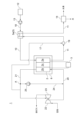
- FIG. 1 is a schematic diagram illustrating the configuration of a hydrogen production system according to a first embodiment of the present disclosure.
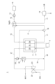
- FIG. FIG. 2 is a schematic diagram illustrating a configuration of a modified example of the hydrogen production system according to the first embodiment of the present disclosure.
- FIG. 2 is a schematic diagram illustrating a configuration of another modified example of the hydrogen production system according to the first embodiment of the present disclosure.
- FIG. 13 is a schematic diagram illustrating a configuration of yet another modified example of the hydrogen production system according to the first embodiment of the present disclosure.
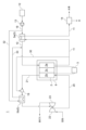
- FIG. 1 is a schematic diagram illustrating the configuration of a hydrogen production system according to a second embodiment of the present disclosure.
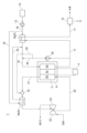
- FIG. 11 is a schematic diagram illustrating a configuration of a modified example of a hydrogen production system according to the second embodiment of the present disclosure.
- FIG. 11 is a schematic diagram illustrating a configuration of another modified example of the hydrogen production system according to the second embodiment of the present disclosure.
- FIG. 11 is a schematic diagram illustrating a configuration of yet another modified example of the hydrogen production system according to the second embodiment of the present disclosure.
- FIG. 11 is a schematic diagram illustrating a configuration of yet another modified example of the hydrogen production system according to the second embodiment of the present disclosure.
- FIG. 11 is a schematic diagram illustrating a configuration of yet another modified example of the hydrogen production system according to the second embodiment of the present disclosure.
- FIG. 11 is a schematic diagram illustrating the configuration of a hydrogen production system according to a third embodiment of the present disclosure.
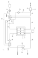
- a hydrogen production system 1 includes a solid oxide electrolysis cell (SOEC) 2 that electrolyzes water vapor, a power supply device 3 that applies a voltage to the SOEC 2, and a water vapor generator 5 that generates water vapor to be supplied to the SOEC 2.
- the water vapor generator 5 includes a main heat exchanger 5a, which is, for example, a boiler.
- the SOEC 2 includes a hydrogen electrode 2a, an oxygen electrode 2b, and a solid electrolyte 2c disposed between the hydrogen electrode 2a and the oxygen electrode 2b. Although only one SOEC 2 is illustrated in FIG. 1, multiple SOECs 2 may be housed within the housing 6.
- the power supply 3 is configured to apply a voltage between the hydrogen electrode 2a and the oxygen electrode 2b.
- the hydrogen electrode 2a is connected to a water vapor supply line 10 that connects the hydrogen electrode 2a to the main heat exchanger 5a, and a water vapor discharge line 11 through which water vapor discharged from the hydrogen electrode 2a flows.
- a water supply line 18 that supplies water to the main heat exchanger 5a is connected to the main heat exchanger 5a, and the other end of the water supply line 18 is connected to a water supply source 12.
- a pump 13 is provided on the water supply line 18.
- the main heat exchanger 5a is configured to perform heat exchange between the supply water supplied from the water supply source 12 via the water supply line 18 and the water vapor flowing through the water vapor discharge line 11.
- the water vapor exhaust line 11 is provided with a combustor 19.
- the water vapor flowing through the water vapor exhaust line 11 contains hydrogen, and the combustor 19 is intended to combust a portion of the hydrogen contained in the water vapor flowing through the water vapor exhaust line 11.
- the combustor 19 is connected to an oxygen-containing gas supply line 17 for supplying an oxygen-containing gas, such as air, to the combustor 19.
- a condenser 14 may be provided in the water vapor exhaust line 11 downstream of the main heat exchanger 5a.
- the oxygen electrode 2b is connected to a gas supply line 20 through which an oxygen-containing gas, such as air, supplied to the oxygen electrode 2b flows, and a gas exhaust line 21 through which exhaust gas discharged from the oxygen electrode 2b flows.
- a compressor 22 that compresses air is provided in the gas supply line 20, and a power turbine 23 driven by exhaust gas discharged from the oxygen electrode 2b is provided in the gas exhaust line 21.
- the water vapor (containing hydrogen) discharged from the hydrogen electrode 2a flows through the water vapor discharge line 11 and exchanges heat with the supply water pressurized by the pump 13 in the main heat exchanger 5a.
- the supply water is heated to become water vapor, and the water vapor discharged from the hydrogen electrode 2a is cooled.
- the water vapor discharged from the main heat exchanger 5a flows through the water vapor discharge line 11 and into the condenser 14.
- the condenser 14 the water vapor is condensed into water, and the water and hydrogen are separated into gas and liquid.
- the water condensed in the condenser 14 is either discharged or reused in an optional device, and the hydrogen is sent to a hydrogen consumption device or hydrogen storage device (not shown).
- the amount of water vapor electrolyzed in the SOEC2 when the amount of water vapor electrolyzed in the SOEC2 is increased by simply exchanging heat between the water supplied from the water supply source 12 and the water vapor discharged from the hydrogen electrode 2a, the amount of heat required to generate water vapor in the main heat exchanger 5a may be insufficient.
- a part of the hydrogen contained in the water vapor discharged from the hydrogen electrode 2a is burned in the combustor 19.
- the temperature of the water vapor containing the combustion gas generated by the combustion of hydrogen in the combustor 19 increases due to the combustion heat of hydrogen.
- the water vapor supplied to the main heat exchanger 5a becomes hotter, and the amount of water vapor generated by heat exchange with the water supplied to the main heat exchanger 5a can be increased. This makes it possible to supply the necessary amount of water vapor in the SOEC2.
- the temperature of the water vapor discharged from the combustor 19 can be adjusted by adjusting the amount of air supplied through the oxygen-containing gas supply line 17.
- the source of the oxygen-containing gas supplied to the combustor 19 is not specified, but a compressor may be provided in the oxygen-containing gas supply line 17 and the compressor may be driven to supply air in the atmosphere to the combustor 19, or the oxygen-containing gas may be supplied to the combustor 19 from a storage tank for the oxygen-containing gas or a production device for the oxygen-containing gas.
- the oxygen-containing gas supply line 17 may be provided to communicate the gas exhaust line 21 with the combustor 19, and a part of the exhaust gas discharged from the oxygen electrode 2b may be supplied to the combustor 19 as the oxygen-containing gas.
- an exhaust gas recirculation line 24 is provided that connects the gas supply line 20 and the gas exhaust line 21, and a booster 25 is provided in the exhaust gas recirculation line 24.
- the oxygen-containing gas supply line 17 may be configured to branch off from the gas exhaust line 21 downstream of position A where the exhaust gas recirculation line 24 branches off from the gas exhaust line 21.
- the oxygen-containing gas supply line 17 may be configured to branch off from the exhaust gas recirculation line 24 downstream of the booster 25.
- the exhaust gas pressurized by the booster 25 is supplied to the combustor 19, so there is no need to provide a compressor in the oxygen-containing gas supply line 17 to supply the exhaust gas to the combustor 19.
- the oxygen-containing gas supply line 17 may be configured to branch off from the exhaust gas recirculation line 24 between the booster 25 and the heat exchanger 26.
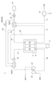
- a combustor 19 is provided in a gas exhaust line 21.
- a hydrogen-containing gas supply line 30 branched off from the water vapor exhaust line 11 is connected to the combustor 19.
- the steam generating device 5 includes a first heat exchanger 5b provided on the gas exhaust line 21 downstream of the combustor 19.
- the first heat exchanger 5b is for exchanging heat between a portion of the supply water supplied from the water supply source 12 and the exhaust gas flowing through the gas exhaust line 21.
- a water supply branch line 32 branched off from the water supply line 18 downstream of the pump 13 is connected to the first heat exchanger 5b in order to supply a portion of the supply water supplied from the water supply source 12 to the first heat exchanger 5b.
- Steam is generated in the first heat exchanger 5b by an operation described below, and a steam line 33 is provided that connects the first heat exchanger 5b to the steam supply line 10 in order to supply this steam to the steam supply line 10.
- the other configurations are the same as those of the first embodiment.
- the supply water that flows into the first heat exchanger 5b is heated and becomes water vapor by heat exchange with the exhaust gas discharged from the oxygen electrode 2b and flowing through the gas exhaust line 21. After being discharged from the first heat exchanger 5b, this water vapor flows through the water vapor line 33 and flows into the water vapor supply line 10, where it is mixed with the water vapor discharged from the main heat exchanger 5a and flows into the hydrogen electrode 2a.
- the operation of electrolysis of water vapor in the SOEC 2, the operation after the water vapor discharged from the hydrogen electrode 2a exchanges heat with the supply water in the main heat exchanger 5a, and the operation of supplying air to the oxygen electrode 2b are the same as in embodiment 1.
- the operation in the second embodiment when increasing the amount of water vapor supplied to the SOEC2 is different from that in the first embodiment.
- this operation in the second embodiment will be described.
- the hydrogen in the water vapor supplied to the combustor 19 via the hydrogen-containing gas supply line 30 is burned in the combustor 19 using the oxygen in the exhaust gas flowing through the gas exhaust line 21. Since the supplied water vapor has a temperature similar to that of the exhaust gas, the temperature of the exhaust gas (combustion exhaust gas) generated by the combustion of hydrogen in the combustor 19 increases due to the combustion heat of hydrogen.
- the exhaust gas supplied to the first heat exchanger 5b becomes hotter, and the amount of water vapor generated by heat exchange with the supply water supplied to the first heat exchanger 5b can be increased. This makes it possible to supply the necessary amount of water vapor in the SOEC2.
- the temperature of the exhaust gas discharged from the combustor 19 can be adjusted by adjusting the amount of water vapor supplied via the hydrogen-containing gas supply line 30.
- a second heat exchanger 5c for exchanging heat between a part of the supply water supplied from the water supply source 12 and the exhaust gas flowing through the gas exhaust line 21 may be further provided in the gas exhaust line 21 upstream of the combustor 19.
- Fig. 6 illustrates a configuration in which the supply water supplied from the water supply source 12 exchanges heat with the exhaust gas in the first heat exchanger 5b and then exchanges heat with the exhaust gas in the second heat exchanger 5c, but the configuration is not limited to this form.
- the supply water supplied from the water supply source 12 may exchange heat with the exhaust gas in the second heat exchanger 5c and then exchange heat with the exhaust gas in the first heat exchanger 5b, or the supply water supplied from the water supply source 12 may be split into two flows and then supplied to the first heat exchanger 5b and the second heat exchanger 5c, and the steam generated in the first heat exchanger 5b and the second heat exchanger 5c may flow into the steam supply line 10 after joining together or separately.
- the exhaust gas flowing into the combustor 19 is cooled by heat exchange with water or steam in the second heat exchanger 5c.
- the temperature of the exhaust gas flowing into the combustor 19 is lower than in the configuration of Figure 5. If the temperature of the combustion gas generated in the combustor 19 becomes too high, the amount of combustion possible in the combustor 19 is restricted due to the heat resistance of the combustor 19. However, by suppressing the temperature of the exhaust gas flowing into the combustor 19, the amount of combustion possible in the combustor 19 can be increased, and the range of the amount of water vapor that can be electrolyzed in the SOEC2 can be further expanded.
- the hydrogen-containing gas supply line 30 may be configured to branch off from the steam discharge line 11 downstream of position B where the steam recirculation line 34 branches off from the steam discharge line 11. With this configuration, the hydrogen contained in the steam can be supplied to the combustor 19 without directly affecting the steam circulation system (specifically, the steam flowing through the steam recirculation line 34).
- the hydrogen-containing gas supply line 30 may be configured to branch off from the steam recirculation line 34 downstream of the booster 35. With this configuration, the steam (hydrogen-containing gas) pressurized by the booster 35 is supplied to the combustor 19, eliminating the need to provide a booster in the hydrogen-containing gas supply line 30 to supply hydrogen to the combustor 19.
- the hydrogen production system 1 includes a low-temperature steam recirculation line 36 that connects the steam discharge line 11 downstream of the main heat exchanger 5a with the steam supply line 10 or an evaporator (not shown) in the main heat exchanger 5a, and a booster 37 provided in the low-temperature steam recirculation line 36
- the hydrogen-containing gas supply line 30 is configured to branch off from the low-temperature steam recirculation line 36 downstream of the booster 37
- the steam pressurized by the booster 37 is supplied to the combustor 19, as in the configuration of FIG. 8, so there is no need to provide a compressor in the hydrogen-containing gas supply line 30 to supply steam to the combustor 19.
- the booster 37 operates at a lower temperature, which allows for a reduction in compression power and a reduction in the cost of the booster itself.
- a first flow rate adjustment device 38 may be provided to adjust the flow rate of the supply water supplied from the water supply source 12 to the main heat exchanger 5a and the flow rate of the supply water flowing through the water supply branch line 32.
- the first flow rate adjustment device 38 may be, for example, a flow rate adjustment valve 38a provided in the water supply branch line 32.
- the flow rate adjustment valve may be provided in the water supply line 18 downstream of the position where the water supply branch line 32 branches off from the water supply line 18, rather than in the water supply branch line 32, or a flow rate adjustment valve may be provided in each of the water supply branch line 32 and the water supply line 18.
- a mechanism for adjusting the flow rate of the supply water supplied to the main heat exchanger 5a may be provided, and this mechanism may adjust the flow rate of the supply water to a flow rate required for the operation of the hydrogen production system 1. This makes it possible to individually adjust the amount of water vapor generated in the main heat exchanger 5a and the first heat exchanger 5b.
- the configuration of this mechanism is not particularly limited, and for example, when a pump 13 is provided, it may be a device for adjusting the discharge rate of the pump 13.
- FIG. 10 shows a configuration in which a first flow rate adjustment device 38 is provided in addition to the configuration of embodiment 2 (FIG. 5), but this is not limiting. The same effects can be obtained by the same operation even if a first flow rate adjustment device 38 is provided in each of the configurations of the modified examples of embodiment 2 (FIGS. 6 to 9).
- the steam generation device 5 includes a superheater for superheating the generated steam, and the combustion heat generated in the combustor is used as the heat source for the superheater.
- the same components as those in the first embodiment are given the same reference numerals, and detailed description thereof will be omitted.
- the configuration of the modified example described in the first embodiment can also be applied to the third embodiment.
- the steam generator 5 includes a main heat exchanger 5a and a superheater 5d in which the steam generated in the main heat exchanger 5a exchanges heat with the combustion gas generated in the combustor 19.
- the combustor 19 is connected to a steam extraction line 40 branched off from the steam discharge line 11 and an exhaust gas extraction line 41 branched off from the gas discharge line 21. That is, the steam extraction line 40 communicates the steam discharge line 11 with the combustor 19, and the exhaust gas extraction line 41 communicates the gas discharge line 21 with the combustor 19.
- the combustor 19 communicates with the superheater 5d via a combustion gas supply line 42, and communicates with the gas discharge line 21 via a combustion gas discharge line 43 downstream of a position C at which the exhaust gas extraction line 41 branches off from the gas discharge line 21.
- the water vapor extraction line 40 may be provided with a second flow rate adjustment device 44 that adjusts the flow rate of water vapor flowing through the water vapor extraction line 40.
- the exhaust gas extraction line 41 may be provided with a third flow rate adjustment device 45 that adjusts the flow rate of exhaust gas flowing through the exhaust gas extraction line 41.
- the configurations of the second flow rate adjustment device 44 and the third flow rate adjustment device 45 are not particularly limited, and may be, for example, flow rate adjustment valves 44a and 45a. The other configurations are the same as those of embodiment 1.
- the feed water supplied from the water supply source 12 exchanges heat with the steam discharged from the hydrogen electrode 2a, whereby the feed water is heated and becomes steam.
- the steam discharged from the main heat exchanger 5a is further superheated in the superheater 5d by heat exchange with the combustion gas generated in the combustor 19 through an operation described below, thereby becoming superheated steam.
- the temperature of the steam flowing into the hydrogen electrode 2a can be further increased, so that the operating conditions of the SOEC 2 can be maintained within a desired range even during low-load operation.
- a part of the water vapor flowing through the water vapor exhaust line 11 is supplied to the combustor 19 through the water vapor extraction line 40, and a part of the exhaust gas flowing through the gas exhaust line 21 is supplied through the exhaust gas extraction line 41, and the hydrogen contained in the water vapor is burned by the oxygen contained in the exhaust gas. Since the supplied water vapor and exhaust gas are at approximately the same temperature, the temperature of the combustion gas (combustion exhaust gas) generated by the combustion of hydrogen in the combustor 19 increases due to the combustion of hydrogen.
- the generated combustion gas (combustion exhaust gas) can be superheated by heat exchange with the water vapor discharged from the main heat exchanger 5a in the superheater 5d, and the amount of water vapor generated can be increased by heat exchange between the supply water and the main heat exchanger 5a and the superheater 5d.
- the combustion gas that has exchanged heat with the water vapor in the superheater 5d flows into the gas exhaust line 21 through the combustion gas exhaust line 43 and is mixed with the exhaust gas flowing through the gas exhaust line 21.
- the temperature of the water vapor flowing into the hydrogen electrode 2a can be controlled to a desired temperature by adjusting the degree of superheat of the water vapor in the superheater 5d using the flow rate control valve 44a, so that the operating conditions of the SOEC2 can be maintained in an optimal state.
- the flow rate control valve 45a is provided in the exhaust gas extraction line 41 in addition to the flow rate control valve 44a, the temperature of the water vapor flowing into the hydrogen electrode 2a can be controlled even more easily by adjusting the degree of superheat of the water vapor in the superheater 5d using the flow rate control valves 44a and 45a, so that stable operation can be achieved even in a wider operating range of the SOEC2.
- the steam generating device 5 includes a main heat exchanger 5a, and in the main heat exchanger 5a, the supply water supplied from the water supply source 12 exchanges heat with the steam containing the combustion gas generated in the combustor 19, thereby heating the supply water and generating steam.
- the steam generating device 5 includes a configuration including the main heat exchanger 5a and a first heat exchanger 5b, or a configuration including the main heat exchanger 5a, the first heat exchanger 5b, and a second heat exchanger 5c, and in the first heat exchanger 5b and the second heat exchanger 5c, a part of the supply water supplied from the water supply source 12 exchanges heat with the exhaust gas containing the combustion gas generated in the combustor 19 that combusts a part of the hydrogen contained in the steam discharged from the hydrogen electrode 2a, thereby heating the supply water and generating steam.
- the steam generator 5 includes a main heat exchanger 5a and a superheater 5d, and in the superheater 5d, the steam discharged from the main heat exchanger 5a exchanges heat with the combustion gas generated in the combustor 19 that burns a portion of the hydrogen contained in the steam discharged from the hydrogen electrode 2a, thereby further superheating the steam and generating superheated steam that flows into the hydrogen electrode 2a.
- the steam generator 5 is configured to heat at least a portion of the supply water (including the steam generated in the main heat exchanger 5a) to generate at least a portion of the steam by heat exchange between at least a portion of the supply water and the gas containing the combustion gas generated in the combustor 19 that burns a portion of the hydrogen contained in the steam discharged from the hydrogen electrode 2a, thereby increasing the overall amount of steam generated.
- a hydrogen production system includes: A solid oxide electrolysis cell (SOEC) (2) for electrolyzing water vapor; A steam generator (5) for heating supply water to generate the steam; a combustor (19) for combusting a portion of hydrogen contained in the water vapor discharged from the hydrogen electrode (2a) of the SOEC (2);
- the water vapor generating device (5) is configured so that at least a portion of the supply water is heated by heat exchange between at least a portion of the supply water and a gas including combustion gas generated in the combustor (19), thereby generating at least a portion of the water vapor.
- a hydrogen production system is the hydrogen production system according to [1], a water vapor discharge line (11) through which water vapor discharged from the hydrogen electrode (2a) flows;
- the water vapor generating device (5) includes a main heat exchanger (5a) for exchanging heat between the water vapor flowing through the water vapor discharge line (11) and the supply water,
- the combustor (19) is provided in the water vapor discharge line (11) upstream of the main heat exchanger (5a).
- a hydrogen production system is the hydrogen production system according to [2], a gas exhaust line (21) through which exhaust gas discharged from the oxygen electrode (2b) of the SOEC (2) flows; An oxygen-containing gas supply line (17) is provided which communicates between the gas discharge line (21) and the combustor (19).
- high-temperature exhaust gas can be used as the oxygen-containing gas required to burn hydrogen, reducing the amount of hydrogen consumed in the combustor to obtain the amount of heat required to generate water vapor, thereby reducing the cost of producing hydrogen in the hydrogen production system.
- a hydrogen production system is the hydrogen production system according to [3], a gas supply line (20) for supplying an oxygen-containing gas to the oxygen electrode (2b); an exhaust gas recirculation line (24) communicating between the gas supply line (20) and the gas exhaust line (21); and a booster (25) for boosting the pressure of the exhaust gas flowing through the exhaust gas recirculation line (24),
- the oxygen-containing gas supply line (17) branches off from the gas exhaust line (21) downstream of a position (A) where the exhaust gas recirculation line (24) branches off from the gas exhaust line (21).
- the combustor can stably use the high-temperature exhaust gas as the oxygen-containing gas required to burn hydrogen even at low loads or during load fluctuations, reducing the amount of hydrogen consumed in the combustor to obtain the heat required to generate water vapor, thereby reducing the cost of producing hydrogen in the hydrogen production system.
- a hydrogen production system is the hydrogen production system according to [3], a gas supply line (20) for supplying an oxygen-containing gas to the oxygen electrode (2b); an exhaust gas recirculation line (24) communicating between the gas supply line (20) and the gas exhaust line (21); and a booster (25) for boosting the pressure of the exhaust gas flowing through the exhaust gas recirculation line (24),
- the oxygen-containing gas supply line (17) branches off from the exhaust gas recirculation line (24) downstream of the booster (25).
- a hydrogen production system is the hydrogen production system according to [1], a water vapor discharge line (11) through which water vapor discharged from the hydrogen electrode (2a) flows; a gas exhaust line (21) through which exhaust gas discharged from the oxygen electrode (2b) of the SOEC (2) flows; Equipped with the water vapor generating device (5) further includes a first heat exchanger (5b) for exchanging heat between at least a part of the supply water and the exhaust gas discharged from the oxygen electrode (2b);
- the gas discharge line (21) is provided with the combustor (19) upstream of the first heat exchanger (5b),
- the combustor (19) communicates with the water vapor exhaust line (11) via a hydrogen-containing gas supply line (30).
- oxygen-containing gas is supplied to the water vapor discharged from the hydrogen electrode, which may reduce the purity of the product hydrogen in the hydrogen production system.
- water vapor containing hydrogen extracted from the water vapor flowing through the water vapor discharge line is supplied to the combustor, so that oxygen-containing gas is not supplied to the water vapor flowing through the water vapor discharge line, preventing a reduction in the purity of the product hydrogen in the hydrogen production system.
- a hydrogen production system is the hydrogen production system according to [6]
- the steam generating device (5) further includes a second heat exchanger (5c) provided in the gas exhaust line (21) upstream of the combustor (19),
- the first heat exchanger (5b) and the second heat exchanger (5c) are each configured to perform heat exchange between at least a portion of the supply water and the exhaust gas flowing through the gas exhaust line.
- the exhaust gas is cooled during heat exchange between the exhaust gas and the supply water in the second heat exchanger, and as a result, the temperature of the exhaust gas flowing into the combustor is lower than in the configuration [6]. If the temperature of the combustion gas generated in the combustor becomes too high, the amount of combustion possible in the combustor is restricted due to the heat resistance of the combustor. However, by lowering the temperature of the exhaust gas flowing into the combustor, the amount of combustion possible in the combustor can be increased, and therefore the amount of water vapor generated can be increased, and the range of water vapor amounts that can be electrolyzed in the SOEC can be further expanded.
- a hydrogen production system is the hydrogen production system according to [6],
- the water vapor generating device (5) includes a main heat exchanger (5a) for exchanging heat between at least a part of the supply water and water vapor flowing through the water vapor discharge line (11),
- the hydrogen production system (1) comprises: a water supply line (18) for supplying the feed water to the main heat exchanger (5a); a water supply branch line (32) communicating between the water supply line (18) and the first heat exchanger (5b); a steam supply line (10) communicating between the main heat exchanger (5a) and the hydrogen electrode (2a); a steam line (33) communicating between the first heat exchanger (5b) and the steam supply line (10);
- the system further includes a first flow rate adjustment device (38) for adjusting the flow rate of the supply water supplied to the main heat exchanger (5a) and the flow rate of the supply water flowing through the branch water supply line (32).
- the amount of heat applied to the supply water in each of the main heat exchanger and the first heat exchanger can be adjusted, so the range of the amount of water vapor that can be electrolyzed in the SOEC can be expanded while maximizing the use of excess heat generated in the hydrogen production system, making it possible to secure water vapor even if the amount of water vapor required for electrolysis increases.
- a hydrogen production system is the hydrogen production system according to [7],
- the water vapor generating device (5) includes a main heat exchanger (5a) for exchanging heat between at least a part of the supply water and water vapor flowing through the water vapor discharge line (11),
- the hydrogen production system (1) comprises: a water supply line (18) for supplying the feed water to the main heat exchanger (5a); a water supply branch line (32) communicating the water supply line (18) with both the first heat exchanger (5b) and the second heat exchanger (5c); a steam line (33) communicating both the first heat exchanger (5b) and the second heat exchanger (5c) with the steam supply line (10);
- the system further includes a first flow rate adjustment device (38) for adjusting the flow rate of the supply water supplied to the main heat exchanger (5a) and the flow rate of the supply water flowing through the branch water supply line (32).
- the hydrogen-containing gas supply line (30) may be connected downstream of the branch point (B) of the steam recirculation line (34) connected to the steam discharge line (11) (see FIG. 7), or downstream of the booster (35) of the steam recirculation line (34) (see FIG. 8), or downstream of the booster (37) of the low-temperature steam recirculation line (36) connected downstream of the main heat exchanger (5a) (see FIG. 9).
- a hydrogen production system is the hydrogen production system according to [1], a water vapor discharge line (11) through which water vapor discharged from the hydrogen electrode (2a) flows; a gas exhaust line (21) through which exhaust gas discharged from the oxygen electrode (2b) of the SOEC (2) flows; a steam extraction line (40) communicating between the steam discharge line (11) and the combustor (19); an exhaust gas extraction line (41) communicating between the gas discharge line (21) and the combustor (19);
- the water vapor generating device (5) a main heat exchanger (5a) for exchanging heat between the steam flowing through the steam discharge line (11) and the supply water;
- the steam generating system further includes a superheater (5d) for heat exchange between the steam generated in the main heat exchanger (5a) and the combustion gas generated in the combustor (19).
- the water vapor generated by the water vapor generator is superheated in the superheater, so the temperature of the water vapor flowing into the hydrogen electrode can be further increased, allowing the operating temperature of the SOEC to be maintained within a desired range even during low-load operation, and increasing operating costs can be suppressed.
- a hydrogen production system is the hydrogen production system according to [10]
- a second flow rate adjusting device (44) is provided in the water vapor extraction line (40) and adjusts the flow rate of water vapor flowing through the water vapor extraction line (40).
- the second flow rate control device adjusts the superheating of the steam in the superheater, making it easier to control the temperature of the steam flowing into the hydrogen electrode of the SOEC, so the operating temperature of the SOEC can be maintained within a desired range even during low-load operation, and increases in operating costs can be suppressed.
- a hydrogen production system is the hydrogen production system according to [11],
- the exhaust gas extraction system further includes a third flow rate adjusting device (45) that is provided in the exhaust gas extraction line (41) and adjusts the flow rate of the exhaust gas flowing through the exhaust gas extraction line (41).
- the second flow rate control device and the third flow rate control device adjust the superheating of the steam in the superheater, making it easier to control the temperature of the steam flowing into the hydrogen electrode of the SOEC, enabling stable operation of the SOEC over a wider operating range and preventing increases in operating costs.
- a hydrogen production system includes: A method for operating the hydrogen production system according to [9], The method includes adjusting the flow rate of the supply water through the water supply branch line (32) by the first flow rate adjustment device (38).
- the operating method of the hydrogen production system disclosed herein allows the amount of water vapor generated in each of the main heat exchanger and the first heat exchanger to be adjusted, making it possible to maximize the use of surplus heat generated in the hydrogen production system while appropriately supplying the amount of water vapor required for the electrolysis of water vapor in the SOEC even during low loads or load fluctuations.
- a hydrogen production system includes: A method for operating the hydrogen production system according to [11], comprising the steps of: The method includes a step of adjusting the degree of superheat of the steam in the superheater (5d) by the second flow rate adjustment device (44).
- the temperature of the water vapor flowing into the hydrogen electrode can be controlled to a desired temperature by adjusting the degree of superheating of the water vapor in the superheater using the second flow rate control device, so that the operating conditions of the SOEC can be maintained at optimal conditions.
- a hydrogen production system includes: A method for operating a hydrogen production system according to [12], comprising the steps of: The method includes a step of adjusting the degree of superheat of the steam in the superheater (5d) by the second flow rate adjustment device (44) and the third flow rate adjustment device (45).
- the flow rate of the hydrogen gas-containing gas and the flow rate of the oxygen-containing gas supplied to the combustor are adjusted by the second flow rate control device and the third flow rate control device according to the degree of superheating of the water vapor to be generated in the superheater, making it easier to control the temperature of the water vapor flowing into the hydrogen electrode, thereby enabling stable operation even in a wider operating range of the SOEC.
Landscapes
- Chemical & Material Sciences (AREA)
- Engineering & Computer Science (AREA)
- Chemical Kinetics & Catalysis (AREA)
- Electrochemistry (AREA)
- Materials Engineering (AREA)
- Metallurgy (AREA)
- Organic Chemistry (AREA)
- Automation & Control Theory (AREA)
- Inorganic Chemistry (AREA)
- Physics & Mathematics (AREA)
- Thermal Sciences (AREA)
- Mechanical Engineering (AREA)
- General Engineering & Computer Science (AREA)
- Electrolytic Production Of Non-Metals, Compounds, Apparatuses Therefor (AREA)
Abstract
Description
本願は、2023年3月28日に日本国特許庁に出願された特願2023-052203号に基づき優先権を主張し、その内容をここに援用する。
<本開示の実施形態1に係る水素製造システムの構成>
図1に示すように、本開示の実施形態1に係る水素製造システム1は、水蒸気を電気分解する固体酸化物形電解セル(SOEC)2と、SOEC2に電圧を印加する電源装置3と、SOEC2に供給される水蒸気を生成する水蒸気生成装置5とを備えている。水蒸気生成装置5は主熱交換器5aを備え、主熱交換器5aは例えばボイラである。
次に、本開示の実施形態1に係る水素製造システム1の動作について説明する。給水源12から供給された供給水が、ポンプ13により加圧されて給水ライン18を流通し、主熱交換器5aにおいて加熱されて水蒸気となる。主熱交換器5aにおいて生成した水蒸気は、水蒸気供給ライン10を流通して水素極2aに流入する。一方、コンプレッサ22によって圧縮された空気は、ガス供給ライン20を流通して酸素極2bに流入する。
H2O+2e-→H2+O2- ・・・(1)
2O2-→O2+4e- ・・・(2)
実施形態1では、燃焼器19に供給される酸素含有ガスの供給元を特定しなかったが、酸素含有ガス供給ライン17に圧縮機を設けて、圧縮機を駆動させることにより大気中の空気を燃焼器19に供給してもよいし、酸素含有ガスの貯蔵タンクや酸素含有ガスの製造装置から酸素含有ガスを燃焼器19に供給してもよい。また、図2に示すように、ガス排出ライン21と燃焼器19とを連通するように酸素含有ガス供給ライン17を設け、酸素極2bから排出された排ガスの一部を酸素含有ガスとして燃焼器19に供給してもよい。図2の構成によれば、酸素含有ガスとして高温(水蒸気と同程度の温度)の排ガスを利用することができるので、水蒸気を生成するのに必要な熱量を得るために燃焼器19で消費される水素の量を低減することができ、その結果、水素製造システム1における水素の製造コストを低減することができる。
次に、本開示の実施形態2に係る水素製造システムについて説明する。実施形態2に係る水素製造システムは、実施形態1に対して、燃焼器19を設ける位置を変更したものである。尚、実施形態2において、実施形態1の構成要件と同じものは同じ参照符号を付し、その詳細な説明は省略する。
図5に示すように、本開示の実施形態2に係る水素製造システム1では、燃焼器19はガス排出ライン21に設けられている。水素極2aから排出された水素を含む水蒸気(水素含有ガス)の一部を燃焼器19に供給するために、燃焼器19には、水蒸気排出ライン11から分岐した水素含有ガス供給ライン30が接続されている。
次に、本開示の実施形態2に係る水素製造システム1の動作について説明する。給水源12からの供給水は、一部が給水分岐ライン32を流通して第1熱交換器5bに流入し、残りが主熱交換器5aに流入する。主熱交換器5aでは、実施形態1と同様に、水素極2aから排出された水蒸気と供給水とが熱交換することにより供給水が加熱されて水蒸気となり、主熱交換器5aから排出される。
図6に示すように、水蒸気生成装置5の構成の一部として、燃焼器19よりも上流側でガス排出ライン21に、給水源12から供給される供給水の一部とガス排出ライン21を流通する排ガスとを熱交換する第2熱交換器5cをさらに追加して設けてもよい。図6には、給水源12から供給される供給水が第1熱交換器5bにおいて排ガスと熱交換した後に、第2熱交換器5cにおいて排ガスと熱交換する構成が描かれているが、この形態に限定するものではない。給水源12から供給される供給水が第2熱交換器5cにおいて排ガスと熱交換した後に、第1熱交換器5bにおいて排ガスと熱交換する構成であってもよいし、給水源12から供給される供給水が2つの流れに分割された後に第1熱交換器5b及び第2熱交換器5cのそれぞれに供給され、第1熱交換器5b及び第2熱交換器5cのそれぞれにおいて生成した水蒸気が合流した後に、又は別々に水蒸気供給ライン10に流入する構成であってもよい。
次に、本開示の実施形態3に係る水素製造システムについて説明する。実施形態3に係る水素製造システムは、実施形態1に対して、水蒸気生成装置5が、生成された水蒸気を過熱するための過熱器を備え、過熱器の熱源として燃焼器で発生した燃焼熱を利用するようにしたものである。尚、実施形態1において、実施形態1の構成要件と同じものは同じ参照符号を付し、その詳細な説明は省略する。また、構成上の矛盾がない限り、実施形態1で説明した変形例の構成を実施形態3にも適用可能である。
図11に示すように、本開示の実施形態3に係る水素製造システム1において、水蒸気生成装置5は、主熱交換器5aと、主熱交換器5aにおいて生成された水蒸気と燃焼器19において生成した燃焼ガスとが熱交換する過熱器5dとを備えている。燃焼器19には、水蒸気排出ライン11から分岐した水蒸気抽気ライン40と、ガス排出ライン21から分岐した排ガス抽気ライン41とがそれぞれ接続されている。すなわち、水蒸気抽気ライン40は水蒸気排出ライン11と燃焼器19とを連通し、排ガス抽気ライン41はガス排出ライン21と燃焼器19とを連通している。燃焼器19は、燃焼ガス供給ライン42を介して過熱器5dに連通し、燃焼ガス排出ライン43を介して、排ガス抽気ライン41がガス排出ライン21から分岐する位置Cよりも下流側でガス排出ライン21に連通している。
実施形態1と同様にして、主熱交換器5aでは、給水源12から供給された供給水と水素極2aから排出された水蒸気とが熱交換することにより供給水が加熱されて水蒸気となる。主熱交換器5aから排出された水蒸気は過熱器5dにおいて、後述する動作によって燃焼器19で生成した燃焼ガスと熱交換することによりさらに過熱された過熱蒸気となる。実施形態3では、水素極2aに流入する水蒸気の温度をさらに高めることができるので、SOEC2の動作条件を低負荷の運転時においても所望の範囲内に維持することができる。
本開示において、実施形態1では水蒸気生成装置5は主熱交換器5aを備え、主熱交換器5aにおいて、給水源12から供給された供給水と燃焼器19において生成した燃焼ガスを含む水蒸気とが熱交換することにより供給水が加熱されて水蒸気が生成される。実施形態2では水蒸気生成装置5は、主熱交換器5a及び第1熱交換器5bを備える構成、又は、主熱交換器5aと第1熱交換器5b及び第2熱交換器5cを備える構成を有し、第1熱交換器5b及び第2熱交換器5cにおいて、給水源12から供給された供給水の一部と、水素極2aから排出された水蒸気に含まれる水素の一部を燃焼させる燃焼器19において生成した燃焼ガスを含む排ガスとが熱交換することにより、供給水が加熱されて水蒸気が生成される。実施形態3では水蒸気生成装置5は、主熱交換器5a及び過熱器5dを備え、過熱器5dにおいて、主熱交換器5aから排出された水蒸気と、水素極2aから排出された水蒸気に含まれる水素の一部を燃焼させる燃焼器19において生成した燃焼ガスとが熱交換することにより、水蒸気がさらに過熱されて、水素極2aに流入する過熱蒸気が生成される。実施形態1~3によれば、水蒸気生成装置5は、水素製造システム1に、供給水の少なくとも一部と、水素極2aから排出された水蒸気に含まれる水素の一部を燃焼させる燃焼器19において生成した燃焼ガスを含むガスとが熱交換することにより、供給水(主熱交換器5aにおいて生成した水蒸気も含む)の少なくとも一部が加熱されて水蒸気の少なくとも一部が生成され、全体として生成される水蒸気量が増加するように構成されていると言える。
水蒸気を電気分解する固体酸化物形電解セル(SOEC)(2)と、
供給水を加熱して前記水蒸気を生成する水蒸気生成装置(5)と、
前記SOEC(2)の水素極(2a)から排出された水蒸気に含まれる水素の一部を燃焼させる燃焼器(19)と
を備え、
前記水蒸気生成装置(5)は、前記供給水の少なくとも一部と前記燃焼器(19)において生成した燃焼ガスを含むガスとが熱交換することにより前記供給水の少なくとも一部が加熱されて前記水蒸気の少なくとも一部が生成されるように構成されている。
前記水素極(2a)から排出された水蒸気が流通する水蒸気排出ライン(11)を備え、
前記水蒸気生成装置(5)は、前記水蒸気排出ライン(11)を流通する水蒸気と前記供給水とが熱交換する主熱交換器(5a)を備え、
前記水蒸気排出ライン(11)には、前記主熱交換器(5a)よりも上流側に前記燃焼器(19)が設けられている。
前記SOEC(2)の酸素極(2b)から排出された排ガスが流通するガス排出ライン(21)と、
前記ガス排出ライン(21)と前記燃焼器(19)とを連通する酸素含有ガス供給ライン(17)と
を備える。
前記酸素極(2b)に酸素含有ガスを供給するガス供給ライン(20)と、
前記ガス供給ライン(20)と前記ガス排出ライン(21)とを連通する排ガス再循環ライン(24)と、
前記排ガス再循環ライン(24)を流通する排ガスを昇圧する昇圧機(25)と
を備え、
前記酸素含有ガス供給ライン(17)は、前記排ガス再循環ライン(24)が前記ガス排出ライン(21)から分岐する位置(A)よりも下流側において前記ガス排出ライン(21)から分岐している。
前記酸素極(2b)に酸素含有ガスを供給するガス供給ライン(20)と、
前記ガス供給ライン(20)と前記ガス排出ライン(21)とを連通する排ガス再循環ライン(24)と、
前記排ガス再循環ライン(24)を流通する排ガスを昇圧する昇圧機(25)と
を備え、
前記酸素含有ガス供給ライン(17)は、前記昇圧機(25)よりも下流側において前記排ガス再循環ライン(24)から分岐している。
前記水素極(2a)から排出された水蒸気が流通する水蒸気排出ライン(11)と、
前記SOEC(2)の酸素極(2b)から排出された排ガスが流通するガス排出ライン(21)と、
を備え、
前記水蒸気生成装置(5)は、前記供給水の少なくとも一部と前記酸素極(2b)から排出された前記排ガスとが熱交換する第1熱交換器(5b)をさらに含み、
前記ガス排出ライン(21)には、前記第1熱交換器(5b)よりも上流側に前記燃焼器(19)が設けられ、
前記燃焼器(19)は、水素含有ガス供給ライン(30)を介して前記水蒸気排出ライン(11)と連通している。
前記水蒸気生成装置(5)は、前記燃焼器(19)よりも上流側で前記ガス排出ライン(21)に設けられた第2熱交換器(5c)をさらに備え、
前記第1熱交換器(5b)及び前記第2熱交換器(5c)のそれぞれにおいて、前記供給水の少なくとも一部と前記ガス排出ラインを流通する排ガスとが熱交換するように構成されている。
前記水蒸気生成装置(5)は、前記供給水の少なくとも一部と前記水蒸気排出ライン(11)を流通する水蒸気とが熱交換する主熱交換器(5a)を備え、
前記水素製造システム(1)は、
前記主熱交換器(5a)に前記供給水を供給する給水ライン(18)と、
前記給水ライン(18)と前記第1熱交換器(5b)とを連通する給水分岐ライン(32)と、
前記主熱交換器(5a)と前記水素極(2a)とを連通する水蒸気供給ライン(10)と、
前記第1熱交換器(5b)と前記水蒸気供給ライン(10)とを連通する水蒸気ライン(33)と、
前記主熱交換器(5a)に供給される前記供給水の流量と前記給水分岐ライン(32)を流通する供給水の流量とを調節する第1流量調節装置(38)と
を備える。
前記水蒸気生成装置(5)は、前記供給水の少なくとも一部と前記水蒸気排出ライン(11)を流通する水蒸気とが熱交換する主熱交換器(5a)を備え、
前記水素製造システム(1)は、
前記主熱交換器(5a)に前記供給水を供給する給水ライン(18)と、
前記給水ライン(18)と前記第1熱交換器(5b)及び前記第2熱交換器(5c)の両方とを連通する給水分岐ライン(32)と、
前記第1熱交換器(5b)及び前記第2熱交換器(5c)の両方と前記水蒸気供給ライン(10)とを連通する水蒸気ライン(33)と、
前記主熱交換器(5a)に供給される前記供給水の流量と前記給水分岐ライン(32)を流通する供給水の流量とを調節する第1流量調節装置(38)と
を備える。
前記水素極(2a)から排出された水蒸気が流通する水蒸気排出ライン(11)と、
前記SOEC(2)の酸素極(2b)から排出された排ガスが流通するガス排出ライン(21)と、
前記水蒸気排出ライン(11)と前記燃焼器(19)とを連通する水蒸気抽気ライン(40)と、
前記ガス排出ライン(21)と前記燃焼器(19)とを連通する排ガス抽気ライン(41)と
を備え、
前記水蒸気生成装置(5)は、
前記前記水蒸気排出ライン(11)を流通する水蒸気と前記供給水とが熱交換する主熱交換器(5a)と、
前記主熱交換器(5a)において生成された水蒸気と前記燃焼器(19)において生成した燃焼ガスとが熱交換する過熱器(5d)と
を備える。
前記水蒸気抽気ライン(40)に設けられるとともに該水蒸気抽気ライン(40)を流通する水蒸気の流量を調節する第2流量調節装置(44)を備える。
前記排ガス抽気ライン(41)に設けられるとともに該排ガス抽気ライン(41)を流通する排ガスの流量を調節する第3流量調節装置(45)を備える。
[9]の水素製造システムの運転方法であって、
前記第1流量調節装置(38)によって、前記給水分岐ライン(32)を流通する前記供給水の流量を調節するステップを含む。
[11]の水素製造システムの運転方法であって、
前記第2流量調節装置(44)によって前記過熱器(5d)における前記水蒸気の過熱度を調節するステップを含む。
[12]の水素製造システムの運転方法であって、
前記第2流量調節装置(44)及び前記第3流量調節装置(45)によって前記過熱器(5d)における前記水蒸気の過熱度を調節するステップを含む。
2 固体酸化物形電解セル(SOEC)
2a 水素極
2b 酸素極
5 水蒸気生成装置
5a 主熱交換器
5b 第1熱交換器
5c 第2熱交換器
5d 過熱器
10 水蒸気供給ライン
11 水蒸気排出ライン
12 給水源
13 ポンプ
17 酸素含有ガス供給ライン
18 給水ライン
19 燃焼器
20 ガス供給ライン
21 ガス排出ライン
24 排ガス再循環ライン
25,35,37 昇圧機
30 水素含有ガス供給ライン
32 給水分岐ライン
33 水蒸気ライン
38 第1流量調節装置
40 水蒸気抽気ライン
41 排ガス抽気ライン
44 第2流量調節装置
45 第3流量調節装置
Claims (15)
- 水蒸気を電気分解する固体酸化物形電解セル(SOEC)と、
供給水を加熱して前記水蒸気を生成する水蒸気生成装置と、
前記SOECの水素極から排出された水蒸気に含まれる水素の一部を燃焼させる燃焼器と
を備え、
前記水蒸気生成装置は、前記供給水の少なくとも一部と前記燃焼器において生成した燃焼ガスを含むガスとが熱交換することにより前記供給水の少なくとも一部が加熱されて前記水蒸気の少なくとも一部が生成されるように構成されている水素製造システム。 - 前記水素極から排出された水蒸気が流通する水蒸気排出ラインを備え、
前記水蒸気生成装置は、前記水蒸気排出ラインを流通する水蒸気と前記供給水とが熱交換する主熱交換器を備え、
前記水蒸気排出ラインには、前記主熱交換器よりも上流側に前記燃焼器が設けられている、請求項1に記載の水素製造システム。 - 前記SOECの酸素極から排出された排ガスが流通するガス排出ラインと、
前記ガス排出ラインと前記燃焼器とを連通する酸素含有ガス供給ラインと
を備える、請求項2に記載の水素製造システム。 - 前記酸素極に酸素含有ガスを供給するガス供給ラインと、
前記ガス供給ラインと前記ガス排出ラインとを連通する排ガス再循環ラインと、
前記排ガス再循環ラインを流通する排ガスを昇圧する昇圧機と
を備え、
前記酸素含有ガス供給ラインは、前記排ガス再循環ラインが前記ガス排出ラインから分岐する位置よりも下流側において前記ガス排出ラインから分岐している、請求項3に記載の水素製造システム。 - 前記酸素極に酸素含有ガスを供給するガス供給ラインと、
前記ガス供給ラインと前記ガス排出ラインとを連通する排ガス再循環ラインと、
前記排ガス再循環ラインを流通する排ガスを昇圧する昇圧機と
を備え、
前記酸素含有ガス供給ラインは、前記昇圧機よりも下流側において前記排ガス再循環ラインから分岐している、請求項3に記載の水素製造システム。 - 前記水素極から排出された水蒸気が流通する水蒸気排出ラインと、
前記SOECの酸素極から排出された排ガスが流通するガス排出ラインと、
を備え、
前記水蒸気生成装置は、前記供給水の少なくとも一部と前記酸素極から排出された前記排ガスとが熱交換する第1熱交換器をさらに含み、
前記ガス排出ラインには、前記第1熱交換器よりも上流側に前記燃焼器が設けられ、
前記燃焼器は、水素含有ガス供給ラインを介して前記水蒸気排出ラインと連通している、請求項1に記載の水素製造システム。 - 前記水蒸気生成装置は、前記燃焼器よりも上流側で前記ガス排出ラインに設けられた第2熱交換器をさらに備え、
前記第1熱交換器及び前記第2熱交換器のそれぞれにおいて、前記供給水の少なくとも一部と前記ガス排出ラインを流通する排ガスとが熱交換するように構成されている、請求項6に記載の水素製造システム。 - 前記水蒸気生成装置は、前記供給水の少なくとも一部と前記水蒸気排出ラインを流通する水蒸気とが熱交換する主熱交換器を備え、
前記水素製造システムは、
前記主熱交換器に前記供給水を供給する給水ラインと、
前記給水ラインと前記第1熱交換器とを連通する給水分岐ラインと、
前記主熱交換器と前記水素極とを連通する水蒸気供給ラインと、
前記第1熱交換器と前記水蒸気供給ラインとを連通する水蒸気ラインと、
前記主熱交換器に供給される前記供給水の流量と前記給水分岐ラインを流通する供給水の流量とを調節する第1流量調節装置と
を備える、請求項6に記載の水素製造システム。 - 前記水蒸気生成装置は、前記供給水の少なくとも一部と前記水蒸気排出ラインを流通する水蒸気とが熱交換する主熱交換器を備え、
前記水素製造システムは、
前記主熱交換器に前記供給水を供給する給水ラインと、
前記給水ラインと前記第1熱交換器及び前記第2熱交換器の両方とを連通する給水分岐ラインと、
前記第1熱交換器及び前記第2熱交換器の両方と前記水蒸気供給ラインとを連通する水蒸気ラインと、
前記主熱交換器に供給される前記供給水の流量と前記給水分岐ラインを流通する供給水の流量とを調節する第1流量調節装置と
を備える、請求項7に記載の水素製造システム。 - 前記水素極から排出された水蒸気が流通する水蒸気排出ラインと、
前記SOECの酸素極から排出された排ガスが流通するガス排出ラインと、
前記水蒸気排出ラインと前記燃焼器とを連通する水蒸気抽気ラインと、
前記ガス排出ラインと前記燃焼器とを連通する排ガス抽気ラインと
を備え、
前記水蒸気生成装置は、
前記前記水蒸気排出ラインを流通する水蒸気と前記供給水とが熱交換する主熱交換器と、
前記主熱交換器において生成された水蒸気と前記燃焼器において生成した燃焼ガスとが熱交換する過熱器と
を備える、請求項1に記載の水素製造システム。 - 前記水蒸気抽気ラインに設けられるとともに該水蒸気抽気ラインを流通する水蒸気の流量を調節する第2流量調節装置を備える、請求項10に記載の水素製造システム。
- 前記排ガス抽気ラインに設けられるとともに該排ガス抽気ラインを流通する排ガスの流量を調節する第3流量調節装置を備える、請求項11に記載の水素製造システム。
- 前記第1流量調節装置によって、前記給水分岐ラインを流通する前記供給水の流量を調節するステップを含む、請求項9に記載の水素製造システムの運転方法。
- 前記第2流量調節装置によって前記過熱器における前記水蒸気の過熱度を調節するステップを含む、請求項11に記載の水素製造システムの運転方法。
- 前記第2流量調節装置及び前記第3流量調節装置によって前記過熱器における前記水蒸気の過熱度を調節するステップを含む、請求項12に記載の水素製造システムの運転方法。
Priority Applications (2)
| Application Number | Priority Date | Filing Date | Title |
|---|---|---|---|
| EP24778575.1A EP4667623A1 (en) | 2023-03-28 | 2024-01-19 | Hydrogen production system and method for operating hydrogen production system |
| CN202480017948.XA CN120882909A (zh) | 2023-03-28 | 2024-01-19 | 氢制造系统及氢制造系统的运行方法 |
Applications Claiming Priority (2)
| Application Number | Priority Date | Filing Date | Title |
|---|---|---|---|
| JP2023052203A JP7609912B2 (ja) | 2023-03-28 | 2023-03-28 | 水素製造システム及び水素製造システムの運転方法 |
| JP2023-052203 | 2023-03-28 |
Publications (1)
| Publication Number | Publication Date |
|---|---|
| WO2024202429A1 true WO2024202429A1 (ja) | 2024-10-03 |
Family
ID=92904922
Family Applications (1)
| Application Number | Title | Priority Date | Filing Date |
|---|---|---|---|
| PCT/JP2024/001397 Ceased WO2024202429A1 (ja) | 2023-03-28 | 2024-01-19 | 水素製造システム及び水素製造システムの運転方法 |
Country Status (4)
| Country | Link |
|---|---|
| EP (1) | EP4667623A1 (ja) |
| JP (1) | JP7609912B2 (ja) |
| CN (1) | CN120882909A (ja) |
| WO (1) | WO2024202429A1 (ja) |
Citations (14)
| Publication number | Priority date | Publication date | Assignee | Title |
|---|---|---|---|---|
| JPH0441689A (ja) * | 1990-06-05 | 1992-02-12 | Mitsubishi Heavy Ind Ltd | 水素製造装置 |
| JPH094418A (ja) * | 1995-06-16 | 1997-01-07 | Mitsubishi Heavy Ind Ltd | 水素燃焼電力貯蔵装置 |
| JP2009001878A (ja) * | 2007-06-22 | 2009-01-08 | Toshiba Corp | 高温水蒸気電解方法および装置 |
| WO2010151157A1 (en) * | 2009-06-22 | 2010-12-29 | Leonardo Jr I Mendoza | High temperature electrolysis system |
| JP2017520685A (ja) * | 2014-06-06 | 2017-07-27 | サンファイアー ゲゼルシャフト ミット ベシュレンクテル ハフツングSunFire GmbH | 再循環する洗浄媒体を用いる電解法及び電解装置 |
| JP2019534940A (ja) * | 2016-09-19 | 2019-12-05 | コミッサリア ア レネルジー アトミーク エ オ ゼネルジ ザルタナテイヴ | 電解槽と結合された水素化物タンクを含む水の高温可逆電解用システム |
| CN113621977A (zh) * | 2021-09-14 | 2021-11-09 | 北京思伟特新能源科技有限公司 | 一种具有固体氧化物电解槽的制氢系统 |
| JP7039504B2 (ja) | 2019-02-08 | 2022-03-22 | 東芝エネルギーシステムズ株式会社 | 水素製造プラントの制御装置及び制御方法 |
| CN114774956A (zh) * | 2022-05-06 | 2022-07-22 | 西安热工研究院有限公司 | 一种基于固体氧化物制氢的储能调峰系统及方法 |
| CN115265212A (zh) * | 2022-07-21 | 2022-11-01 | 广州能源检测研究院 | 一种陶瓷窑炉氢气燃料燃烧系统及节能工艺 |
| US20220348489A1 (en) * | 2019-07-18 | 2022-11-03 | Linde Gmbh | Method for operating a fired furnace and arrangement comprising such a furnace |
| CN218710890U (zh) * | 2022-09-16 | 2023-03-24 | 中海石油气电集团有限责任公司 | 一种燃气发电耦合soec制氢系统 |
| JP2023052203A (ja) | 2017-11-27 | 2023-04-11 | ノバモント・ソシエタ・ペル・アチオニ | 再生可能資源由来の1,4-ブタンジオールの製造方法及びそれから得られるポリエステル |
| WO2023243110A1 (ja) * | 2022-06-13 | 2023-12-21 | 東洋ガラス株式会社 | ガラス及び水素を製造するプラント、及びガラス及び水素の製造方法 |
-
2023
- 2023-03-28 JP JP2023052203A patent/JP7609912B2/ja active Active
-
2024
- 2024-01-19 EP EP24778575.1A patent/EP4667623A1/en active Pending
- 2024-01-19 WO PCT/JP2024/001397 patent/WO2024202429A1/ja not_active Ceased
- 2024-01-19 CN CN202480017948.XA patent/CN120882909A/zh active Pending
Patent Citations (14)
| Publication number | Priority date | Publication date | Assignee | Title |
|---|---|---|---|---|
| JPH0441689A (ja) * | 1990-06-05 | 1992-02-12 | Mitsubishi Heavy Ind Ltd | 水素製造装置 |
| JPH094418A (ja) * | 1995-06-16 | 1997-01-07 | Mitsubishi Heavy Ind Ltd | 水素燃焼電力貯蔵装置 |
| JP2009001878A (ja) * | 2007-06-22 | 2009-01-08 | Toshiba Corp | 高温水蒸気電解方法および装置 |
| WO2010151157A1 (en) * | 2009-06-22 | 2010-12-29 | Leonardo Jr I Mendoza | High temperature electrolysis system |
| JP2017520685A (ja) * | 2014-06-06 | 2017-07-27 | サンファイアー ゲゼルシャフト ミット ベシュレンクテル ハフツングSunFire GmbH | 再循環する洗浄媒体を用いる電解法及び電解装置 |
| JP2019534940A (ja) * | 2016-09-19 | 2019-12-05 | コミッサリア ア レネルジー アトミーク エ オ ゼネルジ ザルタナテイヴ | 電解槽と結合された水素化物タンクを含む水の高温可逆電解用システム |
| JP2023052203A (ja) | 2017-11-27 | 2023-04-11 | ノバモント・ソシエタ・ペル・アチオニ | 再生可能資源由来の1,4-ブタンジオールの製造方法及びそれから得られるポリエステル |
| JP7039504B2 (ja) | 2019-02-08 | 2022-03-22 | 東芝エネルギーシステムズ株式会社 | 水素製造プラントの制御装置及び制御方法 |
| US20220348489A1 (en) * | 2019-07-18 | 2022-11-03 | Linde Gmbh | Method for operating a fired furnace and arrangement comprising such a furnace |
| CN113621977A (zh) * | 2021-09-14 | 2021-11-09 | 北京思伟特新能源科技有限公司 | 一种具有固体氧化物电解槽的制氢系统 |
| CN114774956A (zh) * | 2022-05-06 | 2022-07-22 | 西安热工研究院有限公司 | 一种基于固体氧化物制氢的储能调峰系统及方法 |
| WO2023243110A1 (ja) * | 2022-06-13 | 2023-12-21 | 東洋ガラス株式会社 | ガラス及び水素を製造するプラント、及びガラス及び水素の製造方法 |
| CN115265212A (zh) * | 2022-07-21 | 2022-11-01 | 广州能源检测研究院 | 一种陶瓷窑炉氢气燃料燃烧系统及节能工艺 |
| CN218710890U (zh) * | 2022-09-16 | 2023-03-24 | 中海石油气电集团有限责任公司 | 一种燃气发电耦合soec制氢系统 |
Non-Patent Citations (1)
| Title |
|---|
| See also references of EP4667623A1 |
Also Published As
| Publication number | Publication date |
|---|---|
| JP2024140857A (ja) | 2024-10-10 |
| JP7609912B2 (ja) | 2025-01-07 |
| CN120882909A (zh) | 2025-10-31 |
| EP4667623A1 (en) | 2025-12-24 |
Similar Documents
| Publication | Publication Date | Title |
|---|---|---|
| KR101352198B1 (ko) | 연료전지 하이브리드 시스템 | |
| US7621133B2 (en) | Methods and apparatus for starting up combined cycle power systems | |
| JP5185657B2 (ja) | コンバインドシステム | |
| JP5004156B2 (ja) | 発電設備 | |
| US20070287046A1 (en) | Combined Power Generation Equipment | |
| JPH02168569A (ja) | 燃料電池発電システム | |
| JPS62184774A (ja) | 燃料電池発電システム及びその起動方法 | |
| JP2005038817A (ja) | 燃料電池・常圧タービン・ハイブリッドシステム | |
| JPH0622148B2 (ja) | 溶融炭酸塩型燃料電池発電プラント | |
| JP2002168135A (ja) | 燃料加湿装置の制御 | |
| JP4146411B2 (ja) | 複合発電システム及び複合発電システムの運転方法 | |
| JP2585210B2 (ja) | 燃料電池発電プラント | |
| JP7609912B2 (ja) | 水素製造システム及び水素製造システムの運転方法 | |
| KR100405142B1 (ko) | 연료전지 발전시스템 | |
| JP4212322B2 (ja) | 燃料電池とマイクロガスタービンのコンバインド発電設備とその起動方法 | |
| US20250137151A1 (en) | Boiler system and method for operating boiler system | |
| JP2001015134A (ja) | 燃料電池とガスタービンの複合発電装置 | |
| JP4212089B2 (ja) | 燃料電池とマイクロガスタービンのコンバインド発電設備とその起動方法 | |
| JP4357819B2 (ja) | 燃料電池とマイクロガスタービンのコンバインド発電設備の熱電比変更方法 | |
| JP6382755B2 (ja) | 燃料電池複合発電システム、およびその運転方法 | |
| JPH051508A (ja) | フレキシブルコージエネレーシヨンプラントの運転方法 | |
| JP3509141B2 (ja) | 燃料電池発電装置 | |
| JPH05303971A (ja) | 溶融炭酸塩型燃料電池発電システム | |
| CN120120083A (zh) | 一种联合机组运行方法及循环发电系统 | |
| JP3582131B2 (ja) | 溶融炭酸塩型燃料電池発電装置 |
Legal Events
| Date | Code | Title | Description |
|---|---|---|---|
| 121 | Ep: the epo has been informed by wipo that ep was designated in this application |
Ref document number: 24778575 Country of ref document: EP Kind code of ref document: A1 |
|
| WWE | Wipo information: entry into national phase |
Ref document number: 202480017948.X Country of ref document: CN |
|
| WWE | Wipo information: entry into national phase |
Ref document number: 2024778575 Country of ref document: EP |
|
| NENP | Non-entry into the national phase |
Ref country code: DE |
|
| WWP | Wipo information: published in national office |
Ref document number: 202480017948.X Country of ref document: CN |
|
| ENP | Entry into the national phase |
Ref document number: 2024778575 Country of ref document: EP Effective date: 20250918 |
|
| WWP | Wipo information: published in national office |
Ref document number: 2024778575 Country of ref document: EP |