WO2024203411A1 - 鋼板、部材およびそれらの製造方法 - Google Patents
鋼板、部材およびそれらの製造方法 Download PDFInfo
- Publication number
- WO2024203411A1 WO2024203411A1 PCT/JP2024/010116 JP2024010116W WO2024203411A1 WO 2024203411 A1 WO2024203411 A1 WO 2024203411A1 JP 2024010116 W JP2024010116 W JP 2024010116W WO 2024203411 A1 WO2024203411 A1 WO 2024203411A1
- Authority
- WO
- WIPO (PCT)
- Prior art keywords
- less
- temperature
- steel sheet
- cooling
- average
- Prior art date
- Legal status (The legal status is an assumption and is not a legal conclusion. Google has not performed a legal analysis and makes no representation as to the accuracy of the status listed.)
- Ceased
Links
Images


Classifications
-
- C—CHEMISTRY; METALLURGY
- C23—COATING METALLIC MATERIAL; COATING MATERIAL WITH METALLIC MATERIAL; CHEMICAL SURFACE TREATMENT; DIFFUSION TREATMENT OF METALLIC MATERIAL; COATING BY VACUUM EVAPORATION, BY SPUTTERING, BY ION IMPLANTATION OR BY CHEMICAL VAPOUR DEPOSITION, IN GENERAL; INHIBITING CORROSION OF METALLIC MATERIAL OR INCRUSTATION IN GENERAL
- C23C—COATING METALLIC MATERIAL; COATING MATERIAL WITH METALLIC MATERIAL; SURFACE TREATMENT OF METALLIC MATERIAL BY DIFFUSION INTO THE SURFACE, BY CHEMICAL CONVERSION OR SUBSTITUTION; COATING BY VACUUM EVAPORATION, BY SPUTTERING, BY ION IMPLANTATION OR BY CHEMICAL VAPOUR DEPOSITION, IN GENERAL
- C23C2/00—Hot-dipping or immersion processes for applying the coating material in the molten state without affecting the shape; Apparatus therefor
- C23C2/02—Pretreatment of the material to be coated, e.g. for coating on selected surface areas
-
- B—PERFORMING OPERATIONS; TRANSPORTING
- B32—LAYERED PRODUCTS
- B32B—LAYERED PRODUCTS, i.e. PRODUCTS BUILT-UP OF STRATA OF FLAT OR NON-FLAT, e.g. CELLULAR OR HONEYCOMB, FORM
- B32B15/00—Layered products comprising a layer of metal
- B32B15/01—Layered products comprising a layer of metal all layers being exclusively metallic
- B32B15/013—Layered products comprising a layer of metal all layers being exclusively metallic one layer being formed of an iron alloy or steel, another layer being formed of a metal other than iron or aluminium
-
- C—CHEMISTRY; METALLURGY
- C21—METALLURGY OF IRON
- C21D—MODIFYING THE PHYSICAL STRUCTURE OF FERROUS METALS; GENERAL DEVICES FOR HEAT TREATMENT OF FERROUS OR NON-FERROUS METALS OR ALLOYS; MAKING METAL MALLEABLE, e.g. BY DECARBURISATION OR TEMPERING
- C21D1/00—General methods or devices for heat treatment, e.g. annealing, hardening, quenching or tempering
- C21D1/18—Hardening; Quenching with or without subsequent tempering
- C21D1/25—Hardening, combined with annealing between 300 degrees Celsius and 600 degrees Celsius, i.e. heat refining ("Vergüten")
-
- C—CHEMISTRY; METALLURGY
- C21—METALLURGY OF IRON
- C21D—MODIFYING THE PHYSICAL STRUCTURE OF FERROUS METALS; GENERAL DEVICES FOR HEAT TREATMENT OF FERROUS OR NON-FERROUS METALS OR ALLOYS; MAKING METAL MALLEABLE, e.g. BY DECARBURISATION OR TEMPERING
- C21D1/00—General methods or devices for heat treatment, e.g. annealing, hardening, quenching or tempering
- C21D1/26—Methods of annealing
-
- C—CHEMISTRY; METALLURGY
- C21—METALLURGY OF IRON
- C21D—MODIFYING THE PHYSICAL STRUCTURE OF FERROUS METALS; GENERAL DEVICES FOR HEAT TREATMENT OF FERROUS OR NON-FERROUS METALS OR ALLOYS; MAKING METAL MALLEABLE, e.g. BY DECARBURISATION OR TEMPERING
- C21D6/00—Heat treatment of ferrous alloys
- C21D6/005—Heat treatment of ferrous alloys containing Mn
-
- C—CHEMISTRY; METALLURGY
- C21—METALLURGY OF IRON
- C21D—MODIFYING THE PHYSICAL STRUCTURE OF FERROUS METALS; GENERAL DEVICES FOR HEAT TREATMENT OF FERROUS OR NON-FERROUS METALS OR ALLOYS; MAKING METAL MALLEABLE, e.g. BY DECARBURISATION OR TEMPERING
- C21D6/00—Heat treatment of ferrous alloys
- C21D6/008—Heat treatment of ferrous alloys containing Si
-
- C—CHEMISTRY; METALLURGY
- C21—METALLURGY OF IRON
- C21D—MODIFYING THE PHYSICAL STRUCTURE OF FERROUS METALS; GENERAL DEVICES FOR HEAT TREATMENT OF FERROUS OR NON-FERROUS METALS OR ALLOYS; MAKING METAL MALLEABLE, e.g. BY DECARBURISATION OR TEMPERING
- C21D8/00—Modifying the physical properties of ferrous metals or ferrous alloys by deformation combined with, or followed by, heat treatment
- C21D8/02—Modifying the physical properties of ferrous metals or ferrous alloys by deformation combined with, or followed by, heat treatment during manufacturing of plates or strips
-
- C—CHEMISTRY; METALLURGY
- C21—METALLURGY OF IRON
- C21D—MODIFYING THE PHYSICAL STRUCTURE OF FERROUS METALS; GENERAL DEVICES FOR HEAT TREATMENT OF FERROUS OR NON-FERROUS METALS OR ALLOYS; MAKING METAL MALLEABLE, e.g. BY DECARBURISATION OR TEMPERING
- C21D8/00—Modifying the physical properties of ferrous metals or ferrous alloys by deformation combined with, or followed by, heat treatment
- C21D8/02—Modifying the physical properties of ferrous metals or ferrous alloys by deformation combined with, or followed by, heat treatment during manufacturing of plates or strips
- C21D8/0221—Modifying the physical properties of ferrous metals or ferrous alloys by deformation combined with, or followed by, heat treatment during manufacturing of plates or strips characterised by the working steps
- C21D8/0226—Hot rolling
-
- C—CHEMISTRY; METALLURGY
- C21—METALLURGY OF IRON
- C21D—MODIFYING THE PHYSICAL STRUCTURE OF FERROUS METALS; GENERAL DEVICES FOR HEAT TREATMENT OF FERROUS OR NON-FERROUS METALS OR ALLOYS; MAKING METAL MALLEABLE, e.g. BY DECARBURISATION OR TEMPERING
- C21D8/00—Modifying the physical properties of ferrous metals or ferrous alloys by deformation combined with, or followed by, heat treatment
- C21D8/02—Modifying the physical properties of ferrous metals or ferrous alloys by deformation combined with, or followed by, heat treatment during manufacturing of plates or strips
- C21D8/0221—Modifying the physical properties of ferrous metals or ferrous alloys by deformation combined with, or followed by, heat treatment during manufacturing of plates or strips characterised by the working steps
- C21D8/0236—Cold rolling
-
- C—CHEMISTRY; METALLURGY
- C21—METALLURGY OF IRON
- C21D—MODIFYING THE PHYSICAL STRUCTURE OF FERROUS METALS; GENERAL DEVICES FOR HEAT TREATMENT OF FERROUS OR NON-FERROUS METALS OR ALLOYS; MAKING METAL MALLEABLE, e.g. BY DECARBURISATION OR TEMPERING
- C21D8/00—Modifying the physical properties of ferrous metals or ferrous alloys by deformation combined with, or followed by, heat treatment
- C21D8/02—Modifying the physical properties of ferrous metals or ferrous alloys by deformation combined with, or followed by, heat treatment during manufacturing of plates or strips
- C21D8/0247—Modifying the physical properties of ferrous metals or ferrous alloys by deformation combined with, or followed by, heat treatment during manufacturing of plates or strips characterised by the heat treatment
- C21D8/0263—Modifying the physical properties of ferrous metals or ferrous alloys by deformation combined with, or followed by, heat treatment during manufacturing of plates or strips characterised by the heat treatment following hot rolling
-
- C—CHEMISTRY; METALLURGY
- C21—METALLURGY OF IRON
- C21D—MODIFYING THE PHYSICAL STRUCTURE OF FERROUS METALS; GENERAL DEVICES FOR HEAT TREATMENT OF FERROUS OR NON-FERROUS METALS OR ALLOYS; MAKING METAL MALLEABLE, e.g. BY DECARBURISATION OR TEMPERING
- C21D8/00—Modifying the physical properties of ferrous metals or ferrous alloys by deformation combined with, or followed by, heat treatment
- C21D8/02—Modifying the physical properties of ferrous metals or ferrous alloys by deformation combined with, or followed by, heat treatment during manufacturing of plates or strips
- C21D8/0247—Modifying the physical properties of ferrous metals or ferrous alloys by deformation combined with, or followed by, heat treatment during manufacturing of plates or strips characterised by the heat treatment
- C21D8/0273—Final recrystallisation annealing
-
- C—CHEMISTRY; METALLURGY
- C21—METALLURGY OF IRON
- C21D—MODIFYING THE PHYSICAL STRUCTURE OF FERROUS METALS; GENERAL DEVICES FOR HEAT TREATMENT OF FERROUS OR NON-FERROUS METALS OR ALLOYS; MAKING METAL MALLEABLE, e.g. BY DECARBURISATION OR TEMPERING
- C21D9/00—Heat treatment, e.g. annealing, hardening, quenching or tempering, adapted for particular articles; Furnaces therefor
- C21D9/46—Heat treatment, e.g. annealing, hardening, quenching or tempering, adapted for particular articles; Furnaces therefor for sheet metals
-
- C—CHEMISTRY; METALLURGY
- C22—METALLURGY; FERROUS OR NON-FERROUS ALLOYS; TREATMENT OF ALLOYS OR NON-FERROUS METALS
- C22C—ALLOYS
- C22C38/00—Ferrous alloys, e.g. steel alloys
- C22C38/002—Ferrous alloys, e.g. steel alloys containing In, Mg, or other elements not provided for in one single group C22C38/001 - C22C38/60
-
- C—CHEMISTRY; METALLURGY
- C22—METALLURGY; FERROUS OR NON-FERROUS ALLOYS; TREATMENT OF ALLOYS OR NON-FERROUS METALS
- C22C—ALLOYS
- C22C38/00—Ferrous alloys, e.g. steel alloys
- C22C38/005—Ferrous alloys, e.g. steel alloys containing rare earths, i.e. Sc, Y, Lanthanides
-
- C—CHEMISTRY; METALLURGY
- C22—METALLURGY; FERROUS OR NON-FERROUS ALLOYS; TREATMENT OF ALLOYS OR NON-FERROUS METALS
- C22C—ALLOYS
- C22C38/00—Ferrous alloys, e.g. steel alloys
- C22C38/008—Ferrous alloys, e.g. steel alloys containing tin
-
- C—CHEMISTRY; METALLURGY
- C22—METALLURGY; FERROUS OR NON-FERROUS ALLOYS; TREATMENT OF ALLOYS OR NON-FERROUS METALS
- C22C—ALLOYS
- C22C38/00—Ferrous alloys, e.g. steel alloys
- C22C38/02—Ferrous alloys, e.g. steel alloys containing silicon
-
- C—CHEMISTRY; METALLURGY
- C22—METALLURGY; FERROUS OR NON-FERROUS ALLOYS; TREATMENT OF ALLOYS OR NON-FERROUS METALS
- C22C—ALLOYS
- C22C38/00—Ferrous alloys, e.g. steel alloys
- C22C38/04—Ferrous alloys, e.g. steel alloys containing manganese
-
- C—CHEMISTRY; METALLURGY
- C22—METALLURGY; FERROUS OR NON-FERROUS ALLOYS; TREATMENT OF ALLOYS OR NON-FERROUS METALS
- C22C—ALLOYS
- C22C38/00—Ferrous alloys, e.g. steel alloys
- C22C38/14—Ferrous alloys, e.g. steel alloys containing titanium or zirconium
-
- C—CHEMISTRY; METALLURGY
- C22—METALLURGY; FERROUS OR NON-FERROUS ALLOYS; TREATMENT OF ALLOYS OR NON-FERROUS METALS
- C22C—ALLOYS
- C22C38/00—Ferrous alloys, e.g. steel alloys
- C22C38/18—Ferrous alloys, e.g. steel alloys containing chromium
- C22C38/20—Ferrous alloys, e.g. steel alloys containing chromium with copper
-
- C—CHEMISTRY; METALLURGY
- C22—METALLURGY; FERROUS OR NON-FERROUS ALLOYS; TREATMENT OF ALLOYS OR NON-FERROUS METALS
- C22C—ALLOYS
- C22C38/00—Ferrous alloys, e.g. steel alloys
- C22C38/18—Ferrous alloys, e.g. steel alloys containing chromium
- C22C38/34—Ferrous alloys, e.g. steel alloys containing chromium with more than 1.5% by weight of silicon
-
- C—CHEMISTRY; METALLURGY
- C22—METALLURGY; FERROUS OR NON-FERROUS ALLOYS; TREATMENT OF ALLOYS OR NON-FERROUS METALS
- C22C—ALLOYS
- C22C38/00—Ferrous alloys, e.g. steel alloys
- C22C38/18—Ferrous alloys, e.g. steel alloys containing chromium
- C22C38/38—Ferrous alloys, e.g. steel alloys containing chromium with more than 1.5% by weight of manganese
-
- C—CHEMISTRY; METALLURGY
- C22—METALLURGY; FERROUS OR NON-FERROUS ALLOYS; TREATMENT OF ALLOYS OR NON-FERROUS METALS
- C22C—ALLOYS
- C22C38/00—Ferrous alloys, e.g. steel alloys
- C22C38/60—Ferrous alloys, e.g. steel alloys containing lead, selenium, tellurium, or antimony, or more than 0.04% by weight of sulfur
-
- C—CHEMISTRY; METALLURGY
- C23—COATING METALLIC MATERIAL; COATING MATERIAL WITH METALLIC MATERIAL; CHEMICAL SURFACE TREATMENT; DIFFUSION TREATMENT OF METALLIC MATERIAL; COATING BY VACUUM EVAPORATION, BY SPUTTERING, BY ION IMPLANTATION OR BY CHEMICAL VAPOUR DEPOSITION, IN GENERAL; INHIBITING CORROSION OF METALLIC MATERIAL OR INCRUSTATION IN GENERAL
- C23C—COATING METALLIC MATERIAL; COATING MATERIAL WITH METALLIC MATERIAL; SURFACE TREATMENT OF METALLIC MATERIAL BY DIFFUSION INTO THE SURFACE, BY CHEMICAL CONVERSION OR SUBSTITUTION; COATING BY VACUUM EVAPORATION, BY SPUTTERING, BY ION IMPLANTATION OR BY CHEMICAL VAPOUR DEPOSITION, IN GENERAL
- C23C2/00—Hot-dipping or immersion processes for applying the coating material in the molten state without affecting the shape; Apparatus therefor
- C23C2/02—Pretreatment of the material to be coated, e.g. for coating on selected surface areas
- C23C2/022—Pretreatment of the material to be coated, e.g. for coating on selected surface areas by heating
- C23C2/0224—Two or more thermal pretreatments
-
- C—CHEMISTRY; METALLURGY
- C23—COATING METALLIC MATERIAL; COATING MATERIAL WITH METALLIC MATERIAL; CHEMICAL SURFACE TREATMENT; DIFFUSION TREATMENT OF METALLIC MATERIAL; COATING BY VACUUM EVAPORATION, BY SPUTTERING, BY ION IMPLANTATION OR BY CHEMICAL VAPOUR DEPOSITION, IN GENERAL; INHIBITING CORROSION OF METALLIC MATERIAL OR INCRUSTATION IN GENERAL
- C23C—COATING METALLIC MATERIAL; COATING MATERIAL WITH METALLIC MATERIAL; SURFACE TREATMENT OF METALLIC MATERIAL BY DIFFUSION INTO THE SURFACE, BY CHEMICAL CONVERSION OR SUBSTITUTION; COATING BY VACUUM EVAPORATION, BY SPUTTERING, BY ION IMPLANTATION OR BY CHEMICAL VAPOUR DEPOSITION, IN GENERAL
- C23C2/00—Hot-dipping or immersion processes for applying the coating material in the molten state without affecting the shape; Apparatus therefor
- C23C2/04—Hot-dipping or immersion processes for applying the coating material in the molten state without affecting the shape; Apparatus therefor characterised by the coating material
- C23C2/06—Zinc or cadmium or alloys based thereon
-
- C—CHEMISTRY; METALLURGY
- C23—COATING METALLIC MATERIAL; COATING MATERIAL WITH METALLIC MATERIAL; CHEMICAL SURFACE TREATMENT; DIFFUSION TREATMENT OF METALLIC MATERIAL; COATING BY VACUUM EVAPORATION, BY SPUTTERING, BY ION IMPLANTATION OR BY CHEMICAL VAPOUR DEPOSITION, IN GENERAL; INHIBITING CORROSION OF METALLIC MATERIAL OR INCRUSTATION IN GENERAL
- C23C—COATING METALLIC MATERIAL; COATING MATERIAL WITH METALLIC MATERIAL; SURFACE TREATMENT OF METALLIC MATERIAL BY DIFFUSION INTO THE SURFACE, BY CHEMICAL CONVERSION OR SUBSTITUTION; COATING BY VACUUM EVAPORATION, BY SPUTTERING, BY ION IMPLANTATION OR BY CHEMICAL VAPOUR DEPOSITION, IN GENERAL
- C23C2/00—Hot-dipping or immersion processes for applying the coating material in the molten state without affecting the shape; Apparatus therefor
- C23C2/26—After-treatment
- C23C2/28—Thermal after-treatment, e.g. treatment in oil bath
-
- C—CHEMISTRY; METALLURGY
- C23—COATING METALLIC MATERIAL; COATING MATERIAL WITH METALLIC MATERIAL; CHEMICAL SURFACE TREATMENT; DIFFUSION TREATMENT OF METALLIC MATERIAL; COATING BY VACUUM EVAPORATION, BY SPUTTERING, BY ION IMPLANTATION OR BY CHEMICAL VAPOUR DEPOSITION, IN GENERAL; INHIBITING CORROSION OF METALLIC MATERIAL OR INCRUSTATION IN GENERAL
- C23C—COATING METALLIC MATERIAL; COATING MATERIAL WITH METALLIC MATERIAL; SURFACE TREATMENT OF METALLIC MATERIAL BY DIFFUSION INTO THE SURFACE, BY CHEMICAL CONVERSION OR SUBSTITUTION; COATING BY VACUUM EVAPORATION, BY SPUTTERING, BY ION IMPLANTATION OR BY CHEMICAL VAPOUR DEPOSITION, IN GENERAL
- C23C2/00—Hot-dipping or immersion processes for applying the coating material in the molten state without affecting the shape; Apparatus therefor
- C23C2/26—After-treatment
- C23C2/28—Thermal after-treatment, e.g. treatment in oil bath
- C23C2/29—Cooling or quenching
-
- C—CHEMISTRY; METALLURGY
- C23—COATING METALLIC MATERIAL; COATING MATERIAL WITH METALLIC MATERIAL; CHEMICAL SURFACE TREATMENT; DIFFUSION TREATMENT OF METALLIC MATERIAL; COATING BY VACUUM EVAPORATION, BY SPUTTERING, BY ION IMPLANTATION OR BY CHEMICAL VAPOUR DEPOSITION, IN GENERAL; INHIBITING CORROSION OF METALLIC MATERIAL OR INCRUSTATION IN GENERAL
- C23C—COATING METALLIC MATERIAL; COATING MATERIAL WITH METALLIC MATERIAL; SURFACE TREATMENT OF METALLIC MATERIAL BY DIFFUSION INTO THE SURFACE, BY CHEMICAL CONVERSION OR SUBSTITUTION; COATING BY VACUUM EVAPORATION, BY SPUTTERING, BY ION IMPLANTATION OR BY CHEMICAL VAPOUR DEPOSITION, IN GENERAL
- C23C2/00—Hot-dipping or immersion processes for applying the coating material in the molten state without affecting the shape; Apparatus therefor
- C23C2/34—Hot-dipping or immersion processes for applying the coating material in the molten state without affecting the shape; Apparatus therefor characterised by the shape of the material to be treated
- C23C2/36—Elongated material
- C23C2/40—Plates; Strips
-
- C—CHEMISTRY; METALLURGY
- C21—METALLURGY OF IRON
- C21D—MODIFYING THE PHYSICAL STRUCTURE OF FERROUS METALS; GENERAL DEVICES FOR HEAT TREATMENT OF FERROUS OR NON-FERROUS METALS OR ALLOYS; MAKING METAL MALLEABLE, e.g. BY DECARBURISATION OR TEMPERING
- C21D2211/00—Microstructure comprising significant phases
- C21D2211/001—Austenite
-
- C—CHEMISTRY; METALLURGY
- C21—METALLURGY OF IRON
- C21D—MODIFYING THE PHYSICAL STRUCTURE OF FERROUS METALS; GENERAL DEVICES FOR HEAT TREATMENT OF FERROUS OR NON-FERROUS METALS OR ALLOYS; MAKING METAL MALLEABLE, e.g. BY DECARBURISATION OR TEMPERING
- C21D2211/00—Microstructure comprising significant phases
- C21D2211/002—Bainite
-
- C—CHEMISTRY; METALLURGY
- C21—METALLURGY OF IRON
- C21D—MODIFYING THE PHYSICAL STRUCTURE OF FERROUS METALS; GENERAL DEVICES FOR HEAT TREATMENT OF FERROUS OR NON-FERROUS METALS OR ALLOYS; MAKING METAL MALLEABLE, e.g. BY DECARBURISATION OR TEMPERING
- C21D2211/00—Microstructure comprising significant phases
- C21D2211/004—Dispersions; Precipitations
-
- C—CHEMISTRY; METALLURGY
- C21—METALLURGY OF IRON
- C21D—MODIFYING THE PHYSICAL STRUCTURE OF FERROUS METALS; GENERAL DEVICES FOR HEAT TREATMENT OF FERROUS OR NON-FERROUS METALS OR ALLOYS; MAKING METAL MALLEABLE, e.g. BY DECARBURISATION OR TEMPERING
- C21D2211/00—Microstructure comprising significant phases
- C21D2211/005—Ferrite
-
- C—CHEMISTRY; METALLURGY
- C21—METALLURGY OF IRON
- C21D—MODIFYING THE PHYSICAL STRUCTURE OF FERROUS METALS; GENERAL DEVICES FOR HEAT TREATMENT OF FERROUS OR NON-FERROUS METALS OR ALLOYS; MAKING METAL MALLEABLE, e.g. BY DECARBURISATION OR TEMPERING
- C21D2211/00—Microstructure comprising significant phases
- C21D2211/008—Martensite
Definitions
- the present invention relates to high-strength steel plates and components with excellent formability that are used in a variety of applications, such as automobiles and home appliances, and are suitable for energy absorbing components, as well as methods for manufacturing the same.
- Patent Document 1 specifies, in mass %, C: 0.15% or more and 0.30% or less, P: 0.040% or less, S: 0.0100% or less, N: 0.0100% or less, O: 0.0060% or less, one or two of Si and Al: 0.70% or more and 2.50% or less in total, one or two of Mn and Cr: 1.50% or more and 3.5 0% or less, Mo: 0% or more, 1.00% or less, Ni: 0% or more, 1.00% or less, Cu: 0% or more, 1.00% or less, Nb: 0% or more, 0.30% or less, Ti: 0% or more, 0.30% or less, V: 0% or more, 0.30% or less, B: 0% or more, 0.0050% or less, Ca: 0% or more, 0.0400% or less, Mg: 0% or more, 0.0400% or less, and RE It is disclosed that the steel contains M: 0% or more and 0.0400% or less, with
- Patent Document 2 discloses that a steel composition contains, in mass %, C: 0.07 to 0.20%, Si: 0.1 to 2.0%, Mn: 2.0 to 3.5%, P: 0.05% or less, S: 0.05% or less, and Sol.Al: 0.005 to 0.1%, with the balance being Fe and unavoidable impurities, and the steel structure contains, in area ratio, ferrite: 60% or less, tempered martensite: 40% or more, and fresh martensite: 10% or less, and the void number density of a bent portion in a VDA bending test is 1500 voids/mm2 or less , thereby obtaining a high-strength hot-dip galvanized steel sheet having a tensile strength of 980 MPa or more and excellent fracture resistance characteristics during a collision.
- Patent Document 3 discloses that a high-strength cold-rolled steel sheet with excellent strength, ductility, and hole expandability can be obtained by containing, by mass%, C: 0.10-0.40%, Mn: 0.5-4.0%, Si: 0.005-2.5%, Al: 0.005-2.5%, Cr: 0-1.0%, with the remainder being iron and unavoidable impurities, with P limited to 0.05%, S limited to 0.02%, and N limited to 0.006%, with the steel structure containing, by area ratio, 2-30% retained austenite and limited to 20% martensite, with the average grain size of cementite being 0.01 ⁇ m or more and 1 ⁇ m or less, and with the cementite containing 30% or more and 100% or less of cementite with an aspect ratio of 1 or more and 3 or less.
- Patent Document 1 granular bainite is used to minimize the difference in hardness between different phases in a dual-phase steel sheet, and the decrease in stretch flangeability that accompanies an increase in ferrite is suppressed. This makes it possible to manufacture steel sheets with excellent ductility and stretch flangeability, but does not take into account axial crush properties.
- Patent Document 2 describes how reducing void density makes it possible to manufacture steel sheets with excellent axial crushing properties; however, because it does not contain the bainite phase, which has a hardness intermediate between ferrite and tempered martensite, there is a large difference in hardness between the different phases, resulting in poor stretch flangeability.
- Patent Document 3 describes how controlling the shape of cementite makes it possible to obtain steel sheets with excellent ductility and stretch flangeability, but does not take into account axial crushing properties, and cracks occur starting from the cementite during bending deformation, resulting in poor axial crushing properties.
- the present invention has been made to solve the above problems, and aims to provide steel plates and components having a tensile strength (TS) of 780 MPa or more, high uniform elongation and stretch flangeability, and excellent axial crushing properties, as well as methods for manufacturing the same.
- TS tensile strength
- the tensile strength is measured by a tensile test conforming to JIS Z 2241 (2011).
- high ductility refers to a uniform elongation (U-El) measured in a tensile test according to JIS Z 2241 (2011): (A) When TS is in the range of 780 MPa or more and less than 980 MPa, U-El is 16.0% or more, (B) When TS is in the range of 980 MPa or more and less than 1180 MPa, U-El is 11.0% or more, (C) It means that U-El is 8.0% or more in the range where TS is 1180 MPa or more.
- excellent axial crushing properties are defined as steel sheets having a VDA bending angle ⁇ of 70° or more in VDA bending.
- the VDA bending test refers to a bending test (Verband der Automobilindustrie: VDA bending test) in accordance with the VDA standard (VDA238-100) specified by the German Association of the Automotive Industry, and is a three-point plate bending test characterized by very narrowly spaced rolls and a sharp punch.
- the VDA bending test uses a 60 mm x 60 mm square test piece, with the bending ridge direction parallel to the rolling direction, supported by rolls with a roll diameter D of 30 mm and a roll distance L of (plate thickness a 0 x 2) + 0.5 mm, and is performed by pressing from above with a punch with a tip r of 0.4 mm at a stroke speed of 20 mm/min.
- the VDA bend angle ⁇ is the bend angle (° (more specifically, the unit is "°/mm", but hereinafter will be expressed as "°")) calculated using the stroke S (mm) at the maximum load in the bending test using formulas (1) to (5), and can be used as an index of axial crush properties.
- the stroke S (mm) at the maximum load is the length (mm) traveled by the punch from the start of the test to the point at which the maximum load is obtained.
- the present inventors have conducted extensive research into a steel plate having high strength, excellent ductility and stretch flangeability, and further excellent axial crush resistance, and have reached the following conclusions.
- an annealing treatment is performed at an annealing temperature of 750°C or more and Ac3 temperature (°C) or less, and cooling is performed at a predetermined cooling rate from the annealing temperature, thereby controlling the total area ratio of ferrite and bainitic ferrite to 10% or more and 60% or less.
- the cooling stop temperature is set to 200° C.
- the martensite transformation start temperature Ms point (° C.) ⁇ 30° C.) or lower thereby partially replacing austenite with martensite and/or bainite.
- the martensite and bainite thus produced enrich carbon in the surrounding untransformed austenite in the overaging treatment step after cooling is stopped, thereby ensuring a predetermined C concentration in the retained austenite and contributing to improved ductility.
- a retention treatment can be performed during cooling, and by retaining the material in a temperature range from 500°C to the martensitic transformation start temperature Ms and 320°C or higher for 10 s to 60 s, more bainite can be secured and further ductility can be improved.
- the steel sheet is heated to a heating temperature of 300°C or more and 450°C or less.
- the steel sheet is cooled to a temperature 30°C or more and 150°C or less lower than the heating temperature at an average cooling rate of 0.5°C/s or more, and further cooled to a temperature of 150°C or more and 350°C or less at an average cooling rate of 0.1°C/s or more.
- the steel sheet is held in a temperature range of 150°C or more and 350°C or less for 20 s or more and 1000 s or less.
- the heat treatment process (a process of heating to 300 to 450°C after cooling is stopped, and then finally holding the temperature in the range of 150°C to 350°C for 20 s to 1000 s) promotes carbon distribution from the surrounding structure to the untransformed austenite region, thereby making it possible to further increase the carbon concentration of the retained austenite and improve ductility.
- the present invention has been made based on the above findings, and specifically provides the following. [1] In mass%, C: 0.10% or more and 0.30% or less, Si: 0.5% or more and 2.0% or less, Mn: 1.5% or more and 3.0% or less, P: 0.10% or less, S: 0.020% or less, sol.
- the composition further includes, in mass%, Ti: 0.100% or less, Nb: 0.100% or less, V: 0.100% or less, B: 0.0050% or less, Cr: 1.000% or less, Cu: 1.000% or less, Sb: 0.200% or less, Sn: 0.200% or less, Ta: 0.100% or less, Ca: 0.0050% or less, Mg: 0.0050% or less,
- a steel slab having the composition according to the above [1] or [2] is hot-rolled and cold-rolled, and then the obtained cold-rolled steel sheet is subjected to Annealing temperature: After annealing at 750 ° C. or higher and A c3 temperature (° C.) or lower, Cooling is performed at an average cooling rate CR1 of 3° C./s or more and 100° C./s or less in the range from the annealing temperature to a temperature T1 of 200° C. or more and (Ms point (° C.)-30° C.) or less, Heating the temperature range from the temperature T1 to a temperature T2 of 300° C. or more and 450° C.
- a method for manufacturing a steel plate comprising cooling the steel plate to a temperature of 50°C or less at an average cooling rate of CR4: 1°C/s or more.
- a steel slab having the composition according to the above [1] or [2] is hot-rolled and cold-rolled, and then the obtained cold-rolled steel sheet is subjected to Annealing temperature: After annealing at 750 ° C. or higher and A c3 temperature (° C.) or lower, Cooling the steel sheet in the temperature range from the annealing temperature to 500° C.
- Cooling is performed at an average cooling rate CR7 of 3° C./s or more and 100° C./s or less in a temperature range from the retention end temperature T5 to a temperature T1 of 200° C.
- a method for manufacturing a steel plate comprising cooling the steel plate to a temperature of 50°C or less at an average cooling rate of CR4: 1°C/s or more.
- the present invention it is possible to obtain a high-strength steel sheet having a tensile strength (TS) of 780 MPa or more and excellent ductility, stretch flangeability and axial crush resistance.
- the steel plate of the present invention has excellent axial crushing properties and is therefore suitable for energy absorbing members.
- FIG. 1 is a photograph of the structure of an example of the steel sheet of the present invention.
- FIG. 2 is a diagram for explaining the method for manufacturing a steel sheet according to the present invention.
- FIG. 3 is a diagram for explaining a method for calculating the VDA bending angle.
- the steel plate of the present invention has, in mass %, C: 0.10% to 0.30%, Si: 0.5% to 2.0%, Mn: 1.5% to 3.0%, P: 0.10% or less, S: 0.020% or less, sol.
- the steel sheet has a component composition containing Al: 1.00% or less, N: 0.015% or less, with the balance being Fe and unavoidable impurities, and has a steel structure containing, by area ratio, a structure consisting of one or more of ferrite and bainitic ferrite: 10% or more and 60% or less, a structure consisting of one or more of tempered martensite and lower bainite: 20% or more and 80% or less, retained austenite: 5% or more, and fresh martensite: 10% or less, wherein the average C concentration in the retained austenite is 0.60 mass% or more, and the content of Fe element present as carbides in the tempered martensite in a region within 100 ⁇ m from the steel sheet surface in the sheet thickness direction is 0.20 mass% or less on average.
- C 0.10% or more and 0.30% or less
- C is essential for securing the amount of tempered martensite and the amount of retained austenite that is stable at room temperature.
- C stabilizes the retained austenite by concentrating in the retained austenite, thereby improving ductility. If the C content is less than 0.10%, these effects cannot be fully exerted, and it becomes difficult to ensure the strength and workability of the steel sheet. It is necessary to make it 0.10% or more, preferably 0.12% or more, and more preferably 0.15% or more.
- the C content must be 0.30% or less, preferably 0.28% or less, and more preferably 0.25% or less.
- Si 0.5% or more and 2.0% or less
- Silicon is an element that is useful for improving ductility and axial crushing properties by suppressing the formation of carbides in martensite and bainite, promoting the formation of retained austenite, and improving the stability of retained austenite.
- the Si content must be 0.5% or more, preferably 0.6% or more, and more preferably 0.7% or more.
- the Si content exceeds 2.0%, excessive strength is increased, which leads to a decrease in ductility and stretch flangeability, and also to an increase in the rolling load during hot rolling and a decrease in the strength of the welded material to the galvanized material.
- the Si content is set to 2.0% or less, preferably 1.5% or less, and more preferably 1.0% or less.
- Mn 1.5% or more and 3.0% or less
- Mn is effective in securing a predetermined area ratio of tempered martensite and/or bainite to ensure strength.
- Mn stabilizes the retained austenite by lowering the Ms point of the retained austenite, thereby reducing the residual austenite.
- Mn is an important element for increasing the area ratio of austenite and improving ductility. Therefore, the Mn content must be 1.5% or more, preferably 1.8% or more, and more preferably 1.5% or more. It is 2.0% or more.
- the Mn content exceeds 3.0% not only will excessive strength be obtained, but the bainite transformation will be significantly delayed, resulting in a decrease in ductility.
- the Mn content is set to 3.0% or less, preferably 2.8% or less, and more preferably 2.5% or less.
- P 0.10% or less
- P is an element that strengthens steel, but if its content is high, it deteriorates spot weldability. Therefore, the P content is set to 0.10% or less, and preferably 0.02% or less. P may not be contained, but the P content is preferably 0.001% or more from the viewpoint of production costs.
- S has the effect of improving the scale peeling property during hot rolling and the effect of suppressing nitriding during annealing, but it is an element that has a significant adverse effect on bendability, hole expandability, and spot weldability.
- the S content is set to at least 0.020% or less.
- the S content is set to 0.0020% or less from the viewpoint of suppressing the deterioration of bendability and hole expandability. It is preferable that the S content is less than 0.0010%, and more preferable that the S content is less than 0.0010%.
- the S content is preferably 0.0001% or more from the viewpoint of production costs. The content is preferably 0.0005% or more.
- sol. Al 1.00% or less
- Al is an element that is effective in suppressing the formation of carbides and promoting the formation of retained austenite. It is also an element that is added as a deoxidizer in the steelmaking process. Therefore, although there is no particular lower limit for the sol. Al content, it is preferably 0.005% or more, and more preferably 0.01% or more in order to perform stable deoxidation. On the other hand, if the sol. Al content exceeds 1.00%, the amount of inclusions in the steel sheet increases, deteriorating the ductility. Therefore, the sol. Al content is set to 1.00% or less, preferably 0.50% or less. The sol. Al content is more preferably 0.25% or less, and further preferably 0.10% or less.
- N is an element that forms nitrides such as BN, AlN, and TiN in steel, and reduces the hot ductility of steel and the surface quality. If the N content exceeds 0.015%, the surface quality is significantly deteriorated. Therefore, the N content is set to 0.015% or less, and preferably 0.010% or less. The N content is more preferably 0.005% or less, and further preferably 0.002% or less. Although N does not necessarily have to be contained, the N content is preferably 0.0001% or more from the viewpoint of production costs, and more preferably 0.001% or more.
- the balance other than the above is Fe and unavoidable impurities. It is preferable that the steel sheet of the present invention contains the above basic components, and the balance has a composition consisting of iron (Fe) and unavoidable impurities.
- composition of the steel sheet of the present invention may contain the following optional elements as appropriate in addition to the above components.
- Ti, Nb and V form fine precipitates during hot rolling or annealing to increase strength.
- Ti is 0.010% or more and Nb is 0.
- the content of V is 0.020% or more, and the content of V is 0.020% or more.
- the content of Ti, Nb and V exceeds 0.100%, the formability decreases. Therefore, when Ti, Nb and V are added, their contents should be 0.100% or less. It is preferable that each of them is 0.080% or less, more preferably 0.080% or less, and further preferably 0.050% or less.
- B is an element that improves the hardenability of steel and has the advantage of easily forming a predetermined area ratio of tempered martensite and/or bainite. To obtain such an effect, B is 0.0005%. It is preferably 0.0010% or more, and more preferably 0.0010% or more. On the other hand, if the content of B exceeds 0.0050%, not only does the effect saturate, but it also causes a significant decrease in hot ductility and causes surface defects. The amount is preferably 0.0050% or less, more preferably 0.0040% or less, and further preferably 0.0025% or less.
- Cr and Cu not only play a role as solid solution strengthening elements, but also stabilize austenite during the cooling process during annealing and facilitate the formation of a composite structure. Therefore, it is not necessary to include Cr and Cu. However, in order to obtain such effects, the Cr and Cu contents are each preferably 0.005% or more, more preferably 0.008% or more, and further preferably 0.010% or more. On the other hand, if the Cr content or Cu content exceeds 1.000%, the formability of the steel sheet decreases. Therefore, when Cr and Cu are added, their contents are preferably 1.000% or less, The content of each of Cr and Cu is preferably 0.800% or less, and more preferably 0.400% or less. The content of each of Cr and Cu is preferably 0.200% or less, and more preferably 0.100% or less.
- Sb and Sn are elements effective in suppressing decarburization in a region of the steel sheet surface of about several tens of ⁇ m that occurs due to nitridation and oxidation of the steel sheet surface. Therefore, it is not always necessary to add Sb and Sn, but if added, the content of Sb and Sn is The amount of each of these elements is preferably 0.002% or more, more preferably 0.004% or more, and further preferably 0.006% or more. On the other hand, if the content of any of these elements exceeds 0.200%, it will cause a decrease in toughness. Therefore, when Sb and Sn are added, the content of Sb and Sn should be 0.200% or less. is preferable, more preferably 0.100% or less, and further more preferably 0.040% or less.
- Ta 0.100% or less
- Ta like Ti and Nb, produces alloy carbides and alloy carbonitrides, contributing to high strength.
- Ta is partially dissolved in Nb carbides and Nb carbonitrides to produce composite precipitates such as (Nb,Ta)(C,N), which is thought to have the effect of significantly suppressing the coarsening of precipitates and stabilizing the contribution rate to the improvement of the strength of the steel sheet by precipitation strengthening.
- Ta is preferably 0.005% or more.
- the Ta content is preferably 0.100% or less, more preferably 0.080% or less, and further preferably 0.050% or less.
- Ca 0.0050% or less, Mg: 0.0050% or less, REM: 0.0050% or less
- Ca, Mg and REM are elements used for deoxidization, and are also effective in spheroidizing the shape of sulfides and improving the adverse effects of sulfides on local ductility and stretch flangeability.
- the Ca content is 0.0001% or more
- the Mg content is 0.0001% or more
- the REM content is 0.0001% or more.
- when Ca, Mg and REM are added in excess of 0.0050% they cause an increase in inclusions and lead to defects on the surface and inside.
- the contents of Ca, Mg and REM are set at The content is preferably 0.0050% or less, more preferably 0.0025% or less, and further preferably 0.0010% or less.
- the Ca content is more preferably 0.0008% or less.
- the Mg content is more preferably 0.0008% or less.
- the REM content is more preferably 0.0008% or less.
- REM refers to scandium (Sc) with atomic number 21, yttrium (Y) with atomic number 39, and the lanthanides from lanthanum (La) with atomic number 57 to lutetium (Lu) with atomic number 71.
- the REM content in the present invention is the total content of one or more elements selected from the above-mentioned REM. There are no particular limitations on the REM, but it is preferable that they are La and/or Ce.
- the optional elements contained in amounts less than the preferred lower limit do not impair the effects of the present invention. If the optional elements are contained in amounts less than the preferred lower limit, the optional elements are considered to be contained as unavoidable impurities.
- ferrite and bainitic ferrite [Area ratio of structure consisting of one or more of ferrite and bainitic ferrite: 10% to 60%]
- the ferrite and bainitic ferrite formed during annealing and cooling contribute to improving ductility, and also contribute to stabilizing the retained austenite by concentrating carbon in the surrounding untransformed austenite. This effect can be obtained by setting the total area ratio of ferrite and bainitic ferrite to 10% or more.
- the total area ratio of ferrite and bainitic ferrite exceeds 60%, a difference in hardness with the surrounding hard phases such as martensite occurs, and cracks may develop from the interface with the hard phase during bending, resulting in a decrease in stretch flangeability and axial crushing properties.
- the area ratio of a structure consisting of one or more of ferrite and bainitic ferrite is set to 10% or more and 60% or less. This area ratio is preferably 15% or more, and more preferably 20% or more. Moreover, this area ratio is 55% or less, and more preferably 50% or less. Furthermore, although not particularly limited, of ferrite and bainitic ferrite, the area ratio of ferrite in the entire structure is preferably 15% or more, more preferably more than 15%, and even more preferably 20% or more. Furthermore, of ferrite and bainitic ferrite, the area ratio of ferrite in the entire structure is preferably 40% or less, and more preferably 30% or less.
- the total area ratio of tempered martensite and lower bainite is set to 20% or more, preferably 30% or more, and more preferably 40% or more.
- the total area ratio of tempered martensite and lower bainite exceeds 80%, ductility decreases due to excessively high strength, so the total area ratio of tempered martensite and lower bainite is set to 80% or less, preferably 70% or less, and more preferably 60% or less.
- the area ratio of the retained austenite to the entire steel structure is set to 5% or more, more preferably 7% or more, and further preferably 10% or more.
- the amount of retained austenite includes the retained austenite present between bainitic ferrite.
- the area ratio of the retained austenite present between bainitic ferrite can be measured in the same manner as the area ratios of other retained austenite by the measurement method described later.
- the area ratio of retained austenite is preferably 20% or less, and more preferably 15% or less.
- the area ratio of fresh martensite is set to 10% or less, preferably 8% or less, and more preferably 5% or less. Also, the area ratio of fresh martensite may be 0%.
- the total proportion of the four types of tempered martensite, lower bainite, retained austenite, and fresh martensite in the remaining structure of the above ferrite and bainitic ferrite be 60% or more.
- the average C concentration in the retained austenite is set to 0.60 mass% or more, and preferably 0.80 mass% or more.
- the average C concentration in the retained austenite is preferably 2.0 mass% or less, and more preferably 1.5 mass% or less.
- the content of Fe element present as carbide in tempered martensite is preferably 0.20 mass% or less on average, more preferably 0.15 mass% or less.
- the content of the Fe element is substantially 0.001 mass% or more.
- the steel structure of the present invention is a steel structure containing ferrite, bainitic ferrite, tempered martensite, lower bainite, retained austenite, and fresh martensite (including 0%).
- the steel structure of the present invention may be a steel structure consisting of ferrite, bainitic ferrite, tempered martensite, lower bainite, retained austenite, and fresh martensite (including 0%).
- the steel structure of the present invention may contain up to 5% of pearlite or cementite as phases other than those mentioned above, and these do not impair the effects of the present invention.
- the area ratios of a structure consisting of one or more of ferrite and bainitic ferrite, a structure consisting of one or more of tempered martensite and lower bainite, and a massive structure MA (Martensite Austenite Constituent) consisting of fresh martensite and retained austenite described below are measured by cutting out a cross section of the sheet thickness perpendicular to the steel sheet surface and parallel to the rolling direction, mirror polishing it, and then etching it with 3 vol% nital, and observing it at a position 1/4 of the sheet thickness with a magnification of 5000 using an SEM with a field of view of 20 ⁇ m ⁇ 20 ⁇ m, in 10 fields of view.
- FIG. 1 shows an example of a SEM photograph of the steel structure of a steel plate.
- ferrite and bainitic ferrite are regions that are almost free of carbides and appear blackest in the relatively equiaxed SEM.
- Tempered martensite (see symbol TM in FIG. 1) and lower bainite are regions that are accompanied by lath-shaped substructures and carbide precipitation in the SEM.
- MA fresh martensite and/or retained austenite
- FIG. 1 are massive regions that appear white in the SEM with no substructure visible inside.
- the area fraction of fresh martensite (Fresh Martensite: FM) is calculated by the following formula (7) and is a value obtained by subtracting the area fraction of retained austenite (Retained Austenite: RA) from the area fraction of MA (fresh martensite and/or retained austenite).
- the "area fraction" of RA (retained austenite) can be considered to be equal to the "volume fraction" of retained austenite determined by XRD measurement.
- the average content of Fe element present as carbide in the tempered martensite in the region within 100 ⁇ m from the steel sheet surface in the sheet thickness direction is determined by extraction residue analysis. Electrolysis is performed using 10 mass% AA electrolytic solution (acetylacetone-1 mass% tetramethylammonium chloride-methanol) as the electrolytic solution, with a current density of 20 mA/cm 2 and an electrolysis time of 30 min, to dissolve the region from the steel sheet surface to 100 ⁇ m.
- AA electrolytic solution acetylacetone-1 mass% tetramethylammonium chloride-methanol
- the sample is immersed in methanol, and the residue (precipitates remaining after electrolytic treatment) peeled off by ultrasonic stirring is filtered using a filter with a pore size of 0.2 ⁇ m, and the amount of Fe element in the collected residue is determined by ICP emission spectrometry and converted into mass% in the steel sheet.
- the collected residues are composed of precipitates present in the region within 100 ⁇ m from the steel sheet surface, and in this case, the amount of carbides outside the tempered martensite (bainite, ferrite, etc.) is extremely small compared to the amount of carbides in the tempered martensite.
- Fe element does not exist as an iron-based compound other than carbon-based compounds. Therefore, the above measurement can provide an average content of Fe element that exists as carbides in tempered martensite in a region within 100 ⁇ m from the steel sheet surface in the sheet thickness direction.
- the above-mentioned steel sheet of the present invention may be a steel sheet having a zinc plating layer on the surface (one side or both sides).
- the plating layer may be either a hot-dip plating layer or an electroplating layer.
- the steel plate of the present invention preferably has a thickness of 0.5 mm or more. Also, the thickness is preferably 2.0 mm or less.
- temperatures specified in each process in this invention refer to the surface temperature of the slab (steel slab) or steel plate.
- FIG. 2 is a diagram for explaining the steel plate manufacturing method of the present invention, and in particular shows the change in surface temperature of the slab (steel slab) or steel plate over time. Details of each process, including the change in temperature over time, are described below.
- FIG. 2(a) shows the change in surface temperature of the slab (steel slab) or steel plate over time in the steel plate manufacturing method of the first embodiment (when retention treatment is not performed).
- FIG. 2(b) shows the change in surface temperature of the slab (steel slab) or steel plate over time in the steel plate manufacturing method of the second embodiment (when retention treatment is performed).
- a steel slab having the above-mentioned composition is hot-rolled and cold-rolled, and then the obtained cold-rolled steel sheet is annealed at an annealing temperature of 750° C. or more and A c3 temperature (° C.) or less, and then cooled at an average cooling rate CR1 of 3° C./s or more and 100° C./s or less in the range from the annealing temperature to a temperature T1 of 200° C.
- the temperature range up to T3 is cooled at an average cooling rate CR2: 0.5°C/s or more, and the temperature range from temperature T3 to temperature T4 which is 150°C or more and 350°C or less and equal to or less than temperature T3 is cooled at an average cooling rate CR3: 0.1°C/s or more, the temperature range from temperature T3 to temperature T4 which is 150°C or more and 350°C or less and equal to or less than temperature T3 is held for 20 s to 1000 s, and the temperature range is cooled to a temperature of 50°C or less at an average cooling rate CR4: 1°C/s or more.
- the hot rolling may be performed according to a conventional method.
- a steel slab having the above-mentioned predetermined component composition may be heated to a slab heating temperature of 1100° C. or higher, and hot rolled at a finish rolling delivery temperature of the Ar3 transformation point or higher for a soaking time of 20 min or more, and then coiled at a coiling temperature of 400° C. or higher.
- the slab heating temperature may be 1300° C. or less.
- the soaking time may be 300 min or less.
- the finish rolling delivery temperature may be Ar3 transformation point+200° C. or less.
- the coiling temperature may be 720° C. or less.
- the coiling temperature is preferably controlled from the viewpoint of suppressing thickness fluctuation and stably ensuring high strength.
- the coiling temperature is preferably 430° C. or higher.
- the coiling temperature is preferably 530° C. or lower.
- the cold rolling may be performed, for example, at a rolling ratio (cumulative rolling ratio) of 30% or more.
- the rolling ratio may be 85% or less. It is preferable to control the rolling ratio from the viewpoint of stably securing high strength and reducing anisotropy. Specifically, the rolling ratio is preferably 35% or more.
- the rolling load is high, it is possible to perform softening annealing treatment at 450°C or more and 730°C or less in a CAL (continuous annealing line) or BAF (box annealing furnace).
- An annealing process A steel slab having a predetermined composition is hot-rolled and cold-rolled, and then annealed under the following conditions.
- the annealing equipment is not particularly limited, but it is preferable to use a continuous annealing line (CAL) or a continuous hot-dip galvanizing line (CGL) from the viewpoints of productivity and ensuring the desired heating and cooling rates.
- CAL continuous annealing line
- CGL continuous hot-dip galvanizing line
- the annealing temperature is set to 750°C or higher and A c3 temperature (°C) or lower.
- the annealing temperature is set to A c3 temperature or lower, that is, austenite + ferrite two-phase annealing.
- the annealing temperature is preferably (A c3 temperature (°C) - 5°C) or lower, and more preferably (A c3 temperature (°C) - 10°C) or lower.
- the annealing temperature is excessively decreased, in addition to excessive generation of ferrite and bainitic ferrite, the desired tempered martensite cannot be obtained, and this causes a decrease in strength and stretch flangeability.
- the annealing temperature is less than 750°C, there is a risk that the hot-rolled structure will be inherited, such as insufficient recrystallization and residual carbides generated during hot rolling. Therefore, the annealing temperature is set to 750°C or higher and Ac3 temperature (°C) or lower.
- the annealing temperature is preferably 755°C or higher, more preferably 760°C or higher.
- the A c3 temperature can be determined by measuring the volume change when a cylindrical test piece (diameter 3 mm ⁇ height 10 mm) is heated from room temperature (25°C) to the austenite single phase region using a Formaster testing machine.
- First cooling treatment step cooling from the annealing temperature to a temperature T1 of 200° C. or more and (martensitic transformation start temperature Ms point (° C.) ⁇ 30° C.) or less at an average cooling rate CR1: 3° C./s or more and 100° C./s or less] After the annealing, it is necessary to cool quickly in order to obtain a predetermined area ratio of tempered martensite.
- the average cooling rate CR1 in the temperature range from the annealing temperature to a temperature T1 (cooling stop temperature T1) of 200°C or more and (martensitic transformation start temperature Ms (°C) -30°C) or less is less than 3°C/s, ferrite is excessively generated in the cooling process, which reduces strength, stretch flangeability, and axial crush properties. Therefore, from the viewpoint of controlling the amount of ferrite generated, the average cooling rate CR1 in the temperature range from the annealing temperature to a cooling stop temperature T1 of 200°C or more and (Ms point (°C) -30°C) or less is set to 3°C/s or more.
- the average cooling rate CR1 is preferably 5°C/s or more, more preferably 8°C/s or more. On the other hand, if the average cooling rate CR1 is too high, the sheet shape deteriorates, so the average cooling rate CR1 is set to 100° C./s or less, and preferably 50° C./s or less.
- the temperature T1 (cooling stop temperature T1) is set to 200°C or higher.
- the temperature T1 (cooling stop temperature T1) is preferably 220°C or higher, and more preferably 240°C or higher. If the cooling stop temperature T1 exceeds (Ms point (°C) - 30°C), a large amount of clumpy untransformed austenite remains, the amount of fresh martensite at the time of final cooling increases, and stretch flangeability decreases. Therefore, the cooling stop temperature T1 is set to (Ms point (°C) - 30°C) or lower. The cooling stop temperature T1 is preferably (Ms point (°C) - 35°C) or lower.
- the martensitic transformation start temperature Ms point (°C) can be determined by using a Formaster testing machine, using a cylindrical test piece similar to that used in measuring the Ac3 temperature, holding the test piece at a predetermined annealing temperature, and then quenching the test piece with helium gas to measure the volume change.
- the average cooling rate CR1 is "(annealing temperature (cooling start temperature) (°C) - (Ms point (°C) - 30°C) (cooling stop temperature (°C))) / (cooling time (seconds) from annealing temperature to (Ms point (°C) - 30°C))".
- Heat treatment process heating from temperature T1 to temperature T2 of 300° C. or more and 450° C. or less at an average heating rate of 2° C./s or more]
- T1 cooling stop temperature T1: 200°C or higher and (martensitic transformation start temperature Ms point (°C) - 30°C or lower)
- T2 300°C or higher and 450°C or lower
- carbide precipitation can be suppressed and at the same time, carbon can be concentrated from the surrounding structure to the untransformed austenite, thereby ensuring high ductility.
- the temperature T2 is set to 300°C or higher and 450°C or lower.
- the temperature T2 is preferably 330°C or higher, and more preferably 350°C or higher.
- the temperature T2 is preferably 420°C or lower, and more preferably 400°C or lower.
- the average heating rate in the temperature range from temperature T1 (cooling stop temperature T1) to temperature T2 of 300°C or more and 450°C or less is set to 2°C/s or more.
- the average heating rate is preferably 5°C/s or more, and more preferably 10°C/s or more. There is no particular upper limit to the above average heating rate, but it is preferably 50°C/s or less, and more preferably 30°C/s or less.
- the average heating rate is "Temperature T2 (heating stop temperature) (°C) - Temperature T1 (heating start temperature) (°C)) / (Heating time from temperature T1 to temperature T2 (seconds))".
- the rate of carbide precipitation tends to slow down as the heating temperature after cooling is stopped decreases, so by quickly cooling to a temperature range where carbide precipitation can be suppressed at a certain cooling rate or higher, it is possible to suppress carbide precipitation and improve axial crush properties.
- carbon concentration in the untransformed austenite and tempering of fresh martensite is inhibited, which may result in an excessive increase in strength and deterioration of ductility and stretch flangeability.
- a second cooling treatment step under specific conditions is performed between the heat treatment step and the third cooling treatment step.
- the temperature T3 (cooling stop temperature T3) in the second cooling treatment step is set to be equal to or higher than (T2-150°C) and equal to or lower than (T2-30°C).
- the temperature T3 is preferably equal to or higher than (T2-120°C), and more preferably equal to or higher than (T2-100°C).
- the temperature T3 is preferably equal to or lower than (T2-50°C), and more preferably equal to or lower than (T2-70°C).
- the average cooling rate CR2 is 0.5°C/s or more, preferably 0.6°C/s or more, and more preferably 0.7°C/s. Although there is no particular upper limit, a high average cooling rate tends to delay carbon distribution to the retained austenite and tempering of fresh martensite, decreasing ductility and stretch flangeability, so it is preferable that the average cooling rate CR2 is 5°C/s or less.
- the average cooling rate CR2 is "(temperature T2 (°C) (cooling start temperature) - temperature T3 (°C) (cooling stop temperature)) / (cooling time (seconds) from temperature T2 to temperature T3)".
- temperature T4 is set to 150° C. or higher and 350° C. or lower. Temperature T4 is preferably 180° C. or higher, and more preferably 200° C. or higher. Temperature T4 is preferably 300° C. or lower, and more preferably 250° C. or lower.
- the average cooling rate CR3 is 0.1°C/s or more, preferably 0.2°C/s or more, and more preferably 0.3°C/s or more. There is no particular upper limit, but from the viewpoint of sufficiently promoting carbon distribution to untransformed austenite, it is preferable that the average cooling rate CR3 is equal to or less than the average cooling rate CR2 and equal to or less than 1°C/s.
- the average cooling rate CR3 is "(temperature T3 (°C) (cooling start temperature) - temperature T4 (°C) (cooling stop temperature)) / (cooling time (seconds) from temperature T3 to temperature T4)".
- the holding temperature is set to be equal to or lower than the above temperature T4. If the holding temperature is less than 150°C, the tempering of fresh martensite does not proceed sufficiently, resulting in an excessive increase in strength, and furthermore, the amount of carbon enriched in the untransformed austenite decreases, which is disadvantageous from the standpoint of improving ductility and stretch flangeability.
- the holding temperature is set to 150° C. or higher and 350° C. or lower, and is set to be equal to or lower than temperature T4.
- the holding temperature is preferably 180° C. or higher, and more preferably 200° C. or higher.
- the holding temperature is preferably 300° C. or lower, and more preferably 250° C. or lower.
- the holding time is set to 20 s or more and 1000 s or less.
- the holding time is preferably 100 s or more, and more preferably 200 s or more.
- the holding time is preferably 700 s or less, and more preferably 500 s or less.
- the first cooling treatment step (after cooling at an average cooling rate CR1: 3°C/s or more and 100°C/s or less), i.e., before or after any of the steps from the heating treatment step from temperature T1 to temperature T2 described above to the holding treatment step of holding at 150°C or more and 350°C or less, or during any of the steps, it is possible to perform hot-dip galvanizing treatment or further alloying treatment to form a zinc-plated layer on the steel sheet surface. In this case, it is preferable to immerse the steel sheet in a zinc plating bath at 440°C to 500°C, perform hot-dip galvanizing treatment, and then adjust the coating weight by gas wiping or the like.
- a zinc plating bath with an Al content of 0.10 mass% to 0.22 mass%. Furthermore, after the hot-dip galvanizing treatment, an alloying treatment of the zinc plating can be performed. When performing alloying treatment for zinc plating, it is preferable to carry out the treatment at a temperature range of 470°C to 590°C, and heating up to this temperature range is acceptable since it does not impair the effects of the present invention.
- the steel sheet can be subjected to skin pass rolling in order to stabilize press formability, such as adjusting the surface roughness and flattening the sheet shape, and to increase the yield strength.
- the skin pass elongation is preferably 0.1% or more and 0.5% or less.
- the sheet shape can also be flattened with a leveler.
- the average cooling rate CR4 from the above-mentioned holding end temperature to a temperature of 50° C. or less is 1° C./s or more, and preferably 5° C./s or more.
- no upper limit is specified for the average cooling rate CR4, but from the viewpoint of production and from the viewpoint of suppressing transformation from retained austenite to fresh martensite, it is preferably 10° C./s or less.
- the average cooling rate CR4 is "(temperature between 150°C and 350°C and below temperature T4 (°C) (holding end temperature (cooling start temperature)) -50°C or lower (cooling stop temperature))/(cooling time (seconds) from holding end temperature to cooling stop temperature))".
- low-temperature heat treatment In order to improve stretch flange formability, it is also possible to perform a low-temperature heat treatment at 100 to 300°C for 30 seconds to 10 days after the above heat treatment or after skin-pass rolling. This treatment causes hydrogen that has entered the steel sheet during tempering or annealing of the martensite formed during final cooling or skin-pass rolling to be released from the steel sheet. Low-temperature heat treatment can reduce hydrogen to less than 0.1 ppm by mass.
- the steel sheet may be subjected to electrogalvanization.
- electroplating it is preferable to apply the above-mentioned low-temperature heat treatment from the viewpoint of reducing hydrogen in the steel.
- a steel slab having the above-mentioned composition is hot-rolled and cold-rolled, and then the obtained cold-rolled steel sheet is annealed at an annealing temperature of 750° C. or more and Ac3 temperature (° C.) or less, and then cooled at an average cooling rate CR5 of 5° C./s or more and 100° C./s or less in a temperature range from the annealing temperature to 500° C. (first cooling treatment before retention treatment), and retained for 10 s to 60 s in a temperature range from 500° C.
- the material is heated at an average heating rate of 2°C/s or more in a temperature range of 300°C or more to a temperature T2 of 300°C or more and 450°C or less, cooled at an average cooling rate CR2 of 0.5°C/s or more in a temperature range from temperature T2 to a temperature T3 of (T2-150°C) or more and (T2-30°C) or less, cooled at an average cooling rate CR3 of 0.1°C/s or more in a temperature range from temperature T3 to a temperature T4 of 150°C or more and 350°C or less and temperature T3 or less, held in the temperature range of 150°C or more and 350°C or less and temperature T4 or less for 20 s or more and 1000 s or less, and cooled to a temperature of 50°C or less at an average cooling rate CR4 of 1°
- the hot rolling, cold rolling, and annealing treatment can be performed under the same conditions as in the first embodiment.
- the treatment in the first cooling treatment step in the first embodiment is a first cooling treatment before the retention treatment, a retention treatment, and a first cooling treatment after the retention treatment.
- the heating treatment, the second cooling treatment, the third cooling treatment, the holding treatment, and the fourth cooling treatment after the retention treatment and the first cooling treatment can be carried out under the same conditions as the heating treatment, the second cooling treatment, the third cooling treatment, the holding treatment, and the fourth cooling treatment in the first embodiment, respectively.
- the hot-dip galvanizing treatment can be performed under the same conditions as in the first embodiment, except that, whereas in the first embodiment, the hot-dip galvanizing treatment is performed after the first cooling treatment step (after cooling at an average cooling rate CR7: 3°C/s or more and 100°C/s or less), in the second embodiment, the hot-dip galvanizing treatment is performed after the retention treatment and the first cooling treatment step (after cooling at an average cooling rate CR7: 3°C/s or more and 100°C/s or less).
- other conditions including the low-temperature heat treatment after the total heat treatment and the conditions for the electroplating treatment can be the same as those in the first embodiment.
- the first cooling process before the retention process, the retention process, and the first cooling process after the retention process will be mainly described below.
- the steel is first cooled in the temperature range from the annealing temperature to 500°C at an average cooling rate CR5 of 5°C/s to 100°C/s. If the average cooling rate CR5 is lower than 5°C/s, a large amount of ferrite is generated, resulting in a decrease in strength and a decrease in ⁇ .
- the average cooling rate CR5 is preferably 8°C/s or more.
- the average cooling rate CR5 is 100° C./s or less, preferably 50° C./s or less, and more preferably less than 30° C./s.
- the average cooling rate CR5 is "(annealing temperature (cooling start temperature) (°C) - 500°C (cooling stop temperature)) / cooling time from annealing temperature to 500°C (seconds)".
- the temperature range is set to be equal to or higher than the Ms point (°C) and equal to or higher than 320°C and equal to or lower than 500°C.
- the temperature range is preferably equal to or higher than the Ms point (°C) + 15°C, and more preferably equal to or higher than Ms (°C) + 30°C.
- the temperature range is preferably equal to or higher than 350°C, and more preferably equal to or higher than 380°C.
- the temperature range is preferably equal to or lower than 480°C, and more preferably equal to or lower than 460°C.
- the average cooling rate CR6 exceeds 10°C/s, the amount of bainite transformation decreases. Therefore, the average cooling rate CR6 is set to 10°C/s or less. Furthermore, if the residence time is less than 10 s, the desired amount of bainitic ferrite cannot be obtained, and if it exceeds 60 s, C will concentrate from the bainitic ferrite to the lumpy untransformed austenite, leading to an increase in the amount of remaining lumpy structure. Therefore, the residence time is set to 10 s or more and 60 s or less. From the viewpoint of ensuring bainitic ferrite and retained austenite, a residence time of 20 s or more is preferable. Furthermore, from the viewpoint of improving stretch flangeability by reducing the lumpy structure, a residence time of 50 s or less is preferable.
- the average cooling rate CR6 is "(500°C (retention start temperature) (°C) - (retention stop temperature (°C) above the Ms point (°C) and above 320°C)))/(retention time (seconds) from the retention start temperature to the retention stop temperature)".
- the average cooling rate CR7 in the temperature range from the retention stop temperature T5 to the temperature T1 (cooling stop temperature T1) which is 200°C or higher and (martensitic transformation start temperature Ms point (°C) - 30°C) or lower is less than 3°C/s, ferrite is generated during the cooling process, which reduces the strength, stretch flangeability, and axial crushing properties. Therefore, from the viewpoint of suppressing the generation of ferrite, the average cooling rate CR7 in the temperature range from the retention stop temperature T5 to the cooling stop temperature T1 which is 200°C or higher and (Ms point (°C) - 30°C) or lower is set to 3°C/s or higher.
- the average cooling rate CR7 is preferably 5°C/s or higher, more preferably 8°C/s or higher. On the other hand, if the average cooling rate CR7 is too high, the sheet shape deteriorates, so the average cooling rate CR7 is set to 100° C./s or less, and preferably 50° C./s or less.
- the temperature T1 (cooling stop temperature T1) is set to 200°C or higher.
- the temperature T1 (cooling stop temperature T1) is preferably 220°C or higher, and more preferably 240°C or higher. If the cooling stop temperature T1 exceeds (Ms point (°C) - 30°C), a large amount of clumpy untransformed austenite remains, the amount of fresh martensite at the time of final cooling increases, and stretch flangeability decreases. Therefore, the cooling stop temperature T1 is set to (Ms point (°C) - 30°C) or lower. The cooling stop temperature T1 is preferably (Ms point (°C) - 35°C) or lower.
- the average cooling rate CR7 is "(retention stop temperature T5 (cooling start temperature) (°C) - (Ms point (°C) - 30°C) (cooling stop temperature (°C)))/(cooling time from retention stop temperature T5 to cooling stop temperature (seconds))".
- the member of the present invention is obtained by subjecting the steel plate of the present invention to at least one of forming and joining processes.
- the manufacturing method of the member of the present invention also includes a step of subjecting the steel plate of the present invention to at least one of forming and joining processes to form the member.
- the steel plate of the present invention has a tensile strength of 780 MPa or more, high ductility, excellent stretch flange formability, and excellent axial crushing properties. Therefore, members obtained using the steel plate of the present invention are also high in strength, and have higher ductility, excellent stretch flange formability, and excellent axial crushing properties compared to conventional high-strength members. Furthermore, the use of the members of the present invention makes it possible to reduce weight. Therefore, the members of the present invention can be suitably used, for example, for vehicle body frame parts.
- the members of the present invention also include welded joints.
- general processing methods such as pressing can be used without restrictions.
- general welding methods such as spot welding and arc welding, riveting, crimping, etc. can be used without restrictions.
- Cold rolled steel sheets having the composition shown in Table 1 and a thickness of 1.4 mm were treated under the annealing conditions shown in Tables 2 and 3 to produce steel sheets according to the present invention and comparative steel sheets.
- the cold-rolled steel sheet was obtained by subjecting a steel slab having the chemical composition shown in Table 1 to hot rolling (heating temperature: 1250°C, soaking time: 60 min, finish rolling delivery temperature: 1150°C, coiling temperature: 550°C) and cold rolling (rolling ratio (cumulative reduction ratio): 50%).
- Table 2 shows the conditions under which no retention treatment was performed
- Table 3 shows the conditions under which retention treatment was performed.
- hot-dip galvanized steel sheets were subjected to hot-dip galvanizing treatment in any step from heating at temperature T1 until holding at 150° C. or lower and 350° C. or lower, to obtain hot-dip galvanized steel sheets (GI).
- the steel sheet was immersed in a zinc plating bath at 440°C to 500°C to perform hot-dip galvanizing, and then the coating weight was adjusted by gas wiping or the like.
- a zinc plating bath containing 0.10% to 0.22% Al was used for the hot-dip galvanizing.
- some of the hot-dip galvanized steel sheets were subjected to an alloying treatment after the hot-dip galvanizing treatment to obtain alloyed hot-dip galvanized steel sheets (GA).
- the alloying treatment was performed in a temperature range of 460°C to 590°C.
- some of the steel sheets (cold-rolled steel sheets: CR) were electroplated to obtain electrogalvanized steel sheets (EG).
- Table 4 shows the conditions without retention treatment
- Table 5 shows the conditions with retention treatment
- tensile strength, ductility From the obtained steel plate, JIS No. 5 tensile test pieces and hole expansion test pieces were taken, and tensile tests (in accordance with JIS Z2241 (2011)) were performed.
- the tensile strength TS and uniform elongation U-El are shown in Tables 4 and 5. Those having a tensile strength of 780 MPa or more were judged to have excellent strength. Furthermore, the uniform elongation U-El was judged to be excellent when it was 16.0% or more when TS was less than 980 MPa, when it was 11.0% or more when TS was 980 MPa or more and less than 1180 MPa, and when it was 8.0% or more when TS was 1180 MPa or more.
- the stretch flange formability was evaluated by a hole expansion test in accordance with the provisions of the Japan Iron and Steel Federation standard JFST1001. That is, after punching a sample of 100 mm x 100 mm square size using a punching tool with a punch diameter of 10 mm and a die diameter of 10.3 mm (clearance 13%), the hole was expanded using a conical punch with an apex angle of 60 degrees so that the burrs generated during the formation of the punched hole were on the outside until a crack penetrating the plate thickness occurred.
- d 0 initial hole diameter (mm)
- d hole diameter at the time of crack occurrence (mm)
- the hole expansion ratio ⁇ (%) was calculated as ⁇ (d - d 0 ) / d 0 ⁇ ⁇ 100.
- the hole expansion ratio ⁇ is shown in Tables 4 and 5. Steel sheets having a ⁇ of 30% or more were judged to have excellent stretch flangeability.
- FIG. 3 is a diagram for explaining a method for calculating the VDA bending angle.
- the VDA bending angle ⁇ was evaluated as an evaluation of the axial crushing properties by a bending test (Verband der Automobilindustrie: VDA bending test) in accordance with the VDA standard (VDA238-100) defined by the German Association of the Automotive Industry.
- the VDA bending test is a three-point plate bending test characterized by a very narrowly spaced roll 10 and a sharp punch 11.
- the VDA bend angle ⁇ is the bend angle (°) calculated using the formulas (1) to (5) from the stroke S (mm) at the maximum load in the bending test, and can be used as an index of axial crush characteristics. Steel plates with an ⁇ of 70° or more were judged to have excellent axial crush properties.
- the examples of the present invention shown in Tables 4 and 5 have U-El of 16.0% or more when TS is 780 MPa or more and less than 980 MPa, U-El of 11.0% or more when TS is 980 MPa or more and less than 1180 MPa, U-El of 8.0% or more when TS is 1180 MPa or more, and ⁇ of 30% or more.
- ⁇ is 70° or more, and the examples have excellent strength, ductility, stretch flangeability, and axial crush properties, whereas the comparative examples are inferior in any of these.
- the components obtained by forming the steel plate of the present invention, by joining the steel plate, and by forming and joining the steel plate have high strength, high ductility, excellent stretch flange formability, and excellent axial crushing properties, just like the steel plate of the present invention, because the steel plate of the present invention has high strength, high ductility, excellent stretch flange formability, and excellent axial crushing properties.
- the present invention makes it possible to manufacture steel sheets that are excellent in ductility, stretch flangeability, and axial crushing properties and are used in components for automobiles and home appliances, and are particularly suitable for energy absorbing components in automobiles, and can be preferably applied to the press forming of these components.
Landscapes
- Chemical & Material Sciences (AREA)
- Engineering & Computer Science (AREA)
- Mechanical Engineering (AREA)
- Materials Engineering (AREA)
- Metallurgy (AREA)
- Organic Chemistry (AREA)
- Physics & Mathematics (AREA)
- Thermal Sciences (AREA)
- Crystallography & Structural Chemistry (AREA)
- Chemical Kinetics & Catalysis (AREA)
- Oil, Petroleum & Natural Gas (AREA)
- Heat Treatment Of Sheet Steel (AREA)
Abstract
Description
(A)TSが780MPa以上980MPa未満の範囲において、U-Elが16.0%以上であり、
(B)TSが980MPa以上1180MPa未満の範囲において、U-Elが11.0%以上であり、
(C)TSが1180MPa以上の範囲において、U-Elが8.0%以上であることを指す。



(1)所定の成分組成を有する鋼スラブを熱間圧延および冷間圧延した後、強度、伸びフランジ性および軸圧壊特性の観点から、焼鈍温度:750℃以上Ac3温度(℃)以下で焼鈍処理を行い、焼鈍温度から所定の冷却速度で冷却を行うことにより、フェライトとベイニティックフェライトの面積率の合計を10%以上60%以下に制御する。
(2)上記焼鈍処理後の冷却で、冷却停止温度を200℃以上かつ(マルテンサイト変態開始温度Ms点(℃)-30℃)以下にすることで、オーステナイトを部分的にマルテンサイトおよび/またはベイナイトへ置換する。
このようにして生じたマルテンサイトとベイナイトは、冷却停止後の過時効処理工程において、周囲の未変態オーステナイトへ炭素を濃化させることで、残留オーステナイト中のC濃度を所定量確保し、延性の向上に寄与する。また、冷却途中に滞留処理を施すことが可能であり、500℃からマルテンサイト変態開始温度Ms以上かつ320℃以上の温度範囲で10s以上60s以下滞留させることで、ベイナイトをより多く確保し、さらなる延性の向上が可能である。
(3)冷却停止後の上記過時効処理工程において、300℃以上450℃以下の加熱温度まで加熱する。次に、上記加熱温度より30℃以上150℃以下低い温度まで、平均冷却速度0.5℃/s以上で冷却し、さらに150℃以上350℃以下の温度まで平均冷却速度0.1℃/s以上で冷却する。次に、150℃以上350℃以下の温度範囲で20s以上1000秒以下保持する。これにより、VDA曲げの際にクラック進展の起点となる、鋼板表層に存在する焼戻しマルテンサイト中の炭化物の析出を極力低減し、軸圧壊特性を向上させることができる。加えて、上記熱処理工程(冷却停止後300~450℃に加熱し、その後最終的に150℃以上350℃以下の温度範囲で20s以上1000秒以下保持する工程)によって、周囲の組織から未変態オーステナイト領域への炭素分配を促進させ、これによって残留オーステナイトの炭素濃度をより高めることができ、延性の向上が可能である。
[1]質量%で、
C:0.10%以上0.30%以下、
Si:0.5%以上2.0%以下、
Mn:1.5%以上3.0%以下、
P:0.10%以下、
S:0.020%以下、
sol.Al:1.00%以下、
N:0.015%以下
を含有し、残部Feおよび不可避的不純物からなる成分組成を有し、
面積率で、
フェライトおよびベイニティックフェライトのうちの1種以上からなる組織:10%以上60%以下、
焼戻しマルテンサイトおよび下部ベイナイトのうちの1種以上からなる組織:20%以上80%以下、
残留オーステナイト:5%以上、
フレッシュマルテンサイト:10%以下
を含有する鋼組織を有し、
前記残留オーステナイト中の平均C濃度が0.60mass%以上であり、
鋼板表面から板厚方向に100μm以内の領域において、焼戻しマルテンサイト中に炭化物として存在するFe元素の含有量が平均で0.20mass%以下である、鋼板。
[2]前記成分組成は、さらに、質量%で、
Ti:0.100%以下、
Nb:0.100%以下、
V:0.100%以下、
B:0.0050%以下、
Cr:1.000%以下、
Cu:1.000%以下、
Sb:0.200%以下、
Sn:0.200%以下、
Ta:0.100%以下、
Ca:0.0050%以下、
Mg:0.0050%以下、
REM:0.0050%以下
のうちから選ばれる少なくとも1種以上を含有する、前記[1]に記載の鋼板。
[3]鋼板表面に亜鉛めっき層を有する、前記[1]または[2]に記載の鋼板。
[4]前記[1]~[3]のいずれかに記載の鋼板を用いてなる部材。
[5]前記[1]または[2]に記載の成分組成を有する鋼スラブに対して、熱間圧延および冷間圧延を行った後、得られた冷延鋼板に対して、
焼鈍温度:750℃以上Ac3温度(℃)以下で焼鈍処理を施した後、
前記焼鈍温度から、200℃以上かつ(Ms点(℃)-30℃)以下の温度T1までの範囲を平均冷却速度CR1:3℃/s以上100℃/s以下で冷却し、
前記温度T1から、300℃以上450℃以下の温度T2までの温度範囲を平均加熱速度2℃/s以上で加熱し、
前記温度T2から、(T2-150℃)以上(T2-30℃)以下の温度T3までの温度範囲を平均冷却速度CR2:0.5℃/s以上で冷却し、
前記温度T3から、150℃以上350℃以下かつ前記温度T3以下の温度T4までの温度範囲を平均冷却速度CR3:0.1℃/s以上で冷却し、
150℃以上350℃以下かつ前記温度T4以下の温度範囲で20s以上1000s以下保持し、
50℃以下の温度まで平均冷却速度CR4:1℃/s以上で冷却する、鋼板の製造方法。
[6]前記[1]または[2]に記載の成分組成を有する鋼スラブに対して、熱間圧延および冷間圧延を行った後、得られた冷延鋼板に対して、
焼鈍温度:750℃以上Ac3温度(℃)以下で焼鈍処理を施した後、
前記焼鈍温度から、500℃までの温度範囲を平均冷却速度CR5:5℃/s以上100℃/s以下で冷却し、
500℃から、Ms点(℃)以上かつ320℃以上の滞留停止温度T5までの温度範囲を平均冷却速度CR6:10℃/s以下で10s以上60s以下滞留させ、
前記滞留停止温度T5から、200℃以上かつ(Ms点(℃)-30℃)以下の温度T1までの温度範囲を平均冷却速度CR7:3℃/s以上100℃/s以下で冷却し、
前記温度T1から、300℃以上450℃以下の温度T2までの温度範囲を平均加熱速度2℃/s以上で加熱し、
前記温度T2から、(T2-150℃)以上(T2-30℃)以下の温度T3までの温度範囲を平均冷却速度CR2:0.5℃/s以上で冷却し、
前記温度T3から、150℃以上350℃以下かつ前記温度T3以下の温度T4までの温度範囲を平均冷却速度CR3:0.1℃/s以上で冷却し、
150℃以上350℃以下かつ前記温度T4以下の温度範囲で20s以上1000s以下保持し、
50℃以下の温度まで平均冷却速度CR4:1℃/s以上で冷却する、鋼板の製造方法。
[7]前記平均冷却速度CR1:3℃/s以上100℃/s以下で冷却した後に、鋼板に溶融亜鉛めっき処理または合金化溶融亜鉛めっき処理を行う、前記[5]に記載の鋼板の製造方法。
[8]前記平均冷却速度CR7:3℃/s以上100℃/s以下で冷却した後に、鋼板に溶融亜鉛めっき処理または合金化溶融亜鉛めっき処理を行う、前記[6]に記載の鋼板の製造方法。
[9]前記平均冷却速度CR4:1℃/s以上で冷却した後に、鋼板に電気亜鉛めっき処理を行う、前記[5]または[6]に記載の鋼板の製造方法。
[10]前記[1]~[3]のいずれかに記載の鋼板に、成形加工、接合加工の少なくとも一方を施して部材とする工程を含む、部材の製造方法。
本発明の鋼板は、軸圧壊特性に優れるため、エネルギー吸収部材に好適である。
本発明により得られた鋼板を自動車部品に適用することで、車両重量の軽量化が実現され、燃費の向上が見込まれる。
本発明の鋼板は、質量%で、C:0.10%以上0.30%以下、Si:0.5%以上2.0%以下、Mn:1.5%以上3.0%以下、P:0.10%以下、S:0.020%以下、sol.Al:1.00%以下、N:0.015%以下を含有し、残部Feおよび不可避的不純物からなる成分組成を有し、面積率で、フェライトおよびベイニティックフェライトのうちの1種以上からなる組織:10%以上60%以下、焼戻しマルテンサイトおよび下部ベイナイトのうちの1種以上からなる組織:20%以上80%以下、残留オーステナイト:5%以上、フレッシュマルテンサイト:10%以下を含有する鋼組織を有し、残留オーステナイト中の平均C濃度が0.60mass%以上であり、鋼板表面から板厚方向に100μm以内の領域において、焼戻しマルテンサイト中に炭化物として存在するFe元素の含有量が平均で0.20mass%以下である。
Cは、焼戻しマルテンサイト量の確保および室温で安定した残留オーステナイト量を確保するのに必要不可欠であり、加えて、残留オーステナイト中に濃化することで残留オーステナイトを安定化させ、延性を向上させるために必要な元素である。C含有量が0.10%未満では、これらの効果が十分に発揮できず、鋼板の強度と加工性を確保することが困難となる。従って、C含有量は0.10%以上とする必要があり、好ましくは0.12%以上であり、より好ましくは0.15%以上である。
一方、C含有量が0.30%を超えると、焼戻しマルテンサイト中の炭化物量が増加し、曲げ変形時に炭化物を起点にクラックが生じるため、軸圧壊特性が劣化するほか、過剰な強度上昇によって延性が低下する。従って、C含有量は0.30%以下とする必要があり、好ましくは0.28%以下であり、より好ましくは0.25%以下である。
Siは、マルテンサイトやベイナイト中の炭化物生成を抑制し、残留オーステナイトの生成を促進させるとともに残留オーステナイトの安定性を向上させることで、延性および軸圧壊特性を向上させるのに有用な元素である。Si含有量は0.5%以上とする必要があり、好ましくは0.6%以上、より好ましくは0.7%以上である。
一方、Si含有量が2.0%を超えると、過度な高強度化により、延性や伸びフランジ性の低下を招くほか、熱間圧延時の圧延荷重の増加や、被亜鉛めっき材と溶接した際の液体金属脆化割れ、化成処理性の劣化が懸念される。従って、Si含有量は2.0%以下とし、好ましくは1.5%以下、より好ましくは1.0%以下である。
Mnは、所定の面積率の焼き戻しマルテンサイトおよび/またはベイナイトを確保して強度を確保するために有効である。また、残留オーステナイトのMs点の低下により残留オーステナイトを安定化させることで、残留オーステナイトの面積率を増加させ、延性を向上させるために重要な元素である。従って、Mn含有量は1.5%以上にする必要があり、好ましくは1.8%以上であり、より好ましくは2.0%以上である。
一方、Mn含有量が3.0%を超えると、過度な高強度化を招くことに加え、ベイナイト変態が著しく遅延するため、延性が低下する。また、板厚方向のMn偏析が顕著となって、材質安定性の低下の懸念がある。従って、Mn含有量は3.0%以下とし、好ましくは2.8%以下であり、より好ましくは2.5%以下である。
Pは、鋼を強化する元素であるが、その含有量が多いとスポット溶接性を劣化させる。したがって、P含有量は0.10%以下とし、好ましくは0.02%以下とする。なお、Pを含まなくてもよいが、P含有量は製造コストの観点から0.001%以上が好ましい。
Sは、熱間圧延でのスケール剥離性を改善する効果、焼鈍時の窒化を抑制する効果があるが、曲げ性、穴広げ性、スポット溶接性に対して大きな悪影響を有する元素である。これらの悪影響を低減するために、少なくともS含有量は0.020%以下とする。本発明では曲げ性、穴広げ性の低下を抑制する観点から、S含有量は0.0020%以下とすることが好ましく、さらに0.0010%未満とすることがより好ましい。なお、Sを含まなくてもよいが、S含有量は製造コストの観点から0.0001%以上が好ましい。S含有量は、より好ましくは0.0005%以上である。
Alは、炭化物の生成を抑制し、残留オーステナイトの生成を促進するのに有効な元素である。また、製鋼工程で脱酸剤として添加される元素である。従って、sol.Al含有量の下限は特に規定しないが、安定して脱酸を行うためには0.005%以上とすることが好ましく、0.01%以上とすることがさらに好ましい。
一方、sol.Al含有量が1.00%を超えると、鋼板中の介在物が多くなり延性を劣化させる。従って、sol.Al含有量は1.00%以下とし、好ましくは0.50%以下である。sol.Al含有量は、より好ましくは0.25%以下とであり、さらに好ましくは0.10%以下である。
Nは、鋼中でBN、AlN、TiN等の窒化物を形成する元素であり、鋼の熱間延性を低下させ、表面品質を低下させる元素である。また、Bを含有する鋼では、BNの形成を通じてBの効果を消失させる弊害がある。N含有量が0.015%を超えると表面品質が著しく劣化する。従って、N含有量は0.015%以下とし、好ましくは0.010%以下である。N含有量は、より好ましくは0.005%以下とであり、さらに好ましくは0.002%以下である。
なお、Nを含まなくてもよいが、N含有量は製造コストの点から0.0001%以上が好ましく、より好ましくは0.001%以上である。
Ti、NbおよびVは、熱間圧延時あるいは焼鈍時に微細な析出物を形成して強度を上昇させる。このような効果を得るために、Tiは0.010%以上であり、Nbは0.020%以上であり、Vは0.020%以上であることが好ましい。
一方、Ti、NbおよびVの含有量がそれぞれ0.100%を超えると、成形性が低下する。従って、Ti、NbおよびVを添加する場合、それらの含有量はそれぞれ0.100%以下であることが好ましく、より好ましくはそれぞれ0.080%以下であり、さらに好ましくはそれぞれ0.050%以下である。
Bは、鋼の焼入れ性を向上させる元素であり、所定の面積率の焼き戻しマルテンサイトおよび/またはベイナイトを生成させやすい利点を有する。このような効果を得るために、Bは0.0005%以上であることが好ましく、0.0010%以上であることがさらに好ましい。
一方、Bの含有量が0.0050%を超えると、その効果が飽和するだけでなく、熱間延性の著しい低下をもたらし表面欠陥を生じさせる。したがって、Bを添加する場合は、Bの含有量は0.0050%以下が好ましく、より好ましくは0.0040%以下であり、さらに好ましくは0.0025%以下である。
CrおよびCuは、固溶強化元素としての役割のみならず、焼鈍時の冷却過程において、オーステナイトを安定化し、複合組織化を容易にする元素である。従って、CrおよびCuを必ずしも含む必要はないが、こうした効果を得るには、CrおよびCuの含有量は、それぞれ0.005%以上が好ましく、より好ましくは0.008%以上であり、さらに好ましくは0.010%以上である。
一方、Cr含有量も、Cu含有量も1.000%を超えると、鋼板の成形性が低下する。従って、CrおよびCuを添加する場合、その含有量はそれぞれ1.000%以下が好ましく、より好ましくはそれぞれ0.800%以下、さらに好ましくはそれぞれ0.400%以下とする。CrおよびCuの含有量は、それぞれ0.200%以下が好ましく、より好ましくは0.100%以下である。
SbおよびSnは、鋼板表面の窒化や酸化によって生じる鋼板表層の数十μm程度の領域の脱炭を抑制するのに有効な元素である。このような窒化や酸化を抑制すると、鋼板表面におけるマルテンサイトの生成量が減少するのを防止して、鋼板の強度や材質安定性の確保が可能となる。従って、SbおよびSnは必ずしも添加する必要はないが、添加する場合、SbおよびSnの含有量は、それぞれ0.002%以上が好ましく、より好ましくはそれぞれ0.004%以上であり、さらに好ましくはそれぞれ0.006%以上とする。
一方、これらいずれの元素についても、0.200%を超えて過剰に含有すると靭性の低下を招く。従って、SbおよびSnを添加する場合、SbおよびSnの含有量は、それぞれ0.200%以下が好ましく、より好ましくは0.100%以下、さらにより好ましくは0.040%以下とする。
Taは、TiやNbと同様に、合金炭化物や合金炭窒化物を生成して高強度化に寄与する。加えて、Nb炭化物やNb炭窒化物に一部固溶し、(Nb,Ta)(C,N)のような複合析出物を生成して、析出物の粗大化を著しく抑制し、析出強化による鋼板の強度向上への寄与率を安定化させる効果があると考えられる。このような効果を得るために、Taは0.005%以上であることが好ましい。
一方、Taを過剰に添加すると、析出物安定化効果が飽和する上、合金コストが増加する。従って、Taを添加する場合、Ta含有量は、0.100%以下が好ましく、より好ましくは0.080%以下であり、さらに好ましくは0.050%以下とする。
Ca、MgおよびREMは、脱酸に用いる元素であるとともに、硫化物の形状を球状化し、局部延性および伸びフランジ性への硫化物の悪影響を改善するために有効な元素である。このような効果を得るために、Ca含有量は0.0001%以上であり、Mg含有量は0.0001%以上であり、REM含有量は0.0001%以上であることが好ましい。
一方、Ca、MgおよびREMは、0.0050%を超えて過剰に添加すると、介在物等の増加を引き起こして表面や内部に欠陥などを引き起こす。従って、Ca、MgおよびREMの含有量はそれぞれ0.0050%以下が好ましく、より好ましくは0.0025%以下、さらに好ましくは0.0010%以下とする。
Ca含有量は、より好ましくは0.0008%以下である。
Mg含有量は、より好ましくは0.0008%以下である。
REM含有量は、より好ましくは0.0008%以下である。
焼鈍中や冷却過程で生成するフェライトとベイニティックフェライトは、延性の向上に寄与し、加えて、周囲の未変態オーステナイトへの炭素を濃化させ、残留オーステナイトの安定化に寄与する。この効果は、フェライトとベイニティックフェライトの合計の面積率を10%以上とすることで得られる。
一方で、フェライトとベイニティックフェライトの合計の面積率が60%を超えると、マルテンサイト等の周囲の硬質相との硬度差が生じ、曲げ加工時に硬質相との界面よりクラックが進展することにより、伸びフランジ性および軸圧壊特性の低下を招く場合がある。従って、フェライトおよびベイニティックフェライトの1種以上からなる組織の面積率は10%以上60%以下とする。この面積率は、好ましくは15%以上であり、より好ましくは20%以上である。また、この面積率は、55%以下であり、より好ましくは50%以下である。
また、特に限定されないが、フェライト、ベイニティックフェライトのうち、フェライトは、組織全体の面積率で、15%以上であることが好ましく、15%超であることがより好ましく、20%以上であることがさらに好ましい。また、フェライト、ベイニティックフェライトのうち、フェライトは、組織全体の面積率で、40%以下であることが好ましく、30%以下であることがより好ましい。
所定の強度および伸びフランジ性を得るために、焼戻しマルテンサイトと下部ベイナイトの合計の面積率を20%以上とする。この合計の面積率は、好ましくは30%以上であり、より好ましくは40%以上である。
一方、焼戻しマルテンサイトおよび下部ベイナイトの合計の面積率が80%を超えると、過度な高強度化により延性が低下するため、焼戻しマルテンサイトおよび下部ベイナイトの合計の面積率は80%以下とする。この合計の面積率は、好ましくは70%以下であり、より好ましくは60%以下である。
高い延性を確保するために、鋼組織全体に対して残留オーステナイトは面積率で5%以上とする。より好ましくは7%以上であり、さらに好ましくは10%以上である。
この残留オーステナイト量には、ベイニッティクフェライトの間に存在する残留オーステナイトを含む。ベイニッティクフェライトの間に存在する残留オーステナイトの面積率についても、後述の測定方法によれば、その他の残留オーステナイトの面積率と同様に測定することができる。
一方、残留オーステナイトの量が増加しすぎると強度低下、伸びフランジ成形性の低下、耐遅れ破壊特性の劣化を招く場合がある。従って、残留オーステナイトの面積率の上限は規定しないが、残留オーステナイトの面積率は、20%以下であることが好ましく、より好ましくは15%以下である。
延性および伸びフランジ性の低下を招く場合があることから、フレッシュマルテンサイトの面積率は10%以下とし、好ましくは8%以下、より好ましくは5%以下である。また、フレッシュマルテンサイトは0%でもよい。
残留オーステナイト中のC濃度の上昇により、残留オーステナイトが安定化し、延性の向上が可能となる。従って、十分な延性を得るためには、残留オーステナイト中の平均C濃度は0.60mass%以上とし、好ましくは0.80mass%以上である。
上限は特に限定されないが、残留オーステナイト中の平均C濃度が過度に上昇すると、変形時に残留オーステナイトが変態せず、十分に延性の向上効果が得られない場合があるため、残留オーステナイト中の平均C濃度は、好ましくは2.0mass%以下であり、より好ましくは1.5mass%以下である。
焼戻しマルテンサイト中に析出する炭化物は、曲げ変形時にクラックの起点となり、軸圧壊特性の低下を招く。加えて、炭化物の析出は炭素分配と競合する現象であり、炭化物の析出に炭素が消費されることで、未変態オーステナイトへの炭素濃化が阻害される懸念がある。従って、焼戻しマルテンサイト中に炭化物として存在するFe元素の含有量は平均0.20mass%以下であることが好ましく、より好ましくは0.15mass%以下である。なお、下限は特に規定しないが、本発明において、実質的には上記Fe元素の含有量は0.001mass%以上である。
また、本発明の鋼組織は、上記以外の相としてパーライトやセメンタイトを5%以下含んでもよく、これらは本発明の効果を損ねるものではない。
図1は、鋼板の鋼組織のSEM写真の一例を示す。図1に示すように、フェライトおよびベイニティックフェライト(図1中、符号F、BF参照)は、内部に殆ど炭化物を伴わず、比較的等軸なSEMでは最も黒色に見える領域である。焼戻しマルテンサイト(図1中、符号TM参照)および下部ベイナイトは、SEMでは内部にラス状の下部組織と炭化物の析出を伴う領域である。MA(フレッシュマルテンサイトおよび/または残留オーステナイト)(図1中、符号FM、RA参照)は、SEMでは内部に下部組織が見えずに白く見える塊状の領域である。
なお、本発明におけるRA(残留オーステナイト)の「面積率」は、XRD測定により求めた残留オーステナイトの「体積率」と等しいものとみなすことができる。
以下では、焼鈍処理後、引き続き行う処理として所定の条件下での滞留処理を行わない場合を第一実施形態として説明し、焼鈍処理後、引き続き行う処理として所定の条件下での滞留処理を行う場合を第二実施形態として説明する。
本発明の鋼板の第一実施形態の製造方法では、図2(a)にも示すように、前述した成分組成を有する鋼スラブに対して、熱間圧延および冷間圧延を行った後、得られた冷延鋼板に対して、焼鈍温度:750℃以上Ac3温度(℃)以下で焼鈍処理を施したのち、焼鈍温度から、200℃以上かつ(Ms点(℃)-30℃)以下の温度T1までの範囲を平均冷却速度CR1:3℃/s以上100℃/s以下で冷却し、温度T1から、300℃以上450℃以下の温度T2までの温度範囲を平均加熱速度2℃/s以上で加熱し、温度T2から、(T2-150℃)以上(T2-30℃)以下の温度T3までの温度範囲を平均冷却速度CR2:0.5℃/s以上で冷却し、温度T3から、150℃以上350℃以下かつ温度T3以下の温度T4までの温度範囲を平均冷却速度CR3:0.1℃/s以上で冷却し、150℃以上350℃以下かつ温度T4以下の温度範囲で20s以上1000s以下保持し、50℃以下の温度まで平均冷却速度CR4:1℃/s以上で冷却する。
熱間圧延は、常法に従って実施すればよく、例えば、上述した所定の成分組成を有する鋼スラブを、スラブ加熱温度:1100℃以上に加熱し、均熱時間は20min以上とし、仕上げ圧延出側温度をAr3変態点以上として熱間圧延し、巻取温度を400℃以上として巻き取ることで行えばよい。
スラブ加熱温度は1300℃以下としてよい。均熱時間は300min以下としてよい。また、仕上げ圧延出側温度はAr3変態点+200℃以下としてよい。また、巻取温度は720℃以下としてよい。
巻取温度は、板厚変動を抑制し高い強度を安定して確保する観点から制御することが好ましい。具体的には、巻取温度は、430℃以上することが好ましい。また、巻取温度は530℃以下とすることが好ましい。
冷間圧延は、例えば、圧延率(累積圧延率)30%以上とすればよい。また、圧延率は85%以下とすればよい。高い強度を安定して確保し、異方性を小さくする観点から、圧延率を制御することが好ましい。具体的には、圧延率は、35%以上とすることが好ましい。なお、圧延荷重が高い場合は、450℃以上730℃以下でCAL(連続焼鈍ライン)またはBAF(箱焼鈍炉)にて軟質化の焼鈍処理をすることが可能である。
所定の成分組成を有する鋼スラブを、熱間圧延および冷間圧延した後、以下に規定の条件で焼鈍を施す。焼鈍設備は特に限定されないが、生産性、および所望の加熱速度および冷却速度を確保する観点から、連続焼鈍ライン(CAL)または連続溶融亜鉛めっきライン(CGL)で実施することが好ましい。
延性向上の観点から、所定の面積率のフェライトとベイニティックフェライト、および焼戻しマルテンサイトを確保するために、焼鈍温度は750℃以上Ac3温度(℃)以下とする。フェライトおよびベイニティックフェライトの合計面積率を10%以上とするために、焼鈍温度はAc3温度以下の、オーステナイト+フェライト二相域焼鈍となるように調整することが好ましい。焼鈍温度は、好ましくは(Ac3温度(℃)-5℃)以下であり、より好ましくは(Ac3温度(℃)-10℃)以下である。
一方で、焼鈍温度が過剰に低下すると、フェライトとベイニティックフェライトが過剰に生成することに加え、所定の焼戻しマルテンサイトが得られず、強度や伸びフランジ性の低下を引き起こす。加えて、750℃未満では、十分に再結晶せず、熱延時に生じた炭化物が残存するなど、熱延組織を引き継いでしまう恐れがある。よって、焼鈍温度は750℃以上Ac3温度(℃)以下とする。焼鈍温度は、好ましくは755℃以上であり、より好ましくは760℃以上である。
なお、Ac3温度は、フォーマスタ試験機にて、円柱状の試験片(直径3mm×高さ10mm)を用いて、室温(25℃)からオーステナイト単相域まで昇温したときの体積変化を測定することにより求めることができる。
上記焼鈍処理後、所定の焼戻しマルテンサイトの面積率を得るために速やかに冷却する必要がある。焼鈍温度から、200℃以上かつ(マルテンサイト変態開始温度Ms(℃)-30℃)以下の温度T1(冷却停止温度T1)までの温度範囲の平均冷却速度CR1が3℃/s未満の場合、冷却過程においてフェライトが過度に生成され、これによって強度や伸びフランジ性、軸圧壊特性が低下する。よって、フェライトの生成量を制御する観点から、焼鈍温度から200℃以上かつ(Ms点(℃)-30℃)以下の冷却停止温度T1までの温度範囲の平均冷却速度CR1は3℃/s以上とする。平均冷却速度CR1は、好ましくは5℃/s以上であり、より好ましくは8℃/s以上である。
一方、平均冷却速度CR1が大きくなりすぎると、板形状が劣化するので、平均冷却速度CR1は100℃/s以下とする。平均冷却速度CR1は、好ましくは50℃/s以下である。
上記の温度T1(冷却停止温度T1:200℃以上かつ(マルテンサイト変態開始温度Ms点(℃)-30℃)以下)から、300℃以上450℃以下の温度T2までの温度範囲を短時間で加熱することで炭化物析出を抑え、同時に、周囲の組織から未変態オーステナイトへの炭素を濃化させることができ、これによって、高い延性を確保することが可能である。温度T2が300℃未満では、未変態オーステナイトへの炭素濃化が十分になされず、さらに、マルテンサイトの焼戻しが十分に進行せず、焼戻しマルテンサイトの過剰な強度上昇を招くため、延性および伸びフランジ性の向上の観点からは不利である。
一方、加熱後の温度T2が450℃超では、未変態オーステナイトが分解し、塊状のフレッシュマルテンサイトが増加することにより延性および伸びフランジ性が低下するとともに、炭化物が過剰に析出し、軸圧壊特性が劣位となる。従って、温度T2は300℃以上450℃以下とする。温度T2は、好ましくは330℃以上であり、より好ましくは350℃以上である。温度T2は、好ましくは420℃以下であり、より好ましくは400℃以下である。
[第3冷却処理工程:温度T3から、150℃以上350℃以下かつ温度T3以下の温度T4までの温度範囲を平均冷却速度CR3:0.1℃/s以上で冷却]
冷却停止後の過時効処理工程(上記の加熱処理工程から第3冷却処理工程後の保持処理工程まで)においては、フレッシュマルテンサイトが、焼戻しによってマルテンサイトとなり、この変態にともない、炭化物の析出や、未変態オーステナイトへの炭素分配が生じる。
炭化物の析出速度は、冷却停止後の加熱温度が低下するほど遅延する傾向にあるため、一定の冷却速度以上で炭化物析出の抑制が可能な温度範囲まで素早く冷却することにより、炭化物の析出を抑制し、軸圧壊特性の向上が可能となる。
一方、冷却停止後の加熱温度の低下にともない、未変態オーステナイトへの炭素濃化およびフレッシュマルテンサイトの焼戻しが阻害され、過度な強度上昇や延性と伸びフランジ性の劣化を招く懸念がある。
以上より、所定の温度範囲まで冷却し炭化物の析出を抑制するとともに、未変態オーステナイトへの炭素濃化とフレッシュマルテンサイトの焼戻しを促進することで、優れた軸圧壊特性、延性および伸びフランジ性を同時に得るために、加熱処理工程と第3冷却処理工程との間に、特定条件の第2冷却処理工程を経るようにする。
具体的には、上記の効果を得るために、第2冷却処理工程における温度T3(冷却停止温度T3)は、(T2-150℃)以上(T2-30℃)以下とする。温度T3は、好ましくは(T2-120℃)以上であり、より好ましくは(T2-100℃)以上である。温度T3は、好ましくは(T2-50℃)以下であり、より好ましくは(T2-70℃)以下である。
一方で、冷却温度の上昇や、平均冷却速度の低下にともない、冷却途中に炭化物が析出し、軸圧壊特性が劣化する。従って、温度T4は150℃以上350℃以下とする。温度T4は、好ましくは180℃以上であり、より好ましくは200℃以上である。また、温度T4は、好ましくは300℃以下であり、より好ましくは250℃以下である。
保持温度は上記の温度T4以下とする。
保持温度が150℃未満では、フレッシュマルテンサイトの焼戻しが十分に進行せず、過剰な強度上昇を招き、さらに、未変態オーステナイトへの炭素濃化量が減少するため、延性および伸びフランジ性の向上の観点からは不利となる。
一方、保持温度350℃超では、炭化物の析出量が増加し、軸圧壊特性が劣位となり、さらに、炭化物の析出によって未変態オーステナイトへの炭素濃化が阻害され、残留オーステナイトが減少し、延性が劣位となる。
以上より、保持温度は、150℃以上350℃以下とし、かつ温度T4以下とする。保持温度は、好ましくは180℃以上であり、より好ましくは200℃以上である。保持温度は、好ましくは300℃以下であり、より好ましくは250℃以下である。
その後、上記の保持処理工程での保持終了温度(150℃以上350℃以下かつ温度T4以下)から、過剰な焼戻しによる軟化や炭化物析出による延性低下を防止するという観点により50℃以下の温度まで平均冷却速度CR4:1℃/s以上で冷却を行う。表面粗度の調整、板形状の平坦化などプレス成形性を安定化させる観点や降伏強度を上昇させる観点から鋼板にスキンパス圧延を施すことができる。スキンパス伸長率は0.1%以上0.5%以下とするのが好ましい。また、板形状はレベラーで平坦化することも可能である。
上記の保持終了温度から、50℃以下の温度までの平均冷却速度CR4は、1℃/s以上であり、好ましくは5℃/s以上である。本発明において平均冷却速度CR4の上限は定めないが、製造上の観点や、残留オーステナイトからフレッシュマルテンサイトへの変態を抑制する観点から、10℃/s以下が好ましい。
本発明の鋼板の第二実施形態の製造方法では、図2(b)にも示すように、前述した成分組成を有する鋼スラブに対して、熱間圧延および冷間圧延を行った後、得られた冷延鋼板に対して、焼鈍温度:750℃以上Ac3温度(℃)以下で焼鈍処理を施したのち、焼鈍温度から、500℃までの温度範囲を平均冷却速度CR5:5℃/s以上100℃/s以下で冷却し(滞留処理前第1冷却処理)、500℃から、Ms(℃)以上の滞留停止温度T5までの温度範囲を平均冷却速度CR6:10℃/s以下で10s以上60s以下滞留させ(滞留処理)、滞留停止温度T5から、200℃以上かつ(Ms点(℃)-30℃)以下の温度T1までの温度範囲を平均冷却速度CR7:3℃/s以上100℃/s以下で冷却し(滞留処理後第1冷却処理)、温度T1から、300℃以上450℃以下の温度T2までの温度範囲を平均加熱速度2℃/s以上で加熱し、温度T2から、(T2-150℃)以上(T2-30℃)以下の温度T3までの温度範囲を平均冷却速度CR2:0.5℃/s以上で冷却し、温度T3から、150℃以上350℃以下かつ温度T3以下の温度T4までの温度範囲を平均冷却速度CR3:0.1℃/s以上で冷却し、150℃以上350℃以下かつ温度T4以下の温度範囲で20s以上1000s以下保持し、50℃以下の温度まで平均冷却速度CR4:1℃/s以上で冷却する。
また、第二実施形態では、第一実施形態の第1冷却処理工程における処理を、滞留処理前第1冷却処理、滞留処理、滞留処理後第1冷却処理とする。
また、第二実施形態では、滞留処理後第1冷却処理後における、加熱処理、第2冷却処理、第3冷却処理、保持処理、第4冷却処理は、順に、第一実施形態の加熱処理、第2冷却処理、第3冷却処理、保持処理、第4冷却処理と同様の条件で行うことができる。
また、第二実施形態において溶融亜鉛めっき処理は、第一実施形態では第1冷却処理工程後(平均冷却速度CR1:3℃/s以上100℃/s以下で冷却した後)に行う点を、滞留処理後第1冷却処理工程後(平均冷却速度CR7:3℃/s以上100℃/s以下で冷却した後)に行うようにする点以外は、第一実施形態と同様の条件で行うことができる。
また、第二実施形態では、全熱処理後の低温熱処理、電気めっき処理の条件等を含むその他の条件も、第一実施形態と同様の条件で行うことができる。
以下、本実施形態では、滞留処理前第1冷却処理、滞留処理、滞留処理後第1冷却処理について主に説明する。
[滞留処理:500℃からMs点(℃)以上かつ320℃以上の滞留停止温度T5までの温度範囲を平均冷却速度CR6:10℃/s以下で10s以上60s以下滞留]
冷却中に滞留処理を行うことで、面積率でより多くのベイニティックフェライトが得られ、未変態オーステナイトへ炭素が濃化し、残留オーステナイトが安定化して、より延性に優れた鋼板を得ることができる。従って、高延性化の観点からは、冷却中に滞留処理を実施することが望ましい。
一方、平均冷却速度CR5が高くなりすぎると、板形状が悪化するので、平均冷却速度CR5は、100℃/s以下であり、好ましくは50℃/s以下であり、より好ましくは30℃/s未満である。
一方、上記の温度範囲が500℃を超えると、ベイナイト変態の駆動力が低下し、ベイナイト変態量が低下する。
以上より、上記温度範囲はMs点(℃)以上かつ320℃以上、500℃以下とする。上記温度範囲は、好ましくはMs点(℃)+15℃以上であり、より好ましくはMs(℃)+30℃以上である。上記温度範囲は、好ましくは350℃以上であり、より好ましくは380℃以上である。また、上記温度範囲は、好ましくは480℃以下であり、より好ましくは460℃以下である。
上記滞留処理後、所定の焼戻しマルテンサイトおよび/またはベイナイトの面積率を得るために速やかに冷却する必要がある。滞留停止温度T5から、200℃以上かつ(マルテンサイト変態開始温度Ms点(℃)-30℃)以下の温度T1(冷却停止温度T1)までの温度範囲の平均冷却速度CR7が3℃/s未満の場合、冷却過程においてフェライトが生成され、これによって強度、伸びフランジ性、軸圧壊特性が低下する。よって、フェライトの生成を抑制する観点から、滞留停止温度T5から、200℃以上かつ(Ms点(℃)-30℃)以下の冷却停止温度T1までの温度範囲の平均冷却速度CR7は3℃/s以上とする。平均冷却速度CR7は、好ましくは5℃/s以上であり、より好ましくは8℃/s以上である。
一方、平均冷却速度CR7が大きくなりすぎると、板形状が劣化するので、平均冷却速度CR7は100℃/s以下とする。平均冷却速度CR7は、好ましくは50℃/s以下である。
なお、冷延鋼板は、表1に示す成分組成を有する鋼スラブに対して、熱間圧延(加熱温度:1250℃、均熱時間:60min、仕上げ圧延出側温度:1150℃、巻取温度:550℃)および冷間圧延(圧延率(累積圧下率):50%)を行うことで得た。
表2は滞留処理を行わない条件、表3は滞留処理を行う条件を示している。なお、一部の鋼板(冷延鋼板:CR)は、温度T1から加熱後、150℃以下350℃以下で保持するまでのいずれかの工程において、溶融亜鉛めっき処理を施し、溶融亜鉛めっき鋼板(GI)とした。
ここでは、440℃以上500℃以下の亜鉛めっき浴中に鋼板を浸漬して溶融亜鉛めっき処理を施し、その後、ガスワイピング等によって、めっき付着量を調整した。溶融亜鉛めっきはAl量が0.10%以上0.22%以下である亜鉛めっき浴を用いた。さらに一部の溶融亜鉛めっき鋼板には、上記溶融亜鉛めっき処理後に合金化処理を施し、合金化溶融亜鉛めっき鋼板(GA)とした。ここでは、460℃以上590℃以下の温度域で合金化処理を施した。また、一部の鋼板(冷延鋼板:CR)は、電気めっきを施し、電気亜鉛めっき鋼板(EG)とした。

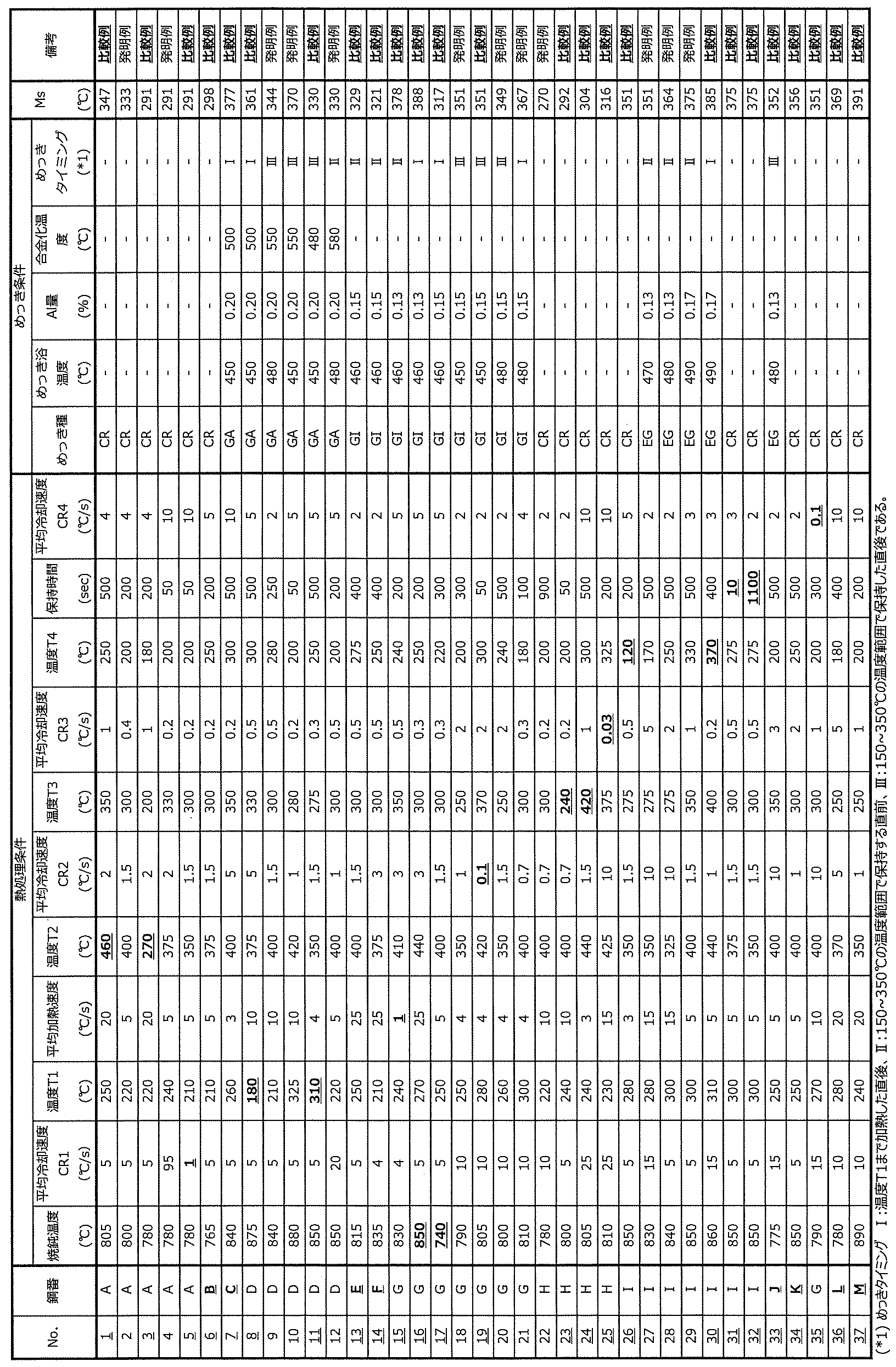
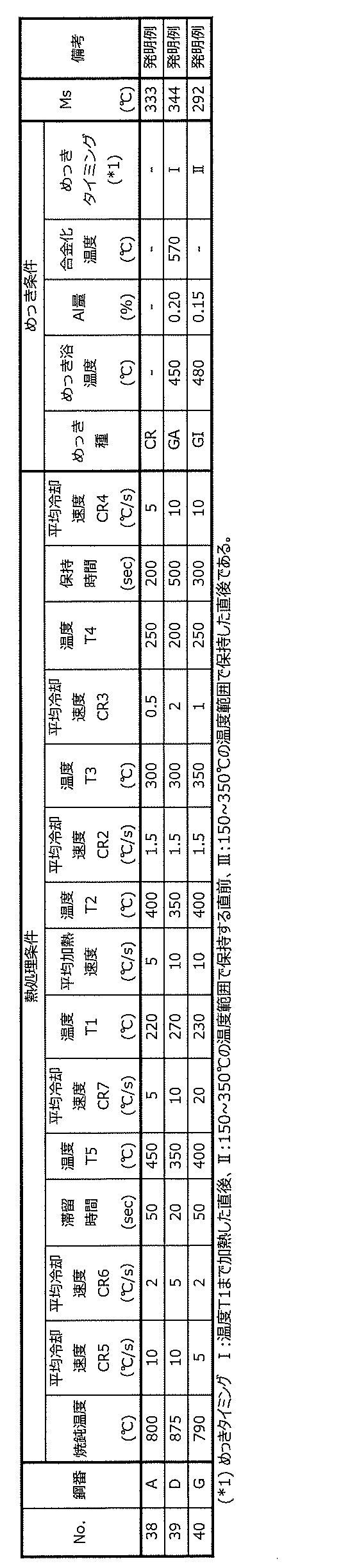
得られた鋼板より、JIS5号引張試験片および穴広げ試験片を採取し、引張試験(JIS Z2241(2011)に準拠)を実施した。引張強度TS、均一伸びU-Elを表4と表5に示す。
引張強度が780MPa以上であるものを強度に優れると判断した。
また、均一伸びU-Elは、TS:980MPa未満では16.0%以上、TS:980MPa以上1180MPa未満では11.0%以上、TS:1180MPa以上では8.0%以上のものを延性に優れると判断した。
伸びフランジ成形性は日本鉄鋼連盟規格JFST1001の規定に準拠した穴広げ試験により評価した。すなわち、100mm×100mm角サイズのサンプルにポンチ径10mm、ダイス径10.3mm(クリアランス13%)の打ち抜き工具を用いて打ち抜き後、頂角60度の円錐ポンチを用いて、打ち抜き穴形成の際に発生したバリが外側になるようにして、板厚を貫通する割れが発生するまで穴広げを行った。この際のd0:初期穴径(mm)、d:割れ発生時の穴径(mm)として、穴広げ率λ(%)={(d-d0)/d0}×100として求めた。穴広げ率λを表4と表5に示す。
30%以上のλを有する鋼板を伸びフランジ性に優れると判断した。
図3は、VDA曲げ角度の算出方法を説明するための図である。
図3に示すように、軸圧壊特性の評価として、VDA曲げ角度αは、ドイツ自動車工業会で規定されたVDA規格(VDA238-100)に準拠した曲げ試験(Verband der Automobilindustrie:VDA曲げ試験)により評価した。VDA曲げ試験とは、ドイツ自動車工業会で規定されたVDA規格(VDA238-100)に準拠した曲げ試験(Verband der Automobilindustrie:VDA曲げ試験)を表し、非常に狭い間隔のロール10と鋭利なポンチ11を特徴とする3点板曲げ試験である。VDA曲げ試験には60mm×60mm角の試験片を用い、曲げ稜線方向を圧延方向と平行とし、ロール径Dが30mm、ロール間距離L(図示せず)が(板厚a0×2)+0.5mmのロールで支持し、上から先端r(曲率半径)が0.4mmのポンチでストローク速度20mm/minで押し込むことによって行った(図中、符号11Aが押し込み前のポンチを示し、符号11Bが押し込み後のポンチを示す。)。
なお、図3においては、説明上、押し込み軸を中心に線対称に図示できる試験片(鋼板XA、XB)、ロール10のうち、一方側のみ図示している。
VDA曲げ角度αとは、前記曲げ試験における最大荷重時のストロークS(mm)より式(1)~(5)を用いて算出される曲げ角度(°)であり、軸圧壊特性の指標として用いることができる。
αが70°以上の鋼板を軸圧壊特性に優れると判断した。



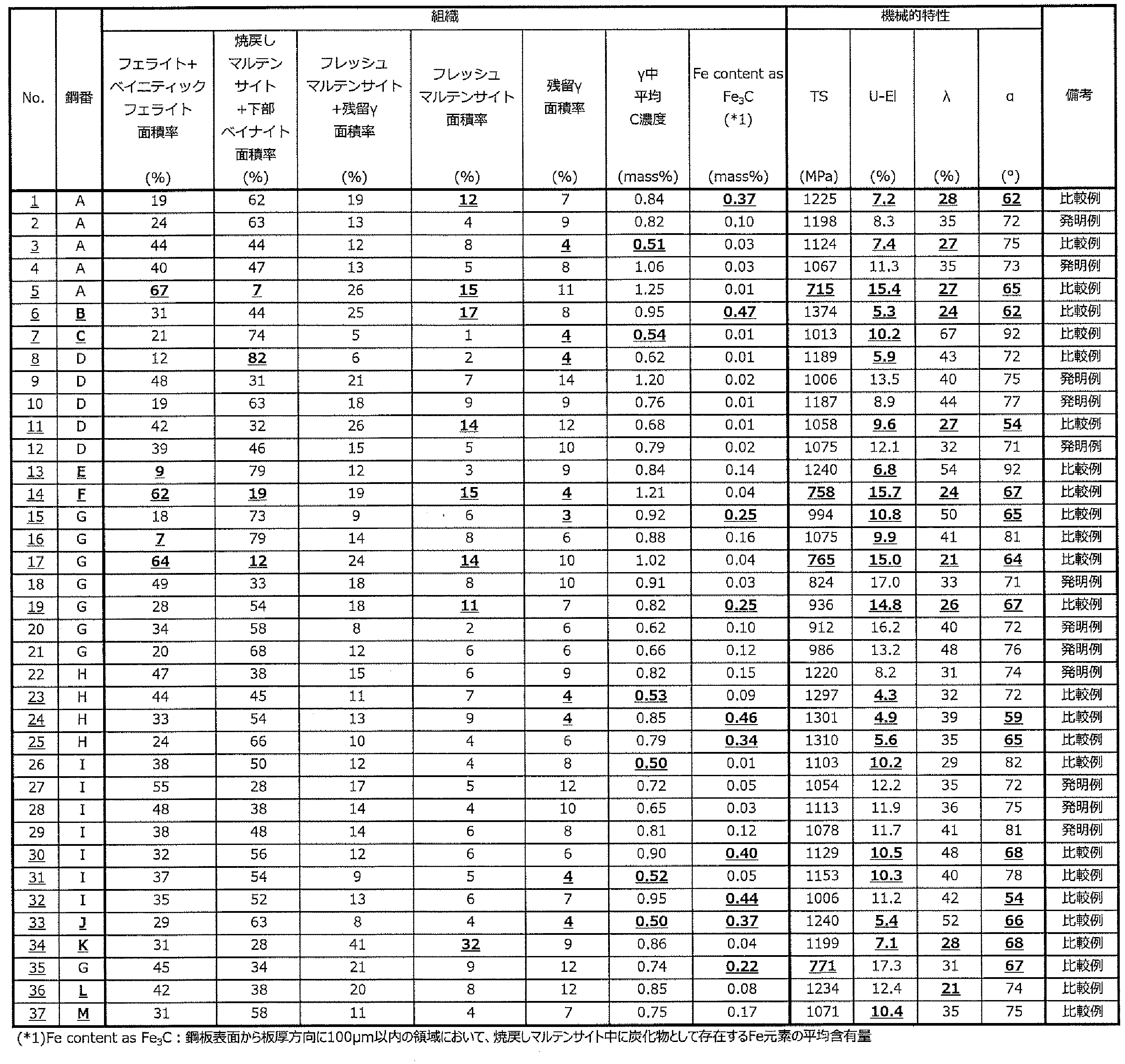

BF ベイニティックフェライト
TM 焼戻しマルテンサイト
FM フレッシュマルテンサイト
RA 残留オーステナイト
α VDA曲げ角度
10 ロール
D ロール径
11 ポンチ
11A 押し込み前のポンチ
11B 押し込み後のポンチ
S ストローク
r 先端の曲率半径
XA 押し込み前の鋼板
XB 押し込み後の鋼板
a0 板厚
Claims (10)
- 質量%で、
C:0.10%以上0.30%以下、
Si:0.5%以上2.0%以下、
Mn:1.5%以上3.0%以下、
P:0.10%以下、
S:0.020%以下、
sol.Al:1.00%以下、
N:0.015%以下
を含有し、残部Feおよび不可避的不純物からなる成分組成を有し、
面積率で、
フェライトおよびベイニティックフェライトのうちの1種以上からなる組織:10%以上60%以下、
焼戻しマルテンサイトおよび下部ベイナイトのうちの1種以上からなる組織:20%以上80%以下、
残留オーステナイト:5%以上、
フレッシュマルテンサイト:10%以下
を含有する鋼組織を有し、
前記残留オーステナイト中の平均C濃度が0.60mass%以上であり、
鋼板表面から板厚方向に100μm以内の領域において、焼戻しマルテンサイト中に炭化物として存在するFe元素の含有量が平均で0.20mass%以下である、鋼板。 - 前記成分組成は、さらに、質量%で、
Ti:0.100%以下、
Nb:0.100%以下、
V:0.100%以下、
B:0.0050%以下、
Cr:1.000%以下、
Cu:1.000%以下、
Sb:0.200%以下、
Sn:0.200%以下、
Ta:0.100%以下、
Ca:0.0050%以下、
Mg:0.0050%以下、
REM:0.0050%以下
のうちから選ばれる少なくとも1種以上の元素を含有する、請求項1に記載の鋼板。 - 鋼板表面に亜鉛めっき層を有する、請求項1または2に記載の鋼板。
- 請求項1~3のいずれかに記載の鋼板を用いてなる部材。
- 請求項1または2に記載の成分組成を有する鋼スラブに対して、熱間圧延および冷間圧延を行った後、得られた冷延鋼板に対して、
焼鈍温度:750℃以上Ac3温度(℃)以下で焼鈍処理を施した後、
前記焼鈍温度から、200℃以上かつ(Ms点(℃)-30℃)以下の温度T1までの範囲を平均冷却速度CR1:3℃/s以上100℃/s以下で冷却し、
前記温度T1から、300℃以上450℃以下の温度T2までの温度範囲を平均加熱速度2℃/s以上で加熱し、
前記温度T2から、(T2-150℃)以上(T2-30℃)以下の温度T3までの温度範囲を平均冷却速度CR2:0.5℃/s以上で冷却し、
前記温度T3から、150℃以上350℃以下かつ前記温度T3以下の温度T4までの温度範囲を平均冷却速度CR3:0.1℃/s以上で冷却し、
150℃以上350℃以下かつ前記温度T4以下の温度範囲で20s以上1000s以下保持し、
50℃以下の温度まで平均冷却速度CR4:1℃/s以上で冷却する、鋼板の製造方法。 - 請求項1または2に記載の成分組成を有する鋼スラブに対して、熱間圧延および冷間圧延を行った後、得られた冷延鋼板に対して、
焼鈍温度:750℃以上Ac3温度(℃)以下で焼鈍処理を施した後、
前記焼鈍温度から、500℃までの温度範囲を平均冷却速度CR5:5℃/s以上100℃/s以下で冷却し、
500℃から、Ms点(℃)以上かつ320℃以上の滞留停止温度T5までの温度範囲を平均冷却速度CR6:10℃/s以下で10s以上60s以下滞留させ、
前記滞留停止温度T5から、200℃以上かつ(Ms点(℃)-30℃)以下の温度T1までの温度範囲を平均冷却速度CR7:3℃/s以上100℃/s以下で冷却し、
前記温度T1から、300℃以上450℃以下の温度T2までの温度範囲を平均加熱速度2℃/s以上で加熱し、
前記温度T2から、(T2-150℃)以上(T2-30℃)以下の温度T3までの温度範囲を平均冷却速度CR2:0.5℃/s以上で冷却し、
前記温度T3から、150℃以上350℃以下かつ前記温度T3以下の温度T4までの温度範囲を平均冷却速度CR3:0.1℃/s以上で冷却し、
150℃以上350℃以下かつ前記温度T4以下の温度範囲で20s以上1000s以下保持し、
50℃以下の温度まで平均冷却速度CR4:1℃/s以上で冷却する、鋼板の製造方法。 - 前記平均冷却速度CR1:3℃/s以上100℃/s以下で冷却した後に、鋼板に溶融亜鉛めっき処理または合金化溶融亜鉛めっき処理を行う、請求項5に記載の鋼板の製造方法。
- 前記平均冷却速度CR7:3℃/s以上100℃/s以下で冷却した後に、鋼板に溶融亜鉛めっき処理または合金化溶融亜鉛めっき処理を行う、請求項6に記載の鋼板の製造方法。
- 前記平均冷却速度CR4:1℃/s以上で冷却した後に、鋼板に電気亜鉛めっき処理を行う、請求項5または6に記載の鋼板の製造方法。
- 請求項1~3のいずれかに記載の鋼板に、成形加工、接合加工の少なくとも一方を施して部材とする工程を含む、部材の製造方法。
Priority Applications (5)
| Application Number | Priority Date | Filing Date | Title |
|---|---|---|---|
| CN202480020355.9A CN120936735A (zh) | 2023-03-31 | 2024-03-14 | 钢板、构件和它们的制造方法 |
| JP2024542204A JP7635896B1 (ja) | 2023-03-31 | 2024-03-14 | 鋼板、部材およびそれらの製造方法 |
| EP24779540.4A EP4660347A1 (en) | 2023-03-31 | 2024-03-14 | Steel sheet, member, and method for manufacturing same |
| KR1020257031251A KR20250150126A (ko) | 2023-03-31 | 2024-03-14 | 강판, 부재 및 그들의 제조 방법 |
| MX2025011271A MX2025011271A (es) | 2023-03-31 | 2025-09-23 | Lamina de acero, miembro, y metodos para producir los mismos |
Applications Claiming Priority (2)
| Application Number | Priority Date | Filing Date | Title |
|---|---|---|---|
| JP2023058444 | 2023-03-31 | ||
| JP2023-058444 | 2023-03-31 |
Publications (1)
| Publication Number | Publication Date |
|---|---|
| WO2024203411A1 true WO2024203411A1 (ja) | 2024-10-03 |
Family
ID=92904687
Family Applications (1)
| Application Number | Title | Priority Date | Filing Date |
|---|---|---|---|
| PCT/JP2024/010116 Ceased WO2024203411A1 (ja) | 2023-03-31 | 2024-03-14 | 鋼板、部材およびそれらの製造方法 |
Country Status (6)
| Country | Link |
|---|---|
| EP (1) | EP4660347A1 (ja) |
| JP (1) | JP7635896B1 (ja) |
| KR (1) | KR20250150126A (ja) |
| CN (1) | CN120936735A (ja) |
| MX (1) | MX2025011271A (ja) |
| WO (1) | WO2024203411A1 (ja) |
Citations (7)
| Publication number | Priority date | Publication date | Assignee | Title |
|---|---|---|---|---|
| JP2007211280A (ja) * | 2006-02-08 | 2007-08-23 | Nippon Steel Corp | 成形性と穴拡げ性に優れた高強度溶融亜鉛めっき鋼板と高強度合金化溶融亜鉛めっき鋼板及び高強度溶融亜鉛めっき鋼板の製造方法並びに高強度合金化溶融亜鉛めっき鋼板の製造方法 |
| JP2017507241A (ja) * | 2013-12-11 | 2017-03-16 | アルセロールミタル | 高強度鋼および製造方法 |
| JP2019505691A (ja) * | 2015-12-21 | 2019-02-28 | アルセロールミタル | 改善された延性及び成形加工性を有する高強度鋼板を製造するための方法並びに得られた鋼板 |
| WO2019186997A1 (ja) * | 2018-03-30 | 2019-10-03 | 日本製鉄株式会社 | 鋼板およびその製造方法 |
| WO2022004818A1 (ja) * | 2020-06-30 | 2022-01-06 | Jfeスチール株式会社 | 鋼板、部材及びそれらの製造方法 |
| WO2022004820A1 (ja) * | 2020-06-30 | 2022-01-06 | Jfeスチール株式会社 | 亜鉛めっき鋼板、部材及びそれらの製造方法 |
| WO2022004817A1 (ja) * | 2020-06-30 | 2022-01-06 | Jfeスチール株式会社 | 鋼板、部材及びそれらの製造方法 |
Family Cites Families (3)
| Publication number | Priority date | Publication date | Assignee | Title |
|---|---|---|---|---|
| CN102712980B (zh) | 2010-01-26 | 2014-07-02 | 新日铁住金株式会社 | 高强度冷轧钢板及其制造方法 |
| CN111344423B (zh) | 2017-11-15 | 2022-07-22 | 日本制铁株式会社 | 高强度冷轧钢板 |
| EP3901293B1 (en) | 2019-01-29 | 2024-03-20 | JFE Steel Corporation | High-strength hot-dip galvanized steel sheet and manufacturing method therefor |
-
2024
- 2024-03-14 KR KR1020257031251A patent/KR20250150126A/ko active Pending
- 2024-03-14 WO PCT/JP2024/010116 patent/WO2024203411A1/ja not_active Ceased
- 2024-03-14 CN CN202480020355.9A patent/CN120936735A/zh active Pending
- 2024-03-14 EP EP24779540.4A patent/EP4660347A1/en active Pending
- 2024-03-14 JP JP2024542204A patent/JP7635896B1/ja active Active
-
2025
- 2025-09-23 MX MX2025011271A patent/MX2025011271A/es unknown
Patent Citations (7)
| Publication number | Priority date | Publication date | Assignee | Title |
|---|---|---|---|---|
| JP2007211280A (ja) * | 2006-02-08 | 2007-08-23 | Nippon Steel Corp | 成形性と穴拡げ性に優れた高強度溶融亜鉛めっき鋼板と高強度合金化溶融亜鉛めっき鋼板及び高強度溶融亜鉛めっき鋼板の製造方法並びに高強度合金化溶融亜鉛めっき鋼板の製造方法 |
| JP2017507241A (ja) * | 2013-12-11 | 2017-03-16 | アルセロールミタル | 高強度鋼および製造方法 |
| JP2019505691A (ja) * | 2015-12-21 | 2019-02-28 | アルセロールミタル | 改善された延性及び成形加工性を有する高強度鋼板を製造するための方法並びに得られた鋼板 |
| WO2019186997A1 (ja) * | 2018-03-30 | 2019-10-03 | 日本製鉄株式会社 | 鋼板およびその製造方法 |
| WO2022004818A1 (ja) * | 2020-06-30 | 2022-01-06 | Jfeスチール株式会社 | 鋼板、部材及びそれらの製造方法 |
| WO2022004820A1 (ja) * | 2020-06-30 | 2022-01-06 | Jfeスチール株式会社 | 亜鉛めっき鋼板、部材及びそれらの製造方法 |
| WO2022004817A1 (ja) * | 2020-06-30 | 2022-01-06 | Jfeスチール株式会社 | 鋼板、部材及びそれらの製造方法 |
Non-Patent Citations (1)
| Title |
|---|
| See also references of EP4660347A1 * |
Also Published As
| Publication number | Publication date |
|---|---|
| EP4660347A1 (en) | 2025-12-10 |
| KR20250150126A (ko) | 2025-10-17 |
| MX2025011271A (es) | 2025-10-01 |
| JP7635896B1 (ja) | 2025-02-26 |
| JPWO2024203411A1 (ja) | 2024-10-03 |
| CN120936735A (zh) | 2025-11-11 |
Similar Documents
| Publication | Publication Date | Title |
|---|---|---|
| US11939640B2 (en) | Method for producing hot-rolled steel sheet, method for producing cold-rolled full-hard steel sheet, and method for producing heat-treated sheet | |
| US10745775B2 (en) | Galvannealed steel sheet and method for producing the same | |
| JP6544494B1 (ja) | 高強度亜鉛めっき鋼板およびその製造方法 | |
| EP3543364B1 (en) | High-strength steel sheet and method for producing same | |
| EP3543365B1 (en) | High-strength steel sheet and method for producing same | |
| CN114555845B (zh) | 高强度钢板及其制造方法 | |
| WO2016067623A1 (ja) | 高強度鋼板、高強度溶融亜鉛めっき鋼板、高強度溶融アルミニウムめっき鋼板および高強度電気亜鉛めっき鋼板、ならびに、それらの製造方法 | |
| CN114981457A (zh) | 高强度镀锌钢板及其制造方法 | |
| CN114585765B (zh) | 高强度钢板及其制造方法 | |
| CN114585766A (zh) | 高强度钢板及其制造方法 | |
| CN113544299A (zh) | 高强度钢板及其制造方法 | |
| CN108713066B (zh) | 高强度钢板及其制造方法 | |
| CN116806274B (zh) | 高强度钢板及其制造方法 | |
| JP7655449B2 (ja) | 鋼板、部材およびそれらの製造方法 | |
| JP7635896B1 (ja) | 鋼板、部材およびそれらの製造方法 | |
| JP7635895B1 (ja) | 鋼板、部材およびそれらの製造方法 | |
| JP7417169B2 (ja) | 鋼板およびその製造方法 | |
| CN114585758B (zh) | 高强度钢板和碰撞吸收构件以及高强度钢板的制造方法 | |
| JP7655450B2 (ja) | 鋼板、部材およびそれらの製造方法 | |
| CN114375343A (zh) | 高强度钢板及其制造方法 | |
| EP4640883A1 (en) | Cold-rolled steel sheet and manufacturing method therefor | |
| WO2025142033A1 (ja) | 鋼板、部材およびそれらの製造方法 | |
| CN120569504A (zh) | 冷轧钢板及其制造方法 | |
| CN116897217A (zh) | 钢板、构件和它们的制造方法 |
Legal Events
| Date | Code | Title | Description |
|---|---|---|---|
| WWE | Wipo information: entry into national phase |
Ref document number: 2024542204 Country of ref document: JP |
|
| 121 | Ep: the epo has been informed by wipo that ep was designated in this application |
Ref document number: 24779540 Country of ref document: EP Kind code of ref document: A1 |
|
| WWE | Wipo information: entry into national phase |
Ref document number: 202517082877 Country of ref document: IN |
|
| ENP | Entry into the national phase |
Ref document number: 1020257031251 Country of ref document: KR Free format text: ST27 STATUS EVENT CODE: A-0-1-A10-A15-NAP-PA0105 (AS PROVIDED BY THE NATIONAL OFFICE) |
|
| WWE | Wipo information: entry into national phase |
Ref document number: 2501006248 Country of ref document: TH |
|
| WWP | Wipo information: published in national office |
Ref document number: 202517082877 Country of ref document: IN |
|
| WWP | Wipo information: published in national office |
Ref document number: 1020257031251 Country of ref document: KR |
|
| NENP | Non-entry into the national phase |
Ref country code: DE |
|
| WWP | Wipo information: published in national office |
Ref document number: 2024779540 Country of ref document: EP |