WO2024203606A1 - 鋼板および鋼板の製造方法 - Google Patents
鋼板および鋼板の製造方法 Download PDFInfo
- Publication number
- WO2024203606A1 WO2024203606A1 PCT/JP2024/010716 JP2024010716W WO2024203606A1 WO 2024203606 A1 WO2024203606 A1 WO 2024203606A1 JP 2024010716 W JP2024010716 W JP 2024010716W WO 2024203606 A1 WO2024203606 A1 WO 2024203606A1
- Authority
- WO
- WIPO (PCT)
- Prior art keywords
- mass
- less
- steel sheet
- carbon concentration
- steel plate
- Prior art date
- Legal status (The legal status is an assumption and is not a legal conclusion. Google has not performed a legal analysis and makes no representation as to the accuracy of the status listed.)
- Ceased
Links
Images


Classifications
-
- C—CHEMISTRY; METALLURGY
- C21—METALLURGY OF IRON
- C21D—MODIFYING THE PHYSICAL STRUCTURE OF FERROUS METALS; GENERAL DEVICES FOR HEAT TREATMENT OF FERROUS OR NON-FERROUS METALS OR ALLOYS; MAKING METAL MALLEABLE, e.g. BY DECARBURISATION OR TEMPERING
- C21D9/00—Heat treatment, e.g. annealing, hardening, quenching or tempering, adapted for particular articles; Furnaces therefor
- C21D9/46—Heat treatment, e.g. annealing, hardening, quenching or tempering, adapted for particular articles; Furnaces therefor for sheet metals
-
- B—PERFORMING OPERATIONS; TRANSPORTING
- B32—LAYERED PRODUCTS
- B32B—LAYERED PRODUCTS, i.e. PRODUCTS BUILT-UP OF STRATA OF FLAT OR NON-FLAT, e.g. CELLULAR OR HONEYCOMB, FORM
- B32B15/00—Layered products comprising a layer of metal
- B32B15/01—Layered products comprising a layer of metal all layers being exclusively metallic
- B32B15/013—Layered products comprising a layer of metal all layers being exclusively metallic one layer being formed of an iron alloy or steel, another layer being formed of a metal other than iron or aluminium
-
- C—CHEMISTRY; METALLURGY
- C21—METALLURGY OF IRON
- C21D—MODIFYING THE PHYSICAL STRUCTURE OF FERROUS METALS; GENERAL DEVICES FOR HEAT TREATMENT OF FERROUS OR NON-FERROUS METALS OR ALLOYS; MAKING METAL MALLEABLE, e.g. BY DECARBURISATION OR TEMPERING
- C21D1/00—General methods or devices for heat treatment, e.g. annealing, hardening, quenching or tempering
- C21D1/74—Methods of treatment in inert gas, controlled atmosphere, vacuum or pulverulent material
- C21D1/76—Adjusting the composition of the atmosphere
-
- C—CHEMISTRY; METALLURGY
- C21—METALLURGY OF IRON
- C21D—MODIFYING THE PHYSICAL STRUCTURE OF FERROUS METALS; GENERAL DEVICES FOR HEAT TREATMENT OF FERROUS OR NON-FERROUS METALS OR ALLOYS; MAKING METAL MALLEABLE, e.g. BY DECARBURISATION OR TEMPERING
- C21D3/00—Diffusion processes for extraction of non-metals; Furnaces therefor
- C21D3/02—Extraction of non-metals
- C21D3/04—Decarburising
-
- C—CHEMISTRY; METALLURGY
- C21—METALLURGY OF IRON
- C21D—MODIFYING THE PHYSICAL STRUCTURE OF FERROUS METALS; GENERAL DEVICES FOR HEAT TREATMENT OF FERROUS OR NON-FERROUS METALS OR ALLOYS; MAKING METAL MALLEABLE, e.g. BY DECARBURISATION OR TEMPERING
- C21D8/00—Modifying the physical properties of ferrous metals or ferrous alloys by deformation combined with, or followed by, heat treatment
- C21D8/02—Modifying the physical properties of ferrous metals or ferrous alloys by deformation combined with, or followed by, heat treatment during manufacturing of plates or strips
- C21D8/0247—Modifying the physical properties of ferrous metals or ferrous alloys by deformation combined with, or followed by, heat treatment during manufacturing of plates or strips characterised by the heat treatment
- C21D8/0273—Final recrystallisation annealing
-
- C—CHEMISTRY; METALLURGY
- C22—METALLURGY; FERROUS OR NON-FERROUS ALLOYS; TREATMENT OF ALLOYS OR NON-FERROUS METALS
- C22C—ALLOYS
- C22C38/00—Ferrous alloys, e.g. steel alloys
- C22C38/001—Ferrous alloys, e.g. steel alloys containing N
-
- C—CHEMISTRY; METALLURGY
- C22—METALLURGY; FERROUS OR NON-FERROUS ALLOYS; TREATMENT OF ALLOYS OR NON-FERROUS METALS
- C22C—ALLOYS
- C22C38/00—Ferrous alloys, e.g. steel alloys
- C22C38/002—Ferrous alloys, e.g. steel alloys containing In, Mg, or other elements not provided for in one single group C22C38/001 - C22C38/60
-
- C—CHEMISTRY; METALLURGY
- C22—METALLURGY; FERROUS OR NON-FERROUS ALLOYS; TREATMENT OF ALLOYS OR NON-FERROUS METALS
- C22C—ALLOYS
- C22C38/00—Ferrous alloys, e.g. steel alloys
- C22C38/02—Ferrous alloys, e.g. steel alloys containing silicon
-
- C—CHEMISTRY; METALLURGY
- C22—METALLURGY; FERROUS OR NON-FERROUS ALLOYS; TREATMENT OF ALLOYS OR NON-FERROUS METALS
- C22C—ALLOYS
- C22C38/00—Ferrous alloys, e.g. steel alloys
- C22C38/04—Ferrous alloys, e.g. steel alloys containing manganese
-
- C—CHEMISTRY; METALLURGY
- C22—METALLURGY; FERROUS OR NON-FERROUS ALLOYS; TREATMENT OF ALLOYS OR NON-FERROUS METALS
- C22C—ALLOYS
- C22C38/00—Ferrous alloys, e.g. steel alloys
- C22C38/06—Ferrous alloys, e.g. steel alloys containing aluminium
-
- C—CHEMISTRY; METALLURGY
- C22—METALLURGY; FERROUS OR NON-FERROUS ALLOYS; TREATMENT OF ALLOYS OR NON-FERROUS METALS
- C22C—ALLOYS
- C22C38/00—Ferrous alloys, e.g. steel alloys
- C22C38/08—Ferrous alloys, e.g. steel alloys containing nickel
-
- C—CHEMISTRY; METALLURGY
- C22—METALLURGY; FERROUS OR NON-FERROUS ALLOYS; TREATMENT OF ALLOYS OR NON-FERROUS METALS
- C22C—ALLOYS
- C22C38/00—Ferrous alloys, e.g. steel alloys
- C22C38/12—Ferrous alloys, e.g. steel alloys containing tungsten, tantalum, molybdenum, vanadium, or niobium
-
- C—CHEMISTRY; METALLURGY
- C22—METALLURGY; FERROUS OR NON-FERROUS ALLOYS; TREATMENT OF ALLOYS OR NON-FERROUS METALS
- C22C—ALLOYS
- C22C38/00—Ferrous alloys, e.g. steel alloys
- C22C38/14—Ferrous alloys, e.g. steel alloys containing titanium or zirconium
-
- C—CHEMISTRY; METALLURGY
- C22—METALLURGY; FERROUS OR NON-FERROUS ALLOYS; TREATMENT OF ALLOYS OR NON-FERROUS METALS
- C22C—ALLOYS
- C22C38/00—Ferrous alloys, e.g. steel alloys
- C22C38/16—Ferrous alloys, e.g. steel alloys containing copper
-
- C—CHEMISTRY; METALLURGY
- C22—METALLURGY; FERROUS OR NON-FERROUS ALLOYS; TREATMENT OF ALLOYS OR NON-FERROUS METALS
- C22C—ALLOYS
- C22C38/00—Ferrous alloys, e.g. steel alloys
- C22C38/18—Ferrous alloys, e.g. steel alloys containing chromium
- C22C38/32—Ferrous alloys, e.g. steel alloys containing chromium with boron
-
- C—CHEMISTRY; METALLURGY
- C22—METALLURGY; FERROUS OR NON-FERROUS ALLOYS; TREATMENT OF ALLOYS OR NON-FERROUS METALS
- C22C—ALLOYS
- C22C38/00—Ferrous alloys, e.g. steel alloys
- C22C38/18—Ferrous alloys, e.g. steel alloys containing chromium
- C22C38/34—Ferrous alloys, e.g. steel alloys containing chromium with more than 1.5% by weight of silicon
-
- C—CHEMISTRY; METALLURGY
- C22—METALLURGY; FERROUS OR NON-FERROUS ALLOYS; TREATMENT OF ALLOYS OR NON-FERROUS METALS
- C22C—ALLOYS
- C22C38/00—Ferrous alloys, e.g. steel alloys
- C22C38/18—Ferrous alloys, e.g. steel alloys containing chromium
- C22C38/38—Ferrous alloys, e.g. steel alloys containing chromium with more than 1.5% by weight of manganese
-
- C—CHEMISTRY; METALLURGY
- C23—COATING METALLIC MATERIAL; COATING MATERIAL WITH METALLIC MATERIAL; CHEMICAL SURFACE TREATMENT; DIFFUSION TREATMENT OF METALLIC MATERIAL; COATING BY VACUUM EVAPORATION, BY SPUTTERING, BY ION IMPLANTATION OR BY CHEMICAL VAPOUR DEPOSITION, IN GENERAL; INHIBITING CORROSION OF METALLIC MATERIAL OR INCRUSTATION IN GENERAL
- C23C—COATING METALLIC MATERIAL; COATING MATERIAL WITH METALLIC MATERIAL; SURFACE TREATMENT OF METALLIC MATERIAL BY DIFFUSION INTO THE SURFACE, BY CHEMICAL CONVERSION OR SUBSTITUTION; COATING BY VACUUM EVAPORATION, BY SPUTTERING, BY ION IMPLANTATION OR BY CHEMICAL VAPOUR DEPOSITION, IN GENERAL
- C23C2/00—Hot-dipping or immersion processes for applying the coating material in the molten state without affecting the shape; Apparatus therefor
- C23C2/02—Pretreatment of the material to be coated, e.g. for coating on selected surface areas
- C23C2/022—Pretreatment of the material to be coated, e.g. for coating on selected surface areas by heating
- C23C2/0224—Two or more thermal pretreatments
-
- C—CHEMISTRY; METALLURGY
- C23—COATING METALLIC MATERIAL; COATING MATERIAL WITH METALLIC MATERIAL; CHEMICAL SURFACE TREATMENT; DIFFUSION TREATMENT OF METALLIC MATERIAL; COATING BY VACUUM EVAPORATION, BY SPUTTERING, BY ION IMPLANTATION OR BY CHEMICAL VAPOUR DEPOSITION, IN GENERAL; INHIBITING CORROSION OF METALLIC MATERIAL OR INCRUSTATION IN GENERAL
- C23C—COATING METALLIC MATERIAL; COATING MATERIAL WITH METALLIC MATERIAL; SURFACE TREATMENT OF METALLIC MATERIAL BY DIFFUSION INTO THE SURFACE, BY CHEMICAL CONVERSION OR SUBSTITUTION; COATING BY VACUUM EVAPORATION, BY SPUTTERING, BY ION IMPLANTATION OR BY CHEMICAL VAPOUR DEPOSITION, IN GENERAL
- C23C2/00—Hot-dipping or immersion processes for applying the coating material in the molten state without affecting the shape; Apparatus therefor
- C23C2/04—Hot-dipping or immersion processes for applying the coating material in the molten state without affecting the shape; Apparatus therefor characterised by the coating material
- C23C2/06—Zinc or cadmium or alloys based thereon
-
- C—CHEMISTRY; METALLURGY
- C23—COATING METALLIC MATERIAL; COATING MATERIAL WITH METALLIC MATERIAL; CHEMICAL SURFACE TREATMENT; DIFFUSION TREATMENT OF METALLIC MATERIAL; COATING BY VACUUM EVAPORATION, BY SPUTTERING, BY ION IMPLANTATION OR BY CHEMICAL VAPOUR DEPOSITION, IN GENERAL; INHIBITING CORROSION OF METALLIC MATERIAL OR INCRUSTATION IN GENERAL
- C23C—COATING METALLIC MATERIAL; COATING MATERIAL WITH METALLIC MATERIAL; SURFACE TREATMENT OF METALLIC MATERIAL BY DIFFUSION INTO THE SURFACE, BY CHEMICAL CONVERSION OR SUBSTITUTION; COATING BY VACUUM EVAPORATION, BY SPUTTERING, BY ION IMPLANTATION OR BY CHEMICAL VAPOUR DEPOSITION, IN GENERAL
- C23C2/00—Hot-dipping or immersion processes for applying the coating material in the molten state without affecting the shape; Apparatus therefor
- C23C2/04—Hot-dipping or immersion processes for applying the coating material in the molten state without affecting the shape; Apparatus therefor characterised by the coating material
- C23C2/12—Aluminium or alloys based thereon
-
- C—CHEMISTRY; METALLURGY
- C23—COATING METALLIC MATERIAL; COATING MATERIAL WITH METALLIC MATERIAL; CHEMICAL SURFACE TREATMENT; DIFFUSION TREATMENT OF METALLIC MATERIAL; COATING BY VACUUM EVAPORATION, BY SPUTTERING, BY ION IMPLANTATION OR BY CHEMICAL VAPOUR DEPOSITION, IN GENERAL; INHIBITING CORROSION OF METALLIC MATERIAL OR INCRUSTATION IN GENERAL
- C23C—COATING METALLIC MATERIAL; COATING MATERIAL WITH METALLIC MATERIAL; SURFACE TREATMENT OF METALLIC MATERIAL BY DIFFUSION INTO THE SURFACE, BY CHEMICAL CONVERSION OR SUBSTITUTION; COATING BY VACUUM EVAPORATION, BY SPUTTERING, BY ION IMPLANTATION OR BY CHEMICAL VAPOUR DEPOSITION, IN GENERAL
- C23C2/00—Hot-dipping or immersion processes for applying the coating material in the molten state without affecting the shape; Apparatus therefor
- C23C2/26—After-treatment
- C23C2/28—Thermal after-treatment, e.g. treatment in oil bath
-
- C—CHEMISTRY; METALLURGY
- C21—METALLURGY OF IRON
- C21D—MODIFYING THE PHYSICAL STRUCTURE OF FERROUS METALS; GENERAL DEVICES FOR HEAT TREATMENT OF FERROUS OR NON-FERROUS METALS OR ALLOYS; MAKING METAL MALLEABLE, e.g. BY DECARBURISATION OR TEMPERING
- C21D2211/00—Microstructure comprising significant phases
- C21D2211/004—Dispersions; Precipitations
Definitions
- This disclosure relates to steel plates and methods for manufacturing steel plates.
- it relates to high-tensile steel plates with excellent bendability and methods for manufacturing steel plates.
- Si and Mn is effective in increasing the strength of steel sheets to achieve vehicle weight reduction.
- Si and Mn oxidize even in a reducing atmosphere in which Fe does not oxidize, and oxides of Si and Mn are formed on the outermost surface of the steel sheet.
- oxides of Si and Mn reduce the wettability of the molten zinc with the base steel sheet, so steel sheets to which Si and Mn have been added have problems such as frequent bare spots and poor plating adhesion.
- Patent Document 1 discloses a method for producing a high-strength hot-dip galvanized steel sheet having excellent coating adhesion, workability, and fatigue resistance, which comprises the steps of: in a first step, heating the steel sheet at a temperature of 400 to 750°C in an atmosphere having an O2 concentration of 1000 ppm by volume or more and an H2O concentration of 1000 ppm by volume or more; and in a second step, heating at a temperature of 600 to 850° C in an atmosphere having an O2 concentration of less than 1000 ppm by volume and an H2O concentration of 1000 ppm by volume or more; in a heating zone, heating to a temperature of 650 to 900°C at a heating rate of 0.1°C/sec or more in an atmosphere having an H2 concentration of 5 to 30% by volume, an H2O concentration of 10 to 1000 ppm by volume, and the remainder consisting of N2 and unavoidable impurities; It is shown that reduction annealing is performed in an atmosphere having an atmosphere having an atmosphere having an
- Patent Document 1 does not consider improving the bendability of plated steel sheets. This disclosure has been made in consideration of the above circumstances, and its purpose is to provide a steel sheet that is high-strength, can contribute to reducing the weight of the vehicle body, and exhibits excellent bendability, and a method for easily manufacturing the steel sheet.
- Aspect 1 of the present invention is In the plate thickness direction, This steel plate has a position where the carbon concentration (mass %) is 50% of the bulk carbon concentration in a region that is 0.20% or more of the plate thickness from the steel plate surface, and a position where the carbon concentration (mass %) is 90% of the bulk carbon concentration in a region that is 8.0% or less of the plate thickness from the steel plate surface.
- Aspect 2 of the present invention is The steel sheet according to aspect 1, wherein the maximum carbon concentration (mass%) in a region from the steel sheet surface to 20 ⁇ m in the sheet thickness direction is less than 70% of the bulk carbon concentration, and the amount of surface decarburization per mm of sheet thickness on one side of the steel sheet is 0.045 mol/ m2 or less.
- Aspect 3 of the present invention is 3.
- Aspect 4 of the present invention is The composition of the components is C: 0.08% by mass or more, 0.30% by mass or less, Si: more than 0.5 mass%, 3.0 mass% or less, Mn: 1.5% by mass or more, 3.0% by mass or less, Cr: 0 mass% or more, 1.0 mass% or less, P: more than 0 mass%, 0.1 mass% or less, S: more than 0 mass%, 0.05 mass% or less, Al: more than 0 mass% and 1.0 mass% or less; and N: more than 0 mass% and 0.01 mass% or less;
- the steel sheet according to any one of Aspects 1 to 3, wherein the balance is Fe and unavoidable impurities.
- the annealing process includes an oxidizing process under conditions of an oxygen concentration of 0.1 to 2% and an ultimate temperature of 650 to 750°C, followed by a reducing process.
- the reduction treatment is a method for producing a steel sheet, which includes a first reduction treatment having a dew point of ⁇ 35 to ⁇ 15° C., followed by a second reduction treatment having a dew point of ⁇ 25 to 0° C., which is higher than that of the first reduction treatment.
- Aspect 6 of the present invention is A method for producing a steel sheet according to aspect 5, wherein an ultimate temperature in the first reduction treatment and the second reduction treatment is 800 to 920°C.
- This disclosure provides a steel plate that is high in strength, contributes to reducing the weight of the vehicle body, and exhibits excellent bendability, as well as a method for manufacturing the steel plate.
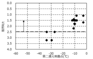
- FIG. 1-1 is a graph showing the relationship between the dew point at the center of the soaking zone and R/t during the second reduction treatment.
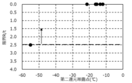
- FIG. 1-2 is another graph showing the relationship between the dew point at the center of the soaking zone and R/t during the second reduction treatment.
- FIG. 2-1 is a graph showing the relationship between the dew point at the center of the soaking zone and the tensile strength TS during the second reduction treatment.
- FIG. 2-2 is another graph showing the relationship between the dew point at the center of the soaking zone and the tensile strength TS during the second reduction treatment.
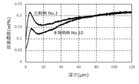
- FIG. 3 is a diagram showing an example of a carbon concentration profile obtained in an example.
- FIG. 1-1 is a graph showing the relationship between the dew point at the center of the soaking zone and R/t during the second reduction treatment.
- FIG. 1-2 is another graph showing the relationship between the dew point at the center of the soaking zone and R/t during the second reduction treatment.
- FIG. 2-1 is a graph
- FIG. 4-1 is a graph showing the relationship between the position where the carbon concentration (mass %) in the sheet thickness direction is 50% of the bulk carbon concentration and R/t.
- FIG. 4-2 is another graph showing the relationship between the position where the carbon concentration (mass %) in the sheet thickness direction is 50% of the bulk carbon concentration and R/t.
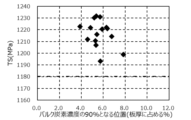
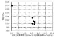
- FIG. 5-1 is a graph showing the relationship between the position in the sheet thickness direction where the carbon concentration (mass %) is 90% of the bulk carbon concentration and the tensile strength TS.
- FIG. 5-2 is another graph showing the relationship between the position in the sheet thickness direction where the carbon concentration (mass %) is 90% of the bulk carbon concentration and the tensile strength TS.
- FIG. 6-1 is a graph showing the relationship between the ratio of the maximum carbon concentration (mass %) in the region from the steel sheet surface to 20 ⁇ m deep to the bulk carbon concentration, and R/t.
- FIG. 6-2 is another graph showing the relationship between the ratio of the maximum carbon concentration (mass %) in the region from the steel sheet surface to 20 ⁇ m deep to the bulk carbon concentration, and R/t.
- FIG. 7-1 is a graph showing the relationship between the amount of surface decarburization per 1 mm of plate thickness and the tensile strength TS.
- FIG. 7-2 is another graph showing the relationship between the amount of surface decarburization per mm of plate thickness and the tensile strength TS.
- the inventors conducted extensive research to obtain a steel sheet that exhibits excellent bendability in bending even when it is high in strength. As a result, they discovered that by providing a decarburized layer within a specified range on the surface layer of the steel sheet, it is possible to obtain excellent bendability while maintaining high strength. They also discovered that in order to form a decarburized layer within a specified range on the surface layer of the steel sheet that can achieve both high strength and excellent bendability, it is sufficient to control the conditions when annealing the steel sheet (original sheet). Below, the steel sheet of this embodiment will first be described.
- the steel plate according to this embodiment is (I) In the plate thickness direction, The position where the carbon concentration (mass %) is 50% of the bulk carbon concentration is in a region that is 0.20% or more of the plate thickness from the steel plate surface, and the position where the carbon concentration (mass %) is 90% of the bulk carbon concentration is in a region that is 8.0% or less of the plate thickness from the steel plate surface.
- the position where the carbon concentration (mass %) is 50% of the bulk carbon concentration in the plate thickness direction is in an area 0.20% or more of the plate thickness from the surface of the steel plate.
- the position relates to the thickness of the decarburized layer that contributes to bendability. By ensuring that the position is in an area 0.20% or more of the plate thickness from the surface of the steel plate and that the decarburized layer is of a certain thickness or more that contributes to bendability, it is possible to reliably achieve excellent bendability in bending.
- the position where the carbon concentration (mass %) is 50% of the bulk carbon concentration may be in an area 0.5% or more, or even 1.0% or more of the plate thickness from the surface of the steel plate.
- the position where the carbon concentration (mass %) is 90% of the bulk carbon concentration in the plate thickness direction is in a region of 8.0% or less of the plate thickness from the surface of the steel plate.
- Increasing the thickness of the decarburized layer improves bendability, but the strength is likely to decrease.
- the inventors have found through their investigation that if the position where the carbon concentration (mass %) is 90% of the bulk carbon concentration is in a region of 8.0% or less of the plate thickness from the surface of the steel plate, the decrease in strength can be sufficiently suppressed.
- the position where the carbon concentration (mass %) is 90% of the bulk carbon concentration may be 6.0% or less of the plate thickness from the surface of the steel plate.
- the steel plate according to this embodiment is (II)
- the maximum carbon concentration (mass%) in a region from the steel sheet surface to 20 ⁇ m in the sheet thickness direction is less than 70% of the bulk carbon concentration, and the amount of surface decarburization per mm of sheet thickness on one side of the steel sheet is 0.045 mol/ m2 or less, preferably 0.035 mol/m2 or less .
- the inventors examined conventional steel plates they first found that there were areas in the surface layer of the steel plate with extremely high carbon concentrations, which were the cause of the deterioration of bendability. They then investigated the manufacturing conditions of the steel plate, as described below, and found that excellent bendability can be easily obtained by promoting decarburization of the surface layer of the steel plate and suppressing the carbon concentration in the surface layer of the steel plate; more specifically, by suppressing the maximum carbon concentration (mass%) in the region from the surface of the steel plate to 20 ⁇ m in the plate thickness direction to less than 70% of the bulk carbon concentration.
- the maximum carbon concentration is preferably 65% or less of the bulk carbon concentration, and more preferably 60% or less of the bulk carbon concentration.
- the steel plate according to this embodiment has a surface decarburization amount per mm of plate thickness on one side of the steel plate of 0.045 mol/ m2 or less, preferably 0.035 mol/m2 or less , thereby ensuring a high tensile strength of 980 MPa or more, particularly 1180 MPa or more.
- the surface decarburization amount per mm of plate thickness is more preferably 0.030 mol/m2 or less , and even more preferably 0.025 mol/m2 or less .
- the steel plate according to this embodiment only needs to satisfy at least one of (I) and (II) above in order to achieve both high strength and excellent bendability, and preferably satisfies (I) above, and more preferably satisfies both (I) and (II) above.
- the "steel sheet surface” refers to the surface of the steel sheet in the case of a steel sheet obtained by annealing a cold-rolled steel sheet, and to the position of the interface between the plating layer and the base steel sheet in the case of a plated steel sheet.
- the position of the interface between the plating layer and the base steel sheet refers to the point where Zn constituting the plating layer is no longer detectable (the Zn analysis value is 0) when Zn is analyzed from the surface of the plating layer in the thickness direction of the plating layer in the case of zinc-based plating, for example, using GD-OES as described in the examples below, and this point is regarded as the starting point of the distance (depth) from the steel sheet surface.
- the steel plate according to this embodiment has high strength but exhibits excellent bendability in bending processing.
- the strength can be, for example, a tensile strength TS of 980 MPa or more, preferably 1180 MPa or more.
- the steel plate according to this embodiment exhibits excellent bendability with a limit R/t of less than 2.5 when subjected to a bending test shown in the examples described later.
- the thickness of the steel sheet according to this embodiment is not limited.
- the thickness of the steel sheet according to this embodiment (the thickness of the base steel sheet in the case of a plated steel sheet) can be, for example, 0.4 mm or more and 4 mm or less.
- the steel sheet according to the present embodiment may have a Si content of more than 0.5 mass% in the composition.
- the Si content is more preferably 1.0 mass% or more, even more preferably 1.1 mass% or more, and even more preferably 1.2 mass% or more.
- the upper limit of the Si content may be, for example, 3.0 mass%.
- the composition of the steel sheet is C: 0.08% by mass or more, 0.30% by mass or less, Si: more than 0.5 mass%, 3.0 mass% or less, Mn: 1.5% by mass or more, 3.0% by mass or less, Cr: 0 mass% or more, 1.0 mass% or less, P: more than 0 mass%, 0.1 mass% or less, S: more than 0% by mass, 0.05% by mass or less, Al: more than 0 mass% and 1.0 mass% or less; and N: more than 0 mass% and 0.01 mass% or less;
- the balance is Fe and unavoidable impurities. Each element will be described below.
- C is an element effective in improving the strength of steel plate, and is a particularly effective strengthening element for ensuring the tensile strength of the steel plate of 980 MPa or more, and even 1180 MPa or more, by including Si and, if necessary, Mn in the steel. Furthermore, C is also an element necessary for ensuring the retained austenite and improving the workability. In order to effectively exert such an action, the C content is preferably 0.08 mass% or more, more preferably 0.11 mass% or more, and even more preferably 0.13 mass% or more.
- the C content is preferably 0.30 mass% or less, more preferably 0.25 mass% or less, and even more preferably 0.23 mass% or less.
- Mn preferably 1.5% by mass or more and 3.0% by mass or less
- Mn is an inexpensive strengthening element for steel and is effective in improving the strength of steel plate.
- Mn is a particularly effective strengthening element for ensuring the final tensile strength of the steel plate of 980 MPa or more, and even 1180 MPa or more, by being contained in the steel together with Si and, if necessary, together with C.
- Mn is also an element that stabilizes austenite and contributes to improving the workability of the steel plate by the generation of retained austenite.
- the Mn content is preferably 1.5 mass% or more, more preferably 1.8 mass% or more, and even more preferably 2.0 mass% or more.
- the Mn content is preferably 3.0 mass% or less, more preferably 2.8 mass% or less, and even more preferably 2.7 mass% or less.
- Silicon is an inexpensive steel strengthening element that does not easily affect the workability of steel sheets. Silicon also prevents the decomposition of retained austenite, which is useful for improving the workability of steel sheets, to form carbides.
- the Si content is more than 0.5 mass%, preferably 1.0 mass% or more, more preferably 1.1 mass% or more, and further The upper limit of the Si content is preferably 1.2 mass % or more. Although there is no particular upper limit for the Si content, if the Si content is too high, the solid solution strengthening effect of Si becomes significant, and there is a risk of increasing the rolling load.
- the Si content is preferably 3.0 mass % or less. % or less, more preferably 2.7% or less by mass, and further preferably 2.5% or less by mass.
- Cr is an element effective in improving the strength of the steel sheet. Furthermore, Cr is an element that improves the corrosion resistance of the steel sheet, and has the effect of suppressing the generation of hydrogen due to corrosion of the steel sheet. Specifically, Cr has the effect of promoting the generation of iron oxide ( ⁇ -FeOOH). Iron oxide is said to be thermodynamically stable and protective among rusts that are generated in the atmosphere. By promoting the generation of such rust, it is possible to suppress the intrusion of the generated hydrogen into the steel sheet, and even when the steel sheet is used in a severe corrosive environment, for example, in the presence of chlorides, hydrogen-assisted cracking can be sufficiently suppressed.
- Cr is an element that is also effective in the delayed fracture resistance of the steel sheet, so that it can be contained in an amount that does not affect the strength and workability such as elongation of the steel sheet.
- the Cr content may be 0% by mass, but in order to effectively exert these effects, the Cr content is preferably more than 0% by mass, more preferably 0.003% by mass or more, and even more preferably 0.01% by mass or more.
- the Cr content is preferably 1.0 mass% or less, more preferably 0.8 mass% or less, and further preferably 0.6 mass% or less.
- P preferably more than 0 mass% and 0.1 mass% or less
- P is an element that is inevitably present as an impurity element. If the P content is excessive, it may deteriorate the weldability. Therefore, the P content is preferably suppressed to 0.1 mass% or less, more preferably 0.08 mass% or less, and further preferably 0.05 mass% or less.
- S is an element that is inevitably present as an impurity element.
- steel inevitably contains about 0.0005 mass% of S. If the S content is excessive, it may form sulfide-based inclusions, promote hydrogen absorption in a corrosive environment, deteriorate the delayed fracture resistance of the steel sheet, and deteriorate the weldability and workability of the steel sheet. Therefore, the S content is preferably suppressed to 0.05 mass% or less, more preferably 0.01 mass% or less, and further preferably 0.005 mass% or less.
- Al is an element having a deoxidizing effect.
- the Al content is preferably more than 0 mass%, more preferably 0.005 mass% or more, and even more preferably 0.02 mass% or more. If the Al content is excessive, inclusions such as alumina may increase, and the workability of the steel sheet may deteriorate. Therefore, the Al content is preferably 1.0 mass% or less, more preferably 0.8 mass% or less, and even more preferably 0.5 mass% or less.
- N is an element that is inevitably present as an impurity element. If the N content is excessive, nitrides may be formed, which may deteriorate the workability of the steel sheet. In particular, when the steel sheet contains B to improve the hardenability, N combines with B to form BN precipitates, which inhibits the hardenability improving effect of B. Therefore, the N content is preferably suppressed to 0.01 mass% or less, more preferably 0.008 mass% or less, and even more preferably 0.005 mass% or less.
- the balance is Fe and inevitable impurities.
- inevitable impurities the inclusion of trace elements (e.g., As, Sb, Sn, etc.) brought in due to the conditions of raw materials, materials, manufacturing equipment, etc. is permitted.
- P, S, and N are usually preferable as the content is small, so they can also be called inevitable impurities.
- the present disclosure is defined as above because the effect can be easily achieved by suppressing the content of these elements to a specific range.
- the "unavoidable impurities" constituting the balance are a concept excluding elements whose composition ranges are specified.
- Optional components include Cu, Ni, Ti, Nb, V, and B. These optional components are described below.
- Cu is an element that is effective in improving the strength of the steel sheet and has the effect of suppressing hydrogen generation due to corrosion of the steel sheet, thereby improving the corrosion resistance of the steel sheet.
- Cu has the effect of promoting the formation of iron oxide.
- the Cu content is preferably more than 0 mass%, more preferably 0.003 mass% or more, and even more preferably 0.05 mass% or more.
- the Cu content is preferably 1.0 mass% or less, more preferably 0.8 mass% or less, and even more preferably 0.5 mass% or less.
- Ni, like Cr and Cu is an element that is effective in improving the strength of the steel sheet and has the effect of suppressing hydrogen generation due to corrosion of the steel sheet, thereby improving the corrosion resistance of the steel sheet.
- Ni, like Cr and Cu has the effect of promoting the formation of iron oxide.
- the Ni content is preferably more than 0 mass%, more preferably 0.003 mass% or more, and even more preferably 0.05 mass% or more.
- the Ni content is preferably 1.0 mass% or less, more preferably 0.8 mass% or less, and even more preferably 0.5 mass% or less.
- Ti is an element that is effective in improving the strength of a steel sheet and has the effect of suppressing hydrogen generation due to corrosion of the steel sheet, thereby improving the corrosion resistance of the steel sheet.
- Ti, like Cr, Cu, and Ni has the effect of promoting the formation of iron oxide.
- Ti, like B and Cr is also an element that is effective in improving the delayed fracture resistance of the steel sheet, so it can be contained in an amount that does not affect the strength and workability such as elongation of the steel sheet.
- the Ti content is preferably more than 0 mass%, more preferably 0.003 mass% or more, and even more preferably 0.05 mass% or more.
- the Ti content is preferably 0.15 mass% or less, more preferably 0.12 mass% or less, and even more preferably 0.10 mass% or less.
- Nb is an element that is effective in improving the strength of steel plate and also acts to refine austenite grains after quenching, thereby improving the toughness of the steel plate.
- the Nb content is preferably more than 0 mass%, more preferably 0.003 mass% or more, and even more preferably 0.005 mass% or more.
- the Nb content is preferably 0.15 mass% or less, more preferably 0.12 mass% or less, and even more preferably 0.10 mass% or less.
- V preferably more than 0 mass% and 0.15 mass% or less
- V is also an element that is effective in improving the strength of steel plate and refines austenite grains after quenching to improve the toughness of the steel plate.
- the V content is preferably more than 0 mass%, more preferably 0.003 mass% or more, and even more preferably 0.005 mass% or more.
- the V content is preferably 0.15 mass% or less, more preferably 0.12 mass% or less, and even more preferably 0.10 mass% or less.
- B is an element useful for improving the hardenability and weldability of steel sheets.
- B is also an element effective for the delayed fracture resistance of steel sheets, so it can be contained in an amount that does not affect the strength and workability such as elongation of the steel sheets.
- the B content is preferably more than 0 mass%, more preferably 0.0002 mass% or more, even more preferably 0.0003 mass% or more, and particularly preferably 0.0004 mass% or more.
- the B content is preferably 0.005 mass% or less, more preferably 0.004 mass% or less, and even more preferably 0.003 mass% or less.
- the steel sheet may be a cold-rolled steel sheet, a plated steel sheet, or the like.
- the type of plated steel sheet is not limited, and may be, for example, a zinc-based plated steel sheet that is plated with a zinc-based coating such as Al-Zn plating, Ni-Zn plating, Fe-Zn plating, Cr-Zn plating, or Mg-Zn plating.
- Specific examples of the zinc-based plated steel sheet include hot-dip galvanized steel sheet (GI), alloyed hot-dip galvanized steel sheet (GA), and electrolytic galvanized steel sheet (EG).
- the method for manufacturing a steel sheet according to this embodiment is as follows:
- the annealing process includes an oxidizing process under conditions of an oxygen concentration of 0.1 to 2% and an ultimate temperature of 650 to 750°C, followed by a reducing process.
- the reduction treatment includes a first reduction treatment in which the dew point is ⁇ 35 to ⁇ 15° C., and then a second reduction treatment in which the dew point is ⁇ 25 to 0° C., which is higher than the dew point of the first reduction treatment.
- an Fe oxide layer is formed on the surface of the steel sheet.
- a reduction treatment is carried out in a reducing atmosphere to form a decarburized layer on the surface of the steel sheet while forming a reduced Fe layer that can, for example, form a good plating layer.
- water vapor is added throughout the reduction treatment, the amount of decarburization may become excessive, resulting in a risk of a decrease in strength.
- decarburization occurs once, but carbon re-diffuses (recarbonizes) in the decarburized area in the second half of the reduction treatment, and bendability does not improve.
- the oxidation treatment is carried out under conditions of an oxygen concentration of 0.1 to 2%.
- the oxygen concentration can be carried out under conditions of 0.0%, in order to obtain a plated steel sheet, it is preferable to set the oxygen concentration to 0.1% or more from the viewpoint of obtaining an excellent plating appearance.
- the oxygen concentration is more preferably 0.15% or more, and even more preferably 0.20% or more.
- the oxygen concentration is set to 2% or less.
- the oxygen concentration is preferably 1.7% or less, and more preferably 1.5% or less.
- concentrations of elements other than oxygen are not particularly limited, and examples thereof include a gas atmosphere containing CO 2 , N 2 , H 2 O, and other inevitable impurities in addition to the oxygen of the above concentration.
- the oxidation treatment can be performed in a DFF (Direct Fired Furnace) type annealing furnace or the like in a combustion gas such as coke oven gas (COG) or liquefied petroleum gas (LPG) in a gas atmosphere in which the concentration of unburned O 2 is controlled.
- COG coke oven gas
- LPG liquefied petroleum gas
- the oxidation treatment is carried out under the condition of an ultimate temperature of 650 to 750°C.
- heating to an ultimate temperature of 650 to 750°C can be performed in an oxidation heating zone in a DFF type annealing furnace.
- the ultimate temperature By setting the ultimate temperature to 750°C or less, it is possible to suppress the reaction between SiO2 on the surface of the steel sheet near the width direction edge and FeO generated by the oxidation treatment.
- the steel sheet according to this embodiment is a plated steel sheet, good plating adhesion can be obtained.
- the "achieved temperature" during heating in the oxidation treatment refers to the maximum temperature reached by the steel plate as the heating is controlled in the oxidation heating zone.
- the temperature reached in the oxidation treatment is preferably 730°C or lower, more preferably 720°C or lower, and even more preferably 700°C or lower.
- the steel sheet temperature in the oxidation treatment is 650°C or higher from the viewpoint of forming an Fe oxide layer in the above gas atmosphere.
- the steel sheet temperature in the oxidation treatment is preferably 670°C or higher.
- the temperature rise time in the oxidation treatment is not particularly limited, and may be adjusted so that an excessively long time does not result in the formation of a fayalite layer that adversely affects plating properties, for example.
- the temperature rise time in the oxidation treatment may be appropriately adjusted in consideration of the hot rolling conditions (particularly the coiling temperature), the annealing conditions before pickling, the pickling conditions, and the steel sheet temperature during heating in the oxidation treatment.
- the temperature rise time in the oxidation treatment is preferably 10 seconds or more, more preferably 15 seconds or more.
- the temperature rise time in the oxidation treatment is preferably 120 seconds or less, more preferably 90 seconds or less. Note that, although the above describes a case in which the oxidation treatment is performed while increasing the temperature, the mode of the oxidation treatment is not limited to this, and the oxidation treatment may be performed by increasing the temperature to the target temperature and holding the target temperature, etc.
- the reduction treatment In the reduction treatment, a desired decarburized layer is formed on the surface layer of the steel sheet. In addition, in the case where the steel sheet is a plated steel sheet, for example, a reduced Fe layer capable of forming a good plated layer is formed.
- the reduction treatment is performed by first reducing treatment having a dew point of -35 to -15°C, followed by second reducing treatment having a dew point of -25 to 0°C, which is higher than that of the first reducing treatment.
- first reducing treatment and the second reducing treatment will be described respectively.
- First reduction treatment In the first reduction treatment, the dew point is set in the range of -35 to -15°C.
- the dew point is set to -15°C or lower.
- the dew point is preferably -20°C or lower.
- the dew point in the first reduction treatment is set to -35°C or higher.
- the dew point is preferably -30°C or higher.
- the dew point in the atmosphere at the center of the front stage of the reduction zone where the first reduction process is performed is within the above range.
- the dew point in the first reduction process and the second reduction process described below can be controlled, for example, by introducing water vapor gas and mixing it with the atmospheric gas in the furnace, or by bubbling the atmospheric gas and mixing it with water vapor.
- the atmosphere of the first reduction treatment may be an atmosphere that satisfies the above dew point and contains N 2 , H 2 , CO, H 2 O, O 2 , and other inevitable impurities.
- the temperature may be held in the temperature range of 800 to 920° C. for, for example, 60 to 240 seconds.
- the "holding" may be at a constant temperature, or may be fluctuating within the temperature range.
- FIG. 1-1 No. 1 to 16
- FIG. 1-2 No. 17 to 22
- FIG. 1-1 and FIG. 1-2 are graphs created using the examples described later, and are graphs showing the relationship between the dew point at the center of the soaking zone during the second reduction treatment and R/t. From these FIG. 1-1 and FIG. 1-2, it can be seen that in order to achieve excellent bendability with R/t of less than 2.5 as shown by the arrows in the drawings, it is necessary to set the dew point in the second reduction treatment to -25°C or higher. Also, FIG. 2-1 (No. 1 to 16) and FIG. 2-2 (No.
- FIG. 17 to 22 are graphs created using the examples described later, and are graphs showing the relationship between the dew point at the center of the soaking zone during the second reduction treatment and tensile strength TS. From these FIG. 2-1 and FIG. 2-2, it can be seen that by setting the dew point to 0°C or lower, a high strength of tensile strength TS of 980 MPa or higher, or even 1180 MPa or higher can be ensured.
- the dew point in the second reduction treatment is preferably -15°C or lower.
- the atmosphere of the second reduction treatment may be an atmosphere that satisfies the above dew point and contains N 2 , H 2 , CO, H 2 O, O 2 , and other unavoidable impurities.
- the steel sheet may be held in the above atmosphere for, for example, 60 to 240 seconds in a temperature range in which the steel sheet reaches a temperature of 800 to 920° C.
- the "holding" may be at a constant temperature, or may be held at a temperature that varies within the above temperature range.
- the first reduction process and the second reduction process may be performed in separate atmospheres with different dew points as described above, and the specific form is not limited.
- a reduction furnace may be provided for performing the first reduction process and the second reduction process, and in the case where the steel sheet is a plated steel sheet, a partition wall with an opening area ratio of 20% or less may be provided midway through the reduction zone of the continuous hot-dip plating line to separate the front-stage region for performing the first reduction process from the rear-stage region for performing the second reduction process.
- first and second reduction treatments it is permissible to insert a process such as a holding process for maintaining at least one of the conditions (dew point, heating temperature) of the first reduction treatment, or a cooling process for cooling to a temperature between the heating temperature of the first reduction treatment and room temperature, as long as this process does not adversely affect the decarburization of the steel plate according to this embodiment. It is preferable to carry out the second reduction treatment following the first reduction treatment.
- the oxidation and reduction treatments may be carried out using any known single or multiple pieces of equipment.
- a continuous hot-dip galvanizing line CGL
- the oxidation and reduction treatments by the oxidation-reduction method, and the hot-dip galvanizing and alloying treatments when manufacturing, for example, a galvanized steel sheet as a steel sheet can be carried out continuously in a series of production lines.
- the oxidation and reduction treatments by the oxidation-reduction method can be carried out, for example, using an annealing furnace in a DFF-type continuous hot-dip galvanizing line.
- the oxidation treatment can be carried out, for example, in the heating zone in a DFF-type annealing furnace as described above.
- the reduction treatment can be carried out, for example, in the soaking zone in a DFF-type annealing furnace.
- the manufacturing method of the steel plate (original plate) to be annealed is not particularly limited.
- the steel plate (original plate) to be annealed can be obtained by melting and casting steel in a conventional manner to obtain a steel slab, and then subjecting the steel slab to a rolling process (hot rolling, cold rolling) in a conventional manner.
- the manufacturing method according to this embodiment is not limited as long as it includes the annealing step.
- the steel sheet according to this embodiment may be a cold-rolled steel sheet that has been annealed without undergoing any of the steps after the annealing step.
- a plating step such as a hot-dip galvanizing step or even an alloying step may be provided after annealing, to obtain, for example, a hot-dip galvanized steel sheet (GI) or an alloyed hot-dip galvanized steel sheet (GA) as the steel sheet according to this embodiment.
- an electrogalvanizing step may be provided to obtain, for example, an electrogalvanized steel sheet (EG) as the steel sheet according to this embodiment.
- the method for forming a zinc plating layer on the surface of the steel sheet after the annealing is not particularly limited, and a known method can be appropriately used.
- the base material after the annealing step can be immersed in a plating bath.
- the plating bath can be, for example, a binary or higher alloy plating containing Zn.
- binary or higher alloy plating containing Zn include Al-Zn plating, Fe-Zn plating, Ni-Zn plating, Cr-Zn plating, Mg-Zn plating, etc.
- the plating may be performed by using a plating bath containing components other than zinc at a concentration of, for example, 0.01% by mass to 0.5% by mass, and impregnating the material at a temperature of, for example, 300°C to 600°C for, for example, 1 second to 30 seconds.
- the alloying treatment is also not particularly limited, and any known method may be used as appropriate. For example, reheating may be performed at an alloying temperature of 470°C to 600°C for 1 second to 100 seconds.
- the composition of the steel plate (original plate) was bulk carbon concentration, i.e., the C content of the steel plate (original plate) was 0.22 mass%, the Si content was 1.7 mass%, the Mn content was 2.0 mass%, the Cr content was 0.5 mass%, the Al content was 0.04 mass%, and the balance was Fe and unavoidable impurities (note that "unavoidable impurities” here includes P, S, and N in amounts within the ranges mentioned above), and the original plate had a structure of ferrite + pearlite and a strength of 700 to 800 MPa.
- unavoidable impurities here includes P, S, and N in amounts within the ranges mentioned above
- base plates were prepared having a bulk carbon concentration of 0.13 mass% (0.13 mass% C), a Si content of 0.9 mass%, a Mn content of 2.3 mass%, a Cr content of 0.57 mass%, an Al content of 0.02 mass%, and the balance being Fe and inevitable impurities (note that "unavoidable impurities” here includes P, S, and N in amounts within the ranges mentioned above), a structure of ferrite + pearlite, and a strength of 700 to 800 MPa.
- unavoidable impurities here includes P, S, and N in amounts within the ranges mentioned above
- the bulk carbon concentration was 0.21% by mass (0.21% by mass C)
- the Si content was 1.8% by mass
- the Mn content was 2.3% by mass
- the Al content was 0.45% by mass
- the balance was Fe and inevitable impurities (note that "unavoidable impurities” here includes P, S, and N in amounts within the ranges mentioned above)
- the structure was ferrite + pearlite, and the base plate had a strength of 600 to 700 MPa.
- the annealing samples were subjected to oxidation and reduction treatments using an actual machine.
- oxidation treatment was performed at the oxygen concentration and ultimate temperature shown in Table 1, and then the first reduction treatment (heating zone) and second reduction treatment (soaking zone) shown in Table 1 were performed in this order under each of the conditions (ultimate temperature, dew point) shown in Table 1.
- the conditions for the "first reduction zone” in Table 1 indicate the conditions for the first reduction treatment, and the conditions for the "second reduction zone” indicate the conditions for the second reduction treatment.
- the steel sheet after the second reduction treatment was cooled to 460°C, and then dipped in an Al-Zn plating bath containing 0.08 to 0.13 mass% Al (Al is effective Al%, plating bath temperature is 460 to 480°C) to perform galvanization.
- the coating weight was controlled to 40 g/m2 or more and 90 g/ m2 or less by gas wiping, and then alloying treatment was performed at 480 to 490°C for 20 to 30 seconds to obtain a galvannealed steel sheet.
- the obtained galvannealed steel sheets were evaluated as follows:
- Sample Preparation Materials measuring 50 mm x 40 mm x thickness or 30 mm x 30 mm x thickness were collected. After that, samples were prepared by degreasing in the usual manner. Then, using the samples, the mass% concentration of each element was measured by GD-OES under the following conditions.
- GD-OES measurements were performed on the plated surface of the sample up to a depth of 150 ⁇ m in the plate thickness direction.
- the details of the calibration curve method for converting the measured emission intensity of each element into a concentration are shown below.
- the relationship between the sputter weight W i (g/sec) of element i per unit time and the emission intensity I i is expressed by the following formula (1) using the slope a and intercept b of the calibration curve.
- W i aI i +b...Formula (1)
- the sputter weight W i of the above element i per unit time can be calculated using the sputter area S (cm 2 ) of a reference sample whose concentration C i (wt. %), density ⁇ (g/cm 3 ), and sputter rate ⁇ d (cm/ sec ) are known, according to the following formula (2).
- W i C i ⁇ d ⁇ S...Formula (2)
- Emission intensity Ii was measured using two or more reference samples with known Wi , and the slope a and intercept b of the above formula (1) were determined to create a calibration curve with emission intensity on the horizontal axis and sputter weight on the vertical axis.
- the reference samples used are shown in Table 2 below.
- the sputter weight was determined from the emission intensity of each target element, and the concentration was converted from the weight ratio.
- the calibration curve used to convert the O concentration was corrected using SiO2 so that the concentration ratio of Si to O was 1:2.
- FIG. 3 shows No. 2, a comparative example, and No. 10, an example of the present invention.
- the carbon profile of each material has a carbon concentration peak within 20 ⁇ m of the surface layer (specifically, in the internal oxidation layer), but while the carbon concentration is higher than the bulk carbon concentration in the comparative example, it is sufficiently lower than the bulk carbon concentration in the example of the present invention.
- the bulk carbon concentration of the sample used in this example is 0.22 mass%
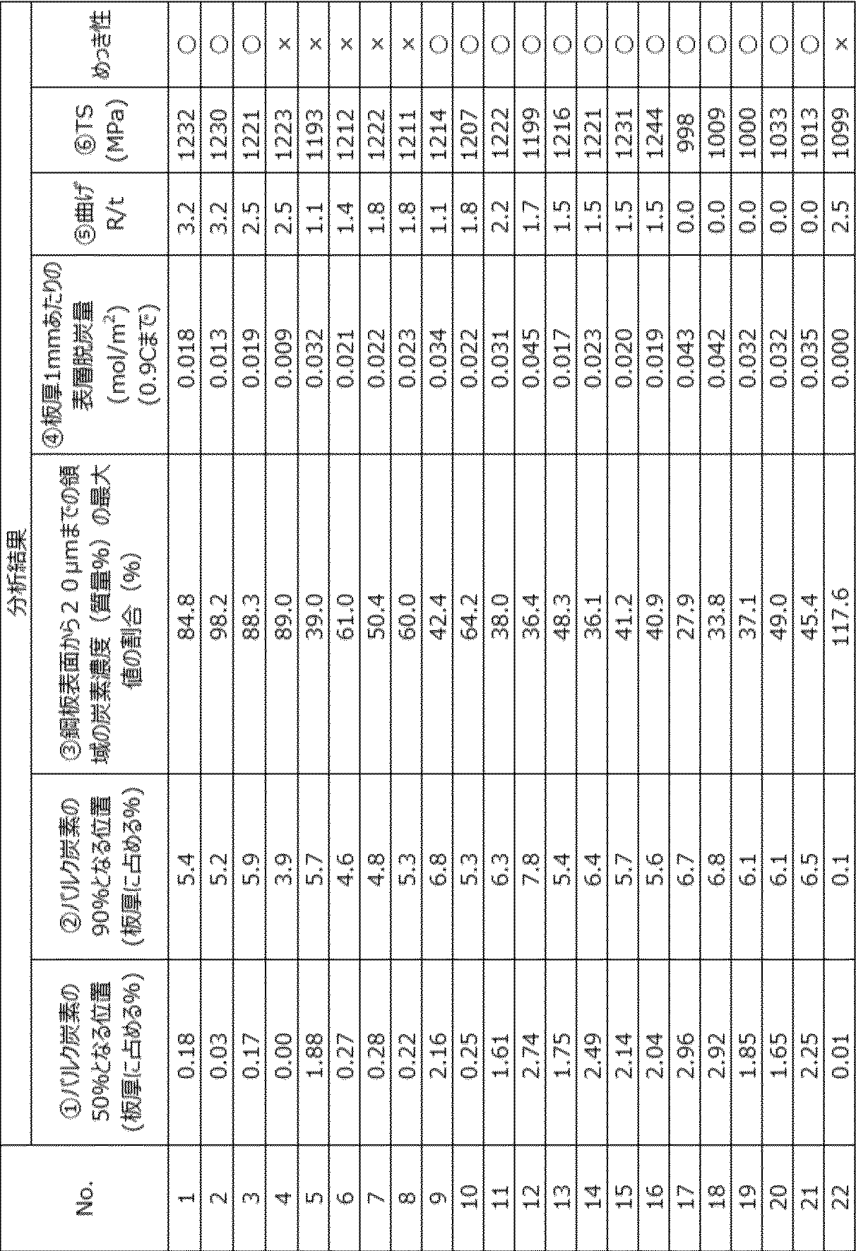
- the position where the carbon concentration (mass%) is 50% of the bulk carbon concentration, the position where the carbon concentration (mass%) is 90% of the bulk carbon concentration, and the maximum carbon concentration (mass%) in the region up to 20 ⁇ m from the steel plate surface were determined.
- the bulk carbon concentration was corrected for use in the analysis so that the carbon concentration at a sufficiently deep position (120-150 ⁇ m) measured by GD-OES was the value obtained by normal steel analysis. For example, if the steel analysis value was 0.22% and the GD-OES analysis value was 0.25%, the GD-OES analysis value was multiplied by 0.22/0.25 and used in the analysis.
- the amount of surface decarburization per mm of sheet thickness on one side of the steel sheet was calculated as follows.
- the amount of desorbed carbon was first calculated from the difference between the bulk carbon concentration and the carbon concentration profile of the steel sheet (after decarburization). That is, for 1 m2 of steel sheet, the total amount of decarburization was calculated by: iron volume in the decarburized portion ( m3 ) x iron density (specific gravity) (7.87 x 10⁶ g/ m3 ) x proportion of decarburized carbon in the iron in the decarburized portion / atomic weight of carbon (g/mol). The total amount of decarburization was then divided by the sheet thickness to calculate the amount of surface decarburization per mm of sheet thickness on one side of the steel sheet (mol/ m2 ).
- TS tensile strength
- Nos. 1 to 4 and 22 did not have the surface layer of the steel plate defined in this embodiment and had poor bendability.
- Aspect 1 of the present invention is In the plate thickness direction, This steel plate has a position where the carbon concentration (mass %) is 50% of the bulk carbon concentration in a region that is 0.20% or more of the plate thickness from the steel plate surface, and a position where the carbon concentration (mass %) is 90% of the bulk carbon concentration in a region that is 8.0% or less of the plate thickness from the steel plate surface.
- Aspect 2 of the present invention is The steel sheet according to aspect 1, wherein the maximum carbon concentration (mass%) in a region from the steel sheet surface to 20 ⁇ m in the sheet thickness direction is less than 70% of the bulk carbon concentration, and the amount of surface decarburization per mm of sheet thickness on one side of the steel sheet is 0.035 mol/m2 or less.
- Aspect 3 of the present invention is 3. The steel plate according to claim 1 or 2, having a tensile strength of 1180 MPa or more.
- Aspect 4 of the present invention is The composition of the components is C: 0.08% by mass or more, 0.30% by mass or less, Si: more than 0.5 mass%, 3.0 mass% or less, Mn: 1.5% by mass or more, 3.0% by mass or less, Cr: more than 0 mass%, 1.0 mass% or less, P: more than 0 mass%, 0.1 mass% or less, S: more than 0 mass%, 0.05 mass% or less, Al: more than 0 mass% and 1.0 mass% or less; and N: more than 0 mass% and 0.01 mass% or less;
- the steel sheet according to any one of Aspects 1 to 3, wherein the balance is Fe and unavoidable impurities.
- Aspect 5 of the present invention is The annealing process includes an oxidizing process under conditions of an oxygen concentration of 0.1 to 2% and an ultimate temperature of 650 to 750°C, followed by a reducing process.
- the reduction treatment is a method for producing a steel sheet, which includes a first reduction treatment having a dew point of -35 to -15°C, followed by a second reduction treatment having a dew point of -25 to 0°C, which is higher than that of the first reduction treatment.
- Aspect 6 of the present invention is A method for producing a steel sheet according to aspect 5, wherein an ultimate temperature in the first reduction treatment and the second reduction treatment is 800 to 920°C.
Landscapes
- Chemical & Material Sciences (AREA)
- Engineering & Computer Science (AREA)
- Materials Engineering (AREA)
- Mechanical Engineering (AREA)
- Metallurgy (AREA)
- Organic Chemistry (AREA)
- Physics & Mathematics (AREA)
- Thermal Sciences (AREA)
- Crystallography & Structural Chemistry (AREA)
- Chemical Kinetics & Catalysis (AREA)
- Oil, Petroleum & Natural Gas (AREA)
- Heat Treatment Of Sheet Steel (AREA)
Abstract
Description
板厚方向において、
炭素濃度(質量%)がバルク炭素濃度の50%である位置は、鋼板表面から板厚の0.20%以上の領域にあり、かつ
炭素濃度(質量%)がバルク炭素濃度の90%である位置は、鋼板表面から板厚の8.0%以下の領域にある、鋼板である。
板厚方向における鋼板表面から20μmまでの領域の炭素濃度(質量%)の最大値は、バルク炭素濃度の70%未満であり、かつ
鋼板の片面における板厚1mmあたりの表層脱炭量は、0.045mol/m2以下である、態様1に記載の鋼板である。
引張強さが980MPa以上である、態様1または2に記載の鋼板である。
成分組成が、
C :0.08質量%以上、0.30質量%以下、
Si:0.5質量%超、3.0質量%以下、
Mn:1.5質量%以上、3.0質量%以下、
Cr:0質量%以上、1.0質量%以下、
P :0質量%超、0.1質量%以下、
S :0質量%超、0.05質量%以下、
Al:0質量%超、1.0質量%以下、および
N :0質量%超、0.01質量%以下を満たし、
残部がFeおよび不可避不純物である、態様1~3のいずれか1つに記載の鋼板である。
酸素濃度0.1~2%、到達温度650~750℃の条件で酸化処理した後、還元処理を行う焼鈍工程を含み、
前記還元処理は、露点が-35~-15℃である第1還元処理を経た後、露点が-25~0℃であって第1還元処理よりも露点の高い第2還元処理を経ることを含む、鋼板の製造方法である。
前記第1還元処理と前記第2還元処理における到達温度は800~920℃である、態様5に記載の鋼板の製造方法である。
(鋼板表層の脱炭層)
本実施形態に係る鋼板は、
(I)板厚方向において、
炭素濃度(質量%)がバルク炭素濃度の50%である位置は、鋼板表面から板厚の0.20%以上の領域にあり、かつ
炭素濃度(質量%)がバルク炭素濃度の90%である位置は、鋼板表面から板厚の8.0%以下の領域にある。
(II)板厚方向における鋼板表面から20μmまでの領域の炭素濃度(質量%)の最大値が、バルク炭素濃度の70%未満であり、かつ
鋼板の片面における板厚1mmあたりの表層脱炭量が、0.045mol/m2以下、好ましくは0.035mol/m2以下でもある。
高強度を達成するにあたり、本実施形態に係る鋼板は、成分組成において、例えばSi含有量が0.5質量%超でありうる。Si含有量は、より好ましくは1.0質量%以上、更に好ましくは1.1質量%以上、より更に好ましくは1.2質量%以上である。Si含有量の上限は、例えば3.0質量%でありうる。
C :0.08質量%以上、0.30質量%以下、
Si:0.5質量%超、3.0質量%以下、
Mn:1.5質量%以上、3.0質量%以下、
Cr:0質量%以上、1.0質量%以下、
P :0質量%超、0.1質量%以下、
S :0質量%超、0.05質量%以下、
Al:0質量%超、1.0質量%以下、および
N :0質量%超、0.01質量%以下を満たし、
残部がFeおよび不可避不純物であることが挙げられる。以下、各元素について説明する。
Cは、鋼板の強度向上に有効な元素であり、Siと一緒に、さらに必要に応じてMnも一緒に鋼に含まれることによって、最終的に980MPa以上、更には1180MPa以上の鋼板の引張強さを確保するために特に有効な強化元素である。さらに、Cは、残留オーステナイトを確保して加工性を改善するために必要な元素でもある。このような作用を有効に発揮させるため、C含有量は、好ましくは0.08質量%以上、より好ましくは0.11質量%以上、さらに好ましくは0.13質量%以上である。鋼板の強度確保の観点からはC含有量が多い方が好ましいが、C含有量が多すぎると、耐食性、スポット溶接性および加工性が劣化するおそれがある。そのため、C含有量は、好ましくは0.30質量%以下、より好ましくは0.25質量%以下、さらに好ましくは0.23質量%以下である。
Mnも、Siと同様に、安価な鋼の強化元素であり、鋼板の強度向上に有効である。Mnは、Siと一緒に、さらに必要に応じてCも一緒に鋼に含まれることによって、最終的に980MPa以上、更には1180MPa以上の鋼板の引張強さを確保するために特に有効な強化元素である。さらに、Mnは、オーステナイトを安定化し、残留オーステナイトの生成による鋼板の加工性向上に寄与する元素でもある。このような作用を有効に発揮させるため、Mn含有量は、好ましくは1.5質量%以上、より好ましくは1.8質量%以上、さらに好ましくは2.0質量%以上である。しかしながら、Mn含有量が多すぎると、鋼板の延性が低下し、鋼板の加工性に悪影響を及ぼし、更には鋼板の溶接性が低下するおそれがある。これらの観点から、Mn含有量は、好ましくは3.0質量%以下、より好ましくは2.8質量%以下、さらに好ましくは2.7質量%以下である。
Siは、安価な鋼の強化元素であり、かつ、鋼板の加工性に対して影響を与え難い。また、Siは、鋼板の加工性向上に有用な残留オーステナイトが、分解して炭化物が生成することを抑制できる元素である。このような作用を有効に発揮させるため、Si含有量は0.5質量%超、好ましくは1.0質量%以上、より好ましくは1.1質量%以上、さらに好ましくは1.2質量%以上である。Si含有量の上限は、特に限定されないが、Si含有量が多すぎると、Siによる固溶強化作用が顕著になって圧延負荷が増大してしまうおそれがある。また、熱間圧延の際にSiスケールが発生して鋼板の表面欠陥が生じてしまう可能性がある。そのためSi含有量は、例えば製造安定性の観点から、好ましくは3.0質量%以下、より好ましくは2.7質量%以下、さらに好ましくは2.5質量%以下である。
Crは、鋼板の強度向上に有効な元素である。さらに、Crは、鋼板の耐食性を向上させる元素であり、鋼板の腐食による水素の発生を抑制する作用を有する。具体的には、Crは、酸化鉄(α-FeOOH)の生成を促進させる作用を有する。酸化鉄は、大気中で生成する錆のなかでも熱力学的に安定であり、かつ保護性を有するといわれている。このような錆の生成を促進することによって、発生した水素が鋼板へ侵入することを抑制でき、過酷な腐食環境下、例えば、塩化物の存在下で鋼板を使用した場合でも水素による助長割れを十分に抑制できる。また、Crは、BおよびTiと同様に、鋼板の耐遅れ破壊性にも有効な元素であるため、鋼板の強度と伸び等の加工性に影響を与えない量において含有することができる。Cr含有量は0質量%でもよいが、これらの作用を有効に発揮させるには、Cr含有量は、好ましくは0質量%超、より好ましくは0.003質量%以上、さらに好ましくは0.01質量%以上である。一方、Cr含有量が過剰になると、鋼板の伸び等の加工性が劣化するおそれがある。そのため、Cr含有量は、好ましくは1.0質量%以下、より好ましくは0.8質量%以下、さらに好ましくは0.6質量%以下である。
Pは、不純物元素として不可避的に存在する元素である。P含有量が過剰になると、溶接性を劣化させるおそれがある。そのため、P含有量は、好ましくは0.1質量%以下、より好ましくは0.08質量%以下、さらに好ましくは0.05質量%以下に抑制する。
Sは、不純物元素として不可避的に存在する元素である。通常、鋼は、不可避的に0.0005質量%程度においてSを含有している。S含有量が過剰になると、硫化物系介在物を形成し、腐食環境下で水素吸収を促し、鋼板の耐遅れ破壊性を劣化させ、鋼板の溶接性および加工性を劣化させるおそれがある。そのため、S含有量は、好ましくは0.05質量%以下、より好ましくは0.01質量%以下、さらに好ましくは0.005質量%以下に抑制する。
Alは、脱酸作用を有する元素である。このような作用を有効に発揮させるため、Al含有量は、好ましくは0質量%超、より好ましくは0.005質量%以上、さらに好ましくは0.02質量%以上である。Al含有量が過剰になると、アルミナ等の介在物が増加し、鋼板の加工性が劣化するおそれがある。そのため、Al含有量は、好ましくは1.0質量%以下、より好ましくは0.8質量%以下、さらに好ましくは0.5質量%以下である。
Nは、不純物元素として不可避的に存在する元素である。N含有量が過剰になると、窒化物を形成して鋼板の加工性が劣化するおそれがある。特に、焼入れ性の向上のために鋼板がBを含有する場合、NはBと結合してBN析出物を形成し、Bの焼入れ性向上作用を阻害する。そのため、N含有量は、好ましくは0.01質量%以下、より好ましくは0.008質量%以下、さらに好ましくは0.005質量%以下に抑制する。
残部はFeおよび不可避不純物である。不可避不純物としては、原料、資材、製造設備等の状況によって持ち込まれる微量元素(例えば、As、Sb、Sn等)の混入が許容される。なお、前述したようなP、SおよびNは、通常含有量が少ないほど好ましいため、不可避不純物ともいえる。しかし、これらの元素の含有量が特定の範囲まで抑えられることによって本開示はその効果を容易に発揮できるため、上記のように規定している。このため、本明細書において、残部を構成する「不可避不純物」は、その組成範囲が規定されている元素を除いた概念である。
Cuも、Crと同様に、鋼板の強度向上に有効であり、かつ、鋼板の腐食による水素の発生を抑制する作用を有し、鋼板の耐食性を向上させる元素である。Cuも、Crと同様に、酸化鉄の生成を促進させる作用を有する。これらの作用を有効に発揮させるには、Cu含有量は、好ましくは0質量%超、より好ましくは0.003質量%以上、さらに好ましくは0.05質量%以上である。また、鋼板の加工性の観点から、Cu含有量は、好ましくは1.0質量%以下、より好ましくは0.8質量%以下、さらに好ましくは0.5質量%以下である。
Niも、CrおよびCuと同様に、鋼板の強度向上に有効であり、かつ、鋼板の腐食による水素の発生を抑制する作用を有し、鋼板の耐食性を向上させる元素である。Niも、CrおよびCuと同様に、酸化鉄の生成を促進させる作用を有する。これらの作用を有効に発揮させるには、Ni含有量は、好ましくは0質量%超、より好ましくは0.003質量%以上、さらに好ましくは0.05質量%以上である。また、鋼板の加工性確保の観点から、Ni含有量は、好ましくは1.0質量%以下、より好ましくは0.8質量%以下、さらに好ましくは0.5質量%以下である。
Tiも、Cr、CuおよびNiと同様に、鋼板の強度向上に有効であり、かつ、鋼板の腐食による水素の発生を抑制する作用を有し、鋼板の耐食性を向上させる元素である。Tiも、Cr、CuおよびNiと同様に、酸化鉄の生成を促進させる作用を有する。また、Tiは、BおよびCrと同様に、鋼板の耐遅れ破壊性にも有効な元素であるため、鋼板の強度と伸び等の加工性に影響を与えない量において含有させることができる。これらの作用を有効に発揮させるには、Ti含有量は、好ましくは0質量%超、より好ましくは0.003質量%以上、さらに好ましくは0.05質量%以上である。また、鋼板の加工性確保の観点から、Ti含有量は、好ましくは0.15質量%以下、より好ましくは0.12質量%以下、さらに好ましくは0.10質量%以下である。
Nbは、鋼板の強度向上に有効であり、かつ、焼入れ後のオーステナイト粒を微細化して鋼板の靭性の改善に作用する元素である。このような作用を有効に発揮させるには、Nb含有量は、好ましくは0質量%超、より好ましくは0.003質量%以上、さらに好ましくは0.005質量%以上である。一方、Nb含有量が過剰になると、炭化物、窒化物または炭窒化物を多量に生成し、鋼板の加工性または耐遅れ破壊性が劣化するおそれがある。そのため、Nb含有量は、好ましくは0.15質量%以下、より好ましくは0.12質量%以下、さらに好ましくは0.10質量%以下である。
Vも、Nbと同様に、鋼板の強度向上に有効であり、かつ、焼入れ後のオーステナイト粒を微細化して鋼板の靭性の改善に作用する元素である。このような作用を有効に発揮させるには、V含有量は、好ましくは0質量%超、より好ましくは0.003質量%以上、さらに好ましくは0.005質量%以上である。一方、V含有量が過剰になると、Nbと同様に、炭化物、窒化物または炭窒化物を多量に生成し、鋼板の加工性または耐遅れ破壊性が劣化するおそれがある。そのため、V含有量は、好ましくは0.15質量%以下、より好ましくは0.12質量%以下、さらに好ましくは0.10質量%以下である。
Bは、鋼板の焼入れ性および溶接性の向上に有用な元素である。また、Bは、TiおよびCrと同様に、鋼板の耐遅れ破壊性にも有効な元素であるため、鋼板の強度と伸び等の加工性に影響を与えない量において含有させることができる。これらの作用を有効に発揮させるには、B含有量は、好ましくは0質量%超、より好ましくは0.0002質量%以上、さらに好ましくは0.0003質量%以上、特に好ましくは0.0004質量%以上である。一方、B含有量が過剰になると、このような効果は飽和し、かつ、延性が低下して加工性が悪くなるおそれがある。そのため、B含有量は、好ましくは0.005質量%以下、より好ましくは0.004質量%以下、さらに好ましくは0.003質量%以下である。
次に本開示に係る高強度鋼板の製造方法、特にはめっき性の良好な鋼板の製造方法について説明する。
酸素濃度0.1~2%、到達温度650~750℃の条件で酸化処理した後、還元処理を行う焼鈍工程を含み、
前記還元処理は、露点が-35~-15℃である第1還元処理を経た後、露点が-25~0℃であって第1還元処理よりも露点の高い第2還元処理を経ることを含む。
酸化処理では、酸素濃度0.1~2%の条件で行う。酸素濃度は、0.0%の条件でも行い得るが、めっき鋼板を得る場合、優れためっき外観を得る観点から0.1%以上とするのがよい。前記酸素濃度は、より好ましくは0.15%以上、更に好ましくは0.20%以上である。一方、酸素濃度が高すぎると、過剰な酸化により炉内ロールに酸化スケールが付着し鋼板に押し疵が発生する、いわゆるピックアップと呼ばれる不良が生じやすい。該不良の発生を抑制する観点から、酸素濃度は2%以下とする。酸素濃度は、好ましくは1.7%以下、より好ましくは1.5%以下である。酸素以外の元素の濃度は特に限定されず、例えば上記濃度の酸素と共に、CO2、N2、H2O、その他不可避不純物を含むガス雰囲気とすることが挙げられる。例えば酸化処理は、DFF(Direct Fired Furnace)型の焼鈍炉等において、コークス炉ガス(COG:Cokes Oven Gas)、液化石油ガス(LPG:Liquefied Petroleum Gas)等の燃焼ガス中で、未燃焼のO2濃度を制御したガス雰囲気下において行うことができる。
還元処理では、鋼板表層に所望の脱炭層を形成させる。また、鋼板がめっき鋼板である場合、例えばめっき層を良好に形成することのできる還元Fe層を形成する。本実施形態に係る製造方法では、前記還元処理は、露点が-35~-15℃である第1還元処理を経た後、露点が-25~0℃であって第1還元処理よりも露点の高い第2還元処理を経るようにする。以下、第1還元処理と第2還元処理のそれぞれについて説明する。
(第1還元処理)
第1還元処理では、露点を-35~-15℃の範囲とする。露点が-15℃を上回ると、必要以上に脱炭が進行しやすく強度の低下を招きやすい。また、還元処理が進みにくくなり、酸化処理で生成した酸化鉄がロールに接着し鋼板に押し疵を引き起こすピックアップと呼ばれる不良が生じやすくなる。よって露点は-15℃以下とする。露点は好ましくは-20℃以下である。一方、追加の設備やコストを抑制する観点から、第1還元処理での露点は-35℃以上とする。露点は好ましくは-30℃以上である。
次に、第2還元処理の露点について説明する。図1-1(No.1~16)と図1-2(No.17~22)は、後述する実施例を用いて作成したグラフであり、第2還元処理時の均熱帯中央の露点と、R/tの関係を示したグラフである。この図1-1と図1-2から、図面において矢印で示す通りR/tが2.5未満の優れた曲げ性を達成するには、第2還元処理における露点を-25℃以上とする必要があることがわかる。また図2-1(No.1~16)と図2-2(No.17~22)も、後述する実施例を用いて作成したグラフであり、第2還元処理時の均熱帯中央の露点と、引張強さTSの関係を示したグラフである。この図2-1と図2-2から、露点を0℃以下とすることで、引張強さTSが980MPa以上、更には1180MPa以上の高強度を確保できることがわかる。第2還元処理における露点は、好ましくは-15℃以下である。

下記の通り、GD-OES(Glow Discharge Optical Emission Spectrometry、グロー放電発光分析)による炭素プロファイルの測定を行い、脱炭挙動について調べた。
サイズが50mm×40mm×板厚または30mm×30mm×板厚の材料を採取した。その後、常法の通り脱脂を行って試料を用意した。そして該試料を用い、以下の条件でGD-OESにて各元素の質量%の濃度測定を行った。
使用装置:堀場製作所製 マーカス型高周波グロー放電発光表面分析装置(rf-GD-OES)GD-Profiler2
スパッタ方式:ノーマルスパッタ
測定範囲:φ4mm
ガスの種類:Ar
分析対象元素:B,C,O,Al,Si,Ti,Cr,Mn,Fe,Zn,P,S,N(本実施例では、これらの元素を対象に評価を行ったが、上記以外の元素が例えばめっき層や鋼板に含まれている場合、上記以外の元素も分析対象とする)
試料のめっきが形成されている面について、板厚方向に深さが150μmに到達するまでGD-OES測定を行った。
上記装置はスパッタレートがほぼ一定であるので、分析終了後の試料のスパッタクレータ深さを測定し、横軸をその値(スパッタ深さ)とした。
元素iの単位時間当たりのスパッタ重量Wi(g/sec)と発光強度Iiの関係は、検量線の傾きa,切片bを用いて、下記式(1)で表される。
Wi=aIi+b・・・・・式(1)
上記元素iの単位時間当たりのスパッタ重量Wiは、濃度Ci(wt.%)、密度ρ(g/cm3)、スパッタ速度Δd(cm/sec)が既知の参照試料では、スパッタ面積S(cm2)を用い、下記式(2)により求められる。
Wi=Ci×ρ×Δd×S・・・・・式(2)

鋼板の曲げ性は、下記の手順によって評価した。圧延方向と直角方向を長軸とし幅:40mm×長さ:100mmの試験片を作製し、JIS Z 2248:2014に準拠したVブロック法で曲げ試験を行った。該曲げ試験において、曲げ半径を0~7mmまで種々変化させ、材料が破断せずに曲げ加工ができる最小の曲げ半径を求め、これを限界曲げ半径R(mm)として、限界曲げ半径R(mm)/板厚t(mm)を算出した。そして、限界曲げ半径R(mm)/板厚t(mm)が2.5未満の場合を曲げ性に優れると評価し、2.5以上の場合を曲げ性に劣ると評価した。
TS(引張強さ)は、鋼板の圧延方向に垂直な方向が長手方向となるように、JIS5号引張試験片を鋼板から採取し、JIS Z 2241:2011に規定の方法に従って測定した。そして、TS(引張強さ)が980MPa以上の場合を高強度である(好ましくは1180MPa以上の場合をより高強度である)と評価し、980MPa未満の場合を強度が劣ると評価した。
めっき鋼板サンプルの外観を目視で観察した。そして、めっき形成に悪影響を及ぼすSi、Mnの選択酸化物の存在に起因するドロスの付着が確認された場合を、めっき性に劣る(×)と評価し、確認されなかった場合をめっき性に優れている(○)と評価した。これらの結果を表3に示す。
本発明の態様1は、
板厚方向において、
炭素濃度(質量%)がバルク炭素濃度の50%である位置は、鋼板表面から板厚の0.20%以上の領域にあり、かつ
炭素濃度(質量%)がバルク炭素濃度の90%である位置は、鋼板表面から板厚の8.0%以下の領域にある、鋼板である。
本発明の態様2は、
板厚方向における鋼板表面から20μmまでの領域の炭素濃度(質量%)の最大値は、バルク炭素濃度の70%未満であり、かつ
鋼板の片面における板厚1mmあたりの表層脱炭量は、0.035mol/m2以下である、態様1に記載の鋼板である。
本発明の態様3は、
引張強さが1180MPa以上である、態様1または2に記載の鋼板である。
本発明の態様4は、
成分組成が、
C :0.08質量%以上、0.30質量%以下、
Si:0.5質量%超、3.0質量%以下、
Mn:1.5質量%以上、3.0質量%以下、
Cr:0質量%超、1.0質量%以下、
P :0質量%超、0.1質量%以下、
S :0質量%超、0.05質量%以下、
Al:0質量%超、1.0質量%以下、および
N :0質量%超、0.01質量%以下を満たし、
残部がFeおよび不可避不純物である、態様1~3のいずれか1つに記載の鋼板である。
本発明の態様5は、
酸素濃度0.1~2%、到達温度650~750℃の条件で酸化処理した後、還元処理を行う焼鈍工程を含み、
前記還元処理は、露点が-35~-15℃である第1還元処理を経た後、露点が-25~0℃であって第1還元処理よりも露点の高い第2還元処理を経ることを含む、鋼板の製造方法である。
本発明の態様6は、
前記第1還元処理と前記第2還元処理における到達温度は800~920℃である、態様5に記載の鋼板の製造方法である。
Claims (6)
- 板厚方向において、
炭素濃度(質量%)がバルク炭素濃度の50%である位置は、鋼板表面から板厚の0.20%以上の領域にあり、かつ
炭素濃度(質量%)がバルク炭素濃度の90%である位置は、鋼板表面から板厚の8.0%以下の領域にある、鋼板。 - 板厚方向における鋼板表面から20μmまでの領域の炭素濃度(質量%)の最大値は、バルク炭素濃度の70%未満であり、かつ
鋼板の片面における板厚1mmあたりの表層脱炭量は、0.045mol/m2以下である、請求項1に記載の鋼板。 - 引張強さが980MPa以上である、請求項1または2に記載の鋼板。
- 成分組成が、
C :0.08質量%以上、0.30質量%以下、
Si:0.5質量%超、3.0質量%以下、
Mn:1.5質量%以上、3.0質量%以下、
Cr:0質量%以上、1.0質量%以下、
P :0質量%超、0.1質量%以下、
S :0質量%超、0.05質量%以下、
Al:0質量%超、1.0質量%以下、および
N :0質量%超、0.01質量%以下を満たし、
残部がFeおよび不可避不純物である、請求項1または2に記載の鋼板。 - 酸素濃度0.1~2%、到達温度650~750℃の条件で酸化処理した後、還元処理を行う焼鈍工程を含み、
前記還元処理は、露点が-35~-15℃である第1還元処理を経た後、露点が-25~0℃であって第1還元処理よりも露点の高い第2還元処理を経ることを含む、鋼板の製造方法。 - 前記第1還元処理と前記第2還元処理における到達温度は800~920℃である、請求項5に記載の鋼板の製造方法。
Priority Applications (4)
| Application Number | Priority Date | Filing Date | Title |
|---|---|---|---|
| EP24779731.9A EP4667607A1 (en) | 2023-03-30 | 2024-03-19 | Steel sheet and method for manufacturing steel sheet |
| KR1020257031900A KR20250159018A (ko) | 2023-03-30 | 2024-03-19 | 강판 및 강판의 제조 방법 |
| CN202480019753.9A CN120813719A (zh) | 2023-03-30 | 2024-03-19 | 钢板和钢板的制造方法 |
| MX2025011220A MX2025011220A (es) | 2023-03-30 | 2025-09-23 | Lamina de acero y metodo para la manufactura de una lamina de acero |
Applications Claiming Priority (4)
| Application Number | Priority Date | Filing Date | Title |
|---|---|---|---|
| JP2023-056165 | 2023-03-30 | ||
| JP2023056165 | 2023-03-30 | ||
| JP2024-022770 | 2024-02-19 | ||
| JP2024022770A JP2024144148A (ja) | 2023-03-30 | 2024-02-19 | 鋼板および鋼板の製造方法 |
Publications (1)
| Publication Number | Publication Date |
|---|---|
| WO2024203606A1 true WO2024203606A1 (ja) | 2024-10-03 |
Family
ID=92904737
Family Applications (1)
| Application Number | Title | Priority Date | Filing Date |
|---|---|---|---|
| PCT/JP2024/010716 Ceased WO2024203606A1 (ja) | 2023-03-30 | 2024-03-19 | 鋼板および鋼板の製造方法 |
Country Status (5)
| Country | Link |
|---|---|
| EP (1) | EP4667607A1 (ja) |
| KR (1) | KR20250159018A (ja) |
| CN (1) | CN120813719A (ja) |
| MX (1) | MX2025011220A (ja) |
| WO (1) | WO2024203606A1 (ja) |
Cited By (1)
| Publication number | Priority date | Publication date | Assignee | Title |
|---|---|---|---|---|
| WO2026004485A1 (ja) * | 2024-06-28 | 2026-01-02 | 株式会社神戸製鋼所 | 鋼板およびめっき鋼板 |
Citations (9)
| Publication number | Priority date | Publication date | Assignee | Title |
|---|---|---|---|---|
| JPH11199991A (ja) * | 1998-01-06 | 1999-07-27 | Kawasaki Steel Corp | 耐時効性と焼き付け硬化性に優れた缶用鋼板およびその製造方法 |
| JP2016504488A (ja) * | 2012-09-06 | 2016-02-12 | アルセロルミタル・インベステイガシオン・イ・デサロジヨ・エセ・エレ | プレス硬化した被覆鋼製部品を製造するための方法および該部品の製造を可能にするプレコート鋼板 |
| JP2017075394A (ja) * | 2015-10-16 | 2017-04-20 | 株式会社神戸製鋼所 | 高強度溶融亜鉛めっき鋼板及び高強度溶融亜鉛めっき鋼板の製造方法 |
| JP2017166057A (ja) | 2016-03-11 | 2017-09-21 | Jfeスチール株式会社 | 高強度溶融亜鉛めっき鋼板の製造方法 |
| KR20180072446A (ko) * | 2016-12-21 | 2018-06-29 | 주식회사 포스코 | 표면품질과 도금밀착성이 우수한 고강도 용융아연 도금강판 및 그 제조방법 |
| WO2023007833A1 (ja) * | 2021-07-28 | 2023-02-02 | Jfeスチール株式会社 | 亜鉛めっき鋼板および部材、ならびに、それらの製造方法 |
| WO2023026469A1 (ja) * | 2021-08-27 | 2023-03-02 | 日本製鉄株式会社 | 自動車用外板部品、ブランクシート、ブランクシートの製造方法、及びブランクシートの製造設備 |
| JP2023056165A (ja) | 2021-10-07 | 2023-04-19 | 俊 岸岡 | プランター |
| JP2024022770A (ja) | 2022-08-08 | 2024-02-21 | 国立大学法人 筑波大学 | 慢性腎臓病の予防、改善又は治療用組成物 |
-
2024
- 2024-03-19 CN CN202480019753.9A patent/CN120813719A/zh active Pending
- 2024-03-19 EP EP24779731.9A patent/EP4667607A1/en active Pending
- 2024-03-19 KR KR1020257031900A patent/KR20250159018A/ko active Pending
- 2024-03-19 WO PCT/JP2024/010716 patent/WO2024203606A1/ja not_active Ceased
-
2025
- 2025-09-23 MX MX2025011220A patent/MX2025011220A/es unknown
Patent Citations (9)
| Publication number | Priority date | Publication date | Assignee | Title |
|---|---|---|---|---|
| JPH11199991A (ja) * | 1998-01-06 | 1999-07-27 | Kawasaki Steel Corp | 耐時効性と焼き付け硬化性に優れた缶用鋼板およびその製造方法 |
| JP2016504488A (ja) * | 2012-09-06 | 2016-02-12 | アルセロルミタル・インベステイガシオン・イ・デサロジヨ・エセ・エレ | プレス硬化した被覆鋼製部品を製造するための方法および該部品の製造を可能にするプレコート鋼板 |
| JP2017075394A (ja) * | 2015-10-16 | 2017-04-20 | 株式会社神戸製鋼所 | 高強度溶融亜鉛めっき鋼板及び高強度溶融亜鉛めっき鋼板の製造方法 |
| JP2017166057A (ja) | 2016-03-11 | 2017-09-21 | Jfeスチール株式会社 | 高強度溶融亜鉛めっき鋼板の製造方法 |
| KR20180072446A (ko) * | 2016-12-21 | 2018-06-29 | 주식회사 포스코 | 표면품질과 도금밀착성이 우수한 고강도 용융아연 도금강판 및 그 제조방법 |
| WO2023007833A1 (ja) * | 2021-07-28 | 2023-02-02 | Jfeスチール株式会社 | 亜鉛めっき鋼板および部材、ならびに、それらの製造方法 |
| WO2023026469A1 (ja) * | 2021-08-27 | 2023-03-02 | 日本製鉄株式会社 | 自動車用外板部品、ブランクシート、ブランクシートの製造方法、及びブランクシートの製造設備 |
| JP2023056165A (ja) | 2021-10-07 | 2023-04-19 | 俊 岸岡 | プランター |
| JP2024022770A (ja) | 2022-08-08 | 2024-02-21 | 国立大学法人 筑波大学 | 慢性腎臓病の予防、改善又は治療用組成物 |
Non-Patent Citations (1)
| Title |
|---|
| See also references of EP4667607A1 |
Cited By (1)
| Publication number | Priority date | Publication date | Assignee | Title |
|---|---|---|---|---|
| WO2026004485A1 (ja) * | 2024-06-28 | 2026-01-02 | 株式会社神戸製鋼所 | 鋼板およびめっき鋼板 |
Also Published As
| Publication number | Publication date |
|---|---|
| CN120813719A (zh) | 2025-10-17 |
| KR20250159018A (ko) | 2025-11-07 |
| EP4667607A1 (en) | 2025-12-24 |
| MX2025011220A (es) | 2025-10-01 |
Similar Documents
| Publication | Publication Date | Title |
|---|---|---|
| CA2745195C (en) | Galvanized steel sheet and method for manufacturing the same | |
| JP5206705B2 (ja) | 高強度溶融亜鉛めっき鋼板およびその製造方法 | |
| RU2635499C2 (ru) | Гальванизированный горячим погружением и легированный стальной лист и способ его изготовления | |
| JP5862002B2 (ja) | 疲労特性に優れた高強度溶融亜鉛めっき鋼板およびその製造方法 | |
| JP5982905B2 (ja) | 高強度溶融亜鉛めっき鋼板の製造方法 | |
| JP5417797B2 (ja) | 高強度溶融亜鉛系めっき鋼板およびその製造方法 | |
| US12467121B2 (en) | Galvanized steel sheet | |
| KR101752077B1 (ko) | 고강도 용융 아연 도금 강판 및 그 제조 방법 | |
| KR20150136113A (ko) | 고강도 합금화 용융 아연 도금 강판의 제조 방법 | |
| JP2010255106A (ja) | 高強度溶融亜鉛めっき鋼板およびその製造方法 | |
| US11136641B2 (en) | Mn-containing galvannealed steel sheet and method for producing the same | |
| JP2010255109A (ja) | 高強度溶融亜鉛めっき鋼板およびその製造方法 | |
| WO2024203606A1 (ja) | 鋼板および鋼板の製造方法 | |
| US12595540B2 (en) | Steel sheet and plated steel sheet | |
| KR102899961B1 (ko) | 강판의 제조 방법 | |
| JP2024144148A (ja) | 鋼板および鋼板の製造方法 | |
| JP4482360B2 (ja) | 塗装焼付硬化性能と常温遅時効性に優れた冷延鋼板およびその製造方法 | |
| JP7696817B2 (ja) | 鋼板の製造方法 | |
| KR102918244B1 (ko) | 용융 아연 도금용 강판, 용융 아연 도금 강판 및 합금화 용융 아연 도금 강판 | |
| JP2024144150A (ja) | めっき鋼板およびその製造方法 | |
| JP2024144149A (ja) | めっき鋼板およびその製造方法 | |
| KR20250150122A (ko) | 도금 강판 및 그 제조 방법 | |
| CN117120638A (zh) | 钢板的制造方法 | |
| JP5552860B2 (ja) | 高強度溶融亜鉛めっき鋼板およびその製造方法 |
Legal Events
| Date | Code | Title | Description |
|---|---|---|---|
| 121 | Ep: the epo has been informed by wipo that ep was designated in this application |
Ref document number: 24779731 Country of ref document: EP Kind code of ref document: A1 |
|
| WWE | Wipo information: entry into national phase |
Ref document number: 202480019753.9 Country of ref document: CN |
|
| WWE | Wipo information: entry into national phase |
Ref document number: 2024779731 Country of ref document: EP |
|
| ENP | Entry into the national phase |
Ref document number: 1020257031900 Country of ref document: KR Free format text: ST27 STATUS EVENT CODE: A-0-1-A10-A15-NAP-PA0105 (AS PROVIDED BY THE NATIONAL OFFICE) |
|
| WWE | Wipo information: entry into national phase |
Ref document number: KR1020257031900 Country of ref document: KR Ref document number: 202547090920 Country of ref document: IN |
|
| WWP | Wipo information: published in national office |
Ref document number: 202547090920 Country of ref document: IN Ref document number: 202480019753.9 Country of ref document: CN |
|
| NENP | Non-entry into the national phase |
Ref country code: DE |
|
| ENP | Entry into the national phase |
Ref document number: 2024779731 Country of ref document: EP Effective date: 20250918 |
|
| WWP | Wipo information: published in national office |
Ref document number: 2024779731 Country of ref document: EP |