WO2024204345A1 - ガス分離方法 - Google Patents
ガス分離方法 Download PDFInfo
- Publication number
- WO2024204345A1 WO2024204345A1 PCT/JP2024/012249 JP2024012249W WO2024204345A1 WO 2024204345 A1 WO2024204345 A1 WO 2024204345A1 JP 2024012249 W JP2024012249 W JP 2024012249W WO 2024204345 A1 WO2024204345 A1 WO 2024204345A1
- Authority
- WO
- WIPO (PCT)
- Prior art keywords
- gas
- fluorocarbon
- porous membrane
- separating
- zeolite
- Prior art date
- Legal status (The legal status is an assumption and is not a legal conclusion. Google has not performed a legal analysis and makes no representation as to the accuracy of the status listed.)
- Ceased
Links
Images
Classifications
-
- B—PERFORMING OPERATIONS; TRANSPORTING
- B01—PHYSICAL OR CHEMICAL PROCESSES OR APPARATUS IN GENERAL
- B01D—SEPARATION
- B01D71/00—Semi-permeable membranes for separation processes or apparatus characterised by the material; Manufacturing processes specially adapted therefor
- B01D71/02—Inorganic material
- B01D71/028—Molecular sieves
- B01D71/0281—Zeolites
-
- B—PERFORMING OPERATIONS; TRANSPORTING
- B01—PHYSICAL OR CHEMICAL PROCESSES OR APPARATUS IN GENERAL
- B01D—SEPARATION
- B01D53/00—Separation of gases or vapours; Recovering vapours of volatile solvents from gases; Chemical or biological purification of waste gases, e.g. engine exhaust gases, smoke, fumes, flue gases, aerosols
- B01D53/22—Separation of gases or vapours; Recovering vapours of volatile solvents from gases; Chemical or biological purification of waste gases, e.g. engine exhaust gases, smoke, fumes, flue gases, aerosols by diffusion
-
- B—PERFORMING OPERATIONS; TRANSPORTING
- B01—PHYSICAL OR CHEMICAL PROCESSES OR APPARATUS IN GENERAL
- B01D—SEPARATION
- B01D53/00—Separation of gases or vapours; Recovering vapours of volatile solvents from gases; Chemical or biological purification of waste gases, e.g. engine exhaust gases, smoke, fumes, flue gases, aerosols
- B01D53/22—Separation of gases or vapours; Recovering vapours of volatile solvents from gases; Chemical or biological purification of waste gases, e.g. engine exhaust gases, smoke, fumes, flue gases, aerosols by diffusion
- B01D53/228—Separation of gases or vapours; Recovering vapours of volatile solvents from gases; Chemical or biological purification of waste gases, e.g. engine exhaust gases, smoke, fumes, flue gases, aerosols by diffusion characterised by specific membranes
-
- B—PERFORMING OPERATIONS; TRANSPORTING
- B01—PHYSICAL OR CHEMICAL PROCESSES OR APPARATUS IN GENERAL
- B01D—SEPARATION
- B01D67/00—Processes specially adapted for manufacturing semi-permeable membranes for separation processes or apparatus
- B01D67/0039—Inorganic membrane manufacture
- B01D67/0051—Inorganic membrane manufacture by controlled crystallisation, e,.g. hydrothermal growth
-
- B—PERFORMING OPERATIONS; TRANSPORTING
- B01—PHYSICAL OR CHEMICAL PROCESSES OR APPARATUS IN GENERAL
- B01D—SEPARATION
- B01D69/00—Semi-permeable membranes for separation processes or apparatus characterised by their form, structure or properties; Manufacturing processes specially adapted therefor
- B01D69/10—Supported membranes; Membrane supports
-
- B—PERFORMING OPERATIONS; TRANSPORTING
- B01—PHYSICAL OR CHEMICAL PROCESSES OR APPARATUS IN GENERAL
- B01D—SEPARATION
- B01D69/00—Semi-permeable membranes for separation processes or apparatus characterised by their form, structure or properties; Manufacturing processes specially adapted therefor
- B01D69/12—Composite membranes; Ultra-thin membranes
-
- B—PERFORMING OPERATIONS; TRANSPORTING
- B01—PHYSICAL OR CHEMICAL PROCESSES OR APPARATUS IN GENERAL
- B01D—SEPARATION
- B01D2253/00—Adsorbents used in seperation treatment of gases and vapours
- B01D2253/10—Inorganic adsorbents
- B01D2253/106—Silica or silicates
- B01D2253/108—Zeolites
-
- B—PERFORMING OPERATIONS; TRANSPORTING
- B01—PHYSICAL OR CHEMICAL PROCESSES OR APPARATUS IN GENERAL
- B01D—SEPARATION
- B01D2256/00—Main component in the product gas stream after treatment
- B01D2256/26—Halogens or halogen compounds
-
- B—PERFORMING OPERATIONS; TRANSPORTING
- B01—PHYSICAL OR CHEMICAL PROCESSES OR APPARATUS IN GENERAL
- B01D—SEPARATION
- B01D2257/00—Components to be removed
- B01D2257/20—Halogens or halogen compounds
- B01D2257/206—Organic halogen compounds
- B01D2257/2066—Fluorine
-
- B—PERFORMING OPERATIONS; TRANSPORTING
- B01—PHYSICAL OR CHEMICAL PROCESSES OR APPARATUS IN GENERAL
- B01D—SEPARATION
- B01D2325/00—Details relating to properties of membranes
- B01D2325/02—Details relating to pores or porosity of the membranes
- B01D2325/0283—Pore size
- B01D2325/02831—Pore size less than 1 nm
-
- B—PERFORMING OPERATIONS; TRANSPORTING
- B01—PHYSICAL OR CHEMICAL PROCESSES OR APPARATUS IN GENERAL
- B01D—SEPARATION
- B01D2325/00—Details relating to properties of membranes
- B01D2325/20—Specific permeability or cut-off range
Definitions
- This disclosure relates to a gas separation method and separation device.
- Patent Document 1 describes a method of mixing a mixture containing 2,3,3,3-tetrafluoropropene and hexafluoropropene with an extraction solvent to obtain an extraction mixture, and then distilling the extraction mixture to obtain a distillate containing hexafluoropropene as a main component and a distillate containing 2,3,3,3-tetrafluoropropene.
- the purpose of this disclosure is to provide a new method for separating fluorocarbon gases.
- the present disclosure provides the following aspects.
- the method includes supplying a mixed gas containing two or more fluorocarbon gases having different molecular diameters to a porous membrane, and separating a gas composition or a single gas in which a mixture ratio of one fluorocarbon gas selected from the two or more fluorocarbon gases is improved; The method for separating fluorocarbon gases, wherein the porous membrane contains zeolite.
- [3] The method for separating a fluorocarbon gas according to [1] or [2], wherein the porous membrane includes a porous membrane formed by a hydrothermal synthesis method.
- [4] The method for separating a fluorocarbon gas according to any one of [1] to [3], wherein the zeolite comprises one or more types selected from the group consisting of A-type zeolite, CHA-type zeolite, and ZSM-5-type zeolite.
- [5] The method for separating a fluorocarbon gas according to any one of [1] to [4], wherein the molecular diameter of the one fluorocarbon gas is 2 ⁇ or more and 7 ⁇ or less.
- [6] The method for separating a fluorocarbon gas according to any one of [1] to [5], wherein the difference between the molecular diameter of the one fluorocarbon gas and the molecular diameter of the other fluorocarbon gas is 0.1 ⁇ or more and 3 ⁇ or less.
- [7] The method for separating a fluorocarbon gas according to any one of [1] to [6], wherein the mixed gas is supplied to the porous membrane at a temperature of 20° C. or higher and 300° C. or lower.
- [8] The method for separating a fluorocarbon gas according to any one of [1] to [7], wherein the mixed gas is supplied to the porous membrane under a differential pressure of 0.1 MPa or more.
- a porous membrane comprises a zeolite that separates a gas composition having an improved mixture ratio of one fluorocarbon gas from a mixed gas containing two or more fluorocarbon gases having different molecular diameters, or a single gas.
- the present invention can provide a new method for separating fluorocarbon gases.
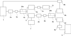
- FIG. 1 is a schematic diagram illustrating a separation device in one embodiment of the present disclosure.
- the gas separation method of the present disclosure includes: The method includes supplying a mixed gas containing two or more fluorocarbon gases having different molecular diameters to a porous membrane and separating one fluorocarbon gas selected from the two or more fluorocarbon gases;
- the porous membrane contains zeolite.
- This disclosure can provide a new method and device for separating fluorocarbons.
- Fluorocarbons are used as mixed gases for applications such as refrigerants, and attempts have been made to separate them by distillation, but distillation requires a large energy load and separation has been difficult due to azeotropy and other factors.
- distillation requires a large energy load and separation has been difficult due to azeotropy and other factors.
- the difference in molecular diameter between various fluorocarbons is small, it has not been easy to efficiently separate and regenerate them even by membrane separation.
- Fluorocarbon separation methods include, for example, a method using silicone resin as described in JP 01-42444 A, and a method using fluorine-based resin as described in Journal of Membrane Science 652 (2022) 120467.
- these methods use the dissolution-diffusion effect in which the gas to be separated dissolves in the membrane itself, and the effect of the pores in the separation medium is small.
- the separation method in the present disclosure differs from conventional separation methods in that fluorocarbon gas is passed through the pores of zeolite, which is the separation medium, and gas separation is performed by the molecular sieve effect. Therefore, according to the present disclosure, a new fluorocarbon separation method can be provided.
- the mixed gas contains two or more fluorocarbon gases, and the two or more fluorocarbon gases have different molecular diameters.
- the fluorocarbon gases may be typically gaseous fluorocarbons at 1 atmosphere and room temperature (25° C.).
- the above-mentioned fluorocarbons are compounds that contain a carbon atom and a fluorine atom bonded to the carbon atom, and representative examples include hydrochlorofluorocarbons, hydrofluorocarbons, and hydrofluoroolefins.
- hydrochlorofluorocarbons examples include chlorodifluoromethane and chlorotrifluoroethane.
- hydrofluorocarbons include hydrofluorocarbons with one carbon atom, such as difluoromethane; hydrofluorocarbons with two carbon atoms, such as difluoroethane (e.g., 1,1-difluoroethane, 1,2-difluoroethane, particularly 1,1-difluoroethane), trifluoroethane (e.g., 1,1,1-trifluoroethane, 1,1,2-trifluoroethane, particularly 1,1,1-trifluoroethane), tetrafluoroethane (e.g., 1,1,1,2-tetrafluoroethane, 1,1,2,2-tetrafluoroethane, particularly 1,1,1,2-tetrafluoroethane), and pentafluoroethane; and hydrofluorocarbons with three carbon atoms, such as tetrafluoropropene and hexafluoropropene.
- Hydrofluoroolefins include 2,3,3,3-tetrafluoropropene (HFO-1234yf), 1,3,3,3-tetrafluoropropene (HFO-1234ze), cis-1,1,1,4,4,4-hexafluoro-2-butene (HFO-1336mzz-Z; DR-2), trans-1,1,1,4,4,4-hexafluoro-2-butene (HFO-1336mzz-E), etc.
- the number of carbon atoms in the fluorocarbon may preferably be 1 to 5, more preferably 1 to 3.
- the content of fluorocarbons having 1 to 5 carbon atoms in the fluorocarbons contained in the mixed gas may be, for example, 80 mol% or more and 100 mol% or less, or 90 mol% or more and 100 mol% or less, relative to the total amount of fluorocarbons.
- the two or more fluorocarbon gases may include, for example, a fluorocarbon having one carbon atom and a fluorocarbon having two carbon atoms, preferably difluoromethane and pentafluoroethane, and more preferably difluoromethane and pentafluoroethane.
- the two or more fluorocarbon gases may include a fluorocarbon having one carbon atom and a fluorocarbon having three carbon atoms, preferably difluoromethane (R32) and tetrafluoropropene (particularly 2,3,3,3-tetrafluoropropene, R1234yf), and more preferably difluoromethane (R32) and tetrafluoropropene (particularly 2,3,3,3-tetrafluoropropene, R1234yf).
- difluoromethane R32
- tetrafluoropropene particularly 2,3,3,3-tetrafluoropropene, R1234yf
- the two or more fluorocarbon gases mentioned above have different molecular diameters.
- the molecular diameter of one type of fluorocarbon (fluorocarbon to be separated) contained in the mixed gas is preferably 2 ⁇ or more and 7 ⁇ or less, more preferably 3 ⁇ or more and 5 ⁇ or less, and even more preferably 3.2 ⁇ or more and 4.4 ⁇ or less.
- the molecular diameter of one type of fluorocarbon (fluorocarbon to be separated) contained in the mixed gas is preferably 2 ⁇ or more, more preferably 3 ⁇ or more, and even more preferably 3.2 ⁇ or more, and may be preferably 7 ⁇ or less, more preferably 5 ⁇ or less, and even more preferably 4.4 ⁇ or less.
- the molecular diameter of the other fluorocarbon contained in the mixed gas is, for example, more than 4 ⁇ , and may be 4.2 ⁇ or more and 10 ⁇ or less, or 4.4 ⁇ or more and 8 ⁇ or less.
- the molecular diameter of the carbon of the other fluorocarbon contained in the mixed gas may be, for example, more than 4 ⁇ , preferably 4.2 ⁇ or more, and may be, for example, 10 ⁇ or less, preferably 8 ⁇ or less.
- the difference in molecular diameter between one fluorocarbon and another fluorocarbon contained in the mixed gas may be preferably 0.1 ⁇ or more, more preferably 0.2 ⁇ or more and 3 ⁇ or less, and even more preferably 0.3 ⁇ or more and 2 ⁇ or less.
- the molecular diameter of the fluorocarbon gas may be a value calculated by the following formula, assuming that the shape of the fluorocarbon molecule is a hard sphere.
- d (ma/(3 ⁇ 2 1/2 ⁇ )) 1/2 ...(x1)
- d represents the molecular diameter
- m represents the mass of one molecule
- a represents the molecular velocity
- ⁇ represents the viscosity coefficient.
- ⁇ may be measured by the capillary method.
- the molecular diameter of the fluorocarbon contained in the mixed gas may be preferably 2 ⁇ or more and 10 ⁇ or less, more preferably 3 ⁇ or more and 8 ⁇ or less.
- the amount of the fluorocarbon 1 contained in the mixed gas permeated into the zeolite may be preferably 10 ⁇ 10 (mol/(m 2 ⁇ s ⁇ Pa) or more and 10 ⁇ 4 (mol/(m 2 ⁇ s ⁇ Pa) or less, more preferably 10 ⁇ 9 (mol/(m 2 ⁇ s ⁇ Pa) or more and 10 ⁇ 5 (mol/(m 2 ⁇ s ⁇ Pa) or less, and even more preferably 10 ⁇ 8 (mol/(m 2 ⁇ s ⁇ Pa) or more and 10 ⁇ 6 (mol/(m 2 ⁇ s ⁇ Pa) or less.
- the boiling points of the fluorocarbons contained in the mixed gas may be, for example, preferably between -80°C and -20°C, more preferably between -60°C and -30°C, and even more preferably between -50°C and -30°C, at 1 atmospheric pressure.
- the difference in boiling point between one fluorocarbon and another fluorocarbon contained in the mixed gas may be, for example, preferably between 0°C and 20°C, and more preferably between 0°C and 10°C, at 1 atmospheric pressure.
- the mixed gas may be an azeotropic or pseudo-azeotropic mixture of fluorocarbons.
- a specific fluorocarbon can be separated.
- Examples of such azeotropic or pseudo-azeotropic mixtures include mixtures in which the difference between the boiling point of the fluorocarbon to be separated and the boiling point of the other fluorocarbon is 1°C or more and 20°C or less, or even 3°C or more and 18°C or less.
- the fluorocarbon content in the mixed gas may be, for example, 80 mol % or more and 100 mol % or less, or 90 mol % or more and 100 mol % or less, based on the total amount of the mixed gas.
- the mixed gas may contain other compounds in addition to fluorocarbons.
- the boiling points of such other compounds may be, for example, -100°C or lower, or -150°C or lower.
- Such other compounds are typically contained in the mixture as gases.
- the other compounds mentioned above include nitrogen, oxygen, carbon dioxide, water, etc.
- the gas separation method of the present disclosure may include supplying a mixed gas containing difluoromethane and pentafluoroethane to a porous membrane to separate difluoromethane.
- the porous membrane is a membrane having a plurality of pores and contains zeolite.
- Zeolite is typically a porous metal oxide based on aluminosilicate, and any zeolite that has been assigned a framework code by the International Zeolite Society can be used.
- zeolites include A-type, ferrierite, MCM-22, ZSM-5, mordenite, L-type, Y-type, X-type, and beta-type, with A-type, CHA-type, and ZSM-5-type being preferred.
- the composition formula of the zeolite can be represented by Mn + 2/nO .( Al2O3 ).( SiO2 ) x.yH2O (wherein Mn + represents a metal cation having a valence of n, n represents an integer of 1 to 5, x represents an integer of 2 or more, for example, an integer of 2 to 10, and y represents an integer of 1 or more, for example, an integer of 1 to 50).
- the silica/alumina ratio in the zeolite may be preferably 1.25 or more and 100 or less, more preferably 5 or more and 50 or less, and even more preferably 10 or more and 30 or less.
- the silica/alumina ratio corresponds to x in the formula Mn + 2/nO . ( Al2O3 ).( SiO2 ) x.yH2O .
- the average pore diameter of the zeolite pores is preferably 2 ⁇ or more and 10 ⁇ or less, more preferably 3 ⁇ or more and 8 ⁇ or less, and even more preferably 3 ⁇ or more and 6 ⁇ or less.
- the separation efficiency of fluorocarbon gas can be improved.
- the average pore diameter of the pores in the above zeolite can be calculated by measuring the nitrogen gas adsorption/desorption isotherm and using the BJH method based on the pressure and the amount of nitrogen adsorption/desorption.
- the porosity of the above zeolite can be calculated by measuring the nitrogen gas adsorption/desorption isotherm and using the t-plot method based on the pressure and the amount of nitrogen adsorption/desorption.
- the thickness of the zeolite in the porous membrane may be preferably 0.1 ⁇ m or more and 100 ⁇ m or less, more preferably 0.5 ⁇ m or more and 50 ⁇ m or less, and even more preferably 1 ⁇ m or more and 10 ⁇ m or less.
- the porous membrane may include a zeolite and may further include a porous support.
- the porous membrane may include a porous support and a zeolite disposed on the porous support, and preferably includes a porous support and a porous zeolite membrane disposed on the porous support.
- the porous membrane includes a porous support, which can increase the stability of the porous membrane.
- the permeability of the mixed gas to the zeolite membrane can be increased, which is expected to further improve separation efficiency.
- the porous support may be either an inorganic porous support or an organic porous support.
- the inorganic porous support may preferably be composed of an inorganic material such as silica, alumina, zirconia, silicon carbide, silicon nitride, and mixtures thereof.
- the inorganic porous support may more preferably be a porous alumina support.
- the organic porous support may preferably be composed of a heat-resistant polymer.
- heat-resistant polymers include polysulfone, polyethersulfone, sulfonated polysulfone, sulfonated polyethersulfone, polyimide, polytetrafluoroethylene, polyvinylidene fluoride, and derivatives thereof.
- a heat-resistant polymer may be understood as a polymer having a glass transition temperature of 100°C or higher, and preferably a polymer having a glass transition temperature of 200°C or higher.
- the average pore size of the pores in the porous support may be preferably 10 nm or more and 500 nm or less, more preferably 15 nm or more and 300 nm or less, and even more preferably 20 nm or more and 200 nm or less.
- the porous membrane may further include a porous intermediate layer between the porous support and the zeolite.
- a porous intermediate layer By including such a porous intermediate layer, the continuity of the pore size between the zeolite and the porous support can be increased, and it is expected that the permeability of the mixed gas in the porous membrane can be further increased.
- the porous intermediate layer may be made of either an inorganic material or an organic material, and is preferably made of an inorganic material.
- inorganic materials include silica, alumina, zirconia, silicon carbide, silicon nitride, and mixtures thereof.
- organic materials are preferably heat-resistant polymeric materials, and specific examples include polysulfone, polyethersulfone, sulfonated polysulfone, sulfonated polyethersulfone, polyimide, polytetrafluoroethylene, polyvinylidene fluoride, and derivatives thereof.
- the average pore diameter of the pores in the porous intermediate layer may be preferably 0.5 nm or more and 30 nm or less, more preferably 0.7 nm or more and 20 nm or less, and even more preferably 1 nm or more and 10 nm or less.
- the average pore diameter of the porous membrane means the average pore diameter of the zeolite pores, and the pore diameter of the porous support or intermediate layer is not taken into consideration in measuring and calculating the average pore diameter of the porous membrane.
- An example of a method for producing such a porous membrane is the hydrothermal synthesis method.
- a raw material composition containing a silicon compound, an aluminum compound, a metal compound (but not including a silicon compound or an aluminum compound), water, and a structure directing agent used as necessary is subjected to a hydrothermal synthesis reaction to synthesize a zeolite. Seed crystals may be present during the hydrothermal synthesis reaction.
- the silicon compound may be silica sol, fumed silica, precipitated silica, aluminosilicate, alkoxysilane, etc.
- Examples of the aluminum compound that can be used include aluminum hydroxide, aluminum oxide, aluminum sulfate, aluminum chloride, aluminum nitrate, aluminosilicate, metallic aluminum, pseudoboehmite, alumina sol, and aluminum alkoxide.
- the metal compound may be lithium hydroxide, sodium hydroxide, potassium hydroxide, rubidium hydroxide, etc.
- the above-mentioned structure directing agents include structure directing agents that direct CHA-type zeolites, such as N,N,N-trialkyladamantane ammonium cation, N,N,N-trimethylbenzyl ammonium cation, N-alkyl-3-quinuclidinol cation, N,N,N-trialkylexoaminonorbornane cation, N,N,N-trialkylcyclohexyl ammonium cation, N,N,N-trimethylbenzyl ammonium cation, and N,N,N-trialkylcyclohexyl ammonium cation; structure directing agents that direct ZSM-5-type zeolites, such as tetrapropyl ammonium cation and tetraethyl ammonium cation; and structure directing agents that direct A-type zeolites, such as tetramethyl ammonium cation.
- the above silicon compounds, aluminum compounds, metal compounds, water, and structure directing agents, which are used as necessary, can be used appropriately depending on the desired zeolite structure.
- the temperature of the hydrothermal synthesis reaction may be preferably 80°C or higher and 200°C or lower, more preferably 100°C or higher and 180°C or lower, and even more preferably 120°C or higher and 160°C or lower.
- the above hydrothermal synthesis reaction is preferably carried out in a sealed container.
- the porous membrane when the porous membrane includes a porous support and/or an intermediate layer, the porous support and/or intermediate layer are coated with zeolite seed crystals, and the porous support and/or intermediate layer coated with the seed crystals are immersed in the raw material composition to perform hydrothermal synthesis, thereby producing the porous membrane.
- a mixed gas containing the fluorocarbon gas By supplying a mixed gas containing the fluorocarbon gas to the porous membrane, at least one type of fluorocarbon gas can permeate the pores of the porous membrane and separate the fluorocarbon gas.
- the fluorocarbon gas can be supplied to the porous membrane as a gas (vapor).
- this separation method allows the porous membrane to selectively transmit only a specific fluorocarbon gas, so that a specific fluorocarbon gas can be separated from a mixed gas containing two or more fluorocarbon gases.
- this separation method allows a fluorocarbon gas with one carbon atom to be separated from a mixed gas containing two or more fluorocarbon gases with different molecular diameters.
- the supply of the mixed gas to the porous membrane may be carried out, for example, by a column method.
- the column method can also be carried out by fixing the porous membrane to a container (column) and flowing the mixed gas into the container (column).
- the temperature during the above supply may be, for example, 5°C or higher and 500°C or lower, and may further be 10°C or higher and 300°C or lower.
- the pressure (gauge pressure) during the above supply may be 0.05 MPaG or higher and 20 MPaG or lower, and may be 0.1 MPaG or higher and 10 MPaG or lower.
- the flow rate of the mixed gas may be 0.001 kg/hour or more and 1,000 kg/hour/minute or less, 0.005 kg/hour or more and 500 kg/hour or less, or even 0.01 kg/hour or more and 100 kg/hour or more.
- the fluorocarbon gas separation method disclosed herein can also be understood as a fluorocarbon gas recovery method.
- the technical scope of the present disclosure also includes a composite material containing the porous membrane and a fluorocarbon.
- a composite material containing the porous membrane and a fluorocarbon.
- the fluorocarbon and porous membrane in this embodiment are the same as those in the first embodiment.
- the fluorocarbon preferably contains a fluorocarbon having one carbon atom, and more preferably contains one or more selected from chlorodifluoromethane and difluoromethane.
- the content of fluorocarbons with one carbon atom in the composite material is greater than the content of fluorocarbons with two or more carbon atoms, and more preferably, the total content of one or more selected from chlorodifluoromethane and difluoromethane is greater than the content of the other fluorocarbons.
- the composite material may contain a resin in addition to the fluorocarbon and the porous membrane.
- resins include acrylic resin, polyurethane resin, polyolefin resin, polyester resin, polyamide resin, polyimide resin, vinyl chloride resin, styrene resin, vinyl ether resin, polyvinyl alcohol resin, polycarbonate resin, polyethersulfone resin, and polysulfone resin.
- the composite material may contain additives such as emulsifiers, defoamers, surfactants, leveling agents, thickeners, viscoelasticity modifiers, defoamers, wetting agents, dispersants, preservatives, plasticizers, penetrants, fragrances, bactericides, miticides, fungicides, ultraviolet absorbers, antioxidants, antistatic agents, flame retardants, dyes, and pigments.
- additives such as emulsifiers, defoamers, surfactants, leveling agents, thickeners, viscoelasticity modifiers, defoamers, wetting agents, dispersants, preservatives, plasticizers, penetrants, fragrances, bactericides, miticides, fungicides, ultraviolet absorbers, antioxidants, antistatic agents, flame retardants, dyes, and pigments.
- the device of the present disclosure comprises: A porous membrane is provided,
- the porous membrane contains zeolite that separates a gas composition having an improved mixture ratio of one fluorocarbon gas from a mixed gas containing two or more fluorocarbon gases with different molecular diameters, or a single gas.
- a mixed gas containing two or more fluorocarbon gases with different molecular diameters is stored in a gas tank 1.
- the mixed gas is supplied to a first-stage separation module 4a through a pressure regulator 2a and a mass flow controller 3a.
- the pressure can be controlled by the pressure regulator 2a, but this is not a limitation.
- the pressure regulator 2a can also be omitted.
- the separation module 4a is equipped with a porous membrane 10a, and the mixed gas is supplied to the porous membrane 10a.
- pressure control may be performed by the retention side back pressure valve 6a.
- pressure reduction control can be performed by the retention side back pressure valve 6a.
- the retention side gas back pressure valve 6a can also be omitted.
- the gas that does not permeate the porous membrane 10a (hereinafter also referred to as the "first retained side gas") is recovered in the retained side gas recovery pipe 11 through the pressure regulator 2c.
- the first retained side gas may be recovered in the gas tank 1.
- the flow rate of the first retained side gas may be controlled by a mass flow controller.
- the gas that has permeated the porous membrane 10a (hereinafter also referred to as the "first permeated gas") has its permeation amount measured by a mass flow meter 5a, and is supplied to the second-stage separation module 4b via a pressure regulator 2b and a mass flow controller 3b.
- the pressure can be controlled by the pressure regulator 2b, but this is not limited to this embodiment.
- the pressure regulator 2b can also be omitted.
- the second-stage separation module 4b is equipped with a porous membrane 10b, and the first permeable gas is supplied to the porous membrane 10b.
- pressure control may be performed by the retention side gas back pressure valve 6b.
- pressure reduction control can be performed by the retention side back pressure valve 6a.
- the retention side gas back pressure valve 6b may be omitted.
- the gas that does not permeate the porous membrane 10b has its gas composition analyzed by the gas composition analyzer 8b and is then circulated to the gas tank 1.
- the second retained side gas may be separately recovered by a retained side gas recovery pipe.
- the second retained side gas may be separately circulated between the mass flow meter 5 and the pressure regulator 2b.
- the gas composition analyzer 8b can be omitted.
- the gas that has permeated the porous membrane 10b passes through the pressure regulator 2d, has its gas composition analyzed by the gas composition analyzer 8a, and is then recovered in the recovery pipe 9.
- the amount of gas that has permeated the porous membrane 10b may be measured using a mass flow meter.
- the gas composition analyzer 8a can be omitted.
- the separation device may be one-stage, three-stage, four-stage or more.
- the first permeable gas may be recovered by a recovery pipe, and the first retained gas may be recovered by a retained gas recovery pipe or circulated to the gas tank 1.
- the permeable gas that has permeated the n-1th separation module may be supplied to the separation module via a pressure regulator and a mass flow controller, and separated through a porous membrane contained in the separation module into an nth permeable gas that has permeated the porous membrane, and an nth retained gas that has not permeated the porous membrane.
- Gas separation can be performed by recovering the nth permeable gas after gas composition analysis, which may be performed as necessary.
- the nth retained gas may be circulated to the gas tank 1 or recovered in the retained gas recovery pipe after gas analysis, which may be performed as necessary.
- Example 1 Fluorocarbon gas adjusted to a predetermined pressure and flow rate using a pressure regulator and a mass flow controller (MFC) was passed through a membrane module equipped with a ZSM-5 type zeolite membrane (Esep). The pressure regulator and mass flow meter (MFM) were used to confirm the pressure and flow rate on the permeation side and retention side. A vacuum pump was connected to the permeation side, and measurements were performed under reduced pressure conditions as necessary. The permeability of the single component gas was calculated from the flow rate.
- MFC mass flow controller
- the fluorocarbons used were R32 (difluoromethane) and R125 (1,1,1,2,2-pentafluoroethane).
- the molecular diameter of R32 is 3.9 ⁇ , and that of R125 is 4.4 ⁇ .
- the zeolite used was ZSM-5 type (pore size 5.5 ⁇ ).
- the pore size of the zeolite membrane, the temperature and supply side differential pressure during measurement, the permeation amount (R32 and R125), and the permeability ratio are shown in the table below.
- Examples 1 to 3 are examples of the present disclosure, and are examples in which fluorocarbons were supplied to a porous membrane containing zeolite.
- the permeation amount of R32 difluoromethane
- R125 permeation amount of R125 (1,1,1,2,2-pentafluoroethane)
- the ratio of the permeation amount of R32 to the permeation amount of R125 was 6 to 28 times. From this, it can be said that a mixed gas containing two or more types of fluorocarbon gases can be supplied to a porous membrane containing zeolite, and one type of fluorocarbon gas selected from the two or more types of fluorocarbon gases can be separated.
Landscapes
- Chemical & Material Sciences (AREA)
- Chemical Kinetics & Catalysis (AREA)
- Engineering & Computer Science (AREA)
- Inorganic Chemistry (AREA)
- Analytical Chemistry (AREA)
- General Chemical & Material Sciences (AREA)
- Oil, Petroleum & Natural Gas (AREA)
- Crystallography & Structural Chemistry (AREA)
- Manufacturing & Machinery (AREA)
- Life Sciences & Earth Sciences (AREA)
- Geology (AREA)
- Separation Using Semi-Permeable Membranes (AREA)
Abstract
本開示は、フルオロカーボンの新たな分離方法を提供することを目的とする。 互いに分子径が異なる2種以上のフルオロカーボンガスを含む混合ガスを、多孔膜に供給して、前記2種以上のフルオロカーボンガスから選ばれる1種のフルオロカーボンガスの混合比を向上させたガス組成物あるいは単一ガスを分離することを含み、 前記多孔膜は、ゼオライトを含む、フルオロカーボンガスの分離方法。
Description
本開示は、ガス分離方法および分離装置に関する。
フルオロカーボンの分離方法として、フルオロカーボンの混合物を蒸留する方法が知られている。特許文献1には、2,3,3,3-テトラフルオロプロペンおよびヘキサフルオロプロペンを含む混合物と、抽出溶剤とを混合して抽出用混合物を得た後、かかる抽出用混合物を蒸留して、ヘキサフルオロプロペンを主成分とする留出物と、2,3,3,3-テトラフルオロプロペンを含む留出物とを得ることが記載されている。
本開示は、フルオロカーボンガスの新たな分離方法を提供することを目的とする。
本開示は、以下の態様を提供する。
[1]
互いに分子径が異なる2種以上のフルオロカーボンガスを含む混合ガスを、多孔膜に供給して、前記2種以上のフルオロカーボンガスから選ばれる1種のフルオロカーボンガスの混合比を向上させたガス組成物あるいは単一ガスを分離することを含み、
前記多孔膜は、ゼオライトを含む、フルオロカーボンガスの分離方法。
[2]
前記多孔膜の平均細孔径は、2Å以上10Å以下である、[1]に記載のフルオロカーボンガスの分離方法。
[3]
前記多孔膜は、水熱合成法により形成される多孔膜を含む、[1]または[2]に記載のフルオロカーボンガスの分離方法。
[4]
前記ゼオライトは、A型ゼオライト、CHA型ゼオライトおよびZSM-5型ゼオライトからなる群より選ばれる1種または2種以上を含む、[1]~[3]のいずれか1つに記載のフルオロカーボンガスの分離方法。
[5]
前記1種のフルオロカーボンガスの分子径は、2Å以上7Å以下である、[1]~[4]のいずれか1つに記載のフルオロカーボンガスの分離方法。
[6]
前記1種のフルオロカーボンガスの分子径と、それ以外のフルオロカーボンガスの分子径との差は、0.1Å以上3Å以下である、[1]~[5]のいずれか1つに記載のフルオロカーボンガスの分離方法。
[7]
前記混合ガスの前記多孔膜への供給は、20℃以上300℃以下の温度で実施される、[1]~[6]のいずれか1つに記載のフルオロカーボンガスの分離方法。
[8]
前記混合ガスの前記多孔膜への供給は、0.1MPa以上の差圧下で実施される、[1]~[7]のいずれか1つに記載のフルオロカーボンガスの分離方法。
[9]
前記多孔膜は、多孔質支持体をさらに含む、[1]~[8]のいずれか1つに記載のフルオロカーボンガスの分離方法。
[10]
前記混合ガスは、ジフルオロメタンおよびペンタフルオロエタンを含む、[1]~[10]のいずれか1つに記載のフルオロカーボンガスの分離方法。
[11]
前記混合ガスを前記多孔膜に供給することは、前記混合ガスの少なくとも一部を前記多孔膜に透過させることを含む、[1]~[10]のいずれか1つに記載のフルオロカーボンガスの分離方法。
[12]
多孔膜を備え、
前記多孔膜は、分子径が異なる2種以上のフルオロカーボンガスを含む混合ガスから1種のフルオロカーボンガスの混合比を向上させたガス組成物あるいは単一ガスを分離するゼオライトを含む、装置。
[1]
互いに分子径が異なる2種以上のフルオロカーボンガスを含む混合ガスを、多孔膜に供給して、前記2種以上のフルオロカーボンガスから選ばれる1種のフルオロカーボンガスの混合比を向上させたガス組成物あるいは単一ガスを分離することを含み、
前記多孔膜は、ゼオライトを含む、フルオロカーボンガスの分離方法。
[2]
前記多孔膜の平均細孔径は、2Å以上10Å以下である、[1]に記載のフルオロカーボンガスの分離方法。
[3]
前記多孔膜は、水熱合成法により形成される多孔膜を含む、[1]または[2]に記載のフルオロカーボンガスの分離方法。
[4]
前記ゼオライトは、A型ゼオライト、CHA型ゼオライトおよびZSM-5型ゼオライトからなる群より選ばれる1種または2種以上を含む、[1]~[3]のいずれか1つに記載のフルオロカーボンガスの分離方法。
[5]
前記1種のフルオロカーボンガスの分子径は、2Å以上7Å以下である、[1]~[4]のいずれか1つに記載のフルオロカーボンガスの分離方法。
[6]
前記1種のフルオロカーボンガスの分子径と、それ以外のフルオロカーボンガスの分子径との差は、0.1Å以上3Å以下である、[1]~[5]のいずれか1つに記載のフルオロカーボンガスの分離方法。
[7]
前記混合ガスの前記多孔膜への供給は、20℃以上300℃以下の温度で実施される、[1]~[6]のいずれか1つに記載のフルオロカーボンガスの分離方法。
[8]
前記混合ガスの前記多孔膜への供給は、0.1MPa以上の差圧下で実施される、[1]~[7]のいずれか1つに記載のフルオロカーボンガスの分離方法。
[9]
前記多孔膜は、多孔質支持体をさらに含む、[1]~[8]のいずれか1つに記載のフルオロカーボンガスの分離方法。
[10]
前記混合ガスは、ジフルオロメタンおよびペンタフルオロエタンを含む、[1]~[10]のいずれか1つに記載のフルオロカーボンガスの分離方法。
[11]
前記混合ガスを前記多孔膜に供給することは、前記混合ガスの少なくとも一部を前記多孔膜に透過させることを含む、[1]~[10]のいずれか1つに記載のフルオロカーボンガスの分離方法。
[12]
多孔膜を備え、
前記多孔膜は、分子径が異なる2種以上のフルオロカーボンガスを含む混合ガスから1種のフルオロカーボンガスの混合比を向上させたガス組成物あるいは単一ガスを分離するゼオライトを含む、装置。
本発明によればフルオロカーボンガスの新たな分離方法を提供し得る。
(第一実施形態:ガス分離方法)
本開示のガス分離方法は、
互いに分子径が異なる2種以上のフルオロカーボンガスを含む混合ガスを、多孔膜に供給して、前記2種以上のフルオロカーボンガスから選ばれる1種のフルオロカーボンガスを分離することを含み、
前記多孔膜は、ゼオライトを含む。
本開示のガス分離方法は、
互いに分子径が異なる2種以上のフルオロカーボンガスを含む混合ガスを、多孔膜に供給して、前記2種以上のフルオロカーボンガスから選ばれる1種のフルオロカーボンガスを分離することを含み、
前記多孔膜は、ゼオライトを含む。
本開示は、フルオロカーボンの新たな分離方法および分離装置を提供することができる。フルオロカーボンは混合ガスとして冷媒などの用途に用いられており、蒸留による分離が試みられているが、蒸留はエネルギー負荷が大きく、また、共沸などのために分離が困難であった。加えて、各種のフルオロカーボンは、分子径の差が小さいため膜分離でも効率的に分離再生することが容易ではなかった。
フルオロカーボンの分離方法としては、例えば、特開平1-42444号公報に記載されるように、シリコーン樹脂を用いた方法、Journal of Membrane Science 652 (2022) 120467に記載されるように、フッ素系樹脂を用いる方法も知られている。しかしながら、これらの方法では、分離対象となるガスが膜そのものに溶け込む溶解拡散効果を利用して分離しており、分離媒体の細孔の影響は小さい。本開示における分離方法は、分離媒体であるゼオライトの細孔にフルオロカーボンガスを透過させ、分子篩効果によりガス分離を実施している点で、従来の分離方法とは異なる。そのため、本開示によれば、フルオロカーボンの新たな分離方法を提供することができる。
(混合ガス)
上記混合ガスは、2種以上のフルオロカーボンガスを含み、該2種以上のフルオロカーボンガスは、互いに分子径が異なる。フルオロカーボンガスは、代表的には、1気圧、室温(25℃)において、ガス状の(気体状の)フルオロカーボンであり得る。
上記混合ガスは、2種以上のフルオロカーボンガスを含み、該2種以上のフルオロカーボンガスは、互いに分子径が異なる。フルオロカーボンガスは、代表的には、1気圧、室温(25℃)において、ガス状の(気体状の)フルオロカーボンであり得る。
上記フルオロカーボンは、炭素原子と該炭素原子に結合するフッ素原子とを含む化合物であり、代表的には、ハイドロクロロフルオロカーボン、ハイドロフルオロカーボン、ハイドロフルオロオレフィンが挙げられる。
上記ハイドロクロロフルオロカーボンとしては、クロロジフルオロメタン、クロロトリフルオロエタン等が挙げられる。
上記ハイドロフルオロカーボンとしては、ジフルオロメタン等の炭素数1のハイドロフルオロカーボン;ジフルオロエタン(例えば、1,1-ジフルオロエタン、1,2-ジフルオロエタン、特に、1,1-ジフルオロエタン)、トリフルオロエタン(例えば、1,1,1-トリフルオロエタン、1,1,2-トリフルオロエタン、特に、1,1,1-トリフルオロエタン)、テトラフルオロエタン(例えば、1,1,1,2-テトラフルオロエタン、1,1,2,2-テトラフルオロエタン、特に1,1,1,2-テトラフルオロエタン)、ペンタフルオロエタン等の炭素数2のハイドロフルオロカーボン;テトラフルオロプロペン、ヘキサフルオロプロペン等の炭素数3のハイドロフルオロカーボン等が挙げられる。
ハイドロフルオロオレフィンとしては、2,3,3,3-テトラフルオロプロペン(HFO-1234yf)、1,3,3,3-テトラフルオロプロペン(HFO-1234ze)、シス-1,1,1,4,4,4-ヘキサフルオロ-2-ブテン(HFO-1336mzz-Z;DR-2)、トランス-1,1,1,4,4,4-ヘキサフルオロ-2-ブテン(HFO-1336mzz-E)等が挙げられる。
上記フルオロカーボンの炭素数は、好ましくは1~5、より好ましくは1~3であり得る。
上記混合ガスに含まれるフルオロカーボン中、炭素数1~5のフルオロカーボンの含有率は、フルオロカーボン全体量に対して、例えば、80モル%以上100モル%以下であってよく、90モル%以上100モル%以下であってよい。
上記2種以上のフルオロカーボンガスは、例えば、炭素数1のフルオロカーボンおよび炭素数2のフルオロカーボンを含み得、好ましくは、ジフルオロメタンおよびペンタフルオロエタンを含み得、より好ましくは、ジフルオロメタンおよびペンタフルオロエタンからなる。別の態様において、上記2種以上のフルオロカーボンガスは、炭素数1のフルオロカーボンおよび炭素数3のフルオロカーボンを含み得、好ましくは、ジフルオロメタン(R32)およびテトラフルオロプロペン(特に、2,3,3,3-テトラフルオロプロペン、R1234yf)を含み得、より好ましくは、ジフルオロメタン(R32)およびテトラフルオロプロペン(特に、2,3,3,3-テトラフルオロプロペン、R1234yf)からなる。
上記2種以上のフルオロカーボンガスは、互いに分子径が異なる。
一の態様において、上記混合ガスに含まれる1種のフルオロカーボン(分離対象であるフルオロカーボン)の分子径は、好ましくは2Å以上7Å以下、より好ましくは3Å以上5Å以下、さらに好ましくは3.2Å以上4.4Å以下である。また、上記混合ガスに含まれる1種のフルオロカーボン(分離対象であるフルオロカーボン)の分子径は、好ましくは2Å以上、より好ましくは3Å以上、さらに好ましくは3.2Å以上であり、好ましくは7Å以下、より好ましくは5Å以下、さらに好ましくは4.4Å以下であり得る。
同じ態様において、上記混合ガスに含まれる別のフルオロカーボンの分子径は、例えば4Å超であり、4.2Å以上10Å以下であってよく、4.4Å以上8Å以下であってよい。また、上記混合ガスに含まれる別のフルオロカーボンのカーボンの分子径は、例えば4Å超、好ましくは4.2Å以上であり、例えば10Å以下、好ましくは8Å以下であり得る。
同じ態様において、上記混合ガスに含まれる1のフルオロカーボンと、別のフルオロカーボンの分子径の差は、好ましくは0.1Å以上、より好ましくは0.2Å以上3Å以下、さらに好ましくは0.3Å以上2Å以下であり得る。
上記フルオロカーボンガスの分子径は、フルオロカーボン分子の形状を剛体球と仮定し、以下の式により算出される値であり得る。
d=(ma/(3×21/2ηπ))1/2 …(x1)
ただし、式(x1)中、dは分子径、mは分子1個の質量、aは分子速度、ηは粘性係数を表す。
aは、以下の式により算出される。
a=(γRT/M)1/2 …(x2)
ここで、γは比熱比であり、1.333として近似する。また、Rは気体定数、Tは絶対温度であり、Mは、モル分子質量である。
また、ηは、毛細管法により測定してよい。
d=(ma/(3×21/2ηπ))1/2 …(x1)
ただし、式(x1)中、dは分子径、mは分子1個の質量、aは分子速度、ηは粘性係数を表す。
aは、以下の式により算出される。
a=(γRT/M)1/2 …(x2)
ここで、γは比熱比であり、1.333として近似する。また、Rは気体定数、Tは絶対温度であり、Mは、モル分子質量である。
また、ηは、毛細管法により測定してよい。
上記混合ガスに含まれるフルオロカーボンの分子径は、好ましくは2Å以上10Å以下、より好ましくは3Å以上8Å以下であり得る。
上記混合ガスに含まれる1のフルオロカーボンのゼオライトへの透過量は、好ましくは10-10(mol/(m2・s・Pa)以上10-4(mol/(m2・s・Pa)以下、より好ましくは10-9(mol/(m2・s・Pa)以上10-5(mol/(m2・s・Pa)以下、さらに好ましくは10-8(mol/(m2・s・Pa)以上10-6(mol/(m2・s・Pa)以下であり得る。
上記混合ガスに含まれるフルオロカーボンの沸点は、1気圧において、例えば、好ましくは-80℃以上-20℃以下、より好ましくは-60℃以上-30℃以下、さらに好ましくは-50℃以上-30℃以下であり得る。また、上記混合ガスに含まれる1のフルオロカーボンと別のフルオロカーボンの沸点の差は、1気圧において、例えば、好ましくは0℃以上20℃以下、より好ましくは0℃以上10℃以下であり得る。
上記混合ガスは、フルオロカーボンの共沸混合物または擬共沸混合物であってよい。本開示のガス分離方法によれば、共沸混合物または擬共沸混合物であっても、特定のフルオロカーボンを分離し得る。かかる共沸混合物または擬共沸混合物としては、例えば、分離対象のフルオロカーボンの沸点と、それ以外のフルオロカーボンの沸点との差が、1℃以上20℃以下、さらに3℃以上18℃以下である混合物が挙げられる。
上記混合ガス中、フルオロカーボンの含有率は、混合ガス全体量に対して、例えば、80モル%以上100モル%以下であってよく、90モル%以上100モル%以下であってよい。
上記混合ガスは、フルオロカーボン以外に、他の化合物を含んでいてもよい。かかる他の化合物の沸点は、例えば-100℃以下であってよく、-150℃以下であってよい。かかる他の化合物は、代表的には、気体(ガス)として上記混合物に含まれる。
上記他の化合物としては、窒素、酸素、二酸化炭素、水等が挙げられる。
一の態様において、本開示のガス分離方法は、ジフルオロメタンおよびペンタフルオロエタンを含む混合ガスを、多孔膜に供給して、ジフルオロメタンを分離することを含み得る。
(多孔膜)
上記多孔膜は、複数の細孔を有する膜であり、ゼオライトを含む。ゼオライトは、代表的には、アルミノケイ酸を基礎とした多孔質金属酸化物であり、国際ゼオライト学会により骨格コードが付与されているゼオライトを用いることができる。
(多孔膜)
上記多孔膜は、複数の細孔を有する膜であり、ゼオライトを含む。ゼオライトは、代表的には、アルミノケイ酸を基礎とした多孔質金属酸化物であり、国際ゼオライト学会により骨格コードが付与されているゼオライトを用いることができる。
上記ゼオライトとしては、具体的には、A型、フェリエライト、MCM-22、ZSM-5、モルデナイト、L型、Y型、X型、ベータ型等が挙げられ、好ましくは、A型、CHA型、ZSM-5型が挙げられる。
一態様において、上記ゼオライトの組成式は、Mn+
2/nO・(Al2O3)・(SiO2)x・yH2Oで表され得る(式中、Mn+は、n価の金属カチオンを表し、nは1~5の整数を表し、xは2以上の整数、例えば2~10の整数を表し、yは1以上の整数、例えば1~50の整数を表す)。
上記ゼオライトにおけるシリカ/アルミナ比は、好ましくは1.25以上100以下、より好ましくは5以上50以下、さらに好ましくは10以上30以下であり得る。上記シリカ/アルミナ比は、上記式Mn+
2/nO・(Al2O3)・(SiO2)x・yH2Oにおけるxに該当する。
上記ゼオライトの細孔の平均細孔径は、好ましくは2Å以上10Å以下、より好ましくは3Å以上8Å以下、さらに好ましくは3Å以上6Å以下であり得る。ゼオライトの細孔の平均細孔径がかかる範囲にあることで、フルオロカーボンガスの分離効率が高められ得る。
上記ゼオライトにおける細孔の平均細孔径は、窒素ガスの吸脱着等温線を測定し、圧力と窒素吸脱着量に基づき、BJH法により算出できる。
上記ゼオライトの気孔率は、窒素ガスの吸脱着等温線を測定し、圧力と窒素吸脱着量に基づき、t-plot法により算出できる。
上記多孔膜におけるゼオライトの厚さは、好ましくは0.1μm以上100μm以下、より好ましくは0.5μm以上50μm以下、さらに好ましくは1μm以上10μm以下であり得る。
上記多孔膜は、ゼオライトを含み、多孔質支持体をさらに含んでいてもよい。かかる態様において、上記多孔膜は、多孔質支持体と、該多孔質支持体上に配置されたゼオライトとを含み得、好ましくは、多孔質支持体と、該多孔質支持体上に配置された多孔質のゼオライト膜とを含み得る。
多孔膜が、多孔質支持体を含むことで、多孔膜の安定性を高め得る。また、多孔膜に混合ガスを供給する際、ゼオライト膜への混合ガスの透過率が高められ得るため、分離効率をより高め得ることが期待される。
上記多孔質支持体は、無機多孔質支持体および有機多孔質支持体のいずれであってもよい。
かかる無機多孔質支持体は、好ましくは、シリカ、アルミナ、ジルコニア、炭化ケイ素、窒化ケイ素、および、これらの混合物等の無機材料で構成され得る。上記無機多孔質支持体は、より好ましくは、多孔質アルミナ支持体であり得る。
上記有機多孔質支持体は、好ましくは、耐熱性高分子で構成され得る。かかる耐熱性高分子としては、ポリスルホン、ポリエーテルスルホン、スルホン化ポリスルホン、スルホン化ポリエーテルスルホン、ポリイミド、ポリテトラフルオロエチレン、ポリフッ化ビニリデン、および、これらの誘導体が挙げられる。本開示において、耐熱性高分子は、ガラス転移温度が100℃以上の高分子と理解してよく、好ましくは、ガラス転移温度が200℃以上の高分子と理解してよい。
上記多孔質支持体における細孔の平均細孔径は、好ましくは10nm以上500nm以下、より好ましくは15nm以上300nm以下、さらに好ましくは20nm以上200nm以下であり得る。
上記多孔膜は、上記多孔質支持体と、上記ゼオライトとの間に、多孔質中間層をさらに含んでいてもよい。かかる多孔質中間層を含むことで、上記ゼオライトと上記多孔質支持体の細孔径の連続性が高められ得、多孔膜中の混合ガスの透過率をより高め得ることが期待される。
かかる多孔質中間層は、無機材料および有機材料のいずれで構成されていてもよく、好ましくは、無機材料で構成される。かかる無機材料としては、シリカ、アルミナ、ジルコニア、炭化ケイ素、窒化ケイ素、および、これらの混合物が挙げられる。有機材料としては、耐熱性高分子材料が好ましく、具体的には、ポリスルホン、ポリエーテルスルホン、スルホン化ポリスルホン、スルホン化ポリエーテルスルホン、ポリイミド、ポリテトラフルオロエチレン、ポリフッ化ビニリデン、および、これらの誘導体が挙げられる。
上記多孔質中間層における細孔の平均細孔径は、好ましくは0.5nm以上30nm以下、より好ましくは0.7nm以上20nm以下、さらに好ましくは1nm以上10nm以下であり得る。
なお、本開示では、上記多孔膜が多孔質支持体または中間層を含む場合において、多孔膜の平均細孔径は、上記ゼオライトの細孔の平均細孔径を意味し、多孔質支持体または中間層の細孔径は、多孔膜の平均細孔径の測定および算出において、考慮しない。
かかる多孔膜の製造方法としては、水熱合成法が挙げられる。代表的には、水熱合成法では、ケイ素化合物、アルミニウム化合物、金属化合物(ただし、ケイ素化合物およびアルミニウム化合物を含まない)、水及び必要に応じて用いる構造指向剤を含む原料組成物を、水熱合成反応に供することで、ゼオライトが合成され得る。水熱合成反応の際、種結晶を共存させてもよい。
上記ケイ素化合物としては、シリカゾル、ヒュームドシリカ、沈降法シリカ、アルミノシリケート、アルコキシシラン等を用いることができる。
上記アルミニウム化合物としては、水酸化アルミニウム、酸化アルミニウム、硫酸アルミニウム、塩化アルミニウム、硝酸アルミニウム、アルミノシリケート、金属アルミニウム、擬ベーマイト、アルミナゾル、アルミニウムアルコキシド等を用いることができる。
上記金属化合物としては、水酸化リチウム、水酸化ナトリウム、水酸化カリウム、水酸化ルビジウム等を用いることができる。
上記構造指向剤としては、N,N,N-トリアルキルアダマンタンアンモニウムカチオン、N,N,N-トリメチルベンジルアンモニウムカチオン、N-アルキル-3-キヌクリジノールカチオン、N,N,N-トリアルキルエキソアミノノルボルナンカチオン及びN,N,N-トリアルキルシクロヘキシルアンモニウムカチオン、N,N,N-トリメチルベンジルアンモニウムカチオン、N,N,N-トリアルキルシクロヘキシルアンモニウムカチオン等のCHA型ゼオライトを指向する構造指向剤;テトラプロピルアンモニウムカチオン、テトラエチルアンモニウムカチオン等のZSM-5型を指向する構造指向剤;テトラメチルアンモニウムカチオン等のA型を指向する構造指向剤等を用いることができる。
上記ケイ素化合物、アルミニウム化合物、金属化合物、水及び必要に応じて用いる構造指向剤は、目的とするゼオライトの構造に応じて適宜用いることができる。
上記水熱合成反応の温度は、好ましくは80℃以上200℃以下、より好ましくは100℃以上180℃以下、さらに好ましくは120℃以上160℃以下であり得る。
上記水熱合成反応は、密閉容器中で実施されることが好ましい。
一の態様において、上記多孔膜が、多孔質支持体および/または中間層を含む場合、多孔質支持体および/または中間層上にゼオライトの種結晶を塗布し、かかる種結晶を塗布した多孔質支持体および/または中間層を上記原料組成物中に浸漬させて水熱合成することで、多孔膜を製造できる。
(接触方法)
上記フルオロカーボンガスを含む混合ガスを上記多孔膜に供給することにより、少なくとも1種のフルオロカーボンガスが多孔膜の細孔を透過し、該フルオロカーボンガスを分離し得る。フルオロカーボンガスは、ガス(気体)として多孔膜に供給され得る。
上記フルオロカーボンガスを含む混合ガスを上記多孔膜に供給することにより、少なくとも1種のフルオロカーボンガスが多孔膜の細孔を透過し、該フルオロカーボンガスを分離し得る。フルオロカーボンガスは、ガス(気体)として多孔膜に供給され得る。
一の態様において、かかる分離方法によれば、上記多孔膜が特定のフルオロカーボンガスのみを選択的に透過させ得るため、2種以上のフルオロカーボンガスを含む混合ガスから、特定のフルオロカーボンガスを分離し得る。好ましい態様において、かかる分離方法によれば、分子径が異なる2種以上のフルオロカーボンガスを含む混合ガスから、炭素数1のフルオロカーボンガスを分離し得る。
上記多孔膜への混合ガスの供給は、例えば、カラム法により実施してよい。また、カラム法は、多孔膜を容器(カラム)に固定し、混合ガスを該容器(カラム)内に流すことにより実施できる。
一の態様において、上記供給の際の温度は、例えば5℃以上500℃以下であってよく、さらに10℃以上300℃以下であってよい。また、上記供給の際の圧力(ゲージ圧)は、0.05MPaG以上20MPaG以下であってよく、0.1MPaG以上10MPaG以下であってよい。供給の際の圧力が上記範囲にあることで、フルオロカーボンが多孔膜を透過しやすくなり、分離効率が向上し得るとともに、多孔膜の細孔構造を保持しうる。
上記混合ガスの流量は、0.001kg/時間以上1,000kg/時間/分以下であってよく、0.005kg/時間以上500kg/時間以下、さらに0.01kg/時間以上100kg/時間であってよい。
上記多孔膜を透過したフルオロカーボンガスのみを回収することで、特定のフルオロカーボンガスを回収することができる。かかる態様において、本開示のフルオロカーボンガスの分離方法は、フルオロカーボンガスの回収方法とも理解され得る。
(第二実施形態:複合材料)
上記多孔膜と、フルオロカーボンとを含む複合材料も本開示の技術的範囲に含まれる。上記混合ガスを上記多孔膜に供給することにより、上記混合ガスに含まれるフルオロカーボンの少なくとも一部が上記多孔膜に残留し得、かかる複合材料が製造され得る。
上記多孔膜と、フルオロカーボンとを含む複合材料も本開示の技術的範囲に含まれる。上記混合ガスを上記多孔膜に供給することにより、上記混合ガスに含まれるフルオロカーボンの少なくとも一部が上記多孔膜に残留し得、かかる複合材料が製造され得る。
本実施形態におけるフルオロカーボンおよび多孔膜は、第一実施形態におけるフルオロカーボンおよび多孔膜と同意義である。
かかる複合材料において、上記フルオロカーボンは、好ましくは、炭素数1のフルオロカーボンを含み、より好ましくは、クロロジフルオロメタンおよびジフルオロメタンから選ばれる1種または2種以上を含み得る。
好ましい態様において、上記複合材料における炭素数1のフルオロカーボンの含有量は、炭素数2以上のフルオロカーボンの含有量よりも大きく、より好ましくは、クロロジフルオロメタンおよびジフルオロメタンから選ばれる1種または2種以上の合計の含有量は、それ以外のフルオロカーボンの含有量よりも大きい。
上記複合材料は、上記フルオロカーボンおよび上記多孔膜の他に、樹脂を含んでいてもよい。かかる樹脂としては、樹脂としては、アクリル樹脂、ポリウレタン樹脂、ポリオレフィン樹脂、ポリエステル樹脂、ポリアミド樹脂、ポリイミド樹脂、塩化ビニル樹脂、スチレン樹脂、ビニルエーテル樹脂、ポリビニルアルコール樹脂、ポリカーボネート樹脂、ポリエーテルスルホン樹脂およびポリスルホン樹脂等が挙げられる。
上記複合材料は、乳化剤、消泡剤、界面活性剤、レベリング剤、増粘剤、粘弾性調整剤、消泡剤、湿潤剤、分散剤、防腐剤、可塑剤、浸透剤、香料、殺菌剤、殺ダニ剤、防かび剤、紫外線吸収剤、酸化防止剤、帯電防止剤、難燃剤、染料、顔料等の添加剤を含んでいてもよい。
(第三実施形態:分離装置)
以下、本開示の1つの実施形態における分離装置について説明するが、本開示はかかる態様に限定されない。
以下、本開示の1つの実施形態における分離装置について説明するが、本開示はかかる態様に限定されない。
本開示の装置は、
多孔膜を備え、
前記多孔膜は、分子径が異なる2種以上のフルオロカーボンガスを含む混合ガスから1種のフルオロカーボンガスの混合比を向上させたガス組成物あるいは単一ガスを分離するゼオライトを含む。
多孔膜を備え、
前記多孔膜は、分子径が異なる2種以上のフルオロカーボンガスを含む混合ガスから1種のフルオロカーボンガスの混合比を向上させたガス組成物あるいは単一ガスを分離するゼオライトを含む。
図1に、本開示の分離装置の一例として、2段式の分離装置を模式的に示して説明する。
図1の分離装置では、ガスタンク1に分子径が異なる2種以上のフルオロカーボンガスを含む混合ガスが貯留される。混合ガスは、圧力調整器2aおよびマスフローコントローラー3aを通じて、1段階目の分離モジュール4aに供給される。一態様において、圧力調整器2aにより加圧制御され得るが、かかる態様に限定されない。圧力調整器2aは省略することも可能である。
分離モジュール4aは、多孔膜10aを備えており、混合ガスは、かかる多孔膜10aに供給される。この際、保持側背圧弁6aによって、圧力制御を実施してもよい。代表的には、保持側背圧弁6aによって、減圧制御され得る。保持側ガス背圧弁6aは、省略することも可能である。
多孔膜10aを透過しなかったガス(以下、「第1保持側ガス」ともいう)は、圧力調整器2cを通じて、保持側ガス回収配管11に回収される。第1保持側ガスは、ガスタンク1に回収してもよい。一態様において、第1保持側ガスの流量を、マスフローコントローラーにより制御してもよい。
2段式の分離装置では、多孔膜10aを透過したガス(以下、「第1透過ガス」ともいう)は、マスフローメーター5aによって透過量を計測し、圧力調整器2bおよびマスフローコントローラー3bを通じて、2段階目の分離モジュール4bに供給される。一態様において、圧力調整器2bにより加圧制御され得るが、かかる態様に限定されない。圧力調整器2bは省略することも可能である。
2段階目の分離モジュール4bは、多孔膜10bを備えており、第1透過ガスは、かかる多孔膜10bに供給される。この際、保持側ガス背圧弁6bによって、圧力制御を実施してもよい。代表的には、保持側背圧弁6aによって、減圧制御され得る。保持側ガス背圧弁6bは、省略することも可能である。
第1透過ガスのうち、多孔膜10bを透過しなかったガス(以下、「第2保持側ガス」ともいう)は、ガス組成分析計8bでガス組成を分析した後、ガスタンク1に循環させる。別の態様において、第2保持側ガスは、別途、保持側ガス回収配管により回収してもよい。さらに別の態様において、第2保持側ガスは、別途、マスフローメーター5と圧力調整器2bの間に循環させてもよい。一態様において、ガス組成分析計8bは省略可能である。
第1透過ガスのうち、多孔膜10bを透過したガス(以下、「第2透過ガス」ともいう)は、圧力調整器2dを通じ、ガス組成分析計8aでガス組成を分析した後、回収配管9に回収される。一態様において、マスフローメーターを用い、多孔膜10bを透過したガスの透過量を測定してよい。また、一態様において、ガス組成分析計8aは、省略可能である。
本実施形態では、2段式の分離装置について説明したが、これに限定されず、適宜変更を加えることが可能であり、例えば、1段式、3段式または4段式以上の分離装置としてもよい。1段式の場合、第1透過ガスを回収配管で回収してよく、第1保持側ガスを保持側ガス回収配管により回収またはガスタンク1に循環させてよい。
n段式の場合(nは、3以上)、n-1段目の分離モジュールを透過した透過ガスを、圧力調整器、マスフローコントローラーを通じて分離モジュールに供給し、該分離モジュールに含まれる多孔膜を通じて、該多孔膜を透過した第n透過ガス、および、該多孔膜を透過しなかった第n保持側ガスに分離してよい。第n透過ガスを、必要に応じ実施され得るガス組成分析の後、回収することで、ガス分離を実施することができる。また、第n保持側ガスは、必要に応じ実施され得るガス分析の後、ガスタンク1へ循環または保持側ガス回収配管に回収され得る。
以下の実施例により本発明を更に具体的に説明するが、本発明はこれらに限定されない。
(実施例1)
圧力調整器およびマスフローコントローラー(MFC)を用いて、所定の圧力と流量に調整したフルオロカーボンガスを、ZSM-5型ゼオライト膜(イーセップ社製)を備えた膜モジュールに流通させた。圧力調整器およびマスフローメーター(MFM)を用いて、透過側および保持側の圧力および流量を確認した。透過側については減圧ポンプを接続し、必要に応じて減圧条件下で測定を行った。単成分ガスの透過度は流量より算出した。
圧力調整器およびマスフローコントローラー(MFC)を用いて、所定の圧力と流量に調整したフルオロカーボンガスを、ZSM-5型ゼオライト膜(イーセップ社製)を備えた膜モジュールに流通させた。圧力調整器およびマスフローメーター(MFM)を用いて、透過側および保持側の圧力および流量を確認した。透過側については減圧ポンプを接続し、必要に応じて減圧条件下で測定を行った。単成分ガスの透過度は流量より算出した。
フルオロカーボンとして、R32(ジフルオロメタン)及びR125(1,1,1,2,2-ペンタフルオロエタン)を用いた。R32の分子径は3.9Å、R125の分子径は4.4Åである。
上記フルオロカーボンの分子径は、Wanigarathna, J. A. D. K. (2018). Adsorption-based fluorocarbon separation in zeolites and metal organic frameworks. Doctoral thesis, Nanyang Technological University, Singaporeに記載の値を用いた。
ゼオライトとしては、ZSM-5型(細孔径5.5Å)のゼオライトを用いた。ゼオライト膜の細孔径、測定時の温度および供給側差圧、透過量(R32およびR125)、透過度比を以下の表に示す。

実施例1~3は、本開示の実施例であり、ゼオライトを含む多孔膜にフルオロカーボンを供給した例である。いずれの実施例においても、R32(ジフルオロメタン)の透過量が、R125(1,1,1,2,2-ペンタフルオロエタン)の透過量よりも大きく、R125の透過量に対するR32の透過量の比が、6~28倍であることが確認された。これより、2種以上のフルオロカーボンガスを含む混合ガスを、ゼオライトを含む多孔膜に供給して、上記2種以上のフルオロカーボンガスから選ばれる1種のフルオロカーボンガスを分離し得るといえる。
1 ガスタンク
2a、2b、2c、2d 圧力調整器
3a、3b マスフローコントローラー
4a、4b 分離モジュール
5 マスフローメーター
6a、6b 保持側背圧弁
7 減圧昇圧機
8a、8b ガス組成分析計
9 分離ガス回収配管
10a、10b 多孔膜
11 保持側ガス回収配管
2a、2b、2c、2d 圧力調整器
3a、3b マスフローコントローラー
4a、4b 分離モジュール
5 マスフローメーター
6a、6b 保持側背圧弁
7 減圧昇圧機
8a、8b ガス組成分析計
9 分離ガス回収配管
10a、10b 多孔膜
11 保持側ガス回収配管
Claims (12)
- 互いに分子径が異なる2種以上のフルオロカーボンガスを含む混合ガスを、多孔膜に供給して、前記2種以上のフルオロカーボンガスから選ばれる1種のフルオロカーボンガスの混合比を向上させたガス組成物あるいは単一ガスを分離することを含み、
前記多孔膜は、ゼオライトを含む、フルオロカーボンガスの分離方法。 - 前記多孔膜の平均細孔径は、2Å以上10Å以下である、請求項1に記載のフルオロカーボンガスの分離方法。
- 前記多孔膜は、水熱合成法により形成される多孔膜を含む、請求項1または2に記載のフルオロカーボンガスの分離方法。
- 前記ゼオライトは、A型ゼオライト、CHA型ゼオライトおよびZSM-5型ゼオライトからなる群より選ばれる1種または2種以上を含む、請求項1~3のいずれか1項に記載のフルオロカーボンガスの分離方法。
- 前記1種のフルオロカーボンガスの分子径は、2Å以上7Å以下である、請求項1~4のいずれか1項に記載のフルオロカーボンガスの分離方法。
- 前記1種のフルオロカーボンガスの分子径と、それ以外のフルオロカーボンガスの分子径との差は、0.1Å以上3Å以下である、請求項1~5のいずれか1項に記載のフルオロカーボンガスの分離方法。
- 前記混合ガスの前記多孔膜への供給は、20℃以上300℃以下の温度で実施される、請求項1~6のいずれか1項に記載のフルオロカーボンガスの分離方法。
- 前記混合ガスの前記多孔膜への供給は、0.1MPa以上の差圧下で実施される、請求項1~7のいずれか1項に記載のフルオロカーボンガスの分離方法。
- 前記多孔膜は、多孔質支持体をさらに含む、請求項1~8のいずれか1項に記載のフルオロカーボンガスの分離方法。
- 前記混合ガスは、ジフルオロメタンおよびペンタフルオロエタンを含む、請求項1~9のいずれか1項に記載のフルオロカーボンガスの分離方法。
- 前記混合ガスを前記多孔膜に供給することは、前記混合ガスの少なくとも一部を前記多孔膜に透過させることを含む、請求項1~10のいずれか1項に記載のフルオロカーボンガスの分離方法。
- 多孔膜を備え、
前記多孔膜は、分子径が異なる2種以上のフルオロカーボンガスを含む混合ガスから1種のフルオロカーボンガスの混合比を向上させたガス組成物あるいは単一ガスを分離するゼオライトを含む、装置。
Priority Applications (3)
| Application Number | Priority Date | Filing Date | Title |
|---|---|---|---|
| EP24758125.9A EP4470656A4 (en) | 2023-03-31 | 2024-03-27 | GAS SEPARATION PROCESS |
| CN202480023342.7A CN121001804A (zh) | 2023-03-31 | 2024-03-27 | 气体分离方法 |
| US19/343,058 US20260027513A1 (en) | 2023-03-31 | 2025-09-29 | Method for separating gas |
Applications Claiming Priority (2)
| Application Number | Priority Date | Filing Date | Title |
|---|---|---|---|
| JP2023058543 | 2023-03-31 | ||
| JP2023-058543 | 2023-03-31 |
Related Child Applications (1)
| Application Number | Title | Priority Date | Filing Date |
|---|---|---|---|
| US19/343,058 Continuation US20260027513A1 (en) | 2023-03-31 | 2025-09-29 | Method for separating gas |
Publications (1)
| Publication Number | Publication Date |
|---|---|
| WO2024204345A1 true WO2024204345A1 (ja) | 2024-10-03 |
Family
ID=92675933
Family Applications (1)
| Application Number | Title | Priority Date | Filing Date |
|---|---|---|---|
| PCT/JP2024/012249 Ceased WO2024204345A1 (ja) | 2023-03-31 | 2024-03-27 | ガス分離方法 |
Country Status (5)
| Country | Link |
|---|---|
| US (1) | US20260027513A1 (ja) |
| EP (1) | EP4470656A4 (ja) |
| JP (1) | JP7678382B2 (ja) |
| CN (1) | CN121001804A (ja) |
| WO (1) | WO2024204345A1 (ja) |
Citations (4)
| Publication number | Priority date | Publication date | Assignee | Title |
|---|---|---|---|---|
| JPS6442444A (en) | 1987-08-10 | 1989-02-14 | Nitto Denko Corp | Method for separating and recovering flon |
| JP2016067972A (ja) * | 2014-09-26 | 2016-05-09 | 大旺新洋株式会社 | ガスの分子径の制御方法及びガスの分離方法 |
| JP2017196601A (ja) * | 2016-04-28 | 2017-11-02 | 大旺新洋株式会社 | ガスの分子径の制御方法及びガスの分離方法 |
| JP2018002602A (ja) | 2016-06-27 | 2018-01-11 | 旭硝子株式会社 | 2,3,3,3−テトラフルオロプロペンとヘキサフルオロプロペンの分離方法および2,3,3,3−テトラフルオロプロペンの製造方法 |
Family Cites Families (3)
| Publication number | Priority date | Publication date | Assignee | Title |
|---|---|---|---|---|
| US5523499A (en) * | 1992-03-10 | 1996-06-04 | E. I. Du Pont De Nemours And Company | Purification of hexafluoroethane products |
| US7084316B2 (en) * | 2002-07-02 | 2006-08-01 | Showa Denko K.K. | Process for purifying pentafluoroethane, process for producing the same, and use thereof |
| CN106255545B (zh) * | 2014-04-18 | 2019-08-27 | 三菱化学株式会社 | 多孔支持体-沸石膜复合体和多孔支持体-沸石膜复合体的制造方法 |
-
2024
- 2024-03-27 EP EP24758125.9A patent/EP4470656A4/en active Pending
- 2024-03-27 CN CN202480023342.7A patent/CN121001804A/zh active Pending
- 2024-03-27 JP JP2024050673A patent/JP7678382B2/ja active Active
- 2024-03-27 WO PCT/JP2024/012249 patent/WO2024204345A1/ja not_active Ceased
-
2025
- 2025-09-29 US US19/343,058 patent/US20260027513A1/en active Pending
Patent Citations (4)
| Publication number | Priority date | Publication date | Assignee | Title |
|---|---|---|---|---|
| JPS6442444A (en) | 1987-08-10 | 1989-02-14 | Nitto Denko Corp | Method for separating and recovering flon |
| JP2016067972A (ja) * | 2014-09-26 | 2016-05-09 | 大旺新洋株式会社 | ガスの分子径の制御方法及びガスの分離方法 |
| JP2017196601A (ja) * | 2016-04-28 | 2017-11-02 | 大旺新洋株式会社 | ガスの分子径の制御方法及びガスの分離方法 |
| JP2018002602A (ja) | 2016-06-27 | 2018-01-11 | 旭硝子株式会社 | 2,3,3,3−テトラフルオロプロペンとヘキサフルオロプロペンの分離方法および2,3,3,3−テトラフルオロプロペンの製造方法 |
Non-Patent Citations (3)
| Title |
|---|
| JOURNAL OF MEMBRANE SCIENCE, vol. 652, no. 2022, pages 120467 |
| See also references of EP4470656A4 |
| WANIGARATHNA, J. A. D. K: "Doctoral thesis", 2018, NANYANG TECHNOLOGICAL UNIVERSITY, article "Adsorption-based fluorocarbon separation in zeolites and metal organic frameworks" |
Also Published As
| Publication number | Publication date |
|---|---|
| JP7678382B2 (ja) | 2025-05-16 |
| CN121001804A (zh) | 2025-11-21 |
| EP4470656A1 (en) | 2024-12-04 |
| JP2024146852A (ja) | 2024-10-15 |
| US20260027513A1 (en) | 2026-01-29 |
| EP4470656A4 (en) | 2025-07-30 |
Similar Documents
| Publication | Publication Date | Title |
|---|---|---|
| Hayashi et al. | Separation of ethane/ethylene and propane/propylene systems with a carbonized BPDA− pp ‘ODA polyimide membrane | |
| CN102099316B (zh) | 天然气转化为液体烃的连续方法 | |
| Tsuru et al. | Pervaporation of acetic acid aqueous solutions by organosilica membranes | |
| Wu et al. | Characterization of hydrogen-permselective microporous ceramic membranes | |
| CN105358233B (zh) | 使用膜分离有机氟化合物的方法 | |
| US20040033370A1 (en) | Thin zeolite membrane, its preparation and its use in separation | |
| JP2017519628A5 (ja) | ||
| JP7678382B2 (ja) | ガス分離方法 | |
| Hayakawa et al. | Synthesis of a DDR-type zeolite membrane by using dilute solutions of various alkali metal salts | |
| JP2014113584A (ja) | パラフィンとオレフィンの混合物からのオレフィンの分離・回収装置および方法 | |
| US20180037524A1 (en) | Manufacturing method of hydrofluoroolefin | |
| JP7583344B2 (ja) | ガス分離方法 | |
| JP7583345B2 (ja) | ガス分離方法 | |
| Sorenson et al. | Correlation of crystal lattice expansion and membrane properties for MFI zeolites | |
| JP7807717B1 (ja) | ガス分離方法 | |
| CN118434705A (zh) | 生产和纯化三氟乙烯的工艺 | |
| WO2023129989A2 (en) | Separation articles and methods for using the same for selectively removing difluoromethane from a gasesous mixture | |
| WO2014034910A1 (ja) | オレフィンの回収方法 | |
| CN118475552A (zh) | 生产和纯化三氟乙烯的工艺 | |
| Mendoza-Apodaca et al. | Membrane Technology for Hydrofluorocarbon Refrigerant Separation | |
| Pardo Pardo et al. | Separation of refrigerant gas mixtures containing R32, R134a and R1234yf through poly (ether-block-amide) membranes | |
| US20250115538A1 (en) | Process for the production and purification of trifluoroethylene | |
| JP2025502739A (ja) | トリフルオロエチレンの調製及び精製方法 | |
| Tawalbeh et al. | Modeling the transport of CO2, N2 and their binary mixtures through a thin silicalite-1 membrane using Maxwell− Stefan equations | |
| JP2023164123A (ja) | 分離膜、及び膜モジュール |
Legal Events
| Date | Code | Title | Description |
|---|---|---|---|
| ENP | Entry into the national phase |
Ref document number: 2024758125 Country of ref document: EP Effective date: 20240827 |
|
| 121 | Ep: the epo has been informed by wipo that ep was designated in this application |
Ref document number: 24758125 Country of ref document: EP Kind code of ref document: A1 |
|
| NENP | Non-entry into the national phase |
Ref country code: DE |