WO2024204756A1 - 冷凍機 - Google Patents
冷凍機 Download PDFInfo
- Publication number
- WO2024204756A1 WO2024204756A1 PCT/JP2024/013147 JP2024013147W WO2024204756A1 WO 2024204756 A1 WO2024204756 A1 WO 2024204756A1 JP 2024013147 W JP2024013147 W JP 2024013147W WO 2024204756 A1 WO2024204756 A1 WO 2024204756A1
- Authority
- WO
- WIPO (PCT)
- Prior art keywords
- compressor
- refrigerant
- refrigerator
- pipe
- evaporator
- Prior art date
- Legal status (The legal status is an assumption and is not a legal conclusion. Google has not performed a legal analysis and makes no representation as to the accuracy of the status listed.)
- Ceased
Links
Images



Classifications
-
- F—MECHANICAL ENGINEERING; LIGHTING; HEATING; WEAPONS; BLASTING
- F25—REFRIGERATION OR COOLING; COMBINED HEATING AND REFRIGERATION SYSTEMS; HEAT PUMP SYSTEMS; MANUFACTURE OR STORAGE OF ICE; LIQUEFACTION SOLIDIFICATION OF GASES
- F25B—REFRIGERATION MACHINES, PLANTS OR SYSTEMS; COMBINED HEATING AND REFRIGERATION SYSTEMS; HEAT PUMP SYSTEMS
- F25B41/00—Fluid-circulation arrangements
- F25B41/20—Disposition of valves, e.g. of on-off valves or flow control valves
-
- F—MECHANICAL ENGINEERING; LIGHTING; HEATING; WEAPONS; BLASTING
- F25—REFRIGERATION OR COOLING; COMBINED HEATING AND REFRIGERATION SYSTEMS; HEAT PUMP SYSTEMS; MANUFACTURE OR STORAGE OF ICE; LIQUEFACTION SOLIDIFICATION OF GASES
- F25B—REFRIGERATION MACHINES, PLANTS OR SYSTEMS; COMBINED HEATING AND REFRIGERATION SYSTEMS; HEAT PUMP SYSTEMS
- F25B1/00—Compression machines, plants or systems with non-reversible cycle
- F25B1/04—Compression machines, plants or systems with non-reversible cycle with compressor of rotary type
-
- F—MECHANICAL ENGINEERING; LIGHTING; HEATING; WEAPONS; BLASTING
- F25—REFRIGERATION OR COOLING; COMBINED HEATING AND REFRIGERATION SYSTEMS; HEAT PUMP SYSTEMS; MANUFACTURE OR STORAGE OF ICE; LIQUEFACTION SOLIDIFICATION OF GASES
- F25B—REFRIGERATION MACHINES, PLANTS OR SYSTEMS; COMBINED HEATING AND REFRIGERATION SYSTEMS; HEAT PUMP SYSTEMS
- F25B1/00—Compression machines, plants or systems with non-reversible cycle
- F25B1/04—Compression machines, plants or systems with non-reversible cycle with compressor of rotary type
- F25B1/053—Compression machines, plants or systems with non-reversible cycle with compressor of rotary type of turbine type
-
- F—MECHANICAL ENGINEERING; LIGHTING; HEATING; WEAPONS; BLASTING
- F25—REFRIGERATION OR COOLING; COMBINED HEATING AND REFRIGERATION SYSTEMS; HEAT PUMP SYSTEMS; MANUFACTURE OR STORAGE OF ICE; LIQUEFACTION SOLIDIFICATION OF GASES
- F25B—REFRIGERATION MACHINES, PLANTS OR SYSTEMS; COMBINED HEATING AND REFRIGERATION SYSTEMS; HEAT PUMP SYSTEMS
- F25B31/00—Compressor arrangements
-
- F—MECHANICAL ENGINEERING; LIGHTING; HEATING; WEAPONS; BLASTING
- F25—REFRIGERATION OR COOLING; COMBINED HEATING AND REFRIGERATION SYSTEMS; HEAT PUMP SYSTEMS; MANUFACTURE OR STORAGE OF ICE; LIQUEFACTION SOLIDIFICATION OF GASES
- F25B—REFRIGERATION MACHINES, PLANTS OR SYSTEMS; COMBINED HEATING AND REFRIGERATION SYSTEMS; HEAT PUMP SYSTEMS
- F25B31/00—Compressor arrangements
- F25B31/006—Cooling of compressor or motor
- F25B31/008—Cooling of compressor or motor by injecting a liquid
-
- F—MECHANICAL ENGINEERING; LIGHTING; HEATING; WEAPONS; BLASTING
- F25—REFRIGERATION OR COOLING; COMBINED HEATING AND REFRIGERATION SYSTEMS; HEAT PUMP SYSTEMS; MANUFACTURE OR STORAGE OF ICE; LIQUEFACTION SOLIDIFICATION OF GASES
- F25B—REFRIGERATION MACHINES, PLANTS OR SYSTEMS; COMBINED HEATING AND REFRIGERATION SYSTEMS; HEAT PUMP SYSTEMS
- F25B41/00—Fluid-circulation arrangements
- F25B41/40—Fluid line arrangements
- F25B41/42—Arrangements for diverging or converging flows, e.g. branch lines or junctions
-
- F—MECHANICAL ENGINEERING; LIGHTING; HEATING; WEAPONS; BLASTING
- F25—REFRIGERATION OR COOLING; COMBINED HEATING AND REFRIGERATION SYSTEMS; HEAT PUMP SYSTEMS; MANUFACTURE OR STORAGE OF ICE; LIQUEFACTION SOLIDIFICATION OF GASES
- F25B—REFRIGERATION MACHINES, PLANTS OR SYSTEMS; COMBINED HEATING AND REFRIGERATION SYSTEMS; HEAT PUMP SYSTEMS
- F25B2400/00—Component parts or details not otherwise provided for in this subclass
- F25B2400/04—Refrigeration circuit bypassing means
- F25B2400/0403—Refrigeration circuit bypassing means for condensers
-
- F—MECHANICAL ENGINEERING; LIGHTING; HEATING; WEAPONS; BLASTING
- F25—REFRIGERATION OR COOLING; COMBINED HEATING AND REFRIGERATION SYSTEMS; HEAT PUMP SYSTEMS; MANUFACTURE OR STORAGE OF ICE; LIQUEFACTION SOLIDIFICATION OF GASES
- F25B—REFRIGERATION MACHINES, PLANTS OR SYSTEMS; COMBINED HEATING AND REFRIGERATION SYSTEMS; HEAT PUMP SYSTEMS
- F25B2400/00—Component parts or details not otherwise provided for in this subclass
- F25B2400/04—Refrigeration circuit bypassing means
- F25B2400/0409—Refrigeration circuit bypassing means for evaporators
-
- F—MECHANICAL ENGINEERING; LIGHTING; HEATING; WEAPONS; BLASTING
- F25—REFRIGERATION OR COOLING; COMBINED HEATING AND REFRIGERATION SYSTEMS; HEAT PUMP SYSTEMS; MANUFACTURE OR STORAGE OF ICE; LIQUEFACTION SOLIDIFICATION OF GASES
- F25B—REFRIGERATION MACHINES, PLANTS OR SYSTEMS; COMBINED HEATING AND REFRIGERATION SYSTEMS; HEAT PUMP SYSTEMS
- F25B2400/00—Component parts or details not otherwise provided for in this subclass
- F25B2400/04—Refrigeration circuit bypassing means
- F25B2400/0411—Refrigeration circuit bypassing means for expansion valves or capillary tubes
-
- F—MECHANICAL ENGINEERING; LIGHTING; HEATING; WEAPONS; BLASTING
- F25—REFRIGERATION OR COOLING; COMBINED HEATING AND REFRIGERATION SYSTEMS; HEAT PUMP SYSTEMS; MANUFACTURE OR STORAGE OF ICE; LIQUEFACTION SOLIDIFICATION OF GASES
- F25B—REFRIGERATION MACHINES, PLANTS OR SYSTEMS; COMBINED HEATING AND REFRIGERATION SYSTEMS; HEAT PUMP SYSTEMS
- F25B2600/00—Control issues
- F25B2600/02—Compressor control
- F25B2600/021—Inverters therefor
-
- F—MECHANICAL ENGINEERING; LIGHTING; HEATING; WEAPONS; BLASTING
- F25—REFRIGERATION OR COOLING; COMBINED HEATING AND REFRIGERATION SYSTEMS; HEAT PUMP SYSTEMS; MANUFACTURE OR STORAGE OF ICE; LIQUEFACTION SOLIDIFICATION OF GASES
- F25B—REFRIGERATION MACHINES, PLANTS OR SYSTEMS; COMBINED HEATING AND REFRIGERATION SYSTEMS; HEAT PUMP SYSTEMS
- F25B2600/00—Control issues
- F25B2600/25—Control of valves
- F25B2600/2501—Bypass valves
-
- F—MECHANICAL ENGINEERING; LIGHTING; HEATING; WEAPONS; BLASTING
- F25—REFRIGERATION OR COOLING; COMBINED HEATING AND REFRIGERATION SYSTEMS; HEAT PUMP SYSTEMS; MANUFACTURE OR STORAGE OF ICE; LIQUEFACTION SOLIDIFICATION OF GASES
- F25B—REFRIGERATION MACHINES, PLANTS OR SYSTEMS; COMBINED HEATING AND REFRIGERATION SYSTEMS; HEAT PUMP SYSTEMS
- F25B2600/00—Control issues
- F25B2600/25—Control of valves
- F25B2600/2515—Flow valves
-
- F—MECHANICAL ENGINEERING; LIGHTING; HEATING; WEAPONS; BLASTING
- F25—REFRIGERATION OR COOLING; COMBINED HEATING AND REFRIGERATION SYSTEMS; HEAT PUMP SYSTEMS; MANUFACTURE OR STORAGE OF ICE; LIQUEFACTION SOLIDIFICATION OF GASES
- F25B—REFRIGERATION MACHINES, PLANTS OR SYSTEMS; COMBINED HEATING AND REFRIGERATION SYSTEMS; HEAT PUMP SYSTEMS
- F25B2600/00—Control issues
- F25B2600/25—Control of valves
- F25B2600/2519—On-off valves
-
- F—MECHANICAL ENGINEERING; LIGHTING; HEATING; WEAPONS; BLASTING
- F25—REFRIGERATION OR COOLING; COMBINED HEATING AND REFRIGERATION SYSTEMS; HEAT PUMP SYSTEMS; MANUFACTURE OR STORAGE OF ICE; LIQUEFACTION SOLIDIFICATION OF GASES
- F25B—REFRIGERATION MACHINES, PLANTS OR SYSTEMS; COMBINED HEATING AND REFRIGERATION SYSTEMS; HEAT PUMP SYSTEMS
- F25B2700/00—Sensing or detecting of parameters; Sensors therefor
- F25B2700/13—Mass flow of refrigerants
-
- F—MECHANICAL ENGINEERING; LIGHTING; HEATING; WEAPONS; BLASTING
- F25—REFRIGERATION OR COOLING; COMBINED HEATING AND REFRIGERATION SYSTEMS; HEAT PUMP SYSTEMS; MANUFACTURE OR STORAGE OF ICE; LIQUEFACTION SOLIDIFICATION OF GASES
- F25B—REFRIGERATION MACHINES, PLANTS OR SYSTEMS; COMBINED HEATING AND REFRIGERATION SYSTEMS; HEAT PUMP SYSTEMS
- F25B2700/00—Sensing or detecting of parameters; Sensors therefor
- F25B2700/19—Pressures
- F25B2700/193—Pressures of the compressor
- F25B2700/1931—Discharge pressures
-
- F—MECHANICAL ENGINEERING; LIGHTING; HEATING; WEAPONS; BLASTING
- F25—REFRIGERATION OR COOLING; COMBINED HEATING AND REFRIGERATION SYSTEMS; HEAT PUMP SYSTEMS; MANUFACTURE OR STORAGE OF ICE; LIQUEFACTION SOLIDIFICATION OF GASES
- F25B—REFRIGERATION MACHINES, PLANTS OR SYSTEMS; COMBINED HEATING AND REFRIGERATION SYSTEMS; HEAT PUMP SYSTEMS
- F25B2700/00—Sensing or detecting of parameters; Sensors therefor
- F25B2700/19—Pressures
- F25B2700/193—Pressures of the compressor
- F25B2700/1933—Suction pressures
-
- F—MECHANICAL ENGINEERING; LIGHTING; HEATING; WEAPONS; BLASTING
- F25—REFRIGERATION OR COOLING; COMBINED HEATING AND REFRIGERATION SYSTEMS; HEAT PUMP SYSTEMS; MANUFACTURE OR STORAGE OF ICE; LIQUEFACTION SOLIDIFICATION OF GASES
- F25B—REFRIGERATION MACHINES, PLANTS OR SYSTEMS; COMBINED HEATING AND REFRIGERATION SYSTEMS; HEAT PUMP SYSTEMS
- F25B2700/00—Sensing or detecting of parameters; Sensors therefor
- F25B2700/21—Temperatures
- F25B2700/2106—Temperatures of fresh outdoor air
-
- F—MECHANICAL ENGINEERING; LIGHTING; HEATING; WEAPONS; BLASTING
- F25—REFRIGERATION OR COOLING; COMBINED HEATING AND REFRIGERATION SYSTEMS; HEAT PUMP SYSTEMS; MANUFACTURE OR STORAGE OF ICE; LIQUEFACTION SOLIDIFICATION OF GASES
- F25B—REFRIGERATION MACHINES, PLANTS OR SYSTEMS; COMBINED HEATING AND REFRIGERATION SYSTEMS; HEAT PUMP SYSTEMS
- F25B2700/00—Sensing or detecting of parameters; Sensors therefor
- F25B2700/21—Temperatures
- F25B2700/2115—Temperatures of a compressor or the drive means therefor
- F25B2700/21151—Temperatures of a compressor or the drive means therefor at the suction side of the compressor
-
- F—MECHANICAL ENGINEERING; LIGHTING; HEATING; WEAPONS; BLASTING
- F25—REFRIGERATION OR COOLING; COMBINED HEATING AND REFRIGERATION SYSTEMS; HEAT PUMP SYSTEMS; MANUFACTURE OR STORAGE OF ICE; LIQUEFACTION SOLIDIFICATION OF GASES
- F25B—REFRIGERATION MACHINES, PLANTS OR SYSTEMS; COMBINED HEATING AND REFRIGERATION SYSTEMS; HEAT PUMP SYSTEMS
- F25B2700/00—Sensing or detecting of parameters; Sensors therefor
- F25B2700/21—Temperatures
- F25B2700/2115—Temperatures of a compressor or the drive means therefor
- F25B2700/21152—Temperatures of a compressor or the drive means therefor at the discharge side of the compressor
Definitions
- This disclosure relates to a refrigerator.
- the refrigerator includes a compressor, a condenser, an expansion valve, and an evaporator.
- a turbo compressor may be used as the compressor.
- the turbo compressor includes a rotating shaft, one end of which is provided with an impeller, and the other end of which is disposed in a motor chamber (see, for example, Patent Document 1).
- a motor chamber see, for example, Patent Document 1
- Low-temperature, low-pressure gas before it is boosted is introduced into the motor chamber.
- Compressors are subject to various constraints, which limit the range in which the compressor can be operated. If the constraints are not met, the operation of the refrigerator becomes unstable.
- the purpose of this disclosure is to provide a refrigerator that can expand the range in which the compressor can be operated.
- the refrigerator is a refrigerator that executes a refrigeration cycle and includes a compressor that compresses a refrigerant, a condenser that condenses the compressed refrigerant, an expansion valve that expands the condensed refrigerant, an evaporator that evaporates the expanded refrigerant, an intake pipe that connects the evaporator and the compressor, a motor that drives the compressor, a first pipe that supplies the refrigerant discharged from the condenser to a target part, a second pipe that supplies the refrigerant that has cooled the target part to the intake pipe that is a first position, and a third pipe that supplies the refrigerant that has cooled the target part to a second position that is different from the first position and is included in the refrigerator.
- the refrigerant after cooling the target part can be supplied to the suction pipe, which is the first position, or to the second position.
- the refrigerator can supply the refrigerant after cooling the target part to both the first position and the second position.
- the range in which the compressor can be operated can be expanded by selecting the supply destination of the refrigerant after cooling the target part.
- the compressor may be a turbo compressor.
- the operating state can be changed by selecting the supply destination of the refrigerant after cooling the target component, thereby suppressing the occurrence of surging.
- the target component is a motor, a bearing that supports the rotating shaft of the compressor, or a motor controller.
- the second location may be an evaporator.
- the degree of superheat of the refrigerant gas supplied to the compressor can be relatively low by returning the refrigerant after cooling the target component to the evaporator.
- the target component is a motor
- the first pipe may be connected to a flow path that communicates with the inside of the casing of the motor.
- the motor can be directly cooled by supplying refrigerant into the casing of the motor.
- the constraints on the temperature of the motor can be alleviated.
- the constraints on the temperature of the motor include the temperature conditions of the motor windings or magnets. By cooling the windings or magnets, the range in which the compressor can be operated can be expanded.
- the target part is a bearing that supports the rotating shaft of the compressor, and the bearing may be an oil-less bearing.
- a refrigerant can be used as the gas supplied to the oil-less bearing.
- the oil-less bearing can be cooled, thereby alleviating the restrictions on the temperature of the bearing. This makes it possible to expand the range in which the compressor can be operated.
- by adopting an oil-less bearing it is not necessary to use a bearing that uses a highly viscous fluid such as oil as the working fluid.
- an oil-less bearing is used, bearing loss can be reduced even at high speed rotation. Therefore, restrictions on the rotation speed of the bearing can be alleviated, and the range in which the compressor can be operated can be expanded.
- the evaporator may be an air heat exchanger that transfers heat between the refrigerant and the air.
- the air can be cooled by exchanging heat between the refrigerant and the air.
- the air heat exchanger is affected by the outside air temperature, and therefore experiences greater temperature changes than a water heat exchanger.
- the operating state of the compressor downstream of the air heat exchanger is prone to change, and a refrigerator with an air heat exchanger requires a wider operating range than a refrigerator with a water heat exchanger.
- the refrigerator of this embodiment can expand the operable range, and is therefore effective in refrigerators with an air heat exchanger whose operating state is prone to change.
- the refrigerator according to one aspect of the present disclosure may include a first control valve provided in the second pipe, a second control valve provided in the third pipe, and a controller that controls the first control valve and the second control valve.
- the controller controls the opening and closing operations of the first control valve and the second control valve, thereby switching the supply destination of the refrigerant after cooling the target component.
- control unit can execute a first operating mode by opening the first control valve and closing the second control valve, and can execute a second operating mode by closing the first control valve and opening the second control valve.
- the refrigerant after cooling the target parts can be returned to the suction pipe of the compressor. This allows the degree of superheat of the refrigerant gas supplied to the compressor to be relatively high.
- the refrigerant after cooling the target parts can be supplied to the second position.
- the compressor In the first operating mode, in which the refrigerant after cooling the target components is returned to the suction pipe of the compressor, the compression power required by the compressor increases as the degree of superheat of the refrigerant increases. Therefore, at operating points where the required power is large, restrictions on the motor output arise. In order to avoid such restrictions on the motor output, the compressor can continue to operate by switching from the first operating mode to the second operating mode. As a result, the operable range can be expanded.
- the refrigeration capacity is reduced.
- this second operating mode it is necessary to increase the suction volume flow rate required to ensure the refrigeration capacity. Therefore, at an operating point where the required refrigeration capacity is large, a compressor speed constraint occurs.
- by switching from the second operating mode to the first operating mode it is possible to ensure the refrigeration capacity while maintaining the compressor speed.
- a refrigerator includes a control unit that controls the flow rate of refrigerant flowing through the third pipe based on a surge line that indicates the boundary of the area where surging occurs in the compressor.
- the occurrence of surging in the compressor can be suppressed by controlling the flow rate of refrigerant flowing through the third pipe based on the surge line.
- the control unit controls the flow rate of the refrigerant flowing through the third pipe based on an allowable operating limit line that is an operating region on the side where the refrigerant flow rate is high relative to the surge line and that takes into account a margin for the surge line.
- the occurrence of surging in the compressor can be reliably suppressed by controlling the flow rate of the refrigerant flowing through the third pipe based on an allowable operating limit line that takes into account a margin for the surge line.
- the second location is the evaporator
- the control unit predicts the operating point of the compressor at a second point in time that is a predetermined time after the current first point in time, and increases the flow rate of refrigerant flowing through the third pipe when the predicted operating point is in a region closer to the surge line than the allowable operating limit line, or in a region where surging occurs.
- the operating point of the compressor at the second point in time that is later than the present can be predicted to predict the occurrence of surging.
- the flow rate of refrigerant flowing through the third pipe can be increased to suppress the occurrence of surging.
- FIG. 1 is a schematic diagram illustrating a refrigerator according to an embodiment.
- FIG. 2 is a block diagram showing a control unit of the refrigerator.
- FIG. 2 is a functional block diagram showing a control unit of the refrigerator.
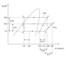
- FIG. 2 is a Mollier diagram of the refrigeration cycle of a refrigerator.
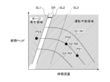
- 2 is a graph showing a performance curve of a compressor.
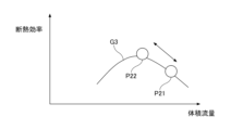
- 4 is a graph showing the relationship between the volumetric flow rate and the adiabatic efficiency in a compressor. 4 is a flowchart showing a control procedure in the refrigerator.
- the refrigerator 100 shown in Fig. 1 is used in, for example, an air conditioner, a refrigeration device, and a refrigeration device.
- the refrigerator 100 may also be used in other devices.
- the refrigerator 100 executes a refrigeration cycle.
- the refrigeration cycle of the refrigerator 100 is a vapor compression refrigeration cycle.
- the refrigerator 100 includes a compressor 10, a condenser 20, an expansion valve 30, and an evaporator 40.
- the refrigerant which is the working fluid of the refrigerator 100, is not particularly limited.
- the compressor 10 compresses the refrigerant gas.
- the condenser 20 condenses the refrigerant gas compressed by the compressor 10.
- the expansion valve 30 expands the refrigerant condensed by the condenser 20.
- the evaporator 40 evaporates the refrigerant expanded by the expansion valve 30.
- the refrigerant gas evaporated by the evaporator 40 is sucked into the compressor 10.
- the compressor 10 performs reversible adiabatic compression of the refrigerant gas.
- the refrigerant gas supplied to the condenser 20 releases heat at constant pressure and liquefies.
- the liquefied refrigerant expands irreversibly at constant enthalpy in the expansion valve 30, causing part of the refrigerant to evaporate.
- the refrigerant absorbs heat at constant pressure in the evaporator 40.
- the refrigerator 100 is equipped with pipes L11 to L14 through which the refrigerant flows.
- Pipe L11 is a suction pipe that connects the evaporator 40 and the compressor 10.
- Pipe L12 connects the compressor 10 and the condenser 20.
- Pipe L13 connects the condenser 20 and the expansion valve 30.
- Pipe L14 connects the expansion valve 30 and the evaporator 40.
- Refrigerant gas flows through pipe L11 and is sucked into compressor 10.
- Refrigerant gas compressed by compressor 10 flows through pipe L12 and is supplied to condenser 20.
- Refrigerant liquid liquefied in condenser 20 flows through pipe L13 and enters expansion valve 30.
- Refrigerant expanded in expansion valve 30 flows through pipe L14 and is supplied to evaporator 40.
- Refrigerant gas that has absorbed heat in evaporator 40 flows through pipe L11 and is supplied to compressor 10.
- the compressor 10 is, for example, a turbo compressor.
- the compressor 10 includes a casing 11, an impeller 12, a drive shaft 13, bearings 14, and a motor 50.
- the casing 11 houses the impeller 12, the drive shaft 13, the bearings 14, and the motor 50.
- the casing 11 has a compression chamber 11a that houses the impeller 12 and a motor chamber 11b that houses the motor 50.
- the impeller 12 is provided at one end of the drive shaft 13.
- the other end of the drive shaft 13 is disposed inside the motor chamber 12b.
- the drive shaft 13 includes the rotating shaft of the motor 50.
- the bearing 14 rotatably supports the drive shaft 13.
- the bearing 14 is fixed to the casing 11.
- the bearing 14 may be, for example, a radial bearing.
- the compressor 10 includes a plurality of bearings 14.
- the bearing 14 may be, for example, an oil-less bearing.
- the bearing 14 may be a sliding bearing or a rolling bearing.
- the motor 50 is the driving source of the compressor 10.
- the motor 50 has a rotor and a stator.
- the rotor is fixed to the drive shaft 13 and rotates together with the drive shaft 13.
- the stator is fixed to the casing 11 and is disposed around the rotor.
- the refrigerator 100 is equipped with an inverter 60.
- the inverter 60 controls the rotation speed of the motor 50.
- the inverter 60 is a controller that controls the operating frequency of the motor 50.
- the impeller 12 of the compressor 10 rotates by receiving a rotational driving force from the motor 50. As the impeller 12 rotates, the refrigerant gas is compressed.
- the compressor 10 is not limited to a turbo compressor (centrifugal compressor) and may be a positive displacement compressor.
- the positive displacement compressor may be, for example, a rotary type, a scroll type, a reciprocating type, or a screw type.
- the condenser 20 is a heat exchanger that cools the high-temperature, high-pressure refrigerant vapor compressed by the compressor 10.
- the condenser 20 condenses the refrigerant by exchanging heat between the refrigerant and, for example, water or air.
- the heat exchanger that is the condenser 20 may be, for example, a water-cooled type, an air-cooled type, an evaporative type, or another type.
- the heat exchanger may be a shell-and-tube type, a double-tube type, a plate-fin type, or another type.
- the expansion valve 30 throttles and expands the high-pressure refrigerant liquid coming out of the condenser 20.
- the refrigerant that passes through the expansion valve 30 is in a low-pressure, low-temperature state.
- the refrigerant that passes through the expansion valve 30 is in a partially evaporated state, and is in a wet vapor state in which saturated vapor and saturated liquid coexist.
- the evaporator 40 is a heat exchanger that exchanges heat between the refrigerant that has expanded after leaving the expansion valve 30 and the cooled fluid.
- the cooled fluid is the fluid that is to be cooled.
- the cooled fluid is, for example, air or water.
- the cooled fluid may be other fluids.
- the refrigerant in a wet vapor state absorbs heat from the cooled fluid and evaporates.
- the evaporator 40 may be, for example, an air heat exchanger. An air heat exchanger transfers heat between the refrigerant and air.
- the evaporator 40 may be, for example, a dry type, a flooded type, or a liquid forced circulation type.
- the evaporator 40 may be, for example, a plate fin coil type, or a shell and tube type.
- the refrigerator 100 includes the cooling mechanism 200 that cools a target component using the refrigerant discharged from the condenser 20.
- the target component is, for example, the motor 50.
- the target component may be the bearing 14 or the inverter 60 that is a controller for the motor 50.
- the target component may be other components.
- the cooling mechanism 200 may cool a plurality of target components.
- the cooling mechanism 200 may cool the motor 50, the bearing 14, and the inverter 60.
- the cooling mechanism 200 may cool the motor 50 housed in the casing 11, for example, by cooling the casing 11.
- the target component cooled by the cooling mechanism 200 may be the casing 11 of the compressor 10.
- the target component may be located at a position away from the compressor 10.
- the inverter 60 may be mounted on the compressor 10, or may be located at a position away from the compressor 10.
- the cooling mechanism 200 includes pipes L21 to L24, an expansion valve V21, and control valves V23 and V24.
- Pipe L21 connects the condenser 20 to the motor chamber 11b.
- Pipe L21 connects the motor chamber 11b to pipe L13, which is connected to the outlet of the condenser 20.
- Pipe L21 supplies the refrigerant that leaves the condenser 20 to the target component.
- An expansion valve V21 is provided in the pipe L21.
- the expansion valve V21 can adjust the flow rate and pressure of the refrigerant flowing through the pipe L21.
- the refrigerant that passes through the expansion valve V21 is decompressed and in a low-temperature state.
- the low-temperature refrigerant flows through the pipe L21 and is supplied to the target component.
- the pipe L21 is connected to, for example, the inside of the motor chamber 11b of the casing 11.
- the refrigerant that flows through the pipe L21 is supplied to the motor chamber 11b and cools the motor 50.
- Pipe L22 is connected to the motor chamber 11b. After cooling the motor 50, the refrigerant flows through pipe L22 and is discharged outside the motor chamber 11b.
- the outlet side of pipe L22 branches off and is connected to pipes L23 and L24.
- Pipe L23 connects pipe L22 and pipe L11.
- Pipe L24 connects pipe L22 and evaporator 40.
- Pipe L11 is an intake pipe, which is a first position.
- Evaporator 40 is an example of a second position different from the first position.
- the second position is a position included in refrigerator 100.
- the second position is not limited to evaporator 40, and may be another position.
- the second position may be the inlet of the subsequent compression mechanism (impeller).
- the first position may be the intake pipe to the subsequent compression mechanism. In refrigerator 100, there may be multiple first positions.
- Pipe L21 is an example of a first pipe that supplies the refrigerant discharged from the condenser 20 to the target part.
- Pipe L23 is an example of a second pipe that supplies the refrigerant that has cooled the target part to the suction pipe (pipe L11), which is a first position.
- Pipe L24 is an example of a third pipe that supplies the refrigerant that has cooled the target part to a second position different from the first position.
- a control valve V23 is provided in pipe L23, and a control valve V24 is provided in pipe L24.
- the control valve V23 is an example of a first control valve.
- the control valve V24 is an example of a second control valve.
- the opening and closing operations of the control valves V23 and V24 are controlled to select the supply destination of the refrigerant after cooling the motor 50.
- the first operating mode can be executed by opening the control valve V23 and closing the control valve V24.
- the refrigerant after cooling the motor 50 can be returned to the suction piping L11.
- the second operating mode can be executed by closing the control valve V23 and opening the control valve V24.
- the refrigerant after cooling the motor 50 can be returned to the evaporator 40.
- the connection destination of the pipe L24 may be the evaporator 40, or may be the pipe L14 connected to the evaporator 40.
- the refrigerant after cooling may be supplied directly to the evaporator 40, or may be supplied indirectly to the evaporator 40 via the pipe L14.
- the opening and closing operations of the control valves V23 and V24 may be controlled to return the cooled refrigerant only to the pipe L11, only to the evaporator 40, or to both the pipe L11 and the evaporator 40.
- the refrigerator 100 may also be provided with a three-way control valve instead of the control valves V23 and V24.
- the refrigerator 100 may also be provided with the control valve V23 in the pipe L23, and the control valve V24 not in the pipe L24.
- the refrigerator 100 may be provided with the control valve V24 in the pipe L24, and the control valve V23 not in the pipe L23.
- FIG. 5 is a graph showing a performance curve of a compressor.
- the horizontal axis shows the flow rate
- the vertical axis shows the adiabatic head.
- the horizontal axis shows the volumetric flow rate
- the vertical axis shows the adiabatic efficiency.
- performance curves G1 to G3 are shown.
- the performance curves G1 to G3 show the adiabatic head at different rotation speeds.
- surging may occur during operation.
- a centrifugal compressor if the pressure is increased while the flow rate is restricted during operation, rotating stall or surging will occur. Generally, as the flow rate decreases, rotating stall will occur, and eventually surging will occur.
- a backflow region will occur in the circumferential direction inside the centrifugal compressor (turbomachinery).
- the occurrence of such a backflow region is called rotating stall.
- the phenomenon in which a backflow region occurs is a localized phenomenon inside the compressor that fluctuates in the circumferential direction.
- the flow rate at which surging occurs is determined for each speed.
- the surge line (operating limit line) SL1 which is determined by the volumetric flow rate and the adiabatic head, is determined.
- the surge line SL1 the allowable operating limit line SL2, and the rotating stall occurrence line SL3 are shown.
- the allowable operating limit line SL2 is in the operating region where the refrigerant flow rate is large relative to the surge line.
- the allowable operating limit line SL2 is a line that takes into account the margin SR relative to the surge line SL1.
- the area to the left of the surge line SL1 is the area where surging occurs.
- the area to the right of the allowable operating limit line SL2 is the operable area.
- Fig. 2 is a block diagram showing the control unit 210 of the chiller 100.
- Fig. 2 shows a hardware configuration of the control unit 210.
- the control unit 210 is electrically connected to various sensors 220, the inverter 60, the expansion valve 30, the expansion valve V21, and the control valves V23 and V24.
- the various sensors 220 may be, for example, a temperature sensor (outside air temperature sensor) that measures the temperature outside the refrigerator 100 (outside air temperature), a temperature sensor that measures the temperature of the refrigerant, a pressure sensor that measures the pressure of the refrigerant, a flow rate sensor that measures the flow rate of the refrigerant, etc.
- the various sensors 220 may also be sensors that acquire other information.
- the various sensors 220 include, for example, a suction pressure sensor 221, a suction temperature sensor 222, a discharge pressure sensor 223, a discharge temperature sensor 224, and a water temperature sensor 225.
- the suction pressure sensor 221 detects the pressure of the refrigerant gas sucked into the compressor 10.
- the suction temperature sensor 222 detects the temperature of the refrigerant gas sucked into the compressor 10.
- the discharge pressure sensor 223 detects the pressure of the refrigerant gas discharged from the compressor 10.
- the discharge temperature sensor 224 detects the temperature of the refrigerant gas discharged from the compressor 10.
- the water temperature sensor 225 detects the temperature of the water flowing into the evaporator 40.
- the water temperature sensor 226 detects the temperature of the water flowing out from the evaporator 40.
- the control unit 210 inputs data detected by the various sensors 220.
- the control unit 210 can calculate various data using the data acquired by the various sensors 220.
- the control unit 210 can calculate the volumetric flow rate of the refrigerant gas sucked into the compressor 10 using the data acquired from the water temperature sensors 225, 226.
- the control unit 210 can calculate the volumetric flow rate of the refrigerant gas based on the amount of heat transfer in the evaporator 40.
- the control unit 210 can calculate the volumetric flow rate of the refrigerant gas based on the entropy in the evaporator 40. In cases other than a water heat exchanger, the volumetric flow rate of the refrigerant gas may be calculated using a flow meter that measures the refrigerant flow rate.
- the control unit 210 includes a CPU 211 and a memory unit 212.
- the CPU (Center Processing Unit) 211 is responsible for the overall processing of the refrigeration machine 100.
- the CPU 211 can control the rotation speed of the motor 50 via the inverter 60.
- the CPU 211 can control the opening and closing operation of the expansion valve 30.
- the CPU 211 can control the opening and closing operation of the expansion valve V21.
- the CPU 211 can control the opening and closing operation of the control valves V23 and V24.
- the storage unit 212 includes a ROM (Read Only Memory) 213 and a RAM (Random Access Memory) 214.
- the ROM 213 stores various programs for causing the CPU 211 to execute control processes, as well as various data necessary for the operation of the refrigerator 100.
- the RAM 214 temporarily stores data obtained from the sensor 220.
- Fig. 3 is a functional block diagram showing the control unit 210 of the refrigerator 100.
- functional blocks that realize the functions of the refrigerator 100 are configured by a combination of hardware and software control units.
- each function of the embodiment can be realized by one or more processing circuits.
- processing circuit in this specification includes a processor programmed to execute each function by software, such as a processor implemented by an electronic circuit, and devices such as an ASIC (Application Specific Integrated Circuit), DSP (digital signal processor), FPGA (field programmable gate array), and conventional circuit modules designed to execute each function described above.
- ASIC Application Specific Integrated Circuit
- DSP digital signal processor
- FPGA field programmable gate array
- the CPU 211 of the control unit 210 executes a program stored in a storage unit 212 such as a ROM 213 to realize the functions of the motor control unit 231, the expansion valve control unit 232, and the valve control unit 233 shown in FIG. 3. Note that external devices and sensors connected to the control unit 210 may execute some of these functions. Furthermore, the functions of the control unit 210 are not limited to these.
- the motor control unit 231 can control the rotation speed of the motor 50 via the inverter 60.
- the control unit 210 can control the rotation speed of the impeller 12 of the compressor 10 by controlling the rotation speed of the motor 50.
- the expansion valve control unit 232 can control the expansion valve 30 to control the pressure of the refrigerant after passing through the expansion valve 30.
- the valve control unit 233 can control the opening and closing operation of the expansion valve V21.
- the valve control unit 233 can control the opening and closing operation of the control valve V23.
- the valve control unit 233 can control the opening and closing operation of the control valve V24.
- the valve control unit 233 may control the opening and closing operation of the expansion valve V21 to adjust the pressure of the refrigerant supplied to the motor 50.
- the valve control unit 233 can switch the supply destination of the cooled refrigerant by controlling the opening and closing operations of the control valves V23 and V24.
- the first operation mode can be executed by supplying the cooled refrigerant to the pipe L11.
- the second operation mode can be executed by supplying the cooled refrigerant to the evaporator 40.
- the motor control unit 231, the expansion valve control unit 232, and the valve control unit 233 can be realized by software using the programs stored in the storage unit 212. All or part of the motor control unit 231, the expansion valve control unit 232, and the valve control unit 233 may be realized by hardware such as an integrated circuit (IC).
- IC integrated circuit
- FIG. 4 a Mollier diagram in the refrigeration cycle of the refrigerator 100 will be described.
- the horizontal axis indicates enthalpy h
- the vertical axis indicates pressure P.
- Diagram Ph1 is a Ph diagram in the first operation mode.
- Diagram Ph2 is a Ph diagram in the second operation mode.
- the state change "1 ⁇ 2" is a change caused by reversible adiabatic compression by the compressor 10, and is an isentropic change.
- the enthalpy change that occurs when an isentropic change occurs is called adiabatic head.
- the state change "2 ⁇ 3" is an isobaric change in the condenser 20, and the refrigerant is condensed and cooled.
- the state change "3 ⁇ 4" is a throttle expansion by the expansion valve 30, and is a geometric enthalpy change.
- the state change “4 ⁇ 1" is an isobaric change in the evaporator 40, and the refrigerant is evaporated and heated.
- Diagram Ph1 shows a case where the refrigerant after cooling the target components is returned to the pipe L11, which is the suction gas line, in the first operation mode.
- the degree of superheat of the refrigerant gas sucked into the compressor 10 is relatively high.
- the refrigerant after cooling flows from the pipe L23 into the pipe L11, so that the temperature of the compressed refrigerant gas discharged from the compressor 10 is higher than that in the second operation mode.
- the amount of boost ⁇ P1 by the compressor 10 is smaller than the amount of boost ⁇ P2 in the second operation mode.
- the rotation speed and volumetric flow rate in the compressor 10 are the same.
- the rotation speed and volumetric flow rate in the compressor 10 are the same.
- the amount of boost ⁇ P1 is the difference between pressure P21 and pressure P1.
- the amount of boost ⁇ P2 is the difference between pressure P22 and pressure P1.
- the pressure P21 after discharge of the compressor 10 in the first operation mode is lower than the pressure P22 after discharge of the compressor 10 in the second operation mode.
- the refrigerator 100 can continue to operate at a point where the insulation efficiency is high, without operating at an operating point where the insulation efficiency is low. This makes it possible to widen the operating range of the refrigerator 100 compared to the conventional case.
- the operating range can be expanded while suppressing the occurrence of surging in the refrigerator 100.
- FIG. 5 is a graph showing the performance curves of a compressor.
- the horizontal axis shows the volumetric flow rate, and the vertical axis shows the adiabatic efficiency.
- performance curves G1 and G2 are shown.
- the performance curves G1 and G2 show the adiabatic head at different rotational speeds.
- operating points P21 and P22 are shown.
- FIG. 5 shows a surge line SL1.
- the surge line SL1 indicates the line where surging occurs. When the volumetric flow rate falls below the surge line SL1, surging occurs and the flow of the refrigerant gas becomes unstable.
- Operating point P21 is an operating point with a higher volumetric flow rate and lower adiabatic head than operating point P22.
- Operating point P22 is an operating point with a lower volumetric flow rate and higher adiabatic head than operating point P21.
- Operating point P23 is an operating point with a lower volumetric flow rate and higher adiabatic head than operating points P21 and P22. The volumetric flow rate of operating point P23 is below the surge line SL.
- Operating point P23 is a virtual operating point in an inoperable region.
- FIG. 6 is a graph showing the relationship between the volumetric flow rate and the adiabatic efficiency in the compressor.
- the horizontal axis shows the volumetric flow rate
- the vertical axis shows the adiabatic efficiency.
- Graph G3 is shown in FIG. 6.
- the adiabatic efficiency at operating point P21 is lower than the adiabatic efficiency at operating point P22.
- the adiabatic efficiency at operating point P22 is higher than the adiabatic efficiency at operating point P21.
- the adiabatic efficiency at operating point P22 is close to the peak of the adiabatic efficiency of compressor 10.
- the operating mode can be switched, and the operating points P21, P22 can be changed.
- the risk of surging can be reduced by switching to the operating point P21 that is farther from the surge line SL1.
- the operating point P22 with higher insulation efficiency or the operating point P21 with lower insulation efficiency can be selected.
- Diagram Ph2 shows a case where the cooled refrigerant is returned to the evaporator 40, which corresponds to the second operation mode.
- the degree of superheat of the refrigerant gas drawn into the compressor 10 is relatively low.
- the degree of superheat of the refrigerant gas drawn into the compressor 10 is lower than the degree of superheat of the refrigerant gas drawn into the compressor 10 in the first operation mode.
- the boost amount ⁇ P2 by the compressor 10 is greater than the boost amount ⁇ P1 in the first operation mode. Therefore, in the second operation mode, the pressure can be boosted to the pressure P22 that could not be boosted due to the limit on the rotation speed of the drive shaft 13 in the compressor 10.
- the limit on the rotation speed in the compressor 10 may be due to, for example, the strength of the rotor including the impeller 12, the drive shaft 13, and the rotor of the motor 50.
- the limit on the rotation speed in the compressor 10 may be due to, for example, shaft resonance of the rotor.
- the limit on the rotation speed in the compressor 10 may be due to, for example, the strength of the bearing 14 supporting the drive shaft 13.
- the pressure of the refrigerant gas discharged from the compressor 10 can be made higher than in the conventional case at the same rotation speed and volumetric flow rate. This makes it possible to expand the operating range of the refrigerator 100 compared to the conventional case. The operating range can be expanded while suppressing the occurrence of surging in the refrigerator 100.
- the circulating volumetric flow rate of the refrigerant in the refrigerator 100 is low, and the operating range of the refrigerator 100 can be expanded to an area where operation is not possible due to entering an area where surging occurs.
- the refrigeration capacity of the evaporator 40 is lower than in the first operation mode, and the refrigeration capacity of the evaporator 40 can be adjusted at the same required temperature difference ⁇ T.
- the heating capacity is not affected, and the refrigerator can be operated while maintaining a high pressure.
- the adiabatic head ⁇ h1 produced by the compressor 10 in the first operating mode is the same as the adiabatic head ⁇ h2 produced by the compressor 10 in the second operating mode.
- the slope of the isentropic line in the first operation mode is different from the slope of the isentropic line in the second operation mode.
- the slope of the isentropic line in the second operation mode is larger than the slope of the isentropic line in the first operation mode.
- the pressure P22 of the refrigerant gas compressed by the compressor 10 is higher than the pressure P21 of the refrigerant gas compressed by the compressor in the first operation mode.
- the slope of the isentropic line (1 ⁇ 2) becomes smaller. That is, in the case of the compressor 10, when the rotation speed and volumetric flow rate are the same, the adiabatic heads ⁇ h1 and ⁇ h2 are the same, but the pressure rise amounts ⁇ P1 and ⁇ P2 are different.
- the reached pressure P22 in the second operating mode is higher than the reached pressure P21 in the first operating mode. In other words, when the degree of suction superheat is high, the reached pressure P21 of the refrigerant after compression by the compressor 10 is lower (P21 ⁇ P22) compared to when the degree of suction superheat is low.
- Fig. 7 is a flow chart showing a control procedure in the refrigerator 100.
- the control unit 210 of the refrigerator 100 inputs various data.
- the control unit 210 inputs various data from various sensors 220.
- the control unit 210 can receive various signals from other input units and switches.
- the control unit 210 may input various data from external processing devices and terminals.
- the control unit 210 can input, for example, data related to the outside air temperature, data related to the heat load, and data related to the target water temperature (room temperature).
- the control unit 210 may calculate various data from the input data.
- the control unit 210 determines whether or not an end signal has been received (step S12). For example, when a user wishes to end the operation of the refrigerator 100, the user operates a switch. The switch outputs an end signal. When the control unit 210 receives an end signal (step S12; YES), the control unit 210 ends the process here. When the control unit 210 does not receive an end signal (step S12; NO), the control unit 210 executes the process of step S12.
- control unit 210 checks the operating point information of the compressor 10 after the next control (step S13).
- control unit 210 calculates the adiabatic head and volumetric flow rate of the operating point (step S14).
- the control unit 210 can calculate the adiabatic head and volumetric flow rate of the operating point using the various input data.
- the control unit 210 can calculate the future operating point after a predetermined time has passed using the calculated adiabatic head and volumetric flow rate.
- the control unit 210 may calculate the future operating point using, for example, the map shown in FIG. 5.
- control unit 210 determines whether the future operating point will exceed the operation allowable limit line SL2 (step S15). For example, the control unit 210 refers to the map shown in FIG. 5 and determines whether the future operating point is in the area to the left of the operation allowable limit line SL2. If the control unit 210 predicts that the future operating point will be in the area to the left of the operation allowable limit line SL2, it determines that the future operating point will exceed the operation allowable limit line SL2. If the volumetric flow rate is lower than the state indicated by the operation allowable limit line SL2, the operating point is to the left of the operation allowable limit line SL2. If the volumetric flow rate is higher than the state indicated by the operation allowable limit line SL2, the operating point is to the right of the operation allowable limit line SL2.
- step S15; YES If the future operating point exceeds the operating allowable limit line SL2 (step S15; YES), the control unit 210 executes the process of step S18. If the future operating point does not exceed the operating allowable limit line SL2 (step S15; NO), the control unit 210 executes the process of step S16.
- control unit 210 executes control.
- Control here includes, for example, control of the rotation speed of the compressor 10 and drive control of the valves.
- Valves here include, for example, the expansion valve 30, the expansion valve V21, the control valve V23, and the control valve V24.
- the control unit 210 may execute other controls.
- the control unit 210 executes various controls and operates the refrigerator 100.
- the control unit 210 checks the operating point information of the refrigerator 100 after the current control (step S17).
- the control unit 210 acquires various data and checks the operating point information of the refrigerator 100 after the current control.
- the control unit 210 checks, for example, the suction pressure and suction temperature of the refrigerant gas sucked into the compressor 10, the discharge pressure and discharge temperature of the refrigerant gas discharged from the compressor 10, and the volumetric flow rate of the refrigerant gas sucked into the compressor 10.
- step S17 the control unit 210 repeats steps S13 to S15.
- step S18 the control unit 210 determines whether the intake gas return destination can be switched to the evaporator 40.
- the intake gas return destination is the return destination of the refrigerant flowing through the pipe L22 shown in FIG. 1.
- the intake gas return destination is, for example, the evaporator 40 or the pipe L11.
- step S18 If the current intake gas return destination is pipe L11 (step S18; YES), the control unit 210 determines that the intake gas return destination can be switched to the evaporator 40, and executes the process of step S19.
- step S18 If the current return destination of the intake gas is the evaporator 40 (step S18; NO), the control unit 210 does not determine that the return destination of the intake gas can be switched to the evaporator 40 and executes step S20.
- step S19 the return destination of the intake gas is switched from pipe L11 to the evaporator 40.
- the refrigerant flowing through pipe L22 is supplied to the evaporator 40.
- the control unit 210 repeats the processes of steps S17, S13, S14, and S15.
- step S20 the control unit 210 transmits an error signal and ends the process. After executing the process of step S20, the control unit 210 may execute a process to stop the operation of the refrigerator 100.
- the refrigeration machine 100 includes a pipe L23 that supplies the refrigerant that has cooled the target component, the motor 50, to a pipe (the suction pipe at the first position) L11, and a pipe L24 that supplies the refrigerant that has cooled the motor 50 to an evaporator (at the second position) 40.
- the refrigerant after cooling the target parts can be supplied to the pipe L11, which is the first position, or to the evaporator 40, which is the second position.
- the refrigerator 100 can supply the refrigerant after cooling the target parts to both the pipe L11 and the evaporator 40.
- the refrigerator 100 by selecting the supply destination of the refrigerant after cooling the target parts, the operating state can be changed and the occurrence of surging can be suppressed. Since the refrigerator 100 can select the supply destination of the refrigerant after cooling the target parts, the operating range can be expanded.
- the refrigerator 100 even if the rotation speed of the compressor 10 is not changed, the refrigeration capacity of the evaporator 40 can be adjusted by changing the supply destination of the cooled refrigerant. Furthermore, with the refrigerator 100, the operable range can be expanded by changing the supply destination of the cooled refrigerant, and it can be operated even in a pressure range where operation was not possible due to the occurrence of surging. With the refrigerator 100, the occurrence of surging can be suppressed by changing the operating state by selecting the supply destination of the refrigerant after cooling the target components.
- the target component is the motor 50.
- the refrigerator 100 of this embodiment by cooling the motor 50, heat generation in the motor 50 can be suppressed, and the reliability of the motor 50 can be improved.
- the refrigerator 100 of this embodiment by cooling the motor 50, the constraints on the temperature of the motor 50 can be alleviated.
- the constraints on the temperature of the motor 50 include the temperature conditions of the windings or magnets of the motor 50. In the refrigerator 100, since the windings and magnets of the motor 50 can be cooled, the range in which the compressor 10 can be operated can be expanded.
- the target part is not limited to the motor 50.
- the target part may be the bearing 14 that supports the drive shaft (rotating shaft) 13 of the compressor 10.
- the bearing 14 can be cooled to prevent the bearing 14 from burning out.
- the restrictions on the temperature of the bearing 14 can be alleviated.
- the bearing 14 can be cooled to prevent the temperature rise of the bearing 14, and the restrictions on the bearing 14 can be alleviated. Therefore, the range in which the compressor 10 can be operated can be expanded.
- the target component may be the inverter 60, which is the controller for the motor 50.
- the target component may be the inverter 60, which is the controller for the motor 50.
- the inverter 60 by cooling the inverter 60, the occurrence of malfunctions in the inverter 60 can be suppressed, and the reliability of the inverter 60 can be improved.
- the second position is the evaporator 40.
- the degree of superheat of the refrigerant gas supplied to the compressor 10 can be relatively low by returning the refrigerant after cooling the target component to the evaporator 40.
- the refrigeration capacity is reduced.
- this second operating mode it is necessary to increase the suction volume flow rate required to ensure the refrigeration capacity. Therefore, at an operating point where the required refrigeration capacity is large, a rotation speed constraint on the compressor 10 occurs. In order to avoid such a rotation speed constraint on the compressor 10, by switching from the second operating mode to the first operating mode, it is possible to ensure the refrigeration capacity while maintaining the rotation speed of the compressor 10.
- the target component is the motor 50
- the pipe L21 is connected to a flow path that communicates with the inside of the motor chamber 11b.
- the pipe L21 may include a flow path that communicates with the inside of the motor chamber 11b.
- the flow path that communicates with the motor chamber 11b includes a flow path that penetrates the casing 11.
- a refrigerant can be supplied to the inside of the motor chamber 11b, and the rotating shaft, rotor, and stator of the motor 50 inside the casing 11 can be directly cooled.
- the constraints on the temperature of the motor 50 can be relaxed, and therefore the range in which the compressor 10 can be operated can be expanded.
- the target part may be the bearing 14 that supports the drive shaft 13 of the compressor 10, and the bearing 14 may be an oil-less bearing.
- a refrigerant can be used as the gas supplied to the oil-less bearing.
- an oil-less bearing it is possible to improve the wear resistance and seizure resistance of the bearing 14.
- an oil-less bearing it is possible to reduce the maintenance required for the bearing 14.
- the oil-less bearing is cooled, so that the restrictions on the temperature of the bearing 14 can be alleviated.
- the refrigerator 100 of this embodiment by adopting an oil-less bearing, it is not necessary to use a bearing that uses a highly viscous fluid such as oil as the working fluid.
- an oil-less bearing is used, bearing loss can be reduced even at high speed rotation. Therefore, the restrictions on the rotation speed of the bearing 14 can be alleviated, and the range in which the compressor 10 can be operated can be expanded.
- the evaporator 40 is an air heat exchanger that transfers heat between the refrigerant and the air.
- the air can be cooled by exchanging heat between the refrigerant and the air.
- the refrigerator 100 can be applied to an air conditioning system, and can adjust the temperature of the air inside a house, for example.
- the air heat exchanger is affected by the outside air temperature, and therefore experiences greater temperature changes than the water heat exchanger.
- the operating state of the compressor 10 downstream of the air heat exchanger is more susceptible to change, and a chiller 100 with air heat exchanger requires a wider operating range than a chiller with a water heat exchanger.
- the chiller 100 of this embodiment can expand the operable range, making it effective for chillers with air heat exchangers whose operating state is more susceptible to change.
- the refrigerator 100 includes a control valve V23 provided in the pipe L23, a control valve V24 provided in the pipe L24, and a controller 210 that controls the control valves V23 and V24.
- the controller 210 controls the opening and closing operations of the control valves V23 and V24, thereby switching the supply destination of the refrigerant after cooling the target component.
- control unit 210 can execute a first operating mode by opening the control valve V23 and closing the control valve V24, and can execute a second operating mode by closing the control valve V23 and opening the control valve V24.
- the refrigerant after cooling the target parts can be returned to the pipe L11, which is the intake pipe of the compressor 10. This allows the degree of superheat of the refrigerant gas supplied to the compressor 10 to be relatively high.
- the refrigerant after cooling the target parts can be supplied to the evaporator 40, which is the second location.
- the degree of superheat of the refrigerant gas supplied to the compressor 10 can be changed, and the occurrence of surging can be suppressed.
- the adjustment range of operation can be expanded.
- the compressor 10 In the first operating mode, in which the refrigerant after cooling the target components is returned to the piping L11, which is the intake piping of the compressor 10, the compression power required by the compressor 10 increases due to an increase in the degree of superheat of the refrigerant. Therefore, at an operating point where the required power is large, restrictions on the motor output arise. In order to avoid such restrictions on the motor output, the compressor 10 can continue to operate by switching from the first operating mode to the second operating mode. As a result, the operable range can be expanded.
- the compressor 10 of this embodiment by switching from the second operating mode to the first operating mode, it is possible to avoid restrictions on the rotation speed of the compressor 10, and it is possible to ensure refrigeration capacity while maintaining the rotation speed of the compressor 10.
- the refrigerator 100 it is possible to switch from the first operating mode to the second operating mode, or from the second operating mode to the first operating mode, depending on the operating state, so that it is possible to expand the operable range.
- the refrigerator 100 may include a control unit 210 that controls the flow rate of the refrigerant flowing through the third pipe L24 based on a surge line SL1 that indicates the boundary of the area where surging occurs in the compressor 10.
- the occurrence of surging in the compressor 10 can be suppressed by controlling the flow rate of the refrigerant flowing through the pipe L24 based on the surge line SL1.
- the control unit 210 controls the flow rate of the refrigerant flowing through the pipe L24 based on the allowable operating limit line SL2, which is an operating region on the side where the refrigerant flow rate is large relative to the surge line SL1 and takes into account the margin SR relative to the surge line SL1.
- the occurrence of surging in the compressor 10 can be reliably suppressed by controlling the flow rate of the refrigerant flowing through the pipe L24 based on the allowable operating limit line SL2, which takes into account the margin SR relative to the surge line SL1.
- the second location is the evaporator
- the control unit 210 predicts the operating point of the compressor 10 at a second point in time that is a predetermined time after the current first point in time, and can increase the flow rate of the refrigerant flowing through the pipe L24 if the predicted operating point is in a region closer to the surge line SL1 than the operational limit line SL2, or in a region where surging occurs.
- the operating point of the compressor 10 at a second point in time that is later than the present can be predicted to predict the occurrence of surging.
- the flow rate of the refrigerant flowing through the pipe L24 can be increased to suppress the occurrence of surging.
- the refrigerant gas can be switched from being returned to the pipe L11, which is the suction side of the compressor 10, to being returned to the evaporator 40.
- the amount of pressure increase by the compressor 10 can be increased even with the same rotation speed and volumetric flow rate.
- the slope of the isentropic line becomes steeper due to a decrease in the degree of superheat, and the ultimate pressure can be increased even with the same insulating head.
- the refrigeration capacity is reduced by switching the return destination of the refrigerant gas to the evaporator 40.
- the refrigeration capacity is reduced because there is a portion of the enthalpy change inside the evaporator 40 that cannot be used as refrigeration capacity. Therefore, in the refrigerator 100, the refrigeration capacity can be reduced without reducing the flow rate of the compressor 10.
- the compressor 10 may be a single-stage compressor or a multi-stage compressor equipped with multiple impellers 12.
- the cooled refrigerant may be supplied to the subsequent impeller (compression mechanism).
- the cooled refrigerant is supplied to the evaporator 40, which is the second position, but the refrigerant may be supplied to any position of the evaporator 40, and the cooled refrigerant may be supplied to the upstream pipe L14 connected to the evaporator 40.
- the second position may also be multiple locations.
- the cooled refrigerant may be supplied to multiple locations of the evaporator 40.
- One aspect of the present invention may be as follows:
- a refrigerator that performs a refrigeration cycle
- a compressor that compresses a refrigerant; a condenser for condensing the compressed refrigerant; an expansion valve for expanding the condensed refrigerant; an evaporator for evaporating the expanded refrigerant; a suction pipe connecting the evaporator and the compressor;
- a motor that drives the compressor; a first pipe that supplies the refrigerant discharged from the condenser to a target component; a second pipe that supplies the refrigerant that has cooled the target component to the suction pipe that is at the first position; a third pipe that supplies the refrigerant that has cooled the target component to a second position that is different from the first position and is included in the refrigerator.
- ⁇ 2> The refrigerator according to ⁇ 1> above, wherein the compressor is a turbo compressor.
- the target part is the motor, or a bearing supporting a rotating shaft of the compressor, or a controller of the motor.
- ⁇ 4> The refrigeration machine according to any one of ⁇ 1> to ⁇ 3> above, wherein the second location is the evaporator.
- the target component is the motor, The refrigerator according to any one of ⁇ 1> to ⁇ 4> above, wherein the first pipe is connected to a flow path communicating with an inside of a casing of the motor.
- the target component is a bearing that supports a rotating shaft of the compressor
- the refrigerator according to any one of ⁇ 1> to ⁇ 5> above, wherein the bearing is an oil-less bearing.
- the evaporator is an air heat exchanger that transfers heat between the refrigerant and air.
- ⁇ 8> a first control valve provided in the second pipe; a second control valve provided in the third pipe; and a control unit that controls the first control valve and the second control valve.
- the control unit is A first operation mode can be executed by opening the first control valve and closing the second control valve,
- the refrigeration machine according to any one of ⁇ 1> to ⁇ 9>, further comprising a control unit that controls a flow rate of the refrigerant flowing through the third piping, based on a surge line indicating a boundary of a region where surging occurs in the compressor.
- control unit controls the flow rate of the refrigerant flowing through the third piping based on an allowable operation limit line which is an operation region on a side where a flow rate of the refrigerant is large with respect to the surge line and which takes into consideration a margin with respect to the surge line.
- the second location is the evaporator;
- the control unit is predicting an operating point of the compressor at a second point in time that is a predetermined time after the current first point in time;
- Refrigeration unit 10 Compressor 13 Drive shaft (rotating shaft) 14 Bearings (target parts, oil-less bearings) 20 Condenser 30 Expansion valve 40 Evaporator (second position, air heat exchanger) 50 Motor (target part) 60 Inverter (motor controller) 210 Control unit L11 Pipe (suction pipe, first position) L21 Pipe (first pipe) L23 piping (second piping) L24 piping (third piping) V23 Control valve (first control valve) V24 Control valve (second control valve)
Landscapes
- Engineering & Computer Science (AREA)
- Physics & Mathematics (AREA)
- Mechanical Engineering (AREA)
- Thermal Sciences (AREA)
- General Engineering & Computer Science (AREA)
- Control Of Positive-Displacement Air Blowers (AREA)
Abstract
Description
図1に示される冷凍機100は、例えば、空気調和装置、冷凍機器、及び冷蔵機器に利用される。冷凍機100は、その他の機器に利用されてもよい。冷凍機100は冷凍サイクルを実行する。冷凍機100の冷凍サイクルは、蒸気圧縮式冷凍サイクルである。冷凍機100は、圧縮機10、凝縮器20、膨張弁30、及び蒸発器40を備える。
次に、冷却機構200について説明する。冷凍機100は、凝縮器20から排出された冷媒を用いて対象部品を冷却する冷却機構200を備える。対象部品は、例えばモータ50である。対象部品は、軸受14でもよく、モータ50のコントローラであるインバータ60でもよい。対象部品は、その他の部品でもよい。冷却機構200は、複数の対象部品を冷却してもよい。冷却機構200は、モータ50、軸受14、及びインバータ60を冷却してもよい。冷却機構200は、例えば、ケーシング11を冷却することにより、ケーシング11に収容されたモータ50を冷却してもよい。冷却機構200によって冷却される対象部品は、圧縮機10のケーシング11でもよい。
次にサージングについて説明する。図5は、圧縮機の性能曲線を示すグラフである。図5では、横軸に流量を示し、縦軸に断熱ヘッドを示す。図6では、横軸に体積流量を示し、縦軸に断熱効率を示す。図5では、性能曲線G1~G3が図示されている。性能曲線G1~G3は、異なる回転数における断熱ヘッドを示す。
従来技術の課題について説明する。例えば従来技術に係る空調機では、低流量(冷凍能力の低下)かつ、高ヘッド(高圧力差)に変化した場合に、遠心圧縮機の動作点がサージラインSL1を超えた領域となり、遠心圧縮機の運転ができなくなる。
次に図2を参照して、冷凍機100の制御部210について説明する。図2は、冷凍機100の制御部210を示すブロック図である。図2は、制御部210のハードウェア構成を示す。図2に示されるように、制御部210は、各種センサ220、インバータ60、膨張弁30、膨張弁V21、及び制御弁V23,V24と電気的に接続されている。
次に図3を参照して、制御部210における機能ブロックについて説明する。図3は、冷凍機100の制御部210を示す機能ブロック図である。制御部210では、ハードウェアとソフトウェア制御部との組み合わせによって、冷凍機100の機能を実現する機能ブロックが構成される。
次に図4を参照して、冷凍機100の冷凍サイクルにおけるモリエル線図について説明する。図4では、横軸にエンタルピhを示し、縦軸に圧力Pを示す。線図Ph1は、第1運転モードにおけるPh線図である。線図Ph2は、第2運転モードにおけるPh線図である。
線図Ph1は、対象部品を冷却した後の冷媒を吸入ガスラインである配管L11に戻した場合であり、第1運転モードの場合である。第1運転モードでは、圧縮機10に吸入する冷媒ガスの過熱度が相対的に高くなる。配管L23から冷却後の冷媒が配管L11に流入することにより、圧縮機10から吐出される圧縮後の冷媒ガスの温度は、第2運転モードと比較して高くなる。
線図Ph2は、冷却後の冷媒を蒸発器40に戻した場合であり、第2運転モードの場合である。第2運転モードでは、圧縮機10に吸入する冷媒ガスの過熱度が相対的に低くなる。第2運転モードにおいて圧縮機10に吸入する冷媒ガスの過熱度は、第1運転モードにおいて圧縮機10に吸入する冷媒ガスの過熱度よりも低い。
第1運転モードにおける圧縮機10による断熱ヘッドΔh1は、第2運転モードにおける圧縮機10による断熱ヘッドΔh2と同じである。
次に図7を参照して冷凍機100における制御の手順について説明する。図7は、冷凍機100における制御の手順を示すフローチャートである。
本実施形態に係る冷凍機100は、対象部品であるモータ50を冷却した冷媒を配管(第1位置である吸入配管)L11に供給する配管L23と、モータ50を冷却した冷媒を蒸発器(第2位置)40に供給する配管L24とを備える。
冷凍サイクルを実行する冷凍機であって、
冷媒を圧縮する圧縮機と、
圧縮された前記冷媒を凝縮する凝縮器と、
凝縮された前記冷媒を膨張させる膨張弁と、
膨張した前記冷媒を蒸発させる蒸発器と、
前記蒸発器と前記圧縮機とを接続する吸入配管と、
前記圧縮機を駆動するモータと、
前記凝縮器から吐出された前記冷媒を対象部品に供給する第1配管と、
前記対象部品を冷却した前記冷媒を第1位置である前記吸入配管に供給する第2配管と、
前記対象部品を冷却した前記冷媒を前記第1位置とは異なる位置であり当該冷凍機に含まれる第2位置に供給する第3配管と、を備える冷凍機。
<2>
前記圧縮機は、ターボ圧縮機である、上記<1>に記載の冷凍機。
<3>
前記対象部品は、前記モータ、又は、前記圧縮機の回転軸を支持する軸受、又は、前記モータのコントローラである、上記<1>又は<2>に記載の冷凍機。
<4>
前記第2位置は、前記蒸発器である、上記<1>~<3>の何れか一つに記載の冷凍機。
<5>
前記対象部品は、前記モータであり、
前記第1配管は、前記モータのケーシング内に連通する流路に接続されている、上記<1>~<4>の何れか一つに記載の冷凍機。
<6>
前記対象部品は、前記圧縮機の回転軸を支持する軸受であり、
前記軸受は、オイルレス軸受である、上記<1>~<5>の何れか一つに記載の冷凍機。
<7>
前記蒸発器は前記冷媒と空気との間で伝熱する空気熱交換器である、上記<1>~<6>の何れか一つに記載の冷凍機。
<8>
前記第2配管に設けられた第1制御弁と、
前記第3配管に設けられた第2制御弁と、
前記第1制御弁及び前記第2制御弁を制御する制御部と、を備える上記<1>~<7>の何れか一つに記載の冷凍機。
<9>
前記制御部は、
前記第1制御弁を開状態とし、前記第2制御弁を閉状態として、第1運転モードを実行可能であり、
前記第1制御弁を閉状態とし、前記第2制御弁を開状態として、第2運転モードを実行可能である、上記<8>に記載の冷凍機。
<10>
前記圧縮機においてサージングが発生する領域の境界を示すサージラインに基づいて、前記第3配管を流れる前記冷媒の流量を制御する制御部を備える上記<1>~<9>の何れか一つに記載の冷凍機。
<11>
前記制御部は、前記サージラインに関して前記冷媒の流量が大きい側の運転領域であり、前記サージラインに対して余裕代が考慮された運転許容限界ラインに基づいて、前記第3配管を流れる前記冷媒の流量を制御する上記<10>に記載の冷凍機。
<12>
前記第2位置は、前記蒸発器であり、
前記制御部は、
現在の第1時点よりも所定時間が経過した第2時点における前記圧縮機の動作点を予測し、
予測した前記動作点が前記運転許容限界ラインよりも前記サージラインに近い領域、又は、前記サージングが発生する領域内に存在する場合に、前記第3配管を流れる前記冷媒の流量を増加させる上記<11>に記載の冷凍機。
10 圧縮機
13 駆動軸(回転軸)
14 軸受(対象部品、オイルレス軸受)
20 凝縮器
30 膨張弁
40 蒸発器(第2位置、空気熱交換器)
50 モータ(対象部品)
60 インバータ(モータのコントローラ)
210 制御部
L11 配管(吸入配管、第1位置)
L21 配管(第1配管)
L23 配管(第2配管)
L24 配管(第3配管)
V23 制御弁(第1制御弁)
V24 制御弁(第2制御弁)
Claims (12)
- 冷凍サイクルを実行する冷凍機であって、
冷媒を圧縮する圧縮機と、
圧縮された前記冷媒を凝縮する凝縮器と、
凝縮された前記冷媒を膨張させる膨張弁と、
膨張した前記冷媒を蒸発させる蒸発器と、
前記蒸発器と前記圧縮機とを接続する吸入配管と、
前記圧縮機を駆動するモータと、
前記凝縮器から吐出された前記冷媒を対象部品に供給する第1配管と、
前記対象部品を冷却した前記冷媒を第1位置である前記吸入配管に供給する第2配管と、
前記対象部品を冷却した前記冷媒を前記第1位置とは異なる位置であり当該冷凍機に含まれる第2位置に供給する第3配管と、を備える冷凍機。 - 前記圧縮機は、ターボ圧縮機である、請求項1に記載の冷凍機。
- 前記対象部品は、前記モータ、又は、前記圧縮機の回転軸を支持する軸受、又は、前記モータのコントローラである、請求項1又は2に記載の冷凍機。
- 前記第2位置は、前記蒸発器である、請求項1~3の何れか一項に記載の冷凍機。
- 前記対象部品は、前記モータであり、
前記第1配管は、前記モータのケーシング内に連通する流路に接続されている、請求項1~4の何れか一項に記載の冷凍機。 - 前記対象部品は、前記圧縮機の回転軸を支持する軸受であり、
前記軸受は、オイルレス軸受である、請求項1~5の何れか一項に記載の冷凍機。 - 前記蒸発器は前記冷媒と空気との間で伝熱する空気熱交換器である、請求項1~6の何れか一項に記載の冷凍機。
- 前記第2配管に設けられた第1制御弁と、
前記第3配管に設けられた第2制御弁と、
前記第1制御弁及び前記第2制御弁を制御する制御部と、を備える請求項1~7の何れか一項に記載の冷凍機。 - 前記制御部は、
前記第1制御弁を開状態とし、前記第2制御弁を閉状態として、第1運転モードを実行可能であり、
前記第1制御弁を閉状態とし、前記第2制御弁を開状態として、第2運転モードを実行可能である、請求項8に記載の冷凍機。 - 前記圧縮機においてサージングが発生する領域の境界を示すサージラインに基づいて、前記第3配管を流れる前記冷媒の流量を制御する制御部を備える請求項1~9の何れか一項に記載の冷凍機。
- 前記制御部は、前記サージラインに関して前記冷媒の流量が大きい側の運転領域であり、前記サージラインに対して余裕代が考慮された運転許容限界ラインに基づいて、前記第3配管を流れる前記冷媒の流量を制御する請求項10に記載の冷凍機。
- 前記第2位置は、前記蒸発器であり、
前記制御部は、
現在の第1時点よりも所定時間が経過した第2時点における前記圧縮機の動作点を予測し、
予測した前記動作点が前記運転許容限界ラインよりも前記サージラインに近い領域、又は、前記サージングが発生する領域内に存在する場合に、前記第3配管を流れる前記冷媒の流量を増加させる請求項11に記載の冷凍機。
Priority Applications (2)
| Application Number | Priority Date | Filing Date | Title |
|---|---|---|---|
| CN202480017403.9A CN120858261A (zh) | 2023-03-31 | 2024-03-29 | 制冷机 |
| EP24780851.2A EP4542132A4 (en) | 2023-03-31 | 2024-03-29 | Refrigerator |
Applications Claiming Priority (2)
| Application Number | Priority Date | Filing Date | Title |
|---|---|---|---|
| JP2023058725 | 2023-03-31 | ||
| JP2023-058725 | 2023-03-31 |
Publications (1)
| Publication Number | Publication Date |
|---|---|
| WO2024204756A1 true WO2024204756A1 (ja) | 2024-10-03 |
Family
ID=92905951
Family Applications (1)
| Application Number | Title | Priority Date | Filing Date |
|---|---|---|---|
| PCT/JP2024/013147 Ceased WO2024204756A1 (ja) | 2023-03-31 | 2024-03-29 | 冷凍機 |
Country Status (4)
| Country | Link |
|---|---|
| EP (1) | EP4542132A4 (ja) |
| JP (1) | JP7590683B2 (ja) |
| CN (1) | CN120858261A (ja) |
| WO (1) | WO2024204756A1 (ja) |
Citations (8)
| Publication number | Priority date | Publication date | Assignee | Title |
|---|---|---|---|---|
| JPS4943104A (ja) * | 1972-07-03 | 1974-04-23 | ||
| JPH0113697Y2 (ja) | 1984-02-29 | 1989-04-21 | ||
| JPH0319499U (ja) * | 1989-07-07 | 1991-02-26 | ||
| JP2006194579A (ja) * | 2005-01-10 | 2006-07-27 | Samsung Electronics Co Ltd | ターボ圧縮機を具備した冷凍装置 |
| US20150226467A1 (en) * | 2012-11-28 | 2015-08-13 | Johnson Controls Technology Company | Motor cooling method for a compressor |
| JP2021156220A (ja) * | 2020-03-27 | 2021-10-07 | 三菱重工サーマルシステムズ株式会社 | ターボ圧縮機およびこれを備えたターボ冷凍機 |
| JP2023013514A (ja) * | 2021-07-16 | 2023-01-26 | ダイキン工業株式会社 | ターボ圧縮機および冷凍装置 |
| JP2023058725A (ja) | 2017-06-28 | 2023-04-25 | ジーイー-ヒタチ・ニュークリア・エナジー・アメリカズ・エルエルシー | 非常に単純化された沸騰水反応器のための非常用復水器 |
Family Cites Families (6)
| Publication number | Priority date | Publication date | Assignee | Title |
|---|---|---|---|---|
| JP3716061B2 (ja) * | 1996-10-25 | 2005-11-16 | 三菱重工業株式会社 | ターボ冷凍機 |
| WO2015053939A1 (en) * | 2013-10-09 | 2015-04-16 | Johnson Controls Technology Company | Motor housing temperature control system |
| CN204227741U (zh) * | 2014-10-31 | 2015-03-25 | 烟台荏原空调设备有限公司 | 一种螺杆式制冷系统 |
| CN112212531B (zh) * | 2020-08-31 | 2023-06-16 | 青岛海尔空调电子有限公司 | 压缩机冷却系统及冷却方法 |
| CN112856859A (zh) * | 2021-03-24 | 2021-05-28 | 无锡职业技术学院 | 一种制冷剂液体润滑的滚动轴承系统及其润滑方法 |
| KR102577092B1 (ko) * | 2021-06-09 | 2023-09-11 | 엘지전자 주식회사 | 터보 압축기 |
-
2024
- 2024-03-29 WO PCT/JP2024/013147 patent/WO2024204756A1/ja not_active Ceased
- 2024-03-29 EP EP24780851.2A patent/EP4542132A4/en active Pending
- 2024-03-29 CN CN202480017403.9A patent/CN120858261A/zh active Pending
- 2024-03-29 JP JP2024055205A patent/JP7590683B2/ja active Active
Patent Citations (8)
| Publication number | Priority date | Publication date | Assignee | Title |
|---|---|---|---|---|
| JPS4943104A (ja) * | 1972-07-03 | 1974-04-23 | ||
| JPH0113697Y2 (ja) | 1984-02-29 | 1989-04-21 | ||
| JPH0319499U (ja) * | 1989-07-07 | 1991-02-26 | ||
| JP2006194579A (ja) * | 2005-01-10 | 2006-07-27 | Samsung Electronics Co Ltd | ターボ圧縮機を具備した冷凍装置 |
| US20150226467A1 (en) * | 2012-11-28 | 2015-08-13 | Johnson Controls Technology Company | Motor cooling method for a compressor |
| JP2023058725A (ja) | 2017-06-28 | 2023-04-25 | ジーイー-ヒタチ・ニュークリア・エナジー・アメリカズ・エルエルシー | 非常に単純化された沸騰水反応器のための非常用復水器 |
| JP2021156220A (ja) * | 2020-03-27 | 2021-10-07 | 三菱重工サーマルシステムズ株式会社 | ターボ圧縮機およびこれを備えたターボ冷凍機 |
| JP2023013514A (ja) * | 2021-07-16 | 2023-01-26 | ダイキン工業株式会社 | ターボ圧縮機および冷凍装置 |
Non-Patent Citations (1)
| Title |
|---|
| See also references of EP4542132A4 |
Also Published As
| Publication number | Publication date |
|---|---|
| JP2024146895A (ja) | 2024-10-15 |
| EP4542132A1 (en) | 2025-04-23 |
| CN120858261A (zh) | 2025-10-28 |
| JP7590683B2 (ja) | 2024-11-27 |
| EP4542132A4 (en) | 2025-11-19 |
Similar Documents
| Publication | Publication Date | Title |
|---|---|---|
| JP5349686B2 (ja) | 冷凍サイクル装置 | |
| JP4999529B2 (ja) | 熱源機および冷凍空調装置 | |
| US9389005B2 (en) | Two-stage compression refrigeration cycle device | |
| CN104755855B (zh) | 冷冻循环装置 | |
| JP4895883B2 (ja) | 空気調和装置 | |
| CN101438109A (zh) | 可变容量多回路空调系统 | |
| US9222706B2 (en) | Refrigeration cycle apparatus and operating method of same | |
| JP7189423B2 (ja) | 冷凍サイクル装置 | |
| US11598559B2 (en) | Heat source-side unit and refrigeration apparatus | |
| JP5673738B2 (ja) | 空気調和装置 | |
| JP4550153B2 (ja) | ヒートポンプ装置及びヒートポンプ装置の室外機 | |
| JP2013181736A (ja) | コンテナ用冷凍装置 | |
| JP6758506B2 (ja) | 空気調和装置 | |
| JP3975664B2 (ja) | 冷凍冷蔵庫、冷凍冷蔵庫の運転方法 | |
| JP2011196684A (ja) | ヒートポンプ装置及びヒートポンプ装置の室外機 | |
| WO2018097138A1 (ja) | 冷凍装置 | |
| JP5836844B2 (ja) | 冷凍装置 | |
| JP7590683B2 (ja) | 冷凍機 | |
| JP2013113535A (ja) | 二元冷凍装置 | |
| JP2013108646A (ja) | コンテナ用冷凍装置 | |
| JP2009204304A (ja) | 冷凍空調装置 | |
| JP7526926B2 (ja) | 冷凍装置 | |
| JP2006284034A (ja) | 空気調和装置およびその膨張弁制御方法 | |
| AU2020360865B2 (en) | A heat pump | |
| JP3661014B2 (ja) | 冷凍装置 |
Legal Events
| Date | Code | Title | Description |
|---|---|---|---|
| 121 | Ep: the epo has been informed by wipo that ep was designated in this application |
Ref document number: 24780851 Country of ref document: EP Kind code of ref document: A1 |
|
| WWE | Wipo information: entry into national phase |
Ref document number: 2024780851 Country of ref document: EP |
|
| ENP | Entry into the national phase |
Ref document number: 2024780851 Country of ref document: EP Effective date: 20250120 |
|
| WWP | Wipo information: published in national office |
Ref document number: 2024780851 Country of ref document: EP |
|
| WWE | Wipo information: entry into national phase |
Ref document number: 202480017403.9 Country of ref document: CN |
|
| WWP | Wipo information: published in national office |
Ref document number: 202480017403.9 Country of ref document: CN |
|
| NENP | Non-entry into the national phase |
Ref country code: DE |