WO2024209867A1 - シート状接合用材料、接合体の製造方法および接合体 - Google Patents
シート状接合用材料、接合体の製造方法および接合体 Download PDFInfo
- Publication number
- WO2024209867A1 WO2024209867A1 PCT/JP2024/008575 JP2024008575W WO2024209867A1 WO 2024209867 A1 WO2024209867 A1 WO 2024209867A1 JP 2024008575 W JP2024008575 W JP 2024008575W WO 2024209867 A1 WO2024209867 A1 WO 2024209867A1
- Authority
- WO
- WIPO (PCT)
- Prior art keywords
- copper
- particles
- sheet
- copper oxide
- core
- Prior art date
- Legal status (The legal status is an assumption and is not a legal conclusion. Google has not performed a legal analysis and makes no representation as to the accuracy of the status listed.)
- Ceased
Links
Images








Classifications
-
- H—ELECTRICITY
- H01—ELECTRIC ELEMENTS
- H01B—CABLES; CONDUCTORS; INSULATORS; SELECTION OF MATERIALS FOR THEIR CONDUCTIVE, INSULATING OR DIELECTRIC PROPERTIES
- H01B1/00—Conductors or conductive bodies characterised by the conductive materials; Selection of materials as conductors
- H01B1/20—Conductive material dispersed in non-conductive organic material
- H01B1/22—Conductive material dispersed in non-conductive organic material the conductive material comprising metals or alloys
-
- B—PERFORMING OPERATIONS; TRANSPORTING
- B22—CASTING; POWDER METALLURGY
- B22F—WORKING METALLIC POWDER; MANUFACTURE OF ARTICLES FROM METALLIC POWDER; MAKING METALLIC POWDER; APPARATUS OR DEVICES SPECIALLY ADAPTED FOR METALLIC POWDER
- B22F1/00—Metallic powder; Treatment of metallic powder, e.g. to facilitate working or to improve properties
- B22F1/05—Metallic powder characterised by the size or surface area of the particles
- B22F1/054—Nanosized particles
-
- B—PERFORMING OPERATIONS; TRANSPORTING
- B22—CASTING; POWDER METALLURGY
- B22F—WORKING METALLIC POWDER; MANUFACTURE OF ARTICLES FROM METALLIC POWDER; MAKING METALLIC POWDER; APPARATUS OR DEVICES SPECIALLY ADAPTED FOR METALLIC POWDER
- B22F1/00—Metallic powder; Treatment of metallic powder, e.g. to facilitate working or to improve properties
- B22F1/16—Metallic particles coated with a non-metal
-
- B—PERFORMING OPERATIONS; TRANSPORTING
- B22—CASTING; POWDER METALLURGY
- B22F—WORKING METALLIC POWDER; MANUFACTURE OF ARTICLES FROM METALLIC POWDER; MAKING METALLIC POWDER; APPARATUS OR DEVICES SPECIALLY ADAPTED FOR METALLIC POWDER
- B22F5/00—Manufacture of workpieces or articles from metallic powder characterised by the special shape of the product
- B22F5/006—Manufacture of workpieces or articles from metallic powder characterised by the special shape of the product of flat products, e.g. sheets
-
- B—PERFORMING OPERATIONS; TRANSPORTING
- B22—CASTING; POWDER METALLURGY
- B22F—WORKING METALLIC POWDER; MANUFACTURE OF ARTICLES FROM METALLIC POWDER; MAKING METALLIC POWDER; APPARATUS OR DEVICES SPECIALLY ADAPTED FOR METALLIC POWDER
- B22F7/00—Manufacture of composite layers, workpieces, or articles, comprising metallic powder, by sintering the powder, with or without compacting wherein at least one part is obtained by sintering or compression
- B22F7/06—Manufacture of composite layers, workpieces, or articles, comprising metallic powder, by sintering the powder, with or without compacting wherein at least one part is obtained by sintering or compression of composite workpieces or articles from parts, e.g. to form tipped tools
- B22F7/062—Manufacture of composite layers, workpieces, or articles, comprising metallic powder, by sintering the powder, with or without compacting wherein at least one part is obtained by sintering or compression of composite workpieces or articles from parts, e.g. to form tipped tools involving the connection or repairing of preformed parts
- B22F7/064—Manufacture of composite layers, workpieces, or articles, comprising metallic powder, by sintering the powder, with or without compacting wherein at least one part is obtained by sintering or compression of composite workpieces or articles from parts, e.g. to form tipped tools involving the connection or repairing of preformed parts using an intermediate powder layer
-
- B—PERFORMING OPERATIONS; TRANSPORTING
- B22—CASTING; POWDER METALLURGY
- B22F—WORKING METALLIC POWDER; MANUFACTURE OF ARTICLES FROM METALLIC POWDER; MAKING METALLIC POWDER; APPARATUS OR DEVICES SPECIALLY ADAPTED FOR METALLIC POWDER
- B22F7/00—Manufacture of composite layers, workpieces, or articles, comprising metallic powder, by sintering the powder, with or without compacting wherein at least one part is obtained by sintering or compression
- B22F7/06—Manufacture of composite layers, workpieces, or articles, comprising metallic powder, by sintering the powder, with or without compacting wherein at least one part is obtained by sintering or compression of composite workpieces or articles from parts, e.g. to form tipped tools
- B22F7/08—Manufacture of composite layers, workpieces, or articles, comprising metallic powder, by sintering the powder, with or without compacting wherein at least one part is obtained by sintering or compression of composite workpieces or articles from parts, e.g. to form tipped tools with one or more parts not made from powder
-
- C—CHEMISTRY; METALLURGY
- C09—DYES; PAINTS; POLISHES; NATURAL RESINS; ADHESIVES; COMPOSITIONS NOT OTHERWISE PROVIDED FOR; APPLICATIONS OF MATERIALS NOT OTHERWISE PROVIDED FOR
- C09J—ADHESIVES; NON-MECHANICAL ASPECTS OF ADHESIVE PROCESSES IN GENERAL; ADHESIVE PROCESSES NOT PROVIDED FOR ELSEWHERE; USE OF MATERIALS AS ADHESIVES
- C09J5/00—Adhesive processes in general; Adhesive processes not provided for elsewhere, e.g. relating to primers
- C09J5/06—Adhesive processes in general; Adhesive processes not provided for elsewhere, e.g. relating to primers involving heating of the applied adhesive
-
- C—CHEMISTRY; METALLURGY
- C09—DYES; PAINTS; POLISHES; NATURAL RESINS; ADHESIVES; COMPOSITIONS NOT OTHERWISE PROVIDED FOR; APPLICATIONS OF MATERIALS NOT OTHERWISE PROVIDED FOR
- C09J—ADHESIVES; NON-MECHANICAL ASPECTS OF ADHESIVE PROCESSES IN GENERAL; ADHESIVE PROCESSES NOT PROVIDED FOR ELSEWHERE; USE OF MATERIALS AS ADHESIVES
- C09J2203/00—Applications of adhesives in processes or use of adhesives in the form of films or foils
- C09J2203/326—Applications of adhesives in processes or use of adhesives in the form of films or foils for bonding electronic components such as wafers, chips or semiconductors
-
- C—CHEMISTRY; METALLURGY
- C09—DYES; PAINTS; POLISHES; NATURAL RESINS; ADHESIVES; COMPOSITIONS NOT OTHERWISE PROVIDED FOR; APPLICATIONS OF MATERIALS NOT OTHERWISE PROVIDED FOR
- C09J—ADHESIVES; NON-MECHANICAL ASPECTS OF ADHESIVE PROCESSES IN GENERAL; ADHESIVE PROCESSES NOT PROVIDED FOR ELSEWHERE; USE OF MATERIALS AS ADHESIVES
- C09J2400/00—Presence of inorganic and organic materials
- C09J2400/10—Presence of inorganic materials
- C09J2400/16—Metal
Definitions
- This disclosure relates to a sheet-like joining material, a method for manufacturing a joined body, and a joined body.
- solder has been used to join components in semiconductor devices, such as joining boards and components, and joining circuits together.
- High-melting-point lead solder has been used as a joining material for power semiconductors and LSIs that operate at high temperatures of 150°C or more.
- technologies that do not contain lead have been proposed, such as low-temperature sintering of silver nanoparticles to form a sintered silver layer.
- Patent Document 1 discloses a technique for obtaining a bonded body using flake-shaped copper particles as a bonding material.
- the bonded body includes a sintered metal layer having sufficient connection reliability in a temperature cycle test including high-temperature conditions
- the bonded body includes a first member, a second member, and a sintered metal layer bonding the first member and the second member
- the sintered metal layer includes a structure derived from flake-shaped copper particles oriented approximately parallel to the interface between the first member or the second member and the sintered metal layer
- the structure derived from the flake-shaped copper particles has an orientation order degree S calculated by a predetermined formula (1) of 0.88 to 1.00.
- Patent Document 2 also shows a bonding sheet that is resistant to deterioration of sinterability due to oxidation of copper particles, can form a dense bonding layer with few voids, and can bond electronic components and the like with high strength.
- the bonding sheet contains copper particles and a solvent with a boiling point of 150°C or higher, the content ratio of the copper particles to the solvent is 99:1 to 90:10 by mass, the BET diameter of the copper particles is in the range of 40 nm to 750 nm, and the solvent has an OH group in its structure.
- Patent Documents 3 to 7 show various forms of copper particles and copper oxide particles.
- a copper oxide - coated copper particle having a core of a copper particle and a shell containing one or more fine copper oxides selected from Cu 64 O and Cu 8 O, the one or more fine copper oxides being copper oxide particles having an average particle size of 1 nm or more and 20 nm or less; A medium; The content of the fine copper oxide-coated copper particles is more than 85 mass %.
- Aspect 2 of the present invention is The sheet-like bonding material according to aspect 1, wherein the core copper particles have an average particle size of 20 nm or more and less than 2 ⁇ m.
- Aspect 3 of the present invention is The sheet-like bonding material according to aspect 1 or 2, having a thickness of 1 ⁇ m or more and 1 mm or less.
- Aspect 4 of the present invention is A method for producing a joined body, comprising: disposing the sheet-like joining material according to any one of aspects 1 to 3 between a first member and a second member to obtain a laminate; and heating the laminate at 100 to 500° C. to join the first member and the second member via a sintered product of the sheet-like joining material.
- Aspect 5 of the present invention is A method for producing a bonded body according to aspect 4, wherein the laminate is heated under a pressure of 40 kPa or more.
- the present disclosure provides a sheet-like bonding material useful for manufacturing a bonded body exhibiting high adhesive strength, a method for manufacturing a bonded body using the sheet-like bonding material, and a bonded body exhibiting high adhesive strength.
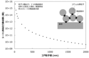
- FIG. 1 is a graph illustrating the relationship between the particle diameter of the core particles (core particle diameter) and the number of contact points per sheet.
- FIG. 2 is a schematic cross-sectional view illustrating a conventional sintered state of particles.
- FIG. 3 is a schematic cross-sectional view illustrating the sintered state of nanoparticles according to this embodiment.
- FIG. 4 is a graph illustrating the relationship between the content of copper particles and the volume of the medium.
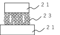
- FIG. 5A is a diagram for explaining the reason why the load during sintering is set to 40 kPa or more, and is a diagram showing the state before sintering.
- FIG. 5A is a diagram for explaining the reason why the load during sintering is set to 40 kPa or more, and is a diagram showing the state before sintering.
- FIG. 5A is a diagram for explaining the reason why the load during sintering is set to 40 kPa or more, and is a diagram showing the state before sintering
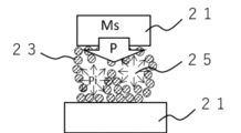
- FIG. 5B is a diagram for explaining the reason why the load during sintering is set to 40 kPa or more, and shows the case where no pressure is applied.
- FIG. 5C is a diagram for explaining the reason why the load during sintering is set to 40 kPa or more, and shows the case where pressure is applied.
- FIG. 6 is a TEM image of the particles obtained in the example.
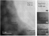
- FIG. 7 shows STEM images of particles obtained in the examples, and the STEM image on the right is an enlarged image of each lattice spacing shown in the STEM image on the left.
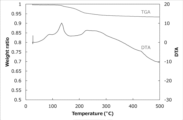
- FIG. 8 shows the results of TG-DTA measurement in the example.
- FIG. 9 is a diagram showing a procedure for producing a sample for evaluating the bonding and firing process of the embodiment.
- FIG. 9 is a diagram showing a procedure for producing a sample for evaluating the bonding and firing process of the embodiment.
- FIG. 10A is a schematic diagram of a copper test piece used to prepare a sample for evaluating bonding and firing in the examples.
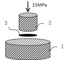
- FIG. 10B is a schematic diagram illustrating hot pressing in the bonding and firing evaluation test in the examples.
- FIG. 10C is a schematic cross-sectional view illustrating a method for evaluating the bonding and firing in the examples.
- FIG. 11 is a diagram showing the results of a bonding and firing evaluation test (pressure of 15 MPa, bonding time of 15 minutes) in the example.
- CuO, Cu 2 O, Cu 4 O 3 , Cu 8 O, and Cu 64 O, Cu 64 O and Cu 8 O have a lower ratio of oxygen atoms and are less stable than other copper oxides, and are therefore reduced to metallic copper with low energy.
- These copper oxides have a longer interatomic distance than metallic copper, and the reduction reaction to metallic copper accompanied by a change in crystal structure facilitates the diffusion of copper atoms and dramatically promotes the sintering of particles.
- the paste Since low-temperature sintering is easy when copper particles containing the above-mentioned copper oxide are used in a paste, the paste is considered to be useful as a conductive paste for printed electronics, etc., or as a bonding paste. Therefore, as an application of the above-mentioned copper oxide-coated copper particles, an evaluation was first carried out as a die-attach paste. As a result, it was found that the higher the concentration of the copper oxide-coated copper particles contained in the paste, the relatively lower the concentration of the dispersion medium, and the more the occurrence of voids and cracks due to the evaporation of the dispersion medium can be suppressed, and the adhesive strength is increased.
- the size of the copper particles which are the cores of the copper oxide-coated copper particles, is preferably 20 nm or more, more preferably more than 20 nm and less than 2 ⁇ m, from the following viewpoints.
- the reason for setting the average particle size of the core copper particles to 20 nm or more is as follows. The smaller the size of the fine particles and nanoparticles, the higher the cohesive force becomes, making it difficult to easily disperse them in a medium. Therefore, from the viewpoint of uniform and easy dispersion and stabilizing the dispersion state, the average particle size of the core copper particles is set to 20 nm or more.
- the core copper particles are required to be highly crystalline from the viewpoint of being used as a joining material.
- the crystallite size of the submicron-sized copper fine particles obtained by these methods is about 50 nm.
- the liquid-phase reduction method which is a low-temperature synthesis method
- submicron-sized copper fine particles can be obtained with a crystallite size of 17 to 50 nm by devising the synthesis method.
- the crystallite size of the core copper particles is at least 20 nm, and preferably 40 nm or more to obtain a sintered body with higher strength. Therefore, the average particle size of the core copper particles is set to 20 nm or more (because it is impossible for the particle size to be smaller than the crystallite size).
- the average particle size of the core copper particles is set to 20 nm or more. From the viewpoint of the above-mentioned crystallite size, the average particle size of the core copper particles is preferably 40 nm or more.
- the sintered body is a structure in which the core particles are necked and bonded by sintering the shell nanoparticles.
- Figure 1 is a diagram that summarizes the relationship between the particle diameter of the core particles (core particle diameter) and the number of sintered contacts (number of contacts per sheet) assuming the sheet-shaped bonding material A in the examples described below.
- the average particle diameter of the core copper particles is set to less than 2 ⁇ m.
- the surface roughness of copper foil for semiconductors is about 1 to 3 ⁇ m, and from the viewpoint of expecting an anchor effect on the copper foil for semiconductors, it is preferable to set the average particle diameter of the core copper particles to less than 2 ⁇ m.
- the average particle diameter of the core copper particles is preferably 300 nm or less.
- At least one of Cu 64 O and Cu 8 O forming the shell of the copper oxide-coated copper particle is in the form of a plurality of particulates, and the average particle size of the particulates is 1 nm or more, preferably more than 1 nm and 20 nm or less.
- the advantages of the shell of this embodiment being composed of nanoparticles having a size of 1 nm or more and 20 nm or less as described above over the conventional technology will be described below with reference to FIG. 2 and FIG. 3.
- sintering of a plurality of particles occurs at points as shown in the upper part of FIG.
- the copper oxide-coated copper particle of this embodiment in which the shell is composed of multiple copper oxide particles with an average particle size of 1 nm or more and 20 nm or less, is suitable as a bonding material.
- the thickness of the shell (the thickness of the deposit of the plurality of particulates) may be, for example, 1 to 20 nm.
- the shell containing one or more fine copper oxides of Cu 64 O and Cu 8 O is sintered in the process of being reduced to copper, but since its crystallinity is not as high as that of the core copper particles, if the shell is too thick, there is a concern that the mechanical strength will decrease. From these viewpoints, it is preferable that the shell thickness is 20 nm or less as described above.
- the fine copper oxide forming the shell of the fine copper oxide-coated copper particle may be a mixture of fine copper oxide particles of different sizes, for example, a mixed particle of one or more of Cu 64 O and Cu 8 O having an average particle size of 1 nm to 20 nm and Cu 64 O having an average particle size of 0.1 ⁇ m to 1 ⁇ m.
- the shell is permitted to contain a small amount of copper oxide such as CuO, Cu2O , etc., used in the raw materials, at a level that does not inhibit sinterability or electrical conductivity, in addition to one or more fine copper oxides of Cu64O and Cu8O .
- the shell does not contain copper oxide such as CuO, Cu2O , etc., used in the raw materials.
- the shell is preferably formed of fine copper oxide particles having an average particle size of 1 nm to 20 nm and consisting of one or more of Cu64O and Cu8O , and more preferably formed of fine copper oxide particles consisting of Cu64O or consisting of Cu64O and Cu8O , and having an average particle size of 1 nm to 20 nm.
- the copper particles coated with copper oxide can be produced by the method described below, but is not limited to this method and may be produced by a method different from the method described below.
- a method for producing core-shell type fine copper oxide-coated copper particles includes a copper particle as a core and a shell containing one or more fine copper oxides of Cu 64 O and Cu 8 O (the one or more fine copper oxides of Cu 64 O and Cu 8 O are fine copper oxide particles having an average particle size of 1 nm or more and 20 nm or less), the method comprising the steps of:
- the method includes preparing copper oxide-coated copper raw material particles having a copper raw material particle as a core and a copper oxide coating containing at least one of CuO and Cu 2 O as a shell, and mixing the copper oxide-coated copper raw material particles with a solution containing an amine compound and a complexing agent, adding a reducing agent, and reacting in an oxygen-containing atmosphere.
- the conditions of the above-mentioned production method are described in detail below.
- copper oxide-coated copper raw material particles are prepared, which have a copper raw material particle as the core and a copper oxide coating containing at least one of CuO and Cu 2 O as the shell.
- the particles are preferably core-shell type copper oxide-coated copper raw material particles having a copper raw material particle as the core and coated with copper oxide preferably consisting of at least one of CuO and Cu 2 O, more preferably with copper oxide consisting of Cu 2 O.
- Copper oxide-coated copper raw material particles of this configuration are suitable because a reduction reaction from copper oxide to copper and an oxidation reaction from copper to fine oxides occur on the surface of the core copper particle in the reaction step described below, making it easier to obtain the desired core-shell type particles.
- the copper oxide-coated copper raw material particles commercially available products may be used, or particles on which a surface oxide film is formed by natural oxidation of copper particles may be used, or particles on which a surface oxide film is formed by oxidation treatment of the copper particle surface may be used.
- a mixture obtained by adding copper oxide containing one or more of CuO and Cu 2 O (for example, copper oxide in powder form) to a dispersion containing the copper raw material particles, for example, by applying it to copper raw material particles on which no or almost no copper oxide is formed on the surface may be used as the raw material particles.
- This form is not necessarily a suitable raw material because the surface of the core copper particles is not necessarily covered with copper oxide, but it is possible to obtain similar particles more easily.
- the surface oxide film formed by natural oxidation is formed only when the copper particles are present in the atmosphere. Therefore, it is considered that commercially available copper particles are also naturally oxidized by being present in the atmosphere, and the particles on which a surface oxide film is formed by natural oxidation of the copper particles also include commercially available copper particles.
- the core copper raw material particles preferably have an average particle size of, for example, 20 nm or more and less than 2 ⁇ m for the same reasons as the average particle size of the core copper particles described above.
- the copper oxide coating containing at least one of CuO and Cu 2 O present on the surface of the core copper raw material particles may have a coating thickness of 20 nm or less.
- particle size refers to the primary particle size and the circle equivalent diameter
- average particle size refers to the median diameter of 150 or more particles randomly selected from a SEM image or a TEM image.
- the copper oxide coating containing one or more of CuO and Cu 2 O (preferably copper oxide composed of Cu 2 O) present on the surface of the copper oxide-coated copper raw material particle is sufficient even if it is an oxide coating at a natural oxidation level that cannot be detected by X-ray diffraction.
- the copper oxide coating of the copper oxide-coated copper raw material particle may be more than the natural oxide coating.
- the proportion of copper oxide containing one or more of CuO and Cu 2 O in the copper oxide-coated copper raw material particle can be 1 mass % or more.
- the copper oxide-coated copper raw material particle may be actively oxidized.
- the particles containing one or more fine copper oxides of Cu 64 O and Cu 8 O tend to exist as a single aggregate in addition to forming the shell.
- a shell containing one or more fine copper oxides of Cu 64 O and Cu 8 O has lower crystallinity when sintered at a low temperature compared to a highly crystalline core copper particle, so that a thick shell may cause a decrease in mechanical strength.
- the proportion of copper oxide containing one or more of CuO and Cu 2 O in the copper oxide-coated copper raw material particles is preferably 10 mass% or less.
- reaction step The copper oxide-coated copper raw material particles are mixed with a solution containing an amine compound and a complexing agent, and then a reducing agent is added to cause a reaction.
- a reducing agent is added to cause a reaction.
- the copper oxide contained in the copper oxide-coated copper raw material particles is reacted with a complexing agent to form copper complex ions.
- the complexing agent can be carboxylic acids.
- carboxylic acids include formic acid, saturated fatty acids, unsaturated fatty acids, hydroxy acids, aromatic carboxylic acids, and terpene carboxylic acids. These may be monocarboxylic acids or dicarboxylic acids. These may be used alone or in combination of two or more.
- the aliphatic monocarboxylic acid may be either linear or branched, and may be either saturated aliphatic monocarboxylic acid or unsaturated aliphatic monocarboxylic acid.
- linear saturated aliphatic monocarboxylic acids include acetic acid (carbon number 2), propionic acid (carbon number 3), butyric acid (carbon number 4), valeric acid (carbon number 5), and caproic acid (carbon number 6).
- the aliphatic dicarboxylic acid may be either linear or branched, and may be either saturated or unsaturated.
- the aliphatic dicarboxylic acid may be used alone or in combination of two or more.
- Examples of the aliphatic dicarboxylic acid include adipic acid, pimelic acid, suberic acid, azelaic acid, sebacic acid, 1,0-nonanedicarboxylic acid, 1,10-decanedicarboxylic acid, brassylic acid, 1,12-dodecanedicarboxylic acid, 1,13-tridecanedicarboxylic acid, thapsic acid, 1,15-pentadecanedicarboxylic acid, and 1,16-hexadecanedicarboxylic acid.
- aromatic carboxylic acid examples include benzoic acid, phthalic acid, isophthalic acid, terephthalic acid, hemimellitic acid, trimellitic acid, and trimesic acid.
- Terpene carboxylic acids that can be used include those contained in rosin, etc. Examples include abietic acid, neoabietic acid, palustric acid, pimaric acid, isopimaric acid, and desidroabietic acid.
- acetic acid as a complexing agent, as it is easy to handle and easy to process after the reaction.
- the amount of the complexing agent used in the reaction is not particularly limited, but from the viewpoint of promoting the formation of copper complex ions in order to promote the production of Cu 64 O and Cu 8 O, the amount of the complexing agent added is preferably 0.05 to 15 times, in terms of a molar ratio, relative to the copper contained in the copper oxide-coated copper raw material particles as the starting material, and may be 2 to 15 times, in terms of a molar ratio.
- a compound having an amino group (hereinafter referred to as "amine compound") is added as a protective agent.
- the amine compound also contributes to the formation of copper complex ions.
- the amine compound is not particularly limited, and it is preferable to use, for example, alkanolamine, diamine, aminocarboxylic acid, etc. Among them, it is more preferable to use alkanolamine.
- alkanolamine examples include 2-amino-1-butanol, 1-amino-2-propanol, 2-amino-2-ethyl-1,3-propanediol, 2-amino-2-hydroxymethyl-1,3-propanediol, 1,3-diamino-2-propanol, 1-amino-2-butanol, and 2-aminoethanol.
- the amount of the amine compound used in the reaction is not particularly limited, but from the viewpoint of promoting the production of Cu 64 O and Cu 8 O, the molar ratio of the amine compound to the copper contained in the copper oxide-coated copper raw material particles is preferably 0.1 or more, and may be 5 or more. The molar ratio may be, for example, 20 or less.
- solvent is not particularly limited, and examples of the solvent that can be used include polyhydric alcohols such as ethylene glycol, lower alcohols such as methanol, ethanol, and 2-propanol, ketones such as acetone, and water.
- the reducing agent is not particularly limited, and hydrazine-based reducing agents such as hydrazine, hydrazine hydrochloride, hydrazine sulfate, and hydrazine hydrate, citric acid, ascorbic acids, borohydride salts such as sodium borohydride, etc. can be used.
- the reducing agent can be added after the raw materials containing the copper oxide-coated copper raw material particles, the complexing agent, the amine compound, and the solvent are charged and mixed. After the reducing agent is added, stirring can be performed until the desired formation of fine copper oxide is confirmed, and preferably stirring is performed until the reducing agent disappears to allow the reaction to proceed sufficiently.
- the addition of the reducing agent may generate heat, such as a decomposition reaction of hydrazine, and the temperature of the reaction solution may rise.
- a temperature control means such as cooling the reaction solution, so that the reaction proceeds at 50° C. or less.
- the atmosphere during the reaction is limited to an oxygen-containing atmosphere such as air, and it is necessary to constantly expose the reaction vessel to the oxygen-containing atmosphere during the reaction. If the reaction vessel is in an inert gas atmosphere such as nitrogen gas or argon gas, or if the reaction vessel is sealed in air, the reaction to form the oxide Cu64O or Cu8O does not proceed, and copper particles are formed, which is not preferable.
- the method for producing fine copper oxide-coated copper particles may further include steps other than those described above.
- a purification step, a drying step, etc. may be included.
- purification is preferably performed using a washing solvent.
- the washing solvent is not particularly limited, and for example, an organic solvent such as N,N-dimethylacetamide, toluene, or hexane can be used.
- the proportion of copper particles coated with fine copper oxide in the sheet-shaped bonding material is more than 85% by mass.
- the reason for determining the proportion of copper particles coated with fine copper oxide in the sheet-shaped bonding material is described below.
- the sheet-shaped bonding material is composed of copper particles and a medium
- the relationship between the copper particle content (mass%) and the medium volume (volume%) is as shown in Figure 4.
- the medium is assumed to be a liquid or solid such as a resin, and the specific gravity range of these is approximately 0.8 to 2. Since the volume of the medium varies depending on the specific gravity, Figure 4 plots the relationship between the copper particle content (mass%) and the medium volume (volume%) for three representative cases of medium specific gravity of 1.0, 1.5, and 2.0.
- the medium volume is 44% by volume when the specific gravity is 2.0, 51% by volume when the specific gravity is 1.5, and 61% by volume when the specific gravity is 1.0.
- the interparticle voids of the core copper particles are 26% by volume even in the case of closest packing, and 35.9 to 44% by volume in the case of random packing. From the above, when a medium with a specific gravity of 2.0, which has the lowest medium volume, is used, if the copper content is 85% by mass or less, the volume of the medium exceeds the volume of the interparticle voids, and the probability of contact between the particles decreases.
- the particles In order for copper fine particles to be sintered, the particles need to come into contact with each other, but when the probability of contact between the particles is low, the possibility of sintering being hindered increases. Furthermore, if the medium is added in an amount that exceeds the interparticle voids, voids tend to remain after the medium is removed by volatilization or thermal decomposition, and the strength of the sintered structure decreases. In addition, when the medium is liquid, if the interparticle voids are filled with the medium at 85% by mass or less, it exhibits viscoelastic behavior, and it is difficult to process it into a sheet in the first place. Therefore, the proportion of copper particles coated with fine oxide in the sheet-shaped bonding material is set to be more than 85% by mass.
- the proportion of copper particles coated with copper oxide in the sheet-shaped bonding material is preferably 90% by mass or more. From the viewpoint of increasing the adhesive strength, the higher the proportion of copper particles coated with copper oxide in the sheet-shaped bonding material, the more preferable, but the above proportion can be, for example, 98% by mass or less.
- the sheet-shaped bonding material of this embodiment may contain, in addition to the copper particles coated with copper oxide and the medium, a single copper particle or a metal atom complex such as a copper cluster, as long as the effect of this embodiment is not impaired.
- the sheet-shaped bonding material of this embodiment may contain additives such as a dispersant as necessary, as long as the effect of this embodiment is not impaired.
- additives such as a dispersant as necessary, as long as the effect of this embodiment is not impaired.
- Known materials can be used as additives.
- the total proportion of the medium and other ingredients in the sheet-like bonding material is 15% by mass or less, more preferably 10% by mass or less, and even more preferably 5% by mass or less.
- the thickness of the sheet-like bonding material according to this embodiment can be set appropriately according to the desired bonded body.
- the thickness is preferably 1 ⁇ m or more and 1 mm or less.
- the surface roughness of copper foil for semiconductors is about 1 to 3 ⁇ m, and in order to obtain a bonded body with high strength integrated with the substrate, the bonding sheet needs to have a sufficient thickness to absorb this unevenness. Therefore, the thickness is preferably 1 ⁇ m or more.
- the thickness is preferably 1 mm or less.
- the thickness may further be 0.5 mm or less, further 0.3 mm or less, further 0.10 mm or less, further 0.050 mm or less, or even 0.020 mm or less.
- the method for producing the sheet-shaped bonding material is not limited, and it can be produced, for example, by the following method.
- a slurry containing a washing solvent e.g., N,N-dimethylacetamide, toluene, hexane, etc.
- a washing solvent e.g., N,N-dimethylacetamide, toluene, hexane, etc.
- copper oxide-coated copper fine particles obtained in the refining step in the production of fine copper oxide-coated copper particles is solvent-substituted with an alcohol solvent such as ethanol, and centrifuged to remove the supernatant alcohol solvent, thereby obtaining a wet cake of fine copper oxide-coated copper particles.
- substitution with an alcohol solvent is not necessarily required, slurries of non-polar solvents such as toluene and hexane in particular are not soluble in many dispersion media described in detail in the next section, so it is important to substitute with an alcohol as a dissolution aid before adding a dispersion medium in order to obtain a highly dispersible mixture.
- amines such as 2-(dimethylamino)ethanol, N-butyldiethanolamine, N-methyldiethanolamine, N-ethyldiethanolamine, diethanolamine, triethanolamine, 1-[bis(2-hydroxyethyl)amino]-2-propanol, triethanolamine, ethylenediamine-N,N,N',N'-tetraethanol
- glycols such as ethylene glycol, diethylene glycol, triethylene glycol, tetraethylene glycol, hexaethylene glycol, polyethylene glycol, propylene glycol, dipropylene glycol, tripropylene glycol, tetrapropylene glycol, polypropylene glycol (diol type, triol type); and glycerol; and agitation and dispersion is performed to obtain a paste.
- the agitation and dispersion can be performed using a dispersing machine.
- dispersing machines include a twin-shaft kneader, a triple roll mill, a planetary mixer, a rotation-revolution type agitating device, an ultra-high pressure dispersing machine, a thin film rotating type high-speed mixer, a ball mill, and a bead mill.
- the obtained paste is then held at room temperature in a vacuum until there is no mass change to remove the alcohol solvent, thereby obtaining a powder mixture of copper particles coated with copper oxide and a medium derived from the dispersion medium, in which the proportion of copper particles coated with copper oxide exceeds 85% by mass.
- the powder mixture is thoroughly kneaded to obtain a slightly sticky powder.
- kneading machines include single-axis or double-axis continuous kneaders, batch kneaders using roll mills, mortars, automatic mortars, and Huber-Marler machines.
- the powder is then molded by cold rolling. For example, the powder is sandwiched between PTFE sheets, pre-rolled with a rolling pin, and then press molded to obtain a sheet-like bonding material of the desired thickness.
- the molded body obtained by the press molding is sandwiched between thin stainless steel plates and rolled in stages using a roll press to obtain a thinner sheet-like bonding material of the desired thickness, for example, a thickness of about 0.05 to 0.4 mm.
- the sheet-like bonding material may be punched to the desired size and shape using a die or punch, if necessary.
- the present embodiment also includes a method for producing a bonded body using the sheet-like bonding material.
- the method for producing the bonded body includes the steps of: disposing the sheet-like bonding material between a first member and a second member to obtain a laminate; and heating the laminate at 100 to 500° C. to bond the first member and the second member via the sintered product of the sheet-like bonding material.
- the bonding can be easily performed by simply disposing the sheet-like bonding material between the first member and the second member, and there is no need to perform a coating process such as printing or spraying on the surfaces of the members.
- a coating process such as printing or spraying on the surfaces of the members.
- the sheet-like bonding material is placed between the first member and the second member to obtain a laminate.
- the material, shape, etc. of the first member and the second member constituting the laminate are not limited and can be determined according to the desired bonded body.
- At least one of the first member and the second member may be a semiconductor element such as an IGBT, a diode, a power MOSFET, a power switch, a MOS-FET, a thyristor, a logic, a sensor, an analog integrated circuit, an LED, a semiconductor laser, a rectifier, an oscillator, etc., and may be a member other than a semiconductor element such as a lead frame, a metal plate-attached ceramic substrate (e.g., DBC), a semiconductor element mounting base material such as an LED package, a copper ribbon, a metal block, a power supply member such as a terminal, a heat sink, a water-cooled plate, etc.
- a semiconductor element such as an IGBT, a diode, a power MOSFET, a power switch, a MOS-FET, a thyristor, a logic, a sensor, an analog integrated circuit, an LED, a semiconductor laser, a rectifier, an oscill
- At least one of the first member and the second member may be a semiconductor chip including the semiconductor element. At least one of the first member and the second member is preferably a semiconductor element.
- the laminate can be formed by sandwiching the sheet-like bonding material of this embodiment between the substrate and the semiconductor chip as the first member and the second member.
- a metal layer such as a metal plating may be formed as long as the desired characteristics are not impaired. Examples of metal elements constituting the metal layer include nickel, palladium, copper, silver, gold, platinum, lead, tin, cobalt, zinc, manganese, aluminum, titanium, chromium, iron, and molybdenum.
- the laminate is heated at a heating temperature of 100 to 500°C. If the sheet-shaped bonding material of this embodiment is used, sintering can be performed at a low temperature, so heating to 100°C or higher is sufficient.
- the heating temperature is preferably 150°C or higher.
- the heating temperature is preferably 500°C or lower.
- the holding time at the heating temperature may be appropriately determined from the viewpoint of obtaining a sintered product depending on the size of the target bonded body, the amount of the sheet-shaped bonding material used, etc.
- the holding time at the heating temperature may be, for example, 1 minute or more and 60 minutes or less. If the sheet-shaped bonding material of this embodiment is used, sintering can be promoted, so the holding time may be 30 minutes or less, or even 20 minutes or less.
- the heating may be performed while pressurizing the laminate, or may be performed without pressurizing the laminate.
- Pressurizing the laminate can suppress the growth of bubbles and cracks caused by thermal expansion of voids in the laminate. Furthermore, pressurizing and heating can produce a bonded body with high adhesive strength in a short period of time.
- it is preferable to heat it while applying a load of 40 kPa or more. The reason why the load is preferably 40 kPa or more is explained below.
- the sheet is composed of copper particles coated with copper oxide and a medium, and the lower limit of the copper content is 85 mass%, so there may be interparticle voids.
- a pressure 27 in FIG. 5C, the image of pressure is expressed by a weight for the purpose of explanation, and the pressure method may be any method that is commonly used as described below) higher than the internal pressure increase that occurs during firing must be applied during firing.
- the temperature rise rate is slower than the assumed conditions above, and gas escapes from the sides of the sheet, so the internal pressure generated is smaller than the above calculated value, and there is no need to apply a load of 64 kPa.
- a pressure of about 40 kPa in order to obtain a sintered body with voids sufficiently suppressed, and more preferably a sintered body without voids. Therefore, the preferable load was set to 40 kPa or more as described above.
- the load is more preferably 1 MPa or more from the viewpoint of bonding the particles more closely, and even more preferably 10 MPa or more from the viewpoint of sintering in a shorter time.
- the pressurization and heat treatment can be performed, for example, by applying pressure to the laminate using a hot press or a jig, and then heating the laminate with a heating device such as a heater, infrared heating furnace, electromagnetic heating device, hot plate, or hot air heating furnace.
- the atmosphere in which the bonded body is manufactured, including the heating is preferably an inert atmosphere such as nitrogen or argon from the viewpoint of preventing oxidation, and a nitrogen atmosphere is preferable from the viewpoint of cost.
- an inert atmosphere such as nitrogen or argon from the viewpoint of preventing oxidation
- a nitrogen atmosphere is preferable from the viewpoint of cost.
- the present invention is not limited to this, and the manufacturing process may be carried out in air depending on the heating conditions, such as low temperature and short time.
- the method for manufacturing the bonded body is not limited as long as it includes the step of forming the laminate and the step of heating the laminate to bond the members together.
- Other steps include, for example, preparatory steps such as cutting the first member, the second member, and the sheet-like bonding material to the desired size and washing them in order to form the laminate.
- the method for manufacturing a bonded body of this embodiment can be applied to a method for manufacturing a semiconductor device. That is, at least one of the first member and the second member can be a semiconductor element, and the bonded body can be a semiconductor device.
- This embodiment also includes a joined body including a first member, a second member, and a sintered material of a sheet-like joining material that joins the first member and the second member.
- the first member and the second member in the joined body are as described above.
- the sheet-like joining material which is a precursor of the sintered material, is as described above.
- the sintered material of the sheet-like joining material refers to a sintered material obtained by heating the sheet-like joining material under the above-mentioned conditions, for example.
- a metal layer such as a metal plating formed on the surface of the member may be interposed between at least one of the first member and the sintered material of the sheet-like joining material and the second member and the sintered material of the sheet-like joining material, as long as the desired characteristics are not hindered.
- the metal constituting the metal layer include the metal elements described above.
- the bonded body according to this embodiment can achieve a high adhesive strength of 30 MPa or more, or even 50 MPa or more, or even 70 MPa or more, when the adhesive strength is measured by the method shown in the examples described below.
- An example of the bonded body of this embodiment is a semiconductor device in which at least one of the first member and the second member is a semiconductor element.
- Specific examples of semiconductor elements include those mentioned above.
- Y mass of particles in the slurry
- Ms Slurry mass
- Vs Slurry volume ( cm3 )
- ⁇ m Solvent density (g/cm 3 )
- Cu copper density (g/cm 3 )
- the obtained product was observed under an electron microscope.
- an SEM image was obtained using a scanning electron microscope (SEM, JSM-6701F manufactured by JEOL, accelerating voltage 15 kV)
- a TEM image was obtained using a transmission electron microscope (TEM, JEM-2000FX manufactured by JEOL, accelerating voltage 200 kV)
- a STEM image was obtained using a scanning transmission electron microscope (STEM, JEM-ARM200F, accelerating voltage 200 kV).
- SEM scanning electron microscope
- STEM scanning transmission electron microscope
- the fine particles of the above configuration can easily obtain fine copper oxide nanoparticles on the surface of submicron copper particles, which was impossible to achieve by conventional mixing methods.
- the core-shell fine copper oxide-containing particles are reduced to metallic copper by heating, and the Cu 64 O and Cu 8 O nanoparticle shells densely connect adjacent copper particle cores, dramatically promoting sintering between core particles.
- the obtained sintered product has a structure in which highly crystalline copper particle cores are densely connected, and is expected to have high mechanical strength.
- the powder mixture was thoroughly kneaded in a mortar to obtain a slightly sticky powder.
- the powder was spread on a PTFE sheet (manufactured by Nitto Denko, thickness 0.1 mm) to a square of several cm, sandwiched between PTFE sheets from above, and stretched into a sheet shape using a metal round bar on a smooth table. This was press molded to obtain a uniform sheet-like bonding material A with a thickness of about 0.3 mm.
- this sheet-like bonding material A was sandwiched between stainless steel thin plates (thickness 0.1 mm) and rolled in stages using a roll press to obtain a sheet-like bonding material B with a thickness of about 0.15 mm.
- the content of copper oxide-coated copper particles contained in these sheet-like bonding materials is substantially the same as that of the above mixture, that is, 93.8% by mass.
- a sheet 3 with a diameter of 6 mm cut from each of the sheet-like bonding material A and the sheet-like bonding material B was sandwiched between a copper test piece 1 with a diameter of 12 mm and a copper test piece 2 with a diameter of 5 mm and bonded together as shown in Figure 10B.
- the two bonded copper test pieces were then heated at a high speed of 90°C/min to the ultimate temperature (three levels: 150°C, 200°C, and 250°C) in a hot press while a load of 15 MPa was applied in the direction of the arrows in Figure 10B.
- the temperature was then held for 15 minutes, after which the piece was removed from the hot press and rapidly cooled to room temperature, yielding a sample for evaluation of bonding and sintering in which the copper test pieces were bonded together by the sintered sheet-like bonding material.
- a high-concentration copper bonding material with few voids and cracks due to the volatilization of the dispersion medium can be easily obtained, and thereby, when heated, the Cu 64 O and Cu 8 O nanoparticle shells densely sinter and connect the adjacent copper microparticle cores to each other to obtain a strong bond as shown in Figure 3, and high adhesive strength can be obtained, and the characteristics of the core-shell fine copper oxide-containing particles can be fully utilized.
- the temperature was raised to 200°C in about 20 minutes while nitrogen gas was supplied into the tube at a flow rate of 1 L/min, and the tube was held at 200°C for 1 hour, and then naturally cooled to room temperature to obtain a substrate on which a sintered product of the sheet-shaped bonding material was formed.
- the series of operations from the installation of the sheet-shaped bonding material A to holding the evaluation temperature and naturally cooling to room temperature were performed in a nitrogen atmosphere.
- the volume resistivity was measured by averaging six points using a resistivity meter (Loresta GP, ASP Probe, manufactured by Mitsubishi Chemical Analytical).
- the resistivity correction factor RCF which corrects the shape factor of the coating film, was calculated using a value calculated using Loresta GP, and the film thickness of the sintered product was calculated from an image of a cross section obtained by breaking the substrate on which the sintered product was formed, observed with a microscope (Keyence Digital Microscope VHX-7000).
- the volume resistivity of the sintered product was 4 ⁇ 10 ⁇ 6 ⁇ cm. This value was about 2.5 times the resistivity (1.55 ⁇ 10 ⁇ 6 ⁇ cm) of bulk copper at 0° C., which was an extremely good value.
- the sheet-shaped bonding material of the present invention can be used as a conductive sheet and exhibits extremely high conductive properties.
- the fine copper oxide-coated copper particles contained in the sheet-shaped bonding material of this embodiment have a core portion made of metallic copper, and the content of copper oxide that can increase the resistance of CuO, Cu 2 O, etc. is reduced, so that the sintered product (bonded part) obtained by sintering the fine copper oxide-coated copper particles exhibits high electrical conductivity and does not inhibit the properties of electronic parts and electronic devices as a bonded body.
- Aspect 1 of the present invention is A copper particle coated with fine copper oxide, the copper particle having a core of a copper particle and a shell containing one or more fine copper oxides selected from Cu 64 O and Cu 8 O; A medium; The content of the fine copper oxide-coated copper particles is more than 85 mass %.
- Aspect 2 of the present invention is In the sheet-like bonding material according to aspect 1, the fine copper oxide of at least one of Cu 64 O and Cu 8 O is a fine copper oxide particle having an average particle size of 1 nm or more and 20 nm or less.
- Aspect 3 of the present invention is The sheet-like bonding material according to aspect 1 or 2, wherein the core copper particles have an average particle size of 20 nm or more and 2 ⁇ m or less.
- Aspect 4 of the present invention is The sheet-like bonding material according to any one of Aspects 1 to 3, having a thickness of 1 ⁇ m or more and 1 mm or less.
- Aspect 5 of the present invention is A method for producing a joined body, comprising: disposing the sheet-like joining material according to any one of Aspects 1 to 4 between a first member and a second member to obtain a laminate; and heating the laminate at 100 to 500° C. to join the first member and the second member via a sintered product of the sheet-like joining material.
- Aspect 6 of the present invention is 6.
- Aspect 7 of the present invention is 7.
- Aspect 8 of the present invention is A joined body including a first member, a second member, and a sintered product of the sheet-like joining material according to any one of Aspects 1 to 4, which joins the first member and the second member.
- Aspect 9 of the present invention is At least one of the first member and the second member is a semiconductor element, and the bonded body is a semiconductor device.
- the sheet-like bonding material according to this embodiment is preferably used, for example, in the manufacture of electronic components, which involves bonding of components that constitute the electronic components.
- it is preferably used in the manufacture of semiconductor devices, such as SiC power semiconductors, which require high adhesive strength between components.
Landscapes
- Chemical & Material Sciences (AREA)
- Engineering & Computer Science (AREA)
- Manufacturing & Machinery (AREA)
- Mechanical Engineering (AREA)
- Composite Materials (AREA)
- Materials Engineering (AREA)
- Inorganic Chemistry (AREA)
- Nanotechnology (AREA)
- Organic Chemistry (AREA)
- Physics & Mathematics (AREA)
- Dispersion Chemistry (AREA)
- Spectroscopy & Molecular Physics (AREA)
- Powder Metallurgy (AREA)
Abstract
Description
コアである銅粒子と、Cu64OとCu8Oのうちの1以上の微酸化銅を含むシェルとを備え、前記Cu64OとCu8Oのうちの1以上の微酸化銅は、平均粒径が1nm以上20nm以下の微酸化銅粒子である、微酸化銅被覆銅粒子と、
媒質とを含み、
前記微酸化銅被覆銅粒子の含有量が85質量%超である、シート状接合用材料である。
前記コアである銅粒子は、平均粒径が20nm以上2μm未満である、態様1に記載のシート状接合用材料である。
厚さが1μm以上1mm以下である、態様1または2に記載のシート状接合用材料である。
態様1~3のいずれか1つに記載のシート状接合用材料を、第1部材と第2部材の間に配置して積層体を得ること、および
前記積層体を100~500℃で加熱し、前記シート状接合用材料の焼結物を介して第1部材と第2部材を接合すること
を含む、接合体の製造方法である。
前記積層体の加熱を、40kPa以上の加圧下で行う、態様4に記載の接合体の製造方法である。
前記第1部材と前記第2部材の少なくとも1つは半導体素子であり、前記接合体は半導体装置である、態様4または5に記載の接合体の製造方法である。
第1部材と、第2部材と、前記第1部材と前記第2部材を接合する、態様1~3のいずれか1つに記載のシート状接合用材料の焼結物とを含む、接合体である。
前記第1部材と前記第2部材の少なくとも1つは半導体素子であり、前記接合体は半導体装置である、態様7に記載の接合体である。
シート状接合用材料に含まれる微酸化銅被覆銅粒子、媒質について順に説明する。
[微酸化銅被覆銅粒子]
本実施形態のシート状接合用材料に含まれる微酸化銅被覆銅粒子は、コアである銅粒子と、Cu64OとCu8Oのうちの1以上の微酸化銅(このCu64OとCu8Oのうちの1以上の微酸化銅は、平均粒径が1nm以上20nm以下の微酸化銅粒子である)を含むシェルとを備えた、コアシェル状微酸化銅含有粒子(微酸化銅被覆銅粒子)である。なお「銅粒子」における「銅」のように単に「銅」という場合は金属銅をいい、酸化銅と区別される。このコアシェル状微酸化銅含有粒子、及び還元剤としても作用する媒質が、シート状接合用材料に含まれることで、シェルを構成する、加熱により金属銅へと還元されるCu64O及びCu8Oのナノ粒子が、隣接する銅微粒子コア同士を密に接続し、コア粒子間の焼結が飛躍的に促進される。得られた焼結物は、結晶性の高い銅微粒子コアが密に接続された構造となり、高い機械的強度が期待される。また、例えば従来の、Cu64O粒子とCu8O粒子のうちの少なくとも1つの微酸化銅粒子と、銅粒子と、銅クラスターとの組成物は、均一に分散し難かったが、上記コアシェル構造を有する微酸化銅被覆銅粒子では、上記分散の問題が解消されて、焼結時に、上述の通り、コアである銅粒子の表面のCu64O等の微酸化銅粒子間での焼結を促進させることができる。なお、特許文献2、5~7の銅粒子、銅微粒子は、上記のようなコアシェル状ではなく、組成物(混合粒子)等であって、上述した問題の解消に寄与し得ない。
本実施形態に係る、コアである銅粒子と、Cu64OとCu8Oのうちの1以上の微酸化銅(このCu64OとCu8Oのうちの1以上の微酸化銅は、平均粒径が1nm以上20nm以下の微酸化銅粒子)を含むシェルとを備えた、コアシェル型の微酸化銅被覆銅粒子の製造方法は、
銅原料粒子をコアとし、CuOとCu2Oのうちの1以上を含む酸化銅被膜をシェルとする、酸化銅被覆銅原料粒子を用意すること、および
前記酸化銅被覆銅原料粒子と、アミン系化合物および錯形成剤を含む溶液とを混合し、次いで還元剤を加え、酸素含有雰囲気で反応させることを含む。以下では、上記製造方法の条件について詳述する。
まず、銅原料粒子をコアとし、CuOとCu2Oのうちの1以上を含む酸化銅被膜をシェルとする、酸化銅被覆銅原料粒子を用意する。該粒子は、銅原料粒子をコアとし、好ましくはCuOとCu2Oのうちの1以上からなる酸化銅、より好ましくはCu2Oからなる酸化銅の被覆された、コアシェル型の酸化銅被覆銅原料粒子がよい。このような構成の酸化銅被覆銅原料粒子であれば、後述する反応工程で、酸化銅から銅への還元反応・銅から微酸化物の酸化反応が、コア銅粒子表面で生じるため、所望のコアシェル型粒子が得られやすくなり好適である。
前記酸化銅被覆銅原料粒子と、アミン系化合物および錯形成剤を含む溶液とを混合し、次いで還元剤を加えて反応させる。以下では、前述の通り反応に必要な錯形成剤等について説明する。
本実施形態では、酸化銅被覆銅原料粒子に含まれる酸化銅と錯形成剤を反応させ、銅の錯イオンを形成させる。この様に、酸化銅被覆銅原料粒子中の銅をイオン化させることにより、還元剤による還元の速度を、固体である酸化銅の還元よりも格段に速めることができる。前記錯形成剤として、カルボン酸類が挙げられる。カルボン酸類として、例えばギ酸、飽和脂肪酸、不飽和脂肪酸、ヒドロキシ酸、芳香族カルボン酸、テルペン系カルボン酸類等が挙げられる。これらは、モノカルボン酸、ジカルボン酸であってもよい。またこれらは、1種単独で用いてもよく、2種以上を組み合わせて用いてもよい。脂肪族モノカルボン酸は、直鎖状および分岐鎖状のいずれであってもよく、また飽和脂肪族モノカルボン酸および不飽和脂肪族モノカルボン酸のいずれであってもよい。直鎖状の飽和脂肪族モノカルボン酸として、酢酸(炭素数2)、プロピオン酸(炭素数3)、酪酸(炭素数4)、吉草酸(炭素数5)、カプロン酸(炭素数6)などが挙げられる。
アミノ基を有する化合物(以下、「アミン系化合物」という)を保護剤として添加する。アミン系化合物は、銅の錯イオン形成にも寄与する。アミン系化合物は、特に限定されず、例えばアルカノールアミン、ジアミン及びアミノカルボン酸等を用いることが好ましい。その中でも、アルカノールアミンを用いることがより好ましい。アルカノールアミンとしては、例えば、2-アミノ-1-ブタノール、1-アミノ-2-プロパノール、2-アミノ-2-エチル-1,3-プロパンジオール、2-アミノ-2-ヒドロキシメチル-1,3-プロパンジオール、1,3-ジアミノ-2-プロパノール、1-アミノ-2-ブタノール、2-アミノエタノール等が挙げられる。
溶媒としては、特に限定されず、例えばエチレングリコール等の多価アルコール類、メタノール、エタノール、2-プロパノール等の低級アルコール類、アセトン等のケトン類、水等を用いることができる。
還元剤としては、特に限定されず、ヒドラジン、塩酸ヒドラジン、硫酸ヒドラジン、抱水ヒドラジン等のヒドラジン系還元剤、クエン酸、アスコルビン酸類、水素化ホウ素ナトリウム等の水素化ホウ素酸塩等を用いることができる。還元剤の添加時期は、上記酸化銅被覆銅原料粒子、錯形成剤、アミン系化合物および溶媒を含む原料を投入し、混合後とすればよい。還元剤添加後、所望の微酸化銅の形成が確認されるまで攪拌を行えばよく、好ましくは還元剤が消失するまで撹拌を行い、十分反応させるのがよい。
微酸化銅被覆銅粒子の製造方法では、例えば還元剤としてヒドラジンを用いた場合に、ヒドラジンの分解反応など、還元剤の添加による発熱が生じ、反応溶液の温度が上昇する場合がある。反応溶液の温度上昇を抑えて、一旦形成されたCu64O及びCu8Oが金属銅に還元されることを抑制する観点から、反応は50℃以下で進むよう、反応溶液を冷却する等の温度制御手段を設けることが好ましい。例えば反応容器を水浴した状態で還元剤を添加することが好ましい。
反応時の雰囲気は、例えば大気中などの酸素含有雰囲気に限定され、反応中は常に当該酸素含有雰囲気に曝されている必要がある。窒素ガス、アルゴンガスなどの不活性ガス雰囲気とした場合、または大気中であっても反応容器を密閉した場合には、Cu64OあるいはCu8Oへの酸化物形成反応が進まず、銅粒子が形成されてしまうため好ましくない。
微酸化銅被覆銅粒子の製造方法は、上記以外の工程を更に含んでいてもよい。例えば、精製工程、乾燥工程等が含まれていてもよい。精製工程では、洗浄溶媒により精製することが好ましい。洗浄溶媒は特に限定されず、例えばN,N-ジメチルアセトアミド、トルエン、ヘキサン等の有機溶媒を用いることができる。
本実施形態のシート状接合用材料には、微酸化銅被覆銅粒子以外に、媒質が含まれる。媒質は、液状であってもよく、または固体状であってもよい。液状の媒質は、シート状接合用材料の製造で用いられた分散媒、溶媒等に起因するものであってもよい。固体状の媒質として、樹脂バインダー等が挙げられる。前記液状の媒質、前記固体状の媒質として公知の材料を用いることができる。前記液状の媒質として、例えばアミン類として、2-(ジメチルアミノ)エタノール、N-ブチルジエタノールアミン、N-メチルジエタノールアミン、N-エチルジエタノールアミン、ジエタノールアミン、トリエタノールアミン、1-[ビス(2-ヒドロキシエチル)アミノ]-2-プロパノール、エチレンジアミン-N,N,N',N'-テトラエタノール;グリコール類として、エチレングリコール、ジエチレングリコール、トリエチレングリコール、テトラエチレングリコール、ヘキサエチレングリコール、ポリエチレングリコール、プロピレングリコール、ジプロピレングリコール、トリプロピレングリコール、テトラプロピレングリコール、ポリプロピレングリコール(ジオール型、トリオール型):およびグリセロールのうちの1以上が挙げられる。
本実施形態のシート状接合用材料には、本実施形態の効果を阻害しない範囲内において、微酸化銅被覆銅粒子と媒質以外に、銅粒子単体、または銅クラスターの様な金属原子複合体が含まれていてもよい。また、本実施形態のシート状接合用材料には、本実施形態の効果を阻害しない範囲内において、必要に応じて分散剤等の添加剤が含まれていてもよい。添加剤として公知の材料を用いることができる。
シート状接合用材料の製造方法は限定されず、例えば次の方法で製造することができる。微酸化銅被覆銅粒子の製造における精製工程で得られた、洗浄溶媒(例えばN,N-ジメチルアセトアミド、トルエン、ヘキサン等)と、酸化銅被覆銅微粒子とを含むスラリーを、例えばエタノール等のアルコール溶媒に溶媒置換し、遠心分離して上澄みのアルコール溶媒を除去し、微酸化銅被覆銅粒子のウェットケーキを得ることが挙げられる。アルコール溶媒への置換は必ずしも必要ではないが、特にトルエン・ヘキサンなどの無極性溶媒のスラリーは、次項で詳述する多くの分散媒に溶解しないため、溶解助剤としてのアルコール類に置換してから、分散媒を加えることが、分散性の高い混合物を得るうえで重要である。
本実施形態には、前記シート状接合用材料を用いた接合体の製造方法も含まれる。
接合体の製造方法は、
前記シート状接合用材料を、第1部材と第2部材の間に配置して積層体を得ること、
および
前記積層体を100~500℃で加熱し、前記シート状接合用材料の焼結物を介して第1部材と第2部材を接合することを含む。本実施形態のシート状接合用材料を用いれば、接合を行うにあたり、第1部材と第2部材の間に該シート状接合用材料を配置すればよく、部材の表面に印刷、スプレー等の塗工処理を行う必要がなく、簡易に接合を行うことができる。以下、接合体の製造方法の各工程について説明する。
前記シート状接合用材料を、第1部材と第2部材の間に配置して積層体を得る。前記積層体を構成する第1部材と第2部材の材質、形状等については限定されず、所望の接合体に応じて決定することができる。第1部材と第2部材の少なくとも1つは、半導体素子として、IGBT、ダイオード、パワーMOSFET、パワースイッチ、MOS-FET、サイリスタ、ロジック、センサー、アナログ集積回路、LED、半導体レーザー、整流器、発信器等であり得、半導体素子以外の部材である、リードフレーム、金属板貼付セラミックス基板(例えばDBC)、LEDパッケージ等の半導体素子搭載用基材、銅リボン、金属ブロック、端子等の給電用部材、放熱板、水冷板等であり得る。第1部材と第2部材の少なくとも1つは、上記半導体素子を含む半導体チップであり得る。第1部材と第2部材の少なくとも1つは、好ましくは半導体素子である。例えば積層体は、第1部材と第2部材として基板と半導体チップの間に、本実施形態のシート状接合用材料を挟んで形成することができる。第1部材と第2部材のうちの1以上の、シート状接合用材料を形成させる表面には、所望とする特性を阻害しない限りにおいて、金属メッキ等の金属層が形成されていてもよい。前記金属層を構成する金属元素として例えば、ニッケル、パラジウム、銅、銀、金、白金、鉛、錫、コバルト、亜鉛、マンガン、アルミニウム、チタン、クロム、鉄、モリブデン等が挙げられる。
前記積層体を100~500℃の加熱温度で加熱する。本実施形態のシート状接合用材料を用いれば、低温で焼結することができるため、100℃以上に加熱すればよい。加熱温度は、好ましくは150℃以上である。一方、電子部品を構成する部材の耐熱温度等の観点から、加熱温度は500℃以下であることが好ましい。前記加熱温度での保持時間は、対象とする接合体のサイズ、シート状接合用材料の使用量等に応じて、焼結物を得る観点から適宜決定すればよい。上記加熱温度での保持時間は、例えば1分間以上であって、60分間以下とすることができる。本実施形態のシート状接合用材料を用いれば、焼結を促進させることができるため、保持時間を30分間以下、更には20分間以下とすることもできる。
本実施形態には、第1部材と、第2部材と、前記第1部材と前記第2部材を接合する、シート状接合用材料の焼結物とを含む、接合体も含まれる。接合体における第1部材と第2部材は前述の通りである。焼結物の前駆体であるシート状接合用材料について前述した通りである。シート状接合用材料の焼結物は、シート状接合用材料が例えば前述の条件で加熱されることにより得られた焼結物をいう。本実施形態の接合体は、第1部材-シート状接合用材料の焼結物-第2部材の順に接合、すなわち、第1部材とシート状接合用材料の焼結物、第1部材とシート状接合用材料の焼結物が直接接している態様の他、第1部材とシート状接合用材料の焼結物の間と、第2部材とシート状接合用材料の焼結物の間との少なくともいずれかに、所望とする特性を阻害しない限りにおいて、例えば部材の表面に形成された金属メッキ等の金属層が介在していてもよい。前記金属層を構成する金属として、前述した金属元素が挙げられる。
溶媒としてエチレングリコール(関東化学製)1388g(22.4mol)、保護剤(アミン系化合物)として1-アミノ-2-プロパノール(関東化学製)1182g(15.7mol)、錯形成剤として酢酸(純正化学製)473g(7.9mol)を反応容器に入れ、十分攪拌した後、出発原料として銅粒子(太陽日酸製TN-Cu100 粒子径50~200nm)を100g(1.6mol)添加した。なお、出発原料である前記市販品の銅粒子はCu2O層を有する酸化銅被覆銅原料粒子である。前記反応容器を水浴した状態で、還元剤としてヒドラジン一水和物(関東化学製)を788g(15.7mol)添加し、1100rpmにて攪拌しながら反応させた。反応は大気中にて実施した。反応後、N,N-ジメチルアセトアミド、トルエン、ヘキサンを用いて複数回の遠心分離による精製を行い、生成物を含むスラリーを得た。スラリー中の微酸化銅被覆銅粒子の質量は下記式(1)により計算した。

Y:スラリー中の粒子質量(g)
Ms:スラリー質量(g)
Vs:スラリー容積(cm3)
ρm:溶媒密度(g/cm3)
ρCu:銅密度(g/cm3)
得られた生成物の電子顕微鏡観察を行った。電子顕微鏡観察では、走査電子顕微鏡(SEM,日本電子製 JSM-6701F,加速電圧15kV)によりSEM像を取得し、透過電子顕微鏡(TEM,日本電子製 JEM-2000FX,加速電圧200kV)によりTEM像を取得し、更には走査型透過電子顕微鏡(STEM,JEM-ARM200F,加速電圧200kV)によりSTEM像を取得した。前記TEM、STEMでの観察は、微粒子が凝集しないように分散させた状態で行った。
合成した微酸化銅被覆銅粒子を含むスラリーの分散媒を、遠心分離によりヘキサンからエタノールへ置換した。これを更に遠心分離してエタノールの上澄みを除去し、微酸化銅被覆銅粒子のウェットケーキを得た。ウェットケーキ中の微酸化銅被覆銅粒子92.5質量部(式(1)で算出した値)に対して、分散媒としてトリエタノールアミン(富士フィルム和光純薬製)を7.5質量部添加した。添加後、自転公転ミキサー(シンキー製AR-100)を用いて4分攪拌し、次いで、薄膜旋回型高速ミキサー(プライミクス製フィルミックス56-L)を用いて断続的に3分の分散処理を行って分散処理後のペーストを得た。その後、常温真空中で、質量変化がなくなるまで保持してエタノールを除去し、微酸化銅被覆銅粒子と前記分散媒に由来の媒質との粉状混合物を得た。
島津製作所製TG/DTA同時測定装置を用い、3%水素・窒素混合ガス下、昇温速度5℃/minにて、得られた粉状混合物の熱重量・示差熱分析(TG-DTA)を行った。分析結果としてTG-DTA曲線を図8に示す。図8から、TGAが示す質量減少から、得られた混合物は93.8質量%の微酸化銅被覆銅粒子を含むことを確認した。
前処理として、前記粉状混合物を乳鉢により十分に混錬し、わずかに粘り気のある粉体を得た。この粉体を、PTFEシート(日東電工製、厚さ0.1mm)上に数cm四方に広げ、上からPTFEシートにて挟み込み、平滑な台の上で金属丸棒によりシート状になるように伸ばした。これをプレス成型して、厚さが約0.3mmの均一なシート状接合用材料Aを得た。更に、このシート状接合用材料Aをステンレス薄板(厚さ0.1mm)に挟み込み、ロールプレスにより段階的に圧延し、厚さ約0.15mmのシート状接合用材料Bを得た。なお、これらのシート状接合用材料に含まれる微酸化銅被覆銅粒子の含有量は、上記混合物と実質同じであり93.8質量%である。
得られたシート状接合用材料を用いて2つの銅試験片を貼り合わせ、シート状接合用材料の焼成により接着された接合焼成評価用サンプルを作製し、接着強度を測定した。
接合焼成評価用サンプルの作製手順は図9に示す通りである。まず厚さ5mmの無酸素銅板(C1020P)から、円形の銅試験片として、図10Aに示す通り、直径12mmの銅試験片1と直径5mmの銅試験片2とをそれぞれ切り出した。各銅試験片の表面を耐水研磨紙(SiCペーパー)P4000にて研磨した後、0.5μmアルミナ粉末の懸濁液を浸した琢磨布により鏡面仕上げを行い、脱脂して作製した。前記シート状接合用材料を貼り合わせる直前に、各銅試験片を2.5M塩酸に浸漬して表面の銅酸化被膜を除去し、純水、メタノールにて十分洗浄後、乾燥させた。
5kN材料試験機(島津製作所製)を用い、接合焼成評価用サンプルの接着強度を評価した。詳細には、図10Cに模式断面図を示す通り、試験片の塗工面に平行に、1mm/minの速度で荷重を印加し、銅試験片の破断荷重を接着強度として測定した。
(導電性評価用サンプルの作製)
厚さ1mmのアルミナ板(フルウチ化学製AO-5050)を5cm×2.5cmとなるよう切り出し、評価に用いるアルミナ基板とした。該アルミナ基板の表面に、2cm角に切り出したシート状接合用材料Aを載せ、アルミナ基板に十分密着させた。これを管状炉に投入し、3%水素/窒素混合ガスを1L/minの流量で管内に供給し、常温で30分以上ガス置換した。その後、窒素ガスを1L/minの流量で管内に供給した状態で、200℃まで約20分で昇温し、200℃で1時間保持した後、常温まで自然放冷して、シート状接合用材料の焼結物が形成された基板を得た。なお、上記シート状接合用材料Aの設置から、評価温度に保持し常温まで自然放冷するまでの一連の作業は窒素雰囲気中で行った。
焼結物の導電性評価のために、抵抗率計(三菱化学アナリティック製 ロレスタGP、ASPプローブ)を用いて6点平均により体積抵抗率を測定した。体積抵抗率の測定に際して、塗膜の形状要因を補正する抵抗率補正計数RCFはロレスタGPで計算した値を用い、焼結物の膜厚は、焼結物の形成された基板の破断により得られた断面を、顕微鏡(キーエンス製デジタルマイクロスコープVHX-7000)で観察した像から算出した。測定の結果、焼成物の体積抵抗率は4×10⁻⁶Ωcmであった。この値は、バルク銅の0℃における抵抗率(1.55×10⁻⁶Ωcm)の2.5倍ほどであり、極めて良好な値であった。
本発明の態様1は、
コアである銅粒子と、Cu64OとCu8Oのうちの1以上の微酸化銅を含むシェルとを備えた微酸化銅被覆銅粒子と、
媒質とを含み、
前記微酸化銅被覆銅粒子の含有量が85質量%超である、シート状接合用材料である。
本発明の態様2は、
前記Cu64OとCu8Oのうちの1以上の微酸化銅は、平均粒径が1nm以上20nm以下の微酸化銅粒子である、態様1に記載のシート状接合用材料である。
本発明の態様3は、
前記コアである銅粒子は、平均粒径が20nm以上2μm以下である、態様1または2に記載のシート状接合用材料である。
本発明の態様4は、
厚さが1μm以上1mm以下である、態様1~3のいずれか1つに記載のシート状接合用材料である。
本発明の態様5は、
態様1~4のいずれか1つに記載のシート状接合用材料を、第1部材と第2部材の間に配置して積層体を得ること、および
前記積層体を100~500℃で加熱し、前記シート状接合用材料の焼結物を介して第1部材と第2部材を接合すること
を含む、接合体の製造方法である。
本発明の態様6は、
前記積層体の加熱を、40kPa以上の加圧下で行う、態様5に記載の接合体の製造方法である。
本発明の態様7は、
前記第1部材と前記第2部材の少なくとも1つは半導体素子であり、前記接合体は半導体装置である、態様5または6に記載の接合体の製造方法である。
本発明の態様8は、
第1部材と、第2部材と、前記第1部材と前記第2部材を接合する、態様1~4のいずれか1つに記載のシート状接合用材料の焼結物とを含む、接合体である。
本発明の態様9は、
前記第1部材と前記第2部材の少なくとも1つは半導体素子であり、前記接合体は半導体装置である、態様8に記載の接合体である。
3 シート状接合用材料
4 試験機の固定用治具
11 コア銅粒子
13 酸化被膜
15A 従来の焼結体
15B 本実施形態に係る焼結体
17 ナノ粒子
21 基板
23 微酸化銅被覆銅粒子
25 ボイド
27 加圧
Claims (8)
- コアである銅粒子と、Cu64OとCu8Oのうちの1以上の微酸化銅を含むシェルとを備え、前記Cu64OとCu8Oのうちの1以上の微酸化銅は、平均粒径が1nm以上20nm以下の微酸化銅粒子である、微酸化銅被覆銅粒子と、
媒質とを含み、
前記微酸化銅被覆銅粒子の含有量が85質量%超である、シート状接合用材料。 - 前記コアである銅粒子は、平均粒径が20nm以上2μm未満である、請求項1に記載のシート状接合用材料。
- 厚さが1μm以上1mm以下である、請求項1に記載のシート状接合用材料。
- 請求項1~3のいずれか1項に記載のシート状接合用材料を、第1部材と第2部材の間に配置して積層体を得ること、および
前記積層体を100~500℃で加熱し、前記シート状接合用材料の焼結物を介して第1部材と第2部材を接合すること
を含む、接合体の製造方法。 - 前記積層体の加熱を、40kPa以上の加圧下で行う、請求項4に記載の接合体の製造方法。
- 前記第1部材と前記第2部材の少なくとも1つは半導体素子であり、前記接合体は半導体装置である、請求項4に記載の接合体の製造方法。
- 第1部材と、第2部材と、前記第1部材と前記第2部材を接合する、請求項1~3のいずれか1項に記載のシート状接合用材料の焼結物とを含む、接合体。
- 前記第1部材と前記第2部材の少なくとも1つは半導体素子であり、前記接合体は半導体装置である、請求項7に記載の接合体。
Priority Applications (3)
| Application Number | Priority Date | Filing Date | Title |
|---|---|---|---|
| EP24784662.9A EP4692264A1 (en) | 2023-04-07 | 2024-03-06 | Sheet-like joining material, method for producing joined body, and joined body |
| CN202480024249.8A CN120917112A (zh) | 2023-04-07 | 2024-03-06 | 片状接合用材料、接合体的制造方法及接合体 |
| JP2025512452A JPWO2024209867A1 (ja) | 2023-04-07 | 2024-03-06 |
Applications Claiming Priority (2)
| Application Number | Priority Date | Filing Date | Title |
|---|---|---|---|
| JP2023-063000 | 2023-04-07 | ||
| JP2023063000 | 2023-04-07 |
Publications (1)
| Publication Number | Publication Date |
|---|---|
| WO2024209867A1 true WO2024209867A1 (ja) | 2024-10-10 |
Family
ID=92972100
Family Applications (1)
| Application Number | Title | Priority Date | Filing Date |
|---|---|---|---|
| PCT/JP2024/008575 Ceased WO2024209867A1 (ja) | 2023-04-07 | 2024-03-06 | シート状接合用材料、接合体の製造方法および接合体 |
Country Status (4)
| Country | Link |
|---|---|
| EP (1) | EP4692264A1 (ja) |
| JP (1) | JPWO2024209867A1 (ja) |
| CN (1) | CN120917112A (ja) |
| WO (1) | WO2024209867A1 (ja) |
Citations (9)
| Publication number | Priority date | Publication date | Assignee | Title |
|---|---|---|---|---|
| WO2019106739A1 (ja) | 2017-11-29 | 2019-06-06 | 国立大学法人北海道大学 | 低温焼結性銅粒子とそれを用いた焼結体の製造方法 |
| JP2019203172A (ja) | 2018-05-23 | 2019-11-28 | 大陽日酸株式会社 | 接合材、及び接合材の製造方法 |
| JP2020029392A (ja) | 2017-12-21 | 2020-02-27 | 国立大学法人北海道大学 | 銅酸化物粒子組成物、導電性ペースト及び導電性インク |
| JP2020100896A (ja) | 2018-12-20 | 2020-07-02 | 日本製鉄株式会社 | 高周波焼入れ用綱および高周波焼入れ部品 |
| JP2020200517A (ja) * | 2019-06-12 | 2020-12-17 | 学校法人 関西大学 | 銅ナノ粒子、銅ナノ粒子分散体、接合用ペースト、物品及びその製造方法 |
| JP2021063300A (ja) | 2015-09-07 | 2021-04-22 | 昭和電工マテリアルズ株式会社 | 接合体及び半導体装置 |
| WO2022045252A1 (ja) | 2020-08-28 | 2022-03-03 | 国立大学法人北海道大学 | 酸化物含有銅微粒子およびその製造方法、ならびにそれを用いた焼結体の製造方法 |
| JP2022113002A (ja) | 2021-01-22 | 2022-08-03 | 三菱マテリアル株式会社 | 接合用シート |
| JP2023063000A (ja) | 2021-10-22 | 2023-05-09 | メイク株式会社 | インゴット供給装置 |
-
2024
- 2024-03-06 WO PCT/JP2024/008575 patent/WO2024209867A1/ja not_active Ceased
- 2024-03-06 EP EP24784662.9A patent/EP4692264A1/en active Pending
- 2024-03-06 CN CN202480024249.8A patent/CN120917112A/zh active Pending
- 2024-03-06 JP JP2025512452A patent/JPWO2024209867A1/ja active Pending
Patent Citations (9)
| Publication number | Priority date | Publication date | Assignee | Title |
|---|---|---|---|---|
| JP2021063300A (ja) | 2015-09-07 | 2021-04-22 | 昭和電工マテリアルズ株式会社 | 接合体及び半導体装置 |
| WO2019106739A1 (ja) | 2017-11-29 | 2019-06-06 | 国立大学法人北海道大学 | 低温焼結性銅粒子とそれを用いた焼結体の製造方法 |
| JP2020029392A (ja) | 2017-12-21 | 2020-02-27 | 国立大学法人北海道大学 | 銅酸化物粒子組成物、導電性ペースト及び導電性インク |
| JP2019203172A (ja) | 2018-05-23 | 2019-11-28 | 大陽日酸株式会社 | 接合材、及び接合材の製造方法 |
| JP2020100896A (ja) | 2018-12-20 | 2020-07-02 | 日本製鉄株式会社 | 高周波焼入れ用綱および高周波焼入れ部品 |
| JP2020200517A (ja) * | 2019-06-12 | 2020-12-17 | 学校法人 関西大学 | 銅ナノ粒子、銅ナノ粒子分散体、接合用ペースト、物品及びその製造方法 |
| WO2022045252A1 (ja) | 2020-08-28 | 2022-03-03 | 国立大学法人北海道大学 | 酸化物含有銅微粒子およびその製造方法、ならびにそれを用いた焼結体の製造方法 |
| JP2022113002A (ja) | 2021-01-22 | 2022-08-03 | 三菱マテリアル株式会社 | 接合用シート |
| JP2023063000A (ja) | 2021-10-22 | 2023-05-09 | メイク株式会社 | インゴット供給装置 |
Non-Patent Citations (1)
| Title |
|---|
| See also references of EP4692264A1 |
Also Published As
| Publication number | Publication date |
|---|---|
| EP4692264A1 (en) | 2026-02-11 |
| JPWO2024209867A1 (ja) | 2024-10-10 |
| CN120917112A (zh) | 2025-11-07 |
Similar Documents
| Publication | Publication Date | Title |
|---|---|---|
| JP6866893B2 (ja) | 接合用銅ペースト、接合体の製造方法及び半導体装置の製造方法 | |
| KR102687424B1 (ko) | 무가압 접합용 구리 페이스트, 접합체 및 반도체 장치 | |
| JP6494047B2 (ja) | 金属粉末を製造するための方法 | |
| EP3217424B1 (en) | Electroconductive assembly for electronic component, semiconductor device in which said assembly is used, and method for manufacturing electroconductive assembly | |
| EP3778069A1 (en) | Copper paste, bonding method, and method for producing bonded body | |
| KR20180004853A (ko) | 접합재료, 접합체, 및 접합방법 | |
| CN106660116A (zh) | 多层金属纳米和微米颗粒 | |
| JP2015536385A (ja) | 焼結粉末 | |
| JP2017514995A (ja) | 低圧焼結用粉末 | |
| TWI527069B (zh) | And a method for producing metal powder paste | |
| JP2018152176A (ja) | 接合用銅ペースト及び半導体装置 | |
| JP2021529258A (ja) | 焼結ダイアタッチ及び類似した用途のためのナノ銅ペースト及びフィルム | |
| CN112351598A (zh) | 一种铜颗粒焊膏及其制备方法以及烧结方法 | |
| CN116325096B (zh) | 接合用金属糊剂和接合方法 | |
| JP7707916B2 (ja) | 接合用銅ペースト、接合体の製造方法及び接合体 | |
| WO2021064826A1 (ja) | 接合用銅ペースト、接合体の製造方法及び接合体 | |
| WO2024209867A1 (ja) | シート状接合用材料、接合体の製造方法および接合体 | |
| CN114829036A (zh) | 银膏及接合体的制造方法 | |
| JP7107355B2 (ja) | 無加圧接合用銅ペースト、接合体、及び半導体装置 | |
| EP4582196A1 (en) | Method for producing slightly oxidized copper-containing particle, and copper particle coated with slightly oxidized copper | |
| CN110402180A (zh) | 接合用成型体及其制造方法 | |
| JP6969466B2 (ja) | 接合用成形体の製造方法及びこの方法で得た接合用成形体を用いた接合方法 | |
| KIM et al. | Rapid pressure-assisted sinter bonding in air using 200 nm Cu particles and enhancement of bonding strength by successive pressureless annealing | |
| JP2014107326A (ja) | 回路基板及び半導体装置 | |
| WO2025154759A1 (ja) | 微酸化銅被覆銅粒子およびそれを含む焼結用材料、その焼結用材料を用いた焼結体および接合体 |
Legal Events
| Date | Code | Title | Description |
|---|---|---|---|
| 121 | Ep: the epo has been informed by wipo that ep was designated in this application |
Ref document number: 24784662 Country of ref document: EP Kind code of ref document: A1 |
|
| WWE | Wipo information: entry into national phase |
Ref document number: 202480024249.8 Country of ref document: CN |
|
| ENP | Entry into the national phase |
Ref document number: 2025512452 Country of ref document: JP Kind code of ref document: A |
|
| WWE | Wipo information: entry into national phase |
Ref document number: 2025512452 Country of ref document: JP |
|
| WWE | Wipo information: entry into national phase |
Ref document number: 2024784662 Country of ref document: EP |
|
| WWP | Wipo information: published in national office |
Ref document number: 202480024249.8 Country of ref document: CN |
|
| NENP | Non-entry into the national phase |
Ref country code: DE |
|
| ENP | Entry into the national phase |
Ref document number: 2024784662 Country of ref document: EP Effective date: 20251107 |
|
| ENP | Entry into the national phase |
Ref document number: 2024784662 Country of ref document: EP Effective date: 20251107 |
|
| ENP | Entry into the national phase |
Ref document number: 2024784662 Country of ref document: EP Effective date: 20251107 |
|
| ENP | Entry into the national phase |
Ref document number: 2024784662 Country of ref document: EP Effective date: 20251107 |
|
| ENP | Entry into the national phase |
Ref document number: 2024784662 Country of ref document: EP Effective date: 20251107 |
|
| ENP | Entry into the national phase |
Ref document number: 2024784662 Country of ref document: EP Effective date: 20251107 |
|
| ENP | Entry into the national phase |
Ref document number: 2024784662 Country of ref document: EP Effective date: 20251107 |
|
| ENP | Entry into the national phase |
Ref document number: 2024784662 Country of ref document: EP Effective date: 20251107 |
|
| WWP | Wipo information: published in national office |
Ref document number: 2024784662 Country of ref document: EP |