WO2024214633A1 - スタンド装置 - Google Patents
スタンド装置 Download PDFInfo
- Publication number
- WO2024214633A1 WO2024214633A1 PCT/JP2024/013971 JP2024013971W WO2024214633A1 WO 2024214633 A1 WO2024214633 A1 WO 2024214633A1 JP 2024013971 W JP2024013971 W JP 2024013971W WO 2024214633 A1 WO2024214633 A1 WO 2024214633A1
- Authority
- WO
- WIPO (PCT)
- Prior art keywords
- connection portion
- electronic device
- mounting member
- stand
- support
- Prior art date
- Legal status (The legal status is an assumption and is not a legal conclusion. Google has not performed a legal analysis and makes no representation as to the accuracy of the status listed.)
- Ceased
Links
Images



Classifications
-
- G—PHYSICS
- G06—COMPUTING OR CALCULATING; COUNTING
- G06F—ELECTRIC DIGITAL DATA PROCESSING
- G06F1/00—Details not covered by groups G06F3/00 - G06F13/00 and G06F21/00
- G06F1/16—Constructional details or arrangements
-
- F—MECHANICAL ENGINEERING; LIGHTING; HEATING; WEAPONS; BLASTING
- F16—ENGINEERING ELEMENTS AND UNITS; GENERAL MEASURES FOR PRODUCING AND MAINTAINING EFFECTIVE FUNCTIONING OF MACHINES OR INSTALLATIONS; THERMAL INSULATION IN GENERAL
- F16M—FRAMES, CASINGS OR BEDS OF ENGINES, MACHINES OR APPARATUS, NOT SPECIFIC TO ENGINES, MACHINES OR APPARATUS PROVIDED FOR ELSEWHERE; STANDS; SUPPORTS
- F16M11/00—Stands or trestles as supports for apparatus or articles placed thereon ; Stands for scientific apparatus such as gravitational force meters
- F16M11/02—Heads
- F16M11/04—Means for attachment of apparatus; Means allowing adjustment of the apparatus relatively to the stand
-
- F—MECHANICAL ENGINEERING; LIGHTING; HEATING; WEAPONS; BLASTING
- F16—ENGINEERING ELEMENTS AND UNITS; GENERAL MEASURES FOR PRODUCING AND MAINTAINING EFFECTIVE FUNCTIONING OF MACHINES OR INSTALLATIONS; THERMAL INSULATION IN GENERAL
- F16M—FRAMES, CASINGS OR BEDS OF ENGINES, MACHINES OR APPARATUS, NOT SPECIFIC TO ENGINES, MACHINES OR APPARATUS PROVIDED FOR ELSEWHERE; STANDS; SUPPORTS
- F16M11/00—Stands or trestles as supports for apparatus or articles placed thereon ; Stands for scientific apparatus such as gravitational force meters
- F16M11/20—Undercarriages with or without wheels
- F16M11/22—Undercarriages with or without wheels with approximately constant height, e.g. with constant length of column or of legs
-
- F—MECHANICAL ENGINEERING; LIGHTING; HEATING; WEAPONS; BLASTING
- F16—ENGINEERING ELEMENTS AND UNITS; GENERAL MEASURES FOR PRODUCING AND MAINTAINING EFFECTIVE FUNCTIONING OF MACHINES OR INSTALLATIONS; THERMAL INSULATION IN GENERAL
- F16M—FRAMES, CASINGS OR BEDS OF ENGINES, MACHINES OR APPARATUS, NOT SPECIFIC TO ENGINES, MACHINES OR APPARATUS PROVIDED FOR ELSEWHERE; STANDS; SUPPORTS
- F16M2200/00—Details of stands or supports
- F16M2200/08—Foot or support base
Definitions
- This disclosure relates to a stand device.
- Patent Document 1 describes a stand device capable of supporting an electronic device.
- the stand device has a circular stand body, and the bottom surface of the stand body supports the electronic device.
- the purpose of this disclosure is to construct a support structure for electronic devices with a simple structure and ensure the stability of supporting the electronic devices.
- the stand device has a ring-shaped support member and an attachment member attached to the support member and capable of being attached to an electronic device in a first direction.
- the support member has a first connection portion and a second connection portion to which the attachment member is attached, and a first support portion and a second support portion located on opposite sides of the attachment member in a second direction intersecting the first direction.
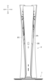
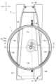
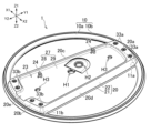
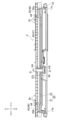
- FIG. 1 is a front view of an electronic device to which a stand device according to an embodiment of the present disclosure is attached; 2 is a bottom view of the electronic device with the stand device attached thereto; FIG. FIG. 2 is a perspective view showing the upper side of the stand device.
- FIG. 2 is a perspective view showing the lower side of the stand device.
- FIG. FIG. 4 is a perspective view showing a support member and an attachment member. 3 is a cross-sectional view of the stand device and the electronic device taken along line VV in FIG. 2.
- 6 is a cross-sectional view of the stand device and the electronic device taken along line VI-VI in FIG. 2.
- FIG. 13 is a perspective view of a stand device according to another embodiment;
- FIG. FIG. 4 is a perspective view showing the lower side of the accessory member. 2 is a cross-sectional view of the stand device and the electronic device.
- the stand device proposed in this disclosure will be described below.
- the stand device is installed on the upper surface of an immovable object that is fixed indoors (e.g., on a floor or a desk), and is capable of supporting an electronic device on the object.
- FIG. 1 is a front view of the electronic device 2 with the stand device 1 attached.
- FIG. 2 is a bottom view of the electronic device 2 with the stand device 1 attached.
- the directions indicated by Z1 and Z2 in FIG. 1 are referred to as upward and downward, respectively, and the directions indicated by Y1 and Y2 in FIG. 2 are referred to as forward and backward, respectively.
- the directions indicated by X1 and X2 in FIG. 1 are referred to as rightward and leftward, respectively.
- the electronic device 2 may be an information processing device.
- the electronic device 2 may be a game device that executes a game application, a content generation device that plays content such as video and audio (music), or a personal computer.
- the electronic device 2 may output video data generated by executing a game application to an output device (display and speaker).
- the electronic device 2 may output video or audio data acquired via a communication device or recording medium (hard disk drive or solid state drive) to an output device.
- the electronic device 2 has a device body 2A.
- the electronic device 2 may also have a right exterior panel 2B covering the right side of the device body 2A, and a left exterior panel 2C covering the left side of the device body 2A.
- the device body 2A is box-shaped and contains a circuit board, a heat dissipation device, and the like.
- the device body 2A may have a power button and a connector on its front.
- an air vent 2h may be formed on the bottom surface of the device body 2A.
- the stand device 1 may be attached to the electronic device 2 (more specifically, to the underside of the device body 2A) via a fastener 31 such as a screw.
- the stand device 1 can support the electronic device 2, for example, in the position shown in FIG. 1. Details of the stand device 1 are described below.
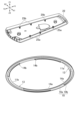
- FIG. 3A is a perspective view showing the upper side of the stand device 1.
- FIG. 3B is a perspective view showing the lower side of the stand device 1.
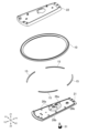
- FIG. 4A is an exploded perspective view of the stand device 1.
- FIG. 4B is a perspective view showing the lower side of a support member 10 and an attachment member 20 of the stand device 1, which will be described later.
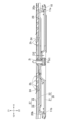
- FIG. 5 is a cross-sectional view of the stand device 1 and the electronic device 2 taken along line V-V in FIG. 2.
- FIG. 6 is a cross-sectional view of the stand device 1 and the electronic device 2 taken along line VI-VI in FIG. 2.
- the stand device 1 may have a ring-shaped support member 10 and a mounting member 20 that can be mounted to the electronic device 2 in the vertical direction (first direction).
- the support member 10 may be formed of a material that is heavier (has a higher specific gravity) than the mounting member 20.
- the support member 10 may be formed of a material that is harder than the mounting member 20.
- the mounting member 20 may be formed of a resin, and the support member 10 may be formed of a metal such as iron. In this way, the weight of the support member 10 can be ensured, and the number of parts required for the stand device 1 to support the electronic device 2 can be reduced.
- the support member 10 may be entirely formed of a metal, or may have a surface that is plated or painted. In this embodiment, the support member 10 is not covered with resin.
- the support member 10 may be annular. In this way, the support member 10 can be machined using a lathe, making it easier to form the support member 10.
- the shape of the support member 10 is not limited to this, and may be a polygonal shape such as a rectangle, or may be a shape that resembles other letters or symbols.
- the mounting member 20 may have holes H1, H2 that penetrate in the vertical direction.
- a fastener 31 may be inserted into either of these holes H1, H2.
- the fastener 31 may be inserted, for example, from the lower side of hole H1, and as shown in FIG. 5 and FIG. 6, into hole 2i formed on the lower surface of the device main body 2A. In this way, the mounting member 20 may be attached to the electronic device 2 and fixed to the electronic device 2.
- the mounting member 20 has two holes H1, H2. As shown in FIG. 2, a fastener 31 is inserted into one of the two holes H1, H2. A cap 32 for covering the hole into which the fastener 31 is not inserted may be inserted into one of the two holes H1, H2. Furthermore, the number of holes into which the fastener 31 can be inserted in the mounting member 20 is not limited to two, and may be one or three. By having two or more holes, it becomes possible for electronic devices of different shapes to be supported by the stand device 1, as described below.
- the support member 10 may have a first connection portion 11a and a second connection portion 11b to which the mounting member 20 is attached.
- the first connection portion 11a and the second connection portion 11b may be located on opposite sides of holes H1, H2 in the mounting member 20 in a direction (front-rear direction) that intersects with the up-down direction (first direction).
- first connection portion 11a and the second connection portion 11b are also simply referred to as connection portions 11a, 11b.
- the support member 10 may have a first support portion 12a and a second support portion 12b that support the stand device 1 and the electronic device 2 against an immovable body such as a floor surface.
- the first support portion 12a and the second support portion 12b may be located on opposite sides of the mounting member 20 in a direction (left-right direction, second direction) that intersects with the up-down direction (first direction).
- first support portion 12a and the second support portion 12b are also simply referred to as support portions 12a, 12b.
- the stand device 1 has a structure in which an attachment member 20 is attached to an annular support member 10. This allows the stand device 1 to be constructed with a simple structure. Also, by attaching the attachment member 20 to the support member 10 at the two connection parts 11a, 11b, the rigidity of the attachment member 20 and the support member 10 can be ensured. In this way, the support of the electronic device 2 can be stabilized.
- recesses 14a, 14b may be formed on the underside of support member 10.
- Support portions 12a, 12b may be formed by attaching anti-slip members 15 (see FIG. 4A) such as rubber to the inside of these recesses 14a, 14b.
- Anti-slip members 15 may be fixed to the inside of recess 14a with an adhesive or a sticky agent. In this way, it is possible to prevent stand device 1 from slipping against an immovable body such as a floor surface.
- the mounting member 20 may be configured to include a base member 21 and a cover member 22 shown in FIG. 4A.
- the base member 21 and the cover member 22 may be combined with each other vertically to sandwich at least one of the first connection portion 11a and the second connection portion 11b of the support member 10 shown in FIG. 4B, and may be attached to the at least one connection portion (the first connection portion 11a and/or the second connection portion 11b).
- the mounting member 20 may have an end portion (the front end portion 20a or the rear end portion 20b) that sandwiches at least one of the first connection portion 11a and the second connection portion 11b in the vertical direction (first direction).
- the at least one connection portion does not have a mounting hole such as a screw hole formed therein, as shown in FIG. 4B.
- the at least one connection portion may be formed as a surface that extends continuously over the entire area that overlaps with the mounting member 20 in a plan view. By doing this, the rigidity of the support member 10 can be ensured at that one connection part.
- the base member 21 and cover member 22 of the mounting member 20 sandwich both the first connection portion 11a and the second connection portion 11b of the support member 10 and are attached to the first connection portion 11a and the second connection portion 11b.
- the mounting member 20 has two ends (the front end 20a and the rear end 20b) that sandwich the first connection portion 11a and the second connection portion 11b in the vertical direction, respectively. In this way, it is not necessary to form mounting holes in both the connection portions 11a and 11b.
- Both the connection portions 11a and 11b may be formed with a surface that extends continuously over the entire area that overlaps with the mounting member 20 in a plan view. In this way, the rigidity of the support member 10 can be ensured in both the connection portions 11a and 11b.
- One of the first connection portion 11a and the second connection portion 11b of the support member 10 to which the mounting member 20 is attached may be formed on the inner peripheral portion 10a of the support member 10.
- the outer peripheral portion 10b of the support member 10 may be exposed from the mounting member 20 at the one connection portion (the first connection portion 11a and/or the second connection portion 11b). In this way, the outer peripheral portion 10b of the support member 10 can be made larger at the one connection portion, and the rigidity of the support member 10 can be ensured.
- both the first connection portion 11a and the second connection portion 11b of the support member 10 are formed on the inner peripheral portion 10a of the support member 10.
- the outer peripheral portion 10b of the support member 10 is exposed from the mounting member 20.
- the outer peripheral portion 10b of the support member 10 can be made larger at both connection portions 11a and 11b.
- the entire outer peripheral portion 10b of the support member 10 is exposed from the mounting member 20.
- the support member 10 may be formed so that the thickness of the outer circumferential portion 10b in the vertical direction is greater than the thickness of the inner circumferential portion 10a in the vertical direction.
- the outer circumferential portion 10b thicker in this manner, the rigidity of the support member 10 can be ensured.
- the thicker outer circumferential portion 10b since an impact from outside the support member 10 is received by the thicker outer circumferential portion 10b, it is possible to protect the thinner inner circumferential portion 10a.
- the base member 21 and the cover member 22 of the mounting member 20 may be fixed by a plurality of fasteners such as screws in a state where they are combined with each other at the top and bottom.
- the mounting member 20 may have a front end 20a and a rear end 20b, and a plurality of fasteners 33a, 33b may be inserted into these ends 20a, 20b, respectively.
- the plurality of fasteners 33a may be arranged along the inner peripheral edge of the front side of the annular support member 10.
- the plurality of fasteners 33b may be arranged along the inner peripheral edge of the rear side of the support member 10.
- the number of fasteners 33a is three and the number of fasteners 33b is four, but the number of fasteners 33a, 33b is not necessarily limited to this.
- One of the base member 21 and the cover member 22 of the mounting member 20 may have a claw portion that hooks onto the other member.
- the cover member 22 has a plurality of claw portions 25a, 25b.
- the base member 21 has a plurality of engaged portions 26a, 26b that hook onto the claw portions 25a, 25b.
- the plurality of claw portions 25a are lined up along the right edge of the cover member 22, and the plurality of claw portions 25b are lined up along the left edge of the cover member 22.
- the plurality of engaged portions 26a are lined up along the right edge of the base member 21, and the plurality of engaged portions 26b are lined up along the left edge of the base member 21.
- the plurality of claw portions 25a, 25b are formed at positions corresponding to the same number of engaged portions 26a, 26b (the same positions in the directions along the X-axis and Y-axis).
- all of the multiple claws 25a, 25b face in the same direction (rearward in the example shown in FIG. 4B). Therefore, it is possible to fit the cover member 22 to the base member 21 by sliding the cover member 22 in the direction in which the multiple claws 25a, 25b face (rearward) relative to the base member 21.
- the number of claws 25a, 25b and the number of engaged portions 26a, 26b are six, but the number of claws 25a, 25b and the number of engaged portions 26a, 26b are not necessarily limited to this.
- recesses 13a and 13b may be formed on the underside of the inner periphery 10a of the support member 10.
- the recess 13a may be located on the front side of the inner periphery 10a
- the recess 13b may be located on the rear side of the inner periphery 10a.
- the first connection portion 11a of the support member 10 to which the mounting member 20 is attached may include the front recess 13a.
- the second connection portion 11b may include the rear recess 13b.
- the base member 21 may fit into these recesses 13a and 13b. This allows the position of the base member 21 (the mounting member 20 including the base member 21) in the circumferential direction of the support member 10 to be determined. Furthermore, the mounting member 20 can be prevented from moving relative to the support member 10.
- the mounting member 20 may have a facing surface 27 facing the electronic device 2 (more specifically, the device body 2A) when attached to the electronic device 2.
- the facing surface 27 may be formed with a first surface 28 that contacts the outer surface of the electronic device 2 (more specifically, the bottom surface of the device body 2A) and a second surface 29 that ensures a gap between the first surface 28 and the outer surface of the electronic device 2 (the bottom surface of the device body 2A). In this way, the electronic device 2 comes into contact with the first surface 28, and the electronic device 2 can be supported.
- the second surface 29 forms a gap between the second surface 29 and the ventilation hole 2h formed in the electronic device 2, and an air flow path to the ventilation hole 2h (see FIG. 6) can be ensured.
- the facing surface 27 facing the electronic device 2 in the stand device 1 may be defined on the upper surface of the mounting member 20 (more specifically, the cover member 22).
- the facing surface 27 is defined on the entire upper surface of the mounting member 20.
- a part of the upper surface of the mounting member 20 may be the facing surface 27.
- a recess 23 may be formed on the upper surface (facing surface 27) of the mounting member 20, and the first surface 28 may be defined on the edge of the recess 23, and the second surface 29 may be defined on the bottom of the recess 23.
- the first surface 28 may surround the second surface 29.
- the first surface 28 may be formed along the front end 20a, the rear end 20b, the right end 20c, and the left end 20d of the mounting member 20.
- a groove 20e that connects the outside of the mounting member 20 to the inside of the recess 23 may be formed at an end (e.g., rear end 20b) of the mounting member 20.
- an air flow path can be secured from the outside of the mounting member 20 to the ventilation opening 2h (see FIG. 6) of the device body 2A.
- the groove 20e is formed at the rear end 20b of the mounting member 20, but the groove 20e may also be formed at the front end 20a, right end 20c, or left end 20d of the mounting member 20.
- the mounting member 20 may have a convex portion 24 that protrudes upward from the opposing surface 27 (e.g., a second surface 29 defined by the bottom of the recess 23).
- the mounting member 20 may have two convex portions 24. In a direction intersecting the up-down direction (e.g., the front-to-rear direction), the two convex portions 24 may be spaced apart from each other. In a direction intersecting the up-down direction (e.g., the front-to-rear direction), the hole H1 into which the fastener 31 is inserted may be disposed between the two convex portions 24.
- the number of convex portions 24 formed on the mounting member 20 may be one, or may be three or more.
- the protrusion 24 formed on the opposing surface 27 of the mounting member 20 may be inserted into the ventilation hole 2h of the electronic device 2. Furthermore, in the mounting member 20, the distance from the protrusion 24 to the hole H1 into which the fastener 31 is inserted may match or approximate the distance from the ventilation hole 2h of the electronic device 2 to the hole 2i into which the fastener 31 is inserted. In this way, the positions of the hole H1 and the hole 2i can be aligned when the protrusion 24 is inserted into the ventilation hole 2h, making it easier to attach the stand device 1 to the electrical device 2.
- the stand device 1 is configured by having the annular support member 10 with the connection parts 11a and 11b, and the mounting member 20 attached to the connection parts 11a and 11b. This allows the stand device 1 to be configured with a simple structure. Also, by attaching the mounting member 20 to the support member 10 at the two connection parts 11a and 11b, it is possible to ensure the rigidity of the mounting member 20 and the support member 10 and stabilize the support of the electronic device 2.
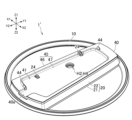
- FIG. 7 is a perspective view of a stand device 1', which is another example of an embodiment.
- the stand device 1' shown in FIG. 7 is capable of supporting an electronic device in the same manner as the stand device 1 described in the embodiment.
- the stand device 1' is capable of supporting an electronic device having a different shape from the electronic device 2 described in the embodiment.
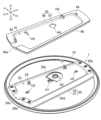
- FIG. 8 is an exploded perspective view of the stand device 1'.
- the stand device 1' may have an accessory member 40.
- the accessory member 40 may be made of resin, like the mounting member 20.
- the accessory member 40 may be attached to the upper side of the stand device 1 described in the embodiment (more specifically, to the upper surface of the mounting member 20).
- the height of the stand device 1 in the vertical direction can be increased and the position of the protrusion that fits into the ventilation hole 2h formed in the electronic device can be changed.
- an electronic device for example, the electronic device 2' shown in FIG. 10 in which the distance D1 (see FIG. 5) from the bottom surface of the device main body 2A to the bottom end of the right exterior panel 2B (or the left exterior panel 2C) is large.
- Figure 9 is a perspective view showing the underside of an accessory member 40, which is a component of the stand device 1'.
- the upper surface of the accessory member 40 may have a recess 41 that is recessed downward as shown in Figure 8, and the opposite lower surface of the accessory member 40 may have a protrusion 42 that protrudes downward as shown in Figure 9.
- the protrusion 42 of the accessory member 40 may have a shape that corresponds to the recess 23 and groove 20e of the mounting member 20.
- the accessory member 40 may also have a cylindrical protrusion 43 that protrudes downward from the protrusion 42. In this way, the accessory member 40 fits onto the upper surface of the mounting member 20, and the position of the accessory member 40 relative to the mounting member 20 can be prevented from shifting.
- FIG. 10 is a cross-sectional view of the stand device 1' and the electronic device 2'.
- the accessory member 40 like the mounting member 20, may have an opposing surface 45 that faces the electronic device 2' when attached to the electronic device 2'.
- the opposing surface 45 may be formed with a first surface 46 that contacts the outer surface (bottom surface) of the electronic device 2' and a second surface 47 that ensures a gap between the outer surface (bottom surface) of the electronic device 2'. In this way, it is possible to support the electronic device 2' on the first surface 46 and ensure an air flow path to the ventilation opening 2h.
- a groove 40e may be formed at an end (e.g., the rear end) of the accessory member 40, similar to the mounting member 20, connecting the outside of the accessory member 40 with the inside of the recess 41. In this way, an air flow path can be secured from the outside of the accessory member 40 to the ventilation opening 2h (see FIG. 10) of the device body.
- the groove 40e is formed at the rear end of the accessory member 40, but the groove 40e may also be formed at the front, right, or left end of the accessory member 40.
- the accessory member 40 has a hole H4 at the same position as the hole H2 of the mounting member 20.
- the mounting member 20 is fixed to the electronic device 2 by inserting the fixing device 31 into the hole H1 of the mounting member 20, whereas in the example shown in FIG. 10, one fixing device 31 is inserted into the hole H2 of the mounting member 20 and the hole H4 of the accessory member 40, and the mounting member 20 and the accessory member 40 are fixed to the electronic device 2'.
- the fixing device 31 is inserted from the lower side of the holes H2 and H4, and is inserted into the hole 2i formed on the lower surface of the electronic device 2'.
- the stand device 1' including the accessory member 40 it becomes possible to attach the stand device 1' including the accessory member 40 to an electronic device whose hole 2i is located at a different position from the electronic device 2.
- the accessory member 40 exposes the hole H2 of the mounting member 20 at the hole H4, but may cover the hole H1 of the mounting member 20 and block the hole H1.
- the accessory member 40 may have a convex portion 44 that protrudes upward from an opposing surface 45 (e.g., a first surface 46 defined by the edge of the recess 41) similar to the mounting member 20.
- the accessory member 40 may have two convex portions 44. In a direction intersecting the up-down direction (e.g., the front-rear direction), the two convex portions 44 may be spaced apart from each other. In a direction intersecting the up-down direction (e.g., the front-rear direction), the holes H2 and H4 into which the fastener 31 is inserted may be disposed between the two convex portions 44.
- the number of convex portions 44 formed on the accessory member 40 may be one, or may be three or more.
- the convex portion 44 formed on the opposing surface 45 of the accessory member 40 may be inserted into the ventilation hole 2h of the electronic device 2.
- the convex portion 44 of the accessory member 40 may be formed at a position different from the convex portion 24 of the mounting member 20.
- the distance from the convex portion 44 to the holes H2 and H4 into which the fastener 31 is inserted may match or approximate the distance from the ventilation hole 2h of the electronic device 2' shown in FIG. 10 to the hole 2i into which the fastener 31 is inserted. In this way, the holes H2 and H4 can be aligned with the holes 2i when the convex portion 44 is inserted into the ventilation hole 2h, making it easier to attach the stand device 1' to the electrical device 2'.
- the opposing surface 45 of the accessory member 40 may have a hole H5 at the same position as the convex portion 24 of the mounting member 20. In this way, when the accessory member 40 is attached to the mounting member 20, the convex portion 24 of the mounting member 20 can be prevented from interfering with the bottom surface of the accessory member 40. Also, the first surface 46 that contacts the outer surface (bottom surface) of the electronic device 2' may be positioned at the same position as the top of the convex portion 24 in the vertical direction, or at a higher position than the top of the convex portion 24. In this way, it is possible to prevent the convex portion 24 from interfering with the electronic device 2'. In other words, by using the accessory member 40, the position of the convex portion inserted into the hole 2i of the electronic device 2' can be changed from the position of the convex portion 24 to the position of the convex portion 44.
- the two holes H1, H2 formed in the mounting member 20 may be formed in recesses C1, C2 recessed upward from the bottom surface of the mounting member 20.
- the depth of the recess C2 in which the hole H2 is formed may be greater than the depth of the recess C1 in which the hole H1 is formed.
- the distance D2 from the lower edge of the hole H1 to the lower surface of the electronic device 2 (the distance to the first surface 28 on the facing surface 27) shown in FIG. 6 and the distance D3 from the lower edge of the hole H2 to the lower surface of the electronic device 2' (the distance to the first surface 46 on the facing surface 45) shown in FIG. 10 can be made to match or approximate each other.
- the stand device described in the present disclosure includes a ring-shaped support member and an attachment member attached to the support member and capable of being attached to an electronic device in a first direction.
- the support member includes a first connection portion and a second connection portion to which the attachment member is attached, and a first support portion and a second support portion located on opposite sides of the attachment member in a second direction intersecting the first direction.
- the mounting member may include a base member and a cover member.
- the base member and the cover member may be combined with each other in the first direction to sandwich at least one of the first and second connection portions, and may be attached to the at least one connection portion.
- the base member and the cover member may be combined with each other in a first direction to sandwich both the first connection portion and the second connection portion, and may be attached to the first connection portion and the second connection portion.
- the mounting member may have an end portion that sandwiches at least one of the first connection portion and the second connection portion in the first direction, and may be attached to the at least one connection portion by the end portion.
- the mounting member may have two ends that respectively sandwich the first connection portion and the second connection portion in the first direction, and may be attached to the first connection portion and the second connection portion by the two ends.
- At least one of the first connection portion and the second connection portion may not have a mounting hole formed therein.
- At least one of the first connection portion and the second connection portion may be formed on an inner periphery of the support member, and the outer periphery of the support member may be exposed from the mounting member at the at least one connection portion.
- the support member may be annular.
- the support member may be made of metal.
- the mounting member may have an opposing surface facing the electronic device, and the opposing surface may be formed with a surface that contacts an outer surface of the electronic device and a surface that ensures a gap between the outer surface of the electronic device and the mounting member.
Landscapes
- Engineering & Computer Science (AREA)
- General Engineering & Computer Science (AREA)
- Mechanical Engineering (AREA)
- Theoretical Computer Science (AREA)
- Human Computer Interaction (AREA)
- Physics & Mathematics (AREA)
- General Physics & Mathematics (AREA)
- Casings For Electric Apparatus (AREA)
- Devices For Indicating Variable Information By Combining Individual Elements (AREA)
Abstract
Description
(第1の方向で)電子機器2に取り付け可能な取付部材20を有してよい。支持部材10は、取付部材20よりも重い(比重の高い)材料で形成されてよい。支持部材10は、取付部材20よりも硬い材料で形成されてよい。取付部材20は樹脂で形成されてよく、支持部材10は鉄などの金属で形成されてよい。このようにすることで、支持部材10の重さを確保し、スタンド装置1が電子機器2の支持を可能にするための部品数を低減できる。支持部材10は、その全体が金属で形成されてもよいし、表面にメッキや塗装が施されたものであってもよい。本実施形態において、支持部材10は、樹脂によって覆われていない。
(1)
以上のように、本開示で説明したスタンド装置は、環状の支持部材と、前記支持部材に取り付けられており、電子機器に第1の方向で取り付け可能な取付部材と、を有している。前記支持部材は、前記取付部材が取り付けられている第1接続部及び第2接続部と、前記第1の方向に対して交差する第2の方向において前記取付部材を挟んで互いに反対側に位置している第1支持部及び第2支持部と、を有している。これによれば、簡単な構造で電子機器の支持構造を構成し、且つ電子機器の支持安定性を確保できる。
上記(1)のスタンド装置は、前記取付部材はベース部材とカバー部材とを含んでもよい。前記ベース部材と前記カバー部材は、前記第1の方向において互いに組み合わされて前記第1接続部と前記第2接続部の少なくとも一方の接続部を挟んでよく、前記少なくとも一方の接続部に取り付けられてもよい。
上記(2)のスタンド装置において、前記ベース部材と前記カバー部材は、第1の方向において互いに組み合わされて前記第1接続部と前記第2接続部の双方を挟んでよく、前記第1接続部と前記第2接続部とに取り付けられてもよい。
上記(1)~(3)のうちのいずれかのスタンド装置において、前記取付部材は、前記第1接続部と前記第2接続部の少なくとも一方の接続部を前記第1の方向において挟む端部を有してよく、前記端部によって前記少なくとも一方の接続部に取り付けられてもよい。
上記(4)のスタンド装置において、前記取付部材は、前記第1接続部と前記第2接続部とを前記第1の方向においてそれぞれ挟む2つの端部を有してもよく、前記2つの端部によって前記第1接続部と前記第2接続部とに取り付けられてもよい。
上記(1)~(5)のうちのいずれかのスタンド装置において、前記第1接続部と前記第2接続部の少なくとも一方の接続部には、取り付け用の穴が形成されていなくてもよい。
上記(1)~(6)のうちのいずれかのスタンド装置において、前記第1接続部と前記第2接続部の少なくとも一方の接続部は、前記支持部材の内周部に形成されてもよく、前記支持部材の外周部は、前記少なくとも一方の接続部において、前記取付部材から露出してもよい。
上記(1)~(7)のうちのいずれかのスタンド装置において、前記支持部材は円環状であってもよい。
上記(1)~(8)のうちのいずれかのスタンド装置において、前記支持部材は金属で形成されてもよい。
上記(1)~(9)のうちのいずれかのスタンド装置において、前記取付部材は、前記電子機器に向く対向面を有してもよく、前記対向面には、前記電子機器の外面に接する面と、前記電子機器の外面との間に隙間を確保する面とが形成されてもよい。
Claims (10)
- 環状の支持部材と、
前記支持部材に取り付けられており、電子機器に第1の方向で取り付け可能な取付部材と、を有し、
前記支持部材は、
前記取付部材が取り付けられている第1接続部及び第2接続部と、
前記第1の方向に対して交差する第2の方向において前記取付部材を挟んで互いに反対側に位置している第1支持部及び第2支持部と、を有している
電子機器のスタンド装置。 - 前記取付部材はベース部材とカバー部材とを含み、
前記ベース部材と前記カバー部材は、前記第1の方向において互いに組み合わされて前記第1接続部と前記第2接続部の少なくとも一方の接続部を挟み、前記少なくとも一方の接続部に取り付けられている
請求項1に記載されるスタンド装置。 - 前記ベース部材と前記カバー部材は、第1の方向において互いに組み合わされて前記第1接続部と前記第2接続部の双方を挟み、前記第1接続部と前記第2接続部とに取り付けられている
請求項2に記載されるスタンド装置。 - 前記取付部材は、前記第1接続部と前記第2接続部の少なくとも一方の接続部を前記第1の方向において挟む端部を有し、前記端部によって前記少なくとも一方の接続部に取り付けられている
請求項1に記載されるスタンド装置。 - 前記取付部材は、前記第1接続部と前記第2接続部とを前記第1の方向においてそれぞれ挟む2つの端部を有し、前記2つの端部によって前記第1接続部と前記第2接続部とに取り付けられている
請求項4に記載されるスタンド装置。 - 前記第1接続部と前記第2接続部の少なくとも一方の接続部には、取り付け用の穴が形成されていない
請求項1に記載されるスタンド装置。 - 前記第1接続部と前記第2接続部の少なくとも一方の接続部は、前記支持部材の内周部に形成されており、
前記支持部材の外周部は、前記少なくとも一方の接続部において、前記取付部材から露出している
請求項1に記載される電子機器のスタンド。 - 前記支持部材は円環状である
請求項1に記載されるスタンド装置。 - 前記支持部材は金属で形成されている
請求項1に記載されるスタンド装置。 - 前記取付部材は、前記電子機器に向く対向面を有し、
前記対向面には、前記電子機器の外面に接する面と、前記電子機器の外面との間に隙間を確保する面とが形成されている
請求項1に記載されるスタンド装置。
Priority Applications (3)
| Application Number | Priority Date | Filing Date | Title |
|---|---|---|---|
| EP24788658.3A EP4697129A4 (en) | 2023-04-11 | 2024-04-04 | SUPPORT DEVICE |
| CN202480024455.9A CN120898188A (zh) | 2023-04-11 | 2024-04-04 | 支架设备 |
| JP2025513928A JPWO2024214633A1 (ja) | 2023-04-11 | 2024-04-04 |
Applications Claiming Priority (2)
| Application Number | Priority Date | Filing Date | Title |
|---|---|---|---|
| JP2023064457 | 2023-04-11 | ||
| JP2023-064457 | 2023-04-11 |
Publications (1)
| Publication Number | Publication Date |
|---|---|
| WO2024214633A1 true WO2024214633A1 (ja) | 2024-10-17 |
Family
ID=93059193
Family Applications (1)
| Application Number | Title | Priority Date | Filing Date |
|---|---|---|---|
| PCT/JP2024/013971 Ceased WO2024214633A1 (ja) | 2023-04-11 | 2024-04-04 | スタンド装置 |
Country Status (4)
| Country | Link |
|---|---|
| EP (1) | EP4697129A4 (ja) |
| JP (1) | JPWO2024214633A1 (ja) |
| CN (1) | CN120898188A (ja) |
| WO (1) | WO2024214633A1 (ja) |
Citations (2)
| Publication number | Priority date | Publication date | Assignee | Title |
|---|---|---|---|---|
| WO2013154041A1 (ja) | 2012-04-13 | 2013-10-17 | 株式会社ソニー・コンピュータエンタテインメント | 電子機器 |
| WO2021014664A1 (ja) * | 2019-07-19 | 2021-01-28 | パナソニックIpマネジメント株式会社 | 電子機器及びスタンド |
Family Cites Families (1)
| Publication number | Priority date | Publication date | Assignee | Title |
|---|---|---|---|---|
| JP4148972B2 (ja) * | 2006-07-10 | 2008-09-10 | 三菱電機株式会社 | 回転台及び表示装置 |
-
2024
- 2024-04-04 EP EP24788658.3A patent/EP4697129A4/en active Pending
- 2024-04-04 WO PCT/JP2024/013971 patent/WO2024214633A1/ja not_active Ceased
- 2024-04-04 CN CN202480024455.9A patent/CN120898188A/zh active Pending
- 2024-04-04 JP JP2025513928A patent/JPWO2024214633A1/ja active Pending
Patent Citations (2)
| Publication number | Priority date | Publication date | Assignee | Title |
|---|---|---|---|---|
| WO2013154041A1 (ja) | 2012-04-13 | 2013-10-17 | 株式会社ソニー・コンピュータエンタテインメント | 電子機器 |
| WO2021014664A1 (ja) * | 2019-07-19 | 2021-01-28 | パナソニックIpマネジメント株式会社 | 電子機器及びスタンド |
Non-Patent Citations (1)
| Title |
|---|
| See also references of EP4697129A1 |
Also Published As
| Publication number | Publication date |
|---|---|
| CN120898188A (zh) | 2025-11-04 |
| JPWO2024214633A1 (ja) | 2024-10-17 |
| EP4697129A4 (en) | 2026-07-15 |
| EP4697129A1 (en) | 2026-02-18 |
Similar Documents
| Publication | Publication Date | Title |
|---|---|---|
| JP7712479B2 (ja) | 耐侵入性携帯型スピーカ | |
| CN115316049B (zh) | 用于电子设备的支架和电子设备组件 | |
| JP2018022752A (ja) | 電子機器 | |
| JP2010287796A (ja) | 電子機器 | |
| JP2009043106A (ja) | 電子機器 | |
| JP5801848B2 (ja) | 電子機器用スタンド | |
| JP5050110B2 (ja) | 電子機器 | |
| EP4697129A1 (en) | Stand device | |
| JP4427301B2 (ja) | ノート型のポータブルコンピュータ | |
| EP3932501B1 (en) | Game controller | |
| WO2006106827A1 (ja) | ケース体および電気機器 | |
| EP4672877A1 (en) | ELECTRONIC DEVICE ASSEMBLY, ELECTRONIC DEVICE AND SUPPORT | |
| JP6721853B1 (ja) | 電子機器 | |
| JP7789535B2 (ja) | 表示装置 | |
| JP3601980B2 (ja) | 電子機器 | |
| JP2008276519A (ja) | 電子機器 | |
| JP4891980B2 (ja) | 電子機器 | |
| JP3128411U (ja) | ファン取り付け構造 | |
| KR200410470Y1 (ko) | 포터블 데스크톱 컴퓨터 | |
| JP2005306093A (ja) | 車載機器 | |
| JP5863743B2 (ja) | 情報処理装置 | |
| JP2007208090A (ja) | 電子機器のエスカション取付構造 | |
| JP2008028155A (ja) | プリント基板の実装構造 | |
| JP2020053659A (ja) | ケーブル保持部材および電子機器 | |
| JP2008095853A (ja) | 筐体シャーシ |
Legal Events
| Date | Code | Title | Description |
|---|---|---|---|
| 121 | Ep: the epo has been informed by wipo that ep was designated in this application |
Ref document number: 24788658 Country of ref document: EP Kind code of ref document: A1 |
|
| ENP | Entry into the national phase |
Ref document number: 2025513928 Country of ref document: JP Kind code of ref document: A |
|
| WWE | Wipo information: entry into national phase |
Ref document number: 2025513928 Country of ref document: JP |
|
| WWE | Wipo information: entry into national phase |
Ref document number: 202480024455.9 Country of ref document: CN |
|
| WWP | Wipo information: published in national office |
Ref document number: 202480024455.9 Country of ref document: CN |
|
| WWE | Wipo information: entry into national phase |
Ref document number: 2024788658 Country of ref document: EP |
|
| NENP | Non-entry into the national phase |
Ref country code: DE |
|
| ENP | Entry into the national phase |
Ref document number: 2024788658 Country of ref document: EP Effective date: 20251111 |
|
| ENP | Entry into the national phase |
Ref document number: 2024788658 Country of ref document: EP Effective date: 20251111 |
|
| ENP | Entry into the national phase |
Ref document number: 2024788658 Country of ref document: EP Effective date: 20251111 |
|
| ENP | Entry into the national phase |
Ref document number: 2024788658 Country of ref document: EP Effective date: 20251111 |
|
| ENP | Entry into the national phase |
Ref document number: 2024788658 Country of ref document: EP Effective date: 20251111 |
|
| ENP | Entry into the national phase |
Ref document number: 2024788658 Country of ref document: EP Effective date: 20251111 |
|
| ENP | Entry into the national phase |
Ref document number: 2024788658 Country of ref document: EP Effective date: 20251111 |
|
| ENP | Entry into the national phase |
Ref document number: 2024788658 Country of ref document: EP Effective date: 20251111 |
|
| ENP | Entry into the national phase |
Ref document number: 2024788658 Country of ref document: EP Effective date: 20251111 |
|
| WWP | Wipo information: published in national office |
Ref document number: 2024788658 Country of ref document: EP |