WO2024214818A1 - 方向性電磁鋼板および絶縁被膜の形成方法 - Google Patents
方向性電磁鋼板および絶縁被膜の形成方法 Download PDFInfo
- Publication number
- WO2024214818A1 WO2024214818A1 PCT/JP2024/014841 JP2024014841W WO2024214818A1 WO 2024214818 A1 WO2024214818 A1 WO 2024214818A1 JP 2024014841 W JP2024014841 W JP 2024014841W WO 2024214818 A1 WO2024214818 A1 WO 2024214818A1
- Authority
- WO
- WIPO (PCT)
- Prior art keywords
- steel sheet
- grain
- ion concentration
- coating
- oriented electrical
- Prior art date
- Legal status (The legal status is an assumption and is not a legal conclusion. Google has not performed a legal analysis and makes no representation as to the accuracy of the status listed.)
- Ceased
Links
Images


Classifications
-
- C—CHEMISTRY; METALLURGY
- C23—COATING METALLIC MATERIAL; COATING MATERIAL WITH METALLIC MATERIAL; CHEMICAL SURFACE TREATMENT; DIFFUSION TREATMENT OF METALLIC MATERIAL; COATING BY VACUUM EVAPORATION, BY SPUTTERING, BY ION IMPLANTATION OR BY CHEMICAL VAPOUR DEPOSITION, IN GENERAL; INHIBITING CORROSION OF METALLIC MATERIAL OR INCRUSTATION IN GENERAL
- C23C—COATING METALLIC MATERIAL; COATING MATERIAL WITH METALLIC MATERIAL; SURFACE TREATMENT OF METALLIC MATERIAL BY DIFFUSION INTO THE SURFACE, BY CHEMICAL CONVERSION OR SUBSTITUTION; COATING BY VACUUM EVAPORATION, BY SPUTTERING, BY ION IMPLANTATION OR BY CHEMICAL VAPOUR DEPOSITION, IN GENERAL
- C23C22/00—Chemical surface treatment of metallic material by reaction of the surface with a reactive liquid, leaving reaction products of surface material in the coating, e.g. conversion coatings, passivation of metals
- C23C22/05—Chemical surface treatment of metallic material by reaction of the surface with a reactive liquid, leaving reaction products of surface material in the coating, e.g. conversion coatings, passivation of metals using aqueous solutions
- C23C22/06—Chemical surface treatment of metallic material by reaction of the surface with a reactive liquid, leaving reaction products of surface material in the coating, e.g. conversion coatings, passivation of metals using aqueous solutions using aqueous acidic solutions with pH less than 6
- C23C22/07—Chemical surface treatment of metallic material by reaction of the surface with a reactive liquid, leaving reaction products of surface material in the coating, e.g. conversion coatings, passivation of metals using aqueous solutions using aqueous acidic solutions with pH less than 6 containing phosphates
- C23C22/08—Orthophosphates
-
- C—CHEMISTRY; METALLURGY
- C21—METALLURGY OF IRON
- C21D—MODIFYING THE PHYSICAL STRUCTURE OF FERROUS METALS; GENERAL DEVICES FOR HEAT TREATMENT OF FERROUS OR NON-FERROUS METALS OR ALLOYS; MAKING METAL MALLEABLE, e.g. BY DECARBURISATION OR TEMPERING
- C21D8/00—Modifying the physical properties of ferrous metals or ferrous alloys by deformation combined with, or followed by, heat treatment
- C21D8/12—Modifying the physical properties of ferrous metals or ferrous alloys by deformation combined with, or followed by, heat treatment during manufacturing of articles with special electromagnetic properties
-
- C—CHEMISTRY; METALLURGY
- C21—METALLURGY OF IRON
- C21D—MODIFYING THE PHYSICAL STRUCTURE OF FERROUS METALS; GENERAL DEVICES FOR HEAT TREATMENT OF FERROUS OR NON-FERROUS METALS OR ALLOYS; MAKING METAL MALLEABLE, e.g. BY DECARBURISATION OR TEMPERING
- C21D8/00—Modifying the physical properties of ferrous metals or ferrous alloys by deformation combined with, or followed by, heat treatment
- C21D8/12—Modifying the physical properties of ferrous metals or ferrous alloys by deformation combined with, or followed by, heat treatment during manufacturing of articles with special electromagnetic properties
- C21D8/1244—Modifying the physical properties of ferrous metals or ferrous alloys by deformation combined with, or followed by, heat treatment during manufacturing of articles with special electromagnetic properties characterised by the heat treatment
- C21D8/1272—Final recrystallisation annealing
-
- C—CHEMISTRY; METALLURGY
- C21—METALLURGY OF IRON
- C21D—MODIFYING THE PHYSICAL STRUCTURE OF FERROUS METALS; GENERAL DEVICES FOR HEAT TREATMENT OF FERROUS OR NON-FERROUS METALS OR ALLOYS; MAKING METAL MALLEABLE, e.g. BY DECARBURISATION OR TEMPERING
- C21D8/00—Modifying the physical properties of ferrous metals or ferrous alloys by deformation combined with, or followed by, heat treatment
- C21D8/12—Modifying the physical properties of ferrous metals or ferrous alloys by deformation combined with, or followed by, heat treatment during manufacturing of articles with special electromagnetic properties
- C21D8/1277—Modifying the physical properties of ferrous metals or ferrous alloys by deformation combined with, or followed by, heat treatment during manufacturing of articles with special electromagnetic properties involving a particular surface treatment
- C21D8/1283—Application of a separating or insulating coating
-
- C—CHEMISTRY; METALLURGY
- C21—METALLURGY OF IRON
- C21D—MODIFYING THE PHYSICAL STRUCTURE OF FERROUS METALS; GENERAL DEVICES FOR HEAT TREATMENT OF FERROUS OR NON-FERROUS METALS OR ALLOYS; MAKING METAL MALLEABLE, e.g. BY DECARBURISATION OR TEMPERING
- C21D8/00—Modifying the physical properties of ferrous metals or ferrous alloys by deformation combined with, or followed by, heat treatment
- C21D8/12—Modifying the physical properties of ferrous metals or ferrous alloys by deformation combined with, or followed by, heat treatment during manufacturing of articles with special electromagnetic properties
- C21D8/1277—Modifying the physical properties of ferrous metals or ferrous alloys by deformation combined with, or followed by, heat treatment during manufacturing of articles with special electromagnetic properties involving a particular surface treatment
- C21D8/1288—Application of a tension-inducing coating
-
- C—CHEMISTRY; METALLURGY
- C21—METALLURGY OF IRON
- C21D—MODIFYING THE PHYSICAL STRUCTURE OF FERROUS METALS; GENERAL DEVICES FOR HEAT TREATMENT OF FERROUS OR NON-FERROUS METALS OR ALLOYS; MAKING METAL MALLEABLE, e.g. BY DECARBURISATION OR TEMPERING
- C21D8/00—Modifying the physical properties of ferrous metals or ferrous alloys by deformation combined with, or followed by, heat treatment
- C21D8/12—Modifying the physical properties of ferrous metals or ferrous alloys by deformation combined with, or followed by, heat treatment during manufacturing of articles with special electromagnetic properties
- C21D8/1294—Modifying the physical properties of ferrous metals or ferrous alloys by deformation combined with, or followed by, heat treatment during manufacturing of articles with special electromagnetic properties involving a localised treatment
-
- C—CHEMISTRY; METALLURGY
- C21—METALLURGY OF IRON
- C21D—MODIFYING THE PHYSICAL STRUCTURE OF FERROUS METALS; GENERAL DEVICES FOR HEAT TREATMENT OF FERROUS OR NON-FERROUS METALS OR ALLOYS; MAKING METAL MALLEABLE, e.g. BY DECARBURISATION OR TEMPERING
- C21D9/00—Heat treatment, e.g. annealing, hardening, quenching or tempering, adapted for particular articles; Furnaces therefor
- C21D9/46—Heat treatment, e.g. annealing, hardening, quenching or tempering, adapted for particular articles; Furnaces therefor for sheet metals
-
- C—CHEMISTRY; METALLURGY
- C22—METALLURGY; FERROUS OR NON-FERROUS ALLOYS; TREATMENT OF ALLOYS OR NON-FERROUS METALS
- C22C—ALLOYS
- C22C38/00—Ferrous alloys, e.g. steel alloys
- C22C38/004—Very low carbon steels, i.e. having a carbon content of less than 0,01%
-
- C—CHEMISTRY; METALLURGY
- C22—METALLURGY; FERROUS OR NON-FERROUS ALLOYS; TREATMENT OF ALLOYS OR NON-FERROUS METALS
- C22C—ALLOYS
- C22C38/00—Ferrous alloys, e.g. steel alloys
- C22C38/008—Ferrous alloys, e.g. steel alloys containing tin
-
- C—CHEMISTRY; METALLURGY
- C22—METALLURGY; FERROUS OR NON-FERROUS ALLOYS; TREATMENT OF ALLOYS OR NON-FERROUS METALS
- C22C—ALLOYS
- C22C38/00—Ferrous alloys, e.g. steel alloys
- C22C38/02—Ferrous alloys, e.g. steel alloys containing silicon
-
- C—CHEMISTRY; METALLURGY
- C22—METALLURGY; FERROUS OR NON-FERROUS ALLOYS; TREATMENT OF ALLOYS OR NON-FERROUS METALS
- C22C—ALLOYS
- C22C38/00—Ferrous alloys, e.g. steel alloys
- C22C38/04—Ferrous alloys, e.g. steel alloys containing manganese
-
- C—CHEMISTRY; METALLURGY
- C22—METALLURGY; FERROUS OR NON-FERROUS ALLOYS; TREATMENT OF ALLOYS OR NON-FERROUS METALS
- C22C—ALLOYS
- C22C38/00—Ferrous alloys, e.g. steel alloys
- C22C38/16—Ferrous alloys, e.g. steel alloys containing copper
-
- C—CHEMISTRY; METALLURGY
- C22—METALLURGY; FERROUS OR NON-FERROUS ALLOYS; TREATMENT OF ALLOYS OR NON-FERROUS METALS
- C22C—ALLOYS
- C22C38/00—Ferrous alloys, e.g. steel alloys
- C22C38/60—Ferrous alloys, e.g. steel alloys containing lead, selenium, tellurium, or antimony, or more than 0.04% by weight of sulfur
-
- C—CHEMISTRY; METALLURGY
- C23—COATING METALLIC MATERIAL; COATING MATERIAL WITH METALLIC MATERIAL; CHEMICAL SURFACE TREATMENT; DIFFUSION TREATMENT OF METALLIC MATERIAL; COATING BY VACUUM EVAPORATION, BY SPUTTERING, BY ION IMPLANTATION OR BY CHEMICAL VAPOUR DEPOSITION, IN GENERAL; INHIBITING CORROSION OF METALLIC MATERIAL OR INCRUSTATION IN GENERAL
- C23C—COATING METALLIC MATERIAL; COATING MATERIAL WITH METALLIC MATERIAL; SURFACE TREATMENT OF METALLIC MATERIAL BY DIFFUSION INTO THE SURFACE, BY CHEMICAL CONVERSION OR SUBSTITUTION; COATING BY VACUUM EVAPORATION, BY SPUTTERING, BY ION IMPLANTATION OR BY CHEMICAL VAPOUR DEPOSITION, IN GENERAL
- C23C22/00—Chemical surface treatment of metallic material by reaction of the surface with a reactive liquid, leaving reaction products of surface material in the coating, e.g. conversion coatings, passivation of metals
-
- C—CHEMISTRY; METALLURGY
- C23—COATING METALLIC MATERIAL; COATING MATERIAL WITH METALLIC MATERIAL; CHEMICAL SURFACE TREATMENT; DIFFUSION TREATMENT OF METALLIC MATERIAL; COATING BY VACUUM EVAPORATION, BY SPUTTERING, BY ION IMPLANTATION OR BY CHEMICAL VAPOUR DEPOSITION, IN GENERAL; INHIBITING CORROSION OF METALLIC MATERIAL OR INCRUSTATION IN GENERAL
- C23C—COATING METALLIC MATERIAL; COATING MATERIAL WITH METALLIC MATERIAL; SURFACE TREATMENT OF METALLIC MATERIAL BY DIFFUSION INTO THE SURFACE, BY CHEMICAL CONVERSION OR SUBSTITUTION; COATING BY VACUUM EVAPORATION, BY SPUTTERING, BY ION IMPLANTATION OR BY CHEMICAL VAPOUR DEPOSITION, IN GENERAL
- C23C22/00—Chemical surface treatment of metallic material by reaction of the surface with a reactive liquid, leaving reaction products of surface material in the coating, e.g. conversion coatings, passivation of metals
- C23C22/05—Chemical surface treatment of metallic material by reaction of the surface with a reactive liquid, leaving reaction products of surface material in the coating, e.g. conversion coatings, passivation of metals using aqueous solutions
- C23C22/06—Chemical surface treatment of metallic material by reaction of the surface with a reactive liquid, leaving reaction products of surface material in the coating, e.g. conversion coatings, passivation of metals using aqueous solutions using aqueous acidic solutions with pH less than 6
- C23C22/07—Chemical surface treatment of metallic material by reaction of the surface with a reactive liquid, leaving reaction products of surface material in the coating, e.g. conversion coatings, passivation of metals using aqueous solutions using aqueous acidic solutions with pH less than 6 containing phosphates
- C23C22/08—Orthophosphates
- C23C22/20—Orthophosphates containing aluminium cations
-
- C—CHEMISTRY; METALLURGY
- C23—COATING METALLIC MATERIAL; COATING MATERIAL WITH METALLIC MATERIAL; CHEMICAL SURFACE TREATMENT; DIFFUSION TREATMENT OF METALLIC MATERIAL; COATING BY VACUUM EVAPORATION, BY SPUTTERING, BY ION IMPLANTATION OR BY CHEMICAL VAPOUR DEPOSITION, IN GENERAL; INHIBITING CORROSION OF METALLIC MATERIAL OR INCRUSTATION IN GENERAL
- C23C—COATING METALLIC MATERIAL; COATING MATERIAL WITH METALLIC MATERIAL; SURFACE TREATMENT OF METALLIC MATERIAL BY DIFFUSION INTO THE SURFACE, BY CHEMICAL CONVERSION OR SUBSTITUTION; COATING BY VACUUM EVAPORATION, BY SPUTTERING, BY ION IMPLANTATION OR BY CHEMICAL VAPOUR DEPOSITION, IN GENERAL
- C23C22/00—Chemical surface treatment of metallic material by reaction of the surface with a reactive liquid, leaving reaction products of surface material in the coating, e.g. conversion coatings, passivation of metals
- C23C22/05—Chemical surface treatment of metallic material by reaction of the surface with a reactive liquid, leaving reaction products of surface material in the coating, e.g. conversion coatings, passivation of metals using aqueous solutions
- C23C22/06—Chemical surface treatment of metallic material by reaction of the surface with a reactive liquid, leaving reaction products of surface material in the coating, e.g. conversion coatings, passivation of metals using aqueous solutions using aqueous acidic solutions with pH less than 6
- C23C22/07—Chemical surface treatment of metallic material by reaction of the surface with a reactive liquid, leaving reaction products of surface material in the coating, e.g. conversion coatings, passivation of metals using aqueous solutions using aqueous acidic solutions with pH less than 6 containing phosphates
- C23C22/08—Orthophosphates
- C23C22/22—Orthophosphates containing alkaline earth metal cations
-
- C—CHEMISTRY; METALLURGY
- C23—COATING METALLIC MATERIAL; COATING MATERIAL WITH METALLIC MATERIAL; CHEMICAL SURFACE TREATMENT; DIFFUSION TREATMENT OF METALLIC MATERIAL; COATING BY VACUUM EVAPORATION, BY SPUTTERING, BY ION IMPLANTATION OR BY CHEMICAL VAPOUR DEPOSITION, IN GENERAL; INHIBITING CORROSION OF METALLIC MATERIAL OR INCRUSTATION IN GENERAL
- C23C—COATING METALLIC MATERIAL; COATING MATERIAL WITH METALLIC MATERIAL; SURFACE TREATMENT OF METALLIC MATERIAL BY DIFFUSION INTO THE SURFACE, BY CHEMICAL CONVERSION OR SUBSTITUTION; COATING BY VACUUM EVAPORATION, BY SPUTTERING, BY ION IMPLANTATION OR BY CHEMICAL VAPOUR DEPOSITION, IN GENERAL
- C23C22/00—Chemical surface treatment of metallic material by reaction of the surface with a reactive liquid, leaving reaction products of surface material in the coating, e.g. conversion coatings, passivation of metals
- C23C22/05—Chemical surface treatment of metallic material by reaction of the surface with a reactive liquid, leaving reaction products of surface material in the coating, e.g. conversion coatings, passivation of metals using aqueous solutions
- C23C22/06—Chemical surface treatment of metallic material by reaction of the surface with a reactive liquid, leaving reaction products of surface material in the coating, e.g. conversion coatings, passivation of metals using aqueous solutions using aqueous acidic solutions with pH less than 6
- C23C22/24—Chemical surface treatment of metallic material by reaction of the surface with a reactive liquid, leaving reaction products of surface material in the coating, e.g. conversion coatings, passivation of metals using aqueous solutions using aqueous acidic solutions with pH less than 6 containing hexavalent chromium compounds
- C23C22/33—Chemical surface treatment of metallic material by reaction of the surface with a reactive liquid, leaving reaction products of surface material in the coating, e.g. conversion coatings, passivation of metals using aqueous solutions using aqueous acidic solutions with pH less than 6 containing hexavalent chromium compounds containing also phosphates
-
- C—CHEMISTRY; METALLURGY
- C23—COATING METALLIC MATERIAL; COATING MATERIAL WITH METALLIC MATERIAL; CHEMICAL SURFACE TREATMENT; DIFFUSION TREATMENT OF METALLIC MATERIAL; COATING BY VACUUM EVAPORATION, BY SPUTTERING, BY ION IMPLANTATION OR BY CHEMICAL VAPOUR DEPOSITION, IN GENERAL; INHIBITING CORROSION OF METALLIC MATERIAL OR INCRUSTATION IN GENERAL
- C23C—COATING METALLIC MATERIAL; COATING MATERIAL WITH METALLIC MATERIAL; SURFACE TREATMENT OF METALLIC MATERIAL BY DIFFUSION INTO THE SURFACE, BY CHEMICAL CONVERSION OR SUBSTITUTION; COATING BY VACUUM EVAPORATION, BY SPUTTERING, BY ION IMPLANTATION OR BY CHEMICAL VAPOUR DEPOSITION, IN GENERAL
- C23C22/00—Chemical surface treatment of metallic material by reaction of the surface with a reactive liquid, leaving reaction products of surface material in the coating, e.g. conversion coatings, passivation of metals
- C23C22/73—Chemical surface treatment of metallic material by reaction of the surface with a reactive liquid, leaving reaction products of surface material in the coating, e.g. conversion coatings, passivation of metals characterised by the process
- C23C22/74—Chemical surface treatment of metallic material by reaction of the surface with a reactive liquid, leaving reaction products of surface material in the coating, e.g. conversion coatings, passivation of metals characterised by the process for obtaining burned-in conversion coatings
-
- C—CHEMISTRY; METALLURGY
- C23—COATING METALLIC MATERIAL; COATING MATERIAL WITH METALLIC MATERIAL; CHEMICAL SURFACE TREATMENT; DIFFUSION TREATMENT OF METALLIC MATERIAL; COATING BY VACUUM EVAPORATION, BY SPUTTERING, BY ION IMPLANTATION OR BY CHEMICAL VAPOUR DEPOSITION, IN GENERAL; INHIBITING CORROSION OF METALLIC MATERIAL OR INCRUSTATION IN GENERAL
- C23C—COATING METALLIC MATERIAL; COATING MATERIAL WITH METALLIC MATERIAL; SURFACE TREATMENT OF METALLIC MATERIAL BY DIFFUSION INTO THE SURFACE, BY CHEMICAL CONVERSION OR SUBSTITUTION; COATING BY VACUUM EVAPORATION, BY SPUTTERING, BY ION IMPLANTATION OR BY CHEMICAL VAPOUR DEPOSITION, IN GENERAL
- C23C22/00—Chemical surface treatment of metallic material by reaction of the surface with a reactive liquid, leaving reaction products of surface material in the coating, e.g. conversion coatings, passivation of metals
- C23C22/78—Pretreatment of the material to be coated
-
- C—CHEMISTRY; METALLURGY
- C23—COATING METALLIC MATERIAL; COATING MATERIAL WITH METALLIC MATERIAL; CHEMICAL SURFACE TREATMENT; DIFFUSION TREATMENT OF METALLIC MATERIAL; COATING BY VACUUM EVAPORATION, BY SPUTTERING, BY ION IMPLANTATION OR BY CHEMICAL VAPOUR DEPOSITION, IN GENERAL; INHIBITING CORROSION OF METALLIC MATERIAL OR INCRUSTATION IN GENERAL
- C23C—COATING METALLIC MATERIAL; COATING MATERIAL WITH METALLIC MATERIAL; SURFACE TREATMENT OF METALLIC MATERIAL BY DIFFUSION INTO THE SURFACE, BY CHEMICAL CONVERSION OR SUBSTITUTION; COATING BY VACUUM EVAPORATION, BY SPUTTERING, BY ION IMPLANTATION OR BY CHEMICAL VAPOUR DEPOSITION, IN GENERAL
- C23C22/00—Chemical surface treatment of metallic material by reaction of the surface with a reactive liquid, leaving reaction products of surface material in the coating, e.g. conversion coatings, passivation of metals
- C23C22/82—After-treatment
-
- C—CHEMISTRY; METALLURGY
- C23—COATING METALLIC MATERIAL; COATING MATERIAL WITH METALLIC MATERIAL; CHEMICAL SURFACE TREATMENT; DIFFUSION TREATMENT OF METALLIC MATERIAL; COATING BY VACUUM EVAPORATION, BY SPUTTERING, BY ION IMPLANTATION OR BY CHEMICAL VAPOUR DEPOSITION, IN GENERAL; INHIBITING CORROSION OF METALLIC MATERIAL OR INCRUSTATION IN GENERAL
- C23G—CLEANING OR DE-GREASING OF METALLIC MATERIAL BY CHEMICAL METHODS OTHER THAN ELECTROLYSIS
- C23G1/00—Cleaning or pickling metallic material with solutions or molten salts
- C23G1/02—Cleaning or pickling metallic material with solutions or molten salts with acid solutions
- C23G1/08—Iron or steel
-
- C—CHEMISTRY; METALLURGY
- C23—COATING METALLIC MATERIAL; COATING MATERIAL WITH METALLIC MATERIAL; CHEMICAL SURFACE TREATMENT; DIFFUSION TREATMENT OF METALLIC MATERIAL; COATING BY VACUUM EVAPORATION, BY SPUTTERING, BY ION IMPLANTATION OR BY CHEMICAL VAPOUR DEPOSITION, IN GENERAL; INHIBITING CORROSION OF METALLIC MATERIAL OR INCRUSTATION IN GENERAL
- C23G—CLEANING OR DE-GREASING OF METALLIC MATERIAL BY CHEMICAL METHODS OTHER THAN ELECTROLYSIS
- C23G1/00—Cleaning or pickling metallic material with solutions or molten salts
- C23G1/02—Cleaning or pickling metallic material with solutions or molten salts with acid solutions
- C23G1/08—Iron or steel
- C23G1/083—Iron or steel solutions containing H3PO4
-
- H—ELECTRICITY
- H01—ELECTRIC ELEMENTS
- H01F—MAGNETS; INDUCTANCES; TRANSFORMERS; SELECTION OF MATERIALS FOR THEIR MAGNETIC PROPERTIES
- H01F1/00—Magnets or magnetic bodies characterised by the magnetic materials therefor; Selection of materials for their magnetic properties
- H01F1/01—Magnets or magnetic bodies characterised by the magnetic materials therefor; Selection of materials for their magnetic properties of inorganic materials
- H01F1/03—Magnets or magnetic bodies characterised by the magnetic materials therefor; Selection of materials for their magnetic properties of inorganic materials characterised by their coercivity
- H01F1/12—Magnets or magnetic bodies characterised by the magnetic materials therefor; Selection of materials for their magnetic properties of inorganic materials characterised by their coercivity of soft-magnetic materials
- H01F1/14—Magnets or magnetic bodies characterised by the magnetic materials therefor; Selection of materials for their magnetic properties of inorganic materials characterised by their coercivity of soft-magnetic materials metals or alloys
- H01F1/147—Alloys characterised by their composition
- H01F1/14766—Fe-Si based alloys
- H01F1/14775—Fe-Si based alloys in the form of sheets
- H01F1/14783—Fe-Si based alloys in the form of sheets with insulating coating
-
- H—ELECTRICITY
- H01—ELECTRIC ELEMENTS
- H01F—MAGNETS; INDUCTANCES; TRANSFORMERS; SELECTION OF MATERIALS FOR THEIR MAGNETIC PROPERTIES
- H01F1/00—Magnets or magnetic bodies characterised by the magnetic materials therefor; Selection of materials for their magnetic properties
- H01F1/01—Magnets or magnetic bodies characterised by the magnetic materials therefor; Selection of materials for their magnetic properties of inorganic materials
- H01F1/03—Magnets or magnetic bodies characterised by the magnetic materials therefor; Selection of materials for their magnetic properties of inorganic materials characterised by their coercivity
- H01F1/12—Magnets or magnetic bodies characterised by the magnetic materials therefor; Selection of materials for their magnetic properties of inorganic materials characterised by their coercivity of soft-magnetic materials
- H01F1/14—Magnets or magnetic bodies characterised by the magnetic materials therefor; Selection of materials for their magnetic properties of inorganic materials characterised by their coercivity of soft-magnetic materials metals or alloys
- H01F1/16—Magnets or magnetic bodies characterised by the magnetic materials therefor; Selection of materials for their magnetic properties of inorganic materials characterised by their coercivity of soft-magnetic materials metals or alloys in the form of sheets
- H01F1/18—Magnets or magnetic bodies characterised by the magnetic materials therefor; Selection of materials for their magnetic properties of inorganic materials characterised by their coercivity of soft-magnetic materials metals or alloys in the form of sheets with insulating coating
-
- C—CHEMISTRY; METALLURGY
- C21—METALLURGY OF IRON
- C21D—MODIFYING THE PHYSICAL STRUCTURE OF FERROUS METALS; GENERAL DEVICES FOR HEAT TREATMENT OF FERROUS OR NON-FERROUS METALS OR ALLOYS; MAKING METAL MALLEABLE, e.g. BY DECARBURISATION OR TEMPERING
- C21D2201/00—Treatment for obtaining particular effects
- C21D2201/05—Grain orientation
Definitions
- the present invention relates to a grain-oriented electrical steel sheet and a method for forming an insulating coating.
- Grain-oriented electrical steel sheets are primarily used in transformers. Transformers are continuously excited over a long period of time, from installation to disposal, and continue to generate energy loss. For this reason, the energy loss that occurs when magnetized with alternating current, i.e., iron loss, is the primary indicator that determines the performance of a transformer.
- a forsterite-based coating with excellent coating adhesion is produced during the finish annealing process of electrical steel sheets by a reaction between oxides on the surface of the steel sheet and an annealing separator, and is a coating that can apply tension to steel sheets.
- the method disclosed in Patent Document 1 in which a coating liquid mainly composed of colloidal silica and phosphate is baked onto the surface of a steel sheet to form an insulating coating, is an effective method for reducing iron loss because it is highly effective in applying tension to the steel sheet. Therefore, the general method for manufacturing grain-oriented electrical steel sheets is to leave the forsterite-based coating formed in the final annealing process and apply an insulating coating mainly composed of phosphate on top of it.
- Patent Document 2 discloses a technique for preventing the formation of inorganic coatings, in which the steel sheet surface is made mirror-finished by chemical polishing or electrolytic polishing after pickling to remove surface deposits following normal finish annealing. It has been found that an even more excellent iron loss improvement effect can be obtained by forming a tensioned insulating coating on the surface of an inorganic coating-free oriented electrical steel sheet obtained by such a known method. Furthermore, in addition to improving iron loss, tensioned insulating coatings can also impart various other properties such as corrosion resistance, heat resistance, and slipperiness.
- inorganic coatings not only have the effect of providing insulation, but also have the effect of serving as an intermediate layer that ensures adhesion when forming a tension coating (tension-applying insulating coating).
- inorganic coatings are formed in a state in which they penetrate deeply into the steel sheet, and therefore have excellent adhesion to the metal steel sheet. Therefore, when a tension-applying coating (tension coating) whose main components are colloidal silica or phosphate is formed on the surface of an inorganic coating, the coating has excellent adhesion.
- Patent Document 3 discloses a technique in which a grain-oriented electrical steel sheet having no inorganic coating is annealed in a weakly reducing atmosphere to selectively thermally oxidize silicon inevitably contained in the silicon steel sheet, thereby forming an SiO2 layer on the steel sheet surface, and then a tension-imparting insulating coating is formed.
- Patent Document 4 discloses a technique in which a grain-oriented electrical steel sheet having no inorganic coating is anodically electrolyzed in a silicate aqueous solution to form an SiO2 layer on the steel sheet surface, and then a tension-imparting insulating coating is formed.
- Patent Document 3 requires preparation of an annealing facility capable of controlling the atmosphere in order to perform annealing in a weakly reducing atmosphere, which causes a problem in terms of processing costs.
- annealing facility capable of controlling the atmosphere in order to perform annealing in a weakly reducing atmosphere, which causes a problem in terms of processing costs.
- Patent Document 4 in order to obtain a SiO 2 layer on the steel sheet surface that maintains sufficient adhesion to the tension-imparting insulating coating by performing anodizing in a silicate aqueous solution, it is necessary to prepare a new electrolytic processing facility, which causes a problem in terms of processing costs.
- Patent Document 5 discloses a grain-oriented electrical steel sheet having a base steel sheet and an insulating coating formed on the surface of the base steel sheet, the insulating coating being formed on the base steel sheet side, an intermediate layer containing a crystalline metal phosphate, and a tensile coating layer formed on the surface side of the insulating coating.
- the intermediate layer can be formed by chemical conversion treatment.
- Patent Document 6 relates to a method for producing a grain-oriented silicon steel sheet, and discloses a method in which, prior to the formation of a tension-imparting insulating coating, a coating mainly made of zinc phosphate is formed on a grain-oriented silicon steel sheet that has been subjected to secondary recrystallization in an amount of 0.1 g/ m2 or more and 10 g/ m2 or less per side of the steel sheet.
- the present invention aims to provide a method for forming a grain-oriented electrical steel sheet and insulating coating that has excellent adhesion and magnetic properties of the tensile coating and does not reduce the space factor of the transformer (core).
- the inventors discovered that when providing a layer containing a metal phosphate as an intermediate layer to improve adhesion between the base steel sheet and the tensile coating layer, the interface between the intermediate layer and the base material can be smoothed by adjusting the ratio of metal ions, phosphate ions, and nitrate ions in the chemical conversion treatment solution within a specific range, resulting in a grain-oriented electrical steel sheet that has excellent adhesion and magnetic properties of the tensile coating and does not reduce the space factor of the transformer (core).
- the present invention was made in consideration of the above findings.
- the gist of one aspect of the present invention is as follows.
- a grain-oriented electrical steel sheet comprises a base steel sheet, An insulating coating formed on a surface of the base steel sheet; having The insulating coating is An intermediate layer formed on the base steel sheet side and containing a crystalline metal phosphate; a tensile coating layer formed on a surface side of the insulating coating, When the interface between the base steel plate and the intermediate layer is observed at 5000 times magnification by a scanning electron microscope in a cross section along the thickness direction of the intermediate layer, the ratio of the interface length L to the observed image width W is 100.0 to 120.0%.
- the tensile coating layer may contain a metal phosphate and silica.
- a method for forming an insulating coating according to one aspect of the present invention is a method for forming the insulating coating provided on the grain-oriented electrical steel sheet according to the above-mentioned [1], comprising the steps of: a finish annealing process in which an annealing separator containing 10 to 100 mass% of Al 2 O 3 is applied to a steel sheet, the steel sheet is dried, and then finish annealing is performed; an annealing separator removing step of removing excess annealing separator from the steel sheet after the finish annealing step; a pickling process in which the steel sheet after the annealing separator removal process is pickled with 0.1 to 5 mass % of one inorganic acid selected from sulfuric acid, chloric acid, nitric acid, and phosphoric acid for 1 to 20 seconds; an immersion step of immersing the steel sheet after the pickling step in a treatment solution containing a metal phosphate, an oxidizing agent, and iron ions; a drying step of
- the steel sheet after the pickling step may be immersed in the treatment liquid having a liquid temperature of 20 to 85° C. for 2 to 60 seconds.
- the nitrate ion concentration may be 2.0 to 25.0 g/L.
- a directional electromagnetic steel sheet and a method for forming an insulating coating that have excellent adhesion and magnetic properties of the tensile coating and do not reduce the space factor of the transformer (core).
- FIG. 1 is an example of a cross-sectional view of a grain-oriented electrical steel sheet according to an embodiment of the present invention.
- FIG. 11 is a schematic diagram for explaining a method for determining a concavo-convex index according to the present embodiment.
- a grain-oriented electrical steel sheet according to one embodiment of the present invention (grain-oriented electrical steel sheet according to this embodiment) and a method for manufacturing the grain-oriented electrical steel sheet according to this embodiment, including a method for forming the insulating coating provided on the grain-oriented electrical steel sheet according to this embodiment, will be described.
- the grain-oriented electrical steel sheet according to this embodiment will be described.
- the grain-oriented electrical steel sheet 100 has a base steel sheet 1 and an insulating coating 2 formed on the surface of the base steel sheet 1.
- the grain-oriented electrical steel sheet 100 according to this embodiment does not substantially have a forsterite-based coating on the surface of the base steel sheet 1.
- a forsterite-based coating is not intentionally formed on the surface of the base steel sheet 1, but the presence of a forsterite-based coating is permitted as long as the coating amount of the forsterite-based coating is 1 g/ m2 or less (in that case, it is present in a part between the base steel sheet 1 and the insulating coating 2).
- the grain-oriented electrical steel sheet 100 according to this embodiment may have a forsterite-based coating of 0 to 1 g/ m2 on the surface of the base steel sheet 1.
- the insulating coating 2 has a tensile coating layer 22 formed on the surface side of the insulating coating 2 (i.e., the surface side of the directional electromagnetic steel sheet 100) and an intermediate layer 21 formed on the base steel sheet 1 side and containing a crystalline metal phosphate.
- the ratio of the interface length L to the observed image width W (irregularity index) of the intermediate layer 21 is 100 to 120%.
- the grain-oriented electrical steel sheet 100 is significantly characterized by the structure of the insulating coating 2 formed on the surface of the base steel sheet 1, and the base steel sheet 1 included in the grain-oriented electrical steel sheet 100 is not limited in terms of its chemical composition. However, in order to obtain the characteristics generally required of a grain-oriented electrical steel sheet, it is preferable that the chemical components contain the following: In this embodiment, % relating to the chemical components is % by mass unless otherwise specified.
- C 0.010% or less
- C (carbon) is an element effective for controlling the structure of the steel sheet in the process up to the completion of the decarburization annealing process in the manufacturing process.
- the C content is preferably 0.010% or less.
- the C content is more preferably 0.005% or less. The lower the C content, the more preferable it is, but even if the C content is reduced to less than 0.0001%, the effect of grain control is saturated and the manufacturing cost is only increased. Therefore, the C content may be 0.0001% or more.
- Si 2.50-4.00%
- Silicon (Si) is an element that increases the electrical resistance of grain-oriented electrical steel sheets and improves their core loss characteristics. If the Si content is less than 2.50%, a sufficient effect of reducing eddy current loss cannot be obtained. Therefore, the Si content is preferably 2.50% or more, more preferably 2.70% or more, and further preferably 3.00% or more. On the other hand, if the Si content exceeds 4.00%, the grain-oriented electrical steel sheet becomes embrittled and the sheet passing property is significantly deteriorated. In addition, the workability of the grain-oriented electrical steel sheet is deteriorated, and the steel sheet is likely to break during rolling. For this reason, the Si content is preferably 4.00% or less, more preferably 3.80% or less, and further preferably 3.70% or less.
- Mn 0.01-0.50%
- Mn manganese
- Mn is an element that combines with S to form MnS during the manufacturing process. This precipitate acts as an inhibitor (a suppressor of normal grain growth) and suppresses secondary recrystallization in steel.
- Mn is an element that also improves the hot workability of steel. If the Mn content is less than 0.01%, the above effects cannot be sufficiently obtained. Therefore, the Mn content is preferably 0.01% or more, and more preferably 0.02% or more. On the other hand, if the Mn content exceeds 0.50%, secondary recrystallization does not occur, and the magnetic properties of the steel deteriorate.
- the Mn content is preferably 0.50% or less, more preferably 0.20% or less, and further preferably 0.10% or less.
- N 0.010% or less
- N nitrogen
- the N content is preferably 0.010% or less.
- the N content is more preferably 0.008% or less.
- the lower limit of the N content is not particularly specified, but reducing the N content to less than 0.001% would only increase the manufacturing cost, and therefore the N content may be set to 0.001% or more.
- Sol. Al 0.020% or less
- Sol. Al (acid-soluble aluminum) is an element that combines with N to form AlN, which functions as an inhibitor, during the manufacturing process of the grain-oriented electrical steel sheet.
- the sol. Al content is preferably 0.020% or less.
- the sol. Al content is more preferably 0.010% or less, and further preferably less than 0.001%.
- the lower limit of the sol. Al content is not particularly specified, but even if it is reduced to less than 0.0001%, the manufacturing cost will only increase. Therefore, the sol. Al content may be 0.0001% or more.
- S 0.010% or less
- S (sulfur) is an element that combines with Mn in the manufacturing process to form MnS, which functions as an inhibitor.
- the S content is preferably 0.010% or less. It is more preferable that the S content in the grain-oriented electrical steel sheet is as low as possible. For example, it is less than 0.001%. However, even if the S content in the grain-oriented electrical steel sheet is reduced to less than 0.0001%, the manufacturing cost will only increase. Therefore, the S content in the grain-oriented electrical steel sheet may be 0.0001% or more.
- the chemical composition of the base steel sheet of the grain-oriented electrical steel sheet according to this embodiment may contain the above-mentioned elements, with the balance being Fe and impurities.
- Sn, Cu, Se, and Sb may also be contained in the ranges shown below.
- W, Nb, Ti, Ni, Co, V, Cr, and Mo are contained in a total of 1.0% or less, this does not impair the effect of the grain-oriented electrical steel sheet according to this embodiment.
- impurities refer to elements that are mixed in from raw materials such as ore, scrap, or the manufacturing environment when the base steel sheet is industrially manufactured, and are permissible to be contained in amounts that do not adversely affect the function of the grain-oriented electrical steel sheet according to this embodiment.
- Sn 0-0.50%
- Sn (tin) is an element that contributes to improving magnetic properties through controlling the primary crystal structure.
- the Sn content is preferably 0.01% or more.
- Sn Content is more preferably 0.02% or more, and further preferably 0.03% or more.
- the Sn content is preferably 0.50% or less.
- the amount is more preferably 0.30% or less, and further preferably 0.10% or less.
- Cu 0-0.50%
- Cu (copper) is an element that contributes to an increase in the Goss orientation occupancy rate in the secondary recrystallized structure.
- the Cu content is 0.01% or more.
- the amount is more preferably 0.02% or more, and further preferably 0.03% or more.
- the Cu content exceeds 0.50%, the steel sheet becomes embrittled during hot rolling.
- the Cu content is preferably 50% or less, more preferably 0.30% or less, and further preferably 0.10% or less.
- Se is an element that has a magnetic property improving effect.
- Se content is 0.001% or more in order to effectively exhibit the magnetic property improving effect.
- Se The content is more preferably 0.003% or more, and further preferably 0.006% or more.
- the Se content is preferably 0.020% or less.
- the Se content is more preferably 0.015% or less. % or less, and more preferably 0.010% or less.
- Sb 0-0.50%
- Sb (antimony) is an element that has a magnetic property improving effect.
- the Sb content is preferably 0.005% or more in order to effectively exhibit the magnetic property improving effect.
- the content is more preferably 0.01% or more, and further preferably 0.02% or more.
- the Sb content is preferably 0.50% or less.
- the Sb content is more preferably 0. .30% or less, and more preferably 0.10% or less.
- the chemical composition of the base steel sheet of the grain-oriented electrical steel sheet contains the above-mentioned elements, with the remainder being Fe and impurities.
- the chemical composition of the base steel sheet of the grain-oriented electrical steel sheet according to this embodiment can be measured using the known ICP atomic emission spectroscopy.
- an insulating coating is formed on the surface, it must be peeled off before measurement.
- the peeling method involves immersing the sheet in a high-concentration alkaline solution (e.g., a 30% sodium hydroxide solution heated to 85°C) for 20 minutes or more, which can result in the coating being peeled off. Peeling can be determined visually. In the case of small samples, the coating may also be peeled off by surface grinding.
- the grain-oriented electrical steel sheet 100 has an insulating coating 2 formed on the surface of a base steel sheet 1 .
- the insulating coating 2 has a structure in which an intermediate layer 21 and a tensile coating layer 22 are laminated in this order from the base steel sheet 1 side.
- grain-oriented electrical steel sheets generally have a forsterite-based coating formed in the final annealing process and an insulating coating (tensile insulating coating) formed thereon.
- a forsterite-based coating hinders the movement of domain walls and has a negative effect on iron loss, and thus grain-oriented electrical steel sheets without a forsterite-based coating have been studied in order to further improve magnetic properties.
- an intermediate layer 21 containing crystalline metal phosphate is formed between the base steel sheet 1 and the tensile coating layer 2, thereby improving the adhesion between the base steel sheet 1 and the tensile coating layer 22 via the intermediate layer 21.
- the intermediate layer 21 contains crystalline metal phosphate
- the tensile coating formed thereon (which becomes the tensile coating layer 22 after formation) also contains metal phosphate, resulting in high affinity and excellent adhesion between the intermediate layer and the tensile coating layer.
- the intermediate layer 1 when the intermediate layer 1 is formed by immersing in a treatment liquid containing metal phosphate, as described below, it can be formed on the surface of the base steel sheet 1 by utilizing a chemical reaction, and adhesion between the intermediate layer 21 and the base steel sheet 1 can also be ensured.
- the intermediate layer 21 does not contain a crystalline metal phosphate, the above-mentioned effect cannot be obtained.
- the ratio of the crystalline metal phosphate in the intermediate layer 21 is preferably 80 mass % or more, and may be 100 mass %. In terms of adhesion, it is preferable to use one of zinc phosphate, manganese phosphate, zinc calcium phosphate, and iron manganese phosphate as the metal phosphate.
- the intermediate layer 21 may contain oxides and elements such as Fe and Si diffused from the base steel sheet 1 as the remainder of the metal phosphate.
- the cause of the deterioration of the magnetic properties is that when the intermediate layer is formed, i.e., during chemical conversion treatment, the surface of the base steel sheet is etched at the same time as the phosphate crystals are precipitated, forming an uneven structure at the interface between the base steel sheet and the intermediate layer, which results in the obstruction of the flow of magnetic flux through the base steel sheet.
- the unevenness index also affects the space factor.
- the unevenness index increases because the chemical conversion treatment liquid used to form the intermediate layer etches the surface of the steel sheet, but at the same time, the fine unevenness on the surface side of the intermediate layer 21 also increases. As a result, the fine unevenness of the tensile coating layer 22 formed above the intermediate layer 21 also increases, resulting in a decrease in the space factor.
- the degree of unevenness (irregularity level) at the interface between the base steel sheet 1 and the intermediate layer 21 is reduced, thereby ensuring good adhesion and space factor while suppressing deterioration of the magnetic properties.
- L/W which is the ratio of the interface length L to the observed image width W (irregularity index)
- FIG. 2 is a schematic diagram for explaining how to determine the unevenness index L/W, and is a schematic cross-sectional diagram taken along the thickness direction of the intermediate layer 21.
- the cross section is observed at 5000 times magnification by SEM to obtain an observation image including the interface between the base steel sheet 1 and the intermediate layer 21.
- the distance between two points of the interface between the base steel sheet 1 and the intermediate layer 21 in the observation image is set as the observation image width W
- the actual interface path i.e., the curved path tracing the actual interface
- the interface length L the unevenness index L/W (%) is obtained.
- This unevenness index L/W is an index of the degree of unevenness of the interface, and it can be said that the smaller the unevenness index L/W, the smaller the degree of unevenness and the better the smoothing of the interface.
- the degree of unevenness observed changes depending on the observation magnification by SEM. Therefore, the observation magnification by SEM is set to a range suitable for observing the interface, and is set to 5000 times in this embodiment.
- the cross section from which the observation image for measuring the unevenness index L/W is obtained is selected from a flat portion on the surface of the grain-oriented electrical steel sheet that has no surface defects or fine processing, and when calculating the unevenness index L/W, the average value of the numerical values measured from the observation images at three points is used.
- the observed image width W and interface length L can be easily determined by using an application system such as "LUZEX AP" manufactured by Nireco Corporation for cross-sectional images taken with an electron microscope.
- the unevenness index L/W is 100.0 to 120.0%. If the unevenness index L/W exceeds 120.0%, the degree of unevenness at the interface increases, and there is a risk of the magnetic properties deteriorating. Therefore, the unevenness index is 120.0% or less. It is preferably less than 120.0%, more preferably 118.0% or less, even more preferably 115.0% or less, and even more preferably 110.0% or less.
- the lower limit of the unevenness index L/W is 100.0%. When the unevenness index L/W is 100.0%, the observed image width W and the interface length L are the same, that is, the degree of unevenness is zero and the interface is smooth.
- the thickness of the intermediate layer 21 is preferably 1.0 to 9.0 ⁇ m. If the average thickness of the intermediate layer 21 is less than 1.0 ⁇ m, the effect of improving the adhesion between the base steel sheet 1 and the insulating coating 2 via the intermediate layer 21 may not be sufficiently obtained. On the other hand, if the average thickness of the intermediate layer 21 exceeds 9.0 ⁇ m, the magnetic properties may deteriorate.
- the thickness of the intermediate layer 21 can be determined by the following method.
- the thickness of the intermediate layer 21 can be obtained by measurement using a scanning electron microscope (SEM) and an energy dispersive elemental analyzer. That is, a sample consisting of the base steel sheet 1 and the insulating coating layer 2 is cut, and the polished cross section is observed with a scanning electron microscope at 5000 times magnification to measure the thickness of the insulating coating layer 2.
- the thickness of the intermediate layer 21 can be obtained by calculation using the energy dispersive elemental analyzer, with the portion of the insulating coating layer 2 that contains Si being the tensile coating layer 22 and the portion that does not contain Si being the intermediate layer 21. Measurements are made at five or more points, and the average is taken as the thickness of the intermediate layer 21.
- the intermediate layer 21 is formed at a different time from the tensile coating layer 22 formed on top of it, but both the intermediate layer 21 and the tensile coating layer 22 function as the insulating coating 2.
- the mass proportion of the crystalline metal phosphate in the intermediate layer 21 and the type of the metal phosphate can be determined by measuring a cross section along the thickness direction of the intermediate layer 21 using a scanning electron microscope (SEM) and an energy dispersive elemental analyzer. Whether the metal phosphate in the intermediate layer 21 is a crystalline metal phosphate can be determined by X-ray crystal structure analysis.
- the base steel plate 1 and the insulating coating 2 can be distinguished by the presence or absence of phosphorus.
- the intermediate layer 21 and the tensile coating layer 22 can be distinguished by the presence or absence of silicon.
- a tensile coating is formed on the surface of the intermediate layer 21 , so that a tensile coating layer 22 is provided on the surface side of the insulating coating 2 .
- the tensile coating layer 22 is not particularly limited as long as it is used as an insulating coating for a grain-oriented electrical steel sheet, but it preferably contains a metal phosphate from the viewpoint of adhesion to the intermediate layer 21 (adhesion to the base steel sheet 1 via the intermediate layer 21).
- the tensile coating layer 22 has a composition mainly composed of aluminum phosphate and silica.
- the tensile coating layer 22 preferably contains metal phosphate and silica (derived from colloidal silica in the coating liquid) so that the silica content is 20.0% by mass or more.
- metal phosphate and silica derived from colloidal silica in the coating liquid
- the silica content of the tensile coating layer 22 exceeds 60.0% by mass, it may cause powdering, so it is preferably 60.0% by mass or less. It is also preferable that the total content of metal phosphate and silica is 70.0% by mass or more.
- the remainder other than the metal phosphate and silica may include ceramic particles such as alumina and silicon nitride.
- the metal phosphate aluminum phosphate is preferable from the viewpoint of heat resistance.
- the thickness of the tensile coating layer 22 is not limited, but the average thickness of the insulating coating 2 (intermediate layer 21 + tensile coating layer 22) is preferably 2.0 to 20.0 ⁇ m when the average thickness of the intermediate layer 21 is in the above range. If the average thickness of the insulating coating 2 is less than 2.0 ⁇ m, sufficient coating tension cannot be obtained. Also, there is a large amount of phosphoric acid eluted. In this case, it may cause stickiness and reduced corrosion resistance, and may even cause the coating to peel off. Also, if the thickness of the insulating coating 2 exceeds 20.0 ⁇ m, the space factor may decrease and the magnetic properties may deteriorate, or cracks may occur, causing reduced adhesion and reduced corrosion resistance.
- the mass proportion of the metal phosphate and the type of the metal phosphate can be determined in a cross section along the thickness direction in the same manner as in the intermediate layer 21.
- the tensile coating layer 22 and the intermediate layer 21 can be distinguished by their different silica contents.
- the thickness of the tensile coating layer 22 can be determined in the same manner as the intermediate layer 21.
- the sum of the thickness of the tensile coating layer 22 and the thickness of the intermediate layer 21 is the thickness of the insulating coating 2.
- the grain-oriented electrical steel sheet according to the present embodiment can be suitably manufactured by a manufacturing method that satisfies the manufacturing conditions described below.
- the grain-oriented electrical steel sheet according to the present embodiment is not limited to a particular manufacturing method.
- the grain-oriented electrical steel sheet having the above-mentioned configuration is considered to be the grain-oriented electrical steel sheet according to the present embodiment, regardless of its manufacturing conditions.
- the grain-oriented electrical steel sheet according to this embodiment can be manufactured by a manufacturing method including the following steps.
- IV a decarburization annealing step of performing decarburization annealing on the steel sheet after the cold rolling step;
- the treatment liquid in the immersion step satisfies the following conditions.
- metal ion concentration 1.0 to 10.0 g/L
- Phosphate ion concentration 2.0 to 25.0 g/L
- C a nitrate ion concentration of 2.0 to 40.0 g/L
- D an iron ion concentration of 1.0 to 20.0 g/L
- E the ratio of the phosphate ion concentration to the metal ion concentration is 1.5 to 5.0
- the ratio of the nitrate ion concentration to the phosphate ion concentration is 0.5 to 10.0.
- the method for producing the grain-oriented electrical steel sheet according to this embodiment further includes the steps of: (XII) a nitriding process for performing a nitriding process on the steel sheet between the decarburization annealing process and the finish annealing process; (XIII) a magnetic domain refining step for controlling magnetic domains of the steel sheet after the tensile coating layer forming step; may include either or both of the following:
- the manufacturing process of the grain-oriented electrical steel sheet according to this embodiment is characterized by the steps (V) finish annealing step to (XI) tensile coating layer forming step (which may be collectively referred to as the insulating coating forming step), which are mainly related to the formation of the insulating coating, and publicly known conditions can be adopted for the other steps or conditions not described. These steps will be described below.
- a steel billet such as a slab having a predetermined chemical composition is heated and then hot rolled to obtain a hot-rolled sheet.
- the heating temperature of the steel billet is preferably within a range of 1100 to 1450°C.
- the heating temperature is more preferably 1300 to 1400°C.
- the chemical composition of the steel billet may be changed depending on the chemical composition of the grain-oriented electrical steel sheet that is ultimately desired, but an example of a chemical composition that may be used is, in mass %, C: 0.01-0.20%, Si: 2.50-4.00%, sol. Al: 0.01-0.040%, Mn: 0.01-0.50%, N: 0.020% or less, S: 0.005-0.040%, Cu: 0-0.50%, Sn: 0-0.50%, Se: 0-0.020%, Sb: 0-0.50%, and the balance being Fe and impurities.
- Hot rolling conditions are not particularly limited and may be set appropriately based on the desired characteristics.
- the thickness of the hot rolled sheet is preferably within the range of 2.0 mm to 3.0 mm, for example.
- the hot-rolled sheet annealing process is a process of annealing the hot-rolled sheet manufactured through the hot rolling process. By carrying out such an annealing treatment, recrystallization occurs in the steel sheet structure, and it is possible to realize good magnetic properties, which is preferable.
- the hot-rolled sheet produced through a hot rolling process may be annealed according to a known method.
- the means for heating the hot-rolled sheet during annealing is not particularly limited, and any known heating method may be used.
- the annealing conditions are not particularly limited.
- the hot-rolled sheet may be annealed in a temperature range of 900 to 1200°C for 10 seconds to 5 minutes.
- Cold rolling process In the cold rolling process, the hot rolled sheet after the hot rolled sheet annealing process is subjected to cold rolling to obtain a steel sheet (cold rolled sheet).
- the cold rolling may be a single cold rolling (a series of cold rolling without annealing in between), or may be a multiple cold rolling with intermediate annealing between them, in which the cold rolling is interrupted and at least one or two or more intermediate annealings are performed before the final pass of the cold rolling process.
- intermediate annealing When intermediate annealing is performed, it is preferable to hold the steel sheet at a temperature of 1000 to 1200° C. for 5 to 180 seconds.
- the annealing atmosphere is not particularly limited. In consideration of the manufacturing cost, it is preferable to perform intermediate annealing three times or less. Furthermore, the surface of the hot-rolled sheet may be subjected to pickling before the cold rolling step.
- the hot rolled sheet after the hot rolled sheet annealing step may be cold rolled to obtain a steel sheet according to a known method.
- the final rolling reduction may be in the range of 80 to 95%. If the final rolling reduction is 80% or more, it is preferable because Goss nuclei having a high concentration of ⁇ 110 ⁇ 001> orientation in the rolling direction can be obtained. On the other hand, if the final rolling reduction exceeds 95%, it is not preferable because the secondary recrystallization is likely to become unstable in the subsequent finish annealing step.
- the final rolling reduction is the cumulative rolling reduction of cold rolling, and in the case where intermediate annealing is performed, it is the cumulative rolling reduction of cold rolling after final intermediate annealing.
- the obtained steel sheet is subjected to decarburization annealing.
- the conditions of the decarburization annealing are not limited as long as the steel sheet is subjected to primary recrystallization and C, which adversely affects magnetic properties, can be removed from the steel sheet.
- the oxidation degree (PH 2 O/PH 2 ) in the annealing atmosphere (furnace atmosphere) is set to 0.3 to 0.6
- the annealing temperature is set to 800 to 900° C. and held for 10 to 600 seconds.
- a nitriding treatment may be carried out between the decarburization annealing step and the finish annealing step described below.
- the steel sheet after the decarburization annealing process is maintained at about 700 to 850°C in a nitriding atmosphere (an atmosphere containing a gas having nitriding ability such as hydrogen, nitrogen, and ammonia) to perform the nitriding process.
- a nitriding atmosphere an atmosphere containing a gas having nitriding ability such as hydrogen, nitrogen, and ammonia
- AlN is used as an inhibitor, it is preferable that the N content of the steel sheet after the nitriding process is 40 ppm or more by the nitriding process.
- the N content of the steel sheet after the nitriding process exceeds 1000 ppm, excessive AlN is present in the steel sheet even after the completion of secondary recrystallization in the finish annealing. Such AlN causes iron loss deterioration. For this reason, it is preferable that the N content of the steel sheet after the nitriding process is 1000 ppm or less.
- annealing separator containing 10 to 100 mass% of Al 2 O 3 is applied to the steel sheet after the decarburization annealing process or after the nitriding process (after the nitriding process), dried, and then final annealing is performed.
- a forsterite-based coating is formed on the surface of a steel sheet (cold-rolled sheet) by applying an annealing separator mainly composed of MgO and then performing finish annealing.
- an annealing separator containing Al 2 O 3 is used so that a forsterite-based coating is hardly formed.
- the proportion of Al 2 O 3 may be 100% by mass, but in order to prevent Al 2 O 3 from seizing onto the steel sheet surface, in the manufacturing method of the grain-oriented electrical steel sheet according to the present embodiment, it is preferable that the annealing separator contains MgO. Although MgO may be 0%, in order to obtain the above effect, it is preferable that the proportion of MgO is 5% by mass or more. In the case where MgO is contained, the proportion of MgO is 90% by mass or less in order to ensure 10% by mass or more of Al 2 O 3. The proportion of MgO is preferably 50% by mass or less.
- the annealing separator may further contain chloride.
- the annealing separator contains chloride, the effect of making it more difficult for a forsterite-based coating to form is obtained.
- the chloride content is not particularly limited and may be 0%, but when obtaining the above effect, 0.5 to 10 mass% is preferable.
- chlorides that are effective include bismuth chloride, calcium chloride, cobalt chloride, iron chloride, and nickel chloride.
- annealing separator removal process In the annealing separator removing step, excess annealing separator is removed from the steel sheet after the final annealing step.
- the excess annealing separator can be removed by washing with water.
- the steel sheet after the annealing separator removal process is pickled for 1 to 20 seconds with one inorganic acid selected from sulfuric acid, phosphoric acid, nitric acid, and chloric acid, at 0.1 to 10 mass %, and heated to 30 to 85° C.
- one inorganic acid selected from sulfuric acid, phosphoric acid, nitric acid, and chloric acid, at 0.1 to 10 mass %, and heated to 30 to 85° C.
- the treatment solution is adjusted to satisfy the following conditions (A) to (F).
- the treatment solution contains a metal phosphate and nitric acid as an oxidizing agent.
- the metal phosphate include zinc phosphate, manganese phosphate, zinc calcium phosphate, and iron manganese phosphate. From the viewpoint of controllability of the unevenness index, zinc phosphate is preferred.
- the metal ion concentration and phosphate ion concentration in the treatment solution are 1.0 to 10.0 g/L and 2.0 to 25.0 g/L, respectively.
- the metal ion concentration and phosphate ion concentration are 1.0 g/L or more and 2.0 g/L or more, respectively.
- the metal ion concentration and the phosphate ion concentration are 10.0 g/L or less and 25.0 g/L or less, respectively.
- nitric acid is added as an oxidizing agent to the treatment liquid according to the present embodiment.
- nitric acid as an oxidizing agent, hydrogen gas generation can be prevented and a dense intermediate layer can be efficiently formed.
- the nitrate ion concentration is preferably 40.0 g/L or less.
- the acid ion concentration is preferably 2.0 g/L or more.
- the ratio of the phosphate ion concentration to the metal ion concentration is set to 1.5 to 5.0. If the ratio of the phosphate ion concentration to the metal ion concentration is too large, etching may proceed, causing the steel sheet to become excessively uneven, resulting in poor space factor.
- the ratio of the phosphate ion concentration to the metal ion concentration is set to 5.0 or less.
- the ratio of the phosphate ion concentration to the metal ion concentration is set to 1.5 or more.
- Ratio of nitrate ion concentration to phosphate ion concentration 0.5 to 10.0
- the ratio of the nitrate ion concentration to the phosphate ion concentration is also adjusted. Specifically, the ratio of the nitrate ion concentration to the phosphate ion concentration (nitrate ion concentration/phosphate ion concentration) is set to 0.5 to 10.0. If the ratio of the nitrate ion concentration to the phosphate ion concentration is too large, the etching of the steel sheet may be excessive. Therefore, the ratio of the nitrate ion concentration to the phosphate ion concentration is preferably set to 10.0 or less.
- the ratio of the nitrate ion concentration to the phosphate ion concentration is preferably set to 0.5 or more.
- the temperature of the treatment liquid is preferably 20 to 85°C, and the immersion time is preferably 5 to 150 seconds. If the liquid temperature is below 20°C or the treatment time is less than 5 seconds, the intermediate layer may not be sufficiently formed, resulting in poor adhesion. On the other hand, if the liquid temperature is above 85°C or the treatment time is more than 150 seconds, there may be areas in the intermediate layer where the crystalline metal phosphate is partially and excessively precipitated, resulting in poor space factor.
- the drying temperature is preferably 300°C or less. More preferably, it is 200°C or less.
- the drying temperature is preferably 100°C or more.
- a coating liquid containing metal phosphate and colloidal silica and having a concentration of 10 to 40 mass % is applied to the steel sheet after the drying process, dried, and then heated until the sheet temperature reaches 1000° C. By holding the temperature at 700 to 950° C. for 10 to 50 seconds, a tensile coating layer is formed on the surface of the intermediate layer.
- the sheet temperature during holding is below 700°C, the tension will be low and the magnetic properties will be inferior. Therefore, it is preferable to keep the sheet temperature at 700°C or higher.
- the sheet temperature exceeds 950°C, the rigidity of the steel sheet will decrease and it will become more susceptible to deformation. In this case, the steel sheet may become distorted due to transportation, etc., resulting in inferior magnetic properties. Therefore, it is preferable to keep the sheet temperature at 950°C or lower.
- the retention time should be 10 seconds or more.
- the retention time is more than 50 seconds, the adhesion of the tensile coating layer may be poor. Therefore, a retention time of 50 seconds or less is preferable.
- the coating liquid (insulating coating solution) is adjusted so that it contains a total of 10 to 40 mass % of metal phosphate and colloidal silica in terms of solid content. If the total concentration of the metal phosphate and colloidal silica is less than 10% by mass, the applied treatment liquid may flow easily, resulting in uneven application. If the total concentration of the metal phosphate and colloidal silica is more than 40% by mass, the viscosity may be too high, resulting in uneven patterns or application.
- metal phosphate for example, one or a mixture of two or more selected from aluminum phosphate, zinc phosphate, magnesium phosphate, nickel phosphate, copper phosphate, lithium phosphate, cobalt phosphate, etc. can be used. Among these, aluminum phosphate is preferred.
- the coating liquid may contain additional elements such as vanadium, tungsten, molybdenum, zirconium, etc. When these elements are contained, they can be added to the coating liquid, for example, as an oxygen acid.
- Colloidal silica can be of type S or type C.
- Type S colloidal silica refers to an alkaline silica solution
- type C refers to an alkaline to neutral silica solution in which the silica particle surface is aluminum-treated.
- Type S colloidal silica is widely used and is relatively inexpensive, but care must be taken as it may aggregate and precipitate when mixed with an acidic metal phosphate solution.
- Type C colloidal silica is stable even when mixed with a metal phosphate solution and there is no risk of precipitation, but it is relatively expensive as it requires many processing steps. It is preferable to use the appropriate type depending on the stability of the coating liquid to be prepared.
- the method for producing a grain-oriented electrical steel sheet according to this embodiment may further include a magnetic domain refining step of subjecting the steel sheet after the tensile coating layer forming step to magnetic domain refining. By performing magnetic domain refining treatment, it is possible to further reduce the core loss of grain-oriented electrical steel sheet.
- Methods of magnetic domain subdivision include a method of narrowing the width of 180° magnetic domains (subdividing 180° magnetic domains) by forming linear or dot-like grooves extending in a direction intersecting the rolling direction at predetermined intervals along the rolling direction, and a method of narrowing the width of 180° magnetic domains (subdividing 180° magnetic domains) by forming linear or dot-like stress distortion portions or grooves extending in a direction intersecting the rolling direction at predetermined intervals along the rolling direction.
- the stress-strained portion laser beam irradiation, electron beam irradiation, etc. can be applied.
- a mechanical groove forming method using gears, etc. a chemical groove forming method in which a groove is formed by electrolytic etching, and a thermal groove forming method using laser irradiation can be applied.
- the insulating coating may be formed again to repair the damage.
- the slab was heated to 1350° C. and then hot-rolled to form a hot-rolled sheet having a thickness of 2.2 mm.
- This hot-rolled sheet was annealed under conditions of holding at 1100° C. for 10 seconds (hot-rolled sheet annealing). Thereafter, the hot-rolled sheet was subjected to cold rolling to obtain a cold-rolled sheet having a sheet thickness of 0.22 mm.
- This cold rolled sheet was subjected to decarburization annealing under conditions of holding at 830° C. for 90 seconds.
- an annealing separator containing 95% MgO and Al2O3 and 5% BiCl3 (bismuth chloride) was applied, dried, and then finish annealed at 1200 ° C for 20 hours. After the finish annealing, the steel sheet was washed with water to remove the excess annealing separator, but no forsterite-based film was formed on the surface of the steel sheet. This steel sheet was lightly pickled with 3 mass % sulfuric acid at 80° C. for 10 seconds.
- an intermediate layer was formed using the treatment solution shown in Table 1.
- Steel wool was used as the source of iron ions, and the treatment solution was adjusted to the concentration shown in Table 1.
- the immersion conditions were as shown in Table 1.
- the obtained intermediate layer was as shown in Table 1.
- an insulating coating treatment solution containing metal phosphate and colloidal silica as main components as shown in Table 2 was applied, and then dried at 850° C. for 20 seconds to form a tensile coating layer on the surface of the steel sheet.
- the "molar ratio of metal elements" in Table 2 indicates the ratio of the metal elements when two or more metal elements are present in the metal phosphate.
- the thickness of the insulating coating (intermediate layer and tensile coating layer) was as shown in Table 2.
- the tensile coating layer consisted essentially of metal phosphate and silica.
- the obtained steel sheet (grain-oriented electrical steel sheet) was subjected to a magnetic domain refinement process by irradiating a laser beam under conditions of a UA (irradiation energy density) of 2.0 J and an irradiation interval of 5.0 mm pitch.
- the iron loss W17/50 (iron loss at 50 Hz at 1.7 T) of the steel sheet after the magnetic domain refining process was measured by a single sheet magnetic property measurement method (Single Sheet Tester: SST) in accordance with JIS C2556 (2015). If the iron loss W17/50 was 0.68 W/kg or less, it was determined that good magnetic properties were ensured.
- the space factor was measured as follows.
- Space factor The space factor was measured according to a method in accordance with JIS C 2550-5 (2020). Thirty test pieces, each 30 mm wide and 320 mm long, were used. After measuring the total mass of the sample, the gap between the upper and lower backing plates sandwiching the laminate was measured and calculated under a pressure of 1 MPa. If the space factor was 96.0% or more, it was determined that a high space factor was ensured.
- the coating tension was calculated by back-calculating from the state of curvature when one side of the insulating coating was peeled off. When the obtained coating tension was 4.0 MPa or more, it was determined that the coating had sufficient tension.
- the corrosion resistance was evaluated by subjecting the sample to a 5% NaCl aqueous solution that was allowed to fall naturally onto the sample for 7 hours in a 35° C. atmosphere in accordance with the JIS salt spray test (JIS Z2371:2015). Thereafter, the area of rust was evaluated on a scale of 1 to 10.
- the evaluation criteria were as follows: With regard to corrosion resistance, a rating of 5 or more was deemed to be excellent in corrosion resistance.
- the resistance to elution was evaluated based on whether or not the elution of phosphoric acid from the sample could be inhibited.
- the amount of elution was measured by boiling the sample in boiling pure water for 10 minutes, measuring the amount of phosphoric acid eluted in the pure water, and dividing the amount of phosphoric acid by the area of the insulating coating of the boiled grain-oriented electrical steel sheet.
- the amount of phosphoric acid eluted in the pure water was calculated by cooling the pure water (solution) into which the phosphoric acid had been eluted, diluting the cooled solution with pure water, and measuring the phosphoric acid concentration of the sample by ICP-AES. If the amount of elution was less than 40 mg/ m2 , the elution resistance was deemed to be excellent.
- the examples of the present invention are extremely excellent in various properties, including the coating adhesion, and the core loss and space factor are improved.
- the comparative examples were inferior in one or more of the coating adhesion, magnetic properties, corrosion resistance, elution resistance, and space factor of the transformer (core).
- the above aspect of the present invention provides a grain-oriented electrical steel sheet that has excellent adhesion and magnetic properties of the tensile coating and does not reduce the space factor of the transformer (core). Therefore, the grain-oriented electrical steel sheet obtained can be suitably applied to the iron core material of a transformer, and has high industrial applicability.
Landscapes
- Chemical & Material Sciences (AREA)
- Engineering & Computer Science (AREA)
- Materials Engineering (AREA)
- Mechanical Engineering (AREA)
- Metallurgy (AREA)
- Organic Chemistry (AREA)
- Physics & Mathematics (AREA)
- Chemical Kinetics & Catalysis (AREA)
- General Chemical & Material Sciences (AREA)
- Electromagnetism (AREA)
- Thermal Sciences (AREA)
- Crystallography & Structural Chemistry (AREA)
- Manufacturing & Machinery (AREA)
- Dispersion Chemistry (AREA)
- Power Engineering (AREA)
- Chemical Treatment Of Metals (AREA)
- Manufacturing Of Steel Electrode Plates (AREA)
- Soft Magnetic Materials (AREA)
Abstract
Description
本願は、2023年4月12日に、日本に出願された特願2023-064826号に基づき優先権を主張し、その内容をここに援用する。
そのため、高磁場鉄損を改善する手段として、無機質系被膜を、研磨などの機械的手段、又は酸洗などの化学的手段を用いて除去する方法が研究されている。他にも、高温仕上げ焼鈍における無機質系被膜の生成を防止したりすることにより、無機質系被膜を有しない方向性電磁鋼板を製造する技術や、鋼板表面を鏡面状態とする技術(換言すれば、鋼板表面を磁気的に平滑化する技術)が研究されている。
一方、一般に、金属と酸化物との結合は困難であるため、無機質系被膜が存在しない場合には、張力被膜と鋼板表面との間で、十分な密着性を確保することが困難であった。
そのため、無機質系被膜を有しない方向性電磁鋼板に対し、張力被膜を形成する場合、無機質系被膜の中間層としての役割を代替する層を設けることが検討されている。
前記母材鋼板の表面に形成された絶縁被膜と、
を有し、
前記絶縁被膜が、
前記母材鋼板側に形成され、結晶性リン酸金属塩を含む中間層と、
前記絶縁被膜の表面側に形成された張力被膜層と、を有し、
前記中間層の厚み方向に沿った断面において、前記母材鋼板と前記中間層の界面を走査型電子顕微鏡によって5000倍で観察した際、観察画像幅Wに対する界面長Lの比率が100.0~120.0%である。
[2]上記[1]に記載の方向性電磁鋼板においては、前記張力被膜層が、リン酸金属塩とシリカを含んでもよい。
[3]本発明の一態様に係る絶縁被膜の形成方法は、上記[1]に記載の方向性電磁鋼板が備える前記絶縁被膜を形成する方法であって、
鋼板に、Al2O3を10~100質量%を含む焼鈍分離剤を塗布し、乾燥させた後、仕上げ焼鈍を行う仕上げ焼鈍工程と、
前記仕上げ焼鈍工程後の前記鋼板に対し、余剰の前記焼鈍分離剤を除去する焼鈍分離剤除去工程と、
前記焼鈍分離剤除去工程後の前記鋼板に、0.1から5質量%の硫酸、塩素酸、硝酸、リン酸から選択される1種の無機酸で1秒から20秒の条件で酸洗を行う酸洗工程と、
前記酸洗工程後の前記鋼板を、リン酸金属塩と酸化剤と鉄イオンを含む処理液に浸漬する浸漬工程と、
前記浸漬工程後の前記鋼板を前記処理液から引き上げ、余剰の前記処理液を除去した後、乾燥させる乾燥工程と、
前記乾燥工程後の前記鋼板に、リン酸金属塩とコロイダルシリカとを含み、かつ、リン酸金属塩とコロイダルシリカの合計濃度が固形分で10~40質量%であるコーティング液を塗布し、乾燥させ、その後、板温が700~950℃の状態で10~120秒間保持する、張力被膜層形成工程と、
を備え、
前記処理液が、
金属イオン濃度:1.0~10.0g/L、
リン酸イオン濃度:2.0~25.0g/L、
硝酸イオン濃度が2.0~40.0g/L、
鉄イオン濃度が1.0~20.0g/L、
であり、
金属イオン濃度に対するリン酸イオン濃度の比が1.5~5.0、
リン酸イオン濃度に対する硝酸イオン濃度の比が0.5~10.0である。
[4]上記[3]に記載の絶縁被膜の形成方法は、前記浸漬工程において、前記酸洗工程後の前記鋼板を、液温が20~85℃の前記処理液に2~60秒間浸漬してもよい。
[5]上記[3]に記載の絶縁被膜の形成方法において、前記硝酸イオン濃度が2.0~25.0g/Lであってもよい。
まず、本実施形態に係る方向性電磁鋼板について説明する。
以下、方向性電磁鋼板100の各構成についてそれぞれ説明する。
(化学組成)
本実施形態に係る方向性電磁鋼板100は、母材鋼板1の表面に形成された絶縁被膜2の構造に大きな特徴があり、方向性電磁鋼板100が備える母材鋼板1は、その化学組成については限定されない。しかしながら、方向性電磁鋼板として一般に求められる特性を得るため、化学成分として、以下を含むことが好ましい。本実施形態において、化学成分に係る%は、断りがない限り質量%である。
C(炭素)は、製造工程における脱炭焼鈍工程の完了までの工程での鋼板の組織制御に有効な元素である。しかしながら、C含有量が0.010%を超えると、製品板である方向性電磁鋼板の磁気特性が低下する。従って、本実施形態に係る方向性電磁鋼板の母材鋼板において、C含有量は、0.010%以下とすることが好ましい。C含有量は、より好ましくは0.005%以下である。C含有量は、低ければ低いほうが好ましいが、C含有量を0.0001%未満に低減しても、組織制御の効果は飽和し、製造コストが嵩むだけとなる。従って、C含有量は、0.0001%以上としてもよい。
Si(珪素)は、方向性電磁鋼板の電気抵抗を高めて、鉄損特性を改善する元素である。Si含有量が2.50%未満では、十分な渦電流損低減効果が得られない。そのため、Si含有量は2.50%以上とすることが好ましい。Si含有量は、より好ましくは2.70%以上、さらに好ましくは3.00%以上である。
一方、Si含有量が4.00%を超えると、方向性電磁鋼板が脆化し、通板性が顕著に劣化する。また、方向性電磁鋼板の加工性が低下し、圧延時に鋼板が破断しうる。このため、Si含有量は4.00%以下とすることが好ましい。Si含有量は、より好ましくは3.80%以下、さらに好ましくは3.70%以下である。
Mn(マンガン)は、製造工程中に、Sと結合して、MnSを形成する元素である。この析出物は、インヒビター(正常結晶粒成長の抑制剤)として機能し、鋼において、二次再結晶を発現させる。Mnは、更に、鋼の熱間加工性も高める元素である。Mn含有量が0.01%未満である場合には、上記のような効果を十分に得ることができない。そのため、Mn含有量は、0.01%以上とすることが好ましい。Mn含有量は、より好ましくは0.02%以上である。
一方、Mn含有量が0.50%を超えると、二次再結晶が発現せずに、鋼の磁気特性が低下する。従って、本実施形態に係る方向性電磁鋼板の母材鋼板において、Mn含有量は、0.50%以下とすることが好ましい。Mn含有量は、より好ましくは0.20%以下、さらに好ましくは0.10%以下である。
N(窒素)は、製造工程においてAlと結合して、インヒビターとして機能するAlNを形成する元素である。しかしながら、N含有量が0.010%を超えると、方向性電磁鋼板中にインヒビターが過剰に残存して、磁気特性が低下する。従って、本実施形態に係る方向性電磁鋼板の母材鋼板において、N含有量は、0.010%以下とすることが好ましい。N含有量は、より好ましくは0.008%以下である。
一方、N含有量の下限値は、特に規定するものではないが、0.001%未満に低減しても、製造コストが嵩むだけとなる。従って、N含有量は、0.001%以上としてもよい。
sol.Al(酸可溶性アルミニウム)は、方向性電磁鋼板の製造工程中において、Nと結合して、インヒビターとして機能するAlNを形成する元素である。しかしながら、母材鋼板のsol.Al含有量が0.020%を超えると、母材鋼板中にインヒビターが過剰に残存して、磁気特性が低下する。従って、本実施形態に係る方向性電磁鋼板の母材鋼板において、sol.Al含有量は、0.020%以下とすることが好ましい。sol.Al含有量は、より好ましくは0.010%以下であり、さらに好ましくは0.001%未満である。sol.Al含有量の下限値は、特に規定するものではないが、0.0001%未満に低減しても、製造コストが嵩むだけとなる。従って、sol.Al含有量は、0.0001%以上としてもよい。
S(硫黄)は、製造工程においてMnと結合して、インヒビターとして機能するMnSを形成する元素である。しかしながら、S含有量が0.010%を超える場合には、残存するインヒビターにより、磁気特性が低下する。従って、本実施形態に係る方向性電磁鋼板の母材鋼板において、S含有量は、0.010%以下とすることが好ましい。方向性電磁鋼板におけるS含有量は、なるべく低い方がより好ましい。例えば0.001%未満である。しかしながら、方向性電磁鋼板中のS含有量を0.0001%未満に低減しても、製造コストが嵩むだけとなる。従って、方向性電磁鋼板中のS含有量は、0.0001%以上であってもよい。
本実施形態に係る方向性電磁鋼板の母材鋼板の化学組成は、上述の元素を含有し、残部は、Fe及び不純物であってもよい。しかしながら、磁気特性等を高めることを目的として、さらにSn、Cu、Se、Sbを以下に示す範囲で含有してもよい。またこれら以外の元素として、例えばW、Nb、Ti、Ni、Co、V、Cr、Moのいずれか1種類あるいは2種類以上を合計で1.0%以下含有しても、本実施形態に係る方向性電磁鋼板の効果を阻害するものではない。
ここで、不純物とは、母材鋼板を工業的に製造する際に、原料としての鉱石、スクラップ、又は、製造環境などから混入するものであり、本実施形態に係る方向性電磁鋼板の作用に悪影響を及ぼさない含有量で含有することを許容される元素を意味する。
Sn(スズ)は、一次結晶組織制御を通じ、磁気特性改善に寄与する元素である。磁気特性改善効果を得るためには、Sn含有量を0.01%以上とすることが好ましい。Sn含有量は、より好ましくは0.02%以上、さらに好ましくは0.03%以上である。
一方、Sn含有量が0.50%を超える場合には、二次再結晶が不安定となり、磁気特性が劣化する。そのため、Sn含有量は0.50%以下とすることが好ましい。Sn含有量は、より好ましくは0.30%以下であり、さらに好ましくは0.10%以下である。
Cu(銅)は、二次再結晶組織におけるGoss方位占有率の増加に寄与する元素である。上記効果を得るためには、Cu含有量を0.01%以上とすることが好ましい。Cu含有量は、より好ましくは0.02%以上、さらに好ましくは0.03%以上である。
一方、Cu含有量が0.50%を超える場合には、熱間圧延中に鋼板が脆化する。そのため、本実施形態に係る方向性電磁鋼板の母材鋼板では、Cu含有量を0.50%以下とすることが好ましい。Cu含有量は、より好ましくは0.30%以下、さらに好ましくは0.10%以下である。
Se(セレン)は、磁気特性改善効果を有する元素である。Seを含有させる場合は、磁気特性改善効果を良好に発揮するべく、Se含有量を0.001%以上とすることが好ましい。Se含有量は、より好ましくは0.003%以上であり、さらに好ましくは0.006%以上である。
一方、Se含有量が0.020%を超えると、被膜の密着性が劣化する。従って、Se含有量を0.020%以下とすることが好ましい。Se含有量は、より好ましくは0.015%以下、さらに好ましくは0.010%以下である。
Sb(アンチモン)は、磁気特性改善効果を有する元素である。Sbを含有させる場合は、磁気特性改善効果を良好に発揮するべく、Sb含有量を0.005%以上とすることが好ましい。Sb含有量は、より好ましくは0.01%以上であり、さらに好ましくは0.02%以上である。
一方、Sb含有量が0.50%を超えると、被膜の密着性が顕著に劣化する。従って、Sb含有量を0.50%以下とすることが好ましい。Sb含有量は、より好ましくは0.30%以下であり、さらに好ましくは0.10%以下である。
本実施形態に係る方向性電磁鋼板100は、母材鋼板1の表面に絶縁被膜2が形成されている。
また、この絶縁被膜2は、母材鋼板1側から順に、中間層21と張力被膜層22が積層された構造を有する。
上述したように、一般に、方向性電磁鋼板は、仕上げ焼鈍工程で生成したフォルステライト系被膜と、その上に形成された絶縁被膜(張力絶縁被膜)とを有する。しかしながら、近年このフォルステライト系被膜が、磁壁の移動を妨げ、鉄損に悪影響を及ぼすことが明らかになったことで、更なる磁気特性向上のため、フォルステライト系被膜のない方向性電磁鋼板について検討されている。しかしながら、フォルステライト系被膜が存在しない場合には、張力絶縁被膜と母材鋼板表面との間で、十分な密着性を確保することが難しい。
中間層21には、リン酸金属塩の残部として、酸化物や、母材鋼板1から拡散したFe、Siなどの元素が含まれる場合がある。
まず、図2に示すように、SEMによって断面を5000倍で観察し、母材鋼板1と中間層21との界面を含む観察画像を得る。そして、観察画像において母材鋼板1と中間層21との界面の両端部を直線で結んだ2点間距離を観察画像幅Wとし、界面の両端部を実際の界面経路(つまり実際の界面をなぞった曲線路)を界面長Lと設定し、凹凸指数L/W(%)を求める。この凹凸指数L/Wは界面の凹凸の度合いの指標であり、凹凸指数L/Wが小さいと凹凸の度合いが小さく、界面の平滑化に優れると言える。なお、SEMによる観察倍率によって、観察される凹凸の程度が変わってくる。そのため、SEMによる観察倍率は界面の観察に適した範囲とし、本実施形態では5000倍とする。
なお、方向性電磁鋼板の断面のうち、凹凸指数L/Wを測定するための観察画像を得る断面は、方向性電磁鋼板の表面に、表面疵や微細加工が施されていない平坦な部分から選択し、また、凹凸指数L/Wを算出する際には、3か所の観察画像から測定された数値の平均値を用いる。
走査電子顕微鏡(SEM)とエネルギー分散型元素分析装置を用いて測定することにより中間層21の厚みを求めることが可能である。即ち、母材鋼板1と絶縁被膜層2からなる試料を切断し、研磨した断面を5000倍の走査型電子顕微鏡で観察することにより、絶縁被膜層2の厚みを計測する。この時、エネルギー分散型元素分析装置を用いて、絶縁被膜層2中でSiを含有する部分が張力被膜層22、Siを含有しない部分を中間層21として、算出することで中間層21の厚みを求めることが可能である。測定には5か所以上の地点について測定し、平均したものを中間層21の厚みとする。
本実施形態に係る方向性電磁鋼板100では、中間層21の表面に張力被膜を形成することで、絶縁被膜2の表面側に、張力被膜層22を有する。
張力被膜層22は、方向性電磁鋼板の絶縁被膜として用いられるものであれば、特に限定されるものではないが、中間層21との密着性(中間層21を介した母材鋼板1との密着性)の観点から、リン酸金属塩を含むことが好ましい。特に、張力被膜層22は、リン酸アルミニウムとシリカを主成分とする組成であることが好ましい。
上述の通り、張力被膜層22と中間層21とは、シリカの含有量が異なることで見分けることができる。
以下に説明される製造条件を満たす製造方法によれば、本実施形態に係る方向性電磁鋼板を好適に製造することができる。ただし当然ながら、本実施形態に係る方向性電磁鋼板は特に製造方法に限定されない。すなわち、上述した構成を有する方向性電磁鋼板は、その製造条件に関わらず、本実施形態に係る方向性電磁鋼板とみなされる。
(I)所定の化学組成を有する鋼片を、熱間圧延して熱延板を得る熱間圧延工程と、
(II)前記熱延板に焼鈍を行う熱延板焼鈍工程と、
(III)前記熱延板焼鈍工程後の前記熱延板に、冷間圧延を行い、鋼板(冷延板)を得る、冷間圧延工程と、
(IV)前記冷間圧延工程後の鋼板に対して脱炭焼鈍を行う脱炭焼鈍工程と、
(V)鋼板に、Al2O3を10~100質量%を含む焼鈍分離剤を塗布し、乾燥させた後、仕上げ焼鈍を行う仕上げ焼鈍工程と、
(VII)前記仕上げ焼鈍工程後の前記鋼板に対し、余剰の前記焼鈍分離剤を除去する焼鈍分離剤除去工程と、
(VIII)前記焼鈍分離剤除去工程後の前記鋼板に、0.1から5質量%の硫酸、塩素酸、硝酸、リン酸から選択される1種の無機酸で1秒から20秒の条件で酸洗を行う酸洗工程と、
(IX)前記酸洗工程後の前記鋼板を、液温が20~85℃で、リン酸金属塩と硝酸と鉄イオンを含む処理液に5~150秒間浸漬する浸漬工程と、(X)前記浸漬工程後の前記鋼板を前記処理液から引き上げ、余剰の前記処理液を除去した後、乾燥させる乾燥工程と、
(XI)前記乾燥工程後の前記鋼板に、リン酸金属塩とコロイダルシリカとを含み、かつ、リン酸金属塩とコロイダルシリカの合計濃度が固形分で10.0~40.0質量%であるコーティング液を塗布し、乾燥させ、その後、板温が700~950℃の状態で10~120秒間保持する、張力被膜層形成工程。
(A)金属イオン濃度:1.0~10.0g/L、
(B)リン酸イオン濃度:2.0~25.0g/L、
(C)硝酸イオン濃度が2.0~40.0g/L、
(D)鉄イオン濃度が1.0~20.0g/L、
(E)金属イオン濃度に対するリン酸イオン濃度の比が1.5~5.0、
(F)リン酸イオン濃度に対する硝酸イオン濃度の比が0.5~10.0。
(XII)前記脱炭焼鈍工程と前記仕上げ焼鈍工程との間に、前記鋼板に窒化処理を行う、窒化処理工程と、
(XIII)張力被膜層形成工程の後に、前記鋼板の磁区制御を行う磁区細分化工程と、
のいずれかまたは両方を含んでもよい。
このうち、本実施形態に係る方向性電磁鋼板の製造において、特徴的なのは、絶縁被膜の形成に主に関連する(V)仕上げ焼鈍工程~(XI)張力被膜層形成工程の工程(これらをまとめて絶縁被膜形成工程という場合もある)であり、その他の工程または記載のない条件は公知の条件を採用できる。
以下、これらの工程について、説明する。
熱間圧延工程では、所定の化学組成を有するスラブなどの鋼片を、加熱した後に熱間圧延し、熱延板を得る。鋼片の加熱温度は、1100~1450℃の範囲内とすることが好ましい。加熱温度は、より好ましくは1300~1400℃である。
熱延板焼鈍工程は、熱間圧延工程を経て製造された熱延板を焼鈍する工程である。このような焼鈍処理を施すことで、鋼板組織に再結晶が生じ、良好な磁気特性を実現することが可能となるので好ましい。
冷間圧延工程では、熱延板焼鈍工程後の熱延板に対して、冷間圧延を実施し、鋼板(冷延板)を得る。冷間圧延は、一回の(間に焼鈍を含まない一連の)冷間圧延でもよく、冷間圧延工程の最終パスの前に、冷延を中断し少なくとも1回または2回以上の中間焼鈍を実施して、中間焼鈍をはさむ複数回の冷間圧延を施してもよい。
また、冷間圧延工程の前に、熱延板の表面に対して酸洗を施してもよい。
最終圧下率とは、冷間圧延の累積圧下率であり、中間焼鈍を行う場合には、最終中間焼鈍後の冷間圧延の累積圧下率である。
脱炭焼鈍工程では、得られた鋼板に対して脱炭焼鈍を行う。脱炭焼鈍では、鋼板を一次再結晶させるととともに、磁気特性に悪影響を及ぼすCを鋼板から除去することができれば、脱炭焼鈍条件は限定されないが、例えば、焼鈍雰囲気(炉内雰囲気)における酸化度(PH2O/PH2)を0.3~0.6として、焼鈍温度800~900℃で、10~600秒間保持を行うことが例示される。
脱炭焼鈍工程と後述する仕上げ焼鈍工程との間に、窒化処理を行ってもよい。
窒化処理工程では、例えば脱炭焼鈍工程後の鋼板を窒化処理雰囲気(水素、窒素、及びアンモニア等の窒化能を有するガスを含有する雰囲気)内で700~850℃程度に維持することで窒化処理を行う。AlNをインヒビターとして活用する場合、窒化処理によって窒化処理工程後の鋼板のN含有量を40ppm以上とすることが好ましい。一方、窒化処理工程後の鋼板のN含有量が1000ppm超となった場合、仕上げ焼鈍において二次再結晶完了後も鋼板内に過剰にAlNが存在する。このようなAlNは鉄損劣化の原因となる。このため、窒化処理工程後の鋼板のN含有量は1000ppm以下とすることが好ましい。
仕上げ焼鈍工程では、脱炭焼鈍工程後の、またはさらに窒化処理が行われた(窒化処理工程後の)、鋼板に対してAl2O3を10~100質量%を含む焼鈍分離剤を塗布し、乾燥させた後、仕上げ焼鈍を行う。
これに対し、本実施形態に係る方向性電磁鋼板の製造方法では、フォルステライト系被膜がほとんど形成されないように、Al2O3を含む焼鈍分離剤を用いる。
焼鈍分離剤除去工程では、仕上げ焼鈍工程後の鋼板に対し、余剰の焼鈍分離剤を除去する。例えば水洗を行うことで余剰の焼鈍分離剤を除去することができる。
酸洗工程では、焼鈍分離剤除去工程後の鋼板に、0.1~10質量%で、かつ30~85℃に加熱した硫酸、リン酸、硝酸、塩素酸から選択される1種の無機酸で、1~20秒間の条件で酸洗を行う。当該条件で酸洗を行うことにより、フォルステライト系被膜を十分に除去でき、かつ残存している場合には、MgOを除去できる、という効果が得られる。ただし、本実施形態の酸洗工程では、いわゆる酸洗ピットは形成し難い。
[乾燥工程]
浸漬工程では、酸洗工程後の鋼板を、リン酸金属塩と硝酸を含む処理液に5~150秒間浸漬させ、乾燥工程では、浸漬工程後の鋼板を処理液から引き上げ、余剰の前記処理液を除去した後、乾燥させる。これにより、母材鋼板の表面に中間層が形成される。
(B)リン酸イオン濃度:2.0~25.0g/L
処理液には、リン酸金属塩と、酸化剤として硝酸が含まれる。リン酸金属としては、リン酸亜鉛、リン酸マンガン、リン酸亜鉛カルシウム、リン酸鉄マンガンが挙げられるが、凹凸指数の制御性の観点から、リン酸亜鉛が好ましい。
処理液中における金属イオン濃度およびリン酸イオン濃度は、それぞれ1.0~10.0g/L、2.0~25.0g/Lとする。金属イオン濃度が1.0g/L未満の場合、リン酸塩の析出速度が相対的に遅くなって鋼板表面がエッチングされることとなり、界面の凹凸度合いが大きくなり、凹凸指数L/Wが増大し、磁気特性が劣化するおそれがある。リン酸イオン濃度が2.0g/L未満の場合も同様に、界面の凹凸度合いが大きくなり、凹凸指数L/Wが増大し、磁気特性が劣化するおそれがある。そのため、金属イオン濃度およびリン酸イオン濃度は、それぞれ1.0g/L以上、2.0g/L以上であることが好ましい。
一方で、金属イオン濃度が10.0g/L超の場合、処理液のpHが上昇するとともにやはりリン酸金属塩の析出速度が低下し、界面の凹凸度合いが大きくなり、凹凸指数L/Wが増大し、磁気特性が劣化するおそれがある。リン酸イオン濃度が25.0g/L超の場合も同様に、界面の凹凸度合いが大きくなり、凹凸指数L/Wが増大し、磁気特性が劣化するおそれがある。そのため、金属イオン濃度およびリン酸イオン濃度は、それぞれ10.0g/L以下、25.0g/L以下であることが好ましい。
上記の通り、本実施形態に係る処理液中には、酸化剤として硝酸が添加される。酸化剤として硝酸を用いることで、水素ガスの発生を防止して緻密な中間層を効率よく形成することができる。ただし、処理液中への硝酸の添加量が過度に多いと、鋼板表面が過度に酸化され、リン酸塩の析出速度が低下し、結果、界面の凹凸度合いが大きくなって凹凸指数L/Wが増大し、磁気特性が劣化するおそれがある。そのため、硝酸イオン濃度は、40.0g/L以下とすることが好ましい。より好ましくは25.0g/L以下である。一方、処理液中への硝酸の添加量が過度に少ないと、水素ガス発生が抑制できず、部分的にリン酸塩の析出が少な過ぎる領域が形成されてしまい、結果、界面の凹凸度合いが大きくなり、凹凸指数L/Wが増大し、磁気特性が劣化するおそれがある。よって、酸イオン濃度は、2.0g/L以上とすることが好ましい。
処理液中に鉄イオンが適正に存在することで、リン酸金属塩処理液のエッチング作用を抑制し、鋼板表面を溶解させる速度を低下させる働きがあると推察される。このような作用を得るためには、1.0g/L以上とすることが望ましい。一方、処理液中に過剰に鉄イオンが存在すると生成する中間層中に鉄が析出し、密着性が低下したりすることから20.0g/L以下とすることが好ましい。
凹凸指数の最適の観点から、リン酸濃度と金属イオン濃度を上記範囲内にすることが有効であることは、上記の通りであるが、金属イオン濃度に対するリン酸イオン濃度の比も調整することが好ましい。具体的には、リン酸イオン濃度と金属イオン濃度の比率(リン酸イオン濃度/金属イオン濃度)は、1.5~5.0とする。リン酸イオン濃度と金属イオン濃度の比率が大きすぎると、エッチングが進行して鋼板が過度に凹凸化し占積率が劣位となるおそれがある。そのため金属イオン濃度に対するリン酸イオン濃度の比は5.0以下とすることが好ましい。一方、金属イオン濃度に対するリン酸イオン濃度の比が小さすぎると、pHが上昇してリン酸金属塩が析出しない、あるいは析出に非常に時間がかかるおそれがある。そのため、金属イオン濃度に対するリン酸イオン濃度の比率は1.5以上とすることが好ましい。
また、析出速度の観点から、リン酸イオン濃度に対する硝酸イオン濃度の比率についても調整する。具体的には、リン酸イオン濃度に対する硝酸イオン濃度の比率(硝酸イオン濃度/リン酸イオン濃度)は0.5~10.0とする。リン酸イオン濃度に対する硝酸イオン濃度の比が大きすぎると、鋼板のエッチングが過剰となるおそれがある。そのためリン酸イオン濃度に対する硝酸イオン濃度の比は10.0以下とすることが好ましい。一方、リン酸イオン濃度に対する硝酸イオン濃度の比が小さすぎると、リン酸金属塩の析出が抑制され、中間層の生成に時間がかかるおそれがある。そのため、硝酸濃度とリン酸イオン濃度の比率は0.5以上とすることが好ましい。
張力被膜層形成工程では、乾燥工程後の鋼板に、リン酸金属塩とコロイダルシリカとを含み、濃度が10~40質量%のコーティング液を塗布し、乾燥させた後、加熱し、板温が700~950℃の状態で10~50秒間保持することで、中間層の表面に張力被膜層形成する。
リン酸金属塩とコロイダルシリカの合計濃度が10質量%未満であると、塗布された処理液が流れ易く塗布量ムラとなるおそれがある。また、リン酸金属塩とコロイダルシリカの合計濃度が40質量%超であると、粘性が高過ぎて模様や塗りムラの原因となるおそれがある。
本実施形態に係る方向性電磁鋼板の製造方法では、さらに、張力被膜層形成工程の後の上記鋼板に対し、磁区細分化を行う磁区細分化工程を含んでもよい。
磁区細分化処理を行うことで、方向性電磁鋼板の鉄損をより低減させることができる。
磁区細分化処理の方法として、圧延方向に交差する方向に延びる線状または点状の溝部を、圧延方向に沿って所定間隔で形成することにより、180°磁区の幅を狭くする(180°磁区の細分化を行う)方法や、圧延方向に交差する方向に延びる線状または点状の応力歪部や溝部を、圧延方向に沿って所定間隔で形成することにより、180°磁区の幅を狭くする(180°磁区の細分化を行う)方法がある。
応力歪部を形成する場合には、レーザビーム照射、電子線照射などが適用できる。また、溝部を形成する場合には、歯車などによる機械的溝形成法、電解エッチングによって溝を形成する化学的溝形成法、および、レーザ照射による熱的溝形成法などが適用できる。
応力歪部や溝部の形成によって絶縁被膜に損傷が発生して絶縁性等の特性が劣化するような場合には、再度絶縁被膜を形成して損傷を補修してもよい。
スラブを1350℃に加熱後、熱間圧延を行い、板厚が2.2mmの熱延板とした。
この熱延板を1100℃で10秒保持する条件で焼鈍した(熱延板焼鈍)。
その後、熱延板に冷間圧延を行い、板厚が0.22mmの冷延板とした。
この冷延板に、830℃で90秒保持する条件で脱炭焼鈍を行った。
仕上げ焼鈍後、水洗して余剰の焼鈍分離剤を取り除いたところ、鋼板表面にはフォルステライト系被膜は形成されなかった。
この鋼板に対し、80℃の3質量%硫酸で10秒間軽酸洗を行った。
なお、表2中の「金属元素モル比」は、リン酸金属塩中に2種以上の金属元素が存在する際の金属元素同士の存在比率を示す。
絶縁被膜(中間層及び張力被膜層)の厚みは表2に示す通りであった。また、張力被膜層は、実質的にリン酸金属塩とシリカとからなっていた。
磁区細分化処理後の鋼板の鉄損W17/50(1.7Tにおける50Hzのもとでの鉄損)をJIS C2556(2015)に準じた単板磁気特性測定法(Single Sheet Tester:SST)によって測定した。鉄損W17/50が0.68W/kg以下であれば、良好な磁気特性が確保できていると判断した。
また、以下の要領で占積率を測定した。
占積率はJIS C 2550-5(2020)に準拠した方法で測定した。試験片は幅30mm、長さ320mmのものを30枚使用した。サンプルの合計質量を測定後、1MPa加圧した状態で積層体を挟んでいる上下の当て板間を測定して算出した。
占積率が96.0%以上であれば、高い占積率が確保できていると判断した。
まず、走査型電子顕微鏡を用いて、母材鋼板と中間層との界面を含む領域を5000倍で観察し、観察画像を得る。そして、観察画像において母材鋼板と中間層との界面の両端部を直線で結んだ2点間距離を観察画像幅Wとし、この観察画像幅Wを求めた。さらに、実際の界面経路(つまり実際の界面をなぞった曲線路)を界面長Lと設定し、界面長Lを求め、凹凸指数L/Wを求めた。観察画像幅Wおよび界面長Lは、電子顕微鏡による断面画像に対し、株式会社ニレコ社製のアプリケーションシステム「ルーゼックスAP」を使用して求めた。
被膜の密着性は、鋼板から、幅30mm、長さ300mmのサンプルを採取し、このサンプルを、窒素気流中で、800℃で2時間の歪取り焼鈍を実施し、その後10mmφの円柱に巻き付け、巻戻す、曲げ密着試験を行った後の、被膜の剥離度合い(面積率)によって評価した。
評価基準を以下の通りとし、◎または○の場合に、被膜密着性に優れると判断した。
◎ :剥離面積率 0~0.5%。
○ :剥離面積率 0.5%超、5.0%以下。
△ :剥離面積率 5.0%超。
被膜張力は、絶縁被膜の片面を剥離した時の湾曲状況から逆算して、計算した。得られた被膜張力が4.0MPa以上である場合に、十分な被膜張力を有すると判断した。
耐食性は、JIS法の塩水噴霧試験(JIS Z2371:2015)に準じて35℃の雰囲気中で5%NaCl水溶液を7時間サンプルに自然降下させた。
その後、発錆面積を10点評価で行った。評価基準は、以下の通りである。耐蝕性に関し、評点5以上でれば耐食性に優れると判断した。
10:錆発生が無かった
9:錆発生が極少量(面積率0.10%以下)
8:錆の発生した面積率=0.10%超過0.25%以下
7:錆の発生した面積率=0.25%超過0.50%以下
6:錆の発生した面積率=0.50%超過1.0%以下
5:錆の発生した面積率=1.0%超過2.5%以下
4:錆の発生した面積率=2.5%超過5.0%以下
3:錆の発生した面積率=5.0%超過10%以下
2:錆の発生した面積率=10%超過25%以下
1:錆の発生した面積率=25%超過50%以下
耐溶出性は、サンプルからリン酸が溶出することを抑制できるかどうかで評価した。
溶出量の測定方法は、サンプルを沸騰させた純水中で10分間煮沸し、純水中に溶出したリン酸の量を測定し、リン酸の量を煮沸された方向性電磁鋼板の絶縁被膜の面積で割ることで行った。純水中に溶出したリン酸の量の測定は、リン酸が溶出した純水(溶液)を冷却し、冷却後の溶液を純水で希釈したサンプルのリン酸濃度をICP-AESにて測定することで算出した。
溶出量が40mg/m2未満であれば、耐溶出性に優れるとした。
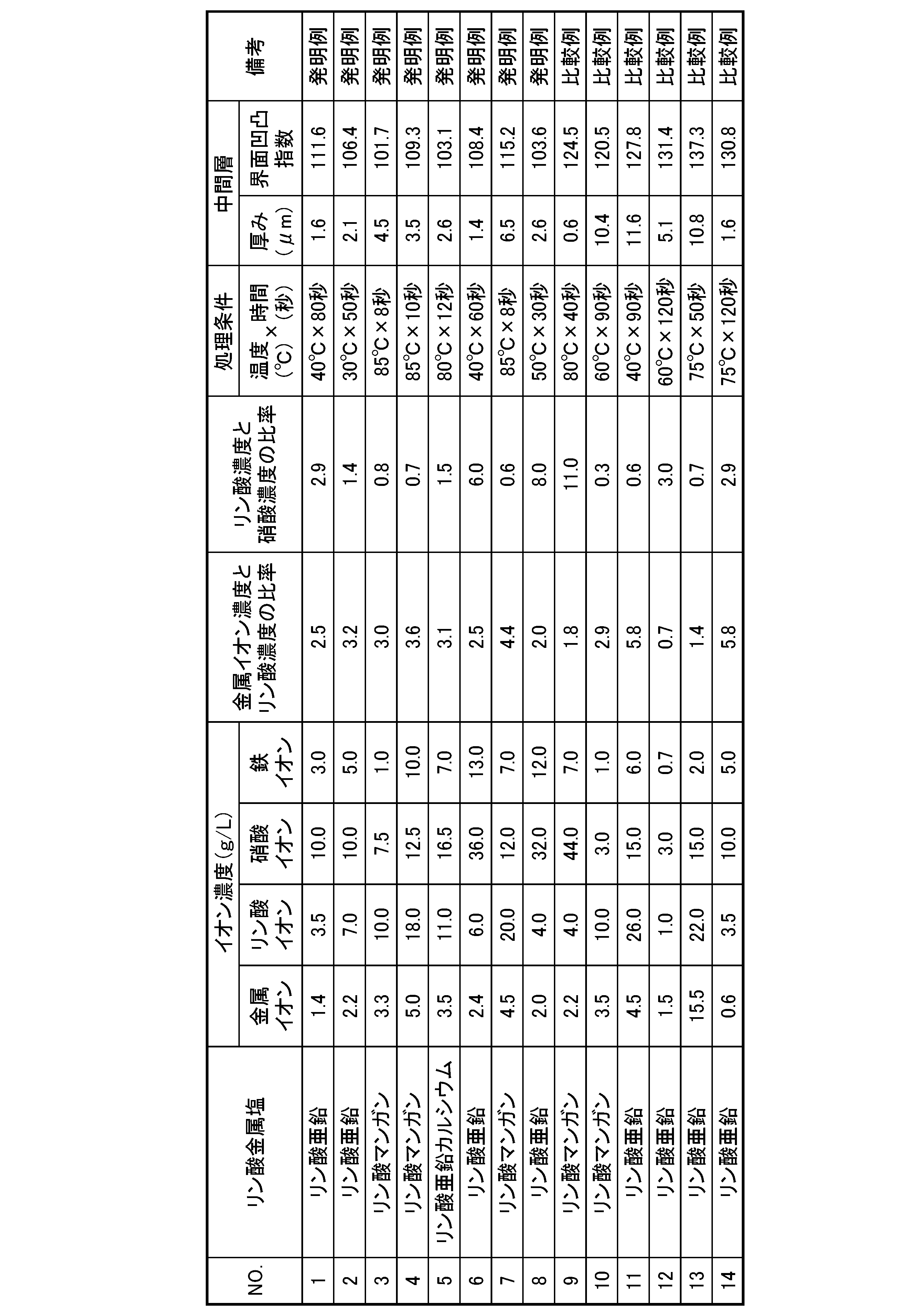
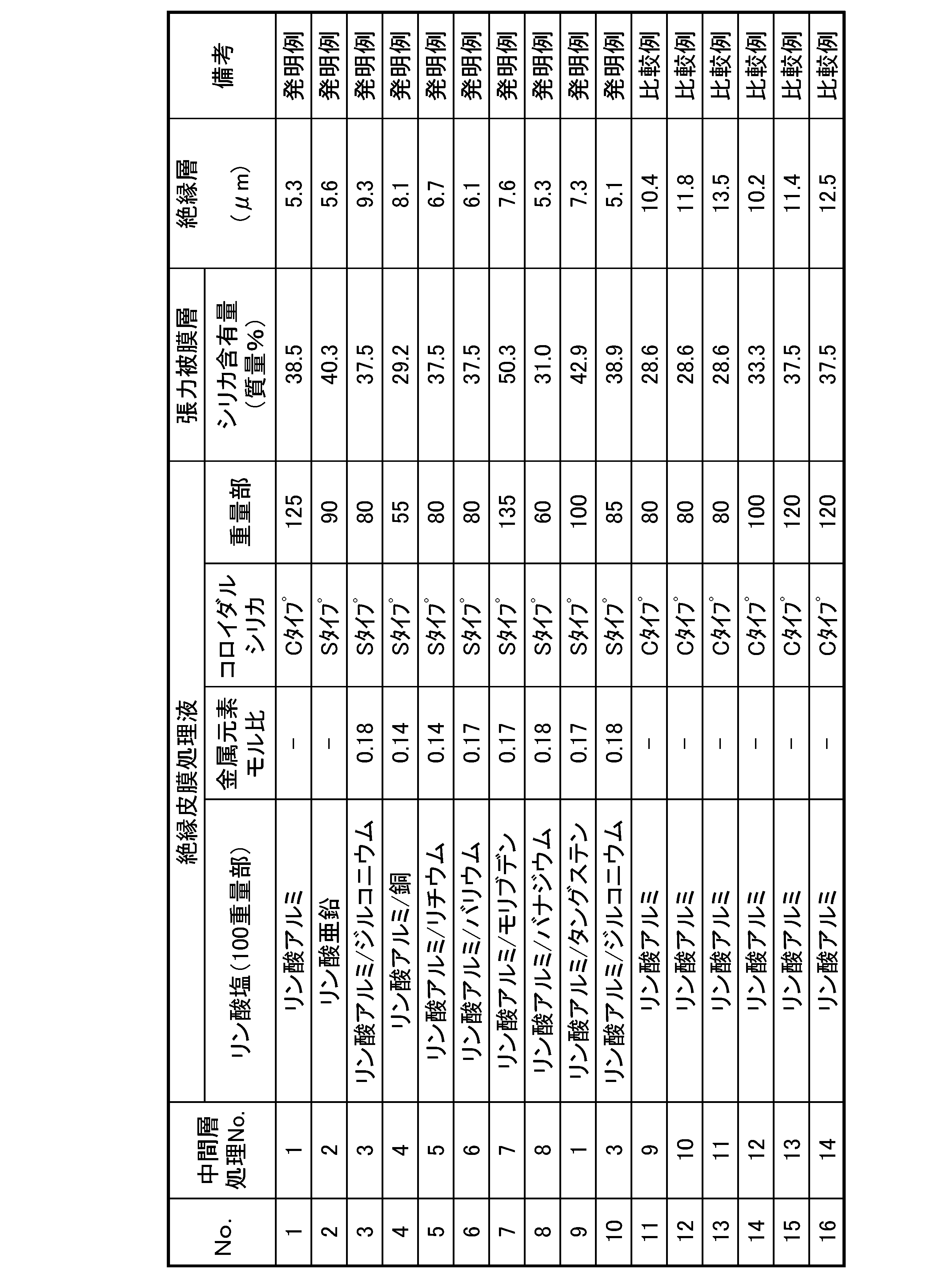

一方、比較例では、被膜密着性、磁気特性、耐食性、耐溶出性、トランス(コア)の占積率の1つ以上が劣っていた。
1 母材鋼板
2 絶縁被膜
21 中間層
22 張力被膜層
Claims (5)
- 母材鋼板と、
前記母材鋼板の表面に形成された絶縁被膜と、
を有し、
前記絶縁被膜が、
前記母材鋼板側に形成され、結晶性リン酸金属塩を含む中間層と、
前記絶縁被膜の表面側に形成された張力被膜層と、を有し、
前記中間層の厚み方向に沿った断面において、前記母材鋼板と前記中間層の界面を走査型電子顕微鏡によって5000倍で観察した際、観察画像幅Wに対する界面長Lの比率が100.0~120.0%であることを特徴とする方向性電磁鋼板。 - 前記張力被膜層が、リン酸金属塩とシリカを含むことを特徴とする、請求項1に記載の方向性電磁鋼板。
- 請求項1に記載の方向性電磁鋼板が備える前記絶縁被膜を形成する方法であって、
鋼板に、Al2O3を10~100質量%を含む焼鈍分離剤を塗布し、乾燥させた後、仕上げ焼鈍を行う仕上げ焼鈍工程と、
前記仕上げ焼鈍工程後の前記鋼板に対し、余剰の前記焼鈍分離剤を除去する焼鈍分離剤除去工程と、
前記焼鈍分離剤除去工程後の前記鋼板に、0.1から5質量%の硫酸、塩素酸、硝酸、リン酸から選択される1種の無機酸で1秒から20秒の条件で酸洗を行う酸洗工程と、
前記酸洗工程後の前記鋼板を、リン酸金属塩と酸化剤と鉄イオンを含む処理液に浸漬する浸漬工程と、
前記浸漬工程後の前記鋼板を前記処理液から引き上げ、余剰の前記処理液を除去した後、乾燥させる乾燥工程と、
前記乾燥工程後の前記鋼板に、リン酸金属塩とコロイダルシリカとを含み、かつ、リン酸金属塩とコロイダルシリカの合計濃度が固形分で10~40質量%であるコーティング液を塗布し、乾燥させ、その後、板温が700~950℃の状態で10~120秒間保持する、張力被膜層形成工程と、
を備え、
前記処理液が、
金属イオン濃度:1.0~10.0g/L、
リン酸イオン濃度:2.0~25.0g/L、
硝酸イオン濃度が2.0~40.0g/L、
鉄イオン濃度が1.0~20.0g/L、
であり、
金属イオン濃度に対するリン酸イオン濃度の比が1.5~5.0、
リン酸イオン濃度に対する硝酸イオン濃度の比が0.5~10.0であることを特徴とする絶縁被膜の形成方法。 - 前記浸漬工程において、前記酸洗工程後の前記鋼板を、液温が20~85℃の前記処理液に2~60秒間浸漬することを特徴とする請求項3に記載の絶縁被膜の形成方法。
- 前記硝酸イオン濃度が2.0~25.0g/Lであることを特徴とする請求項3に記載の絶縁被膜の形成方法。
Priority Applications (4)
| Application Number | Priority Date | Filing Date | Title |
|---|---|---|---|
| KR1020257034143A KR20250163937A (ko) | 2023-04-12 | 2024-04-12 | 방향성 전자 강판 및 절연 피막의 형성 방법 |
| EP24788840.7A EP4696809A1 (en) | 2023-04-12 | 2024-04-12 | Grain-oriented electrical steel sheet and method for forming insulating coating film |
| JP2025514033A JPWO2024214818A1 (ja) | 2023-04-12 | 2024-04-12 | |
| CN202480024429.6A CN120958172A (zh) | 2023-04-12 | 2024-04-12 | 取向性电磁钢板和绝缘覆膜的形成方法 |
Applications Claiming Priority (2)
| Application Number | Priority Date | Filing Date | Title |
|---|---|---|---|
| JP2023064826 | 2023-04-12 | ||
| JP2023-064826 | 2023-04-12 |
Publications (1)
| Publication Number | Publication Date |
|---|---|
| WO2024214818A1 true WO2024214818A1 (ja) | 2024-10-17 |
Family
ID=93059612
Family Applications (1)
| Application Number | Title | Priority Date | Filing Date |
|---|---|---|---|
| PCT/JP2024/014841 Ceased WO2024214818A1 (ja) | 2023-04-12 | 2024-04-12 | 方向性電磁鋼板および絶縁被膜の形成方法 |
Country Status (5)
| Country | Link |
|---|---|
| EP (1) | EP4696809A1 (ja) |
| JP (1) | JPWO2024214818A1 (ja) |
| KR (1) | KR20250163937A (ja) |
| CN (1) | CN120958172A (ja) |
| WO (1) | WO2024214818A1 (ja) |
Citations (12)
| Publication number | Priority date | Publication date | Assignee | Title |
|---|---|---|---|---|
| JPS4839338A (ja) | 1971-09-27 | 1973-06-09 | ||
| JPS4996920A (ja) | 1973-01-22 | 1974-09-13 | ||
| JPS60240108A (ja) * | 1984-05-14 | 1985-11-29 | Kawasaki Steel Corp | 超低鉄損方向性けい素鋼板およびその製造方法 |
| JPH05279747A (ja) * | 1992-04-02 | 1993-10-26 | Nippon Steel Corp | 方向性電磁鋼板の絶縁皮膜形成方法 |
| JPH06184762A (ja) | 1992-08-25 | 1994-07-05 | Nippon Steel Corp | 一方向性珪素鋼板の絶縁皮膜形成方法 |
| JPH11209891A (ja) | 1997-10-14 | 1999-08-03 | Nippon Steel Corp | 電磁鋼板の絶縁皮膜形成方法 |
| JP2005139481A (ja) | 2003-11-04 | 2005-06-02 | Nippon Steel Corp | 張力付与性絶縁皮膜の皮膜密着性に優れる一方向性珪素鋼板の製造方法 |
| JP2016145419A (ja) * | 2015-01-30 | 2016-08-12 | Jfeスチール株式会社 | 方向性電磁鋼板とその製造方法 |
| WO2019013347A1 (ja) * | 2017-07-13 | 2019-01-17 | 新日鐵住金株式会社 | 方向性電磁鋼板、及び方向性電磁鋼板の製造方法 |
| WO2022215709A1 (ja) * | 2021-04-06 | 2022-10-13 | 日本製鉄株式会社 | 方向性電磁鋼板及び絶縁被膜の形成方法 |
| WO2022215710A1 (ja) | 2021-04-06 | 2022-10-13 | 日本製鉄株式会社 | 方向性電磁鋼板及び絶縁被膜の形成方法 |
| JP2023064826A (ja) | 2021-10-27 | 2023-05-12 | トヨタ自動車株式会社 | 複合溶射材料及びその製造方法、これを用いた電極 |
-
2024
- 2024-04-12 EP EP24788840.7A patent/EP4696809A1/en active Pending
- 2024-04-12 KR KR1020257034143A patent/KR20250163937A/ko active Pending
- 2024-04-12 WO PCT/JP2024/014841 patent/WO2024214818A1/ja not_active Ceased
- 2024-04-12 CN CN202480024429.6A patent/CN120958172A/zh active Pending
- 2024-04-12 JP JP2025514033A patent/JPWO2024214818A1/ja active Pending
Patent Citations (12)
| Publication number | Priority date | Publication date | Assignee | Title |
|---|---|---|---|---|
| JPS4839338A (ja) | 1971-09-27 | 1973-06-09 | ||
| JPS4996920A (ja) | 1973-01-22 | 1974-09-13 | ||
| JPS60240108A (ja) * | 1984-05-14 | 1985-11-29 | Kawasaki Steel Corp | 超低鉄損方向性けい素鋼板およびその製造方法 |
| JPH05279747A (ja) * | 1992-04-02 | 1993-10-26 | Nippon Steel Corp | 方向性電磁鋼板の絶縁皮膜形成方法 |
| JPH06184762A (ja) | 1992-08-25 | 1994-07-05 | Nippon Steel Corp | 一方向性珪素鋼板の絶縁皮膜形成方法 |
| JPH11209891A (ja) | 1997-10-14 | 1999-08-03 | Nippon Steel Corp | 電磁鋼板の絶縁皮膜形成方法 |
| JP2005139481A (ja) | 2003-11-04 | 2005-06-02 | Nippon Steel Corp | 張力付与性絶縁皮膜の皮膜密着性に優れる一方向性珪素鋼板の製造方法 |
| JP2016145419A (ja) * | 2015-01-30 | 2016-08-12 | Jfeスチール株式会社 | 方向性電磁鋼板とその製造方法 |
| WO2019013347A1 (ja) * | 2017-07-13 | 2019-01-17 | 新日鐵住金株式会社 | 方向性電磁鋼板、及び方向性電磁鋼板の製造方法 |
| WO2022215709A1 (ja) * | 2021-04-06 | 2022-10-13 | 日本製鉄株式会社 | 方向性電磁鋼板及び絶縁被膜の形成方法 |
| WO2022215710A1 (ja) | 2021-04-06 | 2022-10-13 | 日本製鉄株式会社 | 方向性電磁鋼板及び絶縁被膜の形成方法 |
| JP2023064826A (ja) | 2021-10-27 | 2023-05-12 | トヨタ自動車株式会社 | 複合溶射材料及びその製造方法、これを用いた電極 |
Non-Patent Citations (1)
| Title |
|---|
| See also references of EP4696809A1 |
Also Published As
| Publication number | Publication date |
|---|---|
| CN120958172A (zh) | 2025-11-14 |
| JPWO2024214818A1 (ja) | 2024-10-17 |
| EP4696809A1 (en) | 2026-02-18 |
| KR20250163937A (ko) | 2025-11-21 |
Similar Documents
| Publication | Publication Date | Title |
|---|---|---|
| JP7678366B2 (ja) | 方向性電磁鋼板及び絶縁被膜の形成方法 | |
| JP7727214B2 (ja) | 方向性電磁鋼板及び絶縁被膜の形成方法 | |
| WO2019013351A1 (ja) | 方向性電磁鋼板及びその製造方法 | |
| JP7727215B2 (ja) | 方向性電磁鋼板及び絶縁被膜の形成方法 | |
| JP7553869B2 (ja) | 方向性電磁鋼板 | |
| JP7783550B2 (ja) | 方向性電磁鋼板および絶縁被膜の形成方法 | |
| JP7787460B2 (ja) | 方向性電磁鋼板及び絶縁被膜の形成方法 | |
| JP7817624B2 (ja) | 方向性電磁鋼板及び絶縁被膜の形成方法 | |
| JP7748016B2 (ja) | 方向性電磁鋼板および絶縁被膜の形成方法 | |
| JP7795149B2 (ja) | 方向性電磁鋼板および絶縁被膜の形成方法 | |
| JP7730076B2 (ja) | 方向性電磁鋼板および絶縁被膜の形成方法 | |
| JP7748015B2 (ja) | 方向性電磁鋼板および絶縁被膜の形成方法 | |
| EP4696809A1 (en) | Grain-oriented electrical steel sheet and method for forming insulating coating film | |
| WO2025170057A1 (ja) | 方向性電磁鋼板及びその製造方法 | |
| RU2842744C2 (ru) | Лист электротехнической стали с ориентированной зеренной структурой и способ формирования изоляционного покрытия | |
| WO2025170056A1 (ja) | 方向性電磁鋼板及び絶縁被膜の形成方法 | |
| WO2024171608A1 (ja) | 方向性電磁鋼板、並びに、方向性電磁鋼板の中間層および絶縁被膜の形成方法 | |
| WO2025170059A1 (ja) | 方向性電磁鋼板及び絶縁被膜の形成方法 | |
| WO2024210203A1 (ja) | 方向性電磁鋼板及び絶縁被膜形成方法 |
Legal Events
| Date | Code | Title | Description |
|---|---|---|---|
| 121 | Ep: the epo has been informed by wipo that ep was designated in this application |
Ref document number: 24788840 Country of ref document: EP Kind code of ref document: A1 |
|
| WWE | Wipo information: entry into national phase |
Ref document number: 2025514033 Country of ref document: JP |
|
| WWE | Wipo information: entry into national phase |
Ref document number: 202517095059 Country of ref document: IN |
|
| ENP | Entry into the national phase |
Ref document number: 1020257034143 Country of ref document: KR Free format text: ST27 STATUS EVENT CODE: A-0-1-A10-A15-NAP-PA0105 (AS PROVIDED BY THE NATIONAL OFFICE) |
|
| WWE | Wipo information: entry into national phase |
Ref document number: KR1020257034143 Country of ref document: KR Ref document number: 1020257034143 Country of ref document: KR |
|
| REG | Reference to national code |
Ref country code: BR Ref legal event code: B01A Ref document number: 112025021738 Country of ref document: BR |
|
| WWE | Wipo information: entry into national phase |
Ref document number: 2024788840 Country of ref document: EP Ref document number: 2025128366 Country of ref document: RU |
|
| NENP | Non-entry into the national phase |
Ref country code: DE |
|
| WWP | Wipo information: published in national office |
Ref document number: 202517095059 Country of ref document: IN |
|
| ENP | Entry into the national phase |
Ref document number: 2024788840 Country of ref document: EP Effective date: 20251112 |
|
| WWP | Wipo information: published in national office |
Ref document number: 2025128366 Country of ref document: RU |
|
| ENP | Entry into the national phase |
Ref document number: 2024788840 Country of ref document: EP Effective date: 20251112 |
|
| ENP | Entry into the national phase |
Ref document number: 2024788840 Country of ref document: EP Effective date: 20251112 |
|
| ENP | Entry into the national phase |
Ref document number: 2024788840 Country of ref document: EP Effective date: 20251112 |
|
| ENP | Entry into the national phase |
Ref document number: 2024788840 Country of ref document: EP Effective date: 20251112 |
|
| ENP | Entry into the national phase |
Ref document number: 2024788840 Country of ref document: EP Effective date: 20251112 |
|
| ENP | Entry into the national phase |
Ref document number: 2024788840 Country of ref document: EP Effective date: 20251112 |
|
| ENP | Entry into the national phase |
Ref document number: 2024788840 Country of ref document: EP Effective date: 20251112 |
|
| ENP | Entry into the national phase |
Ref document number: 2024788840 Country of ref document: EP Effective date: 20251112 |
|
| WWP | Wipo information: published in national office |
Ref document number: 2024788840 Country of ref document: EP |