WO2024224581A1 - 溶融亜鉛系めっき鋼板の製造方法 - Google Patents
溶融亜鉛系めっき鋼板の製造方法 Download PDFInfo
- Publication number
- WO2024224581A1 WO2024224581A1 PCT/JP2023/016784 JP2023016784W WO2024224581A1 WO 2024224581 A1 WO2024224581 A1 WO 2024224581A1 JP 2023016784 W JP2023016784 W JP 2023016784W WO 2024224581 A1 WO2024224581 A1 WO 2024224581A1
- Authority
- WO
- WIPO (PCT)
- Prior art keywords
- steel sheet
- hot
- less
- annealing
- dip galvanized
- Prior art date
- Legal status (The legal status is an assumption and is not a legal conclusion. Google has not performed a legal analysis and makes no representation as to the accuracy of the status listed.)
- Ceased
Links
Classifications
-
- C—CHEMISTRY; METALLURGY
- C22—METALLURGY; FERROUS OR NON-FERROUS ALLOYS; TREATMENT OF ALLOYS OR NON-FERROUS METALS
- C22C—ALLOYS
- C22C38/00—Ferrous alloys, e.g. steel alloys
- C22C38/60—Ferrous alloys, e.g. steel alloys containing lead, selenium, tellurium, or antimony, or more than 0.04% by weight of sulfur
-
- C—CHEMISTRY; METALLURGY
- C21—METALLURGY OF IRON
- C21D—MODIFYING THE PHYSICAL STRUCTURE OF FERROUS METALS; GENERAL DEVICES FOR HEAT TREATMENT OF FERROUS OR NON-FERROUS METALS OR ALLOYS; MAKING METAL MALLEABLE, e.g. BY DECARBURISATION OR TEMPERING
- C21D1/00—General methods or devices for heat treatment, e.g. annealing, hardening, quenching or tempering
- C21D1/06—Surface hardening
-
- C—CHEMISTRY; METALLURGY
- C21—METALLURGY OF IRON
- C21D—MODIFYING THE PHYSICAL STRUCTURE OF FERROUS METALS; GENERAL DEVICES FOR HEAT TREATMENT OF FERROUS OR NON-FERROUS METALS OR ALLOYS; MAKING METAL MALLEABLE, e.g. BY DECARBURISATION OR TEMPERING
- C21D1/00—General methods or devices for heat treatment, e.g. annealing, hardening, quenching or tempering
- C21D1/26—Methods of annealing
-
- C—CHEMISTRY; METALLURGY
- C21—METALLURGY OF IRON
- C21D—MODIFYING THE PHYSICAL STRUCTURE OF FERROUS METALS; GENERAL DEVICES FOR HEAT TREATMENT OF FERROUS OR NON-FERROUS METALS OR ALLOYS; MAKING METAL MALLEABLE, e.g. BY DECARBURISATION OR TEMPERING
- C21D1/00—General methods or devices for heat treatment, e.g. annealing, hardening, quenching or tempering
- C21D1/74—Methods of treatment in inert gas, controlled atmosphere, vacuum or pulverulent material
- C21D1/76—Adjusting the composition of the atmosphere
-
- C—CHEMISTRY; METALLURGY
- C21—METALLURGY OF IRON
- C21D—MODIFYING THE PHYSICAL STRUCTURE OF FERROUS METALS; GENERAL DEVICES FOR HEAT TREATMENT OF FERROUS OR NON-FERROUS METALS OR ALLOYS; MAKING METAL MALLEABLE, e.g. BY DECARBURISATION OR TEMPERING
- C21D6/00—Heat treatment of ferrous alloys
- C21D6/002—Heat treatment of ferrous alloys containing Cr
-
- C—CHEMISTRY; METALLURGY
- C21—METALLURGY OF IRON
- C21D—MODIFYING THE PHYSICAL STRUCTURE OF FERROUS METALS; GENERAL DEVICES FOR HEAT TREATMENT OF FERROUS OR NON-FERROUS METALS OR ALLOYS; MAKING METAL MALLEABLE, e.g. BY DECARBURISATION OR TEMPERING
- C21D8/00—Modifying the physical properties of ferrous metals or ferrous alloys by deformation combined with, or followed by, heat treatment
- C21D8/02—Modifying the physical properties of ferrous metals or ferrous alloys by deformation combined with, or followed by, heat treatment during manufacturing of plates or strips
- C21D8/0247—Modifying the physical properties of ferrous metals or ferrous alloys by deformation combined with, or followed by, heat treatment during manufacturing of plates or strips characterised by the heat treatment
-
- C—CHEMISTRY; METALLURGY
- C21—METALLURGY OF IRON
- C21D—MODIFYING THE PHYSICAL STRUCTURE OF FERROUS METALS; GENERAL DEVICES FOR HEAT TREATMENT OF FERROUS OR NON-FERROUS METALS OR ALLOYS; MAKING METAL MALLEABLE, e.g. BY DECARBURISATION OR TEMPERING
- C21D8/00—Modifying the physical properties of ferrous metals or ferrous alloys by deformation combined with, or followed by, heat treatment
- C21D8/02—Modifying the physical properties of ferrous metals or ferrous alloys by deformation combined with, or followed by, heat treatment during manufacturing of plates or strips
- C21D8/0247—Modifying the physical properties of ferrous metals or ferrous alloys by deformation combined with, or followed by, heat treatment during manufacturing of plates or strips characterised by the heat treatment
- C21D8/0257—Modifying the physical properties of ferrous metals or ferrous alloys by deformation combined with, or followed by, heat treatment during manufacturing of plates or strips characterised by the heat treatment with diffusion of elements, e.g. decarburising, nitriding
-
- C—CHEMISTRY; METALLURGY
- C21—METALLURGY OF IRON
- C21D—MODIFYING THE PHYSICAL STRUCTURE OF FERROUS METALS; GENERAL DEVICES FOR HEAT TREATMENT OF FERROUS OR NON-FERROUS METALS OR ALLOYS; MAKING METAL MALLEABLE, e.g. BY DECARBURISATION OR TEMPERING
- C21D9/00—Heat treatment, e.g. annealing, hardening, quenching or tempering, adapted for particular articles; Furnaces therefor
- C21D9/46—Heat treatment, e.g. annealing, hardening, quenching or tempering, adapted for particular articles; Furnaces therefor for sheet metals
-
- C—CHEMISTRY; METALLURGY
- C21—METALLURGY OF IRON
- C21D—MODIFYING THE PHYSICAL STRUCTURE OF FERROUS METALS; GENERAL DEVICES FOR HEAT TREATMENT OF FERROUS OR NON-FERROUS METALS OR ALLOYS; MAKING METAL MALLEABLE, e.g. BY DECARBURISATION OR TEMPERING
- C21D9/00—Heat treatment, e.g. annealing, hardening, quenching or tempering, adapted for particular articles; Furnaces therefor
- C21D9/52—Heat treatment, e.g. annealing, hardening, quenching or tempering, adapted for particular articles; Furnaces therefor for wires; for strips ; for rods of unlimited length
- C21D9/54—Furnaces for treating strips or wire
- C21D9/56—Continuous furnaces for strip or wire
- C21D9/561—Continuous furnaces for strip or wire with a controlled atmosphere or vacuum
-
- C—CHEMISTRY; METALLURGY
- C22—METALLURGY; FERROUS OR NON-FERROUS ALLOYS; TREATMENT OF ALLOYS OR NON-FERROUS METALS
- C22C—ALLOYS
- C22C38/00—Ferrous alloys, e.g. steel alloys
- C22C38/002—Ferrous alloys, e.g. steel alloys containing In, Mg, or other elements not provided for in one single group C22C38/001 - C22C38/60
-
- C—CHEMISTRY; METALLURGY
- C22—METALLURGY; FERROUS OR NON-FERROUS ALLOYS; TREATMENT OF ALLOYS OR NON-FERROUS METALS
- C22C—ALLOYS
- C22C38/00—Ferrous alloys, e.g. steel alloys
- C22C38/005—Ferrous alloys, e.g. steel alloys containing rare earths, i.e. Sc, Y, Lanthanides
-
- C—CHEMISTRY; METALLURGY
- C22—METALLURGY; FERROUS OR NON-FERROUS ALLOYS; TREATMENT OF ALLOYS OR NON-FERROUS METALS
- C22C—ALLOYS
- C22C38/00—Ferrous alloys, e.g. steel alloys
- C22C38/008—Ferrous alloys, e.g. steel alloys containing tin
-
- C—CHEMISTRY; METALLURGY
- C22—METALLURGY; FERROUS OR NON-FERROUS ALLOYS; TREATMENT OF ALLOYS OR NON-FERROUS METALS
- C22C—ALLOYS
- C22C38/00—Ferrous alloys, e.g. steel alloys
- C22C38/02—Ferrous alloys, e.g. steel alloys containing silicon
-
- C—CHEMISTRY; METALLURGY
- C22—METALLURGY; FERROUS OR NON-FERROUS ALLOYS; TREATMENT OF ALLOYS OR NON-FERROUS METALS
- C22C—ALLOYS
- C22C38/00—Ferrous alloys, e.g. steel alloys
- C22C38/04—Ferrous alloys, e.g. steel alloys containing manganese
-
- C—CHEMISTRY; METALLURGY
- C22—METALLURGY; FERROUS OR NON-FERROUS ALLOYS; TREATMENT OF ALLOYS OR NON-FERROUS METALS
- C22C—ALLOYS
- C22C38/00—Ferrous alloys, e.g. steel alloys
- C22C38/08—Ferrous alloys, e.g. steel alloys containing nickel
-
- C—CHEMISTRY; METALLURGY
- C22—METALLURGY; FERROUS OR NON-FERROUS ALLOYS; TREATMENT OF ALLOYS OR NON-FERROUS METALS
- C22C—ALLOYS
- C22C38/00—Ferrous alloys, e.g. steel alloys
- C22C38/12—Ferrous alloys, e.g. steel alloys containing tungsten, tantalum, molybdenum, vanadium, or niobium
-
- C—CHEMISTRY; METALLURGY
- C22—METALLURGY; FERROUS OR NON-FERROUS ALLOYS; TREATMENT OF ALLOYS OR NON-FERROUS METALS
- C22C—ALLOYS
- C22C38/00—Ferrous alloys, e.g. steel alloys
- C22C38/14—Ferrous alloys, e.g. steel alloys containing titanium or zirconium
-
- C—CHEMISTRY; METALLURGY
- C22—METALLURGY; FERROUS OR NON-FERROUS ALLOYS; TREATMENT OF ALLOYS OR NON-FERROUS METALS
- C22C—ALLOYS
- C22C38/00—Ferrous alloys, e.g. steel alloys
- C22C38/16—Ferrous alloys, e.g. steel alloys containing copper
-
- C—CHEMISTRY; METALLURGY
- C22—METALLURGY; FERROUS OR NON-FERROUS ALLOYS; TREATMENT OF ALLOYS OR NON-FERROUS METALS
- C22C—ALLOYS
- C22C38/00—Ferrous alloys, e.g. steel alloys
- C22C38/18—Ferrous alloys, e.g. steel alloys containing chromium
- C22C38/38—Ferrous alloys, e.g. steel alloys containing chromium with more than 1.5% by weight of manganese
-
- C—CHEMISTRY; METALLURGY
- C23—COATING METALLIC MATERIAL; COATING MATERIAL WITH METALLIC MATERIAL; CHEMICAL SURFACE TREATMENT; DIFFUSION TREATMENT OF METALLIC MATERIAL; COATING BY VACUUM EVAPORATION, BY SPUTTERING, BY ION IMPLANTATION OR BY CHEMICAL VAPOUR DEPOSITION, IN GENERAL; INHIBITING CORROSION OF METALLIC MATERIAL OR INCRUSTATION IN GENERAL
- C23C—COATING METALLIC MATERIAL; COATING MATERIAL WITH METALLIC MATERIAL; SURFACE TREATMENT OF METALLIC MATERIAL BY DIFFUSION INTO THE SURFACE, BY CHEMICAL CONVERSION OR SUBSTITUTION; COATING BY VACUUM EVAPORATION, BY SPUTTERING, BY ION IMPLANTATION OR BY CHEMICAL VAPOUR DEPOSITION, IN GENERAL
- C23C2/00—Hot-dipping or immersion processes for applying the coating material in the molten state without affecting the shape; Apparatus therefor
- C23C2/02—Pretreatment of the material to be coated, e.g. for coating on selected surface areas
-
- C—CHEMISTRY; METALLURGY
- C23—COATING METALLIC MATERIAL; COATING MATERIAL WITH METALLIC MATERIAL; CHEMICAL SURFACE TREATMENT; DIFFUSION TREATMENT OF METALLIC MATERIAL; COATING BY VACUUM EVAPORATION, BY SPUTTERING, BY ION IMPLANTATION OR BY CHEMICAL VAPOUR DEPOSITION, IN GENERAL; INHIBITING CORROSION OF METALLIC MATERIAL OR INCRUSTATION IN GENERAL
- C23C—COATING METALLIC MATERIAL; COATING MATERIAL WITH METALLIC MATERIAL; SURFACE TREATMENT OF METALLIC MATERIAL BY DIFFUSION INTO THE SURFACE, BY CHEMICAL CONVERSION OR SUBSTITUTION; COATING BY VACUUM EVAPORATION, BY SPUTTERING, BY ION IMPLANTATION OR BY CHEMICAL VAPOUR DEPOSITION, IN GENERAL
- C23C2/00—Hot-dipping or immersion processes for applying the coating material in the molten state without affecting the shape; Apparatus therefor
- C23C2/02—Pretreatment of the material to be coated, e.g. for coating on selected surface areas
- C23C2/022—Pretreatment of the material to be coated, e.g. for coating on selected surface areas by heating
- C23C2/0222—Pretreatment of the material to be coated, e.g. for coating on selected surface areas by heating in a reactive atmosphere, e.g. oxidising or reducing atmosphere
-
- C—CHEMISTRY; METALLURGY
- C23—COATING METALLIC MATERIAL; COATING MATERIAL WITH METALLIC MATERIAL; CHEMICAL SURFACE TREATMENT; DIFFUSION TREATMENT OF METALLIC MATERIAL; COATING BY VACUUM EVAPORATION, BY SPUTTERING, BY ION IMPLANTATION OR BY CHEMICAL VAPOUR DEPOSITION, IN GENERAL; INHIBITING CORROSION OF METALLIC MATERIAL OR INCRUSTATION IN GENERAL
- C23C—COATING METALLIC MATERIAL; COATING MATERIAL WITH METALLIC MATERIAL; SURFACE TREATMENT OF METALLIC MATERIAL BY DIFFUSION INTO THE SURFACE, BY CHEMICAL CONVERSION OR SUBSTITUTION; COATING BY VACUUM EVAPORATION, BY SPUTTERING, BY ION IMPLANTATION OR BY CHEMICAL VAPOUR DEPOSITION, IN GENERAL
- C23C2/00—Hot-dipping or immersion processes for applying the coating material in the molten state without affecting the shape; Apparatus therefor
- C23C2/02—Pretreatment of the material to be coated, e.g. for coating on selected surface areas
- C23C2/022—Pretreatment of the material to be coated, e.g. for coating on selected surface areas by heating
- C23C2/0224—Two or more thermal pretreatments
-
- C—CHEMISTRY; METALLURGY
- C23—COATING METALLIC MATERIAL; COATING MATERIAL WITH METALLIC MATERIAL; CHEMICAL SURFACE TREATMENT; DIFFUSION TREATMENT OF METALLIC MATERIAL; COATING BY VACUUM EVAPORATION, BY SPUTTERING, BY ION IMPLANTATION OR BY CHEMICAL VAPOUR DEPOSITION, IN GENERAL; INHIBITING CORROSION OF METALLIC MATERIAL OR INCRUSTATION IN GENERAL
- C23C—COATING METALLIC MATERIAL; COATING MATERIAL WITH METALLIC MATERIAL; SURFACE TREATMENT OF METALLIC MATERIAL BY DIFFUSION INTO THE SURFACE, BY CHEMICAL CONVERSION OR SUBSTITUTION; COATING BY VACUUM EVAPORATION, BY SPUTTERING, BY ION IMPLANTATION OR BY CHEMICAL VAPOUR DEPOSITION, IN GENERAL
- C23C2/00—Hot-dipping or immersion processes for applying the coating material in the molten state without affecting the shape; Apparatus therefor
- C23C2/04—Hot-dipping or immersion processes for applying the coating material in the molten state without affecting the shape; Apparatus therefor characterised by the coating material
- C23C2/06—Zinc or cadmium or alloys based thereon
-
- C—CHEMISTRY; METALLURGY
- C23—COATING METALLIC MATERIAL; COATING MATERIAL WITH METALLIC MATERIAL; CHEMICAL SURFACE TREATMENT; DIFFUSION TREATMENT OF METALLIC MATERIAL; COATING BY VACUUM EVAPORATION, BY SPUTTERING, BY ION IMPLANTATION OR BY CHEMICAL VAPOUR DEPOSITION, IN GENERAL; INHIBITING CORROSION OF METALLIC MATERIAL OR INCRUSTATION IN GENERAL
- C23C—COATING METALLIC MATERIAL; COATING MATERIAL WITH METALLIC MATERIAL; SURFACE TREATMENT OF METALLIC MATERIAL BY DIFFUSION INTO THE SURFACE, BY CHEMICAL CONVERSION OR SUBSTITUTION; COATING BY VACUUM EVAPORATION, BY SPUTTERING, BY ION IMPLANTATION OR BY CHEMICAL VAPOUR DEPOSITION, IN GENERAL
- C23C2/00—Hot-dipping or immersion processes for applying the coating material in the molten state without affecting the shape; Apparatus therefor
- C23C2/26—After-treatment
- C23C2/28—Thermal after-treatment, e.g. treatment in oil bath
-
- C—CHEMISTRY; METALLURGY
- C23—COATING METALLIC MATERIAL; COATING MATERIAL WITH METALLIC MATERIAL; CHEMICAL SURFACE TREATMENT; DIFFUSION TREATMENT OF METALLIC MATERIAL; COATING BY VACUUM EVAPORATION, BY SPUTTERING, BY ION IMPLANTATION OR BY CHEMICAL VAPOUR DEPOSITION, IN GENERAL; INHIBITING CORROSION OF METALLIC MATERIAL OR INCRUSTATION IN GENERAL
- C23C—COATING METALLIC MATERIAL; COATING MATERIAL WITH METALLIC MATERIAL; SURFACE TREATMENT OF METALLIC MATERIAL BY DIFFUSION INTO THE SURFACE, BY CHEMICAL CONVERSION OR SUBSTITUTION; COATING BY VACUUM EVAPORATION, BY SPUTTERING, BY ION IMPLANTATION OR BY CHEMICAL VAPOUR DEPOSITION, IN GENERAL
- C23C2/00—Hot-dipping or immersion processes for applying the coating material in the molten state without affecting the shape; Apparatus therefor
- C23C2/34—Hot-dipping or immersion processes for applying the coating material in the molten state without affecting the shape; Apparatus therefor characterised by the shape of the material to be treated
- C23C2/36—Elongated material
- C23C2/40—Plates; Strips
-
- C—CHEMISTRY; METALLURGY
- C21—METALLURGY OF IRON
- C21D—MODIFYING THE PHYSICAL STRUCTURE OF FERROUS METALS; GENERAL DEVICES FOR HEAT TREATMENT OF FERROUS OR NON-FERROUS METALS OR ALLOYS; MAKING METAL MALLEABLE, e.g. BY DECARBURISATION OR TEMPERING
- C21D2211/00—Microstructure comprising significant phases
- C21D2211/001—Austenite
-
- C—CHEMISTRY; METALLURGY
- C21—METALLURGY OF IRON
- C21D—MODIFYING THE PHYSICAL STRUCTURE OF FERROUS METALS; GENERAL DEVICES FOR HEAT TREATMENT OF FERROUS OR NON-FERROUS METALS OR ALLOYS; MAKING METAL MALLEABLE, e.g. BY DECARBURISATION OR TEMPERING
- C21D2211/00—Microstructure comprising significant phases
- C21D2211/002—Bainite
-
- C—CHEMISTRY; METALLURGY
- C21—METALLURGY OF IRON
- C21D—MODIFYING THE PHYSICAL STRUCTURE OF FERROUS METALS; GENERAL DEVICES FOR HEAT TREATMENT OF FERROUS OR NON-FERROUS METALS OR ALLOYS; MAKING METAL MALLEABLE, e.g. BY DECARBURISATION OR TEMPERING
- C21D2211/00—Microstructure comprising significant phases
- C21D2211/008—Martensite
Definitions
- the present invention relates to a method for manufacturing hot-dip galvanized steel sheets.
- a hot-dip galvanized steel sheet is produced by using a hot-rolled steel sheet or a cold-rolled steel sheet as a base material, recrystallizing annealing the base steel sheet in an annealing furnace of a CGL, and then hot-dip galvanizing the base steel sheet.
- an alloyed hot-dip galvanized steel sheet is produced by further alloying the hot-dip galvanized steel sheet.
- the steel sheet In annealing, the steel sheet must be held in a reducing atmosphere containing hydrogen, at which time hydrogen in the furnace penetrates into the steel sheet, and when the steel sheet is subsequently cooled and hot-dip plated, it remains in the steel sheet as diffusible hydrogen in steel. Because plating does not allow hydrogen to pass through, the diffusible hydrogen in steel is not released from the steel sheet after plating, and there was an issue that delayed fracture resistance is reduced when the amount of diffusible hydrogen in steel is large. In particular, in high-strength steel sheets with a tensile strength of 780 MPa or more, hydrogen in the steel tends to remain after annealing, and there was an issue that delayed fracture resistance is significantly reduced.
- Patent Document 1 discloses a technique in which a hot-rolled steel sheet is subjected to a reduction treatment, then dehydrogenated at 450 to 550° C. in an atmosphere with a H2 concentration of 8 to 20%, and then hot-dip galvanized.
- Patent Document 2 discloses a technique for reducing the amount of hydrogen in a steel sheet by controlling the relationship between the annealing temperature in an annealing furnace and the hydrogen concentration to satisfy the following formula (1) in a method of performing reduction annealing on a hot-rolled steel sheet in the range of 650 to 950°C and then hot-dip galvanizing the steel sheet. 1 ⁇ H ⁇ -0.05 ⁇ RT+57.5...(1)
- H is the hydrogen concentration in the furnace and RT is the annealing temperature.
- Patent Document 3 discloses a technology for obtaining good surface quality in a method for performing hot-dip galvanizing after reduction annealing of a steel sheet containing Si, Mn, and Al, by controlling the hydrogen concentration in a furnace during reduction annealing to be 10 vol% or more, and the relationship between the hydrogen partial pressure and the water vapor partial pressure in a furnace atmosphere gas at 650°C or more and less than 750°C to satisfy the following formula (2), and similarly controlling the relationship between the hydrogen partial pressure and the water vapor partial pressure in a furnace atmosphere gas at 750°C or more and 950°C or less to satisfy the following formula (3). log(P H2O /P H2 ) ⁇ -1.55 (2) -0.91 ⁇ log(P H2O /P H2 ) ⁇ -0.635 (3)
- Patent Documents 1 and 2 are both intended to suppress blisters (plating bulges) in hot-rolled steel sheets, and in order to improve the delayed fracture resistance of high-strength steel sheets having an austenitic phase, it is necessary to further reduce the amount of hydrogen in the atmosphere to reduce hydrogen in the steel.
- the amount of hydrogen in the atmosphere is further reduced, selective oxidation of easily oxidizable elements such as Si and Mn contained in the high-strength steel sheet is promoted, which inhibits galvanization and makes it impossible to obtain good surface quality. Therefore, it is difficult to improve good surface quality and delayed fracture resistance with the method of uniformly reducing hydrogen in a furnace as described in Patent Documents 1 and 2.
- Patent Document 3 aims to improve the platability of steel containing Si, Mn, and Al and obtain good surface quality by changing the ratio of water vapor partial pressure to hydrogen partial pressure according to the annealing temperature.
- it is necessary to control the hydrogen concentration in the furnace to 10% or more, and no consideration is given to reducing the hydrogen concentration contained in the steel. As a result, it is difficult to improve the delayed fracture resistance of high-strength steel sheet.
- the object of the present invention is therefore to provide a manufacturing method that solves the problems of the prior art and produces hot-dip galvanized steel sheets that have a beautiful surface appearance free of uncoated areas and have excellent delayed fracture resistance.
- the present inventors have conducted extensive research to solve the above problems, and as a result have found that in a manufacturing method of a hot-dip galvanized steel sheet in which a steel sheet is annealed in a non-oxidizing atmosphere and then hot-dip galvanized, a hot-dip galvanized steel sheet having excellent coating appearance and delayed fracture resistance can be manufactured by optimizing the annealing conditions in a non-oxidizing atmosphere.
- the present invention has been made based on these findings, and the gist of the present invention is as follows.
- a method for producing a hot-dip galvanized steel sheet comprising annealing a steel sheet in a non-oxidizing atmosphere in a continuous annealing furnace and then subjecting the steel sheet to hot-dip galvanizing (including the case where an alloying treatment is performed after hot-dip galvanizing),
- the annealing is A first step of holding the steel sheet at a temperature of 650°C to 950°C in an atmosphere with a dew point of -55°C to +20°C and a hydrogen concentration of 5% by volume to 25% by volume for a period of 20 s to 150 s; and a second step of holding the steel sheet that has been subjected to the first step at a temperature of 700°C or higher and 950°C or lower in an atmosphere having a dew point of -50°C or higher and +20°C or lower and a hydrogen concentration of 0.2 vol% or higher and less than 5.0 vol% for a period of 30 s or higher and 300 s or lower.
- the steel sheet before the annealing is subjected to an oxidation treatment at a temperature of 400 ° C. or more and 900 ° C. or less in an atmosphere containing 1000 volume ppm or more of O 2.
- the steel sheet subjected to the annealing is cooled in an atmosphere having a dew point of -20°C or less and a hydrogen concentration of 5 vol% or more and 25 vol% or less in a temperature range from a final holding temperature in the annealing to 600°C at an average cooling rate of 5°C/s or more, and further cooled to a temperature of 150°C or more and less than 600°C, and then heated as necessary and immersed in a hot-dip galvanized plating bath to perform hot-dip galvanized plating.
- the annealing is performed in a first step with a high hydrogen concentration and a second step with a low hydrogen concentration, each under specific conditions, thereby making it possible to manufacture a hot-dip galvanized steel sheet that has a beautiful surface appearance without bare spots and has excellent delayed fracture resistance.
- the present invention by performing an oxidation treatment before the annealing and then performing the annealing under more limited conditions, it is possible to manufacture a hot-dip galvanized steel sheet that has a higher level of plating appearance and excellent delayed fracture resistance.
- the temperatures specified in the oxidation treatment, annealing, and cooling after annealing are all "steel sheet temperatures.”
- a non-oxidizing atmosphere refers to an atmosphere in which iron is not oxidized, and is an atmosphere in which selective oxidation of easily oxidizable additive elements such as Si and Mn is permitted.
- a reducing atmosphere refers to an atmosphere in which iron oxide can be reduced to iron.
- the type of hot-dip galvanized steel sheet to which the present invention is applied is not particularly limited as long as it is a plated steel sheet having a plating layer containing zinc as a main component, and includes hot-dip galvanized steel sheet (GI) and alloyed hot-dip galvanized steel sheet (GA), as well as hot-dip zinc-aluminum alloy plated steel sheet, hot-dip zinc-aluminum-silicon alloy plated steel sheet, hot-dip zinc-aluminum-magnesium alloy plated steel sheet, and the like, and there is no restriction on the detailed plating composition of each of them.
- GI hot-dip galvanized steel sheet
- GA alloyed hot-dip galvanized steel sheet
- the units of "%" for the content of each element in the composition of the steel sheet (also referred to as the base steel sheet or base steel sheet), the content of each element in the composition of the plating bath, and the degree of alloying of the plating layer are all “mass %”, and the units of "%” for the hydrogen concentration in the atmosphere during annealing and cooling are all "volume %”.
- “high strength” steel sheet means that the tensile strength TS of the steel sheet measured in accordance with JIS Z2241 (2011) is 590 MPa or more.
- the manufacturing method of the present invention is a method for manufacturing a hot-dip galvanized steel sheet in which a steel sheet is annealed in a non-oxidizing atmosphere and then hot-dip galvanized.
- the annealing in the non-oxidizing atmosphere has a first step and a second step.
- the steel sheet is annealed in a reducing atmosphere with a high hydrogen concentration and a specified dew point, thereby reducing naturally oxidized Fe present on the surface layer of the steel sheet.
- the steel sheet is annealed in a non-oxidizing atmosphere with a low hydrogen concentration and a specified dew point, and hydrogen dissolved in the steel is released from the steel sheet.
- the annealed steel sheet is cooled to a specified temperature, and then immersed in a hot-dip galvanized plating bath to be hot-dip galvanized.
- the manufacturing method of the present invention includes a case in which an alloying treatment is performed after hot-dip galvanized plating to manufacture an alloyed hot-dip galvanized plated steel sheet.
- the oxidation treatment and the subsequent annealing in a non-oxidizing atmosphere are usually performed in a continuous annealing furnace having, from the inlet side, an oxidation zone (a zone for the oxidation treatment), a reduction zone (a zone for the first step of annealing), a soaking zone (a zone for the second step of annealing), and a cooling zone.
- the oxidation treatment is not an essential step and can be carried out appropriately as necessary.
- the manufacturing method of the present invention will be described below in the order of oxidation treatment, annealing (first step, second step, and cooling after annealing), and hot-dip galvanizing.
- Oxidation treatment In the oxidation treatment, the steel sheet temperature is controlled to 400°C or more and 900°C or less in an atmosphere containing 1000 volume ppm or more of O2 , thereby forming Fe oxide on the steel sheet surface layer.
- the atmosphere for the oxidation treatment may contain one or more of N2 , CO, CO2 , H2O , and NOx in addition to O2 .
- N2 can be contained as an inert gas, CO as a gas for adjusting oxidation and reduction, CO2 as an inert gas, and H2O as a gas for adjusting oxidation and reduction.
- CO, CO2 , H2O , and NOx can be contained as fuel gas, gas derived from the steel sheet components to be annealed, impurity gas in the atmosphere, or fuel combustion gas.
- the steel sheet is oxidized by this oxidation treatment, and then reduced in the subsequent annealing (first step) to form a reduced iron layer on the surface layer of the steel sheet, thereby preventing Si and Mn from diffusing into the surface layer of the steel sheet and being oxidized, thereby further improving the galvanizability.
- the oxidation treatment in an atmosphere containing 1000 volume ppm or more of O2 is an extremely important step in improving and simultaneously achieving both excellent surface quality and excellent delayed fracture resistance to a high level. Furthermore, the improvement effect is particularly remarkable in steel containing 0.1% or more of Si and 1.5% or more of Mn.
- the O2 concentration in the atmosphere in which the oxidation treatment is performed is 1000 ppm by volume or more, the oxidation of the steel sheet is promoted. If the O2 concentration is less than 1000 ppm by volume, the oxidation of the steel sheet becomes insufficient, and oxides of Si and Mn are formed, which may result in a decrease in galvanic properties.
- the atmosphere for the oxidation treatment may contain N2 , CO, CO2 , H2O , NOx, etc. depending on the gas used, and the ratios thereof are not particularly limited. Although a more beautiful surface appearance can be obtained by the oxidation treatment, this step is not an essential requirement because it is possible to obtain a hot-dip galvanized steel sheet having excellent delayed fracture resistance without the oxidation treatment.
- the oxidation of the steel sheet is promoted by setting the steel sheet temperature to 400° C. or higher. If the steel sheet temperature is less than 400° C., the amount of oxidation becomes insufficient, and oxides of Si and Mn are formed, which may reduce the effect of improving the galvanic property. On the other hand, if the steel sheet temperature exceeds 900°C, the amount of oxidation of the steel sheet becomes excessive, and the reduction is not completed in the subsequent reduction annealing (first step), and the remaining iron oxide may impair the galvanizing property. For this reason, the oxidation treatment is preferably performed at 400°C or higher and 900°C or lower.
- performing the oxidation treatment at 400°C or higher and 900°C or lower means that the oxidation treatment temperature is at least in the range of 400 to 900°C and does not exceed 900°C. Therefore, within this condition, part of the oxidation treatment may be performed at less than 400°C (for example, when the oxidation treatment is performed during the temperature rise process from 300°C to 700°C).
- the oxidation treatment is preferably carried out for a treatment time in the range of 1 to 30 seconds. That is, from the viewpoint of securing a sufficient amount of oxidation and improving plating properties, the treatment time is preferably 1 second or more, more preferably 2 seconds or more, and even more preferably 3 seconds or more. On the other hand, from the viewpoint of preventing excessive oxidation and suppressing pick-up, the treatment time is preferably 30 seconds or less, more preferably 20 seconds or less, and even more preferably 15 seconds or less.
- this oxidation treatment can utilize a process of heating the steel sheet to the annealing temperature.
- a temperature equalizing chamber capable of controlling the atmosphere can be provided, and the steel sheet surface can be oxidized by maintaining a constant temperature in a specified atmosphere. It is also possible to oxidize the steel sheet surface by controlling the atmosphere in the furnace while raising the temperature in a direct-fire heating furnace equipped with a direct-fire burner. By simultaneously raising the temperature and performing the oxidation treatment, the furnace can be made compact and the production speed can be improved, which is an industrial advantage.
- a sufficient amount of oxidation can be obtained by making the atmosphere oxidizing over a temperature rise range (temperature rise range) of 50°C or more after the steel sheet temperature reaches 400°C. If the temperature rise range in which the steel sheet is exposed to the oxidizing atmosphere is less than 50°C, the amount of oxidation becomes insufficient, and oxides of Si and Mn are formed, resulting in a decrease in the effect of improving the plating property.
- the heating rate within the oxidation temperature range is preferably 3 to 25°C/s to ensure an appropriate amount of oxidation.
- the direct flame burner for the oxidation treatment can be a burner that heats the steel plate by directly applying the burner flame, which is made by burning a mixture of fuel such as coke oven gas (COG), a by-product gas from steel mills, and air, to the surface of the steel plate.
- COG coke oven gas
- Heating with a direct flame burner has the advantage that the furnace length can be shortened and the steel plate conveying speed can be increased because the temperature of the steel plate is increased faster than by radiation heating means.
- the air ratio of the direct flame burner is set to 0.95 or more and the ratio of air to fuel is increased, unburned oxygen remains in the flame, and this oxygen can promote the oxidation of the steel plate. Therefore, by adjusting the air ratio, it is possible to control the oxygen concentration in the atmosphere.
- liquefied natural gas (LNG), ammonia gas, hydrogen gas, etc. can be used as fuel for the direct flame burner.
- First annealing step In the first annealing step, the steel sheet is held at a temperature of 650°C to 950°C for 20 s to 150 s in an atmosphere having a dew point of -55°C to +20°C and a hydrogen concentration of 5% to 25%, in which Fe oxide is reduced.
- Naturally occurring Fe oxide present on the surface layer of the steel sheet is reduced in a reducing atmosphere in the first step of annealing to ensure galvanic properties. Since the reduction hardly progresses in the subsequent second step in a low hydrogen concentration atmosphere, it is necessary to complete the reduction of Fe oxide in this first step. This first step is essential to obtain a good plating appearance.
- the annealing temperature of the steel sheet in the first step is less than 650°C, the reduction is insufficient, and the Fe oxide becomes roll pick-up, which causes defects in the steel sheet, and in the subsequent second step, the Fe oxide is not substantially reduced, which causes non-coating.
- the annealing temperature of the steel sheet exceeds 950°C, the furnace body life is significantly reduced. For this reason, the annealing temperature of the steel sheet is set to 650°C or more and 950°C or less.
- the annealing temperature is preferably set to 750°C or more from the viewpoint of recrystallizing the steel sheet to ensure a predetermined strength and ductility.
- the annealing temperature is preferably set to 780°C or more. Increasing the annealing temperature in the first step promotes the selective oxidation of Si and Mn and increases the amount of hydrogen in the steel. However, in the present invention, the atmosphere and holding time in the first and second steps are controlled, so that excellent surface quality and excellent resistance to delayed fracture can be provided.
- the dew point of the atmosphere in the first step is +20°C or less, which can reduce the Fe oxide in the steel sheet surface layer and suppress the selective oxidation of Si and Mn within a specified annealing time range.
- special equipment is required to lower the dew point, which increases costs.
- the dew point exceeds +20°C, the dew point distribution in the furnace becomes large, making dew point control difficult and raising concerns about the impact on the furnace body. For this reason, the dew point is set to -55°C or more and +20°C or less.
- the hydrogen concentration in the first step is set to 5% or more and 25% or less. Furthermore, if oxidation treatment is performed, the hydrogen concentration is preferably 8% or more to ensure sufficient reduction. On the other hand, from the viewpoint of running costs and reducing hydrogen in the steel, the hydrogen concentration is preferably 22% or less, and more preferably 18% or less.
- the holding time at 650°C to 950°C in the first step is less than 20 seconds, the reduction is not sufficiently completed.
- the area ratio of martensite and bainite required to obtain high-strength steel having a tensile strength of 780 MPa or more cannot be sufficiently secured.
- the reduction is sufficiently completed with a holding time of 150 seconds or less, if the holding time exceeds 150 seconds, the productivity is unnecessarily reduced.
- selective oxidation of Si and Mn progresses, deteriorating the surface quality and coating adhesion.
- the amount of hydrogen in the steel is saturated at a holding time of about 20 seconds, and the effect of the holding time is not large. For this reason, the holding time at 650°C to 950°C in the first step is set to 20 seconds to 150 seconds.
- the steel sheet that has been subjected to the first annealing step is held at a temperature of 700°C to 950°C in an atmosphere with a dew point of -50°C to +20°C and a hydrogen concentration of 0.2% to less than 5.0%, for a period of 30 s to 300 s.
- the steel sheet that has been reduced in the first step is maintained in a low hydrogen atmosphere, thereby releasing hydrogen from the steel sheet. If the annealing temperature of the steel sheet in the second step is less than 700°C, dehydrogenation is not promoted. On the other hand, if the annealing temperature exceeds 950°C, the influence on the furnace body is large.
- the annealing temperature of the steel sheet is set to 700°C or more and 950°C or less.
- the annealing temperature in the second step is preferably set to 860°C or less, and more preferably to 830°C or less.
- the annealing temperature in the second step is preferably set to 780°C or more.
- the dew point In the second step, the lower the dew point, the smaller the impact on the furnace body, but to make the dew point less than -50°C, special equipment is required to control the dew point, which increases costs.
- the dew point exceeds +20°C, the reduced Fe formed in the first step may be reoxidized and inhibit plating properties, and it is also difficult to control the dew point, which may affect the furnace body.
- the dew point is set to -50°C or higher and +20°C or lower. From the viewpoint of controllability, the dew point is preferably +10°C or lower, more preferably +5°C or lower.
- the hydrogen concentration is set to 0.2% or more.
- the hydrogen concentration is preferably 1.0% or more, and more preferably 2.0% or more.
- the hydrogen concentration is more preferably 4.0% or less.
- the holding time at 700°C or more and 950°C or less in the second step is less than 30 seconds, hydrogen release is not fully completed.
- hydrogen release is fully completed with a holding time of 300 seconds or less, so if the holding time exceeds 300 seconds, productivity is reduced.
- the holding time at 700°C or more and 950°C or less in the second step is set to 30 seconds or more and 300 seconds or less. From the viewpoint of fully releasing hydrogen from the steel, it is preferable that the holding time at 700°C or more and 950°C or less in the second step is set to 50 seconds or more.
- a high concentration of hydrogen is required in the first step of annealing to reduce the Fe oxide naturally present on the steel sheet surface or the Fe oxide produced by the oxidation treatment. Since a large amount of hydrogen is dissolved in the steel accordingly, it is important to strike a balance between reduction and dehydrogenation, and therefore it is necessary to optimize the conditions for the first and second steps of annealing as described above.
- the method for changing the hydrogen concentration in the first and second annealing steps is not particularly specified, it is possible to easily control the atmospheres in the first and second steps individually by dividing the furnace, using furnaces connected via seal rolls, and controlling the hydrogen concentration and dew point of the gas fed into each furnace. In the present invention, it is preferable to anneal the steel sheet using a continuous annealing furnace capable of controlling two or more separate different atmospheres.
- the steel sheet after annealing (second step) is cooled in an atmosphere with a dew point of ⁇ 20° C. or less and a hydrogen concentration of 5% to 25% in a temperature range from the final holding temperature in the annealing to 600° C. at an average cooling rate of 5° C./s or more, and further cooled to a temperature of 150° C. or more and less than 600° C. Thereafter, after heating as necessary, the steel sheet is immersed in a hot-dip galvanized bath to perform hot-dip galvanized plating.
- the desired steel sheet strength can be obtained and hydrogen in the atmosphere can be prevented from penetrating into the steel sheet during cooling. If the average cooling rate is less than 5°C/s, the steel sheet strength is likely to decrease and hydrogen in the atmosphere is likely to penetrate into the steel sheet, resulting in a decrease in delayed fracture resistance.
- the final holding temperature in the second step of annealing refers to the temperature at which the steel sheet annealed within ranges satisfying the requirements of the annealing temperature, hydrogen concentration, dew point, and holding time in the second step of annealing falls outside at least one of the requirements.
- the average cooling rate (°C/s) is obtained by dividing the difference between the cooling start temperature (the final holding temperature) (°C) and the cooling end temperature (600°C) by the cooling time (s).
- hydrogen has a high cooling ability, so the higher the hydrogen concentration in the atmosphere, the higher the cooling rate can be, but if the hydrogen concentration is too high, hydrogen may penetrate into the steel sheet during cooling, so the hydrogen concentration is preferably 5% or more and 25% or less. If the hydrogen concentration is less than 5%, there is a risk that a sufficient cooling rate cannot be ensured, so the strength of the steel sheet is likely to decrease, and the reduced cooling rate makes it easier for hydrogen to penetrate during cooling, and the delayed fracture resistance is also likely to decrease. On the other hand, if the hydrogen concentration exceeds 25%, the effect is saturated, and even if the cooling rate is fast, hydrogen may easily penetrate into the steel sheet during cooling, and the delayed fracture resistance is likely to decrease.
- the dew point is set to ⁇ 20° C. or lower, it is possible to suppress the reoxidation of the steel sheet at low temperatures and the deterioration of galvanization properties. In other words, if the dew point exceeds ⁇ 20° C., the steel sheet is likely to be reoxidized at low temperatures and the galvanization properties are likely to be deteriorated.
- the conditions for hot-dip galvanizing are not particularly limited, and may be performed under general conditions. That is, preferably, the steel sheet is cooled to a temperature of 150°C or more and less than 600°C under the above-mentioned conditions, and then heated to the plating bath temperature as necessary, and then immersed in a hot-dip galvanizing bath for plating.
- the plating bath usually consists of Zn, Al, and unavoidable impurities, and although the components are not particularly specified, the Al concentration in the bath is generally about 0.05% or more and 0.190% or less.
- the hot-dip galvanizing bath temperature is usually about 440 to 500°C.
- the coating weight per side of hot-dip galvanizing there is no particular limit to the coating weight per side of hot-dip galvanizing, but it is generally controlled to about 25 to 80 g/ m2 . If the coating weight per side is less than 25 g/ m2 , not only is the corrosion resistance likely to decrease, but it is also difficult to control the coating weight, while if the coating weight per side exceeds 80 g/ m2 , the coating adhesion is likely to decrease.
- gas wiping is generally used, and it is adjusted by the gas pressure of the gas wiping, the distance between the wiping nozzle and the steel sheet, etc.
- the degree of alloying of the plating layer after the alloying treatment is not particularly limited, but generally, the degree of alloying is preferably about 7 to 15%. If the degree of alloying is less than 7%, the ⁇ phase remains and press formability is likely to decrease, while if it exceeds 15%, plating adhesion is likely to decrease.
- the base steel sheet of the hot-dip galvanized steel sheet may be either a cold-rolled steel sheet or a hot-rolled steel sheet. Since delayed fracture resistance is a problematic property in high-strength steel sheets, the steel sheet is preferably a high-strength steel sheet having a tensile strength TS of 590 MPa or more, preferably 780 MPa or more, and more preferably 980 MPa or more.
- the composition of the base steel sheet is not particularly limited as long as it is within the composition range of a normal cold-rolled steel sheet or hot-rolled steel sheet, but it is preferable that the composition be as follows.
- the thickness of the steel plate is not particularly limited, but is generally about 0.5 to 3.2 mm.
- C 0.8% or less (excluding 0%) C has the effect of improving workability by forming martensite or the like as a steel structure, but in order to obtain good weldability, the C content is preferably 0.8% or less, and more preferably 0.3% or less. There is no particular lower limit for the C content, but in order to obtain good workability, the C content is preferably 0.03% or more, and more preferably 0.05% or more.
- Si 3.0% or less (excluding 0%) Since Si has a large effect of increasing the strength of steel by solid solution (solid solution strengthening ability) without significantly impairing workability, it is an effective element for achieving high strength of steel plate. On the other hand, Si is also an element that adversely affects the resistance weld cracking resistance characteristics of welded parts. When Si is contained to increase the strength of steel plate, it is preferable that the content is 0.1% or more. On the other hand, if the Si content exceeds 3.0%, the hot rolling property and cold rolling property are significantly deteriorated, which may adversely affect productivity and may cause a decrease in the ductility of the steel sheet itself. Therefore, it is preferable that the Si content is contained in a range of 3.0% or less. From such a viewpoint, the Si content is more preferably 2.5% or less, and particularly preferably 2.0% or less.
- Mn 1.3% or more and 3.5% or less
- Mn is an element that strengthens steel by solid solution strengthening, improves hardenability, and promotes the formation of residual ⁇ , bainite, and martensite. Such effects are achieved by including 1.3% or more of Mn.
- the Mn content is preferably 1.3% or more, and more preferably 1.8% or more.
- the Mn content is preferably 3.5% or less, and more preferably 3.3% or less.
- P 0.1% or less (excluding 0%) By suppressing the P content, it is possible to prevent the deterioration of weldability, and further to prevent P from segregating to grain boundaries, thereby preventing the deterioration of ductility, bendability, and toughness. In addition, if a large amount of P is contained, the grain size also becomes large by promoting ferrite transformation. Therefore, it is preferable that the P content is 0.1% or less. There is no particular limit on the lower limit of the P content, but it is usually preferable to set it to 0.001% or more due to the constraints of production technology.
- S 0.03% or less (excluding 0%) It is preferable to reduce the S content as much as possible. By suppressing the S content, it is possible to prevent a decrease in weldability, prevent a decrease in ductility during hot rolling, suppress hot cracking, and significantly improve surface properties. Furthermore, by suppressing the S content, it is possible to prevent a decrease in delayed fracture resistance, ductility, bendability, and stretch flangeability of the steel sheet due to the formation of coarse sulfides as an impurity element. Since the problems caused by S become significant when the S content exceeds 0.03%, it is preferable to set the S content to 0.03% or less, and more preferably to 0.02% or less.
- the S content is 0.01% or less, and more preferably to 0.003% or less.
- the lower limit of the S content is not particularly limited, but it is usually preferable to set it to 0.0001% or more due to constraints on production technology.
- N 0.010% or less (excluding 0%)
- the N content 0.010% or less (excluding 0%)
- the N content 0.010% or less it is possible to prevent a decrease in toughness.
- the N content is preferably made 0.010% or less, more preferably 0.005% or less, even more preferably 0.003% or less, and particularly preferably 0.002% or less.
- the lower limit of the N content is not particularly limited, but it is usually preferable to make it 0.0005% or more due to constraints on production technology.
- Al 0.1% or less Since Al is thermodynamically the most easily oxidized element, it oxidizes prior to Si and Mn, and has the effect of suppressing the oxidation of Si and Mn at the outermost layer of the steel sheet and promoting the oxidation of Si and Mn inside the steel sheet. This effect is obtained when the Al content is 0.01% or more. On the other hand, if the Al content exceeds 0.1%, the cost increases. Therefore, when Al is contained, the Al content is preferably 0.1% or less.
- the lower limit of the Al content is not particularly limited, but since removing Al at an impurity level also leads to increased costs, it is preferable to set the lower limit to 0.001% or more. Also, as described above, the Al content is preferably set to 0.01% or more.
- the steel plate may further contain one or more elements selected from B: 0.005% or less, Ti: 0.2% or less, Cr: 1.0% or less, Nb: 0.20% or less, Mo: 1.0% or less, Cu: 1.0% or less, Ni: 1.0% or less, Sb: 0.20% or less, V: 0.5% or less, Ta: 0.1% or less, W: 0.5% or less, Zr: 0.1% or less, Sn: 0.20% or less, Ca: 0.005% or less, Mg: 0.005% or less, and REM: 0.005% or less, as required.
- B 0.005% or less
- B is an element effective in improving the hardenability of steel.
- the B content is preferably 0.0003% or more, and more preferably 0.0005% or more.
- the B content is preferably 0.005% or less.
- Ti 0.2% or less Ti is an effective element for precipitation strengthening of steel.
- the lower limit of Ti is not particularly limited, but in order to obtain the effect of adjusting the strength, it is preferable to set it to 0.005% or more.
- the Ti content is preferably 0.2% or less, and more preferably 0.05% or less.
- the Cr content is preferably 1.0% or less.
- Nb 0.20% or less
- the Nb content is preferably 0.20% or less.
- Mo 1.0% or less
- the strength adjusting effect can be obtained, and this effect is particularly enhanced when the Mo content is 0.05% or more.
- the Mo content is preferably 1.0% or less.
- Cu 1.0% or less Although the inclusion of 0.005% or more of Cu can promote the formation of residual gamma phase, from the viewpoint of preventing an increase in costs, when Cu is contained, the Cu content is preferably 1.0% or less.
- Ni 1.0% or less When Ni is contained in an amount of 0.005% or more, it can promote the formation of residual gamma phase. However, from the viewpoint of preventing an increase in costs, when Ni is contained, the Ni content is preferably 1.0% or less.
- Sb 0.20% or less
- Sb can be contained from the viewpoint of suppressing nitridation, oxidation, or decarburization of the steel sheet surface in a region of several tens of microns caused by oxidation.
- Sb suppresses the nitridation and oxidation of the steel sheet surface, thereby preventing a decrease in the amount of martensite formed on the steel sheet surface, and improving the fatigue properties and surface quality of the steel sheet.
- the Sb content is preferably 0.001% or more.
- the Sb content is preferably 0.20% or less.
- V 0.5% or less
- the V content is preferably 0.5% or less.
- Ta 0.1% or less
- the Ta content is preferably 0.1% or less.
- W 0.5% or less
- the W content is preferably 0.5% or less.
- Zr 0.1% or less
- the Zr content is preferably 0.1% or less.
- Sn 0.20% or less
- Sn is an element that is effective in suppressing denitrification, deboronization, etc., and thus suppressing a decrease in the strength of steel.
- a Sn content of 0.002% or more is preferable.
- the Sn content is preferably 0.20% or less.
- Ca 0.005% or less
- the morphology of sulfides can be controlled and ductility and toughness can be improved. From the viewpoint of obtaining good ductility, however, when Ca is contained, the Ca content is preferably 0.005% or less.
- Mg 0.005% or less
- the Mg content is preferably 0.005% or less.
- REM 0.005% or less
- the morphology of sulfides can be controlled and ductility and toughness can be improved. From the viewpoint of obtaining good toughness, however, when REM is contained, the REM content is preferably 0.005% or less.
- the remainder of the steel plate other than the above-mentioned composition is Fe and unavoidable impurities.
- the structure of the base steel sheet is not particularly limited, but in order to ensure a tensile strength of 780 MPa or more, it is preferable that the steel sheet have the following structure. That is, it is preferable that the total area ratio of martensite, bainite and retained ⁇ (retained austenite) is 30% or more, thereby obtaining a base steel plate having a tensile strength of 780 MPa or more. Furthermore, by setting the total area ratio of martensite, bainite and residual ⁇ to 50% or more, a base steel sheet having a tensile strength of 980 MPa or more can be obtained.
- the hot-dip galvanized steel sheet produced according to the present invention has a low hydrogen concentration in the substrate steel sheet and has excellent delayed fracture resistance, and in particular, the hydrogen concentration (diffusible hydrogen amount) in the substrate steel sheet is preferably 0.30 mass ppm or less, and particularly preferably 0.25 mass ppm or less.
- the diffusible hydrogen amount is the amount of hydrogen in the steel sheet measured by the method described in the examples below.
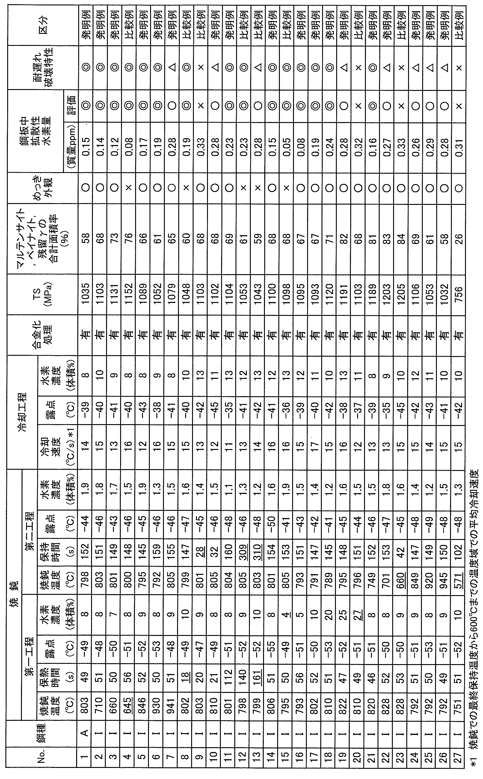
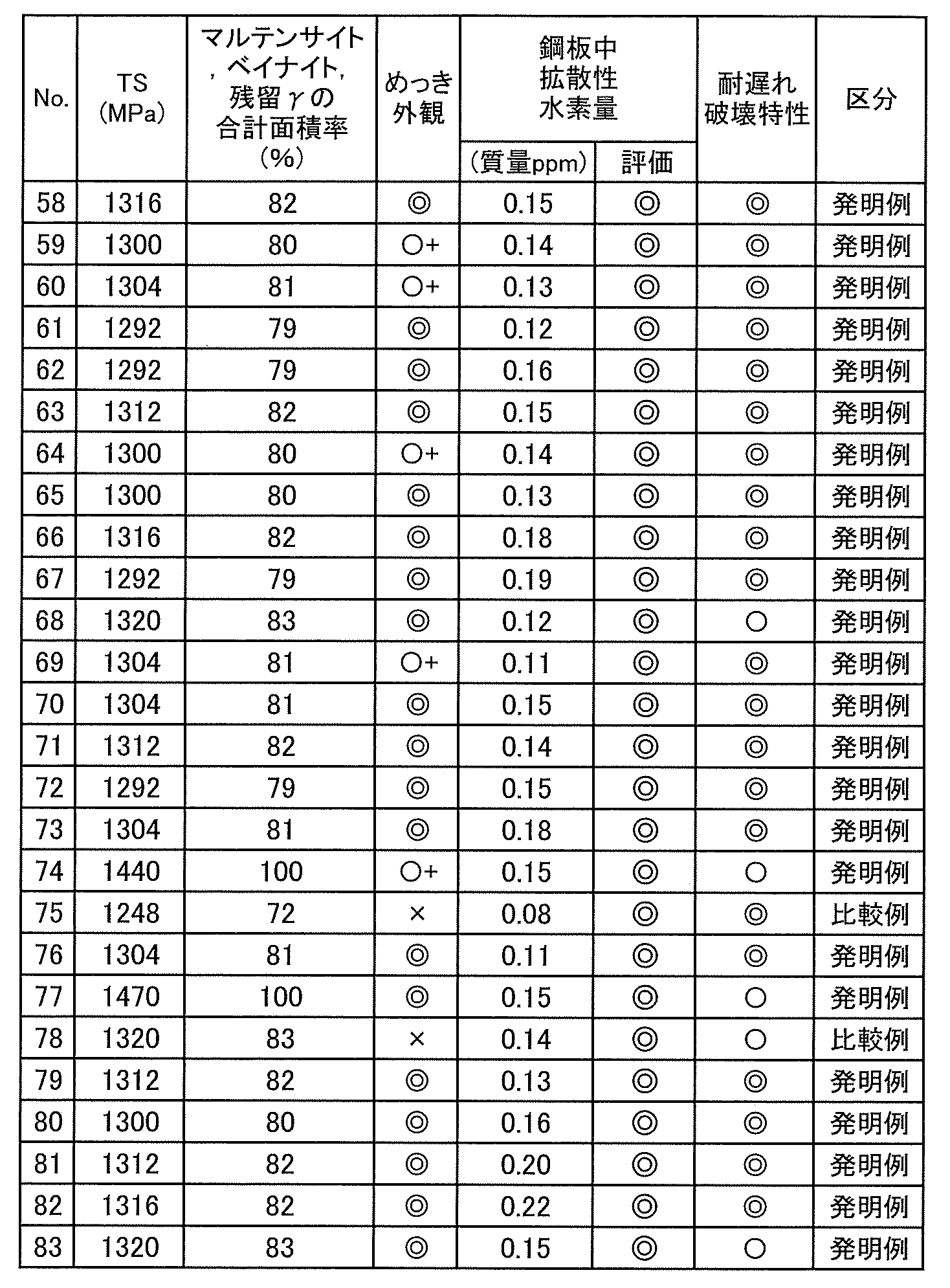
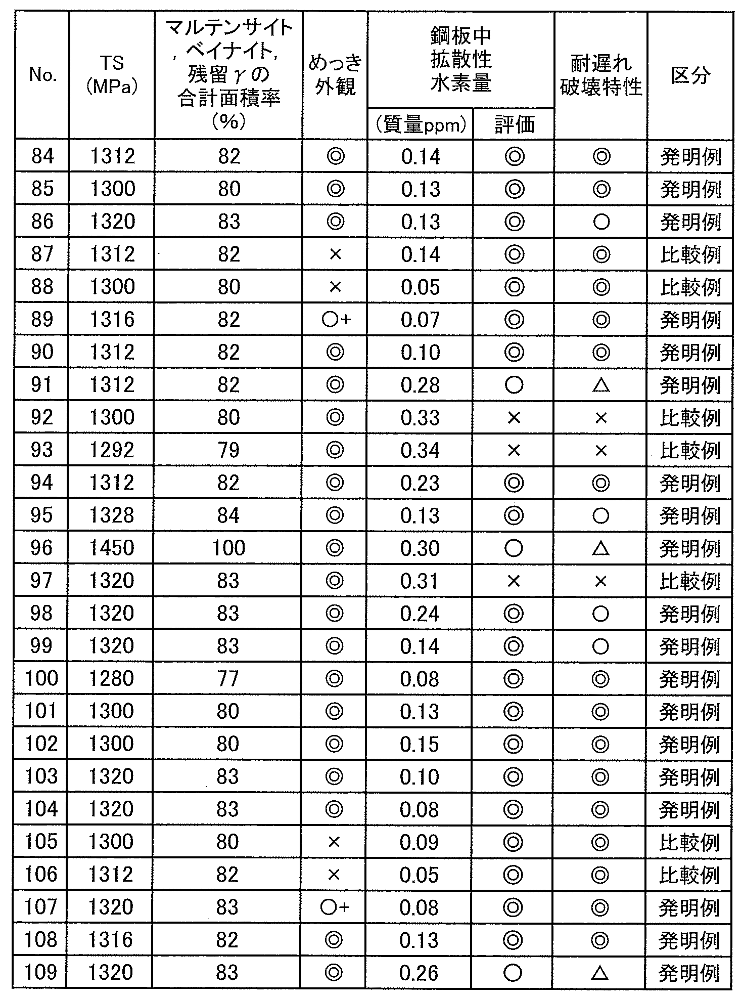
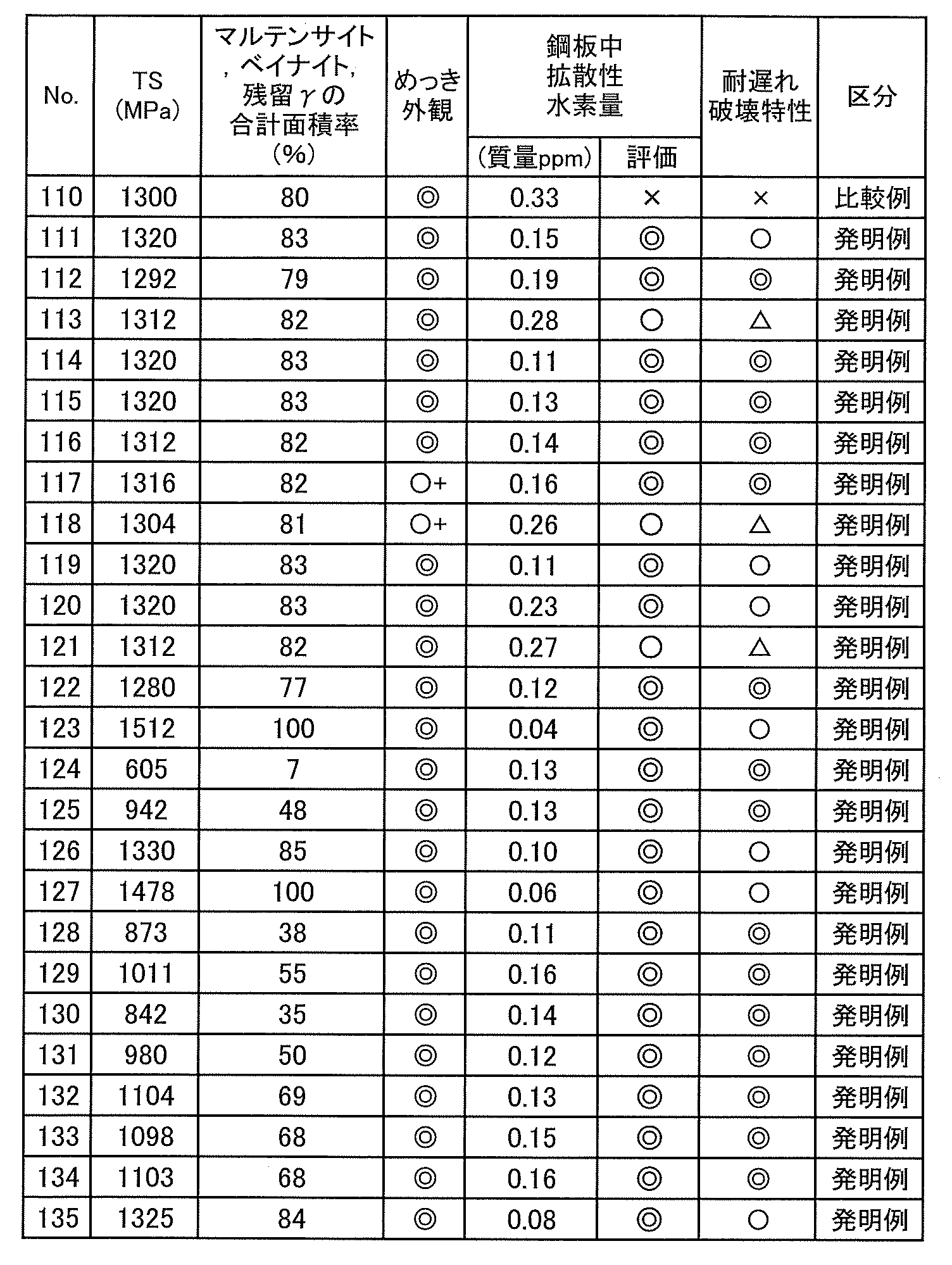
- the steel sheets were oxidized and annealed under the conditions shown in Tables 4 to 9, and then hot-dip galvanized (coating composition: Zn-0.2 mass% Al) was applied, and the coating weight per side was adjusted to about 50 g/ m2 by gas wiping, and then alloying was performed for some of the examples.
- No. 3 (Tables 4 and 5) is an example in which oxidation was performed at a constant temperature, and the holding time (treatment time) of the oxidation was 8 s.
- the oxidation was performed during temperature rise, and the temperature rise rate of this oxidation was in the range of 5 to 20°C/s.
- the amount of diffusible hydrogen in the steel sheets and the evaluation of the coating appearance and delayed fracture resistance were performed by the following measuring and evaluation methods.
- the results are shown in Tables 2 to 9 together with the production conditions.
- the "oxidation start temperature” is the entry strip temperature of the oxidation zone in the heating zone of the DFF annealing furnace
- the "oxidation end temperature” is the exit strip temperature of the oxidation zone
- the oxygen concentration is the oxygen concentration in the oxidation zone. Therefore, the range from the oxidation start temperature to the oxidation end temperature is the oxidation treatment temperature.
- the "oxidation temperature range” is the temperature range in which the steel sheet rises in temperature in the oxidation zone (the temperature range from the oxidation start temperature to the oxidation end temperature), and the “maximum steel sheet temperature reached” is the maximum temperature reached in the heating zone of the DFF annealing furnace. Therefore, when the "maximum steel sheet temperature reached" is higher than the “oxidation end temperature", it indicates that the steel sheet was further heated in a non-oxidizing atmosphere in the zone next to the oxidation zone (a zone that is not the oxidation zone).
- the total amount of released hydrogen from the analysis start temperature to 300°C was calculated as the amount of diffusible hydrogen in steel.
- a steel with a diffusible hydrogen amount of 0.25 mass ppm or less was evaluated as excellent " ⁇ "
- a steel with a diffusible hydrogen amount of more than 0.25 mass ppm and less than 0.30 mass ppm was evaluated as good " ⁇ ”. From experience, when the diffusible hydrogen amount in steel exceeds 0.30 mass ppm, the delayed fracture resistance property is often reduced, so a steel with a diffusible hydrogen amount of more than 0.30 mass ppm was evaluated as poor "X".
- Tensile Test A test piece was taken from the hot-dip galvanized steel sheet in the direction perpendicular to the rolling direction (so that the sheet width direction was the tensile direction). A tensile test was performed on this test piece in accordance with JIS Z2241 (2011) to measure the tensile strength (TS).
- the total area ratio of martensite, bainite and residual ⁇ in the base steel sheet structure was measured as follows. A sample was cut out so that the plate thickness cross section (L cross section) parallel to the rolling direction of the steel sheet was the observation surface, and the observation surface of the sample was polished with diamond paste, and then finish polished with alumina. Next, the observation surface of the sample was etched with 3 vol% nital to reveal the structure. The observation position was a quarter of the plate thickness position on this sample observation surface, and five fields of view were observed at a magnification of 3000 times using an SEM.
- the total area of martensite, bainite and residual ⁇ was obtained from the obtained structure image, and the area ratio of this total area divided by the measurement area was calculated for the five fields of view, and the average of these values was taken as the total area ratio of martensite, bainite and residual ⁇ .
- the discrimination of martensite, bainite, residual ⁇ and other microstructures was performed as follows.
- -Martensite There are two types of martensite: tempered martensite and fresh martensite. ...Tempered martensite Tempered martensite is a gray or dark gray area close to black in SEM photographs. Tempered martensite has a blocky form with boundaries at the interfaces with other structures such as prior gamma grain boundaries and ferrite.
- tempered martensite may contain other structures such as bainite inside and have a concave shape. Tempered martensite contains many carbides inside, but depending on the plane orientation, there may be only a small amount of carbides.
- Fresh martensite is the grey or white area in the SEM photograph. Fresh martensite is in the form of blocks, granules, plates, or films, and does not contain carbides.
- Bainite Bainite is the dark gray area in the SEM photograph. Bainite is in the form of a film, a plate, or a mass in which some or all of these adjacent areas are connected, and contains a small amount of carbide inside. Bainite also includes carbide that has been tempered after formation to coarsen the carbides. Residual gamma The retained ⁇ is a region that has the same color and morphology as the above-mentioned fresh martensite. Note that the retained ⁇ and fresh martensite cannot be distinguished by SEM.
- Ferrite Ferrite is the black area in the SEM photograph. Ferrite has a blocky morphology and contains almost no carbides. Bainitic ferrite contains almost no carbides inside and has similar mechanical properties to ferrite, so it belongs to the ferrite category. Ferrite may contain either granular or blocky fresh martensite, granular or blocky retained gamma, or both.
- Carbide is the white area in the SEM photograph. Carbide has a granular or film-like form.
- Carbide is formed finely inside ferrite, martensite, and bainite. Therefore, the area ratio of carbides is not excluded from the area ratio of each structure, but is included in the area ratio of each structure.
- nitrides such as TiN, carbonitrides such as (Nb, Ti ) (C, N), sulfides such as MnS and CaS, and oxides such as Al2O3 and SiO2 may also be contained in a total area ratio of about several percent. Since the area ratios of these are small, these area ratios are included in the area ratios of each structure containing them. In some cases, pearlite may also be contained. The area ratio of pearlite is calculated.
- the size and abundance of each tissue are not particularly limited, but as one embodiment of the present invention, the following sizes and abundances can be exemplified:
- the aspect ratio is the ratio of the length of the major axis to the length of the minor axis perpendicular to the major axis, the thickness is the length of the minor axis, and the circle equivalent diameter is the diameter when the area of each tissue is taken as the area of a circle.
- a rectangular test piece with a major axis length of 100 mm and a minor axis length of 20 mm was taken from the hot-dip galvanized steel sheet in the direction perpendicular to the rolling direction, and a punched hole with a diameter of 15 mm and a clearance of 12.5% was formed at the center of the major axis and minor axis of the test piece.
- the test piece was subjected to a tensile test, and the delayed fracture resistance was evaluated based on the presence or absence of delayed fracture from the punched hole.
- the time from taking the rectangular test piece from the hot-dip galvanized steel sheet to starting the delayed fracture tensile test was set to within 10 minutes.
- the loading time of the tensile test was set to a maximum of 100 hours, and the maximum stress at which no cracks (here, cracks mean fractures when tensile stress is applied) were generated after 100 hours of loading was defined as the limit stress, and the delayed fracture resistance was evaluated based on the ratio of the limit stress to the yield stress.
- the evaluation criteria for delayed fracture resistance were as follows: when the critical stress/yield stress was 1.10 or more, it was given an excellent " ⁇ ", when it was less than 1.10 and 1.05 or more, it was given a good " ⁇ ", when it was less than 1.05 and 1.00 or more, it was given a pass " ⁇ " (not good ( ⁇ )) and when it was less than 1.00, it was given a poor " ⁇ ". Note that the delayed fracture resistance evaluated in the delayed fracture test is generally lower (disadvantageous) for steel plates with higher strength.
- the hot-dip galvanized steel sheets of the present invention have a beautiful surface appearance with no uncoated areas, and also have excellent resistance to delayed fracture.
Landscapes
- Chemical & Material Sciences (AREA)
- Engineering & Computer Science (AREA)
- Materials Engineering (AREA)
- Mechanical Engineering (AREA)
- Metallurgy (AREA)
- Organic Chemistry (AREA)
- Thermal Sciences (AREA)
- Physics & Mathematics (AREA)
- Chemical Kinetics & Catalysis (AREA)
- Crystallography & Structural Chemistry (AREA)
- Oil, Petroleum & Natural Gas (AREA)
- Coating With Molten Metal (AREA)
- Heat Treatment Of Sheet Steel (AREA)
Abstract
Description
一般に、溶融亜鉛めっき鋼板は、熱延鋼板や冷延鋼板を母材として用い、この母材鋼板をCGLの焼鈍炉で再結晶焼鈍した後、溶融亜鉛めっきすることにより製造される。また、合金化溶融亜鉛めっき鋼板は、溶融亜鉛めっき後、さらに合金化処理することにより製造される。
特許文献1には、熱延鋼板を還元処理した後、H2濃度8~20%の雰囲気中において450~550℃で脱水素処理を行い、しかる後、溶融亜鉛めっきを行う技術が示されている。
また、特許文献2には、熱延鋼板を650~950℃の範囲で還元焼鈍した後、溶融亜鉛めっきを行う方法において、焼鈍炉内の焼鈍温度と水素濃度の関係が下記式(1)を満たすように制御することで鋼板中の水素量を低減する技術が示されている。
1≦H≦-0.05×RT+57.5 ・・・(1)
ここで、Hは炉内水素濃度であり、RTは焼鈍温度である。
されている。
log(PH2O/PH2)≦-1.55 ・・・(2)
-0.91≦log(PH2O/PH2)≦-0.635 ・・・(3)
また、特許文献3に示される技術は、焼鈍温度別に水蒸気分圧と水素分圧の比を変化させることで、Si、Mn、Al含有鋼のめっき性を改善し、良好な表面品質を得ようとするものであるが、炉内の水素濃度を10%以上に制御することが必要であり、鋼中に含有する水素濃度を低減することは考慮されておらず、このため高強度鋼板の耐遅れ破壊特性の改善は困難である。
本発明は、このような知見に基づきなされたもので、その要旨は以下のとおりである。
[1]連続焼鈍炉において鋼板を非酸化性雰囲気中で焼鈍した後、溶融亜鉛系めっきを施す溶融亜鉛系めっき鋼板の製造方法(但し、溶融亜鉛系めっき後に合金化処理する場合を含む)であって、
前記焼鈍は、
鋼板を露点-55℃以上+20℃以下、水素濃度5体積%以上25体積%以下の雰囲気中で650℃以上950℃以下の温度に20s以上150s以下の時間保持する第一工程と、
該第一工程を経た鋼板を、露点-50℃以上+20℃以下、水素濃度0.2体積%以上5.0体積%未満の雰囲気中で700℃以上950℃以下の温度に30s以上300s以下の時間保持する第二工程と、を有する、溶融亜鉛系めっき鋼板の製造方法。
[2]上記[1]の製造方法において、前記焼鈍を施す前の鋼板に、O2を1000体積ppm以上含む雰囲気中において400℃以上900℃以下の温度で酸化処理を施す、溶融亜鉛系めっき鋼板の製造方法。
[3]上記[2]の製造方法において、前記酸化処理を、前記焼鈍のために鋼板を昇温する過程で実施する、溶融亜鉛系めっき鋼板の製造方法。
[4]上記[3]の製造方法において、前記酸化処理を、前記焼鈍のために鋼板を昇温する過程で50℃以上の昇温範囲にわたって実施する、溶融亜鉛系めっき鋼板の製造方法。
[5]上記[1]~[4]のいずれかの製造方法において、前記焼鈍の第一工程の雰囲気は水素濃度が8体積%以上である、溶融亜鉛系めっき鋼板の製造方法。
[6]上記[1]~[5]のいずれかの製造方法において、前記焼鈍の第二工程の雰囲気は水素濃度が2.0体積%以上である、溶融亜鉛系めっき鋼板の製造方法。
[7]上記[1]~[6]のいずれかの製造方法において、製造される溶融亜鉛系めっき鋼板の下地鋼板中の水素濃度(但し、拡散性水素量)が0.30質量ppm以下である、溶融亜鉛系めっき鋼板の製造方法。
[8]上記[1]~[7]のいずれかの製造方法において、下地鋼板のSi含有量が0.1質量%以上である、溶融亜鉛系めっき鋼板の製造方法。
[9]上記[1]~[8]のいずれかの製造方法において、下地鋼板のマルテンサイト、ベイナイトおよび残留γの合計面積率が30%以上であり、引張強度が780MPa以上である、溶融亜鉛系めっき鋼板の製造方法。
[10]上記[1]~[8]のいずれかの製造方法において、下地鋼板のマルテンサイト、ベイナイトおよび残留γの合計面積率が50%以上であり、引張強度が980MPa以上である、溶融亜鉛系めっき鋼板の製造方法。
[11]上記[1]~[10]のいずれかの製造方法において、前記焼鈍を経た鋼板を、露点-20℃以下、水素濃度5体積%以上25体積%以下の雰囲気中で、前記焼鈍での最終保持温度から600℃までの温度域を平均冷却速度5℃/s以上で冷却し、さらに150℃以上600℃未満の温度まで冷却した後、必要に応じて加熱し、溶融亜鉛系めっき浴に浸漬して溶融亜鉛系めっきを施す、溶融亜鉛系めっき鋼板の製造方法。
また、本発明が適用される溶融亜鉛系めっき鋼板の種類としては、亜鉛を主成分とするめっき層を有するめっき鋼板であれば特に限定されず、溶融亜鉛めっき鋼板(GI)および合金化溶融亜鉛めっき鋼板(GA)以外に、溶融亜鉛-アルミニウム合金めっき鋼板、溶融亜鉛-アルミニウム-シリコン合金めっき鋼板、溶融亜鉛-アルミニウム-マグネシウム合金めっき鋼板などが含まれ、またそれぞれの詳細なめっき組成も制限はない。
なお、以下の説明において、鋼板(下地鋼板、母材鋼板とも記す。)の成分組成の各元素の含有量、めっき浴の成分組成の元素の含有量およびめっき層の合金化度の単位として記載した「%」はいずれも「質量%」であり、また、焼鈍および冷却時の雰囲気の水素濃度の単位として記載した「%」はいずれも「体積%」である。また、鋼板が「高強度」であるとは、JIS Z2241(2011)に準拠して測定した鋼板の引張強さTSが590MPa以上であることを意味する。
なお、溶融亜鉛系めっき鋼板の母材となる鋼板組織およびその成分組成については、後に詳述する。
本発明において、酸化処理とそれに続く非酸化性雰囲気における焼鈍は、通常、入側から順に酸化帯(酸化処理のための帯域)、還元帯(焼鈍の第一工程のための帯域)、均熱帯(焼鈍の第二工程のための帯域)、冷却帯を有する連続焼鈍炉で行われる。
ここで、酸化処理は、必須工程では無く、必要に応じて適宜行うことができる。
・酸化処理
酸化処理では、O2を1000体積ppm以上含む雰囲気中で鋼板温度を400℃以上900℃以下に制御することで、鋼板表層に酸化Feを形成する。酸化処理の雰囲気は、O2以外にN2、CO、CO2、H2O、NOxのうちの1種または2種以上を含んでもよい。N2は不活性ガス、COは酸化と還元の調整用のガス、CO2は不活性ガス、H2Oは酸化と還元の調整用のガスとして含有させることができる。また、CO、CO2、H2OおよびNOxは燃料ガス、焼鈍する鋼板成分由来のガスや大気中の不純物ガス、もしくは燃料の燃焼ガスとして含有させることができる。
酸化処理を行う雰囲気中のO2濃度を1000体積ppm以上とすることで、鋼板の酸化が促進される。O2濃度が1000体積ppm未満では、鋼板の酸化が不十分となり、Si、Mnの酸化物が形成されてめっき性が低下する場合がある。
酸化処理の雰囲気は、その他に使用するガスによってN2、CO、CO2、H2O、NOx等を含むことがあり、それらの比率は特に限定されない。また、酸化処理によって、さらに美麗な表面外観を得ることができるものの、酸化処理が無くても耐遅れ破壊特性に優れた溶融亜鉛めっき鋼板を得ることが可能であるため、この工程は必須要件では無い。
一方、鋼板温度が900℃を超えると、鋼板の酸化量が過剰となり、続く還元焼鈍(第一工程)で還元が完了せず、残存した酸化鉄がめっき性を阻害する場合がある。このため、酸化処理は400℃以上900℃以下で実施することが好ましい。ここで、酸化処理を400℃以上900℃以下で実施するとは、酸化処理温度が少なくとも400~900℃の範囲内にあり、且つ900℃を超えないことを意味し、したがって、この条件内において、400℃未満で酸化処理の一部が行われてもよい(例えば、300℃→700℃の昇温過程で酸化処理が行われる場合など)。
この酸化処理は処理時間1~30sの範囲で実施することが好ましい。すなわち、十分な酸化量を確保してめっき性を改善する観点から、処理時間は1s以上とすることが好ましく、2s以上とすることがより好ましく、3s以上とすることがさらに好ましい。一方、過剰な酸化を防止してピックアップを抑制する観点からは、処理時間は30s以下とすることが好ましく、20s以下とすることがより好ましく、15s以下とすることがさらに好ましい。
焼鈍の第一工程では、鋼板を露点-55℃以上+20℃以下、水素濃度5%以上25%以下の酸化Feが還元される雰囲気中で650℃以上950℃以下の温度に20s以上150s以下の時間保持する。
鋼板表層に存在する自然酸化Feを、焼鈍の第一工程において還元雰囲気中で還元し、めっき性を確保する。続く低水素濃度雰囲気による第二工程では還元はほとんど進行しないため、この第一工程で酸化Feの還元を完了する必要がある。この第一工程は、良好なめっき外観を得るために必須である。
また、酸化処理をした場合、意図的に形成された酸化Feを、この還元焼鈍の第一工程において還元雰囲気中で還元し、鋼板表層に還元鉄層を形成することで、Si、Mnが鋼板表層に拡散して酸化するのを防ぎ、外観をさらに美麗にすることができる。同様に、続く低水素濃度雰囲気による第二工程では還元はほとんど進行しないため、この第一工程で酸化Feの還元を完了する必要がある。
第一工程の雰囲気の露点は、+20℃以下で鋼板表層の酸化Feを還元することができ、所定の焼鈍時間の範囲においてはSiやMnの選択酸化も抑制できる。露点を-55℃未満とするには露点を低下させるための特殊な設備が必要となり、コストが増加する。一方、露点が+20℃を超えると炉内の露点分布が大きくなって露点制御が困難となるとともに、炉体への影響が懸念される。このため露点は-55℃以上+20℃以下とする。
また、SiやMnの選択酸化が進行して表面品質やめっき密着性が劣化する。なお、鋼中水素量は保持時間20s程度で飽和し、保持時間の影響は大きくない。このため、第一工程における650℃以上950℃以下での保持時間は20s以上150s以下とする。
焼鈍の第二工程では、第一工程を経た鋼板を、露点-50℃以上+20℃以下、水素濃度0.2%以上5.0%未満の雰囲気中で700℃以上950℃以下の温度に30s以上300s以下の時間保持する。この第二工程では、第一工程で還元が完了した鋼板を低水素雰囲気に維持することで、鋼板から水素を放出させる。
第二工程での鋼板の焼鈍温度が700℃未満では脱水素が促進されない。一方、焼鈍温度が950℃を超えると炉体への影響が大きい。このため鋼板の焼鈍温度は700℃以上950℃以下とする。鋼中水素量を低減する観点から第二工程の焼鈍温度は860℃以下とすることが好ましく、830℃以下とすることがさらに好ましい。また、引張強度が780MPa以上の高強度鋼板を得るためには、マルテンサイト、ベイナイトおよび残留γの合計面積率を所定量確保する必要があり、第二工程での焼鈍温度は780℃以上とすることが好ましい。
また、第二工程では、水素濃度が低いほど第一工程で鋼板中に固溶した水素が多く放出されるが、炉内の水素濃度を均一に0.2%未満に制御するのは困難であり、水素濃度が低い部分で鋼板が再酸化する懸念があるため、水素濃度は0.2%以上とする。一方、水素濃度が5.0%以上では、鋼中水素量を十分に低減できないので、水素濃度は5.0%未満とする。また、上記の観点から水素濃度は1.0%以上が好ましく、2.0%以上がより好ましい。同じく水素濃度は4.0%以下がより好ましい。
本発明では、鋼板表面に自然に存在する酸化Feまたは酸化処理で生成させた酸化Feを焼鈍の第一工程で還元するために高濃度の水素が必要であり、その分、鋼中に水素が多く固溶するため、還元と脱水素のバランスが重要であり、そのために焼鈍の第一工程と第二工程の条件を上述したように最適化する必要がある。
焼鈍の第一工程と第二工程で水素濃度を変化させる方法は特に規定しないが、炉を分割し、シールロールを介して接続された炉を使用し、それぞれの炉に投入するガスの水素濃度、露点を制御することにより、第一工程と第二工程の雰囲気を個別に容易に制御することが可能である。本発明においては、分離された2つ以上の異なる雰囲気を制御可能な連続焼鈍炉を用いて鋼板を焼鈍することが好ましい。
焼鈍(第二工程)が完了した鋼板を、露点-20℃以下、水素濃度5%以上25%以下の雰囲気中で、前記焼鈍での最終保持温度から600℃までの温度域を平均冷却速度5℃/s以上で冷却し、さらに150℃以上600℃未満の温度まで冷却することが好ましい。その後、必要に応じて加熱した後、溶融亜鉛系めっき浴に浸漬して溶融亜鉛系めっきを行う。
焼鈍後の最終保持温度から600℃までの温度域を平均冷却速度5℃/s以上で冷却することにより、所望の鋼板強度が得られ、また、雰囲気中の水素が冷却中に鋼板に侵入することを抑制することができる。平均冷却速度が5℃/s未満では、鋼板強度が低下しやすく、また、雰囲気中の水素が鋼板に侵入して耐遅れ破壊特性が低下しやすくなる。ここで、焼鈍の第二工程における最終保持温度は、前記焼鈍の第二工程の焼鈍温度、水素濃度、露点、保持時間の要件を満たす範囲で焼鈍を行った鋼板が前記要件の少なくとも一つを外れる時の温度を指す。
また、上記の平均冷却速度(℃/s)は、冷却開始温度(上記最終保持温度)(℃)と冷却終了温度(600℃)との差を、冷却時間(s)で割ることにより得られる。
また、露点を-20℃以下とすることで、低温で鋼板が再酸化してめっき性が低下することを抑制することができる。すなわち、露点が-20℃を超えると、低温で鋼板が再酸化してめっき性が低下しやすい。
溶融亜鉛系めっきの条件は特に限定されず、一般的な条件で行えばよい。すなわち、好ましくは上述したような条件で150℃以上600℃未満の温度まで冷却した後、必要に応じてめっき浴温度程度まで加熱した鋼板を溶融亜鉛系めっき浴中に浸漬してめっきする。通常、GAやGIの場合には、めっき浴はZnとAlおよび不可避的不純物からなり、その成分は特に規定しないが、一般的には浴中Al濃度は0.05%以上0.190%以下程度である。浴中Al濃度が0.05%未満ではボトムドロスの発生が増加し、ドロスが鋼板に付着して欠陥になりやすい。一方、0.190%を超えるとトップドロスが増加し、やはりドロスが鋼板に付着して欠陥になりやすく、また、Alの添加によるコストアップにつながる。また、溶融亜鉛系めっき浴温度は通常の440~500℃程度である。
溶融亜鉛系めっき後に合金化処理を行う場合、合金化処理後のめっき層の合金化度は特に制限はないが、一般的には7~15%程度の合金化度が好ましい。合金化度が7%未満ではη相が残存してプレス成形性が低下しやすく、一方、15%を超えるとめっき密着性が低下しやすい。
母材鋼板は、冷延鋼板、熱延鋼板のいずれでもよい。また、耐遅れ破壊特性は、高強度鋼板において問題となる特性であるので、鋼板は引張強さTSが590MPa以上、好ましくは780MPa以上、さらに好ましくは980MPa以上の高強度鋼板であることが好ましい。
母材鋼板の成分については、通常の冷延鋼板や熱延鋼板が有する組成範囲であればよく、特に制限されるものではないが、以下のような成分組成とすることが好ましい。
また、鋼板の板厚は特に限定されないが、一般には0.5~3.2mm程度である。
Cは、鋼組織としてマルテンサイトなどを形成することで加工性を向上させる効果があるが、良好な溶接性を得るため、C含有量は0.8%以下とすることが好ましく、0.3%以下とすることがより好ましい。C含有量の下限は特にないが、良好な加工性を得るためには、C含有量は0.03%以上とすることが好ましく、0.05%以上とすることがより好ましい。
Siは、加工性を大きく損なうことなく、固溶により鋼の強度を高める効果(固溶強化能)が大きいため、鋼板の高強度化を達成するのに有効な元素である。一方で、Siは溶接部における耐抵抗溶接割れ特性に悪影響を及ぼす元素でもある。Siを鋼板の高強度化を図るために含有する場合には、0.1%以上の含有が好ましい。
一方、Si含有量が3.0%を超えると、熱間圧延性および冷間圧延性が大きく低下し、生産性に悪影響を及ぼしたり、鋼板自体の延性の低下を招いたりするおそれがある。このためSiは3.0%以下の範囲で含有ることが好ましい。また、そのような観点から、Si含有量は2.5%以下がより好ましく、2.0%以下が特に好ましい。
Mnは、鋼を固溶強化して高強度化するとともに、焼入性を高め、残留γ、ベイナイトおよびマルテンサイトの生成を促進する効果を有する元素である。このような効果は、Mnを1.3%以上含有することで発現する。このため、Mn含有量は1.3%以上とすることが好ましく、1.8%以上とすることがより好ましい。
一方、Mn含有量が3.5%以下であれば、コストの上昇を招かずに上記効果が得られる。このためMn含有量は3.5%以下とすることが好ましく、3.3%以下とすることがより好ましい。
P含有量を抑えることで、溶接性の低下を防ぐことができ、さらにPが粒界に偏析することを防止し、延性、曲げ性および靭性が劣化することを防ぐことができる。また、Pを多量に含有すると、フェライト変態を促進することで結晶粒径も大きくなってしまう。そのため、P含有量は0.1%以下とすることが好ましい。P含有量の下限は特に限定されないが、通常、生産技術上の制約から0.001%以上とすることが好ましい。
S含有量は極力低減することが好ましい。S含有量を抑えることで、溶接性の低下を防ぐとともに、熱間圧延時の延性の低下を防いで熱間割れを抑制し、表面性状を著しく向上することができる。さらに、S含有量を抑えることで、不純物元素として粗大な硫化物を形成することによる鋼板の耐遅れ破壊特性、延性、曲げ性、伸びフランジ性の低下を防ぐことができる。Sによる問題はS含有量が0.03%を超えると顕著となるので、S含有量は0.03%以下とすることが好ましく、0.02%以下とすることがより好ましい。耐遅れ破壊特性を改善する観点からはS含有量は0.01%以下とすることが好ましく、0.003%以下とすることがさらに好ましい。S含有量の下限は特に限定されないが、通常、生産技術上の制約から0.0001%以上とすることが好ましい。
N含有量を0.010%以下とすることにより、高温下においてNがTi,Nb,Vと粗大な窒化物を形成することでTi,Nb,V添加による鋼板の高強度化の効果が損なわれることを防ぐことができる。また、N含有量を0.010%以下とすることで、靭性の低下も防ぐことができる。さらに、N含有量を0.010%以下とすることで、熱間圧延中にスラブ割れ、表面疵が発生することを防ぐことができる。このためN含有量は0.010%以下とすることが好ましく、0.005%以下とすることがより好ましく、0.003%以下とすることがさらに好ましく、0.002%以下とすることが特に好ましい。N含有量の下限は特に限定されないが、通常、生産技術上の制約から0.0005%以上とすることが好ましい。
Alは熱力学的に最も酸化しやすいため、SiおよびMnに先だって酸化し、SiおよびMnの鋼板最表層での酸化を抑制し、SiおよびMnの鋼板内部での酸化を促進する効果がある。この効果は、Al含有量が0.01%以上で得られる。
一方、Al含有量が0.1%を超えるとコストアップになる。したがって、Alを含有する場合、Al含有量は0.1%以下とすることが好ましい。
Al含有量の下限は特に限定されないが、同様に不純物レベルのAlを除去することもコストアップに繋がるため、0.001%以上とすることが好ましい。また、上記のように、Al含有量は0.01%以上とすることが好ましい。
Bは鋼の焼入れ性を向上させるのに有効な元素である。焼入れ性を向上するためには、B含有量は0.0003%以上とすることが好ましく、0.0005%以上とすることがより好ましい。しかし、Bを過度に含有すると成形性が低下するため、B含有量は0.005%以下とすることが好ましい。
Tiは鋼の析出強化に有効な元素である。Tiの下限は特に限定されないが、強度調整の効果を得るためには、0.005%以上とすることが好ましい。しかし、Tiを過度に添加すると、硬質相が過大となり、成形性が低下するため、Tiを含有する場合、Ti含有量は0.2%以下とすることが好ましく、0.05%以下とすることがより好ましい。
Crは、0.005%以上含有することで焼き入れ性が向上し、強度と延性のバランスを向上させることができるが、コストアップを防ぐ観点から、Cr含有量は1.0%以下とすることが好ましい。
Nbは、0.005%以上含有することで強度向上の効果が得られるが、コストアップを防ぐ観点から、Nb量は0.20%以下とすることが好ましい。
Moは、0.005%以上含有することで強度調整の効果が得られ、特にMo量が0.05%以上でその効果が高まるが、コストアップを防ぐ観点から、Mo量は1.0%以下とすることが好ましい。
Cuは、0.005%以上含有することで残留γ相の形成を促進することができるが、コストアップを防ぐ観点から、Cuを含有する場合、Cu含有量は1.0%以下とすることが好ましい。
Niは、0.005%以上含有することで残留γ相の形成を促進することができるが、コストアップを防ぐ観点から、Niを含有する場合、Ni含有量は1.0%以下とすることが好ましい。
Sbは、鋼板表面の窒化、酸化、あるいは酸化により生じる鋼板表面の数十ミクロン領域の脱炭を抑制する観点から含有させることができる。Sbは、鋼板表面の窒化および酸化を抑制することで、鋼板表面においてマルテンサイトの生成量が減少するのを防止し、鋼板の疲労特性および表面品質を改善する。このような効果を得るために、Sb含有量は0.001%以上とすることが好ましい。一方、良好な靭性を得るためには、Sb含有量は0.20%以下とすることが好ましい。
Vは、0.005%以上含有することで強度向上の効果が得られるが、コストアップを防ぐ観点から、Vを含有する場合、V含有量は0.5%以下とすることが好ましい。
Taは、0.001%以上含有することで強度向上の効果が得られるが、コストアップを防ぐ観点から、Taを含有する場合、Ta含有量は0.1%以下とすることが好ましい。
Wは、0.005%以上含有することで強度向上の効果が得られるが、コストアップを防ぐ観点から、Wを含有する場合、W含有量は0.5%以下とすることが好ましい。
Zrは、0.0005%以上含有することで強度向上の効果が得られるが、コストアップを防ぐ観点から、Zrを含有する場合、Zr含有量は0.1%以下とすることが好ましい。
Snは、脱窒、脱硼等を抑制して鋼の強度低下抑制に有効な元素であり、このような効果を得るには0.002%以上含有することが好ましい。
一方、良好な耐衝撃性を得るために、Snを含有する場合、Sn含有量は0.20%以下とすることが好ましい。
Caは、0.0005%以上含有することで硫化物の形態を制御し、延性、靭性を向上させることができるが、良好な延性を得る観点から、Caを含有する場合、Ca含有量は0.005%以下とすることが好ましい。
Mgは、0.0005%以上含有することで硫化物の形態を制御し、延性、靭性を向上させることができるが、コストアップを防ぐ観点から、Mgを含有する場合、Mg含有量は0.005%以下とすることが好ましい。
REMは、0.0005%以上含有することで硫化物の形態を制御し、延性、靭性を向上させることができるが、良好な靭性を得る観点から、REMを含有する場合、REM含有量は0.005%以下とす
ることが好ましい。
すなわち、マルテンサイト、ベイナイトおよび残留γ(残留オーステナイト)の合計面積率を30%以上とすることが好ましく、これにより、引張強度が780MPa以上である母材鋼板が得られる。
また、マルテンサイト、ベイナイトおよび残留γの合計面積率を50%以上とすることにより、引張強度が980MPa以上である母材鋼板が得られる。
本発明により製造される溶融亜鉛系めっき鋼板は、下地鋼板中の水素濃度が低く優れた耐遅れ破壊特性を有するが、特に、下地鋼板中の水素濃度(但し、拡散性水素量)が0.30質量ppm以下であることが好ましく、0.25質量ppm以下であることが特に好ましい。ここで、拡散性水素量とは、後述する実施例に記載の方法で測定される鋼板中の水素量である。
オールラジアントチューブ(ART)型焼鈍炉を有するCGLにおいて、鋼板を表2および表3に示す条件で焼鈍した後、溶融亜鉛めっき(めっき組成:Zn-0.2mass%Al)を施し、ガスワイピングで片面当たりのめっき目付量を約50g/m2に調整し、次いで、一部の実施例については合金化処理を行った。
上記実施例とは別に、DFF型焼鈍炉を有するCGLにおいて、鋼板を表4~9に示す条件で酸化処理および焼鈍した後、溶融亜鉛めっき(めっき組成:Zn-0.2mass%Al)を施し、ガスワイピングで片面当たりのめっき目付量を約50g/m2に調整し、次いで、一部の実施例については合金化処理を行った。なお、No.3(表4および表5)は、一定温度で酸化処理を行った実施例であり、酸化処理の保持時間(処理時間)は8sとした。その他の実施例は、酸化処理を昇温中に行ったものであり、この酸化処理の昇温速度は5~20℃/sの範囲とした。
ここで、表4~9の実施例の酸化処理において、「酸化開始温度」はDFF焼鈍炉の加熱帯における酸化帯の入側板温、「酸化終了温度」は同じく酸化帯の出側板温、酸素濃度は酸化帯の酸素濃度であり、したがって、酸化開始温度~酸化終了温度の範囲が酸化処理温度である。また、「酸化温度域」とは酸化帯で鋼板が昇温する温度幅(酸化開始温度から酸化終了温度までの温度幅)のことであり、「鋼板最高到達温度」とはDFF焼鈍炉の加熱帯での最高到達温度である。したがって、「酸化終了温度」よりも「鋼板最高到達温度」が高い場合は、酸化帯の次の帯域(酸化帯ではない帯域)でも非酸化性の雰囲気でさらに加熱されたことを示している。
溶融亜鉛系めっき鋼板の幅中央部から、長軸長さ30mm、短軸長さ5mmの短冊状の試験片を採取し、その試験片のめっき層をリューターで除去し、直ちに、昇温脱離分析装置を用いて分析開始温度25℃、分析終了温度300℃、昇温速度200℃/時間の条件で水素分析し、各温度において試験片表面から放出される水素量である放出水素量(質量ppm/min)を測定した。分析開始温度から300℃までの放出水素量の合計を鋼中拡散性水素量として算出した。ここで、鋼中拡散性水素量が0.25質量ppm以下のものを優良“◎”、0.25質量ppm超0.30質量ppm以下のものを良好“〇”とした。経験上、鋼中拡散性水素量が0.30質量ppmを超えると、耐遅れ破壊特性が低下することが多いことから、0.30質量ppm超のものを不良“×”とした。
溶融亜鉛系めっき鋼板のめっき外観を目視観察し、模様や凹凸が認められないものを優良“◎”、模様や凹凸が認められるが、不めっき欠陥やロールへのピックアップによる押し疵がないものを良好“○+”、不めっき欠陥やロールへのピックアップによる押し疵があるものを不良“×”とした。また、不めっき欠陥やロールへのピックアップによる押し疵はないが、その兆候として通板方向に対してVマーク状に生じるウロコ模様が生じたものについては、良好(○+)ではないものの合格“〇”とした。
溶融亜鉛系めっき鋼板の圧延直角方向から(板幅方向が引張方向になるように)試験片を採取し、この試験片についてJIS Z2241(2011)に準拠した引張試験を行い、引張強度(TS)を測定した。
母材鋼板組織中のマルテンサイト、ベイナイトおよび残留γの合計面積率を、以下のようにして測定した。鋼板の圧延方向に平行な板厚断面(L断面)が観察面となるよう試料を切り出し、この試料の観察面にダイヤモンドペーストによる研磨を施した後、アルミナを用いて仕上げ研磨を施した。次いで、試料の観察面を3vol%ナイタールでエッチングし、組織を現出させた。この試料観察面における板厚の1/4位置を観察位置とし、SEMにより倍率:3000倍で5視野観察した。得られた組織画像からマルテンサイト、ベイナイトおよび残留γの合計面積を求め、この合計面積を測定面積で除した面積率を5視野分算出し、それらの値を平均したものをマルテンサイト、ベイナイトおよび残留γの合計面積率とした。マルテンサイト、ベイナイト、残留γならびにその他のミクロ組織の判別は、以下のように行った。
・マルテンサイト
マルテンサイトには、焼戻しマルテンサイトとフレッシュマルテンサイトの2種類がある。
・・焼戻しマルテンサイト
焼戻しマルテンサイトは、SEM写真で灰色もしくは黒色に近い濃い灰色の領域である。焼戻しマルテンサイトは、旧γ粒界やフェライト等の他の組織との界面を境界とした塊状の形態を呈する。ただし、焼戻しマルテンサイトは、内部にベイナイト等の他の組織を内包して凹形状を呈する場合がある。焼戻しマルテンサイトは内部に炭化物を多く含むが、面方位に依存して炭化物が少量の場合もある。
・・フレッシュマルテンサイト
フレッシュマルテンサイトは、SEM写真で灰色もしくは白色の領域である。フレッシュマルテンサイトは塊状、粒状、プレート状、フィルム状であり、炭化物を含まない。
・ベイナイト
ベイナイトは、SEM写真で濃い灰色の領域である。ベイナイトは、フィルム状、プレート状、これらの隣接領域の一部または全部が連結した塊状のいずれかの形態を呈し、内部に炭化物を僅かに含む。ベイナイトは、生成後に焼戻し処理が施されて炭化物が粗大化したものも含む。
・残留γ
残留γは、上記のフレッシュマルテンサイトと同一の色と形態を呈する領域である。なお、SEMでは残留γとフレッシュマルテンサイトは識別できない。
・フェライト
フェライトは、SEM写真で黒色の領域である。フェライトは、塊状の形態を呈し、炭化物を殆ど含まない。ベイニティックフェライトは、内部に炭化物を殆ど含まず、フェライトと類似の機械的性質を有するので、フェライトに属する。フェライトは、内部に粒状もしくは塊状のフレッシュマルテンサイト、粒状もしくは塊状の残留γのいずれかもしくは両者を含む場合がある。
・炭化物
炭化物は、SEM写真で白色の領域である。炭化物は、粒状やフィルム状の形態を呈する。炭化物は、主にフェライト、マルテンサイト、ベイナイトの内部に微細に生成する。
したがって、炭化物の面積率は各組織の面積率から除外せず、各組織の面積率に含める。
・上記以外の組織
上記以外に、TiN等の窒化物、(Nb,Ti)(C,N)等の炭窒化物、MnS、CaS等の硫化物、Al2O3,SiO2等の酸化物も合計面積率で数%程度含む場合がある。これらの面積率は小さいので、これらの面積率はこれらを含む各組織の面積率に含める。さらにパーライトを含む場合もある。パーライトはその面積率を算出する。
・焼戻しマルテンサイト
アスペクト比≦8、円相当径≦30μm
組織内部の炭化物の分布密度:0.10~12個/μm2
・フレッシュマルテンサイトおよび残留γ
塊状:アスペクト比≦8、円相当径:3~30μm
粒状:アスペクト比≦8、円相当径:0.40μm以上、3μm未満
プレート状もしくはフィルム状:アスペクト比8超、厚さ:0.10~8μm
・ベイナイト
フィルム状もしくはプレート状:アスペクト比8超、厚さ≦8μm
塊状:アスペクト比≦8、円相当径≦30μm
組織内部の炭化物の分布密度:いずれの形態においても0.10~6個/μm2
・炭化物
粒状:アスペクト比≦8、円相当径:0.01μm以上、0.40μm未満
フィルム状:アスペクト比8超、円相当径:0.01μm以上、0.10μm未満
溶融亜鉛系めっき鋼板の圧延直角方向から、長軸長さ100mm、短軸長さ20mmの短冊状の試験片を採取し、この試験片の長軸・短軸の中心位置に直径15mm、クリアランス12.5%で打抜き穴を形成した。この試験片を引張試験に供し、打抜き穴からの遅れ破壊発生の有無により耐遅れ破壊特性を評価した。経時変化による鋼中の拡散性水素の放出を防ぐために、溶融亜鉛系めっき鋼板から短冊状の試験片を採取してから遅れ破壊の引張試験(引張速度10mm/分)を開始するまでの時間を10分以内とした。引張試験の負荷時間は最大100時間とし、100時間負荷後に亀裂(ここで、亀裂とは引張応力負荷時の破断を意味する)が生じなかった最大応力を限界応力とし、限界応力と降伏応力の比で耐遅れ破壊特性を評価した。耐遅れ破壊特性の評価基準としては、限界応力/降伏応力が1.10以上の場合を優良“◎”、1.10未満1.05以上の場合を良好“〇”、1.05未満1.00以上の場合を良好(○)ではないものの合格“△”とし、1.00未満の場合を不良“×”とした。なお、遅れ破壊試験で評価される耐遅れ破壊特性は、一般的に強度の高い鋼板のほうが低く(不利に)なる。





Claims (11)
- 連続焼鈍炉において鋼板を非酸化性雰囲気中で焼鈍した後、溶融亜鉛系めっきを施す溶融亜鉛系めっき鋼板の製造方法(但し、溶融亜鉛系めっき後に合金化処理する場合を含む)であって、
前記焼鈍は、
鋼板を露点-55℃以上+20℃以下、水素濃度5体積%以上25体積%以下の雰囲気中で650℃以上950℃以下の温度に20s以上150s以下の時間保持する第一工程と、
該第一工程を経た鋼板を、露点-50℃以上+20℃以下、水素濃度0.2体積%以上5.0体積%未満の雰囲気中で700℃以上950℃以下の温度に30s以上300s以下の時間保持する第二工程と、を有する、溶融亜鉛系めっき鋼板の製造方法。 - 前記焼鈍を施す前の鋼板に、O2を1000体積ppm以上含む雰囲気中において400℃以上900℃以下の温度で酸化処理を施す、請求項1に記載の溶融亜鉛系めっき鋼板の製造方法。
- 前記酸化処理を、前記焼鈍のために鋼板を昇温する過程で実施する、請求項2に記載の溶融亜鉛系めっき鋼板の製造方法。
- 前記酸化処理を、前記焼鈍のために鋼板を昇温する過程で50℃以上の昇温範囲にわたって実施する、請求項3に記載の溶融亜鉛系めっき鋼板の製造方法。
- 前記焼鈍の第一工程の雰囲気は水素濃度が8体積%以上である、請求項1~4のいずれかに記載の溶融亜鉛系めっき鋼板の製造方法。
- 前記焼鈍の第二工程の雰囲気は水素濃度が2.0体積%以上である、請求項1~5のいずれかに記載の溶融亜鉛系めっき鋼板の製造方法。
- 製造される溶融亜鉛系めっき鋼板の下地鋼板中の水素濃度(但し、拡散性水素量)が0.30質量ppm以下である、請求項1~6のいずれかに記載の溶融亜鉛系めっき鋼板の製造方法。
- 下地鋼板のSi含有量が0.1質量%以上である、請求項1~7のいずれかに記載の溶融亜鉛系めっき鋼板の製造方法。
- 下地鋼板のマルテンサイト、ベイナイトおよび残留γの合計面積率が30%以上であり、引張強度が780MPa以上である、請求項1~8のいずれかに記載の溶融亜鉛系めっき鋼板の製造方法。
- 下地鋼板のマルテンサイト、ベイナイトおよび残留γの合計面積率が50%以上であり、引張強度が980MPa以上である、請求項1~8のいずれかに記載の溶融亜鉛系めっき鋼板の製造方法。
- 前記焼鈍を経た鋼板を、露点-20℃以下、水素濃度5体積%以上25体積%以下の雰囲気中で、前記焼鈍での最終保持温度から600℃までの温度域を平均冷却速度5℃/s以上で冷却し、さらに150℃以上600℃未満の温度まで冷却した後、必要に応じて加熱し、溶融亜鉛系めっき浴に浸漬して溶融亜鉛系めっきを施す、請求項1~10のいずれかに記載の溶融亜鉛系めっき鋼板の製造方法。
Priority Applications (5)
| Application Number | Priority Date | Filing Date | Title |
|---|---|---|---|
| CN202380097239.2A CN121039302A (zh) | 2023-04-28 | 2023-04-28 | 热镀锌系钢板的制造方法 |
| PCT/JP2023/016784 WO2024224581A1 (ja) | 2023-04-28 | 2023-04-28 | 溶融亜鉛系めっき鋼板の製造方法 |
| KR1020257034640A KR20250168368A (ko) | 2023-04-28 | 2023-04-28 | 용융 아연계 도금 강판의 제조 방법 |
| EP23935359.2A EP4663782A4 (en) | 2023-04-28 | 2023-04-28 | METHOD FOR MANUFACTURING A GALVANIZED STEEL SHEET BY HOT IMMERSION |
| MX2025012702A MX2025012702A (es) | 2023-04-28 | 2025-10-23 | Metodo para la fabricacion de lamina de acero galvanizada por inmersion en caliente |
Applications Claiming Priority (1)
| Application Number | Priority Date | Filing Date | Title |
|---|---|---|---|
| PCT/JP2023/016784 WO2024224581A1 (ja) | 2023-04-28 | 2023-04-28 | 溶融亜鉛系めっき鋼板の製造方法 |
Publications (1)
| Publication Number | Publication Date |
|---|---|
| WO2024224581A1 true WO2024224581A1 (ja) | 2024-10-31 |
Family
ID=93255760
Family Applications (1)
| Application Number | Title | Priority Date | Filing Date |
|---|---|---|---|
| PCT/JP2023/016784 Ceased WO2024224581A1 (ja) | 2023-04-28 | 2023-04-28 | 溶融亜鉛系めっき鋼板の製造方法 |
Country Status (5)
| Country | Link |
|---|---|
| EP (1) | EP4663782A4 (ja) |
| KR (1) | KR20250168368A (ja) |
| CN (1) | CN121039302A (ja) |
| MX (1) | MX2025012702A (ja) |
| WO (1) | WO2024224581A1 (ja) |
Citations (8)
| Publication number | Priority date | Publication date | Assignee | Title |
|---|---|---|---|---|
| JPH06158255A (ja) * | 1992-11-27 | 1994-06-07 | Nisshin Steel Co Ltd | 溶融アルミニウムめつき鋼板の製造方法 |
| JP3266008B2 (ja) | 1996-10-14 | 2002-03-18 | 日本鋼管株式会社 | めっきふくれのない溶融亜鉛めっき鋼板の製造方法 |
| JP5811841B2 (ja) | 2011-12-28 | 2015-11-11 | 新日鐵住金株式会社 | Si含有高強度合金化溶融亜鉛めっき鋼板の製造方法 |
| KR20160072898A (ko) * | 2014-12-15 | 2016-06-24 | 주식회사 포스코 | 내지연파괴 특성이 우수한 고강도 강판 및 이의 제조방법 |
| JP2018188717A (ja) * | 2017-05-11 | 2018-11-29 | Jfeスチール株式会社 | 溶融亜鉛めっき鋼板の製造方法 |
| JP2021502482A (ja) * | 2017-11-08 | 2021-01-28 | アルセロールミタル | 合金化溶融亜鉛めっき鋼板 |
| KR20220072920A (ko) * | 2020-11-25 | 2022-06-03 | 현대제철 주식회사 | 로내 노점 제어를 통하여 내수소취성이 증가된 합금화 용융아연도금 강판의 제조방법 및 이를 이용하여 제조한 용융아연도금 강판 및 합금화 용융아연도금 강판 |
| JP2025130443A (ja) | 2024-02-27 | 2025-09-08 | 日本電気株式会社 | 画像生成装置、画像生成方法、及び画像生成プログラム |
Family Cites Families (5)
| Publication number | Priority date | Publication date | Assignee | Title |
|---|---|---|---|---|
| JPS54130443A (en) | 1978-03-31 | 1979-10-09 | Sumitomo Metal Ind Ltd | Manufacture of zinc plated steel sheet |
| CN108431268B (zh) * | 2015-12-23 | 2020-12-18 | Posco公司 | 延展性、孔加工性和表面处理特性优异的高强度冷轧钢板、热浸镀锌钢板及其制造方法 |
| JP6237937B2 (ja) * | 2016-03-11 | 2017-11-29 | Jfeスチール株式会社 | 高強度溶融亜鉛めっき鋼板の製造方法 |
| CN108929992B (zh) * | 2017-05-26 | 2020-08-25 | 宝山钢铁股份有限公司 | 一种热浸镀中锰钢及其制造方法 |
| US12624410B2 (en) * | 2020-03-31 | 2026-05-12 | Jfe Steel Corporation | Steel sheet, member, and method for producing them |
-
2023
- 2023-04-28 KR KR1020257034640A patent/KR20250168368A/ko active Pending
- 2023-04-28 EP EP23935359.2A patent/EP4663782A4/en active Pending
- 2023-04-28 CN CN202380097239.2A patent/CN121039302A/zh active Pending
- 2023-04-28 WO PCT/JP2023/016784 patent/WO2024224581A1/ja not_active Ceased
-
2025
- 2025-10-23 MX MX2025012702A patent/MX2025012702A/es unknown
Patent Citations (8)
| Publication number | Priority date | Publication date | Assignee | Title |
|---|---|---|---|---|
| JPH06158255A (ja) * | 1992-11-27 | 1994-06-07 | Nisshin Steel Co Ltd | 溶融アルミニウムめつき鋼板の製造方法 |
| JP3266008B2 (ja) | 1996-10-14 | 2002-03-18 | 日本鋼管株式会社 | めっきふくれのない溶融亜鉛めっき鋼板の製造方法 |
| JP5811841B2 (ja) | 2011-12-28 | 2015-11-11 | 新日鐵住金株式会社 | Si含有高強度合金化溶融亜鉛めっき鋼板の製造方法 |
| KR20160072898A (ko) * | 2014-12-15 | 2016-06-24 | 주식회사 포스코 | 내지연파괴 특성이 우수한 고강도 강판 및 이의 제조방법 |
| JP2018188717A (ja) * | 2017-05-11 | 2018-11-29 | Jfeスチール株式会社 | 溶融亜鉛めっき鋼板の製造方法 |
| JP2021502482A (ja) * | 2017-11-08 | 2021-01-28 | アルセロールミタル | 合金化溶融亜鉛めっき鋼板 |
| KR20220072920A (ko) * | 2020-11-25 | 2022-06-03 | 현대제철 주식회사 | 로내 노점 제어를 통하여 내수소취성이 증가된 합금화 용융아연도금 강판의 제조방법 및 이를 이용하여 제조한 용융아연도금 강판 및 합금화 용융아연도금 강판 |
| JP2025130443A (ja) | 2024-02-27 | 2025-09-08 | 日本電気株式会社 | 画像生成装置、画像生成方法、及び画像生成プログラム |
Non-Patent Citations (1)
| Title |
|---|
| See also references of EP4663782A1 |
Also Published As
| Publication number | Publication date |
|---|---|
| EP4663782A1 (en) | 2025-12-17 |
| CN121039302A (zh) | 2025-11-28 |
| KR20250168368A (ko) | 2025-12-02 |
| MX2025012702A (es) | 2025-11-03 |
| EP4663782A4 (en) | 2026-04-15 |
Similar Documents
| Publication | Publication Date | Title |
|---|---|---|
| JP7401857B2 (ja) | 溶融亜鉛系めっき鋼板の製造方法 | |
| JP4741376B2 (ja) | 外観が良好な高強度合金化溶融亜鉛めっき鋼板及びその製造方法と製造設備 | |
| JP5206705B2 (ja) | 高強度溶融亜鉛めっき鋼板およびその製造方法 | |
| CN102369305B (zh) | 高强度热镀锌钢板及其制造方法 | |
| WO2021166350A1 (ja) | 高強度溶融亜鉛めっき鋼板の製造方法 | |
| US10138530B2 (en) | Method for producing high-strength galvannealed steel sheets | |
| CN109072394B (zh) | 高强度熔融镀锌钢板的制造方法 | |
| JP5811841B2 (ja) | Si含有高強度合金化溶融亜鉛めっき鋼板の製造方法 | |
| JP5513216B2 (ja) | 合金化溶融亜鉛めっき鋼板の製造方法 | |
| JP5966528B2 (ja) | めっき密着性に優れた高強度溶融亜鉛めっき鋼板およびその製造方法 | |
| JP5552859B2 (ja) | 高強度溶融亜鉛めっき鋼板およびその製造方法 | |
| JP7480928B2 (ja) | 合金化溶融亜鉛めっき鋼板の製造方法 | |
| KR102231412B1 (ko) | 고강도 용융 아연 도금 강판의 제조 방법 | |
| JP6164280B2 (ja) | 表面外観および曲げ性に優れるMn含有合金化溶融亜鉛めっき鋼板およびその製造方法 | |
| JP2010255109A (ja) | 高強度溶融亜鉛めっき鋼板およびその製造方法 | |
| CN120813719A (zh) | 钢板和钢板的制造方法 | |
| JP7635892B1 (ja) | 溶融亜鉛系めっき鋼板およびその製造方法 | |
| WO2022191006A1 (ja) | 鋼板の製造方法 | |
| KR20250168368A (ko) | 용융 아연계 도금 강판의 제조 방법 | |
| JP7635891B1 (ja) | 溶融亜鉛系めっき鋼板およびその製造方法 | |
| JP7786645B1 (ja) | 高強度合金化溶融亜鉛めっき鋼板とその製造方法 | |
| JP5354178B2 (ja) | 高強度溶融亜鉛めっき鋼板及び高強度合金化溶融亜鉛めっき鋼板の製造方法 | |
| JP2005200711A (ja) | 合金化溶融亜鉛めっき鋼板の製造方法 | |
| CN120769928A (zh) | 镀覆钢板及其制造方法 | |
| WO2024224638A1 (ja) | 合金化溶融亜鉛めっき鋼板の製造方法 |
Legal Events
| Date | Code | Title | Description |
|---|---|---|---|
| 121 | Ep: the epo has been informed by wipo that ep was designated in this application |
Ref document number: 23935359 Country of ref document: EP Kind code of ref document: A1 |
|
| WWE | Wipo information: entry into national phase |
Ref document number: 202517085604 Country of ref document: IN |
|
| WWP | Wipo information: published in national office |
Ref document number: 202517085604 Country of ref document: IN |
|
| ENP | Entry into the national phase |
Ref document number: 1020257034640 Country of ref document: KR Free format text: ST27 STATUS EVENT CODE: A-0-1-A10-A15-NAP-PA0105 (AS PROVIDED BY THE NATIONAL OFFICE) |
|
| WWE | Wipo information: entry into national phase |
Ref document number: KR1020257034640 Country of ref document: KR Ref document number: CN2023800972392 Country of ref document: CN Ref document number: 1020257034640 Country of ref document: KR |
|
| WWE | Wipo information: entry into national phase |
Ref document number: 2501007241 Country of ref document: TH |
|
| WWE | Wipo information: entry into national phase |
Ref document number: MX/A/2025/012702 Country of ref document: MX |
|
| WWP | Wipo information: published in national office |
Ref document number: MX/A/2025/012702 Country of ref document: MX |
|
| NENP | Non-entry into the national phase |
Ref country code: DE |
|
| WWP | Wipo information: published in national office |
Ref document number: 1020257034640 Country of ref document: KR |
|
| WWP | Wipo information: published in national office |
Ref document number: 2023935359 Country of ref document: EP |