WO2024224582A1 - 高強度溶融亜鉛めっき鋼板の製造方法 - Google Patents
高強度溶融亜鉛めっき鋼板の製造方法 Download PDFInfo
- Publication number
- WO2024224582A1 WO2024224582A1 PCT/JP2023/016785 JP2023016785W WO2024224582A1 WO 2024224582 A1 WO2024224582 A1 WO 2024224582A1 JP 2023016785 W JP2023016785 W JP 2023016785W WO 2024224582 A1 WO2024224582 A1 WO 2024224582A1
- Authority
- WO
- WIPO (PCT)
- Prior art keywords
- steel sheet
- annealing
- less
- reduction annealing
- dip galvanized
- Prior art date
- Legal status (The legal status is an assumption and is not a legal conclusion. Google has not performed a legal analysis and makes no representation as to the accuracy of the status listed.)
- Ceased
Links
Images


Classifications
-
- B—PERFORMING OPERATIONS; TRANSPORTING
- B32—LAYERED PRODUCTS
- B32B—LAYERED PRODUCTS, i.e. PRODUCTS BUILT-UP OF STRATA OF FLAT OR NON-FLAT, e.g. CELLULAR OR HONEYCOMB, FORM
- B32B15/00—Layered products comprising a layer of metal
- B32B15/01—Layered products comprising a layer of metal all layers being exclusively metallic
- B32B15/013—Layered products comprising a layer of metal all layers being exclusively metallic one layer being formed of an iron alloy or steel, another layer being formed of a metal other than iron or aluminium
-
- C—CHEMISTRY; METALLURGY
- C21—METALLURGY OF IRON
- C21D—MODIFYING THE PHYSICAL STRUCTURE OF FERROUS METALS; GENERAL DEVICES FOR HEAT TREATMENT OF FERROUS OR NON-FERROUS METALS OR ALLOYS; MAKING METAL MALLEABLE, e.g. BY DECARBURISATION OR TEMPERING
- C21D1/00—General methods or devices for heat treatment, e.g. annealing, hardening, quenching or tempering
- C21D1/26—Methods of annealing
-
- C—CHEMISTRY; METALLURGY
- C21—METALLURGY OF IRON
- C21D—MODIFYING THE PHYSICAL STRUCTURE OF FERROUS METALS; GENERAL DEVICES FOR HEAT TREATMENT OF FERROUS OR NON-FERROUS METALS OR ALLOYS; MAKING METAL MALLEABLE, e.g. BY DECARBURISATION OR TEMPERING
- C21D1/00—General methods or devices for heat treatment, e.g. annealing, hardening, quenching or tempering
- C21D1/74—Methods of treatment in inert gas, controlled atmosphere, vacuum or pulverulent material
- C21D1/76—Adjusting the composition of the atmosphere
-
- C—CHEMISTRY; METALLURGY
- C21—METALLURGY OF IRON
- C21D—MODIFYING THE PHYSICAL STRUCTURE OF FERROUS METALS; GENERAL DEVICES FOR HEAT TREATMENT OF FERROUS OR NON-FERROUS METALS OR ALLOYS; MAKING METAL MALLEABLE, e.g. BY DECARBURISATION OR TEMPERING
- C21D8/00—Modifying the physical properties of ferrous metals or ferrous alloys by deformation combined with, or followed by, heat treatment
- C21D8/02—Modifying the physical properties of ferrous metals or ferrous alloys by deformation combined with, or followed by, heat treatment during manufacturing of plates or strips
- C21D8/0247—Modifying the physical properties of ferrous metals or ferrous alloys by deformation combined with, or followed by, heat treatment during manufacturing of plates or strips characterised by the heat treatment
-
- C—CHEMISTRY; METALLURGY
- C21—METALLURGY OF IRON
- C21D—MODIFYING THE PHYSICAL STRUCTURE OF FERROUS METALS; GENERAL DEVICES FOR HEAT TREATMENT OF FERROUS OR NON-FERROUS METALS OR ALLOYS; MAKING METAL MALLEABLE, e.g. BY DECARBURISATION OR TEMPERING
- C21D9/00—Heat treatment, e.g. annealing, hardening, quenching or tempering, adapted for particular articles; Furnaces therefor
- C21D9/46—Heat treatment, e.g. annealing, hardening, quenching or tempering, adapted for particular articles; Furnaces therefor for sheet metals
-
- C—CHEMISTRY; METALLURGY
- C21—METALLURGY OF IRON
- C21D—MODIFYING THE PHYSICAL STRUCTURE OF FERROUS METALS; GENERAL DEVICES FOR HEAT TREATMENT OF FERROUS OR NON-FERROUS METALS OR ALLOYS; MAKING METAL MALLEABLE, e.g. BY DECARBURISATION OR TEMPERING
- C21D9/00—Heat treatment, e.g. annealing, hardening, quenching or tempering, adapted for particular articles; Furnaces therefor
- C21D9/52—Heat treatment, e.g. annealing, hardening, quenching or tempering, adapted for particular articles; Furnaces therefor for wires; for strips ; for rods of unlimited length
- C21D9/54—Furnaces for treating strips or wire
- C21D9/56—Continuous furnaces for strip or wire
- C21D9/561—Continuous furnaces for strip or wire with a controlled atmosphere or vacuum
-
- C—CHEMISTRY; METALLURGY
- C21—METALLURGY OF IRON
- C21D—MODIFYING THE PHYSICAL STRUCTURE OF FERROUS METALS; GENERAL DEVICES FOR HEAT TREATMENT OF FERROUS OR NON-FERROUS METALS OR ALLOYS; MAKING METAL MALLEABLE, e.g. BY DECARBURISATION OR TEMPERING
- C21D9/00—Heat treatment, e.g. annealing, hardening, quenching or tempering, adapted for particular articles; Furnaces therefor
- C21D9/52—Heat treatment, e.g. annealing, hardening, quenching or tempering, adapted for particular articles; Furnaces therefor for wires; for strips ; for rods of unlimited length
- C21D9/54—Furnaces for treating strips or wire
- C21D9/56—Continuous furnaces for strip or wire
- C21D9/562—Details
-
- C—CHEMISTRY; METALLURGY
- C23—COATING METALLIC MATERIAL; COATING MATERIAL WITH METALLIC MATERIAL; CHEMICAL SURFACE TREATMENT; DIFFUSION TREATMENT OF METALLIC MATERIAL; COATING BY VACUUM EVAPORATION, BY SPUTTERING, BY ION IMPLANTATION OR BY CHEMICAL VAPOUR DEPOSITION, IN GENERAL; INHIBITING CORROSION OF METALLIC MATERIAL OR INCRUSTATION IN GENERAL
- C23C—COATING METALLIC MATERIAL; COATING MATERIAL WITH METALLIC MATERIAL; SURFACE TREATMENT OF METALLIC MATERIAL BY DIFFUSION INTO THE SURFACE, BY CHEMICAL CONVERSION OR SUBSTITUTION; COATING BY VACUUM EVAPORATION, BY SPUTTERING, BY ION IMPLANTATION OR BY CHEMICAL VAPOUR DEPOSITION, IN GENERAL
- C23C2/00—Hot-dipping or immersion processes for applying the coating material in the molten state without affecting the shape; Apparatus therefor
- C23C2/02—Pretreatment of the material to be coated, e.g. for coating on selected surface areas
-
- C—CHEMISTRY; METALLURGY
- C23—COATING METALLIC MATERIAL; COATING MATERIAL WITH METALLIC MATERIAL; CHEMICAL SURFACE TREATMENT; DIFFUSION TREATMENT OF METALLIC MATERIAL; COATING BY VACUUM EVAPORATION, BY SPUTTERING, BY ION IMPLANTATION OR BY CHEMICAL VAPOUR DEPOSITION, IN GENERAL; INHIBITING CORROSION OF METALLIC MATERIAL OR INCRUSTATION IN GENERAL
- C23C—COATING METALLIC MATERIAL; COATING MATERIAL WITH METALLIC MATERIAL; SURFACE TREATMENT OF METALLIC MATERIAL BY DIFFUSION INTO THE SURFACE, BY CHEMICAL CONVERSION OR SUBSTITUTION; COATING BY VACUUM EVAPORATION, BY SPUTTERING, BY ION IMPLANTATION OR BY CHEMICAL VAPOUR DEPOSITION, IN GENERAL
- C23C2/00—Hot-dipping or immersion processes for applying the coating material in the molten state without affecting the shape; Apparatus therefor
- C23C2/02—Pretreatment of the material to be coated, e.g. for coating on selected surface areas
- C23C2/022—Pretreatment of the material to be coated, e.g. for coating on selected surface areas by heating
- C23C2/0222—Pretreatment of the material to be coated, e.g. for coating on selected surface areas by heating in a reactive atmosphere, e.g. oxidising or reducing atmosphere
-
- C—CHEMISTRY; METALLURGY
- C23—COATING METALLIC MATERIAL; COATING MATERIAL WITH METALLIC MATERIAL; CHEMICAL SURFACE TREATMENT; DIFFUSION TREATMENT OF METALLIC MATERIAL; COATING BY VACUUM EVAPORATION, BY SPUTTERING, BY ION IMPLANTATION OR BY CHEMICAL VAPOUR DEPOSITION, IN GENERAL; INHIBITING CORROSION OF METALLIC MATERIAL OR INCRUSTATION IN GENERAL
- C23C—COATING METALLIC MATERIAL; COATING MATERIAL WITH METALLIC MATERIAL; SURFACE TREATMENT OF METALLIC MATERIAL BY DIFFUSION INTO THE SURFACE, BY CHEMICAL CONVERSION OR SUBSTITUTION; COATING BY VACUUM EVAPORATION, BY SPUTTERING, BY ION IMPLANTATION OR BY CHEMICAL VAPOUR DEPOSITION, IN GENERAL
- C23C2/00—Hot-dipping or immersion processes for applying the coating material in the molten state without affecting the shape; Apparatus therefor
- C23C2/02—Pretreatment of the material to be coated, e.g. for coating on selected surface areas
- C23C2/022—Pretreatment of the material to be coated, e.g. for coating on selected surface areas by heating
- C23C2/0224—Two or more thermal pretreatments
-
- C—CHEMISTRY; METALLURGY
- C23—COATING METALLIC MATERIAL; COATING MATERIAL WITH METALLIC MATERIAL; CHEMICAL SURFACE TREATMENT; DIFFUSION TREATMENT OF METALLIC MATERIAL; COATING BY VACUUM EVAPORATION, BY SPUTTERING, BY ION IMPLANTATION OR BY CHEMICAL VAPOUR DEPOSITION, IN GENERAL; INHIBITING CORROSION OF METALLIC MATERIAL OR INCRUSTATION IN GENERAL
- C23C—COATING METALLIC MATERIAL; COATING MATERIAL WITH METALLIC MATERIAL; SURFACE TREATMENT OF METALLIC MATERIAL BY DIFFUSION INTO THE SURFACE, BY CHEMICAL CONVERSION OR SUBSTITUTION; COATING BY VACUUM EVAPORATION, BY SPUTTERING, BY ION IMPLANTATION OR BY CHEMICAL VAPOUR DEPOSITION, IN GENERAL
- C23C2/00—Hot-dipping or immersion processes for applying the coating material in the molten state without affecting the shape; Apparatus therefor
- C23C2/04—Hot-dipping or immersion processes for applying the coating material in the molten state without affecting the shape; Apparatus therefor characterised by the coating material
- C23C2/06—Zinc or cadmium or alloys based thereon
-
- C—CHEMISTRY; METALLURGY
- C23—COATING METALLIC MATERIAL; COATING MATERIAL WITH METALLIC MATERIAL; CHEMICAL SURFACE TREATMENT; DIFFUSION TREATMENT OF METALLIC MATERIAL; COATING BY VACUUM EVAPORATION, BY SPUTTERING, BY ION IMPLANTATION OR BY CHEMICAL VAPOUR DEPOSITION, IN GENERAL; INHIBITING CORROSION OF METALLIC MATERIAL OR INCRUSTATION IN GENERAL
- C23C—COATING METALLIC MATERIAL; COATING MATERIAL WITH METALLIC MATERIAL; SURFACE TREATMENT OF METALLIC MATERIAL BY DIFFUSION INTO THE SURFACE, BY CHEMICAL CONVERSION OR SUBSTITUTION; COATING BY VACUUM EVAPORATION, BY SPUTTERING, BY ION IMPLANTATION OR BY CHEMICAL VAPOUR DEPOSITION, IN GENERAL
- C23C2/00—Hot-dipping or immersion processes for applying the coating material in the molten state without affecting the shape; Apparatus therefor
- C23C2/26—After-treatment
- C23C2/28—Thermal after-treatment, e.g. treatment in oil bath
-
- C—CHEMISTRY; METALLURGY
- C23—COATING METALLIC MATERIAL; COATING MATERIAL WITH METALLIC MATERIAL; CHEMICAL SURFACE TREATMENT; DIFFUSION TREATMENT OF METALLIC MATERIAL; COATING BY VACUUM EVAPORATION, BY SPUTTERING, BY ION IMPLANTATION OR BY CHEMICAL VAPOUR DEPOSITION, IN GENERAL; INHIBITING CORROSION OF METALLIC MATERIAL OR INCRUSTATION IN GENERAL
- C23C—COATING METALLIC MATERIAL; COATING MATERIAL WITH METALLIC MATERIAL; SURFACE TREATMENT OF METALLIC MATERIAL BY DIFFUSION INTO THE SURFACE, BY CHEMICAL CONVERSION OR SUBSTITUTION; COATING BY VACUUM EVAPORATION, BY SPUTTERING, BY ION IMPLANTATION OR BY CHEMICAL VAPOUR DEPOSITION, IN GENERAL
- C23C2/00—Hot-dipping or immersion processes for applying the coating material in the molten state without affecting the shape; Apparatus therefor
- C23C2/34—Hot-dipping or immersion processes for applying the coating material in the molten state without affecting the shape; Apparatus therefor characterised by the shape of the material to be treated
- C23C2/36—Elongated material
- C23C2/40—Plates; Strips
-
- C—CHEMISTRY; METALLURGY
- C22—METALLURGY; FERROUS OR NON-FERROUS ALLOYS; TREATMENT OF ALLOYS OR NON-FERROUS METALS
- C22C—ALLOYS
- C22C38/00—Ferrous alloys, e.g. steel alloys
- C22C38/002—Ferrous alloys, e.g. steel alloys containing In, Mg, or other elements not provided for in one single group C22C38/001 - C22C38/60
-
- C—CHEMISTRY; METALLURGY
- C22—METALLURGY; FERROUS OR NON-FERROUS ALLOYS; TREATMENT OF ALLOYS OR NON-FERROUS METALS
- C22C—ALLOYS
- C22C38/00—Ferrous alloys, e.g. steel alloys
- C22C38/005—Ferrous alloys, e.g. steel alloys containing rare earths, i.e. Sc, Y, Lanthanides
-
- C—CHEMISTRY; METALLURGY
- C22—METALLURGY; FERROUS OR NON-FERROUS ALLOYS; TREATMENT OF ALLOYS OR NON-FERROUS METALS
- C22C—ALLOYS
- C22C38/00—Ferrous alloys, e.g. steel alloys
- C22C38/008—Ferrous alloys, e.g. steel alloys containing tin
-
- C—CHEMISTRY; METALLURGY
- C22—METALLURGY; FERROUS OR NON-FERROUS ALLOYS; TREATMENT OF ALLOYS OR NON-FERROUS METALS
- C22C—ALLOYS
- C22C38/00—Ferrous alloys, e.g. steel alloys
- C22C38/02—Ferrous alloys, e.g. steel alloys containing silicon
-
- C—CHEMISTRY; METALLURGY
- C22—METALLURGY; FERROUS OR NON-FERROUS ALLOYS; TREATMENT OF ALLOYS OR NON-FERROUS METALS
- C22C—ALLOYS
- C22C38/00—Ferrous alloys, e.g. steel alloys
- C22C38/04—Ferrous alloys, e.g. steel alloys containing manganese
-
- C—CHEMISTRY; METALLURGY
- C22—METALLURGY; FERROUS OR NON-FERROUS ALLOYS; TREATMENT OF ALLOYS OR NON-FERROUS METALS
- C22C—ALLOYS
- C22C38/00—Ferrous alloys, e.g. steel alloys
- C22C38/06—Ferrous alloys, e.g. steel alloys containing aluminium
-
- C—CHEMISTRY; METALLURGY
- C22—METALLURGY; FERROUS OR NON-FERROUS ALLOYS; TREATMENT OF ALLOYS OR NON-FERROUS METALS
- C22C—ALLOYS
- C22C38/00—Ferrous alloys, e.g. steel alloys
- C22C38/08—Ferrous alloys, e.g. steel alloys containing nickel
-
- C—CHEMISTRY; METALLURGY
- C22—METALLURGY; FERROUS OR NON-FERROUS ALLOYS; TREATMENT OF ALLOYS OR NON-FERROUS METALS
- C22C—ALLOYS
- C22C38/00—Ferrous alloys, e.g. steel alloys
- C22C38/12—Ferrous alloys, e.g. steel alloys containing tungsten, tantalum, molybdenum, vanadium, or niobium
-
- C—CHEMISTRY; METALLURGY
- C22—METALLURGY; FERROUS OR NON-FERROUS ALLOYS; TREATMENT OF ALLOYS OR NON-FERROUS METALS
- C22C—ALLOYS
- C22C38/00—Ferrous alloys, e.g. steel alloys
- C22C38/14—Ferrous alloys, e.g. steel alloys containing titanium or zirconium
-
- C—CHEMISTRY; METALLURGY
- C22—METALLURGY; FERROUS OR NON-FERROUS ALLOYS; TREATMENT OF ALLOYS OR NON-FERROUS METALS
- C22C—ALLOYS
- C22C38/00—Ferrous alloys, e.g. steel alloys
- C22C38/16—Ferrous alloys, e.g. steel alloys containing copper
-
- C—CHEMISTRY; METALLURGY
- C22—METALLURGY; FERROUS OR NON-FERROUS ALLOYS; TREATMENT OF ALLOYS OR NON-FERROUS METALS
- C22C—ALLOYS
- C22C38/00—Ferrous alloys, e.g. steel alloys
- C22C38/60—Ferrous alloys, e.g. steel alloys containing lead, selenium, tellurium, or antimony, or more than 0.04% by weight of sulfur
Definitions
- the present invention relates to a method for manufacturing high-strength hot-dip galvanized steel sheet that has excellent resistance to weld cracking and delayed fracture properties.
- the residual stress may increase and cracks may occur. Since residual stress is thought to increase as the strength of the steel sheet increases, there is a concern that LME cracking may occur as the strength of the steel sheet increases.
- Delayed fracture is a phenomenon in which high-strength steel is subjected to a static load stress (load stress less than the tensile strength) and after a certain amount of time has passed, brittle fracture occurs suddenly with little or no apparent plastic deformation.
- This type of delayed fracture is often caused by hydrogen that has penetrated into the steel plate due to corrosion caused by the usage environment, but hydrogen that has penetrated into the steel plate during the annealing process of a continuous hot-dip galvanizing line (CGL) also deteriorates the mechanical properties of steel plate, especially those with a tensile strength of more than 980 MPa, causing brittle fracture.
- CGL continuous hot-dip galvanizing line
- LME cracking resistance resistance weld cracking resistance
- Patent Document 1 discloses a method of oxidizing the surface of Si-added steel by heating to 700° C. or more in an atmosphere containing O 2 , and reducing the oxides in the steel sheet surface layer in an atmosphere containing H 2 with a dew point of 5° C. or more.
- Patent Document 2 discloses a method of oxidizing the surface of Si-added steel by heating to 600° C. or more and 850° C. or less in an atmosphere containing O 2 , and reducing the oxidized steel sheet in an atmosphere containing 500 volume ppm or more and 5,000 volume ppm or less of H 2 O and H 2 with a dew point of 5° C. or more.
- Patent Document 3 similarly discloses a method of oxidizing the surface of Si-added steel by increasing the air ratio of a direct-fired heating furnace (DFF) and reducing the oxides in the steel sheet surface layer in an atmosphere in which log(P H2O /P H2 ) is -3.4 or more and -1.1 or less.
- DFF direct-fired heating furnace
- the present invention aims to provide a high-strength hot-dip galvanized steel sheet that ensures the appearance quality of the steel sheet, has excellent resistance to LME cracking, and at the same time suppresses the deterioration of delayed fracture resistance caused by hydrogen embrittlement.
- the inventors have discovered that by appropriately controlling the O2 concentration and temperature during oxidation of a steel sheet, it is possible to ensure the appearance quality of the steel sheet, and further, by optimizing the H2O concentration and H2 concentration during reduction annealing, it is possible to obtain excellent resistance weld cracking resistance properties while simultaneously suppressing deterioration of delayed fracture resistance properties due to hydrogen embrittlement, and have completed the present invention.
- the present invention was made based on the above findings. That is, the gist of the present invention is as follows:
- a method for producing a high-strength hot-dip galvanized steel sheet comprising oxidizing a steel sheet containing, by mass%, 0.45% to 2.0% Si, followed by reduction annealing and then hot-dip galvanizing,
- the steel sheet is oxidized in an atmosphere containing N2 and 500 volume ppm or more of O2 in an oxidation step in a range of 500 ° C. to 800 ° C.
- the reduction annealing is performed in different atmospheres in the front and rear stages, and in the first reduction annealing in the front stage, the steel sheet is held at a temperature of 650 ° C. or more and 900 ° C.
- the steel sheet after the first reduction annealing is held at a temperature of 700° C or higher and 950°C or lower for 30 seconds or longer and 300 seconds or shorter in an annealing atmosphere having a dew point of -10°C or higher and +20°C or lower, containing 2.0 volume % or higher and 8.0 volume % or lower hydrogen, with the balance being N2 , and in which the hydrogen concentration is adjusted so that H2a > H2b , where the hydrogen concentration in the first reduction annealing in the former stage is H2a and the hydrogen concentration in the second reduction annealing in the latter stage is H2b.
- the present invention provides a high-strength hot-dip galvanized steel sheet that has excellent LME cracking resistance in the welds, good appearance quality, and sufficient reduction in hydrogen in the steel, which is a factor in deteriorating delayed fracture resistance.
- FIG. 1 is a structural diagram of a test material for evaluating LME cracking resistance.
- the upper diagram in FIG. 2 is a plan view of the plate assembly with the welded portion, and the lower diagram is a drawing showing a cross section in the plate thickness direction after the plate assembly with the welded portion has been cut at the cutting position shown in the upper diagram.
- the units for the content of each element in the composition of the Si-containing steel sheet and the content of each element in the composition of the plating layer are all mass %, and are simply expressed as % unless otherwise specified.
- a numerical range expressed using " ⁇ ” means a range that includes the numerical values written before and after " ⁇ " as the lower and upper limits.
- a high-strength steel sheet means that the tensile strength TS of the steel sheet measured in accordance with JIS Z 2241 (2011) is 590 MPa or more.
- steel plate means a steel plate manufactured by cold rolling or hot rolling.
- steel plate is manufactured by cold rolling or hot rolling, but in the present invention, the manufacturing method of the steel plate is not particularly limited.
- Si 0.45% or more and 2.0% or less Si is an effective element for achieving high strength of steel plate because it has a large effect of increasing the strength of steel by solid solution (solid solution strengthening ability) without significantly impairing workability.
- Si is also an element that adversely affects the resistance weld crack resistance property of the welded part.
- Si is added to achieve high strength of steel plate, it is necessary to contain 0.45% or more.
- the Si content is less than 0.45%, there is no particular problem with the resistance weld crack resistance property of the welded part, and there is little need to apply the present invention.
- Si is contained in the range of 0.45% or more and 2.0% or less.
- the Si content is preferably 0.7% or more, more preferably 0.9% or more.
- the Si content is preferably 1.8% or less, more preferably 1.6% or less.
- the Si-containing steel sheet according to this embodiment must contain Si in the above range, but other components are acceptable as long as they are within the composition range of normal steel sheets, and are not particularly limited. However, if the Si-containing steel sheet according to this embodiment is to have high strength with a tensile strength (TS) of 590 MPa or more, it is preferable that the composition be as follows.
- TS tensile strength
- C 0.3% or less C improves the workability of the steel sheet by forming martensite or the like as a steel structure.
- the C content is preferably 0.3% or less, more preferably 0.25% or less.
- the lower limit of C it is preferable to contain C at 0.03% or more, more preferably 0.05% or more.
- Mn 1.0% or more and 4.0% or less Mn is an element that strengthens steel by solid solution strengthening, improves hardenability, and promotes the formation of retained austenite, bainite, and martensite. Such effects are achieved by including 1.0% or more of Mn.
- the Mn content is preferably 1.0% or more, and more preferably 4.0% or less.
- the Mn content is more preferably 1.8% or more.
- the Mn content is more preferably 3.3% or less.
- P 0.1% or less (excluding 0%) By suppressing the P content, it is possible to prevent the deterioration of weldability. Furthermore, it is possible to prevent P from segregating at grain boundaries, thereby preventing the deterioration of ductility, bendability, and toughness. Furthermore, if a large amount of P is added, the grain size also becomes large by promoting ferrite transformation. Therefore, it is preferable that the P content is 0.1% or less.
- the lower limit of P is not particularly limited, and is more than 0% due to the constraints of production technology, and is usually 0.001% or more.
- the S content is preferably 0.03% or less, and more preferably 0.02% or less.
- the S content is preferably 0.03% or less, and more preferably 0.02% or less.
- N 0.010% or less (excluding 0%)
- the content of N is preferably 0.010% or less.
- N forms coarse nitrides with Ti, Nb, and V at high temperatures, which can prevent the effect of increasing the strength of the steel plate by adding Ti, Nb, and V from being impaired.
- the content of N is preferably 0.005% or less, more preferably 0.003% or less, and even more preferably 0.002% or less.
- the lower limit of the content of N is not particularly limited, and is more than 0% due to constraints on production technology, and is usually 0.0005% or more.
- Al 0.1% or less (excluding 0%) Since Al is thermodynamically the most easily oxidized, it oxidizes before Si and Mn, and has the effect of suppressing the oxidation of Si and Mn at the outermost layer of the steel sheet and promoting the oxidation of Si and Mn inside the steel sheet. This effect is obtained when the Al content is 0.01% or more. On the other hand, if the Al content exceeds 0.1%, the cost increases. Therefore, when Al is added, the Al content is preferably 0.1% or less.
- the lower limit of Al is not particularly limited, and is more than 0%, and is usually 0.001% or more.
- the composition may further optionally contain one or more elements selected from the group consisting of B: 0.005% or less, Ti: 0.2% or less, Cr: 1.0% or less, Mo: 1.0% or less, Cu: 1.0% or less, Ni: 1.0% or less, Nb: 0.20% or less, Sb: 0.200% or less, V: 0.5% or less, Ta: 0.1% or less, W: 0.5% or less, Zr: 0.1% or less, Sn: 0.20% or less, Ca: 0.005% or less, Mg: 0.005% or less, and REM (Rare Earth Metal): 0.005% or less.
- B 0.005% or less
- Ti 0.2% or less
- Cr 1.0% or less
- Mo 1.0% or less
- Cu 1.0% or less
- Nb 0.20% or less
- Sb 0.200% or less
- V 0.5% or less
- Ta 0.1% or less
- W 0.5% or less
- Zr 0.1% or less
- Sn 0.20% or less
- Ca 0.00
- B 0.005% or less
- B is an element effective in improving the hardenability of steel.
- the B content is preferably 0.0003% or more, and more preferably 0.0005% or more.
- the B content is preferably 0.005% or less.
- Ti 0.2% or less Ti is effective for precipitation strengthening of steel.
- the lower limit of Ti is not particularly limited, but in order to obtain the effect of adjusting the strength, it is preferable to set it to 0.005% or more.
- the Ti content is preferably 0.2% or less, more preferably 0.05% or less.
- the Cr content is preferably 0.005% or more. By making the Cr content 0.005% or more, the hardenability is improved, and the balance between strength and ductility can be improved. When Cr is added, the Cr content is preferably 1.0% or less from the viewpoint of preventing an increase in costs.
- the Mo content is preferably 0.005% or more. By making the Mo content 0.005% or more, the effect of adjusting the strength can be obtained.
- the Mo content is more preferably 0.05% or more.
- the Mo content is preferably 1.0% or less from the viewpoint of preventing an increase in costs.
- the Cu content is preferably 0.005% or more. By making the Cu content 0.005% or more, the formation of the residual ⁇ phase can be promoted. In addition, when Cu is added, the Cu content is preferably 1.0% or less from the viewpoint of preventing an increase in costs.
- Ni 1.0% or less
- the Ni content is preferably 0.005% or more. By making the Ni content 0.005% or more, the formation of the residual ⁇ phase can be promoted.
- the Ni content is preferably 1.0% or less from the viewpoint of preventing an increase in costs.
- Nb 0.20% or less
- the Nb content is preferably 0.20% or less from the viewpoint of preventing an increase in costs.
- Sb 0.200% or less
- Sb can be contained from the viewpoint of suppressing nitridation, oxidation, or decarburization of the region from the steel sheet surface to a depth of several tens of microns caused by oxidation of the steel sheet surface.
- Sb suppresses the nitridation and oxidation of the steel sheet surface, thereby preventing a decrease in the amount of martensite formed on the steel sheet surface, and improving the fatigue properties and surface quality of the steel sheet.
- the Sb content is preferably 0.001% or more.
- the Sb content is preferably 0.200% or less.
- V 0.5% or less
- the effect of improving strength can be obtained by including 0.005% or more of V.
- the V content is preferably 0.5% or less.
- Ta 0.1% or less When Ta is contained in an amount of 0.001% or more, the effect of improving strength can be obtained. In addition, when Ta is contained, from the viewpoint of preventing an increase in costs, the Ta content is preferably 0.1% or less.
- W 0.5% or less
- the effect of improving strength can be obtained by including 0.005% or more of W.
- the W content is preferably 0.5% or less.
- Zr 0.1% or less
- the Zr content is preferably 0.1% or less.
- Sn 0.20% or less
- Sn is an element that is effective in suppressing denitrification, deboronization, etc., and suppressing the decrease in strength of steel. In order to obtain such effects, it is preferable to contain 0.002% or more. On the other hand, in order to obtain good impact resistance, the Sn content is preferably 0.20% or less.
- Ca 0.005% or less Ca can control the morphology of sulfides and improve ductility and toughness by containing 0.0005% or more of Ca.
- the Ca content is preferably 0.005% or less.
- Mg 0.005% or less
- the form of sulfides can be controlled and ductility and toughness can be improved.
- the Mg content is preferably 0.005% or less.
- REM 0.005% or less
- the morphology of sulfides can be controlled and ductility and toughness can be improved.
- the REM content is preferably 0.005% or less from the viewpoint of obtaining good toughness.
- the Si-containing steel sheet of this embodiment contains the above-mentioned components, with the remainder being Fe and unavoidable impurities.
- the Si-containing steel sheet may be either a cold-rolled steel sheet or a hot-rolled steel sheet.
- the temperatures specified in the oxidation treatment, reduction annealing, and cooling after annealing are all "steel sheet temperatures.”
- the manufacturing method of the present invention is a method for manufacturing hot-dip galvanized steel sheet in which a steel sheet containing 0.45% to 2.0% Si is oxidized, then reduced annealed, and then hot-dip galvanized.
- oxidation heating process the steel sheet is heated in a specified oxidizing atmosphere to oxidize it, generating Fe oxide on the surface of the steel sheet.
- the subsequent reduction annealing process consists of a process in which the oxidized steel sheet is reduced in different atmospheres in the previous and subsequent stages.
- the steel sheet is recrystallized annealed in a reducing atmosphere of Fe with a specified hydrogen concentration and dew point, thereby reducing the Fe oxide generated in the oxidation heating process and forming a reduced iron layer on the surface of the steel sheet.
- the steel sheet is recrystallized annealed in a reducing atmosphere of Fe with a specified hydrogen concentration and dew point, providing a low solid solution Si and C layer to improve LME cracking resistance on the surface of the steel sheet, while at the same time releasing hydrogen dissolved in the steel from the steel sheet.
- the reduction annealed steel sheet is cooled to a specified temperature, and then immersed in a hot-dip galvanizing bath and is hot-dip galvanized.
- the manufacturing method of the present invention includes a case in which an alloying process of hot-dip galvanizing is performed after hot-dip galvanizing to produce an alloyed hot-dip galvanized steel sheet.
- the oxidation heating process and the subsequent reduction annealing process are usually carried out in a continuous annealing furnace having, from the entry side, an oxidation zone (zone for oxidation treatment), a reduction zone (zone for the first reduction annealing of the reduction annealing), a soaking zone (zone for the second reduction annealing of the reduction annealing), and a cooling zone.
- a continuous annealing furnace having, from the entry side, an oxidation zone (zone for oxidation treatment), a reduction zone (zone for the first reduction annealing of the reduction annealing), a soaking zone (zone for the second reduction annealing of the reduction annealing), and a cooling zone.
- the manufacturing method of the present invention will be explained below in the order of oxidation treatment, reduction annealing (first reduction annealing, second reduction annealing, cooling after annealing), and hot-dip galvanizing.
- the steel sheet is oxidized in an atmosphere containing N2 and 500 volume ppm or more of O2 in an oxidation step set at a temperature in the range of 500° C. to 800° C.
- the steel sheet is oxidized in this oxidation treatment and then reduced in the subsequent reduction annealing to form a reduced iron layer on the steel sheet surface layer, thereby preventing Si and Mn from diffusing into the steel sheet surface layer and being oxidized, and thereby ensuring galvanizability.
- the O2 concentration in the atmosphere in which the oxidation treatment is performed is 500 ppm by volume or more, the oxidation of the steel sheet is promoted. If the O2 concentration is less than 500 ppm by volume, the oxidation of the steel sheet becomes insufficient, and oxides of Si and Mn are formed, resulting in a decrease in galvanic properties.
- the oxidation of the steel sheet is accelerated by setting the steel sheet temperature (maximum temperature the steel sheet can reach) at 500°C or higher. If the steel sheet temperature is below 500°C, oxidation is insufficient, and oxides of Si and Mn are formed, reducing the galvanic properties.
- Reduction annealing must be carried out in different atmospheres for the first and second stages.
- the steel sheet that has been subjected to the oxidation treatment is held at a temperature of 650°C to 900°C for 20 seconds to 150 seconds in an atmosphere having a dew point of -45°C to +20°C, a hydrogen concentration of 5.0 vol% to 25 vol%, and the balance N2 .
- the Fe oxide formed by the oxidation treatment is reduced in a reducing atmosphere in the first reduction annealing to form a reduced iron layer on the surface layer of the steel sheet, thereby preventing Si and Mn from diffusing into the surface layer of the steel sheet and oxidizing, and ensuring galvanic properties. Since the reduction hardly progresses in the subsequent second reduction annealing in a low hydrogen concentration atmosphere, it is necessary to complete the reduction of the Fe oxide in the first reduction annealing. Furthermore, by controlling the temperature, dew point, and hydrogen concentration of the reduction annealing, a layer with low concentrations of solid-solubilized Si and solid-solubilized C, which have a negative effect on LME resistance, can be formed on the surface layer.
- Si is known to be an element that is easily oxidized, and is oxidized even in a reducing atmosphere of Fe.
- H 2 O concentration becomes high, it can be considered that oxides are generated inside the steel sheet and the solid-solubilized Si decreases around it.
- C is oxidized by H 2 O in the atmosphere and released into the furnace as CO gas, so the C concentration in the surface layer of the steel sheet decreases. It is considered that these improve the LME cracking resistance.
- the annealing temperature of the steel sheet in the first reduction annealing process is less than 650°C, reduction will be insufficient, and iron oxide will become roll pick-up, causing defects in the steel sheet, and in the subsequent second reduction annealing process, the iron oxide will not be substantially reduced, causing non-plating.
- the annealing temperature of the steel sheet exceeds 900°C, it will have a large impact on the furnace body. For this reason, the annealing temperature of the steel sheet should be between 650°C and 900°C.
- the dew point of the atmosphere in the first reduction annealing process in order to make the dew point less than -45°C, equipment to lower the dew point is required, which increases costs. On the other hand, if the dew point exceeds +20°C, there is a concern that the furnace body may be damaged. For this reason, the dew point is set to -45°C or higher and +20°C or lower.
- the hydrogen concentration the higher the hydrogen concentration, the faster the reduction of Fe oxide is completed, but the higher the hydrogen concentration, the more likely hydrogen is to remain in the steel.
- the hydrogen concentration is set to 5.0 vol.% or higher and 25 vol.% or lower. From the above viewpoint, the hydrogen concentration is more preferably 10 vol.% or higher. On the other hand, from the viewpoint of running costs, the hydrogen concentration is preferably 20 vol.% or lower, and more preferably 15 vol.% or lower.
- the surface low-solubility Si and C layer for improving LME cracking resistance is more likely to form when the dew point is high and the hydrogen concentration is low. Therefore, the dew point is preferably -20°C or higher, and more preferably -5°C or higher.
- the hydrogen concentration is preferably 15% by volume or lower.
- the low-solubility Si and C layer for improving LME resistance is mainly formed in the second reduction annealing process. It is preferable that a certain amount of the low-solubility Si and C layer is also formed in the first reduction annealing with a dew point of -20°C or higher.
- the holding time in the first reduction annealing process at 650°C to 900°C is less than 20 seconds, reduction will not be fully completed.
- a holding time of more than 150 seconds actually reduces productivity.
- the longer the holding time the easier it is to form the surface low-solubility Si and C layer that improves LME cracking resistance.
- the amount of hydrogen in the steel is saturated with a holding time of about 20 seconds, so the effect of the holding time is not significant.
- the holding time in the first reduction annealing process at 650°C to 900°C is set to 20 seconds or more and 150 seconds or less.
- the steel sheet that has been subjected to the first reduction annealing step is held at a temperature of 700°C to 950° C for 30 seconds to 300 seconds in an atmosphere having a dew point of -10°C to +20°C, a hydrogen concentration of 2.0% by volume to 8.0 % by volume, and a balance of N2 , and in which the hydrogen concentration in the first reduction annealing in the former stage is H2a and the hydrogen concentration in the second reduction annealing in the latter stage is H2b, such that H2a> H2b .
- this second reduction annealing step a surface layer with low solid solution Si and C layers for improving LME cracking resistance is sufficiently formed in the steel sheet that has been reduced in the first reduction annealing step, and hydrogen is simultaneously released from the steel sheet by maintaining the steel sheet in a low hydrogen atmosphere.
- the surface layer with low solid solution Si and C which is used to improve LME cracking resistance, is more likely to develop when the dew point is high and the hydrogen concentration is low.
- the dew point in the second reduction annealing process is preferably -10°C or higher, and even more preferably 0°C or higher, from the viewpoint of forming a sufficient surface layer of low-solubility Si and C.
- the dew point exceeds +20°C, the reduced Fe formed in the first reduction annealing process may be reoxidized and impair plating properties, and dew point control is also difficult, raising concerns about the impact on the furnace body. For this reason, the dew point is set to -10°C or higher and +20°C or lower.
- the hydrogen concentration in the second reduction annealing step is preferably 8.0 vol% or less from the viewpoint of sufficiently forming a surface low-solubility Si and C layer. More preferably, it is less than 5.0 vol%.
- the hydrogen concentration in the steel sheet the lower the hydrogen concentration, the more hydrogen dissolved in the steel sheet is released in the first reduction annealing step.
- the balance of the annealing atmosphere in the second reduction annealing step contains N2 .
- the annealing atmosphere contains 5.0 vol% or more and 12 vol% or less of hydrogen with the balance being N 2
- the annealing temperature of the steel plate in the second reduction annealing process is less than 700°C, the surface low-solubility Si and C layer will not be sufficiently formed, and dehydrogenation will not be promoted.
- the annealing temperature exceeds 950°C, it will have a large impact on the furnace body. For this reason, the annealing temperature of the steel plate should be between 700°C and 950°C.
- the holding time in the second reduction annealing step is 30 seconds or more and 300 seconds or less. If it is less than 30 seconds, a sufficient surface low-solubility Si and C layer will not be formed. On the other hand, if it exceeds 300 seconds, productivity may decrease.
- the hydrogen concentration in the first reduction annealing at the front stage is H2a and the hydrogen concentration in the second reduction annealing at the rear stage is H2b , it is necessary to adjust the hydrogen concentration so that H2a > H2b , in order to reduce the hydrogen that has entered the steel in the first reduction annealing at the front stage in the second reduction annealing at the rear stage.
- a high concentration of hydrogen is required to reduce the Fe oxide produced by the oxidation treatment in the first reduction annealing step of the reduction annealing, and it is difficult to sufficiently form a surface layer of low-solubility Si and C to improve LME cracking resistance, and a large amount of hydrogen is dissolved in the steel. Therefore, it is important that the oxidation-reduction and the surface layer of low-solubility Si and C are sufficiently formed, and furthermore, the balance between the dehydrogenation of hydrogen in the steel is important, and therefore it is necessary to optimize the conditions of the first reduction annealing step and the second reduction annealing step of the reduction annealing as described above. For optimization, it is preferable to use an annealing furnace that is divided into two or more parts in the running direction of the steel sheet and that is capable of annealing in two or more different atmospheres.
- the oxidation treatment is preferably carried out during the steel sheet heating process, which is carried out prior to reduction annealing. This is because it is possible to carry out the oxidation treatment efficiently at the optimal temperature, which varies depending on the steel composition.
- the oxidation treatment it is preferable to carry out the oxidation treatment at a temperature range of at least 50°C, 500°C or higher and 800°C or lower.
- temperature range refers to the temperature range in which the oxidation treatment is carried out while heating from 500°C to 800°C.
- the temperature range is 50°C.
- the temperature range corresponding to 500°C or higher and 800°C or lower is 100°C.
- the reason for this is to carry out the oxidation treatment more uniformly in order to obtain the amount of reduced iron required to improve the plating properties.
- the reason why the oxidation treatment becomes uniform by carrying out the oxidation treatment at a temperature range of 50°C or higher is not clear, but since the oxidation behavior of the steel sheet differs depending on the temperature range, it is thought that the oxidation is more uniform by starting from a relatively low temperature where the oxidation rate is slow.
- the heating furnace used in the oxidation zone where the oxidation treatment is carried out can be a direct-fire type with a direct-fire burner (direct-fired furnace (DFF)) or a radiant tube type with an atmosphere-controlled chamber.
- DFF direct-fired furnace
- the direct flame method is a method of heating a steel sheet by a burner that directly hits the surface of the steel sheet with a burner flame made by mixing and burning a fuel such as coke oven gas (COG), which is a by-product gas of a steelworks, and air.
- COG coke oven gas
- Heating by a direct flame burner has an advantage that the furnace length of the heating furnace can be shortened or the line speed can be increased because the temperature of the steel sheet is increased faster than by a radiation heating method.
- the air ratio of at least a part of the atmosphere in the heating furnace is set to 1.0 or more and the ratio of air to fuel is increased, unburned oxygen remains in the flame, and the oxygen promotes the oxidation of the steel sheet and oxidizes the surface of the steel sheet.
- COG liquefied natural gas
- LNG liquefied natural gas
- H2O liquefied natural gas
- NOX oxidation products of fuel gas components
- N2 which is a combustion air component
- the oxidation process is carried out in an atmosphere containing N2 and 500 ppm or more by volume of O2 , and one or more of CO, CO2 , H2O , and NOX .
- the radiant tube method is a method in which steel plates are heated by radiant heat from a heated tube. Compared to direct flame burners, this method has a slower heating rate, so the length of the heating furnace is longer, but it has the advantage of being easier to maintain and inspect.
- the oxidation treatment may be divided into two or more steps, and a direct-fire heating furnace capable of oxidation in two or more atmospheres may be used.
- a direct-fire heating furnace capable of oxidation in two or more atmospheres. The reason for this is that in the subsequent reduction annealing, this is effective in reducing hydrogen inside the furnace, which is effective in forming a surface low-solubility Si and C layer necessary for LME cracking resistance, and in promoting dehydrogenation, which affects delayed fracture resistance.
- the oxide will peel off and adhere to the rolls during the subsequent reduction annealing, causing a phenomenon known as pickup.
- Pickup on the rolls significantly impairs the appearance of the galvanized steel sheet.
- This pickup is likely to occur in the first reduction annealing step of the subsequent reduction annealing if the hydrogen concentration is 10% by volume or less. This occurs because the reducing power of the atmosphere is reduced, making pickup more likely to occur, particularly in the early stages of reduction annealing.
- the hydrogen concentration exceeds 10% by volume in the first reduction annealing step of the subsequent reduction annealing, there is no particular need to separate the process into two or more steps as described above. If the hydrogen concentration is 10% by volume or less in the first reduction annealing step of the subsequent reduction annealing, this is an important requirement for obtaining a beautiful surface appearance free of indentations.
- the cold-rolled sheet is heated in the first heating zone at the front stage to a temperature equal to or higher than a heating end temperature T 1 (° C.) calculated from the following formula (1) under the condition that the average heating rate at 200° C. or higher is 10° C./sec or higher and 50° C./sec or lower, where ⁇ is the air ratio of the direct-fired heating furnace.
- T 1 is preferably 750° C. or lower.
- T 1 28.2[Si]+7.95[Mn]-86.2 ⁇ +666 ---(1)
- [Si] is the mass % of Si in the steel
- [Mn] is the mass % of Mn in the steel
- ⁇ is the air ratio of the direct-fired heating furnace.
- the atmosphere is controlled by controlling the air ratio of the direct-fired heating furnace. Increasing the air ratio and increasing the proportion of air to fuel leaves unreacted oxygen in the flame, which can promote the oxidation of the steel plate.
- the heating temperature may be changed according to the Si and Mn content.
- Si and Mn content In order to suppress the oxidation of Si and Mn on the steel sheet surface, it is advisable to oxidize Si and Mn inside the steel sheet. As the Si and Mn content increases, the amount of oxygen required for internal oxidation also increases. Therefore, the higher the Si and Mn content, the better the oxidation temperature. In particular, it is known that when Si is added to steel, it suppresses the oxidation reaction of iron, so the higher the Si content, the better the oxidation temperature.
- the above formula (1) was obtained from the results of analyzing the influence of the Si content, the Mn content, and the direct-fired heating furnace air ratio on the heating furnace outlet temperature (heating ultimate temperature T 1 ) by multiple regression analysis.
- the upper limit of the air ratio ⁇ during heating in the first heating zone is preferably 1.5 or less for the purpose of suppressing excessive iron oxidation reaction and preventing the occurrence of the subsequent pick-up phenomenon. Furthermore, if the air ratio is low, the oxidizing property of the atmosphere becomes weak, and there are cases in which a sufficient amount of oxidation cannot be secured even if formula (1) is satisfied, so the air ratio ⁇ is preferably 0.9 or more.
- the average heating rate at 200° C. or higher is preferably 10 to 50° C./sec. If the average heating rate exceeds 50° C./sec, the heating time in the first heating zone becomes short, and a sufficient amount of iron oxide cannot be formed. On the other hand, if the average heating rate is less than 10° C./sec, a long heating time is required, and production efficiency decreases. In addition, if excessive iron oxide is formed, Fe oxide peels off in the reducing atmosphere furnace in the next reduction annealing, causing the pickup phenomenon. Therefore, the average heating rate at 200° C. or higher is set to 10 to 50° C./sec.
- the average heating rate (°C/sec) is obtained by dividing the difference between the heating end temperature (the maximum temperature reached by the steel sheet ( T1 or higher)) (°C) and the heating start temperature (200°C or higher) by the heating time (s).
- the cold-rolled sheet after the first heating zone at the former stage is heated in a direct-fired heating furnace at an air ratio of ⁇ 0.9 and an average heating rate above T1 of 5°C/sec to 30°C/sec. to a temperature of T2 (°C) or higher calculated from the following formula (2).
- T 2 T 1 +30 ---(2)
- the second heating zone prevents the pickup phenomenon from occurring even if the hydrogen concentration in the furnace is reduced during the subsequent reduction annealing process, making it possible to obtain a beautiful surface appearance free of dents.
- the air ratio of the burner of the direct-fired heating furnace is preferably 0.7 or more.
- T2 is preferably 750°C or less in order to reduce unnecessary heating costs.
- the average heating rate (average heating rate) above T1 is preferably 5°C/sec or more and 30°C/sec or less. If the average heating rate exceeds 30°C/sec, the heating time in the second heating zone becomes short, and a sufficient amount of iron oxide reduction reaction cannot be obtained. On the other hand, if the average heating rate is less than 5°C/sec, a long heating time is required, and production efficiency decreases.
- the "average heating rate above T1 " means the average heating rate from above T1 to the heating temperature reached in the second heating zone.
- the average heating rate (average heating rate) (°C/sec) is obtained by dividing the difference between the heating end temperature (maximum reached temperature of the steel sheet) (°C) and the heating start temperature by the heating time (s).
- a radiant tube type heating furnace it may be preferable to carry out the oxidation treatment using a radiant tube type heating furnace. This is when an atmosphere-controllable chamber for the oxidation treatment is provided inside the radiant tube type heating furnace, and has the advantage of being easier to maintain and less variation in the width direction than a direct-fire heating furnace.
- the reduction annealing is preferably performed using a radiant tube type heating furnace. It is also preferable to perform the reduction annealing using a radiant tube type heating/soaking furnace. This is because it is easy to control the inside of the furnace to a reducing atmosphere, and it is also advantageous in terms of equipment costs.
- Hot-dip galvanizing is a process in which annealed sheets after reduction annealing are galvanized in a hot-dip galvanizing bath containing 0.12 to 0.22 mass% Al.
- the Al concentration in the zinc plating bath is preferably 0.12 to 0.22 mass%. If it is less than 0.12 mass%, an Fe-Zn alloy phase is formed during plating, which may result in poor plating adhesion and uneven appearance. If it exceeds 0.22 mass%, a thick Fe-Al alloy phase is formed at the plating/base steel interface during plating, which may result in poor weldability. In addition, because there is a large amount of Al in the bath, a large amount of Al oxide film is formed on the surface of the plated steel sheet, which may impair not only weldability but also appearance.
- alloying treatment is performed after hot-dip galvanizing.
- the present invention is also effective.
- the Al concentration in the plating bath is preferably 0.12 to 0.17 mass%. If it is less than 0.12 mass%, an Fe-Zn alloy phase will form during plating, which may result in poor plating adhesion and uneven appearance. If it exceeds 0.17 mass%, a thick Fe-Al alloy phase will form at the plating/base steel interface during plating, which will act as a barrier to the Fe-Zn alloying reaction, raising the alloying temperature and causing mechanical properties to deteriorate.
- hot-dip galvanizing bath temperature is usually in the range of 440 to 500°C
- the steel sheet is immersed in the plating bath at a sheet temperature of 440 to 550°C, and the amount of adhesion can be adjusted using gas wiping, etc.
- the steel sheet after hot-dip galvanizing is heated at a temperature in the range of 450 to 550°C for 10 to 60 seconds.
- the degree of alloying after alloying treatment is not particularly limited, but an Fe concentration of 7 to 15 mass% is preferable. If it is less than 7 mass%, the ⁇ phase remains and press formability is poor, and if it exceeds 15 mass%, plating adhesion is poor.
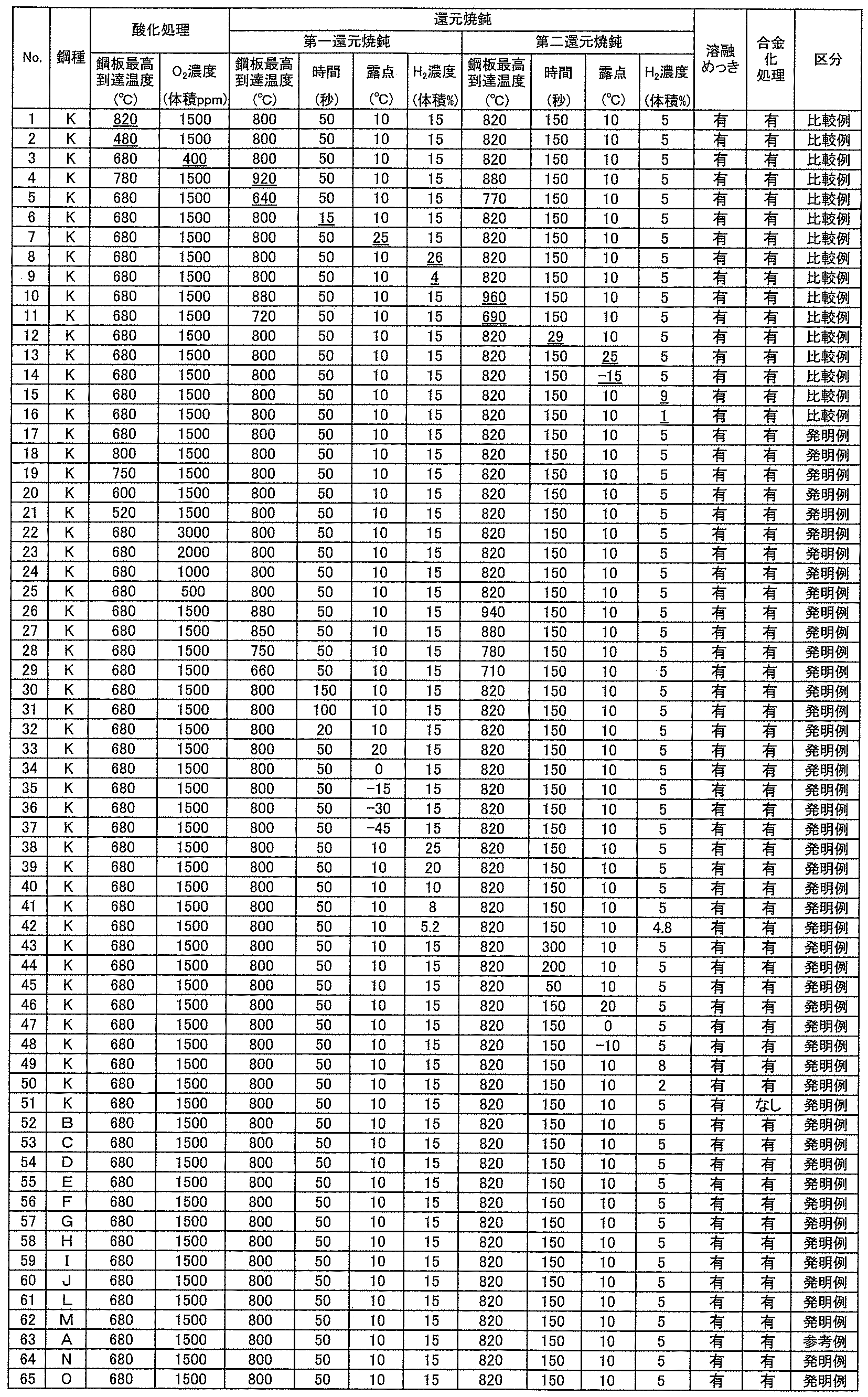
- Example 1 A 1.2 mm cold-rolled sheet having the chemical composition shown in Table 1 was annealed and hot-dip plated in a CGL. Oxidation heating was performed under the conditions shown in Table 2 using a direct-fired heating furnace having a nozzle mix type burner. The oxidation start temperature was set to 300°C. Since the oxidation start temperature does not particularly affect the plating appearance, a temperature below 300°C may be used as the oxidizing atmosphere. Reduction annealing was performed under the conditions shown in Table 2 using a radiant tube type heating furnace separated into two zones by a seal roll, and then cooled.
- This plate assembly was assembled so that the hot-dip galvanized layer of the test piece and the hot-dip galvanized layer surface of the commercially available hot-dip galvanized steel sheet were aligned.
- this plate assembly was fixed to a fixing table via a spacer with a thickness of 2.0 mm in a state of inclination of 5°, which is the maximum inclination expected for some part shapes.
- the spacer was a pair of steel sheets with a length of 50 mm in the longitudinal direction, a transverse direction of 45 mm in the transverse direction, and a thickness of 2.0 mm, and was arranged so that the longitudinal end faces of each of the pair of steel sheets were aligned with both transverse end faces of the plate assembly. Therefore, the distance between the pair of steel plates constituting the spacer is 60 mm.
- the fixing base is a plate with a hole in the center.
- the plate assembly was pressed with a pair of electrodes (tip diameter: 6 mm) while bending the plate assembly, and resistance welding was performed under the conditions of pressure: 3.5 kN, hold time: 0.10 seconds or 0.16 seconds, welding current and welding time conditions that result in a nugget diameter of 5.9 mm at the weld (i.e., the welding current and welding time were appropriately adjusted for each plate assembly so that the nugget diameter was 5.9 mm) to form a plate assembly with a weld.
- the pair of electrodes pressed the plate assembly from above and below in the vertical direction, and the lower electrode pressed the test piece through a hole in the fixing base.
- the lower electrode and the fixing base were fixed so that the lower electrode of the pair of electrodes was in contact with a plane extending from the surface where the spacer and the fixing base were in contact, and the upper electrode was made movable.
- the upper electrode was made to contact the center of the hot-dip galvanized steel sheet for the test.
- the hold time refers to the time from when the welding current stops flowing until the electrodes begin to be released.
- the nugget diameter refers to the distance of the end 10 of the nugget in the longitudinal direction of the plate assembly, as shown in Figure 2.
- the plate assembly with the weld was cut to include the weld (nugget), and the cross section of the weld was observed under an optical microscope (200x) to evaluate the resistance weld crack resistance characteristics of the weld according to the following criteria.
- the upper figure in Figure 2 is a plan view of the plate assembly with the weld, showing the cutting position.
- the lower figure in Figure 2 is a drawing showing the cross section in the plate thickness direction of the plate assembly after cutting, and shows a schematic of cracks that occurred in the test piece. Note that if cracks occur in the test hot-dip galvanized steel sheet, the stress in the test piece will be dispersed and an appropriate evaluation will not be possible. For this reason, data in which no cracks occurred in the test hot-dip galvanized steel sheet was used as the example.
- the resistance crack resistance of the welded part is judged to be good and excellent, respectively, and if it is " ⁇ ", the resistance crack resistance of the welded part is judged to be poor.
- ⁇ No cracks longer than 0.1 mm were observed with a hold time of 0.10 seconds.
- ⁇ A crack having a length of 0.1 mm or more is observed with a hold time of 0.10 seconds, but no crack having a length of 0.1 mm or more is observed with a hold time of 0.16 seconds.
- ⁇ A crack having a length of 0.1 mm or more was observed at a hold time of 0.16 seconds.
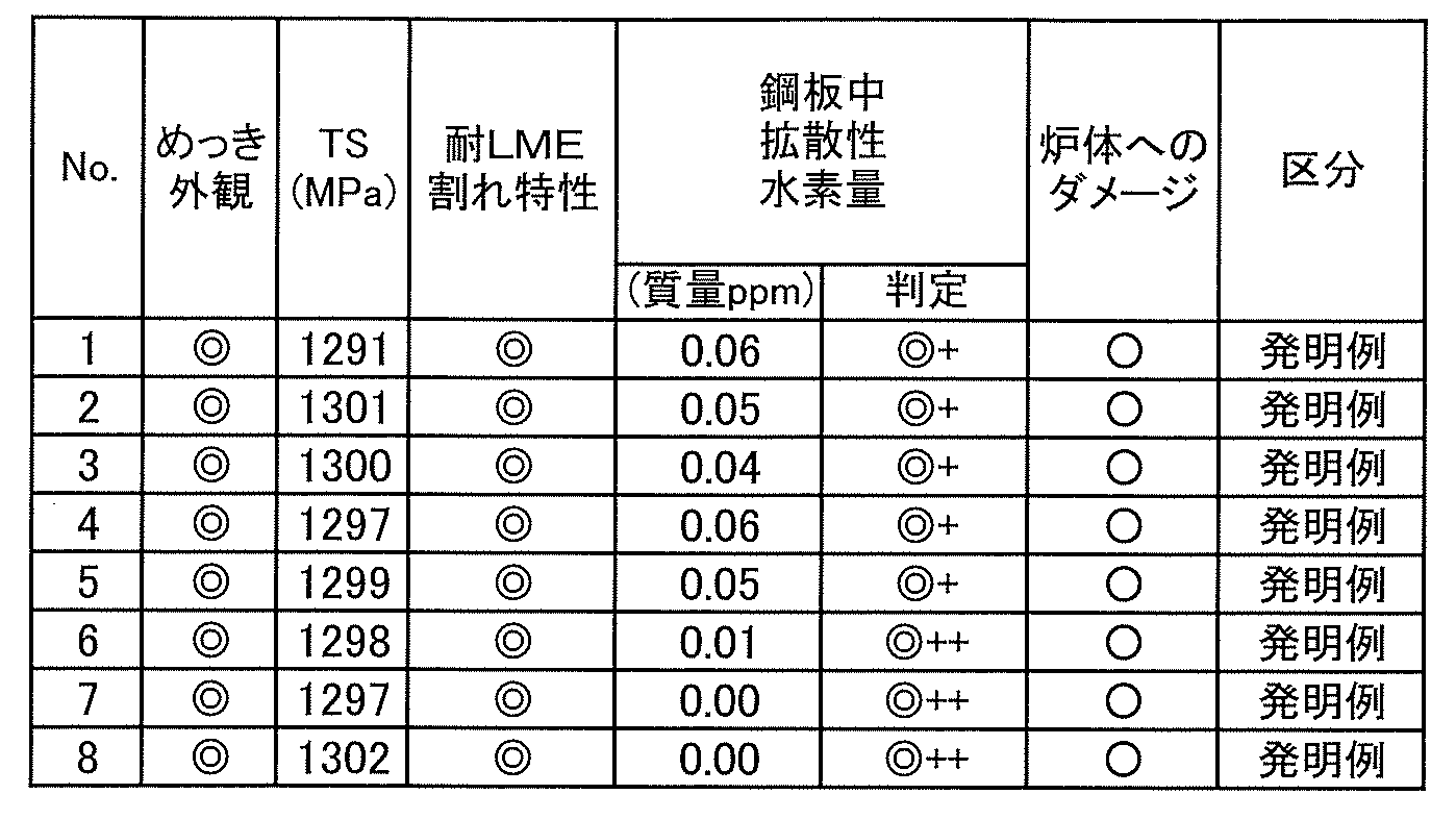
- a steel with a diffusible hydrogen amount of 0.01 mass ppm or less was rated as the highest " ⁇ ++”
- a steel with a diffusible hydrogen amount of 0.06 mass ppm or less was rated as very good " ⁇ +”
- a steel with a diffusible hydrogen amount of 0.10 mass ppm or less was rated as good " ⁇ ”
- a steel with a diffusible hydrogen amount of 0.30 mass ppm or less was rated as pass " ⁇ ”.
- the amount of diffusible hydrogen in steel exceeds 0.30 ppm by mass, the delayed fracture resistance of the steel sheet is often deteriorated, so that an amount of 0.30 ppm by mass or more is marked as ⁇ .
- the dehydrogenation behavior was judged to be excellent when marked with " ⁇ " or " ⁇ ".
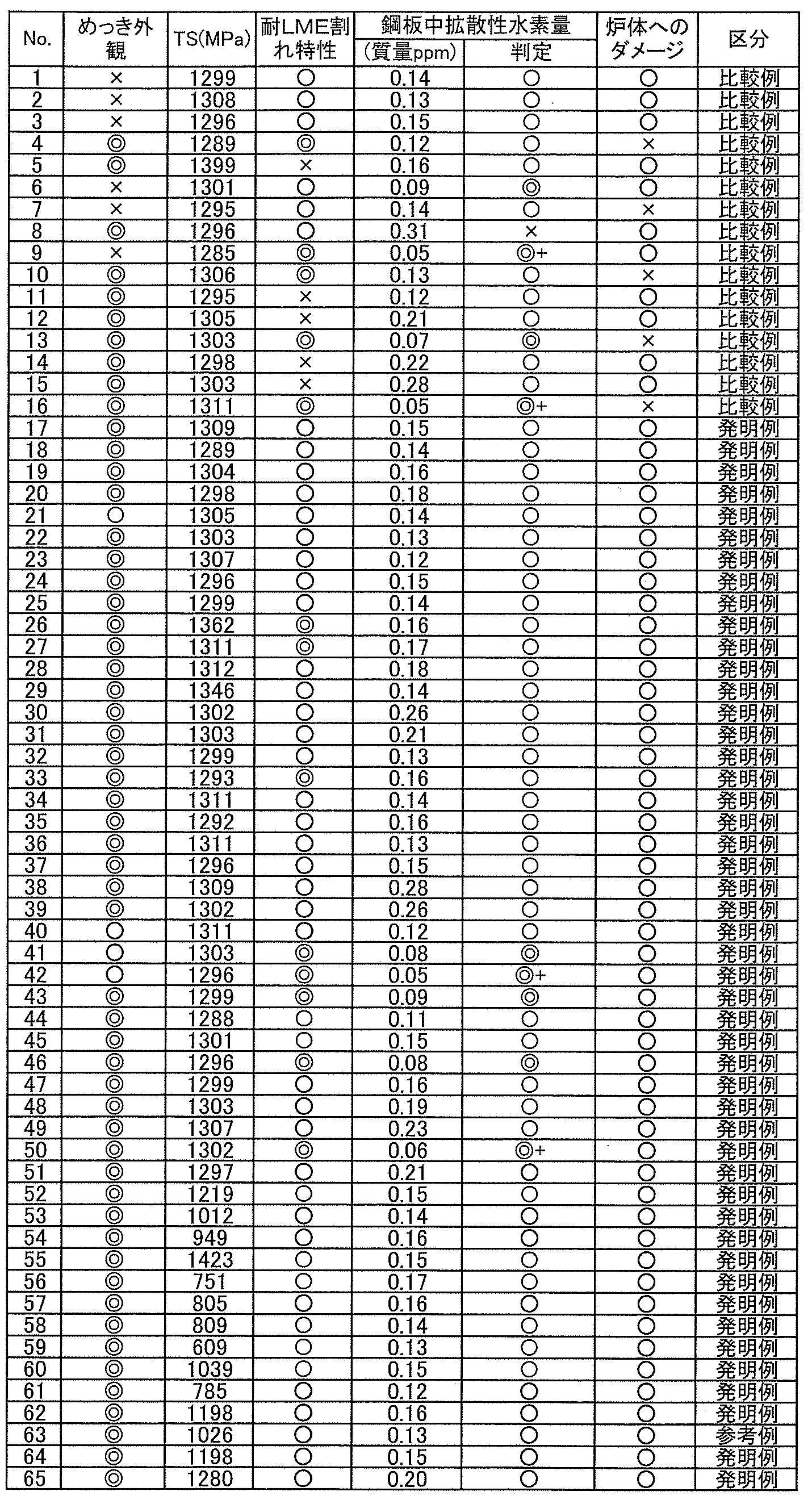
- the examples of the present invention despite being high-strength hot-dip galvanized steel sheets containing Si, have excellent LME cracking resistance, good coating appearance, and low amounts of diffusible hydrogen in the steel sheet, and are expected to have good delayed fracture resistance and cause little damage to the furnace body.
- the comparative examples manufactured outside the scope of the present invention are inferior in one or more of LME cracking resistance, coating appearance, amount of diffusible hydrogen in the steel sheet, and damage to the furnace body.
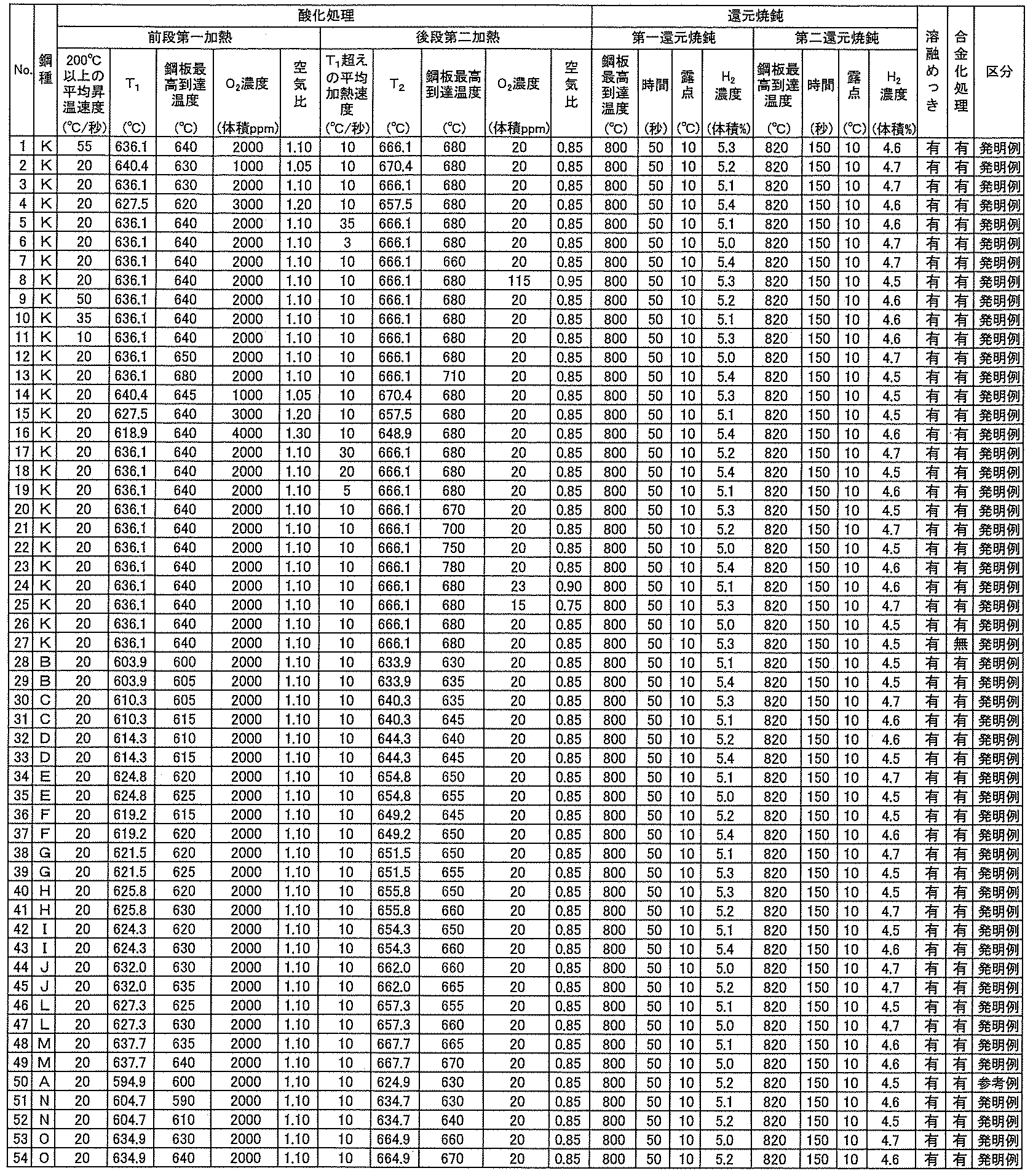
- Example 2 Similarly, a 1.2 mm cold-rolled sheet having the chemical composition shown in Table 1 was annealed and hot-dip galvanized in a CGL. Oxidation heating was performed under the conditions shown in Table 4 in a direct-fired heating furnace having a nozzle mix type burner separated into two zones. Reduction annealing was performed under the conditions shown in Table 4 in a radiant tube type heating furnace separated into two zones by a seal roll, and then cooled. Subsequently, a hot-dip galvanizing process was performed using a 460°C bath containing 0.135% Al, and then the coating weight was adjusted to about 50 g/ m2 by gas wiping. Under some conditions, an alloying process was performed. In Table 4, in the first reduction annealing, the steel sheet was held at the maximum temperature reached for the time shown in the table, and in the second reduction annealing, the steel sheet was held at the maximum temperature reached for the time shown in the table.
- Example 1 the appearance of the high-strength hot-dip galvanized steel sheets obtained as described above was evaluated, and the tensile properties were investigated in the same manner as in Example 1. Furthermore, the LME cracking resistance, dehydrogenation behavior, and damage to the furnace body were evaluated.
- the present invention example is a high-strength hot-dip galvanized steel sheet containing Si, yet it has excellent LME cracking resistance, good coating appearance, and low amount of diffusible hydrogen in the steel sheet, so good delayed fracture resistance can be expected and there is little damage to the furnace body. Furthermore, by using a direct-fired heating furnace with the oxidation heating process separated into two zones, it is possible to achieve a high level of LME cracking resistance, coating appearance, and reduction of diffusible hydrogen in the steel.
- Example 3 Similarly, a 1.2 mm cold-rolled sheet having the chemical composition shown in Table 1 was annealed and hot-dip galvanized in a CGL. Oxidation heating was performed in a direct-fired heating furnace having a nozzle mix type burner separated into two zones under the conditions shown in Table 6. Reduction annealing was performed in a radiant tube type heating furnace separated into two zones by seal rolls under the conditions shown in Table 6, and then cooled. The hydrogen concentrations in both the first reduction annealing and the second reduction annealing in the annealing furnace during reduction annealing were reduced.
- a hot-dip galvanizing treatment was performed using a bath containing 0.135% Al at 460°C, and then the coating weight was adjusted to about 50 g/ m2 by gas wiping. In some conditions, an alloying treatment was performed.
- Table 6 in the first reduction annealing, the steel sheet was held at the maximum temperature reached for the time shown in the table, and in the second reduction annealing, the steel sheet was held at the maximum temperature reached for the time shown in the table.
- Example 1 the appearance of the high-strength hot-dip galvanized steel sheets obtained as described above was evaluated, and the tensile properties were investigated in the same manner as in Example 1. Furthermore, the LME cracking resistance, dehydrogenation behavior, and damage to the furnace body were evaluated.
- the present invention example despite being a high-strength hot-dip galvanized steel sheet containing Si, has excellent LME cracking resistance, a good coating appearance, and a small amount of diffusible hydrogen in the steel sheet, so good delayed fracture resistance can be expected and there is little damage to the furnace body. Furthermore, by lowering the hydrogen concentration in the annealing furnace, it is possible to reduce diffusible hydrogen in the steel to the utmost.
- the high-strength hot-dip galvanized steel sheet obtained by the manufacturing method of the present invention has excellent appearance quality and resistance weld cracking properties, and at the same time, it is possible to suppress the deterioration of delayed fracture resistance properties caused by hydrogen embrittlement, and it can be used as a surface-treated steel sheet to reduce the weight and increase the strength of the automobile body itself.
- Reference Signs List 1 Test hot-dip galvanized steel sheet 2: Test piece 3: Spacer 4: Electrode 5: Fixing stand 6: Nugget 7: Nugget diameter 8: Cutting line
Landscapes
- Chemical & Material Sciences (AREA)
- Engineering & Computer Science (AREA)
- Materials Engineering (AREA)
- Mechanical Engineering (AREA)
- Metallurgy (AREA)
- Organic Chemistry (AREA)
- Thermal Sciences (AREA)
- Physics & Mathematics (AREA)
- Chemical Kinetics & Catalysis (AREA)
- Crystallography & Structural Chemistry (AREA)
- Oil, Petroleum & Natural Gas (AREA)
- Heat Treatment Of Sheet Steel (AREA)
- Coating With Molten Metal (AREA)
Abstract
Description
前記酸化処理では、N2と500体積ppm以上のO2を含む雰囲気中で、鋼板を500℃以上800℃以下の範囲に設ける酸化工程で酸化させ、
前記還元焼鈍を前段と後段の異なる雰囲気中で行い、前段の第一還元焼鈍では、鋼板を焼鈍雰囲気の露点-45℃以上+20℃以下で、水素を5.0体積%以上25体積%以下、残部N2を含む雰囲気中で650℃以上900℃以下の温度に20秒以上150秒以下保持し、
後段の第二還元焼鈍では、前記第一還元焼鈍後の鋼板を、焼鈍雰囲気の露点-10℃以上+20℃以下で、水素を2.0体積%以上8.0体積%以下、残部N2を含み、かつ、前段の第一還元焼鈍における水素濃度をH2a、後段の第二還元焼鈍における水素濃度をH2bとした時に、H2a>H2bとなるように水素濃度を調整した雰囲気中で、700℃以上950℃以下の温度に30秒以上300秒以下保持した後に溶融亜鉛めっきを行う高強度溶融亜鉛めっき鋼板の製造方法。
[2]前記還元焼鈍は、鋼板走行方向に2以上に分割された、2以上の異なる雰囲気で焼鈍が可能である焼鈍炉を用いる[1]に記載の高強度溶融亜鉛めっき鋼板の製造方法。
[3]鋼板に、溶融亜鉛めっきを施した後、溶融亜鉛めっきの合金化処理を行う[1]または[2]に記載の高強度溶融亜鉛めっき鋼板の製造方法。
[4]前記酸化処理を、還元焼鈍の前工程として実施する鋼板の昇温工程で行う[1]~[3]のいずれかに記載の高強度溶融亜鉛めっき鋼板の製造方法。
[5]前記酸化処理を、500℃以上800℃以下の少なくとも50℃以上の温度範囲で行う[4]に記載の高強度溶融亜鉛めっき鋼板の製造方法。
[6]前記酸化処理を、直火型加熱炉(DFF)を用い、少なくとも加熱炉内雰囲気の一部の空気比を1.0以上とすることで、鋼板表面を酸化させる[1]~[5]のいずれかに記載の高強度溶融亜鉛めっき鋼板の製造方法。
[7]前記酸化処理は、鋼板走行方向に2以上に分割され、2以上の雰囲気で酸化が可能である直火型加熱炉を用い、
加熱炉前段の第一加熱帯では、前記酸化処理を行う温度域の空気比をαとしたとき、200℃以上での平均昇温速度が10℃/秒以上50℃/秒以下の条件で、下記式(1)から算出されるT1(℃)以上の温度に加熱し、
加熱炉後段の第二加熱帯では、第一加熱帯を経た鋼板を、空気比≦0.9、T1(℃)超えの平均加熱速度が5℃/秒以上30℃/秒以下の条件で、下記式(2)から算出されるT2(℃)以上の温度に加熱する[1]~[6]のいずれかに記載の高強度溶融亜鉛めっき鋼板の製造方法。
T1=28.2[Si]+7.95[Mn]-86.2α+666 ‐‐‐(1)
T2=T1+30 ‐‐‐(2)
ここで、[Si]は鋼板に含まれるSi含有量(質量%)であり、[Mn]は鋼板に含まれるMn含有量(質量%)である。
[8]前記酸化処理を、N2と500体積ppm以上のO2を含み、その他にCO、CO2、H2O、NOXの一種または二種以上を含む雰囲気にて行う[1]~[7]のいずれかに記載の高強度溶融亜鉛めっき鋼板の製造方法。
[9]前記酸化処理を、ラジアントチューブ型加熱炉を用いて行う[1]~[5]、[8]のいずれかに記載の高強度溶融亜鉛めっき鋼板の製造方法。
[10]前記還元焼鈍を、ラジアントチューブ型加熱・均熱炉を用いて行う[1]~[5]、[8]、[9]のいずれかに記載の高強度溶融亜鉛めっき鋼板の製造方法。
[11]前記第二還元焼鈍で、焼鈍雰囲気の水素が2.0体積%以上5.0体積%未満、残部N2を含む[1]~[10]のいずれかに記載の高強度溶融亜鉛めっき鋼板の製造方法。
[12]前記第一還元焼鈍では、焼鈍雰囲気の水素が5.0体積%以上12体積%以下、残部N2を含み、前記第二還元焼鈍で、焼鈍雰囲気の水素が2.0体積%以上3.0体積%未満、残部N2を含む[1]~[11]のいずれかに記載の高強度溶融亜鉛めっき鋼板の製造方法。
Siは、加工性を大きく損なうことなく、固溶により鋼の強度を高める効果(固溶強化能)が大きいため、鋼板の高強度化を達成するのに有効な元素である。一方で、Siは溶接部における耐抵抗溶接割れ特性に悪影響を及ぼす元素でもある。Siを鋼板の高強度化を達成するために添加する場合には、0.45%以上の含有が必要である。また、Si含有量が0.45%未満では、溶接部における耐抵抗溶接割れ特性に特に問題は生じず、本発明を適用する必要性に乏しい。一方、Si含有量が2.0%を超えると、熱間圧延性および冷間圧延性が大きく低下し、生産性に悪影響を及ぼしたり、鋼板自体の延性の低下を招いたりする。よって、Siは0.45%以上2.0%以下の範囲で含有する。Si含有量は、好ましくは0.7%以上、より好ましくは0.9%以上とする。また、Si含有量は、好ましくは1.8%以下、より好ましくは1.6%以下とする。
Cは、鋼組織としてマルテンサイトなどを形成させることで鋼板の加工性が向上する。Cを含有させる場合、良好な溶接性を得るため、C含有量は0.3%以下とすることが好ましく、0.25%以下とすることがより好ましい。Cの下限は特に限定されないが、良好な加工性を得るためにはCを0.03%以上とすることが好ましく、0.05%以上含有させることがより好ましい。
Mnは、鋼を固溶強化して高強度化するとともに、焼入性を高め、残留オーステナイト、ベイナイト、およびマルテンサイトの生成を促進する作用を有する元素である。このような効果は、Mnを1.0%以上含有することで発現する。一方、Mn含有量が4.0%以下であれば、コストの上昇を招かずに上記効果が得られる。よって、Mn含有量は1.0%以上とすることが好ましく、4.0%以下とすることが好ましい。Mn含有量は1.8%以上とすることがより好ましい。また、Mn含有量は3.3%以下とすることがより好ましい。
Pの含有量を抑制することで、溶接性の低下を防ぐことができる。さらにPが粒界に偏析することを防いで、延性、曲げ性、および靭性が劣化することを防ぐことができる。また、Pを多量に添加すると、フェライト変態を促進することで結晶粒径も大きくなってしまう。そのため、P含有量は0.1%以下とすることが好ましい。Pの下限は特に限定されず、生産技術上の制約から0%超であり、通常0.001%以上である。
S含有量は0.03%以下とすることが好ましく、0.02%以下とすることがより好ましい。S含有量を抑制することで、溶接性の低下を防ぐとともに、熱間圧延時の延性の低下を防いで、熱間割れを抑制し、表面性状を著しく向上させることができる。さらに、S含有量を抑制することで、不純物元素として粗大な硫化物を形成することにより、鋼板の延性、曲げ性、伸びフランジ性の低下を防ぐことができる。これらの問題はS含有量が0.03%を超えると顕著となり、Sの含有量は極力低減することが好ましい。Sの下限は特に限定されず、生産技術上の制約から0%超であり、通常0.0001%以上である。
Nの含有量は0.010%以下とすることが好ましい。Nの含有量を0.010%以下とすることで、NがTi、Nb、Vと高温で粗大な窒化物を形成し、これにより、Ti、Nb、V添加による鋼板の高強度化の効果が損なわれることを防ぐことができる。また、Nの含有量を0.010%以下とすることで靭性の低下も防ぐことができる。さらに、Nの含有量を0.010%以下とすることで、熱間圧延中にスラブ割れ、表面疵が発生することを防ぐことができる。Nの含有量は、好ましくは0.005%以下であり、より好ましくは0.003%以下であり、さらに好ましくは0.002%以下である。Nの含有量の下限は特に限定されず、生産技術上の制約から0%超であり、通常0.0005%以上である。
Alは熱力学的に最も酸化しやすいため、SiおよびMnに先だって酸化し、SiおよびMnの鋼板最表層での酸化を抑制し、SiおよびMnの鋼板内部での酸化を促進する効果がある。この効果はAl含有量が0.01%以上で得られる。一方、Al含有量が0.1%を超えるとコストアップになる。したがって、添加する場合、Al含有量は0.1%以下とすることが好ましい。Alの下限は特に限定されず、0%超であり、通常0.001%以上である。
Bは鋼の焼入れ性を向上させるのに有効な元素である。焼入れ性を向上するためには、B含有量は0.0003%以上とすることが好ましく、0.0005%以上とすることがより好ましい。しかし、Bを過度に添加すると成形性が低下するため、B含有量は0.005%以下とすることが好ましい。
Tiは鋼の析出強化に有効である。Tiの下限は特に限定されないが、強度調整の効果を得るためには、0.005%以上とすることが好ましい。しかし、Tiを過度に添加すると、硬質相が過大となり、成形性が低下するため、Tiを添加する場合、Ti含有量は0.2%以下とすることが好ましく、0.05%以下とすることがより好ましい。
Cr含有量は0.005%以上とすることが好ましい。Cr含有量を0.005%以上とすることで、焼き入れ性が向上し、強度と延性とのバランスを向上させることができる。Crを添加する場合、コストアップを防ぐ観点から、Cr含有量は1.0%以下とすることが好ましい。
Mo含有量は0.005%以上とすることが好ましい。Mo含有量を0.005%以上とすることで、強度調整の効果を得ることができる。Mo含有量はより好ましくは0.05%以上とする。また、Moを添加する場合、コストアップを防ぐ観点から、Mo含有量は1.0%以下が好ましい。
Cu含有量は0.005%以上とすることが好ましい。Cu含有量を0.005%以上とすることで、残留γ相の形成を促進することができる。また、Cuを添加する場合、コストアップを防ぐ観点から、Cu含有量は1.0%以下とすることが好ましい。
Ni含有量は0.005%以上とすることが好ましい。Ni含有量を0.005%以上とすることで、残留γ相の形成を促進することができる。また、Niを添加する場合、コストアップを防ぐ観点から、Ni含有量は1.0%以下とすることが好ましい。
Nbは、0.005%以上含有することで強度向上の効果が得られる。また、Nbを含有する場合、コストアップを防ぐ観点から、Nb含有量は0.20%以下とすることが好ましい。
Sbは鋼板表面の窒化、酸化、あるいは酸化により生じる、鋼板表面から数十ミクロンの深さまでの領域の脱炭を抑制する観点から含有することができる。Sbは、鋼板表面の窒化および酸化を抑制することで、鋼板表面においてマルテンサイトの生成量が減少するのを防止し、鋼板の疲労特性および表面品質を改善する。このような効果を得るために、Sb含有量は0.001%以上とすることが好ましい。一方、良好な靭性を得るためには、Sb含有量は0.200%以下とすることが好ましい。
Vは、0.005%以上含有することで強度向上の効果が得られる。また、Vを含有する場合、コストアップを防ぐ観点から、Vを含有する場合、V含有量は0.5%以下とすることが好ましい。
Taは、0.001%以上含有することで強度向上の効果が得られる。また、Taを含有する場合、コストアップを防ぐ観点から、Taを含有する場合、Ta含有量は0.1%以下とすることが好ましい。
Wは、0.005%以上含有することで強度向上の効果が得られる。また、Wを含有する場合、コストアップを防ぐ観点から、Wを含有する場合、W含有量は0.5%以下とすることが好ましい。
Zrは、0.0005%以上含有することで強度向上の効果が得られる。また、Zrを含有する場合、コストアップを防ぐ観点から、Zrを含有する場合、Zr含有量は0.1%以下とすることが好ましい。
Snは脱窒、脱硼等を抑制して、鋼の強度低下抑制に有効な元素である。こうした効果を得るには0.002%以上含有することが好ましい。一方、良好な耐衝撃性を得るために、Sn含有量は0.20%以下とすることが好ましい。
Caは、0.0005%以上含有することで硫化物の形態を制御し、延性、靭性を向上させることができる。また、良好な延性を得る観点から、Caを含有する場合、Ca含有量は0.005%以下とすることが好ましい。
Mgは、0.0005%以上含有することで硫化物の形態を制御し、延性、靭性を向上させることができる。また、Mgを含有する場合、コストアップを防ぐ観点から、Mgを含有する場合、Mg含有量は0.005%以下とすることが好ましい。
REMは、0.0005%以上含有することで硫化物の形態を制御し、延性、靭性を向上させることができる。また、REMを含有する場合、良好な靭性を得る観点から、REM含有量は0.005%以下とすることが好ましい。
T1=28.2[Si]+7.95[Mn]-86.2α+666 ‐‐‐(1)
ただし、[Si]:鋼中のSi質量%、[Mn]:鋼中のMn質量%、α:直火型加熱炉の空気比である。
ここでの平均昇温速度(℃/秒)は、昇温終了温度(鋼板最高到達温度(T1以上))(℃)と昇温開始温度(200℃以上)との差を昇温時間(s)で割ることにより得られる。
T2=T1+30 ‐‐‐(2)
表1に示す化学成分の1.2mmの冷間圧延板を、CGLで焼鈍および溶融めっき処理を行った。酸化加熱はノズルミックス型バーナーを有する直火型加熱炉により表2に示す条件にて行った。なお、酸化開始温度は300℃とした。酸化開始温度は特にめっき外観に影響がないため、300℃未満を酸化雰囲気としても良い。還元焼鈍はシールロールで2つの区域に分離されたラジアントチューブ型の加熱炉で表2に示す条件にて行い冷却した。引き続き、0.135質量%のAlを含有した460℃の亜鉛めっき浴を用いて溶融亜鉛めっき処理を施した後に、ガスワイピングで目付け量を片面当たり約50g/m2に調整した。一部の条件では、合金化処理を行った。表2中、第一還元焼鈍では、鋼板最高到達温度で表中に示す時間保持を行い、第二還元焼鈍では、鋼板最高到達温度で表中に示す時間保持を行った。

鋼板の外観を目視観察し、不めっき、ピックアップ現象による押し疵、または合金化ムラなどの外観不良がないものを「◎」、外観不良がわずかにあるが製品として許容範囲であるものを「〇」、明瞭な合金化ムラ、不めっき、または押し疵があるものは「×」とした。上記評価が「〇」、「◎」であれば、外観良好と判定した。
圧延方向を引張方向としてJIS5号試験片を用いてJIS Z2241に準拠した方法で行った。
溶融亜鉛めっき鋼板から圧延直角方向(TD)を長手、圧延方向を短手として、長手方向150mm×短手方向50mmに切り出した試験片を、同サイズに切り出した、溶融亜鉛めっき層の片面あたりのめっき付着量が50g/m2である試験用溶融亜鉛めっき鋼板(板厚1.2mm、TS:980MPa級)と重ねて板組とした。この板組は、試験片の溶融亜鉛めっき層と、市販の溶融亜鉛めっき鋼板の溶融亜鉛めっき層面とを合わせるように組み立てた。図1に示すように、この板組を、厚さ2.0mmのスペーサーを介して、一部の部品形状で想定される最大の傾きである5°傾けた状態で固定台に固定した。スペーサーは、長手方向50mm×短手方向45mm×厚さ2.0mmの一対の鋼板であり、この一対の鋼板各々の長手方向端面が、板組の短手方向両端面とそろうように配置した。したがって、スペーサーを構成する一対の鋼板間の距離は60mmとなる。固定台は、中央部に穴が開いた一枚の板である。
○:ホールドタイム0.10秒で0.1mm以上の長さのき裂が認められるが、ホールドタイム0.16秒で0.1mm以上の長さのき裂が認められない。
×:ホールドタイム0.16秒で0.1mm以上の長さのき裂が認められる。
溶融亜鉛めっき鋼板の幅中央部から、長軸長さ30mm、短軸長さ5mmの短冊状の試験片を採取し、その試験片のめっき層をリューターで除去し、直ちに、昇温脱離分析装置を用いて分析開始温度25℃、分析終了温度300℃、昇温速度200℃/時間の条件で水素分析し、各温度において試験片表面から放出される水素量である放出水素量(質量ppm/min)を測定した。分析開始温度から300℃までの放出水素量の合計を鋼中拡散性水素量として算出した。ここで、鋼中拡散性水素量が0.01質量ppm以下のものを最高「◎++」とし、0.06質量ppm以下のものを極めて良好「◎+」とし、0.10質量ppm以下のものを良好「◎」とし、0.30質量ppm以下を合格「〇」とした。また、経験上、鋼中拡散性水素量が0.30質量ppmを超えると、鋼板の耐遅れ破壊特性が低下することが多いことから、0.30質量ppm以上は×とした。脱水素挙動は「◎」と「〇」の場合が優れると判定した。
炉体へのダメージは、焼鈍炉内の鉄皮(SUS310S)に変色が認められたかどうか、目視によって評価した。ここで、鉄皮に変色が認められなかったものを「〇」とし、炉体ダメージを与えないと判定した。明らかに変色が認められたものを「×」とし炉体ダメージを与えると判定した。
以上により得られた結果を製造条件と併せて表3に示す。
同様に表1に示す化学成分の1.2mmの冷間圧延板を、CGLで焼鈍および溶融めっき処理を行った。酸化加熱は2つの区域に分離されたノズルミックス型バーナーを有する直火型加熱炉により表4に示す条件にて行った。還元焼鈍はシールロールで2つの区域に分離されたラジアントチューブ型の加熱炉で表4に示す条件にて行い冷却した。引き続き、0.135%のAlを含有した460℃の浴を用いて溶融亜鉛めっき処理を施した後にガスワイピングで目付け量を約50g/m2に調整した。一部の条件では、合金化処理を行った。表4中、第一還元焼鈍では、鋼板最高到達温度で表中に示す時間保持を行い、第二還元焼鈍では、鋼板最高到達温度で表中に示す時間保持を行った。
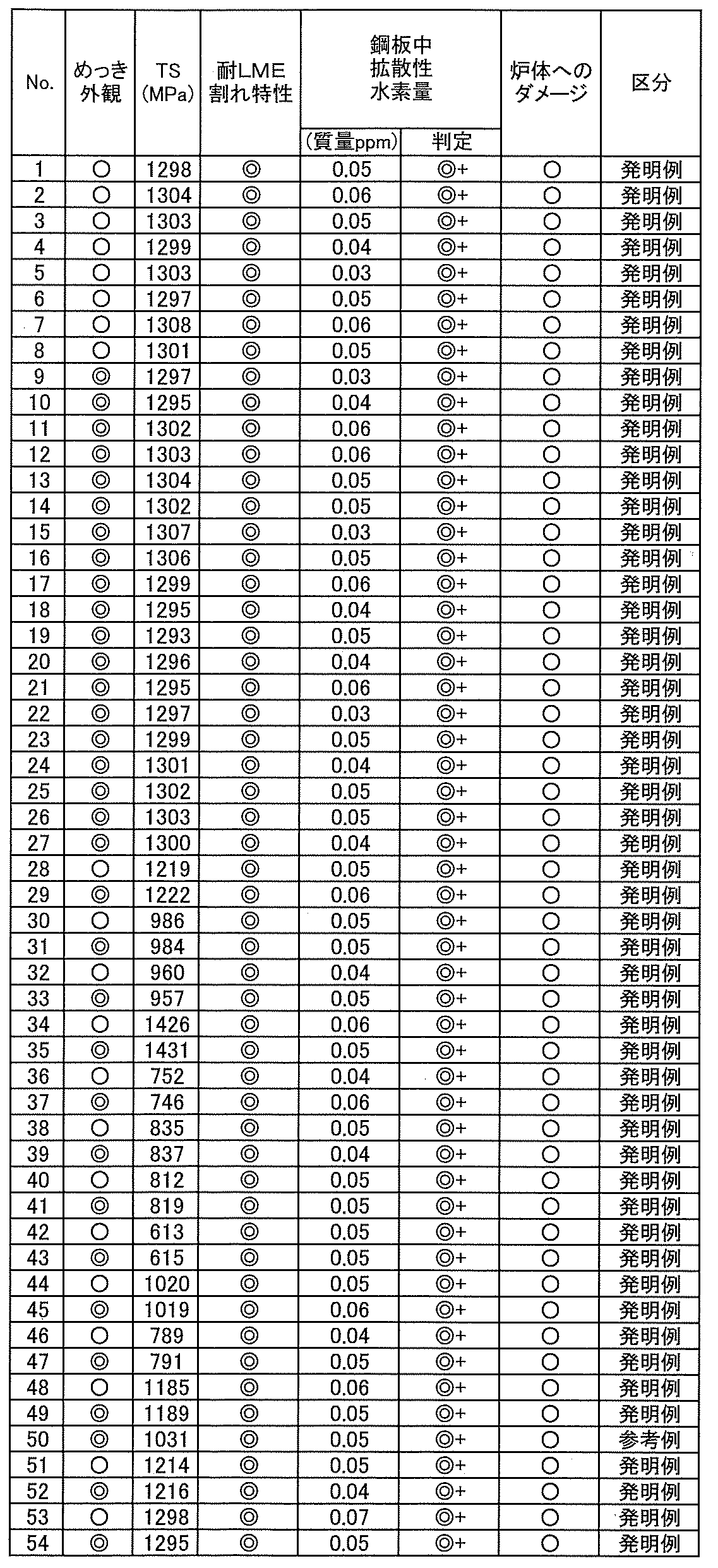
同様に表1に示す化学成分の1.2mmの冷間圧延板を、CGLで焼鈍および溶融めっき処理を行った。酸化加熱は2つの区域に分離されたノズルミックス型バーナーを有する直火型加熱炉により表6に示す条件にて行った。還元焼鈍はシールロールで2つの区域に分離されたラジアントチューブ型の加熱炉で表6に示す条件にて行い冷却した。還元焼鈍における焼鈍炉内の第一還元焼鈍、第二還元焼鈍の水素濃度は、ともに低濃度化した。
引き続き、0.135%のAlを含有した460℃の浴を用いて溶融亜鉛めっき処理を施した後にガスワイピングで目付け量を約50g/m2に調整した。一部の条件では、合金化処理を行った。表6中、第一還元焼鈍では、鋼板最高到達温度で表中に示す時間保持を行い、第二還元焼鈍では、鋼板最高到達温度で表中に示す時間保持を行った。

2 試験片
3 スペーサー
4 電極
5 固定台
6 ナゲット
7 ナゲット径
8 切断線
Claims (12)
- 質量%で、Si:0.45%以上2.0%以下を含有する鋼板を酸化処理し、次いで還元焼鈍した後、溶融亜鉛めっきを行う高強度溶融亜鉛めっき鋼板の製造方法であって、
前記酸化処理では、N2と500体積ppm以上のO2を含む雰囲気中で、鋼板を500℃以上800℃以下の範囲に設ける酸化工程で酸化させ、
前記還元焼鈍を前段と後段の異なる雰囲気中で行い、前段の第一還元焼鈍では、鋼板を焼鈍雰囲気の露点-45℃以上+20℃以下で、水素を5.0体積%以上25体積%以下、残部N2を含む雰囲気中で650℃以上900℃以下の温度に20秒以上150秒以下保持し、
後段の第二還元焼鈍では、前記第一還元焼鈍後の鋼板を、焼鈍雰囲気の露点-10℃以上+20℃以下で、水素を2.0体積%以上8.0体積%以下、残部N2を含み、かつ、前段の第一還元焼鈍における水素濃度をH2a、後段の第二還元焼鈍における水素濃度をH2bとした時に、H2a>H2bとなるように水素濃度を調整した雰囲気中で、700℃以上950℃以下の温度に30秒以上300秒以下保持した後に溶融亜鉛めっきを行う高強度溶融亜鉛めっき鋼板の製造方法。 - 前記還元焼鈍は、鋼板走行方向に2以上に分割された、2以上の異なる雰囲気で焼鈍が可能である焼鈍炉を用いる請求項1に記載の高強度溶融亜鉛めっき鋼板の製造方法。
- 鋼板に、溶融亜鉛めっきを施した後、溶融亜鉛めっきの合金化処理を行う請求項1または2に記載の高強度溶融亜鉛めっき鋼板の製造方法。
- 前記酸化処理を、還元焼鈍の前工程として実施する鋼板の昇温工程で行う請求項1~3のいずれかに記載の高強度溶融亜鉛めっき鋼板の製造方法。
- 前記酸化処理を、500℃以上800℃以下の少なくとも50℃以上の温度範囲で行う請求項4に記載の高強度溶融亜鉛めっき鋼板の製造方法。
- 前記酸化処理を、直火型加熱炉(DFF)を用い、少なくとも加熱炉内雰囲気の一部の空気比を1.0以上とすることで、鋼板表面を酸化させる請求項1~5のいずれかに記載の高強度溶融亜鉛めっき鋼板の製造方法。
- 前記酸化処理は、鋼板走行方向に2以上に分割され、2以上の雰囲気で酸化が可能である直火型加熱炉を用い、
加熱炉前段の第一加熱帯では、前記酸化処理を行う温度域の空気比をαとしたとき、200℃以上での平均昇温速度が10℃/秒以上50℃/秒以下の条件で、下記式(1)から算出されるT1(℃)以上の温度に加熱し、
加熱炉後段の第二加熱帯では、第一加熱帯を経た鋼板を、空気比≦0.9、T1(℃)超えの平均加熱速度が5℃/秒以上30℃/秒以下の条件で、下記式(2)から算出されるT2(℃)以上の温度に加熱する請求項1~6のいずれかに記載の高強度溶融亜鉛めっき鋼板の製造方法。
T1=28.2[Si]+7.95[Mn]-86.2α+666 ‐‐‐(1)
T2=T1+30 ‐‐‐(2)
ここで、[Si]は鋼板に含まれるSi含有量(質量%)であり、[Mn]は鋼板に含まれるMn含有量(質量%)である。 - 前記酸化処理を、N2と500体積ppm以上のO2を含み、その他にCO、CO2、H2O、NOXの一種または二種以上を含む雰囲気にて行う請求項1~7のいずれかに記載の高強度溶融亜鉛めっき鋼板の製造方法。
- 前記酸化処理を、ラジアントチューブ型加熱炉を用いて行う請求項1~5、8のいずれかに記載の高強度溶融亜鉛めっき鋼板の製造方法。
- 前記還元焼鈍を、ラジアントチューブ型加熱・均熱炉を用いて行う請求項1~5、8、9のいずれかに記載の高強度溶融亜鉛めっき鋼板の製造方法。
- 前記第二還元焼鈍で、焼鈍雰囲気の水素が2.0体積%以上5.0体積%未満、残部N2を含む請求項1~10のいずれかに記載の高強度溶融亜鉛めっき鋼板の製造方法。
- 前記第一還元焼鈍では、焼鈍雰囲気の水素が5.0体積%以上12体積%以下、残部N2を含み、前記第二還元焼鈍で、焼鈍雰囲気の水素が2.0体積%以上3.0体積%未満、残部N2を含む請求項1~11のいずれかに記載の高強度溶融亜鉛めっき鋼板の製造方法。
Priority Applications (5)
| Application Number | Priority Date | Filing Date | Title |
|---|---|---|---|
| PCT/JP2023/016785 WO2024224582A1 (ja) | 2023-04-28 | 2023-04-28 | 高強度溶融亜鉛めっき鋼板の製造方法 |
| EP23935360.0A EP4663783A4 (en) | 2023-04-28 | 2023-04-28 | PROCESS FOR PRODUCING HIGH-STRENGTH HOT-DIMMING GALVANIZED STEEL SHEET |
| CN202380097232.0A CN120958149A (zh) | 2023-04-28 | 2023-04-28 | 高强度热镀锌钢板的制造方法 |
| KR1020257034641A KR20250168369A (ko) | 2023-04-28 | 2023-04-28 | 고강도 용융 아연 도금 강판의 제조 방법 |
| MX2025012703A MX2025012703A (es) | 2023-04-28 | 2025-10-23 | Metodo para la fabricacion de lamina de acero galvanizada por inmersion en caliente de alta resistencia |
Applications Claiming Priority (1)
| Application Number | Priority Date | Filing Date | Title |
|---|---|---|---|
| PCT/JP2023/016785 WO2024224582A1 (ja) | 2023-04-28 | 2023-04-28 | 高強度溶融亜鉛めっき鋼板の製造方法 |
Publications (1)
| Publication Number | Publication Date |
|---|---|
| WO2024224582A1 true WO2024224582A1 (ja) | 2024-10-31 |
Family
ID=93255765
Family Applications (1)
| Application Number | Title | Priority Date | Filing Date |
|---|---|---|---|
| PCT/JP2023/016785 Ceased WO2024224582A1 (ja) | 2023-04-28 | 2023-04-28 | 高強度溶融亜鉛めっき鋼板の製造方法 |
Country Status (5)
| Country | Link |
|---|---|
| EP (1) | EP4663783A4 (ja) |
| KR (1) | KR20250168369A (ja) |
| CN (1) | CN120958149A (ja) |
| MX (1) | MX2025012703A (ja) |
| WO (1) | WO2024224582A1 (ja) |
Cited By (2)
| Publication number | Priority date | Publication date | Assignee | Title |
|---|---|---|---|---|
| JP7841671B1 (ja) * | 2024-11-12 | 2026-04-07 | Jfeスチール株式会社 | 低固溶Si濃度層の厚さの分析方法および鋼材の耐LME性の評価方法 |
| WO2026105490A1 (ja) * | 2024-11-12 | 2026-05-21 | Jfeスチール株式会社 | 低固溶Si濃度層の厚さの分析方法および鋼材の耐LME性の評価方法 |
Citations (6)
| Publication number | Priority date | Publication date | Assignee | Title |
|---|---|---|---|---|
| JP2012149307A (ja) * | 2011-01-20 | 2012-08-09 | Jfe Steel Corp | めっき密着性および摺動特性に優れた合金化溶融亜鉛めっき鋼板の製造方法 |
| WO2014073520A1 (ja) * | 2012-11-06 | 2014-05-15 | 新日鐵住金株式会社 | 合金化溶融亜鉛めっき鋼板とその製造方法 |
| JP2014525986A (ja) * | 2011-07-11 | 2014-10-02 | ティッセンクルップ スチール ヨーロッパ アクチェンゲゼルシャフト | 溶融めっきによる金属保護層を備えた鋼板製品の製造方法 |
| JP6052270B2 (ja) | 2013-12-13 | 2016-12-27 | Jfeスチール株式会社 | 高強度溶融亜鉛めっき鋼板およびその製造方法 |
| JP6172297B2 (ja) | 2014-09-08 | 2017-08-02 | Jfeスチール株式会社 | 高強度溶融亜鉛めっき鋼板の製造方法及び製造設備 |
| WO2021166350A1 (ja) * | 2020-02-21 | 2021-08-26 | Jfeスチール株式会社 | 高強度溶融亜鉛めっき鋼板の製造方法 |
Family Cites Families (3)
| Publication number | Priority date | Publication date | Assignee | Title |
|---|---|---|---|---|
| JP5793971B2 (ja) * | 2011-06-01 | 2015-10-14 | Jfeスチール株式会社 | 材質安定性、加工性およびめっき外観に優れた高強度溶融亜鉛めっき鋼板の製造方法 |
| JP6237937B2 (ja) * | 2016-03-11 | 2017-11-29 | Jfeスチール株式会社 | 高強度溶融亜鉛めっき鋼板の製造方法 |
| US20240229211A9 (en) * | 2021-03-08 | 2024-07-11 | Kabushiki Kaisha Kobe Seiko Sho (Kobe Steel, Ltd.) | Method for manufacturing hot-dip galvanized steel sheet and method for manufacturing alloyed hot-dip galvanized steel sheet |
-
2023
- 2023-04-28 KR KR1020257034641A patent/KR20250168369A/ko active Pending
- 2023-04-28 EP EP23935360.0A patent/EP4663783A4/en active Pending
- 2023-04-28 WO PCT/JP2023/016785 patent/WO2024224582A1/ja not_active Ceased
- 2023-04-28 CN CN202380097232.0A patent/CN120958149A/zh active Pending
-
2025
- 2025-10-23 MX MX2025012703A patent/MX2025012703A/es unknown
Patent Citations (7)
| Publication number | Priority date | Publication date | Assignee | Title |
|---|---|---|---|---|
| JP2012149307A (ja) * | 2011-01-20 | 2012-08-09 | Jfe Steel Corp | めっき密着性および摺動特性に優れた合金化溶融亜鉛めっき鋼板の製造方法 |
| JP5652219B2 (ja) | 2011-01-20 | 2015-01-14 | Jfeスチール株式会社 | めっき密着性および摺動特性に優れた合金化溶融亜鉛めっき鋼板の製造方法 |
| JP2014525986A (ja) * | 2011-07-11 | 2014-10-02 | ティッセンクルップ スチール ヨーロッパ アクチェンゲゼルシャフト | 溶融めっきによる金属保護層を備えた鋼板製品の製造方法 |
| WO2014073520A1 (ja) * | 2012-11-06 | 2014-05-15 | 新日鐵住金株式会社 | 合金化溶融亜鉛めっき鋼板とその製造方法 |
| JP6052270B2 (ja) | 2013-12-13 | 2016-12-27 | Jfeスチール株式会社 | 高強度溶融亜鉛めっき鋼板およびその製造方法 |
| JP6172297B2 (ja) | 2014-09-08 | 2017-08-02 | Jfeスチール株式会社 | 高強度溶融亜鉛めっき鋼板の製造方法及び製造設備 |
| WO2021166350A1 (ja) * | 2020-02-21 | 2021-08-26 | Jfeスチール株式会社 | 高強度溶融亜鉛めっき鋼板の製造方法 |
Non-Patent Citations (1)
| Title |
|---|
| See also references of EP4663783A1 |
Cited By (2)
| Publication number | Priority date | Publication date | Assignee | Title |
|---|---|---|---|---|
| JP7841671B1 (ja) * | 2024-11-12 | 2026-04-07 | Jfeスチール株式会社 | 低固溶Si濃度層の厚さの分析方法および鋼材の耐LME性の評価方法 |
| WO2026105490A1 (ja) * | 2024-11-12 | 2026-05-21 | Jfeスチール株式会社 | 低固溶Si濃度層の厚さの分析方法および鋼材の耐LME性の評価方法 |
Also Published As
| Publication number | Publication date |
|---|---|
| KR20250168369A (ko) | 2025-12-02 |
| CN120958149A (zh) | 2025-11-14 |
| MX2025012703A (es) | 2025-11-03 |
| EP4663783A4 (en) | 2026-04-08 |
| EP4663783A1 (en) | 2025-12-17 |
Similar Documents
| Publication | Publication Date | Title |
|---|---|---|
| KR102801840B1 (ko) | 고강도 용융 아연 도금 강판의 제조 방법 | |
| JP5858199B2 (ja) | 高強度溶融亜鉛めっき鋼板及びその製造方法 | |
| KR102155949B1 (ko) | 고강도 용융 아연 도금 강판의 제조 방법 | |
| JPWO2019106894A1 (ja) | 高強度亜鉛めっき鋼板およびその製造方法 | |
| JP5982905B2 (ja) | 高強度溶融亜鉛めっき鋼板の製造方法 | |
| JP2010255100A (ja) | 高強度溶融亜鉛めっき鋼板およびその製造方法 | |
| WO2016038801A1 (ja) | 高強度溶融亜鉛めっき鋼板の製造方法及び製造設備 | |
| JP2014189812A (ja) | 溶接構造部材用高強度めっき鋼板およびその製造法 | |
| JP7401857B2 (ja) | 溶融亜鉛系めっき鋼板の製造方法 | |
| KR102231412B1 (ko) | 고강도 용융 아연 도금 강판의 제조 방법 | |
| JP5552859B2 (ja) | 高強度溶融亜鉛めっき鋼板およびその製造方法 | |
| JP5552863B2 (ja) | 高強度溶融亜鉛めっき鋼板およびその製造方法 | |
| JP7468823B2 (ja) | 高強度溶融亜鉛めっき鋼板の製造方法 | |
| JP2014015675A (ja) | 高強度溶融亜鉛めっき鋼板の製造方法および高強度溶融亜鉛めっき鋼板 | |
| JP5552862B2 (ja) | 高強度溶融亜鉛めっき鋼板およびその製造方法 | |
| KR20250168369A (ko) | 고강도 용융 아연 도금 강판의 제조 방법 | |
| JP6164280B2 (ja) | 表面外観および曲げ性に優れるMn含有合金化溶融亜鉛めっき鋼板およびその製造方法 | |
| JP7480928B2 (ja) | 合金化溶融亜鉛めっき鋼板の製造方法 | |
| JP2011219779A (ja) | 高強度溶融亜鉛めっき鋼板およびその製造方法 | |
| JP5593770B2 (ja) | 高強度溶融亜鉛めっき鋼板の製造方法 | |
| JP7468819B2 (ja) | 高強度溶融亜鉛めっき鋼板の製造方法 | |
| KR20190078436A (ko) | 점용접성이 우수한 고강도 고망간 도금강판 용접 구조물 및 그의 제조방법 | |
| CN117043375A (zh) | 镀锌系钢板和冷轧钢板 | |
| KR20250151499A (ko) | 합금화 용융 아연 도금 강판의 제조 방법 | |
| JP5552860B2 (ja) | 高強度溶融亜鉛めっき鋼板およびその製造方法 |
Legal Events
| Date | Code | Title | Description |
|---|---|---|---|
| 121 | Ep: the epo has been informed by wipo that ep was designated in this application |
Ref document number: 23935360 Country of ref document: EP Kind code of ref document: A1 |
|
| WWE | Wipo information: entry into national phase |
Ref document number: 202517085638 Country of ref document: IN |
|
| WWP | Wipo information: published in national office |
Ref document number: 202517085638 Country of ref document: IN |
|
| ENP | Entry into the national phase |
Ref document number: 1020257034641 Country of ref document: KR Free format text: ST27 STATUS EVENT CODE: A-0-1-A10-A15-NAP-PA0105 (AS PROVIDED BY THE NATIONAL OFFICE) |
|
| WWE | Wipo information: entry into national phase |
Ref document number: KR1020257034641 Country of ref document: KR Ref document number: 1020257034641 Country of ref document: KR |
|
| WWE | Wipo information: entry into national phase |
Ref document number: 2501007244 Country of ref document: TH |
|
| WWE | Wipo information: entry into national phase |
Ref document number: MX/A/2025/012703 Country of ref document: MX |
|
| WWP | Wipo information: published in national office |
Ref document number: MX/A/2025/012703 Country of ref document: MX |
|
| NENP | Non-entry into the national phase |
Ref country code: DE |
|
| WWP | Wipo information: published in national office |
Ref document number: 1020257034641 Country of ref document: KR |
|
| WWP | Wipo information: published in national office |
Ref document number: 2023935360 Country of ref document: EP |
|
| NENP | Non-entry into the national phase |
Ref country code: JP |