WO2024224741A1 - アンモニア取扱装置及びその製造方法 - Google Patents
アンモニア取扱装置及びその製造方法 Download PDFInfo
- Publication number
- WO2024224741A1 WO2024224741A1 PCT/JP2024/004055 JP2024004055W WO2024224741A1 WO 2024224741 A1 WO2024224741 A1 WO 2024224741A1 JP 2024004055 W JP2024004055 W JP 2024004055W WO 2024224741 A1 WO2024224741 A1 WO 2024224741A1
- Authority
- WO
- WIPO (PCT)
- Prior art keywords
- ammonia
- modified layer
- metal substrate
- contact
- nickel
- Prior art date
- Legal status (The legal status is an assumption and is not a legal conclusion. Google has not performed a legal analysis and makes no representation as to the accuracy of the status listed.)
- Ceased
Links
Images




Classifications
-
- C—CHEMISTRY; METALLURGY
- C01—INORGANIC CHEMISTRY
- C01C—AMMONIA; CYANOGEN; COMPOUNDS THEREOF
- C01C1/00—Ammonia; Compounds thereof
- C01C1/003—Storage or handling of ammonia
-
- C—CHEMISTRY; METALLURGY
- C23—COATING METALLIC MATERIAL; COATING MATERIAL WITH METALLIC MATERIAL; CHEMICAL SURFACE TREATMENT; DIFFUSION TREATMENT OF METALLIC MATERIAL; COATING BY VACUUM EVAPORATION, BY SPUTTERING, BY ION IMPLANTATION OR BY CHEMICAL VAPOUR DEPOSITION, IN GENERAL; INHIBITING CORROSION OF METALLIC MATERIAL OR INCRUSTATION IN GENERAL
- C23C—COATING METALLIC MATERIAL; COATING MATERIAL WITH METALLIC MATERIAL; SURFACE TREATMENT OF METALLIC MATERIAL BY DIFFUSION INTO THE SURFACE, BY CHEMICAL CONVERSION OR SUBSTITUTION; COATING BY VACUUM EVAPORATION, BY SPUTTERING, BY ION IMPLANTATION OR BY CHEMICAL VAPOUR DEPOSITION, IN GENERAL
- C23C10/00—Solid state diffusion of only metal elements or silicon into metallic material surfaces
- C23C10/28—Solid state diffusion of only metal elements or silicon into metallic material surfaces using solids, e.g. powders, pastes
- C23C10/34—Embedding in a powder mixture, i.e. pack cementation
- C23C10/36—Embedding in a powder mixture, i.e. pack cementation only one element being diffused
- C23C10/48—Aluminising
-
- C—CHEMISTRY; METALLURGY
- C22—METALLURGY; FERROUS OR NON-FERROUS ALLOYS; TREATMENT OF ALLOYS OR NON-FERROUS METALS
- C22C—ALLOYS
- C22C19/00—Alloys based on nickel or cobalt
- C22C19/03—Alloys based on nickel or cobalt based on nickel
-
- C—CHEMISTRY; METALLURGY
- C23—COATING METALLIC MATERIAL; COATING MATERIAL WITH METALLIC MATERIAL; CHEMICAL SURFACE TREATMENT; DIFFUSION TREATMENT OF METALLIC MATERIAL; COATING BY VACUUM EVAPORATION, BY SPUTTERING, BY ION IMPLANTATION OR BY CHEMICAL VAPOUR DEPOSITION, IN GENERAL; INHIBITING CORROSION OF METALLIC MATERIAL OR INCRUSTATION IN GENERAL
- C23C—COATING METALLIC MATERIAL; COATING MATERIAL WITH METALLIC MATERIAL; SURFACE TREATMENT OF METALLIC MATERIAL BY DIFFUSION INTO THE SURFACE, BY CHEMICAL CONVERSION OR SUBSTITUTION; COATING BY VACUUM EVAPORATION, BY SPUTTERING, BY ION IMPLANTATION OR BY CHEMICAL VAPOUR DEPOSITION, IN GENERAL
- C23C10/00—Solid state diffusion of only metal elements or silicon into metallic material surfaces
- C23C10/28—Solid state diffusion of only metal elements or silicon into metallic material surfaces using solids, e.g. powders, pastes
- C23C10/30—Solid state diffusion of only metal elements or silicon into metallic material surfaces using solids, e.g. powders, pastes using a layer of powder or paste on the surface
-
- C—CHEMISTRY; METALLURGY
- C23—COATING METALLIC MATERIAL; COATING MATERIAL WITH METALLIC MATERIAL; CHEMICAL SURFACE TREATMENT; DIFFUSION TREATMENT OF METALLIC MATERIAL; COATING BY VACUUM EVAPORATION, BY SPUTTERING, BY ION IMPLANTATION OR BY CHEMICAL VAPOUR DEPOSITION, IN GENERAL; INHIBITING CORROSION OF METALLIC MATERIAL OR INCRUSTATION IN GENERAL
- C23C—COATING METALLIC MATERIAL; COATING MATERIAL WITH METALLIC MATERIAL; SURFACE TREATMENT OF METALLIC MATERIAL BY DIFFUSION INTO THE SURFACE, BY CHEMICAL CONVERSION OR SUBSTITUTION; COATING BY VACUUM EVAPORATION, BY SPUTTERING, BY ION IMPLANTATION OR BY CHEMICAL VAPOUR DEPOSITION, IN GENERAL
- C23C10/00—Solid state diffusion of only metal elements or silicon into metallic material surfaces
- C23C10/60—After-treatment
-
- C—CHEMISTRY; METALLURGY
- C23—COATING METALLIC MATERIAL; COATING MATERIAL WITH METALLIC MATERIAL; CHEMICAL SURFACE TREATMENT; DIFFUSION TREATMENT OF METALLIC MATERIAL; COATING BY VACUUM EVAPORATION, BY SPUTTERING, BY ION IMPLANTATION OR BY CHEMICAL VAPOUR DEPOSITION, IN GENERAL; INHIBITING CORROSION OF METALLIC MATERIAL OR INCRUSTATION IN GENERAL
- C23C—COATING METALLIC MATERIAL; COATING MATERIAL WITH METALLIC MATERIAL; SURFACE TREATMENT OF METALLIC MATERIAL BY DIFFUSION INTO THE SURFACE, BY CHEMICAL CONVERSION OR SUBSTITUTION; COATING BY VACUUM EVAPORATION, BY SPUTTERING, BY ION IMPLANTATION OR BY CHEMICAL VAPOUR DEPOSITION, IN GENERAL
- C23C24/00—Coating starting from inorganic powder
- C23C24/08—Coating starting from inorganic powder by application of heat or pressure and heat
- C23C24/082—Coating starting from inorganic powder by application of heat or pressure and heat without intermediate formation of a liquid in the layer
- C23C24/085—Coating with metallic material, i.e. metals or metal alloys, optionally comprising hard particles, e.g. oxides, carbides or nitrides
- C23C24/087—Coating with metal alloys or metal elements only
-
- C—CHEMISTRY; METALLURGY
- C23—COATING METALLIC MATERIAL; COATING MATERIAL WITH METALLIC MATERIAL; CHEMICAL SURFACE TREATMENT; DIFFUSION TREATMENT OF METALLIC MATERIAL; COATING BY VACUUM EVAPORATION, BY SPUTTERING, BY ION IMPLANTATION OR BY CHEMICAL VAPOUR DEPOSITION, IN GENERAL; INHIBITING CORROSION OF METALLIC MATERIAL OR INCRUSTATION IN GENERAL
- C23C—COATING METALLIC MATERIAL; COATING MATERIAL WITH METALLIC MATERIAL; SURFACE TREATMENT OF METALLIC MATERIAL BY DIFFUSION INTO THE SURFACE, BY CHEMICAL CONVERSION OR SUBSTITUTION; COATING BY VACUUM EVAPORATION, BY SPUTTERING, BY ION IMPLANTATION OR BY CHEMICAL VAPOUR DEPOSITION, IN GENERAL
- C23C4/00—Coating by spraying the coating material in the molten state, e.g. by flame, plasma or electric discharge
- C23C4/04—Coating by spraying the coating material in the molten state, e.g. by flame, plasma or electric discharge characterised by the coating material
- C23C4/06—Metallic material
-
- C—CHEMISTRY; METALLURGY
- C23—COATING METALLIC MATERIAL; COATING MATERIAL WITH METALLIC MATERIAL; CHEMICAL SURFACE TREATMENT; DIFFUSION TREATMENT OF METALLIC MATERIAL; COATING BY VACUUM EVAPORATION, BY SPUTTERING, BY ION IMPLANTATION OR BY CHEMICAL VAPOUR DEPOSITION, IN GENERAL; INHIBITING CORROSION OF METALLIC MATERIAL OR INCRUSTATION IN GENERAL
- C23C—COATING METALLIC MATERIAL; COATING MATERIAL WITH METALLIC MATERIAL; SURFACE TREATMENT OF METALLIC MATERIAL BY DIFFUSION INTO THE SURFACE, BY CHEMICAL CONVERSION OR SUBSTITUTION; COATING BY VACUUM EVAPORATION, BY SPUTTERING, BY ION IMPLANTATION OR BY CHEMICAL VAPOUR DEPOSITION, IN GENERAL
- C23C4/00—Coating by spraying the coating material in the molten state, e.g. by flame, plasma or electric discharge
- C23C4/18—After-treatment
Definitions
- This disclosure relates to an ammonia handling device and a method for manufacturing the same.
- Ammonia does not contain carbon in its molecules and does not produce carbon dioxide when burned. Therefore, efforts are being made to use ammonia as a fuel in order to reduce carbon dioxide emissions into the atmosphere. However, ammonia is known to react with metals to form nitride compounds.
- Patent Document 1 discloses a method for denitrifying exhaust gas, in which ammonia is injected from an ammonia injection device into high-temperature exhaust gas that contains nitrogen oxides and is in the high-temperature range of 480°C or higher, and catalytic reduction is performed using a denitrification catalyst.
- an Fe-Al alloy layer containing 25-30% aluminum is formed on the steel surface.
- the Fe-Al alloy layer used in the prior art may not be able to sufficiently suppress nitridation in an environment with a high ammonia concentration. Because nitride compounds are hard and brittle, for example, nitridation of the metal may cause a deterioration in the mechanical properties of the metal.
- the present disclosure therefore aims to provide an ammonia handling device capable of suppressing nitridation caused by ammonia, and a method for manufacturing the same.
- the ammonia handling device includes a reforming layer containing a ⁇ -phase NiAl intermetallic compound, and is provided with an ammonia contact portion configured so that ammonia comes into contact with the reforming layer.
- the ammonia contact portion may include a metal substrate, and the modified layer may cover the metal substrate.
- the metal substrate is nickel or a nickel alloy.
- the ammonia that comes into contact with the modified layer may be at or above 200°C.
- the ammonia handling device may be an ammonia-burning gas turbine, an ammonia-burning boiler, an ammonia-burning furnace, an ammonia fuel cell device, an ammonia-burning engine, an ammonia synthesis device, or a component contained therein.
- the modified layer is formed by diffusing and infiltrating aluminum into nickel or a nickel alloy.
- This disclosure provides an ammonia handling device capable of suppressing nitridation caused by ammonia, and a method for manufacturing the same.
- FIG. 1 is a schematic diagram showing an ammonia handling apparatus according to one embodiment.
- FIG. 2 is a schematic diagram illustrating an ammonia-burning gas turbine according to an embodiment.
- FIG. 3 is a schematic diagram illustrating an ammonia combustion boiler according to one embodiment.
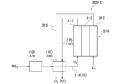
- FIG. 4 is a schematic diagram illustrating an ammonia fuel cell device according to one embodiment.
- FIG. 5 is a schematic diagram illustrating an ammonia-fired engine according to one embodiment.
- FIG. 6 is a schematic diagram showing an ammonia synthesis apparatus according to one embodiment.
- FIG. 7 is an SEM (scanning electron microscope) image showing that the measurement point of EDS (energy dispersive X-ray spectroscopy) is position A close to the outer surface of the modified layer.
- FIG. 8 is an SEM image showing that the EDS measurement location is position B of the modified layer close to the metal substrate.
- FIG. 9 is a graph comparing the nitride layer depths of the examples and the comparative examples.
- the ammonia handling device 1 includes an ammonia contact section 10.
- the ammonia contact section 10 includes a metal substrate 11 and a modified layer 12 that covers the metal substrate 11 and includes a ⁇ -phase NiAl intermetallic compound.
- the ammonia contact section 10 is configured so that ammonia comes into contact with the modified layer 12.
- the metal substrate 11 is not particularly limited, but may be, for example, nickel, iron, magnesium, aluminum, or an alloy containing these elements. As described below, in cases where the modified layer 12 is formed by a diffusion and penetration process, the metal substrate 11 is preferably nickel or a nickel alloy.
- the nickel alloy may be an alloy in which the nickel content is the highest by weight.
- the nickel alloy may contain 50% or more by weight of nickel.
- the nickel alloy may contain iron and chromium, and optionally at least one element selected from the group consisting of carbon, silicon, manganese, phosphorus, sulfur, nickel, molybdenum, cobalt, copper, tungsten, aluminum, titanium, niobium, tantalum, vanadium, rhenium, zirconium, boron, and nitrogen, with the balance being nickel and unavoidable impurities.
- the unavoidable impurities are elements other than those mentioned above, and may also include the above-mentioned optional elements.
- the total amount of unavoidable impurities contained in the nickel alloy may be 0.5% by weight or less, or may be 0.10% by weight or less.
- the content of each element of the unavoidable impurities contained in the nickel alloy may be 0.05% by weight or less, or may be 0.01% by weight or less.
- the iron content of the nickel alloy may be 1% by weight or more and 25% by weight or less.
- the iron content of the nickel alloy may be 3% by weight or more, or 5% by weight or more.
- the iron content of the nickel alloy may be 20% by weight or less, 16% by weight or less, or 12% by weight or less.
- the chromium content of the nickel alloy may be 1% by weight or more and 35% by weight or less.
- the chromium content of the nickel alloy may be 4% by weight or more, 8% by weight or more, or 12% by weight or more.
- the chromium content of the nickel alloy may be 30% by weight or less, 25% by weight or less, or 20% by weight or less.
- the modified layer 12 covers the metal substrate 11.
- the modified layer 12 may cover the surface of the metal substrate 11 and be in direct contact with the metal substrate 11.
- an intermediate layer (not shown), such as a platinum layer, may be provided between the metal substrate 11 and the modified layer 12, and the modified layer 12 may be in indirect contact with the metal substrate 11.
- the modified layer 12 is disposed between the metal substrate 11 and the ammonia.
- the modified layer 12 may cover at least a portion of the metal substrate 11 so that the metal substrate 11 does not come into contact with ammonia.
- the metal substrate 11 when there is a portion where the reactivity between the metal substrate 11 and ammonia is low, such as when the temperature of ammonia is low or the concentration of ammonia is low, the metal substrate 11 does not have to be covered with the modified layer 12 in that portion. That is, the modified layer 12 may cover only the portion where the reactivity between the metal substrate 11 and ammonia is high. Therefore, the modified layer 12 may cover only a portion of the metal substrate 11, or may cover the entire surface of the metal substrate 11.
- the modified layer 12 may be disposed on the outermost surface of the ammonia contact section 10.
- a ceramic layer (not shown) or the like may be provided on the surface of the modified layer 12 opposite the metal substrate 11.
- the modified layer 12 contains a ⁇ -phase NiAl intermetallic compound.
- the ⁇ -phase NiAl intermetallic compound has a higher effect of suppressing nitridation caused by ammonia than an intermetallic compound of iron and aluminum.
- the ⁇ -phase NiAl intermetallic compound has a higher effect of suppressing nitridation caused by ammonia than a ⁇ -phase (FCC solid solution) and a ⁇ '-phase (Ni 3 Al).
- the ⁇ -phase NiAl intermetallic compound has a high effect of suppressing nitridation caused by ammonia and is not easily nitrided even when in contact with ammonia, so that the nitridation of the metal substrate 11 can be suppressed by covering the metal substrate 11 with the modified layer 12.
- the modified layer 12 may be a single layer of a ⁇ -phase NiAl intermetallic compound.
- the ratio of the number of aluminum atoms to the total number of nickel and aluminum atoms is preferably 25% or more and 60% or less.
- a ⁇ -phase NiAl intermetallic compound can be generated in the modified layer 12.
- the ratio of the number of aluminum atoms to the total number of nickel and aluminum atoms may be 30% or more, 35% or more, or 40% or more.
- the ratio of the number of aluminum atoms to the total number of nickel and aluminum atoms may be 55% or less.
- the content of the ⁇ -phase NiAl intermetallic compound in the modified layer 12 may be 50% or more, 60% or more, 70% or more, or 80% or more in atomic ratio.
- the modified layer 12 may contain elements contained in the metal substrate 11 in addition to nickel and aluminum.
- the modified layer 12 may contain at least one element selected from the group consisting of carbon, silicon, manganese, phosphorus, sulfur, molybdenum, cobalt, copper, tungsten, titanium, niobium, tantalum, vanadium, rhenium, zirconium, boron, and nitrogen in addition to nickel and aluminum.
- the modified layer 12 may also contain a platinum group element such as platinum in addition to nickel and aluminum.
- the thickness of the modified layer 12 is preferably 10 ⁇ m or more and 100 ⁇ m or less. When the thickness of the modified layer 12 is 10 ⁇ m or more, nitridation can be more reliably suppressed. Furthermore, when the thickness of the modified layer 12 is 100 ⁇ m or less, the modified layer 12 can be easily formed on the metal substrate 11.
- the thickness of the modified layer 12 may be 15 ⁇ m or more, 20 ⁇ m or more, or 25 ⁇ m or more. Furthermore, the thickness of the modified layer 12 may be 80 ⁇ m or less, 60 ⁇ m or less, or 40 ⁇ m or less.
- the modified layer 12 can be formed by diffusing and penetrating aluminum into nickel or a nickel alloy using a diffusion and penetration process such as a pack method, a gas phase method, or a slurry method.
- a diffusion and penetration process such as a pack method, a gas phase method, or a slurry method.
- the aluminum concentration and thickness in the modified layer 12 can be adjusted by the concentration of the aluminum or aluminum alloy powder and the processing time, respectively.
- the modified layer 12 can also be formed on the surface of the metal substrate 11 by a method such as thermal spraying, build-up welding, plating, or powder spraying.
- the metal substrate 11 is not particularly limited and may be a metal other than nickel or a nickel alloy.
- a heat treatment may be performed.
- the conditions of the heat treatment are not particularly limited as long as a ⁇ -phase NiAl intermetallic compound can be generated, and may be, for example, 850°C or higher and 1100°C or lower. By setting the heat treatment temperature to 850°C or higher, NiAl intermetallic compounds are easily generated. In addition, by setting the heat treatment temperature to 1100°C or lower, the influence on the metal substrate 11 can be reduced.
- the heat treatment time may be, for example, 0.5 hours or more. By setting the heat treatment time to 0.5 hours or more, the thickness of the modified layer 12 can be increased.
- the thickness of the modified layer 12 tends to increase as the heat treatment time is increased, but once the modified layer 12 reaches a certain thickness, the thickness of the modified layer 12 does not depend so much on the time even if the heat treatment time is increased. Therefore, from the viewpoint of manufacturing efficiency, the upper limit of the heat treatment time may be 12 hours or less, 8 hours or less, or 6 hours or less.
- the ammonia contact section 10 includes the metal substrate 11 and the modified layer 12 has been described.
- the ammonia contact section 10 does not have to include the metal substrate 11. Even if the ammonia contact section 10 does not include the metal substrate 11, the modified layer 12 can suppress nitridation caused by ammonia.
- the ammonia contact section 10 that does not include the metal substrate 11 can be manufactured, for example, by melting a NiAl alloy.
- the ammonia contact section 10 that does not include the metal substrate 11 can be obtained by forming the modified layer 12 on the surface of a temporary substrate by a method such as powder spraying as described above, and then removing the temporary substrate. Such an ammonia contact section 10 may be subjected to heat treatment after forming the modified layer 12 as described above.
- the ammonia contact section 10 is configured so that ammonia comes into contact with the modified layer 12.
- the modified layer 12 is capable of suppressing nitridation caused by ammonia even at high temperatures, so the ammonia in contact with the modified layer 12 may be at least 200°C.
- the ammonia in contact with the modified layer 12 may be at least 300°C, at least 400°C, or at least 500°C.
- the ammonia in contact with the modified layer 12 may be at most 1000°C, for example.
- the ammonia handling apparatus 1 may be an ammonia combustion gas turbine, an ammonia combustion boiler, an ammonia combustion furnace, an ammonia fuel cell apparatus, an ammonia-fired engine, an ammonia synthesis apparatus, or a component included therein.
- the ammonia handling apparatus 1 will be described in detail below.
- the ammonia handling apparatus 1 is an ammonia combustion gas turbine 100.
- Fig. 2 is a schematic diagram showing the ammonia combustion gas turbine 100 according to one embodiment. As shown in Fig. 2, the ammonia combustion gas turbine 100 according to this embodiment includes a compressor 110, a combustion device 120, and a turbine 130.
- the compressor 110 takes in external air, compresses it, and supplies the compressed air to the combustion device 120.
- the compressor 110 is mechanically connected to the generator G and the turbine 130 via the rotating shaft 111.
- the combustion device 120 uses the air sent from the compressor 110 to burn fuel containing ammonia and generate combustion gas.
- the combustion device 120 includes a burner 121, a liner 126, a transition piece 127, and a casing 128.
- the burner 121 injects ammonia into the combustion chamber 140 and burns the ammonia.
- the burner 121 includes a supply pipe 122, a nozzle 123, an air supplier 124, and a liner head 125.
- the supply pipe 122 is connected to the nozzle 123, and fuel containing ammonia is supplied to the nozzle 123 from a fuel tank (not shown) through the supply pipe 122.
- the nozzle 123 injects the fuel containing ammonia into the combustion chamber 140.
- the air supplier 124 supplies air sent from the compressor 110 through an air flow path 141 into the combustion chamber 140.
- the liner head 125 is an upstream end wall that constitutes the combustion chamber 140. The burner 121 then combusts the fuel injected into the combustion chamber 140 to generate combustion gas.
- the combustion chamber 140 is formed by components including a liner 126 and a transition piece 127.
- the burner 121 is connected to the front end of the liner 126.
- the transition piece 127 is connected to the rear end of the liner 126 opposite the burner 121.
- the transition piece 127 connects the rear end of the liner 126 to the inlet of the turbine 130. Combustion gases generated in the combustion chamber 140 by the burner 121 are supplied to the turbine 130 via the transition piece 127.
- the turbine 130 includes turbine blades (not shown), which rotate as the combustion gas generated by the combustion device 120 passes through them.
- the turbine blades of the turbine 130 are mechanically connected to the compressor 110 via the rotating shaft 111. Therefore, as the turbine blades rotate, the rotation of the compressor 110 is promoted, driving the generator G to generate electricity.
- pre-combustion ammonia or unburned ammonia at high temperatures passes through the supply pipe 122, nozzle 123, liner head 125, liner 126, transition piece 127, and turbine 130. If ammonia comes into contact with the metal materials that make up these components, nitrides may be produced.
- the ammonia-burning gas turbine 100 is therefore equipped with an ammonia contact section 10.
- the components of the ammonia-burning gas turbine 100 namely, the supply pipe 122, the nozzle 123, the liner head 125, the liner 126, the transition piece 127 and the turbine 130, are equipped with the ammonia contact section 10.
- the ammonia contact section 10 includes a modified layer 12 containing a ⁇ -phase NiAl intermetallic compound, and is configured so that ammonia comes into contact with the modified layer 12. Therefore, the ammonia contact section 10 can suppress nitridation caused by ammonia.
- the ammonia combustion boiler 200 includes a furnace 210, a combustion gas horizontal movement section 220, a combustion gas descending section 230, and a burner 240.
- the furnace 210 extends in the vertical direction, and the combustion gas horizontal movement section 220 is connected to the upper part of the furnace 210, which is the downstream side of the furnace 210.
- the combustion gas horizontal movement section 220 extends horizontally from the upper part of the furnace 210.
- the combustion gas downward movement section 230 is downstream of the combustion gas horizontal movement section 220, and is connected to the end of the combustion gas horizontal movement section 220 opposite the furnace 210.
- the combustion gas downward movement section 230 extends downward from the end of the combustion gas horizontal movement section 220, and exhausts the combustion gas generated in the furnace 210 to the outside.
- a number of burners 240 are provided on the lower wall of the furnace 210.
- the burners 240 include nozzles and inject fuel containing ammonia into the furnace 210.
- the fuel injected from the burners 240 is burned in the furnace 210, generating high-temperature combustion gases.
- the fuel may also include a carbon-containing fuel such as pulverized coal.
- pre-combustion ammonia or unburned ammonia at high temperatures passes through the furnace 210, the combustion gas horizontal movement section 220, the combustion gas downward section 230, and the burner 240. If ammonia comes into contact with the metal materials that make up these components, nitrides may be produced.
- the ammonia combustion boiler 200 is therefore equipped with an ammonia contact section 10.
- the components included in the ammonia combustion boiler 200 namely the furnace 210, the combustion gas horizontal movement section 220, the combustion gas descending section 230 and the burner 240, are equipped with the ammonia contact section 10.
- the ammonia contact section 10 includes a reforming layer 12 containing a ⁇ -phase NiAl intermetallic compound, and is configured so that ammonia comes into contact with the reforming layer 12. Therefore, the ammonia contact section 10 can suppress nitridation caused by ammonia.
- an ammonia combustion furnace Similar to the ammonia combustion boiler 200, an ammonia combustion furnace such as an industrial furnace also includes a burner. Ammonia before combustion or unburned ammonia at a high temperature, such as 200° C. or higher, passes through the furnace and the burner. When ammonia comes into contact with the metal materials that constitute these, nitrides may be generated.
- the ammonia combustion furnace is therefore equipped with an ammonia contact section 10.
- the furnace and burner which are components included in the ammonia combustion furnace, are equipped with an ammonia contact section 10.
- the ammonia contact section 10 includes a modified layer 12 containing a ⁇ -phase NiAl intermetallic compound, and is configured so that ammonia comes into contact with the modified layer 12. Therefore, the ammonia contact section 10 can suppress nitridation caused by ammonia.
- ammonia fuel cell device 300 Next, an ammonia fuel cell device 300 according to this embodiment will be described with reference to Fig. 4. As shown in Fig. 4, the ammonia fuel cell device 300 includes a fuel cell main body 310, an ammonia decomposer 320, and a heat exchanger 330.
- the fuel cell main body 310 includes a fuel electrode 311, a cathode 312, and an electrolyte 313.
- the fuel cell main body 310 according to this embodiment is an SOFC.
- hydrogen is oxidized to generate an anode off-gas containing water (water vapor).
- oxygen ions move from the cathode 312 to the fuel electrode 311.
- the oxygen ions are reduced to generate a cathode off-gas containing oxygen.
- a fuel supply pipe 314 is connected to the inlet of the fuel electrode 311, and hydrogen is supplied to the fuel electrode 311.
- An ammonia decomposer 320 and a heat exchanger 330 are provided in the fuel supply pipe 314, and ammonia is supplied from a tank (not shown) that contains ammonia to the ammonia decomposer 320 and the heat exchanger 330 and decomposed to generate hydrogen.
- An anode exhaust pipe 315 is connected to the outlet of the fuel electrode 311, and anode off-gas generated at the fuel electrode 311 is exhausted from within the fuel cell main body 310.
- a heat exchanger 330 is provided in the anode exhaust pipe 315.
- a cathode exhaust pipe 316 is connected to the outlet of the air electrode 312, and cathode off-gas generated at the air electrode 312 is exhausted from within the fuel cell main body 310.
- a heat exchanger 330 is provided in the cathode exhaust pipe 316.
- the ammonia decomposer 320 decomposes ammonia to produce hydrogen.
- the ammonia decomposer 320 contains an ammonia decomposition catalyst, such as a ruthenium catalyst or a nickel catalyst, in a container, and when ammonia comes into contact with the catalyst at a temperature of, for example, 400°C or higher and 800°C or lower, it is decomposed into hydrogen and nitrogen.
- an ammonia decomposition catalyst such as a ruthenium catalyst or a nickel catalyst
- the heat exchanger 330 is connected to the fuel supply pipe 314, the anode exhaust pipe 315, and the cathode exhaust pipe 316.
- the heat exchanger 330 exchanges the heat of the anode off-gas discharged from the fuel electrode 311 and the heat of the cathode off-gas discharged from the air electrode 312 with the heat of the fuel supplied to the fuel electrode 311 from the ammonia decomposer 320 via the fuel supply pipe 314.
- the fuel contains ammonia that was not decomposed in the ammonia decomposer 320 and remains there, and the above-mentioned ammonia decomposition catalyst that decomposes ammonia is disposed in the flow path through which the fuel passes in the heat exchanger 330. Therefore, the heat exchanger 330 decomposes the ammonia remaining in the fuel to generate hydrogen.
- pre-combustion ammonia or unburned ammonia at high temperatures passes through the fuel cell main body 310, ammonia decomposer 320, heat exchanger 330, fuel supply pipe 314, and anode exhaust pipe 315. If ammonia comes into contact with the metal materials that make up these components, nitrides may be produced.
- the ammonia fuel cell device 300 is therefore equipped with an ammonia contact section 10.
- the components included in the ammonia fuel cell device 300 namely the fuel cell main body 310, the ammonia decomposer 320, the heat exchanger 330, the fuel supply pipe 314 and the anode exhaust pipe 315, are equipped with the ammonia contact section 10.
- the ammonia contact section 10 includes a reforming layer 12 containing a ⁇ -phase NiAl intermetallic compound, and is configured so that ammonia comes into contact with the reforming layer 12. Therefore, the ammonia contact section 10 can suppress nitridation caused by ammonia.
- the ammonia-fired engine 400 includes a cylinder block 410, a cylinder head 420, and a piston 430.
- the cylinder block 410 has a cylinder 411.
- the piston 430 is disposed within the cylinder 411.
- a combustion chamber 440 is disposed within the cylinder 411, between the cylinder head 420 and the piston 430.
- the cylinder head 420 is provided with an injection unit 421 that injects fuel containing ammonia into the combustion chamber 440.
- the cylinder head 420 has an intake port 422 and an exhaust port 423 that communicate with the combustion chamber 440.
- the cylinder head 420 is provided with an intake valve 424 that can open and close the intake port 422 of the cylinder head 420 from the combustion chamber 440 side. When the intake valve 424 is opened, air is supplied to the combustion chamber 440 through the intake port 422.
- the cylinder head 420 is also provided with an exhaust valve 425 that can open and close the exhaust port 423 of the cylinder head 420 from the combustion chamber 440 side. When the exhaust valve 425 is opened, exhaust gas generated by the combustion of fuel in the combustion chamber 440 is discharged to the outside of the ammonia-fired engine 400 through the exhaust port 423.
- pre-combustion ammonia or unburned ammonia at high temperatures passes through the cylinder 411, exhaust port 423, intake valve 424, exhaust valve 425, and piston 430. If ammonia comes into contact with the metal materials that make up these components, nitrides may be produced.
- the ammonia-fired engine 400 is therefore equipped with an ammonia contact section 10.
- the components of the ammonia-fired engine 400 namely the cylinder 411, the exhaust port 423, the intake valve 424, the exhaust valve 425 and the piston 430, are equipped with the ammonia contact section 10.
- the ammonia contact section 10 includes a modified layer 12 containing a ⁇ -phase NiAl intermetallic compound, and is configured so that ammonia comes into contact with the modified layer 12. Therefore, the ammonia contact section 10 can suppress nitridation caused by ammonia.
- the ammonia synthesis apparatus 500 includes a raw material supply section 510 and a reactor 520.
- the raw material supply unit 510 supplies nitrogen and hydrogen, which are raw materials for ammonia, to the reactor 520.
- the raw material supply unit 510 supplies a mixed raw material containing ammonia and nitrogen to the reactor 520 via the raw material supply piping 530.
- the raw material supply unit 510 may include an ammonia supply unit that supplies ammonia to the reactor 520, and a nitrogen supply unit that supplies nitrogen to the reactor 520.
- the reactor 520 produces ammonia from raw materials containing nitrogen and hydrogen supplied from the raw material supply unit 510.
- the reactor 520 contains an ammonia catalyst structure 525 that produces ammonia from nitrogen and hydrogen.
- the production of ammonia is promoted by contacting the raw materials containing nitrogen and hydrogen with the ammonia catalyst structure 525.
- the type of the reactor 520 and the reaction conditions within the reactor 520 are not particularly limited.
- the ammonia produced in the reactor 520 is discharged from the reactor 520 through an exhaust pipe 531.
- the ammonia catalyst structure 525 includes a catalyst such as an iron-based catalyst, a metal carrier that supports the catalyst, and a metal casing that houses the catalyst and the metal carrier.
- a catalyst such as an iron-based catalyst
- a metal carrier that supports the catalyst
- a metal casing that houses the catalyst and the metal carrier.
- pre-combustion ammonia or unburned ammonia at high temperatures passes through the reactor 520, the ammonia catalyst structure 525, and the exhaust pipe 531. If ammonia comes into contact with the metal materials that make up these components, nitrides may be produced.
- the ammonia synthesis apparatus 500 is therefore equipped with an ammonia contact section 10.
- the components included in the ammonia synthesis apparatus 500 that is, the reactor 520, the metal carrier and metal casing included in the ammonia catalyst structure 525, and the exhaust pipe 531, are equipped with the ammonia contact section 10.
- the ammonia contact section 10 includes a reforming layer 12 containing a ⁇ -phase NiAl intermetallic compound, and is configured so that ammonia comes into contact with the reforming layer 12. Therefore, the ammonia contact section 10 can suppress nitridation caused by ammonia.
- the ammonia handling device 1 includes a reforming layer 12 containing a ⁇ -phase NiAl intermetallic compound, and is equipped with an ammonia contact section 10 configured so that ammonia comes into contact with the reforming layer 12.
- Beta-phase NiAl intermetallic compounds have a high effect of suppressing nitridation caused by ammonia, and are not easily nitrided even when in contact with ammonia. Therefore, the ammonia handling device 1 according to this embodiment can suppress nitridation caused by ammonia.
- ALLOY600 is an alloy containing 16 wt% Cr and 8 wt% Fe, with the balance being Ni and unavoidable impurities.
- a mixed powder containing an aluminum alloy powder, alumina as a sintering inhibitor, and ammonium chloride as an activator was also prepared.
- the nickel alloy was buried in the mixed powder and heated at around 900°C for about 1.5 hours, and a diffusion and penetration process was carried out to diffuse aluminum into the surface of the nickel alloy using the pack cementation method, obtaining the sample for this example.
- FIG. 7 is an SEM image showing that the EDS measurement location was position A, which is close to the outer surface of the modified layer.
- Figure 8 is an SEM image showing that the EDS measurement location was position B, which is close to the metal substrate of the modified layer.
- Table 1 shows the EDS measurement results at position A.
- Table 2 shows the EDS measurement results at position B.
- Comparative Example 1 A sample was obtained in the same manner as in the example, except that the nickel alloy ALLOY600 was replaced with a stainless steel SUS310S containing 25% by weight of Cr and 20% by weight of Ni, with the balance being Fe and unavoidable impurities.
- ALLOY738LC contains 8.5% by weight of cobalt, 16.0% by weight of chromium, 1.8% by weight of molybdenum, 2.6% by weight of tungsten, 1.8% by weight of tantalum, 3.4% by weight of aluminum, 3.4% by weight of titanium, 0.9% by weight of niobium, 0.10% by weight of carbon, 0.010% by weight of boron, and 0.060% by weight of zirconium, with the balance being nickel and inevitable impurities.
- ALLOY738LC is a nickel alloy in which the ratio of the number of aluminum atoms to the total number of nickel and aluminum atoms is about 11%, and it is known to contain ⁇ phase and ⁇ ' phase. With such an aluminum ratio, unlike the sample of the example, ⁇ phase does not appear.
- the nitridation of the sample of Comparative Example 1 was slightly suppressed compared to the sample of Comparative Example 2, or was almost the same.
- the nitridation of the sample of Comparative Example 3 was suppressed compared to the samples of Comparative Examples 1 and 2, but the nitridation of the sample of the Example was suppressed even more, with the nitride layer depth being below the detection limit.
- the ⁇ -phase NiAl intermetallic compound can further suppress nitridation caused by ammonia compared to the ⁇ -phase and ⁇ '-phase. From these results, it is considered that nitridation caused by ammonia can be suppressed by generating a dense aluminum nitride layer in the ⁇ -phase, even when exposed to a high-temperature ammonia environment.
Landscapes
- Chemical & Material Sciences (AREA)
- Organic Chemistry (AREA)
- Engineering & Computer Science (AREA)
- Materials Engineering (AREA)
- Mechanical Engineering (AREA)
- Metallurgy (AREA)
- Chemical Kinetics & Catalysis (AREA)
- Physics & Mathematics (AREA)
- Plasma & Fusion (AREA)
- Inorganic Chemistry (AREA)
- Solid-Phase Diffusion Into Metallic Material Surfaces (AREA)
- Catalysts (AREA)
Abstract
Description
まず、アンモニア取扱装置1が、アンモニア燃焼ガスタービン100である例について説明する。図2は、一実施形態に係るアンモニア燃焼ガスタービン100を示す概略図である。図2に示すように、本実施形態に係るアンモニア燃焼ガスタービン100は、圧縮機110と、燃焼装置120と、タービン130とを備えている。
次に、本実施形態に係るアンモニア燃焼ボイラ200について図3を用いて説明する。図3に示すように、本実施形態に係るアンモニア燃焼ボイラ200は、火炉210と、燃焼ガス水平移動部220と、燃焼ガス下降部230と、バーナ240とを備えている。
アンモニア燃焼ボイラ200と同様に、工業炉のようなアンモニア燃焼炉もバーナを含んでいる。そして、炉及びバーナには、200℃以上のような高温の燃焼前のアンモニア又は未燃焼のアンモニアが通過する。アンモニアとこれらを構成する金属材料とが接すると、窒化物が生成されるおそれがある。
次に、本実施形態に係るアンモニア燃料電池装置300について図4を用いて説明する。図4に示すように、アンモニア燃料電池装置300は、燃料電池本体310と、アンモニア分解器320と、熱交換器330とを備えている。
次に、アンモニア焚きエンジン400について図5を用いて説明する。図5に示すように、アンモニア焚きエンジン400は、シリンダブロック410と、シリンダヘッド420と、ピストン430と、を備えている。シリンダブロック410はシリンダ411を有している。シリンダ411内には、ピストン430が配置されている。シリンダ411内部であって、シリンダヘッド420とピストン430との間には、燃焼室440が配置されている。
次に、アンモニア合成装置500について図6を用いて説明する。図6に示すように、アンモニア合成装置500は、原料供給部510と、反応器520とを備えている。
まず、ALLOY600のニッケル合金を準備した。ALLOY600は、Crを16重量%及びFeを8重量%含み、残部がNi及び不可避不純物の合金である。また、アルミニウム合金粉末、焼結防止剤としてのアルミナ、及び活性剤としての塩化アンモニウムを含む混合粉末を準備した。


ALLOY600のニッケル合金に代え、25重量%のCr及び20重量%のNiを含み、残部がFe及び不可避不純物であるSUS310Sのステンレス鋼を用いた以外は、実施例と同様にして試料を得た。
拡散浸透処理を実施せず、実施例で用いたALLOY600を本例に係る試料とした。
拡散浸透処理を実施せず、ALLOY738LCを本例に係る試料とした。ALLOY738LCは、8.5重量%のコバルト、16.0重量%のクロム、1.8重量%のモリブデン、2.6重量%のタングステン、1.8重量%のタンタル、3.4重量%のアルミニウム、3.4重量%のチタン、0.9重量%のニオブ、0.10重量%の炭素、0.010重量%のホウ素及び0.060重量%のジルコニウムを含み、残部がニッケル及び不可避不純物である。なお、ALLOY738LCは、ニッケル及びアルミニウムの原子数の合計に対するアルミニウムの原子数の割合が約11%のニッケル合金であり、γ相及びγ’相を含んでいることが知られている。このようなアルミニウム比では、実施例の試料とは異なり、β相は出現しない。
(アンモニア暴露試験)
上記のようにして得られた試料を、アンモニアが飽和した状態で、500℃で100時間曝露させた。アンモニア暴露試験後の試料を切断し、その切断面の窒化層深さを、光学顕微鏡で観察した。この結果を図9に示す。
10 アンモニア接触部
11 金属基材
12 改質層
Claims (6)
- β相NiAl金属間化合物を含む改質層を含み、アンモニアが前記改質層と接するように構成されたアンモニア接触部を備える、アンモニア取扱装置。
- 前記アンモニア接触部は金属基材を含み、
前記改質層は前記金属基材を覆う、請求項1に記載のアンモニア取扱装置。 - 前記金属基材はニッケル又はニッケル合金である、請求項2に記載のアンモニア取扱装置。
- 前記改質層と接触するアンモニアは200℃以上である、請求項1~3のいずれか一項に記載のアンモニア取扱装置。
- 前記アンモニア取扱装置は、アンモニア燃焼ガスタービン、アンモニア燃焼ボイラ、アンモニア燃焼炉、アンモニア燃料電池装置、アンモニア焚きエンジン、アンモニア合成装置、又は、これらに含まれる構成要素である、請求項1~4のいずれか一項に記載のアンモニア取扱装置。
- 請求項1~5のいずれか一項に記載のアンモニア取扱装置の製造方法であって、
前記改質層は、ニッケル又はニッケル合金に、アルミニウムを拡散浸透させることによって形成する、アンモニア取扱装置の製造方法。
Priority Applications (4)
| Application Number | Priority Date | Filing Date | Title |
|---|---|---|---|
| JP2025516529A JPWO2024224741A1 (ja) | 2023-04-27 | 2024-02-07 | |
| CN202480024986.8A CN121013914A (zh) | 2023-04-27 | 2024-02-07 | 氨处理装置及其制造方法 |
| EP24796500.7A EP4703495A1 (en) | 2023-04-27 | 2024-02-07 | Ammonia handling device and method for producing same |
| US19/368,494 US20260048994A1 (en) | 2023-04-27 | 2025-10-24 | Ammonia handling device and method of manufacturing thereof |
Applications Claiming Priority (2)
| Application Number | Priority Date | Filing Date | Title |
|---|---|---|---|
| JP2023073374 | 2023-04-27 | ||
| JP2023-073374 | 2023-04-27 |
Related Child Applications (1)
| Application Number | Title | Priority Date | Filing Date |
|---|---|---|---|
| US19/368,494 Continuation US20260048994A1 (en) | 2023-04-27 | 2025-10-24 | Ammonia handling device and method of manufacturing thereof |
Publications (1)
| Publication Number | Publication Date |
|---|---|
| WO2024224741A1 true WO2024224741A1 (ja) | 2024-10-31 |
Family
ID=93255893
Family Applications (1)
| Application Number | Title | Priority Date | Filing Date |
|---|---|---|---|
| PCT/JP2024/004055 Ceased WO2024224741A1 (ja) | 2023-04-27 | 2024-02-07 | アンモニア取扱装置及びその製造方法 |
Country Status (5)
| Country | Link |
|---|---|
| US (1) | US20260048994A1 (ja) |
| EP (1) | EP4703495A1 (ja) |
| JP (1) | JPWO2024224741A1 (ja) |
| CN (1) | CN121013914A (ja) |
| WO (1) | WO2024224741A1 (ja) |
Citations (7)
| Publication number | Priority date | Publication date | Assignee | Title |
|---|---|---|---|---|
| JPH06114236A (ja) | 1992-08-18 | 1994-04-26 | Mitsubishi Heavy Ind Ltd | アンモニアの分解防止方法 |
| JPH10219426A (ja) * | 1997-02-04 | 1998-08-18 | Ebara Corp | 半導体製造プロセス用部材 |
| JP2006504867A (ja) * | 2002-02-28 | 2006-02-09 | サンドビック インテレクチュアル プロパティー ハンデルスボラーグ | メタルダスティングに耐性を有する銅基合金及びその使用 |
| JP2007530263A (ja) * | 2004-03-23 | 2007-11-01 | ヴェロシス インコーポレイテッド | マイクロチャネル装置における調整された均一なコーティング |
| CN103526204A (zh) * | 2013-10-15 | 2014-01-22 | 云南大学 | 阳极氧化在合金表面制备耐热冲击的功能氧化物层 |
| CN211513932U (zh) * | 2019-12-02 | 2020-09-18 | 中节能工业节能有限公司 | 金属间化合物柔性膜除尘器和高温除尘装置 |
| JP2023073374A (ja) | 2019-03-13 | 2023-05-25 | セイコーエプソン株式会社 | 液体噴射装置 |
-
2024
- 2024-02-07 CN CN202480024986.8A patent/CN121013914A/zh active Pending
- 2024-02-07 EP EP24796500.7A patent/EP4703495A1/en active Pending
- 2024-02-07 WO PCT/JP2024/004055 patent/WO2024224741A1/ja not_active Ceased
- 2024-02-07 JP JP2025516529A patent/JPWO2024224741A1/ja active Pending
-
2025
- 2025-10-24 US US19/368,494 patent/US20260048994A1/en active Pending
Patent Citations (7)
| Publication number | Priority date | Publication date | Assignee | Title |
|---|---|---|---|---|
| JPH06114236A (ja) | 1992-08-18 | 1994-04-26 | Mitsubishi Heavy Ind Ltd | アンモニアの分解防止方法 |
| JPH10219426A (ja) * | 1997-02-04 | 1998-08-18 | Ebara Corp | 半導体製造プロセス用部材 |
| JP2006504867A (ja) * | 2002-02-28 | 2006-02-09 | サンドビック インテレクチュアル プロパティー ハンデルスボラーグ | メタルダスティングに耐性を有する銅基合金及びその使用 |
| JP2007530263A (ja) * | 2004-03-23 | 2007-11-01 | ヴェロシス インコーポレイテッド | マイクロチャネル装置における調整された均一なコーティング |
| CN103526204A (zh) * | 2013-10-15 | 2014-01-22 | 云南大学 | 阳极氧化在合金表面制备耐热冲击的功能氧化物层 |
| JP2023073374A (ja) | 2019-03-13 | 2023-05-25 | セイコーエプソン株式会社 | 液体噴射装置 |
| CN211513932U (zh) * | 2019-12-02 | 2020-09-18 | 中节能工业节能有限公司 | 金属间化合物柔性膜除尘器和高温除尘装置 |
Non-Patent Citations (1)
| Title |
|---|
| See also references of EP4703495A1 |
Also Published As
| Publication number | Publication date |
|---|---|
| EP4703495A1 (en) | 2026-03-04 |
| US20260048994A1 (en) | 2026-02-19 |
| JPWO2024224741A1 (ja) | 2024-10-31 |
| CN121013914A (zh) | 2025-11-25 |
Similar Documents
| Publication | Publication Date | Title |
|---|---|---|
| JP4383499B2 (ja) | 耐酸化性合金皮膜、耐酸化性合金皮膜の製造方法および耐熱性金属部材 | |
| Pint | Optimization of reactive‐element additions to improve oxidation performance of alumina‐forming alloys | |
| Sidhu et al. | Hot corrosion and performance of nickel-based coatings | |
| US9249482B2 (en) | Nickel-chromium-alloy | |
| EP3476970A1 (en) | Austenitic alloy material and austenitic alloy pipe | |
| Shao et al. | Temperature-dependent and duration-dependent effect on the growth behavior of CVD aluminide coating on K452 superalloy | |
| Zhai et al. | Effect of β phase size on the microstructure of thermally grown oxide in water vapor atmosphere at 1100° C | |
| WO2024224741A1 (ja) | アンモニア取扱装置及びその製造方法 | |
| Subanovic et al. | Blistering of MCrAlY-coatings in H2/H2O-atmospheres | |
| JP6846838B2 (ja) | 耐熱合金部材の製造方法、合金皮膜の製造方法および高温装置の製造方法 | |
| JP2003277976A (ja) | 耐熱部材およびその製造方法 | |
| Zhang et al. | The corrosion behavior of four commercial steels in reducing atmospheres containing HCl at 773–873 K | |
| Kochmańska et al. | Failure analysis of grate in a municipal solid waste incineration plant | |
| JP2002332563A (ja) | 合金皮膜、該皮膜を有する耐熱部材およびその製造方法 | |
| Schaeffer et al. | The effects of precious metals on the oxidation and hot corrosion of coatings | |
| Nowak et al. | Effect of Mo addition on the oxidation behavior of the AlCoCrFeNi high entropy alloy | |
| Xu et al. | Impact of iron and chromium on coal ash corrosion behavior of Ni-Cr-Co based alloy for advanced ultra-supercritical power plants | |
| Fomina et al. | Effect of hydrogen on nickel oxide reduction on the surface of nozzle blade of a gas turbine unit | |
| Nowak et al. | High-temperature protective coatings and methods of their analysis | |
| Ilinich et al. | Oxidation Performance of Fe-Ni-Co-Cr-Mn High Entropy Alloy and its Al-Containing Variants in Supercritical CO2 | |
| Stroosnijder | Use of ion implantation in high temperature corrosion studies | |
| Alnaeli et al. | High-temperature degradation of Hastelloy C276 in methane and 99% cracked ammonia combustion: surface analysis and mechanical property evolution at 4 bar | |
| JP3212469B2 (ja) | 耐高温酸化性表面処理方法 | |
| Toh | Metal dusting on heat-resistant alloys under thermal cyclic conditions | |
| JP2961033B2 (ja) | 空冷翼及びその製法 |
Legal Events
| Date | Code | Title | Description |
|---|---|---|---|
| 121 | Ep: the epo has been informed by wipo that ep was designated in this application |
Ref document number: 24796500 Country of ref document: EP Kind code of ref document: A1 |
|
| ENP | Entry into the national phase |
Ref document number: 2025516529 Country of ref document: JP Kind code of ref document: A |
|
| WWE | Wipo information: entry into national phase |
Ref document number: 2025516529 Country of ref document: JP |
|
| WWE | Wipo information: entry into national phase |
Ref document number: 2024796500 Country of ref document: EP |
|
| NENP | Non-entry into the national phase |
Ref country code: DE |
|
| ENP | Entry into the national phase |
Ref document number: 2024796500 Country of ref document: EP Effective date: 20251127 |
|
| ENP | Entry into the national phase |
Ref document number: 2024796500 Country of ref document: EP Effective date: 20251127 |
|
| ENP | Entry into the national phase |
Ref document number: 2024796500 Country of ref document: EP Effective date: 20251127 |
|
| ENP | Entry into the national phase |
Ref document number: 2024796500 Country of ref document: EP Effective date: 20251127 |
|
| ENP | Entry into the national phase |
Ref document number: 2024796500 Country of ref document: EP Effective date: 20251127 |
|
| ENP | Entry into the national phase |
Ref document number: 2024796500 Country of ref document: EP Effective date: 20251127 |
|
| ENP | Entry into the national phase |
Ref document number: 2024796500 Country of ref document: EP Effective date: 20251127 |
|
| ENP | Entry into the national phase |
Ref document number: 2024796500 Country of ref document: EP Effective date: 20251127 |
|
| ENP | Entry into the national phase |
Ref document number: 2024796500 Country of ref document: EP Effective date: 20251127 |
|
| WWP | Wipo information: published in national office |
Ref document number: 2024796500 Country of ref document: EP |