WO2024228294A1 - 分析装置、分析方法及び分析プログラム - Google Patents
分析装置、分析方法及び分析プログラム Download PDFInfo
- Publication number
- WO2024228294A1 WO2024228294A1 PCT/JP2024/007990 JP2024007990W WO2024228294A1 WO 2024228294 A1 WO2024228294 A1 WO 2024228294A1 JP 2024007990 W JP2024007990 W JP 2024007990W WO 2024228294 A1 WO2024228294 A1 WO 2024228294A1
- Authority
- WO
- WIPO (PCT)
- Prior art keywords
- records
- key
- unit
- analysis
- data
- Prior art date
- Legal status (The legal status is an assumption and is not a legal conclusion. Google has not performed a legal analysis and makes no representation as to the accuracy of the status listed.)
- Ceased
Links
Images


Classifications
-
- G—PHYSICS
- G06—COMPUTING OR CALCULATING; COUNTING
- G06F—ELECTRIC DIGITAL DATA PROCESSING
- G06F16/00—Information retrieval; Database structures therefor; File system structures therefor
- G06F16/20—Information retrieval; Database structures therefor; File system structures therefor of structured data, e.g. relational data
- G06F16/21—Design, administration or maintenance of databases
- G06F16/215—Improving data quality; Data cleansing, e.g. de-duplication, removing invalid entries or correcting typographical errors
-
- G—PHYSICS
- G06—COMPUTING OR CALCULATING; COUNTING
- G06F—ELECTRIC DIGITAL DATA PROCESSING
- G06F16/00—Information retrieval; Database structures therefor; File system structures therefor
- G06F16/20—Information retrieval; Database structures therefor; File system structures therefor of structured data, e.g. relational data
- G06F16/28—Databases characterised by their database models, e.g. relational or object models
- G06F16/284—Relational databases
-
- G—PHYSICS
- G06—COMPUTING OR CALCULATING; COUNTING
- G06F—ELECTRIC DIGITAL DATA PROCESSING
- G06F16/00—Information retrieval; Database structures therefor; File system structures therefor
- G06F16/20—Information retrieval; Database structures therefor; File system structures therefor of structured data, e.g. relational data
- G06F16/24—Querying
-
- G—PHYSICS
- G06—COMPUTING OR CALCULATING; COUNTING
- G06F—ELECTRIC DIGITAL DATA PROCESSING
- G06F21/00—Security arrangements for protecting computers, components thereof, programs or data against unauthorised activity
- G06F21/60—Protecting data
- G06F21/62—Protecting access to data via a platform, e.g. using keys or access control rules
- G06F21/6218—Protecting access to data via a platform, e.g. using keys or access control rules to a system of files or objects, e.g. local or distributed file system or database
- G06F21/6227—Protecting access to data via a platform, e.g. using keys or access control rules to a system of files or objects, e.g. local or distributed file system or database where protection concerns the structure of data, e.g. records, types, queries
-
- G—PHYSICS
- G06—COMPUTING OR CALCULATING; COUNTING
- G06F—ELECTRIC DIGITAL DATA PROCESSING
- G06F21/00—Security arrangements for protecting computers, components thereof, programs or data against unauthorised activity
- G06F21/60—Protecting data
- G06F21/62—Protecting access to data via a platform, e.g. using keys or access control rules
- G06F21/6218—Protecting access to data via a platform, e.g. using keys or access control rules to a system of files or objects, e.g. local or distributed file system or database
- G06F21/6245—Protecting personal data, e.g. for financial or medical purposes
-
- G—PHYSICS
- G09—EDUCATION; CRYPTOGRAPHY; DISPLAY; ADVERTISING; SEALS
- G09C—CIPHERING OR DECIPHERING APPARATUS FOR CRYPTOGRAPHIC OR OTHER PURPOSES INVOLVING THE NEED FOR SECRECY
- G09C1/00—Apparatus or methods whereby a given sequence of signs, e.g. an intelligible text, is transformed into an unintelligible sequence of signs by transposing the signs or groups of signs or by replacing them by others according to a predetermined system
Definitions
- the present invention relates to an analysis device, an analysis method, and an analysis program.
- Secure computation systems are known that perform statistical calculations while keeping data secret, and provide users with the statistics obtained as a result of the calculations.
- secure computation systems are sometimes used to analyze data in fields such as the medical field, which handles important personal information.
- Patent Document 3 a method for manipulating tables using secure computation is known (see, for example, Patent Document 3).
- FIG. 6 is a diagram explaining the conventional procedure for deleting duplicates.
- records with duplicates in the "Employee ID" column and the "Department Code” column (hereinafter referred to as the duplicate deletion key) are deleted except for one. Therefore, record group 61a and record group 62a in table 51a in FIG. 6 are the targets of duplicate deletion.
- Records included in the set of records to be deleted for duplicate deletion share a common duplicate deletion key, but have different values in the "Entry Date" column, for example. For this reason, when deleting duplicates, there may be a desire to keep the record with the most recent "Entry Date,” for example.
- the records to be deleted from the set of records to be deleted may be determined randomly. As a result, after duplicate deletion, the desired records may not remain.
- the analysis device of the present invention is characterized by having a sorting unit that sorts records of a table including records with duplicate values of a first key by a second key different from the first key through secret calculation, and a deletion unit that deletes, through secret calculation, all records except for one record located at a predetermined position in each set of records with duplicate values of the first key included in the table sorted by the sorting unit.
- FIG. 1 is a diagram illustrating an example of the configuration of an analysis system according to an embodiment.
- FIG. 2 is a diagram illustrating an example of the configuration of the analysis device according to the embodiment.
- FIG. 3 is a diagram illustrating a procedure for deleting duplicates according to the embodiment.
- FIG. 4 is a flowchart showing a process flow of the analysis device according to the embodiment.
- FIG. 5 is a diagram illustrating an example of a computer that executes an analysis program.
- FIG. 6 is a diagram for explaining a conventional procedure for deleting duplicates.
- the analysis system is a system for analyzing data using secure computation.
- the analysis system 1 includes a secure computation system 10.
- the secure computation system 10 is also connected to a providing device 20 and a providing device 30 via a network N.
- the network N is the Internet.
- the secure computation system 10 is also connected to a terminal device 40.
- the providing device 20 and the providing device 30 are devices on the data provider side.
- the providing device 20 and the providing device 30 provide (register) data to the secure computing system 10.
- the data provided by the providing device 20 and the providing device 30 includes information that is desired to be kept confidential (e.g., personal information such as an individual's name and address).
- the providing device 20 and the providing device 30 provide data related to medical receipts and DPCs (Diagnosis Procedure Combinations) used in medical institutions.
- the secure computation system 10 has a data storage unit 11 and a data processing unit 12.
- the data storage unit 11 includes a plurality of storage devices (storage device 111, storage device 112, storage device 113) that store data by secret sharing.
- the data processing unit 12 includes a plurality of computation devices (computation device 121, computation device 122, computation device 123) that process data by secure computation. Note that the number of storage devices and the number of computation devices are not limited to the example shown in FIG. 1.
- the secure computation system 10 can perform secret sharing and secure computation according to the method described in Non-Patent Document 1 (URL: https://www.rd.ntt/sil/project/sc/secure_computation.html).
- the data provided to the secure computing system 10 is divided (fragmented) into multiple shares. Then, each of the multiple shares is distributed and stored in multiple storage devices included in the data storage unit 11. In the example of FIG. 1, the provided data is divided into three shares. Then, storage device 111, storage device 112, and storage device 113 each store one share.
- the data processing unit 12 performs secure computation on the shares accumulated in the data accumulation unit 11.
- the data processing unit 12 performs secure computation by multi-party computation using multiple computing devices.
- the data processing unit 12 performs secure computation by computing device 121, computing device 122, and computing device 123.
- the data processing unit 12 can perform various statistical calculations without restoring the shares.
- the data processing unit 12 can perform table operations such as sorting and joining, tallying the number of records, calculating statistics such as sums, averages, maximum values, minimum values, and sample variances, and performing statistical tests such as t-tests.
- the data processing unit 12 can perform statistical analyses such as regression analysis and principal component analysis.
- the analysis device 13 uses the data processing unit 12 to analyze the data.
- the analysis device 13 provides the analysis result to the terminal device 40 on the data user side based on the result of the secret calculation executed by the data processing unit 12. The user can obtain the data analysis result via the terminal device 40.
- the secure computing system 10 may be provided with data on the attributes and physical condition of each individual.
- the data on the attributes and physical condition is personal information that is preferably kept confidential.
- the data on the attributes and physical condition includes, for example, age, sex, height, weight, etc.
- the data storage unit 11 stores fragmented shares of the provided data in each storage device.
- each divided share is meaningless data on its own. Therefore, it is not possible to restore the original data from a single share. However, by collecting multiple shares, it is possible to restore the original data.
- the user of the data cannot view the registered data itself, but can view the results of the analysis of the data via the analysis device 13 and the terminal device 40.
- the data includes the gender and weight of individuals, the user cannot view the gender and weight of each individual, but can view the "average weight of men," which is the result of the analysis of the data.
- the data storage unit 11 can perform secret sharing using a technique known as Shamir's threshold secret sharing method.
- the data storage unit 11 stores three coordinates that pass through a polynomial with the original data as an intercept in each server as shares. Furthermore, since the slope of the polynomial is determined randomly, the shares are not necessarily the same each time even if the original data is the same.
- the original data may be a numeric value, or may be data that has already been converted into a numeric value.
- the secure computing system 10 can restore the original data from multiple shares. If the polynomial is a linear expression, the secure computing system 10 can find the intercept (corresponding to the original data) from the intersection of the axis and a straight line connecting two coordinates (corresponding to shares). On the other hand, since a straight line cannot be determined from a single coordinate, the original data cannot be restored.
- the data processing unit 12 can perform secure computation on the original data without restoring the shares.
- the result of adding the shares represented by coordinates corresponds to the share resulting from adding the original data of each share.
- the analysis device 13 In response to a request from the terminal device 40, the analysis device 13 causes the data processing unit 12 to execute processing using secret calculations.
- the data processing unit 12 or the terminal device 40 may realize functions equivalent to those of the analysis device 13.
- the analysis system 1 may be configured without the analysis device 13.
- the terminal device 40 is connected to the data processing unit 12 and executes processing equivalent to that of the analysis device 13.
- statistical calculations based on shares may be executed by the terminal device 40 rather than the data processing unit 12.
- the table that the analysis device 13 performs duplicate deletion on is, for example, a table included in a relational database (RDB) in which multiple tables are associated.
- RDB relational database
- the conventional technology has a problem in that it may not be possible to specify which records to keep when deleting duplicates.
- the analysis device 13 of the first embodiment can delete duplicates in a table using secure computation while leaving the specified records.
- FIG. 2 is a diagram showing an example of the configuration of the analysis device according to an embodiment.
- the analysis device 13 has a communication unit 131, an input unit 132, an output unit 133, a memory unit 134, and a control unit 135.
- the communication unit 131 communicates data with other devices.
- the communication unit 131 is a NIC (Network Interface Card).
- the communication unit 131 can send and receive data with other devices.
- the input unit 132 is an interface for accepting data input.
- the input unit 132 is connected to input devices such as a mouse and a keyboard.
- the output unit 133 is an interface for outputting data.
- the output unit 133 is connected to input devices such as a display and a speaker.
- the memory unit 134 is a storage device such as a hard disk drive (HDD), a solid state drive (SSD), or an optical disk.
- the memory unit 134 may be a semiconductor memory in which data can be rewritten, such as a random access memory (RAM), a flash memory, or a non-volatile static random access memory (NVSRAM).
- the memory unit 134 stores the operating system (OS) and various programs executed by the analysis device 13.
- OS operating system
- the control unit 135 controls the entire analysis device 13.
- the control unit 135 is, for example, an electronic circuit such as a CPU (Central Processing Unit), MPU (Micro Processing Unit), or GPU (Graphics Processing Unit), or an integrated circuit such as an ASIC (Application Specific Integrated Circuit) or FPGA (Field Programmable Gate Array).
- the control unit 135 also has an internal memory for storing programs that define various processing procedures and control data, and executes each process using the internal memory.
- the control unit 135 functions as various processing units by running various programs.
- the control unit 135 has a determination unit 1351, a sorting unit 1352, and a deletion unit 1353.
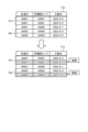
- FIG. 3 is a diagram for explaining the procedure for deleting duplicates according to an embodiment.
- FIG. 3 shows the contents of each table in a state in which they can be read as natural language, but in reality, the process shown in FIG. 3 is performed using secret computation on tables that have been accumulated in an unreadable share state (for example, a list of numbers that appear meaningless).
- Table 51 in FIG. 3 is the table that is subject to duplicate deletion.
- records with duplicates in the "Employee ID" column and the "Department Code” column are deleted except for one. Therefore, record group 61 and record group 62 in table 51 in FIG. 3 are subject to duplicate deletion.
- the determination unit 1351 determines the duplicate deletion key, the sort key, and the sort order.
- the duplicate deletion key and the sort key are a set of one or more columns.
- the sort key is used in the sorting process described below.
- the determination unit 1351 can determine a duplicate deletion key and a sort key in response to a request from a user received via the terminal device 40. However, the duplicate deletion key and the sort key are assumed to be different.
- the determination unit 1351 receives a request to "delete records with duplicate 'employee ID' and 'department code', leaving only the record with the oldest 'entry date'.” In this case, the determination unit 1351 determines the "employee ID” column and the "department code” column as duplicate deletion keys. The determination unit 1351 also determines the "entry date” column as the sort key. The determination unit 1351 also determines the sort order to be ascending.
- the determination unit 1351 determines the sort order to be ascending. Conversely, if the record requested to be kept is the record with the largest value (which is equivalent to the newest in the case of date and time), the determination unit 1351 determines the sort order to be descending.
- the sorting unit 1352 sorts the records of table 51, including records with duplicate values for the duplicate deletion key, by secret calculation using the sort key.
- the sorting unit 1352 also sorts the records of the table in a specified order, either ascending or descending.
- Table 52 is the table after the sorting unit 1352 sorts table 51.
- the determination unit 1351 has determined that the "Entry Date” column is the sort key, and that the sort order is ascending. Therefore, the sort unit 1352 sorts the records in table 51 in ascending order of the "Entry Date” column. In this case, as shown in table 52, records with smaller values in the "Entry Date” column (older dates and times) are placed higher.
- the deletion unit 1353 uses secret computation to delete all records except for one record located at a predetermined position in each set of records with duplicate deletion keys included in the table 52 sorted by the sort unit 1352. For example, in the example of FIG. 3, the deletion unit 1353 deletes all records except for the one record located at the top of the set.
- Record group 61 and record group 62 in table 52 are both collections of records with duplicate deletion keys.
- the deletion unit 1353 deletes the record at the bottom of the records included in record group 61 (the record whose "Entry Date” column has a value of "9/3/2022") and leaves the other records (the records whose "Entry Date” column has a value of "9/2/2022").
- the deletion unit 1353 may delete the records so that the lowest record remains, rather than the topmost record.
- the determination unit 1351 determines the order opposite to that described above. That is, if the record requested to be kept is the record with the smallest value (which in the case of date and time is equivalent to the oldest), the determination unit 1351 determines the sort order to be descending. Conversely, if the record requested to be kept is the record with the largest value (which in the case of date and time is equivalent to the newest), the determination unit 1351 determines the sort order to be ascending.
- the output control unit 1354 outputs table 52 after deleting the records.
- the output control unit 1354 may also output the results of further statistical analysis using table 52 from which the records have been deleted.
- FIG. 4 is a flowchart showing the flow of processing by the analysis device according to the embodiment.
- the analysis device 13 determines a duplicate deletion key, a sort key, and a sort order based on a request from a user (step S101).
- the analysis device 13 sorts the records in the table using secret computation based on the determined duplicate deletion key and order (step S102).
- the analysis device 13 obtains a group of records with duplicate deletion keys from the sorted table (step S103). Then, the analysis device 13 selects one of the unprocessed record groups (step S104).
- the analysis device 13 deletes all records except the top record from the selected record group using secret calculation (step S105).
- step S106 If there are unselected record groups (step S106, Yes), the analysis device 13 returns to step S104 and repeats the process. If there are no unselected record groups (step S106, No), the analysis device 13 outputs the final table (step S107).
- the analysis device 13 includes a sorting unit 1352 and a deleting unit 1353.
- the sorting unit 1352 sorts records of a table including records with duplicate values of a first key (duplicate deletion key) by a second key (sort key) different from the first key, by secure computation.
- the deleting unit 1353 deletes, by secure computation, records other than one record located at a predetermined position in each set of records with duplicate first keys included in the table sorted by the sorting unit 1352. This allows the analysis device 13 to specify records to be kept by sorting such that the records to be kept when deleting duplicates are located at a predetermined position.
- the sorting unit 1352 sorts the records in the table in a specified order, either ascending or descending.
- the deletion unit 1353 deletes all records in the set except for one record that is at the top or bottom. This allows the analysis device 13 to place the records that are not to be deleted at the top or bottom in response to a user request, and delete the other records.
- each component of each device shown in the figure is functionally conceptual, and does not necessarily have to be physically configured as shown in the figure.
- the specific form of distribution and integration of each device is not limited to that shown in the figure, and all or a part of it can be functionally or physically distributed or integrated in any unit depending on various loads, usage conditions, etc.
- each processing function performed by each device can be realized in whole or in part by a CPU (Central Processing Unit) and a program analyzed and executed by the CPU, or can be realized as hardware by wired logic. Note that the program may be executed not only by the CPU but also by other processors such as a GPU.
- the analysis device 13 can be implemented by installing an analysis program that executes the above-mentioned analysis processing as package software or online software on a desired computer.
- the above-mentioned analysis program can be executed by an information processing device, thereby making the information processing device function as the analysis device 13.
- the information processing device referred to here includes desktop or notebook personal computers.
- the information processing device also includes mobile communication terminals such as smartphones, mobile phones, and PHS (Personal Handyphone Systems), as well as slate terminals such as PDAs (Personal Digital Assistants).
- the analysis device 13 can also be implemented as an analysis server device that treats a terminal device used by a user as a client and provides services related to the above-mentioned analysis processing to the client.
- the analysis server device is implemented as a server device that provides an analysis service that receives a table to be deleted for duplicates as input and outputs a table after duplicates have been deleted.
- FIG. 5 is a diagram showing an example of a computer that executes an analysis program.
- the computer 1000 has, for example, a memory 1010 and a CPU 1020.
- the computer 1000 also has a hard disk drive interface 1030, a disk drive interface 1040, a serial port interface 1050, a video adapter 1060, and a network interface 1070. Each of these components is connected by a bus 1080.
- the memory 1010 includes a ROM (Read Only Memory) 1011 and a RAM (Random Access Memory) 1012.
- the ROM 1011 stores a boot program such as a BIOS (Basic Input Output System).
- BIOS Basic Input Output System
- the hard disk drive interface 1030 is connected to a hard disk drive 1090.
- the disk drive interface 1040 is connected to a disk drive 1100.
- a removable storage medium such as a magnetic disk or optical disk is inserted into the disk drive 1100.
- the serial port interface 1050 is connected to a mouse 1110 and a keyboard 1120, for example.
- the video adapter 1060 is connected to a display 1130, for example.
- the hard disk drive 1090 stores, for example, an OS 1091, an application program 1092, a program module 1093, and program data 1094. That is, the programs that define each process of the analysis device 13 are implemented as program modules 1093 in which computer-executable code is written.
- the program modules 1093 are stored, for example, in the hard disk drive 1090.
- a program module 1093 for executing processes similar to the functional configuration of the analysis device 13 is stored in the hard disk drive 1090.
- the hard disk drive 1090 may be replaced by an SSD (Solid State Drive).
- the setting data used in the processing of the above-mentioned embodiment is stored as program data 1094, for example, in memory 1010 or hard disk drive 1090.
- the CPU 1020 reads out the program module 1093 or program data 1094 stored in memory 1010 or hard disk drive 1090 into RAM 1012 as necessary, and executes the processing of the above-mentioned embodiment.
- the program module 1093 and program data 1094 may not necessarily be stored in the hard disk drive 1090, but may be stored in a removable storage medium, for example, and read by the CPU 1020 via the disk drive 1100 or the like.
- the program module 1093 and program data 1094 may be stored in another computer connected via a network (such as a LAN (Local Area Network), WAN (Wide Area Network)).
- the program module 1093 and program data 1094 may then be read by the CPU 1020 from the other computer via the network interface 1070.
Landscapes
- Engineering & Computer Science (AREA)
- Theoretical Computer Science (AREA)
- Databases & Information Systems (AREA)
- General Physics & Mathematics (AREA)
- Physics & Mathematics (AREA)
- General Engineering & Computer Science (AREA)
- Data Mining & Analysis (AREA)
- General Health & Medical Sciences (AREA)
- Health & Medical Sciences (AREA)
- Bioethics (AREA)
- Computer Security & Cryptography (AREA)
- Computer Hardware Design (AREA)
- Software Systems (AREA)
- Quality & Reliability (AREA)
- Computational Linguistics (AREA)
- Medical Informatics (AREA)
- Information Retrieval, Db Structures And Fs Structures Therefor (AREA)
- Storage Device Security (AREA)
Abstract
Description
これまで説明してきたように、分析装置13は、ソート部1352及び削除部1353を有する。ソート部1352は、第1のキー(重複削除キー)の値が重複するレコードを含むテーブルのレコードを、第1のキーと異なる第2のキー(ソートキー)で秘密計算によりソートする。削除部1353は、ソート部1352によるソートが行われたテーブルに含まれる、第1のキーが重複するレコードの集合のそれぞれについて、集合の中であらかじめ定められた位置にある1つのレコード以外のレコードを秘密計算により削除する。これにより、分析装置13は、重複削除の際に残すレコードがあらかじめ定められた位置に配置されるようにソートを行うことで、残すレコードを指定できる。
また、図示した各装置の各構成要素は機能概念的なものであり、必ずしも物理的に図示のように構成されていることを要しない。すなわち、各装置の分散及び統合の具体的形態は図示のものに限られず、その全部又は一部を、各種の負荷や使用状況等に応じて、任意の単位で機能的又は物理的に分散又は統合して構成することができる。さらに、各装置にて行われる各処理機能は、その全部又は任意の一部が、CPU(Central Processing Unit)及び当該CPUにて解析実行されるプログラムにて実現され、あるいは、ワイヤードロジックによるハードウェアとして実現され得る。なお、プログラムは、CPUだけでなく、GPU等の他のプロセッサによって実行されてもよい。
一実施形態として、分析装置13は、パッケージソフトウェアやオンラインソフトウェアとして上記の分析処理を実行する分析プログラムを所望のコンピュータにインストールさせることによって実装できる。例えば、上記の分析プログラムを情報処理装置に実行させることにより、情報処理装置を分析装置13として機能させることができる。ここで言う情報処理装置には、デスクトップ型又はノート型のパーソナルコンピュータが含まれる。また、その他にも、情報処理装置にはスマートフォン、携帯電話機やPHS(Personal Handyphone System)等の移動体通信端末、さらには、PDA(Personal Digital Assistant)等のスレート端末等がその範疇に含まれる。
10 秘密計算システム
11 データ蓄積部
12 データ処理部
13 分析装置
131 通信部
132 入力部
133 出力部
134 記憶部
135 制御部
1351 決定部
1352 ソート部
1353 削除部
Claims (5)
- 第1のキーの値が重複するレコードを含むテーブルのレコードを、前記第1のキーと異なる第2のキーで秘密計算によりソートするソート部と、
前記ソート部によるソートが行われた前記テーブルに含まれる、前記第1のキーが重複するレコードの集合のそれぞれについて、前記集合の中であらかじめ定められた位置にある1つのレコード以外のレコードを、秘密計算により削除する削除部と、
を有することを特徴とする分析装置。 - 前記ソート部は、昇順及び降順のうち、指定された順序で前記テーブルのレコードをソートすることを特徴とする請求項1に記載の分析装置。
- 前記削除部は、前記集合の中で最上位又は最下位にある1つのレコード以外のレコードを削除する
ことを特徴とする請求項1又は2に記載の分析装置。 - 分析装置によって実行される分析方法であって、
第1のキーの値が重複するレコードを含むテーブルのレコードを、前記第1のキーと異なる第2のキーで秘密計算によりソートするソート工程と、
前記ソート工程によるソートが行われた前記テーブルに含まれる、前記第1のキーが重複するレコードの集合のそれぞれについて、前記集合の中であらかじめ定められた位置にある1つのレコード以外のレコードを、秘密計算により削除する削除工程と、
を含むことを特徴とする分析方法。 - 第1のキーの値が重複するレコードを含むテーブルのレコードを、前記第1のキーと異なる第2のキーで秘密計算によりソートするソートステップと、
前記ソートステップによるソートが行われた前記テーブルに含まれる、前記第1のキーが重複するレコードの集合のそれぞれについて、前記集合の中であらかじめ定められた位置にある1つのレコード以外のレコードを、秘密計算により削除する削除ステップと、
をコンピュータに実行させることを特徴とする分析プログラム。
Priority Applications (3)
| Application Number | Priority Date | Filing Date | Title |
|---|---|---|---|
| AU2024266332A AU2024266332A1 (en) | 2023-05-01 | 2024-03-04 | Analysis device, analysis method, and analysis program |
| EP24800025.9A EP4708260A4 (en) | 2023-05-01 | 2024-03-04 | Analysis device, analysis method, and analysis program |
| US19/375,290 US20260056925A1 (en) | 2023-05-01 | 2025-10-31 | Analysis device, analysis method, and analysis program |
Applications Claiming Priority (2)
| Application Number | Priority Date | Filing Date | Title |
|---|---|---|---|
| JP2023075832A JP2024160620A (ja) | 2023-05-01 | 2023-05-01 | 分析装置、分析方法及び分析プログラム |
| JP2023-075832 | 2023-05-01 |
Related Child Applications (1)
| Application Number | Title | Priority Date | Filing Date |
|---|---|---|---|
| US19/375,290 Continuation US20260056925A1 (en) | 2023-05-01 | 2025-10-31 | Analysis device, analysis method, and analysis program |
Publications (1)
| Publication Number | Publication Date |
|---|---|
| WO2024228294A1 true WO2024228294A1 (ja) | 2024-11-07 |
Family
ID=93332911
Family Applications (1)
| Application Number | Title | Priority Date | Filing Date |
|---|---|---|---|
| PCT/JP2024/007990 Ceased WO2024228294A1 (ja) | 2023-05-01 | 2024-03-04 | 分析装置、分析方法及び分析プログラム |
Country Status (5)
| Country | Link |
|---|---|
| US (1) | US20260056925A1 (ja) |
| EP (1) | EP4708260A4 (ja) |
| JP (1) | JP2024160620A (ja) |
| AU (1) | AU2024266332A1 (ja) |
| WO (1) | WO2024228294A1 (ja) |
Citations (6)
| Publication number | Priority date | Publication date | Assignee | Title |
|---|---|---|---|---|
| JP2014139640A (ja) | 2013-01-21 | 2014-07-31 | Nippon Telegr & Teleph Corp <Ntt> | 秘密計算による表の等結合システム、方法 |
| WO2019124260A1 (ja) | 2017-12-18 | 2019-06-27 | 日本電信電話株式会社 | 秘密計算システム及び方法 |
| WO2019225401A1 (ja) * | 2018-05-25 | 2019-11-28 | 日本電信電話株式会社 | 秘密集約関数計算システム、秘密計算装置、秘密集約関数計算方法、およびプログラム |
| JP2020042128A (ja) | 2018-09-10 | 2020-03-19 | 日本電信電話株式会社 | 秘密統計処理システム、方法、統計処理装置及びプログラム |
| WO2021144840A1 (ja) * | 2020-01-14 | 2021-07-22 | 日本電信電話株式会社 | 暗号化データ分析装置、暗号化データ分析方法、プログラム |
| WO2022254691A1 (ja) * | 2021-06-04 | 2022-12-08 | 日本電信電話株式会社 | 秘密計算装置、秘密計算システム、秘密計算方法、およびプログラム |
-
2023
- 2023-05-01 JP JP2023075832A patent/JP2024160620A/ja active Pending
-
2024
- 2024-03-04 EP EP24800025.9A patent/EP4708260A4/en active Pending
- 2024-03-04 AU AU2024266332A patent/AU2024266332A1/en active Pending
- 2024-03-04 WO PCT/JP2024/007990 patent/WO2024228294A1/ja not_active Ceased
-
2025
- 2025-10-31 US US19/375,290 patent/US20260056925A1/en active Pending
Patent Citations (6)
| Publication number | Priority date | Publication date | Assignee | Title |
|---|---|---|---|---|
| JP2014139640A (ja) | 2013-01-21 | 2014-07-31 | Nippon Telegr & Teleph Corp <Ntt> | 秘密計算による表の等結合システム、方法 |
| WO2019124260A1 (ja) | 2017-12-18 | 2019-06-27 | 日本電信電話株式会社 | 秘密計算システム及び方法 |
| WO2019225401A1 (ja) * | 2018-05-25 | 2019-11-28 | 日本電信電話株式会社 | 秘密集約関数計算システム、秘密計算装置、秘密集約関数計算方法、およびプログラム |
| JP2020042128A (ja) | 2018-09-10 | 2020-03-19 | 日本電信電話株式会社 | 秘密統計処理システム、方法、統計処理装置及びプログラム |
| WO2021144840A1 (ja) * | 2020-01-14 | 2021-07-22 | 日本電信電話株式会社 | 暗号化データ分析装置、暗号化データ分析方法、プログラム |
| WO2022254691A1 (ja) * | 2021-06-04 | 2022-12-08 | 日本電信電話株式会社 | 秘密計算装置、秘密計算システム、秘密計算方法、およびプログラム |
Non-Patent Citations (2)
| Title |
|---|
| NTT CORP., SYSTEM OF SECURE COMPUTATION AND PRINCIPLES THEREOF, 24 November 2022 (2022-11-24), Retrieved from the Internet <URL:https://www.rd.ntt/sil/project/sc/securecomputation.html> |
| See also references of EP4708260A1 |
Also Published As
| Publication number | Publication date |
|---|---|
| JP2024160620A (ja) | 2024-11-14 |
| US20260056925A1 (en) | 2026-02-26 |
| EP4708260A4 (en) | 2026-05-06 |
| EP4708260A1 (en) | 2026-03-11 |
| AU2024266332A1 (en) | 2025-11-20 |
Similar Documents
| Publication | Publication Date | Title |
|---|---|---|
| US12614113B2 (en) | Using consistency metadata for filtering of machine learning data across jobs | |
| US12056583B2 (en) | Target variable distribution-based acceptance of machine learning test data sets | |
| US10585913B2 (en) | Apparatus and method for distributed query processing utilizing dynamically generated in-memory term maps | |
| US10713589B1 (en) | Consistent sort-based record-level shuffling of machine learning data | |
| US10366053B1 (en) | Consistent randomized record-level splitting of machine learning data | |
| US10168921B1 (en) | Systems and methods for storing time-series data | |
| US10360405B2 (en) | Anonymization apparatus, and program | |
| CN103620601A (zh) | 在映射缩减过程中汇合表 | |
| JP2017049693A (ja) | 個人情報匿名化方法、プログラム、及び情報処理装置 | |
| US9619458B2 (en) | System and method for phrase matching with arbitrary text | |
| KR20130126012A (ko) | 비즈니스 인텔리전스의리포트 제공 방법 및 장치 | |
| WO2024228294A1 (ja) | 分析装置、分析方法及び分析プログラム | |
| US10282361B2 (en) | Transforming time series data points from concurrent processes | |
| US20240143674A1 (en) | Processing and publishing scanned data for detecting entities in a set of domains via a parallel pipeline | |
| WO2024228293A1 (ja) | 分析装置、分析方法及び分析プログラム | |
| CN114168557B (zh) | 一种访问日志的处理方法、装置、计算机设备和存储介质 | |
| WO2024228299A1 (ja) | 分析装置、分析方法及び分析プログラム | |
| EP4217880B1 (en) | Deterministic mapping and routing of items to physical resources | |
| JP7720512B2 (ja) | 情報提供装置、情報提供方法及び情報提供プログラム | |
| WO2024228296A1 (ja) | 分析装置、分析方法及び分析プログラム | |
| Eom et al. | Android malware detection using feature selections and random forest | |
| US11734245B1 (en) | Systems and methods for storing time-series data | |
| WO2024228295A1 (ja) | 分析装置、分析方法及び分析プログラム | |
| CN109871215B (zh) | 软件发布的方法和装置 | |
| WO2024228297A1 (ja) | 分析装置、分析方法及び分析プログラム |
Legal Events
| Date | Code | Title | Description |
|---|---|---|---|
| 121 | Ep: the epo has been informed by wipo that ep was designated in this application |
Ref document number: 24800025 Country of ref document: EP Kind code of ref document: A1 |
|
| WWE | Wipo information: entry into national phase |
Ref document number: AU2024266332 Country of ref document: AU |
|
| ENP | Entry into the national phase |
Ref document number: 2024266332 Country of ref document: AU Date of ref document: 20240304 Kind code of ref document: A |
|
| ENP | Entry into the national phase |
Ref document number: 2024800025 Country of ref document: EP Effective date: 20251201 |
|
| WWE | Wipo information: entry into national phase |
Ref document number: 2024800025 Country of ref document: EP |
|
| NENP | Non-entry into the national phase |
Ref country code: DE |
|
| ENP | Entry into the national phase |
Ref document number: 2024800025 Country of ref document: EP Effective date: 20251201 |
|
| ENP | Entry into the national phase |
Ref document number: 2024800025 Country of ref document: EP Effective date: 20251201 |
|
| ENP | Entry into the national phase |
Ref document number: 2024800025 Country of ref document: EP Effective date: 20251201 |
|
| ENP | Entry into the national phase |
Ref document number: 2024800025 Country of ref document: EP Effective date: 20251201 |
|
| ENP | Entry into the national phase |
Ref document number: 2024800025 Country of ref document: EP Effective date: 20251201 |
|
| ENP | Entry into the national phase |
Ref document number: 2024800025 Country of ref document: EP Effective date: 20251201 |
|
| ENP | Entry into the national phase |
Ref document number: 2024800025 Country of ref document: EP Effective date: 20251201 |
|
| ENP | Entry into the national phase |
Ref document number: 2024800025 Country of ref document: EP Effective date: 20251201 |
|
| ENP | Entry into the national phase |
Ref document number: 2024800025 Country of ref document: EP Effective date: 20251201 |
|
| WWP | Wipo information: published in national office |
Ref document number: 2024800025 Country of ref document: EP |