WO2025004150A1 - 電動車両 - Google Patents
電動車両 Download PDFInfo
- Publication number
- WO2025004150A1 WO2025004150A1 PCT/JP2023/023632 JP2023023632W WO2025004150A1 WO 2025004150 A1 WO2025004150 A1 WO 2025004150A1 JP 2023023632 W JP2023023632 W JP 2023023632W WO 2025004150 A1 WO2025004150 A1 WO 2025004150A1
- Authority
- WO
- WIPO (PCT)
- Prior art keywords
- electric
- electric vehicle
- vehicle
- case
- side member
- Prior art date
- Legal status (The legal status is an assumption and is not a legal conclusion. Google has not performed a legal analysis and makes no representation as to the accuracy of the status listed.)
- Ceased
Links
Images





Classifications
-
- B—PERFORMING OPERATIONS; TRANSPORTING
- B60—VEHICLES IN GENERAL
- B60K—ARRANGEMENT OR MOUNTING OF PROPULSION UNITS OR OF TRANSMISSIONS IN VEHICLES; ARRANGEMENT OR MOUNTING OF PLURAL DIVERSE PRIME-MOVERS IN VEHICLES; AUXILIARY DRIVES FOR VEHICLES; INSTRUMENTATION OR DASHBOARDS FOR VEHICLES; ARRANGEMENTS IN CONNECTION WITH COOLING, AIR INTAKE, GAS EXHAUST OR FUEL SUPPLY OF PROPULSION UNITS IN VEHICLES
- B60K1/00—Arrangement or mounting of electrical propulsion units
-
- B—PERFORMING OPERATIONS; TRANSPORTING
- B60—VEHICLES IN GENERAL
- B60K—ARRANGEMENT OR MOUNTING OF PROPULSION UNITS OR OF TRANSMISSIONS IN VEHICLES; ARRANGEMENT OR MOUNTING OF PLURAL DIVERSE PRIME-MOVERS IN VEHICLES; AUXILIARY DRIVES FOR VEHICLES; INSTRUMENTATION OR DASHBOARDS FOR VEHICLES; ARRANGEMENTS IN CONNECTION WITH COOLING, AIR INTAKE, GAS EXHAUST OR FUEL SUPPLY OF PROPULSION UNITS IN VEHICLES
- B60K5/00—Arrangement or mounting of internal-combustion or jet-propulsion units
- B60K5/12—Arrangement of engine supports
-
- B—PERFORMING OPERATIONS; TRANSPORTING
- B60—VEHICLES IN GENERAL
- B60K—ARRANGEMENT OR MOUNTING OF PROPULSION UNITS OR OF TRANSMISSIONS IN VEHICLES; ARRANGEMENT OR MOUNTING OF PLURAL DIVERSE PRIME-MOVERS IN VEHICLES; AUXILIARY DRIVES FOR VEHICLES; INSTRUMENTATION OR DASHBOARDS FOR VEHICLES; ARRANGEMENTS IN CONNECTION WITH COOLING, AIR INTAKE, GAS EXHAUST OR FUEL SUPPLY OF PROPULSION UNITS IN VEHICLES
- B60K5/00—Arrangement or mounting of internal-combustion or jet-propulsion units
- B60K5/12—Arrangement of engine supports
- B60K5/1208—Resilient supports
-
- B—PERFORMING OPERATIONS; TRANSPORTING
- B60—VEHICLES IN GENERAL
- B60K—ARRANGEMENT OR MOUNTING OF PROPULSION UNITS OR OF TRANSMISSIONS IN VEHICLES; ARRANGEMENT OR MOUNTING OF PLURAL DIVERSE PRIME-MOVERS IN VEHICLES; AUXILIARY DRIVES FOR VEHICLES; INSTRUMENTATION OR DASHBOARDS FOR VEHICLES; ARRANGEMENTS IN CONNECTION WITH COOLING, AIR INTAKE, GAS EXHAUST OR FUEL SUPPLY OF PROPULSION UNITS IN VEHICLES
- B60K5/00—Arrangement or mounting of internal-combustion or jet-propulsion units
- B60K5/12—Arrangement of engine supports
- B60K5/1208—Resilient supports
- B60K5/1216—Resilient supports characterised by the location of the supports relative to the motor or to each other
-
- B—PERFORMING OPERATIONS; TRANSPORTING
- B60—VEHICLES IN GENERAL
- B60K—ARRANGEMENT OR MOUNTING OF PROPULSION UNITS OR OF TRANSMISSIONS IN VEHICLES; ARRANGEMENT OR MOUNTING OF PLURAL DIVERSE PRIME-MOVERS IN VEHICLES; AUXILIARY DRIVES FOR VEHICLES; INSTRUMENTATION OR DASHBOARDS FOR VEHICLES; ARRANGEMENTS IN CONNECTION WITH COOLING, AIR INTAKE, GAS EXHAUST OR FUEL SUPPLY OF PROPULSION UNITS IN VEHICLES
- B60K5/00—Arrangement or mounting of internal-combustion or jet-propulsion units
- B60K5/12—Arrangement of engine supports
- B60K5/1241—Link-type support
-
- B—PERFORMING OPERATIONS; TRANSPORTING
- B60—VEHICLES IN GENERAL
- B60K—ARRANGEMENT OR MOUNTING OF PROPULSION UNITS OR OF TRANSMISSIONS IN VEHICLES; ARRANGEMENT OR MOUNTING OF PLURAL DIVERSE PRIME-MOVERS IN VEHICLES; AUXILIARY DRIVES FOR VEHICLES; INSTRUMENTATION OR DASHBOARDS FOR VEHICLES; ARRANGEMENTS IN CONNECTION WITH COOLING, AIR INTAKE, GAS EXHAUST OR FUEL SUPPLY OF PROPULSION UNITS IN VEHICLES
- B60K5/00—Arrangement or mounting of internal-combustion or jet-propulsion units
- B60K5/12—Arrangement of engine supports
- B60K5/1275—Plastically deformable supports
-
- B—PERFORMING OPERATIONS; TRANSPORTING
- B60—VEHICLES IN GENERAL
- B60Y—INDEXING SCHEME RELATING TO ASPECTS CROSS-CUTTING VEHICLE TECHNOLOGY
- B60Y2200/00—Type of vehicle
- B60Y2200/90—Vehicles comprising electric prime movers
- B60Y2200/91—Electric vehicles
-
- B—PERFORMING OPERATIONS; TRANSPORTING
- B60—VEHICLES IN GENERAL
- B60Y—INDEXING SCHEME RELATING TO ASPECTS CROSS-CUTTING VEHICLE TECHNOLOGY
- B60Y2306/00—Other features of vehicle sub-units
- B60Y2306/01—Reducing damages in case of crash, e.g. by improving battery protection
-
- B—PERFORMING OPERATIONS; TRANSPORTING
- B60—VEHICLES IN GENERAL
- B60Y—INDEXING SCHEME RELATING TO ASPECTS CROSS-CUTTING VEHICLE TECHNOLOGY
- B60Y2400/00—Special features of vehicle units
- B60Y2400/60—Electric Machines, e.g. motors or generators
-
- B—PERFORMING OPERATIONS; TRANSPORTING
- B60—VEHICLES IN GENERAL
- B60Y—INDEXING SCHEME RELATING TO ASPECTS CROSS-CUTTING VEHICLE TECHNOLOGY
- B60Y2410/00—Constructional features of vehicle sub-units
- B60Y2410/10—Housings
Definitions
- the present invention relates to an electric vehicle.
- Electric vehicles are equipped with electric units that include components with built-in high-voltage circuits, and aluminum housings are typically used for the electric unit cases.
- aluminum housings are not very strong, there is a risk that the electric unit case will break in the event of a vehicle collision, etc. If the electric unit case breaks, it may lead to abnormal firing (TI) or electric shock (ES).
- TI abnormal firing
- ES electric shock
- a protector may be attached to the case of the electric unit to increase the strength of the case, but if the space is limited, it may not be possible to install the protector.
- JP2018-16247A discloses an electric vehicle in which the motor case is provided with a protrusion that protrudes forward of the vehicle.
- the protrusion provided on the motor case prevents damage to the motor case in the event of a vehicle collision.
- the present invention has been made in consideration of the above problems, and aims to provide an electric vehicle that can prevent damage or breakage of the electric unit case in the event of a vehicle collision.
- an electric vehicle in which an electric unit including an electric motor and a case housing the electric motor is mounted and fixed to the vehicle body at a plurality of fixing points.
- the fixing points include at least a first fixing point set on a side member located on the lateral side of the electric vehicle relative to the electric unit, and a second fixing point set on a suspension member located on the rear side of the electric vehicle relative to the electric unit.
- the case has a reinforcing portion that enhances rigidity at a portion of the case that is located on the rear side of the electric vehicle relative to a straight line connecting the first fixing point and the second fixing point, when viewed from above the electric vehicle.
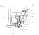
- FIG. 1 is a schematic diagram showing the main configuration of an electric unit mounted on an electric vehicle according to an embodiment of the present invention.
- FIG. 2 is a schematic diagram of the electric powertrain.
- FIG. 3 is a diagram for explaining the installation position of the reinforcing portion.
- FIG. 4 is a top view of the first mount fixing part.
- FIG. 5 is a top view of the second mount fixing portion.
- FIG. 6 is a diagram showing the positional relationship between the side member and the reinforcing portion.
- FIG. 7 is a view showing the inside of the rear cover.
- FIG. 8 is a partial enlarged view of the electric unit before the rear cover is fastened.
- FIG. 9 is a partial enlarged view of the electric unit.
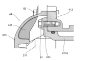
- FIG. 10 is a cross-sectional view of the periphery of a fastening portion between the inner housing and the outer housing.
- FIG. 1 is a schematic diagram showing the main configuration of an electric unit 10 mounted on an electric vehicle (hereinafter also referred to as a vehicle) 100 according to an embodiment of the present invention, as viewed from above the vehicle 100.
- the electric vehicle 100 is a so-called series hybrid vehicle that includes a generator (power generating motor) 22 that is driven by an engine (not shown) to generate electricity, and an electric motor (driving motor) 21 that is driven by electric power from a battery (not shown) to run the electric vehicle 100.
- the present invention is not limited to this, and may be another hybrid vehicle, or may be, for example, an electric vehicle that does not have an engine and a generator (power generating motor).
- the electric unit 10 includes an electric power train (hereinafter referred to as ePT) 2, a gearbox 3, and a case 4 that houses the ePT 2 and the gearbox 3.
- the electric unit 10 is fixed to the body of the vehicle 100 via a first mount fixing portion 11 and a second mount fixing portion 12.
- FIG. 2 is a schematic diagram of the ePT2, and is a cross-sectional view of the ePT2 as seen from the vehicle width direction of the electric vehicle 100.
- the ePT2 includes an electric motor (electric motor, drive motor) 21, a generator 22, and an inverter (power conversion device) 23 arranged on top of the electric motor 21 and the generator 22.
- the ePT2 receives power from a battery (not shown) to drive the electric motor 21, thereby propelling the electric vehicle 100.
- the electric motor 21 is an electric motor (drive motor) that receives power from a battery (not shown) and rotates the drive wheels via the axles of the electric vehicle 100, and is, for example, a three-phase motor. Furthermore, when the electric vehicle 100 decelerates, the electric motor 21 rotates together with the drive wheels and generates regenerative power. In other words, the electric motor 21 is a rotating electric machine that also functions as a generator.
- the generator 22 is a generator motor that generates electricity when driven by an engine (not shown), and is, for example, a three-phase motor.
- the electric motor 21 and the generator 22 are housed in a motor housing 41 that constitutes part of the case 4 described below.
- the inverter 23 includes electrical components 231 such as a power module and a capacitor, and has a built-in high-voltage circuit.
- the inverter 23 is housed in a lid-shaped inverter housing 42 that constitutes part of the case 4 described below, and is arranged on the motor housing 41 in a state where it is inclined downward toward the front of the electric vehicle 100.
- the electrical components 231 of the inverter 23 are arranged on the inner surface of the inverter housing 42.
- the inverter 23 is electrically connected to the electric motor 21 and the generator 22, and converts the DC power output by the battery into AC power and supplies it to the electric motor 21 to drive the electric motor 21.
- the inverter 23 also converts the regenerated power of the electric motor (rotating electric machine) 21 and the generated power of the generator 22 from AC power to DC power and supplies it to the battery to charge the battery.
- the gearbox 3 ( Figure 1) is a gear device having a gear train made up of multiple gears, including a gear train that connects the drive wheels of the electric vehicle 100 to the electric motor (electric motor, drive motor) 21, and a gear train that connects the engine to the generator 22. These gear trains are housed in a gearbox housing 43 that constitutes part of the case 4.
- Case 4 is made of aluminum or the like, and houses ePT 2 and gearbox 3.
- Case 4 is constructed by integrating a motor housing 41 that houses the electric motor 21 and generator 22, an inverter housing 42 that houses the inverter 23, and a gearbox housing 43 that houses the gear train of the gearbox 3.
- An engine (not shown) that is connected to the gearbox 3 is installed on the right side of the vehicle 100 relative to the electric unit 10, and case 4 is integrated with the engine.
- the motor housing 41 is composed of an inner housing 411 that houses the electric motor 21 and the generator 22, an outer housing 412 that houses the inner housing 411 inside, and a rear cover 413 (see FIG. 9) that covers the opening 4111 of the inner housing 411.
- the inner housing 411 includes a cylindrical first inner housing 411A that houses the electric motor 21, and a cylindrical second inner housing 411B that houses the generator 22.
- the outer housing 412 has two parallel cylindrical housing sections, and houses the first inner housing 411A and the second inner housing 411B in each housing section.
- the rear cover 413 is configured to cover the opening 4111 of the cylindrical inner housing 411 (411A, 411B), and is fastened to the outer housing 412 by bolts or the like on the outside of the periphery of the inner housing 411 (411A, 411B).
- the motor housing 41 is composed of one cylindrical inner housing 411, an outer housing 412 having one cylindrical storage section, and a rear cover 413 that covers the opening 4111 of the inner housing 411.
- the inverter housing 42 is configured like a lid that opens downwards, and is placed on the motor housing 41.
- the electrical components 231 of the inverter 23 are arranged on the inner surface of the inverter housing 42.
- the tip of the outer edge of the inverter housing 42 is formed into a flange shape, and is fastened to the motor housing 41 by bolts or the like.
- the gearbox housing 43 is cylindrical and houses the gear train of the gearbox 3 inside.
- the gearbox housing 43 is connected to the motor housing 41.
- the tip of the outer edge of the gearbox housing 43 is formed into a flange shape and is fastened to the motor housing 41 by bolts or the like.
- the first mount fixing part 11 is interposed between the electric motor 21 of the ePT2 and the side member 50, and is composed of a mount member having one end fastened to the case 4 of the electric unit 10 by a bolt or the like and the other end fastened to the side member 50 by a bolt or the like.
- the side member 50 is composed of a steel plate or the like and is located on the left side of the vehicle 100 relative to the electric unit 10 (hereinafter also simply referred to as the left side).
- the first mount fixing part 11 mounts the electric unit 10 to the side member 50 located on the left side of the vehicle 100 relative to the electric unit 10.
- the second mount fixing part 12 is interposed between the gearbox 3 and the suspension member 60, and is composed of a mount member having one end fastened to the case 4 of the electric unit 10 by a bolt or the like and the other end fastened to the suspension member 60 by a bolt or the like.
- the suspension member 60 is composed of a steel plate or the like and is configured to surround the electric unit 10 from four directions, front, rear, left and right, when viewed from above the vehicle 100.
- the electric unit 10 is mounted and fixed to a rear portion of the suspension member 60 by the second mount fixing part 12 on the rear side of the vehicle 100 relative to the electric unit 10 (hereinafter also simply referred to as the rear side).
- the suspension member 60 is not limited to the above configuration as long as it has at least a portion located on the rear side of the vehicle 100 relative to the electric unit 10.
- the electric unit 10 of the electric vehicle 100 is mounted to the side member 50 located on the left side of the vehicle 100 relative to the electric unit 10, and to the suspension member 60 located on the rear side of the vehicle 100 relative to the electric unit 10.
- an engine (not shown) is installed on the right side of the vehicle 100 relative to the electric unit 10, and the engine is mounted and fixed to a side member (not shown) located on the opposite side of the side member 50 (i.e., on the right side of the vehicle 100 relative to the electric unit 10).
- an aluminum housing is used for the case of the electric unit, as in case 4 of this embodiment.
- damage, etc. the case of the electric unit will be damaged or broken (hereinafter referred to as damage, etc.) during a vehicle collision, etc. If the case of the electric unit is damaged, etc., it may lead to abnormal ignition (TI) or electric shock (ES).
- TI abnormal ignition
- ES electric shock
- a protector may be attached to the case of the electric unit to increase the strength of the case, but if the space is narrow, it may not be possible to install the protector. In other words, it is difficult to install a protector, etc. in areas where a vehicle body crush stroke is required or where clearance is required. For this reason, there is a risk that damage, etc. to the case of the electric unit may not be sufficiently prevented.
- a reinforcement part 44 (see FIG. 3) with enhanced rigidity is provided in a part of the case 4 located rearward of the vehicle 100 (hereinafter also referred to as the rearward side of the straight line) from the straight line L-L connecting the fixed point (hereinafter referred to as the first fixed point) where the electric unit 10 is mounted (fastened) to the side member 50 on the left side and the fixed point (hereinafter referred to as the second fixed point) where the electric unit 10 is mounted (fastened) to the suspension member 60 on the rear side, as viewed from above the vehicle 100.
- FIG. 3 is a diagram explaining the installation position of the reinforcing portion 44.
- the reinforcing portion 44 is provided at the location indicated by X in FIG. 3.
- the case 4 has a reinforcing portion 44 that enhances rigidity.
- the reinforcing portion 44 is provided rearward of a straight line L-L (a straight line connecting the fixing points) that connects a first fixing point 13 at which the electric unit 10 is mounted and fixed to a side member 50, and a second fixing point 14 at which the electric unit 10 is mounted and fixed to a suspension member 60, when viewed from above the vehicle 100.
- L-L a straight line connecting the fixing points
- the reinforcing portion 44 is provided at a corner of the case 4, closer to the side member 50 and rearward than the straight line L-L connecting the first fixing point 13 and the second fixing point 14.
- the reinforcing portion 44 may be provided at any position rearward than the straight line connecting the fixing points.
- the first mount fixing part 11 is a part with relatively high rigidity because it has a function of suppressing vibrations caused by the motor.
- the side member 50 is made of a high-strength material such as a steel plate, there is a risk that the case 4 will be damaged if it interferes with the side member 50.
- the case 4 has a reinforcement section 44 with increased rigidity in a region rearward of the straight line connecting the fixed points, which reduces damage to the case 4 in the event of a collision of the vehicle 100.
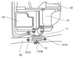
- FIG. 4 is a top view of the first mount fixing part 11 that mounts and fixes the electric unit 10 to the side member 50
- FIG. 5 is a top view of the second mount fixing part 12 that mounts and fixes the electric unit 10 to the suspension member 60. Note that FIG. 5 is a view of the state in which the motor housing 41 is not fastened to the gearbox housing 43.
- the mount member of the first mount fixing portion 11 is fastened to the side member 50 at three points (131A, 131B, 131C).
- the second mount fixing portion 12 has two mount members each fastened to the suspension 102. That is, the mount member of the second mount fixing portion 12 is fastened to the suspension member 60 at two points (141A, 141B).
- the fastening points can be regarded as the fixed points.
- the center of gravity of the multiple points can be regarded as the fixed points that mount and fix the electric unit 10 to the vehicle body, with the center of gravity being the representative point.
- the midpoint of the two points can be regarded as the fixed points that mount and fix the electric unit 10 to the vehicle body, with the midpoint being the representative point.
- the mount member of the first mount fixing part 11 is fastened to the side member 50 at three points (131A, 131B, 131C), and therefore the center of gravity of the three points (131A, 131B, 131C) is set as the first fixed point 13.
- the mount member of the second mount fixing part 12 is fastened to the suspension member 60 at two points (141A, 141B), the midpoint of the two points (141A, 141B) is set as the second fixing point 14.
- the mount member of the mount fixing part may be divided into multiple parts and installed, as in the case of the second mount fixing part 12 of this embodiment.
- the mount member of the first mount fixing portion 11 is fastened to the side member 50 at three points (131A, 131B, 131C), and the mount member of the second mount fixing portion 12 is fastened to the suspension member 60 at two points (141A, 141B), but this is not limited to this.
- the number of fastening points for fastening the mount members to the side member 50 and the suspension member 60 can be determined as desired.
- one fixing part is set for fixing the electric unit 10 to each of the side member 50 and the suspension member 60, but multiple fixing parts may be set for fixing the electric unit 10 to each of the side member 50 and the suspension member 60.
- the reinforcing part 44 is provided rearward in a top view of the vehicle 100 from a straight line connecting a fixing point in the fixing part interposed between the electric motor 21 and the side member 50 and a fixing point in the fixing part interposed between the gear box 3 and the suspension member 60.
- the fixing point set between the electric motor 21 and the side member 50 is the first fixing point 13
- the fixing point set between the gear box 3 and the suspension member 60 is the second fixing point 14.
- FIG. 6 is a left side view of the case 4, showing the positional relationship between the side member 50 and the reinforcing portion 44.
- the position of the side member 50 in the height direction and the front-rear direction of the electric vehicle 100 is shown by dashed lines.
- the side member 50 has different plate thicknesses or material strengths at the boundary portion 51 in the fore-and-aft direction of the vehicle 100. In other words, the side member 50 has two different types of rigidity in the fore-and-aft direction of the vehicle 100.
- the reinforcing portion 44 is provided at a position that overlaps with the side member 50 of the vehicle 100 in the height direction of the vehicle 100.
- the side member 50 will interfere with the portion having the reinforcing portion 44 with enhanced rigidity. In other words, it is possible to prevent the side member 50 from interfering with a portion with weak strength, causing damage to the case 4.
- the reinforcing portion 44 is provided at a position overlapping the boundary portion 51 where the rigidity of the side member 50 changes in a side view of the vehicle 100.
- the side member 50 is likely to bend at the boundary portion 51 where the rigidity changes. That is, in a collision, the boundary portion 51 becomes a bending point and an edge, so that when the case 4 interferes with the boundary portion 51 (edge) of the side member 50 in a collision, the stress generated at the interfered portion increases, and the case 4 is likely to be damaged.
- the reinforcing portion 44 at a position overlapping the boundary portion 51 of the side member 50 in a side view of the vehicle 100, even if the case 4 interferes with the side member 50 in a collision of the vehicle 100, the boundary portion 51 (edge) of the side member 50 interferes with the portion having the reinforcing portion 44. Therefore, damage to the case 4 can be suppressed.
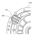
- Figure 7 is an enlarged view of a portion of the rear cover 413 in the motor housing 41, which constitutes part of the case 4, and shows the inside of the rear cover 413.
- the inside of the rear cover 413 is configured in a honeycomb shape.
- a rib-shaped member (hereinafter referred to as a rib) 441 is provided on the inside of the rear cover 413, and the rigidity is strengthened in the area having the rib 441. That is, the rib 441 provided on the rear cover 413 forms the reinforcing portion 44 of the case 4. Therefore, when the rear cover 413 is fastened to the outer housing 412, the rib 441 is provided at a position that is rearward of the straight line connecting the fixed points.
- the reinforcing portion 44 is provided in a rib shape on the inside of the case 4, there is no need to secure space for providing the reinforcing portion 44 on the outside of the case 4. Therefore, it is possible to further save space in the case 4, and while securing the vehicle body crush stroke and clearance, damage to the case 4 during a collision of the vehicle 100 can be suppressed.
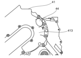
- FIG. 8 is a partially enlarged view of the electric unit 10 (ePT2) before the rear cover 413 is fastened, and is a side view of the portion where the electric motor 21 is housed in the motor housing 41.
- FIG. 9 is a partially enlarged view of the electric unit 10 (ePT2) after the rear cover 413 is fastened, and is a side view of the portion where the electric motor 21 is housed in the motor housing 41.
- the first inner housing 411A that houses the electric motor 21 has a flange portion 4112 formed on the outer periphery, and is fastened to the outer housing 412 at multiple points by bolts or the like.
- the rib 441 (reinforcement portion 44) is provided on the inside of the rear cover 413, at a position rearward of the straight line connecting the fixed points, and at a position opposite the fastening portion 414 where the first inner housing 411A and the outer housing 412 are fastened (position indicated by Y in FIG. 9).
- the reinforcement portion 44 By providing the reinforcement portion 44 at a position opposite the fastening portion 414 in this way, the strength of the bolts fastening the first inner housing 411A and the outer housing 412 also contributes to the rigidity of the reinforcement portion 44. In other words, the rigidity of the reinforcement portion 44 can be further strengthened, and damage to the case 4 in the event of a collision of the vehicle 100 can be further suppressed.
- Figure 10 is a cross-sectional view of the fastening portion 414 between the first inner housing 411A and the outer housing 412 that house the electric motor 21, and the surrounding area, as viewed from the rear side of the vehicle 100.
- the first inner housing 411A and the outer housing 412 are fastened by bolts 81 at the fastening portion 414.
- the outer housing 412 and the rear cover 413 are fastened by bolts 82, and a rib 441 constituting the reinforcing portion 44 is provided on the inside of the rear cover 413 at a position facing the bolt 81.
- the high-voltage portion 211 of the electric motor 21 is located on the inside of the inner circumferential surface of the first inner housing 411A.
- the strength of the bolt 81 also contributes to the rigidity of the reinforcing portion 44, as described above.
- the fastening portion 414 has a tap portion for the bolt 81, a thickness equivalent to the depth of the hole is required, and rigidity is ensured in the direction in which the bolt 81 is inserted. Therefore, the rigidity of the reinforcing portion 44 is essentially strengthened, and damage to the case 4 in the event of a collision of the vehicle 100 can be further suppressed.
- the rib 441 is provided at a position facing the bolt 81 of the fastening portion 414, even if the case 4 breaks during a collision of the vehicle 100, the rib 441 makes it difficult for fingers to get inside the case 4 (motor housing 41), preventing electric shock to the driver, etc.
- the rib 441 is configured in a shape having fine rib holes with a pitch narrower than that of a human finger, for example. This makes it possible to further prevent fingers from getting inside the case 4 (motor housing 41) and getting an electric shock if the case 4 breaks.
- the electric vehicle 100 of the above embodiment can provide the following advantages.
- the electric unit 10 which includes an electric motor (electric motor) 21 and a case 4 that houses the electric motor (electric motor) 21, is mounted and fixed to the vehicle body at multiple fixed points.
- the multiple fixed points include a first fixed point 13 set on a side member 50 located on the side of the electric vehicle 100 with respect to the electric unit 10, and a second fixed point 14 set on a suspension member 60 located on the rear side of the electric vehicle 100.
- the case 4 has a reinforcement part 44 with enhanced rigidity at a portion located rearward of the electric vehicle 100 from the straight line L-L connecting the first fixed point 13 and the second fixed point 14, when viewed from above the electric vehicle 100.
- the side member 50 will interfere with the portion of the case 4 with the reinforcement part 44 with enhanced rigidity. Therefore, damage or breakage of the case 4 is suppressed in the event of a collision of the electric vehicle 100.
- the reinforcing portion 44 since the reinforcing portion 44 only needs to be provided in the area rearward of the straight line connecting the fixed points, the space required for the case 4 can be reduced, and the vehicle body crush stroke and clearance can be ensured.
- the reinforcing portion 44 of the case 4 is provided at a position that overlaps with the side member 50 in the height direction of the electric vehicle 100.
- the side member 50 has two types of rigidity in the front-to-rear direction of the electric vehicle 100, and the reinforcing portion 44 of the case 4 is provided at a position that overlaps with the boundary portion 51 where the rigidity of the side member 50 changes.
- the reinforcing portion 44 is provided in a rib shape on the inside of the case 4. Therefore, since there is no need to secure space for providing the reinforcing portion 44 on the outside of the case 4, it is possible to further reduce the space required for the case 4. In other words, it is possible to suppress damage to the case 4 when the electric vehicle 100 collides while securing the vehicle body crush stroke and clearance.
- the rib-shaped reinforcement portion 44 is provided at a position facing the fastening portion 414 between the inner housing 411 and the outer housing 412 in the rear cover 413.
- the strength of the bolts fastening the inner housing 411 and the outer housing 412 also contributes to the rigidity of the reinforcement portion 44, so that damage to the case 4 during a collision of the electric vehicle 100 can be further suppressed.
- the fastening portion 414 needs to have a thickness equivalent to the depth of the hole into which the bolts are inserted, the rigidity of the reinforcement portion 44 is substantially strengthened, and damage to the case 4 during a collision of the vehicle 100 can be further suppressed.
- the rib-shaped reinforcement portion 44 is provided at a position facing the fastening portion 414, even if the case 4 breaks during a collision of the vehicle 100, the reinforcement portion 44 makes it difficult for fingers to enter the inside of the case 4. Therefore, electric shock to the driver, etc. can be prevented.
- the case 4 is configured by integrating the motor housing 41 that houses the electric motor 21 and the generator 22, the inverter housing 42 that houses the inverter 23, and the gearbox housing 43 that houses the gear train of the gearbox 3, but is not limited to this.
- the case 4 may be any housing that houses at least the electric motor 21.
- the electric motor 21 and generator 22 of the ePT2 are integrated with the inverter 23, but this is not limited thereto, and as long as the electric motor 21 and generator 22 are electrically connected to the inverter 23, they do not have to be integrated with the inverter 23. Also, like an electric vehicle that does not have a generator, the ePT2 does not have to be equipped with a generator 22.
- the first mount fixing portion 11 (first fixing point 13) is mounted and fixed to the side member 50 located on the left side of the electric vehicle 100, but this is not limited to this.
- the electric unit 10 is likely to interfere with the side member 50 located on the left side of the electric vehicle 100 because a load is applied from a position on the left side of the front of the electric vehicle 100 and the electric unit 10 rotates in a yaw motion.
- the first fixing point 13 on the side member 50 located on the left side of the electric vehicle 100.
- the side member on which side of the electric vehicle 100 the first fixing point 13 is to be set can be determined arbitrarily depending on the region in which the electric vehicle 100 is used, etc.
- the reinforcing portion 44 is preferably provided at a position overlapping the side member 50 in the height direction of the electric vehicle 100, but this is not necessarily limited to this. As long as it is provided at a location rearward of the straight line connecting the fixed points, the reinforcing portion 44 may be provided at a position offset from the side member 50 in the height direction of the electric vehicle 100.
- the reinforcing portion 44 is preferably provided at a position overlapping the boundary portion 51 where the rigidity of the side member 50 changes in a side view of the electric vehicle 100, but is not necessarily limited to this. As long as the reinforcing portion 44 is provided at a position rearward of the straight line connecting the fixed points, the reinforcing portion 44 may be provided at a position offset from the boundary portion 51 in a side view of the electric vehicle 100.
- the side member 50 has two types of rigidity in the front-rear direction of the electric vehicle 100, but this is not limited thereto, and the side member 50 may have only one type of rigidity, or may have three or more types of rigidity.
- the reinforcing portion 44 is preferably provided at a position overlapping one of a number of boundary portions where the rigidity of the side member 50 changes, when viewed from the side of the electric vehicle 100.
- the reinforcing portion 44 is provided in a rib shape on the inside of the case 4 (rear cover 413), but this is not necessarily limited to this. As long as the reinforcing portion 44 is provided in a portion rearward of the straight line connecting the fixed points, it does not have to be in a rib shape, and it may also be provided on the outside of the case 4.
Landscapes
- Engineering & Computer Science (AREA)
- Chemical & Material Sciences (AREA)
- Combustion & Propulsion (AREA)
- Transportation (AREA)
- Mechanical Engineering (AREA)
- Arrangement Or Mounting Of Propulsion Units For Vehicles (AREA)
Abstract
Description
図1は、本発明の実施形態による電動車両(以下、車両とも言う)100に搭載される電動ユニット10の主要構成を示す概略構成図であり、車両100の上面から見た図である。なお、図1の左側が車両100の前方方向である。本実施形態において、電動車両100は、不図示のエンジンにより駆動されて発電する発電機(発電モータ)22と、不図示のバッテリからの電力により駆動することで電動車両100を走行させる電動機(駆動モータ)21とを備える、いわゆるシリーズハイブリッド車両である。但し、これに限られず、他のハイブリッド車両でもよく、また、例えば、エンジン及び発電機(発電モータ)を有していない電気自動車等であってもよい。
Claims (5)
- 電動モータと、前記電動モータを収容するケースとを備える電動ユニットが、複数の固定点において車体にマウント固定される電動車両であって、
前記固定点は、少なくとも、前記電動ユニットに対し、前記電動車両の側面側に位置するサイドメンバに設定される第1の固定点と、前記電動ユニットに対し、前記電動車両の後方側に位置するサスペンションメンバに設定される第2の固定点とを含み、
前記ケースは、前記第1の固定点と、前記第2の固定点とを結ぶ直線に対し、前記電動車両の上面視で、当該直線よりも前記電動車両の後方側にある部位に剛性を強化した補強部を有する、
電動車両。 - 請求項1に記載の電動車両であって、
前記補強部は、前記電動車両の高さ方向において、前記サイドメンバと重なる位置に設けられる、
電動車両。 - 請求項2に記載の電動車両であって、
前記サイドメンバは、前記電動車両の前後方向で少なくとも2種の剛性を有し、
前記補強部は、前記電動車両の側面視で、前記サイドメンバの剛性が変わる境界部と重なる位置に設けられる、
電動車両。 - 請求項1に記載の電動車両であって、
前記補強部は、前記ケースの内側に、リブ形状に設けられる、
電動車両。 - 請求項4に記載の電動車両であって、
前記ケースは、アウターハウジングと、前記アウターハウジングの内側に収容されるとともに、前記アウターハウジングに締結される筒状のインナーハウジングと、前記インナーハウジングの開口を覆うリアカバーとから構成され、
前記補強部は、前記リアカバーにおける、前記インナーハウジングと前記アウターハウジングとの締結部と対向する位置に設けられる、
電動車両。
Priority Applications (4)
| Application Number | Priority Date | Filing Date | Title |
|---|---|---|---|
| EP23942619.0A EP4733101A1 (en) | 2023-06-26 | 2023-06-26 | Electric vehicle |
| JP2025529023A JPWO2025004150A1 (ja) | 2023-06-26 | 2023-06-26 | |
| CN202380099454.6A CN121335814A (zh) | 2023-06-26 | 2023-06-26 | 电动车辆 |
| PCT/JP2023/023632 WO2025004150A1 (ja) | 2023-06-26 | 2023-06-26 | 電動車両 |
Applications Claiming Priority (1)
| Application Number | Priority Date | Filing Date | Title |
|---|---|---|---|
| PCT/JP2023/023632 WO2025004150A1 (ja) | 2023-06-26 | 2023-06-26 | 電動車両 |
Publications (1)
| Publication Number | Publication Date |
|---|---|
| WO2025004150A1 true WO2025004150A1 (ja) | 2025-01-02 |
Family
ID=93938117
Family Applications (1)
| Application Number | Title | Priority Date | Filing Date |
|---|---|---|---|
| PCT/JP2023/023632 Ceased WO2025004150A1 (ja) | 2023-06-26 | 2023-06-26 | 電動車両 |
Country Status (4)
| Country | Link |
|---|---|
| EP (1) | EP4733101A1 (ja) |
| JP (1) | JPWO2025004150A1 (ja) |
| CN (1) | CN121335814A (ja) |
| WO (1) | WO2025004150A1 (ja) |
Citations (5)
| Publication number | Priority date | Publication date | Assignee | Title |
|---|---|---|---|---|
| WO2014148410A1 (ja) * | 2013-03-18 | 2014-09-25 | 日立オートモティブシステムズ株式会社 | 電気自動車用駆動装置 |
| JP2018016247A (ja) | 2016-07-29 | 2018-02-01 | 日産自動車株式会社 | 電動車両のパワーユニット構造 |
| JP2019085088A (ja) * | 2017-11-02 | 2019-06-06 | トヨタ自動車株式会社 | 車両用高電圧ユニットの支持構造および車両前部構造 |
| JP2019098939A (ja) * | 2017-12-01 | 2019-06-24 | トヨタ自動車株式会社 | 車両の後部構造 |
| JP2021046010A (ja) * | 2019-09-17 | 2021-03-25 | トヨタ自動車株式会社 | 燃料電池スタックの車両搭載構造及び車両搭載方法 |
Family Cites Families (6)
| Publication number | Priority date | Publication date | Assignee | Title |
|---|---|---|---|---|
| TWI341264B (en) * | 2006-09-28 | 2011-05-01 | Mitsubishi Motors Corp | Electric motor mounting structure for vehicles |
| US7886861B2 (en) * | 2007-09-06 | 2011-02-15 | Mitsubishi Jidosha Kogyo Kabushiki Kaisha | Electric vehicle |
| JP5800214B2 (ja) * | 2011-02-23 | 2015-10-28 | スズキ株式会社 | 電気自動車のパワーユニット懸架構造 |
| WO2013168227A1 (ja) * | 2012-05-08 | 2013-11-14 | トヨタ自動車株式会社 | 電気自動車 |
| DE102017220208B4 (de) * | 2017-11-14 | 2020-04-09 | Audi Ag | Fahrzeugachse für ein zweispuriges Fahrzeug |
| EP4434789A4 (en) * | 2021-11-17 | 2025-02-26 | Nissan Motor Co., Ltd. | ENGINE MOUNTING SYSTEM |
-
2023
- 2023-06-26 WO PCT/JP2023/023632 patent/WO2025004150A1/ja not_active Ceased
- 2023-06-26 JP JP2025529023A patent/JPWO2025004150A1/ja active Pending
- 2023-06-26 CN CN202380099454.6A patent/CN121335814A/zh active Pending
- 2023-06-26 EP EP23942619.0A patent/EP4733101A1/en active Pending
Patent Citations (5)
| Publication number | Priority date | Publication date | Assignee | Title |
|---|---|---|---|---|
| WO2014148410A1 (ja) * | 2013-03-18 | 2014-09-25 | 日立オートモティブシステムズ株式会社 | 電気自動車用駆動装置 |
| JP2018016247A (ja) | 2016-07-29 | 2018-02-01 | 日産自動車株式会社 | 電動車両のパワーユニット構造 |
| JP2019085088A (ja) * | 2017-11-02 | 2019-06-06 | トヨタ自動車株式会社 | 車両用高電圧ユニットの支持構造および車両前部構造 |
| JP2019098939A (ja) * | 2017-12-01 | 2019-06-24 | トヨタ自動車株式会社 | 車両の後部構造 |
| JP2021046010A (ja) * | 2019-09-17 | 2021-03-25 | トヨタ自動車株式会社 | 燃料電池スタックの車両搭載構造及び車両搭載方法 |
Non-Patent Citations (1)
| Title |
|---|
| See also references of EP4733101A4 |
Also Published As
| Publication number | Publication date |
|---|---|
| JPWO2025004150A1 (ja) | 2025-01-02 |
| CN121335814A (zh) | 2026-01-13 |
| EP4733101A4 (en) | 2026-04-29 |
| EP4733101A1 (en) | 2026-04-29 |
Similar Documents
| Publication | Publication Date | Title |
|---|---|---|
| US11492044B2 (en) | Vehicle front structure | |
| CN107804149B (zh) | 车辆用设备的安装构造 | |
| JP5272405B2 (ja) | 車載電気機器収容ケース | |
| JP2013193634A (ja) | 電動車両 | |
| JP7517588B2 (ja) | 電動ユニットの車載構造 | |
| JP7480835B2 (ja) | インバータの車載構造 | |
| WO2025004150A1 (ja) | 電動車両 | |
| WO2020240804A1 (ja) | ハイブリッド電気自動車 | |
| JP5929749B2 (ja) | 車載機器の搭載構造 | |
| EP4365032B1 (en) | Electric vehicle | |
| JP2013193652A (ja) | 電動車両 | |
| JP7189716B2 (ja) | 車両 | |
| US12597865B2 (en) | Inverter | |
| US20250178456A1 (en) | Drive unit for electric vehicle | |
| JP2015044566A (ja) | 車両用の回転電機 | |
| JP7435730B2 (ja) | 電動ユニットの車載構造 | |
| JP7373455B2 (ja) | プロテクター構造体を備えた電動ユニット | |
| CN121175207A (zh) | 电动车辆 | |
| KR20250176519A (ko) | 기전 일체 유닛 및 전동 차량 | |
| WO2023188518A1 (ja) | 車両の前部構造 | |
| WO2026018333A1 (ja) | 電動車両 | |
| JP2024017329A (ja) | トランスアクスルケース搭載構造 | |
| JP2023173571A (ja) | 駆動用バッテリの支持装置 | |
| JP2021046009A (ja) | 電動車両のパワーユニット搭載部構造 |
Legal Events
| Date | Code | Title | Description |
|---|---|---|---|
| 121 | Ep: the epo has been informed by wipo that ep was designated in this application |
Ref document number: 23942619 Country of ref document: EP Kind code of ref document: A1 |
|
| ENP | Entry into the national phase |
Ref document number: 2025529023 Country of ref document: JP Kind code of ref document: A |
|
| WWE | Wipo information: entry into national phase |
Ref document number: 2025529023 Country of ref document: JP |
|
| ENP | Entry into the national phase |
Ref document number: 2023942619 Country of ref document: EP Effective date: 20260126 |
|
| WWE | Wipo information: entry into national phase |
Ref document number: 2023942619 Country of ref document: EP |
|
| NENP | Non-entry into the national phase |
Ref country code: DE |
|
| ENP | Entry into the national phase |
Ref document number: 2023942619 Country of ref document: EP Effective date: 20260126 |
|
| ENP | Entry into the national phase |
Ref document number: 2023942619 Country of ref document: EP Effective date: 20260126 |