WO2025004431A1 - モータの製造方法及びモータ - Google Patents
モータの製造方法及びモータ Download PDFInfo
- Publication number
- WO2025004431A1 WO2025004431A1 PCT/JP2024/004409 JP2024004409W WO2025004431A1 WO 2025004431 A1 WO2025004431 A1 WO 2025004431A1 JP 2024004409 W JP2024004409 W JP 2024004409W WO 2025004431 A1 WO2025004431 A1 WO 2025004431A1
- Authority
- WO
- WIPO (PCT)
- Prior art keywords
- end plate
- resin
- hole
- uncured resin
- motor
- Prior art date
- Legal status (The legal status is an assumption and is not a legal conclusion. Google has not performed a legal analysis and makes no representation as to the accuracy of the status listed.)
- Ceased
Links
Images




Classifications
-
- H—ELECTRICITY
- H02—GENERATION; CONVERSION OR DISTRIBUTION OF ELECTRIC POWER
- H02K—DYNAMO-ELECTRIC MACHINES
- H02K15/00—Processes or apparatus specially adapted for manufacturing, assembling, maintaining or repairing of dynamo-electric machines
- H02K15/12—Impregnating, moulding insulation, heating or drying of windings, stators, rotors or machines
- H02K15/121—Impregnating, moulding insulation, heating or drying of windings, stators, rotors or machines of cores
-
- H—ELECTRICITY
- H02—GENERATION; CONVERSION OR DISTRIBUTION OF ELECTRIC POWER
- H02K—DYNAMO-ELECTRIC MACHINES
- H02K15/00—Processes or apparatus specially adapted for manufacturing, assembling, maintaining or repairing of dynamo-electric machines
- H02K15/14—Casings; Enclosures; Supports
-
- H—ELECTRICITY
- H02—GENERATION; CONVERSION OR DISTRIBUTION OF ELECTRIC POWER
- H02K—DYNAMO-ELECTRIC MACHINES
- H02K1/00—Details of the magnetic circuit
- H02K1/06—Details of the magnetic circuit characterised by the shape, form or construction
- H02K1/12—Stationary parts of the magnetic circuit
- H02K1/14—Stator cores with salient poles
-
- H—ELECTRICITY
- H02—GENERATION; CONVERSION OR DISTRIBUTION OF ELECTRIC POWER
- H02K—DYNAMO-ELECTRIC MACHINES
- H02K15/00—Processes or apparatus specially adapted for manufacturing, assembling, maintaining or repairing of dynamo-electric machines
- H02K15/12—Impregnating, moulding insulation, heating or drying of windings, stators, rotors or machines
- H02K15/122—Impregnating, moulding insulation, heating or drying of windings, stators, rotors or machines of windings
-
- H—ELECTRICITY
- H02—GENERATION; CONVERSION OR DISTRIBUTION OF ELECTRIC POWER
- H02K—DYNAMO-ELECTRIC MACHINES
- H02K15/00—Processes or apparatus specially adapted for manufacturing, assembling, maintaining or repairing of dynamo-electric machines
- H02K15/12—Impregnating, moulding insulation, heating or drying of windings, stators, rotors or machines
- H02K15/123—Impregnating, moulding insulation, heating or drying of windings, stators, rotors or machines of casings or enclosures
-
- H—ELECTRICITY
- H02—GENERATION; CONVERSION OR DISTRIBUTION OF ELECTRIC POWER
- H02K—DYNAMO-ELECTRIC MACHINES
- H02K3/00—Details of windings
- H02K3/04—Windings characterised by the conductor shape, form or construction, e.g. with bar conductors
- H02K3/18—Windings for salient poles
-
- H—ELECTRICITY
- H02—GENERATION; CONVERSION OR DISTRIBUTION OF ELECTRIC POWER
- H02K—DYNAMO-ELECTRIC MACHINES
- H02K5/00—Casings; Enclosures; Supports
- H02K5/04—Casings or enclosures characterised by the shape, form or construction thereof
Definitions
- This disclosure relates to a motor manufacturing method and a motor.
- the motor comprises a rotor, which is a rotating body, and a stator arranged around the rotor.
- the stator has a core and a coil wound around the core.
- the stator is sealed with resin to waterproof and rust-proof the coil, which is a conductor.
- Patent documents 1 to 3 disclose motor-related technologies.
- Patent document 1 discloses a manufacturing method for a PM motor. In the manufacturing method disclosed in Patent document 1, after the coil is placed on the inner diameter side of the stator core, resin is injected from a mold injection port. The injected resin is then hardened by heating or the like to form a molded resin layer that covers the stator core and coil.
- Patent documents 2 and 3 disclose technologies for fixing magnets with resin.
- resins with high thermal conductivity have high viscosity when uncured. If such uncured resin is poured into a configuration in which a stator is placed in a housing, it takes a long time for the resin to permeate the gaps. Furthermore, if a resin with a short pot life is used, the resin may harden before filling is complete.
- the resin As a heat path, it is desirable for the resin to be in contact with the coil as well as the case that houses the coil. Even if the resin is in contact with the coil, if it is not in contact with the case, the gap between the resin and the case will become a thermal resistor. As a result, it will not function adequately as a heat path.
- the present disclosure provides a method for manufacturing a motor that can easily dissipate heat to the outside in a short period of time, and a motor that easily dissipates heat to the outside.
- a motor manufacturing method includes an attachment step of attaching an end plate having a first end plate through hole and a second end plate through hole to a housing containing a stator with a coil wound around it, a first injection step of pouring uncured resin into a stator arrangement area of the housing containing the stator from the first end plate through hole, which allows a first portion of the coil to be visible from outside the housing, after the attachment step, and a second injection step of pouring uncured resin into the stator arrangement area of the housing from the second end plate through hole, which allows a second portion of the coil different from the first portion to be visible from outside the housing.
- uncured resin is poured in after the end plates are attached.
- the uncured resin is poured into the stator arrangement area through a process of pouring it in through a first end plate through hole and a process of pouring it in through a second end plate through hole that is different from the first end plate through hole.
- the uncured resin may be exposed from at least one of the first end plate through hole or the second end plate through hole by repeating the first injection step and the second injection step.
- the uncured resin is exposed from at least one of the first end plate through hole or the second end plate through hole, the uncured resin is in contact with the rear surface of the end plate. Therefore, a path for transferring heat from the coil to the end plate via the resin can be reliably formed.
- a method of manufacturing a motor includes an injection step of pouring uncured resin from an opening in the housing into a plurality of different locations in a stator arrangement area of the housing that contains a stator with a coil wound around it, and an attachment step of attaching an end plate having a first end plate through hole and a second end plate through hole after the injection step.
- the end plate attachment step the end plate is pressed against the liquid surface of the uncured resin to expose the uncured resin from the first end plate through hole and/or the second end plate through hole.
- uncured resin is poured into the stator arrangement area from multiple different positions. Therefore, it takes less time for the uncured resin to spread throughout the stator arrangement area than if the uncured resin was poured from one position. Then, after pouring the uncured resin, the end plates are attached. When attaching the end plates, the end plates are pressed against the liquid surface of the uncured resin, exposing the uncured resin from the first end plate through hole and/or the second end plate through hole. Pressing the end plates to expose the uncured resin from the first end plate through hole and/or the second end plate through hole means that the back surface of the end plate is in contact with the uncured resin. Therefore, a motor that easily releases heat to the outside can be manufactured in a short time.
- the injection step may involve continuously pouring in uncured resin while rotating the housing and the device for supplying the uncured resin relatively around the axis of the housing. This step also shortens the time it takes for the uncured resin to spread throughout the stator placement area.
- the injection step may include a step of pouring a predetermined amount of uncured resin into a first portion of the coil, and a step of pouring a predetermined amount of uncured resin into a second portion of the coil that is different from the first portion. This step also shortens the time it takes for the uncured resin to spread throughout the stator arrangement area.
- a motor includes a stator wound with a coil, a rotor surrounded by the stator and rotating with the shaft, a housing that receives the stator and rotor through a housing opening and forms a stator arrangement area that accommodates the received stator, an end plate attached to the housing opening, and a resin portion filled in the stator arrangement area.
- the resin portion contacts the coil and the end plate.
- the end plate includes a plurality of end plate through holes that expose the resin portion.
- the resin part is in contact with both the coil and the end plate.
- the exposed surface of the resin portion exposed from the end plate through hole may be located between the edge of the opening on the back surface side of the end plate and the edge of the opening on the main surface side of the end plate.
- the end plate of the motor may include an annular inner cylindrical portion including an end plate shaft insertion hole through which the shaft is inserted, an annular outer cylindrical portion that circumferentially surrounds the inner cylindrical portion and has an inner diameter larger than the outer diameter of the inner cylindrical portion, and a plurality of connecting portions arranged at intervals around the axis of the shaft so as to connect the outer peripheral surface of the inner cylindrical portion to the inner peripheral surface of the outer cylindrical portion.
- the end plate through hole may be an area sandwiched between a pair of connecting portions adjacent to each other around the axis of the shaft.
- the end face of the inner cylindrical portion may protrude from the connecting portion along the axial direction of the shaft.
- the motor manufacturing method disclosed herein allows for the manufacture of a motor that easily releases heat to the outside in a short period of time.
- the motor disclosed herein allows for the efficient release of heat to the outside.
- FIG. 1 is a cross-sectional view showing the structure of a motor according to the present disclosure.
- FIG. 2 is a cross-sectional perspective view showing a main portion of an end plate provided in the motor shown in FIG.
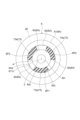
- FIG. 3 is a front view of the motor shown in FIG.
- Fig. 4(a) is a cross-sectional view showing an example of a resin portion exposed surface
- Fig. 4(b) is a cross-sectional view showing another example of a resin portion exposed surface.
- FIG. 5 is a flowchart of the first motor manufacturing method.
- Fig. 6(a) is a diagram showing a process of housing the motor assembly in a vacuum chamber
- FIG. 6(b) is a diagram showing a process of pouring uncured resin through a first end plate through-hole.
- Fig. 7(a) is a diagram showing a process of pouring uncured resin through a second end plate through hole
- Fig. 7(b) is a diagram showing a state in which it is determined that the exposed surface of the resin portion of the uncured resin material has reached a specified position.
- FIG. 8 is a flowchart of the second motor manufacturing method.
- FIG. 9 is a diagram showing an example of the first portion, the second portion, and the third portion.
- FIG. 1 is a cross-sectional view showing the structure of a motor 1 according to the present disclosure.
- Motor 1 is used, for example, in a vehicle supercharger.
- motor 1 imparts torque to shaft 2 to compensate for the torque deficiency.
- an impeller (not shown) is attached to the end of shaft 2.
- the motor 1 is, for example, a brushless AC motor.
- the motor 1 includes a shaft 2, a motor rotor 3, a motor stator 4, a housing 5, and an end plate 6.
- the vehicle's battery can be used as the driving source for the motor 1.
- the motor 1 may generate regenerative power using the rotational energy of the motor rotor 3.
- the motor 1 is capable of handling high-speed rotation of the shaft 2 (for example, 100,000 to 200,000 rpm).
- the motor rotor 3 which is a so-called rotor, is disposed between a pair of bearings 21, 22 arranged along the direction of the axis A.
- the main element constituting the motor rotor 3 is a cylindrical magnet.
- the motor rotor 3 may include elements for transmitting the torque acting on the magnet to the shaft 2 as necessary.
- the motor rotor 3 may include end rings disposed on both ends of the cylindrical magnet, or an armor ring covering the outer circumferential surface of the magnet, as necessary.
- the motor stator 4 which is a so-called stator, is housed in the housing 5.
- the motor stator 4 is arranged so as to surround the motor rotor 3 in the circumferential direction.
- the motor stator 4 includes a core 4A and a coil 4B. When a current is supplied to the coil 4B, the coil 4B generates a magnetic field. This magnetic field exerts a circumferential force on the magnet of the motor rotor 3. As a result, a torque is applied to the shaft 2.
- the housing 5 is formed inside with a motor stator arrangement area 511 (stator arrangement area) and a motor rotor arrangement area 512.
- the motor stator arrangement area 511 is an area surrounded by the cylindrical portion 51.
- the cylindrical motor stator 4 is fixed to the inner peripheral surface of the cylindrical portion.
- the housing opening 51h is blocked by an end plate 6. "Blocked” here means that the position of the components housed inside the housing 5 is maintained.
- the disk-shaped end plate 6 is fixed to the end of the housing 5.
- a bearing 21 is fixed to the end plate 6.
- the shape of the end plate 6 is a substantially circular plate.
- the end plate 6 has an end plate body 6A and an end plate flange 6F.
- the end plate body 6A is fitted into the opening recess 51ha of the housing 5.
- the end plate flange 6F abuts against the housing opening end surface 51s.
- the end plate flange 6F is provided with several bolt through holes (not shown). Bolts inserted into the bolt through holes are screwed into screw holes provided in the housing opening end surface 51s. As a result, the end plate 6 is fixed to the housing 5.
- the end plate body 6A has an outer circumferential cylindrical portion 61, spokes 62 (connecting portion), and an inner circumferential cylindrical portion 63.
- the outer circumferential cylindrical portion 61 is a portion integrated with the end plate flange 6F described above.
- the outer circumferential cylindrical portion 61 has an outer circumferential annular portion 611 and an outer circumferential upright portion 612.
- the outer circumferential upright portion 612 stands up from the outer circumferential annular portion main surface 611a of the outer circumferential annular portion 611 along the direction of the axis A.
- the end plate flange 6F extends radially from the outer circumferential upright portion outer surface 611d.
- the outer circumferential annular portion main surface 611a functions as a mounting surface for mounting another device to the motor 1.
- the outer circumferential annular portion main surface 611a may be defined as being part of the end plate main surface 6a.
- An outer peripheral step 613 is formed at the corner between the outer peripheral ring portion main surface 611a and the outer peripheral ring portion inner peripheral surface 611c.
- the outer peripheral step 613 includes an outer peripheral step main surface 613a and an outer peripheral step inner peripheral surface 613c.
- the outer peripheral step main surface 613a is recessed from the outer peripheral ring portion main surface 611a.
- the outer peripheral step inner peripheral surface 613c has a larger inner diameter than the outer peripheral ring portion inner peripheral surface 611c.
- the end plate 6 has three end plate through holes 6P1, 6P2, 6P3.
- the end plate through holes 6P1, 6P2, 6P3 can be defined as an area surrounded by a part of the inner circumferential surface 611c of the outer annular portion, a part of the outer circumferential surface 63d of the inner cylindrical portion, and the spoke circumferential end surface 62c.
- the openings of the end plate through holes 6P1, 6P2, 6P3 on the end plate main surface 6a side may be defined by an edge included in the spoke circumferential end surface 62c.
- the length along the axis A of the end plate through hole 6P may be defined as the length from the end plate back surface 6b to the spoke main surface 62a.
- the spokes 62 extend from the outer annular portion inner circumferential surface 611c to the inner cylindrical portion outer circumferential surface 63d.
- the spoke main surfaces 62a are not flush with the outer annular portion main surface 611a described above.
- the height of the spoke main surfaces 62a is lower than the height of the outer annular portion main surface 611a.
- the spoke back surfaces 62b are flush with the outer annular portion back surface 611b.
- the spoke back surfaces 62b are part of the end plate back surface 6b and also form part of the heat path.
- the inner cylindrical portion 63 has an inner cylindrical portion main surface 63a, an inner cylindrical portion back surface 63b, an inner cylindrical portion inner peripheral surface 63c, and an inner cylindrical portion outer peripheral surface 63d.
- a bearing 21 is disposed on the inner cylindrical portion main surface 63a.
- the inner cylindrical portion main surface 63a is a bearing disposition surface.
- the inner cylindrical portion main surface 63a may also be defined as being part of the end plate main surface 6a.
- the inner cylindrical portion back surface 63b is flush with the outer annular portion back surface 611b and the spoke back surfaces 62b. Like the outer annular portion back surface 611b and the spoke back surfaces 62b, the inner cylindrical portion back surface 63b is also part of the end plate back surface 6b and constitutes part of the heat path. As described above, the spokes 62 are connected to part of the inner cylindrical portion outer peripheral surface 63d. Another part of the inner cylindrical portion outer peripheral surface 63d is a surface that defines the end plate through holes 6P1, 6P2, 6P3. The inner cylindrical portion inner peripheral surface 63c defines the end plate shaft insertion hole 6H through which the shaft 2 is inserted.
- An inner step portion 633 is also formed at the corner between the inner cylindrical portion main surface 63a and the inner cylindrical portion inner peripheral surface 63c.
- the inner step portion 633 includes an inner step main surface 633a and an inner step outer peripheral surface 633d.
- the inner step main surface 633a is recessed from the inner cylindrical portion main surface 63a.
- the inner step outer peripheral surface 633d has a larger outer diameter than the inner cylindrical portion outer peripheral surface 63d.
- the inner step portion 633 can also be used in cooperation with the outer step portion 613 as a portion for abutting a masking jig in a motor manufacturing method.
- the motor 1 further includes a resin portion 7.
- the resin portion 7 is filled in a motor stator arrangement region 511 in which the motor stator 4 is arranged.
- the resin portion 7 covers the coil 4B. More specifically, the resin portion 7 covers the coil ends 41 protruding from the end faces of the core 4A. With such a resin portion 7, the coil 4B does not come into direct contact with air.
- the resin portion 7 provides a waterproof function that protects the coil 4B from moisture, and also provides an anti-rust function that suppresses the occurrence of rust on the coil 4B.
- An example of such a resin is a two-component curing epoxy resin.
- the resin portion 7 includes a portion 72 filled between the coil end end face 41a and the end plate back surface 6b. More specifically, the portion 72 is in contact with the coil end end face 41a and also with the end plate back surface 6b. As a result, similar to the above, the thermal resistance from the coil end 41 to the end plate 6 is dominated by the resin portion 7.
- the resin part 7 further includes a portion 73 filled in the end plate through hole 6P.
- the surface of the resin part 7 exposed from the end plate through hole 6P is called the resin part exposed surface 73s.
- the resin part exposed surface 73s shown in FIG. 4(a) does not leak out from the end plate through hole 6P.
- the upper end of the end plate through hole 6P is defined by the opening edge 62as (the opening edge on the main surface side of the end plate) of the spoke main surface 62a.
- the lower end of the end plate through hole 6P is defined by the opening edge 6bs (the opening edge on the back surface side of the end plate) of the end plate back surface 6b.
- the resin part exposed surface 73s is located between the spoke main surface 62a and the end plate back surface 6b. According to the position of the resin part exposed surface 73s, the inner circumference side cylindrical part main surface 63a protrudes from the resin part exposed surface 73s. Therefore, the resin part 7 does not adhere to the inner circumference side cylindrical part main surface 63a. As a result, the bearing 21 can be securely attached to the inner cylindrical portion main surface 63a.
- the position of the resin part exposed surface 73s may be at least closer to the motor stator 4 than the inner peripheral cylindrical part main surface 63a.
- the resin part exposed surface 73s may be higher than the spoke main surface 62a and cover the spoke main surface 62a. Even in this case, the position of the resin part exposed surface 73s is lower than the outer peripheral annular part main surface 611a and/or the inner peripheral cylindrical part main surface 63a. Therefore, the resin part 7 does not adhere to the outer peripheral annular part main surface 611a and/or the inner peripheral cylindrical part main surface 63a. As a result, components such as the bearing 21 can be attached well to the outer peripheral annular part main surface 611a and/or the inner peripheral cylindrical part main surface 63a.
- the motor 1 can be manufactured by one of the two methods described below.
- ⁇ First Motor Manufacturing Method> 5 is a diagram showing the main steps in the manufacturing method of the first motor.
- the motor stator 4 is placed in the housing 5.
- the cylindrical member 101 (see FIG. 6(a)) is placed in the area corresponding to the motor rotor arrangement area 512. This is to prevent the motor rotor arrangement area 512 from being filled with uncured resin when the step of filling the uncured resin is carried out.
- the end plate 6 is fixed to the housing 5 (S11: see FIG. 6(a)).
- each part in the middle of assembly in each manufacturing process of the motor 1 will be referred to as a "motor assembly".
- the motor manufacturing method of this embodiment uses so-called vacuum filling to fill the uncured resin.
- uncured resin 7s is poured in through the first end plate through hole 6P1 (S13: see FIG. 6(b)).
- the motor assembly may be heated to a predetermined temperature in order to maintain the fluidity of the uncured resin 7s.
- the injection of the uncured resin 7s is stopped.
- the uncured resin 7s flows from the first end plate through hole 6P1 to the coil end 41, and then flows to the coil end 41 on the opposite side.
- static state refers to the tilted liquid surface of the uncured resin 7s reaching a horizontal position.
- step S15 it is confirmed whether the liquid level of the uncured resin 7s poured from each of the end plate through holes 6P1, 6P2, and 6P3 has reached a specified position (S16).
- This confirmation may be performed by visually checking the position of the liquid level 73k of the uncured resin 7s from the end plate through holes 6P1, 6P2, and 6P3. For example, it may be determined that the liquid level 73k of the uncured resin 7s has reached a specified position on the condition that the liquid level 73k of the uncured resin 7s has reached each of the end plate through holes 6P1, 6P2, and 6P3 as shown in FIG. 7(b).
- the injection of the uncured resin 7s is terminated. Then, the motor assembly is heated to a specified temperature. As a result, the uncured resin 7s becomes a solidified resin part 7. After that, the motor rotor 3 and bearings 21 are attached to obtain the motor 1.
- the uncured resin 7s is again injected through the first end plate through hole 6P1 (S13).
- Checking whether the liquid level 73k of the uncured resin 7s has reached a specified position may be performed at any time during each of steps S13 to S15 of pouring the uncured resin 7s. Then, when it is determined that the liquid level 73k of the uncured resin 7s has reached a specified position, the repetition of steps S13 to S15 of pouring the uncured resin 7s may be terminated and a transition may be made to the next manufacturing step.
- uncured resin 7s is poured in until it is confirmed that the liquid level of uncured resin 7s reaches each of the end plate through holes 6P1, 6P2, and 6P3.
- uncured resin 7s reaches the end plate through holes 6P1, 6P2, and 6P3, it means that the uncured resin 7s has filled up until it touches the end plate back surface 6b. Therefore, the resin portion 7 can be reliably formed between the coil end 41 and the end plate back surface 6b.
- the uncured resin 7s is poured in (S13, S14, S15) after the end plate 6 is attached to the housing 5 (S11).
- the uncured resin 7s is poured in and then the end plate 6 is attached.
- FIG. 8 is a diagram showing the main steps included in the manufacturing method of the second motor.
- the motor stator 4 is placed in the housing 5.
- the cylindrical member 101 is placed in the area corresponding to the rotor placement area 311.
- the motor assembly is then housed in the vacuum chamber 102 (S21). At this point, the end plate 6 is not attached to the motor assembly.
- uncured resin 7s is poured into the first portion 40a (see FIG. 9) (S22).
- the first portion 40a is any portion included in the motor stator arrangement area 511 exposed from the housing opening 51h (see FIG. 9). Then, after a predetermined amount of uncured resin 7s has been poured, the injection of the uncured resin 7s is stopped.
- uncured resin 7s is poured into the second portion 40b (see FIG. 9) (S23).
- the second portion 40b is an arbitrary portion of the motor stator arrangement area 511 exposed from the housing opening 51h, and is a portion different from the first portion 40a. Then, after a predetermined amount of uncured resin 7s has been poured, the injection of the uncured resin 7s is stopped.
- the third portion 40c is an arbitrary portion of the motor stator arrangement area 511 exposed from the housing opening 51h, and is a portion different from the first portion 40a and the second portion 40b. Then, after a predetermined amount of uncured resin 7s has been poured, the injection of the uncured resin 7s is stopped.
- steps S22, S23, and S24 when steps S22, S23, and S24 are performed, the injection of uncured resin 7s is stopped after a predetermined amount of uncured resin 7s is poured into each portion.
- the process may proceed to step S23 without stopping the injection of uncured resin 7s in step S22.
- the pouring position from the supply device may be changed from the first portion 40a to the second portion 40b by rotating the motor assembly by a predetermined angle while maintaining the state in which uncured resin 7s is being poured from the supply device.
- the pouring position may be changed from the first portion 40a to the second portion 40b by moving the supply device for uncured resin 7s while the motor assembly is fixed.
- step S24 it is checked whether the liquid level of the uncured resin 7s has reached a specified position (S25). This check may be performed by visually checking the position of the liquid level of the resin through the housing opening 51h.
- the injection of the uncured resin 7s is terminated. Then, the motor assembly is removed from the vacuum chamber 102. Next, the end plate 6 is fixed to the housing 5 (S26). At this time, the uncured resin 7s has reached the opening recess 51ha of the housing 5. Then, when the end plate 6 is attached to the housing opening 51h, the uncured resin 7s that has reached the opening recess 51ha flows into the end plate through holes 6P1, 6P2, and 6P3 in response to the pressure received from the end plate 6. The pressure received by the uncured resin 7s is generated by the end plate back surface 6b being in contact with the uncured resin 7s.
- the fact that the uncured resin 7s flows into the end plate through holes 6P1, 6P2, and 6P3 means that there is no gap between the end plate back surface 6b and the uncured resin 7s.
- the rear surface 6b of the end plate is in contact with the uncured resin 7s.
- the motor assembly is then heated to a predetermined temperature. After that, the motor rotor 3 and bearings 21 are attached to obtain the motor 1.
- this may be performed at any time during steps S22, S23, and S24 of pouring in uncured resin.
- Motor stators are equipped with a resin part that seals the entire structure, including the core and the wound coil, to ensure that the coil is waterproof and rust-proof.
- motors aiming for high power density may use a resin with high thermal conductivity and employ a structure in which the gaps between the stator and the motor housing, which has a water-cooling structure, are filled with resin, allowing the heat generated by the coil to be efficiently transferred to the core and case.
- the resin is poured into the case through an opening. The case is then heated to harden the resin. Two-part curing epoxy resin is often used as the resin.
- An example of a method for providing an opening is to pour in resin before assembling one of the end plates, and then assemble the end plate after the poured resin has hardened.
- Another example of a method for providing an opening is to drill a hole in the end plate.
- the manufacturing method of the first motor 1 includes an attachment step (S11) of attaching an end plate 6 having a first end plate through hole 6P1 and a second end plate through hole 6P2 to a housing 5 housing a motor stator 4 around which a coil 4B is wound, a first injection step (S13) of pouring uncured resin 7s into a motor rotor arrangement area 512 of the housing 5 housing the motor stator 4 from the first end plate through hole 6P1, through which the first portion 40a of the coil 4B is visible from the outside of the housing 5, and a second injection step (S14) of pouring uncured resin 7s into the motor rotor arrangement area 512 of the housing 5 from the second end plate through hole 6P2, through which a second portion 40b different from the first portion 40a of the coil 4B is visible from the outside of the housing 5.
- the uncured resin 7s is poured in.
- the uncured resin 7s is poured into the motor rotor arrangement area 512 through a process (S13) of pouring in through the first end plate through hole 6P1 and a process (S14) of pouring in through a second end plate through hole 6P2 different from the first end plate through hole 6P1.
- This makes it possible to shorten the time it takes for the uncured resin 7s to spread throughout the motor rotor arrangement area 512 compared to pouring in the uncured resin 7s from one location. Therefore, even if the resin part 7 has a high viscosity and high thermal conductivity, it can be shortened in time to spread throughout the motor rotor arrangement area 512. As a result, a motor 1 that easily releases heat to the outside can be manufactured in a short time.
- the manufacturing method of the first motor 1 exposes the uncured resin 7s from the first end plate through hole 6P1 and the second end plate through hole 6P2 by repeating the first injection step (S13) and the second injection step (S14).
- the uncured resin 7s is exposed from the first end plate through hole 6P1 and the second end plate through hole 6P2
- the uncured resin 7s is in contact with the back surface 6b of the end plate. Therefore, a path for transferring heat from the coil 4B to the end plate 6 via the resin portion 7 can be reliably formed.
- multiple openings are provided in the end plate 6.
- the number of openings depends on the size of the motor 1, but may be around three. After pouring uncured resin 7s from the first end plate through hole 6P1, uncured resin 7s can be poured from the next second end plate through hole 6P2 during the liquid leveling time, thereby shortening the leveling time. This improves the efficiency of motor manufacturing.
- the motor manufacturing method allows for highly viscous resin to be filled without gaps while maintaining a realistic takt time.
- the size of the end plate through hole 6P, which is the opening, can be reduced. This allows for the mounting rigidity of the bearing housing provided on the end plate 6 and the heat extraction capacity from the end plate 6 side to be maintained.
- the manufacturing method of the second motor 1 includes an injection step (S22, S23, S24) of pouring uncured resin 7s from an opening in the housing 5 into the first portion 40a, the second portion 40b, and the third portion 40c, which are different from each other, in the motor rotor arrangement area 512 of the housing 5 that contains the motor stator 4 wound with the coil 4B, and an attachment step (S26) of attaching an end plate 6 having a first end plate through hole 6P1 and a second end plate through hole 6P2 after the injection step (S22, S23, S24).
- the attachment step (S28) of the end plate 6 the end plate 6 is pressed against the liquid surface of the uncured resin 7s to expose the uncured resin 7s from the first end plate through hole 6P1 and/or the second end plate through hole 6P2.
- the uncured resin 7s is poured into the motor rotor arrangement area 512 from a plurality of different positions (S22, S23, S24). Therefore, it is possible to shorten the time until the uncured resin 7s spreads throughout the motor rotor arrangement area 512 compared to the case where the uncured resin 7s is poured from one position.
- the end plate 6 is attached (S26). When attaching the end plate 6, the end plate 6 is pressed against the liquid surface 73k of the uncured resin 7s, thereby exposing the uncured resin 7s from the first end plate through hole 6P1 and the second end plate through hole 6P2.
- the uncured resin 7s is continuously poured in while the housing 5 and the device for supplying the uncured resin 7s are rotated relatively around the axis A of the housing 5. This step also shortens the time it takes for the uncured resin 7s to spread throughout the motor rotor arrangement area 512.
- the injection steps (S22, S23, S24) of the manufacturing method of the second motor 1 include a step (S22) of pouring a predetermined amount of uncured resin 7s into the first portion 40a of the coil 4B, and a step (S23) of pouring a predetermined amount of uncured resin 7s into a second portion 40b different from the first portion 40a of the coil 4B. This step also shortens the time it takes for the uncured resin 7s to spread throughout the motor rotor arrangement area 512.
- the motor 1 comprises a motor stator 4 wound with a coil 4B, a motor rotor 3 surrounded by the motor stator 4 and rotating with the shaft, a housing 5 that receives the motor stator 4 and the motor rotor 3 through an opening in the housing 5 and forms a motor rotor arrangement area 512 that houses the received motor stator 4, an end plate 6 attached to the housing opening 5h, and a resin part 7 filled in the motor rotor arrangement area 512.
- the resin part 7 contacts the coil 4B and the end plate 6, and the end plate 6 includes a plurality of end plate through holes 6P that expose the resin part 7.
- the resin part 7 of the motor 1 is in contact with the coil 4B and the end plate 6. This configuration ensures that a path for transferring heat from the coil 4B to the end plate 6 via the resin part 7 is formed. As a result, the heat can be efficiently released to the outside.
- the resin part exposed surface 73s exposed from the multiple end plate through holes 6P is located between the opening edge 6bs on the back surface 6b of the end plate and the opening edge 62as on the main surface 6a of the end plate. This configuration makes it possible to obtain a structure in which the resin part 7 is securely in contact with the back surface 6b of the end plate.
- the end plate 6 of the motor 1 includes an annular inner cylindrical portion 63 including an end plate shaft insertion hole 6H through which the shaft 2 is inserted, an annular outer cylindrical portion 61 that circumferentially surrounds the inner cylindrical portion 63 and has an inner diameter larger than the outer diameter of the inner cylindrical portion 63, and a plurality of spokes 62 arranged at intervals around the axis A of the shaft 2 so as to connect the inner cylindrical portion outer peripheral surface 63d of the inner cylindrical portion 63 to the outer annular portion inner peripheral surface 611c of the outer cylindrical portion 61.
- Each of the plurality of end plate through holes 6P is an area sandwiched between a pair of spokes 62 adjacent to each other around the axis A of the shaft 2.
- the end face of the inner cylindrical portion 63 protrudes from the spoke 62 along the axial direction of the shaft 2. According to this structure, it is possible to prevent uncured resin 7s from adhering to the end face of the inner cylindrical portion 63, so that the end face of the inner cylindrical portion 63 can be used as a mounting surface for parts.
- each of the multiple end plate through holes 6P is formed by a spoke 62.
- Each of the multiple end plate through holes 6P may be connected by a groove that is one step lower than the mounting surface of the other component so that the resin portion 7 may adhere to it.
- mounting surfaces of other components are the outer peripheral annular portion main surface 611a and the inner peripheral cylindrical portion main surface 63a.
- a dedicated surface for applying a masking tool may be provided so that the liquid surface 73k of the foamed uncured resin 7s does not adhere to the mounting surface of the other component.
- Examples of dedicated surfaces for applying a masking tool are the outer peripheral step portion 613 and the inner peripheral step portion 633.
- the number of openings provided in the end plate 6 may be multiple.
- the resin portion 7 may be made of different types of resin materials. For example, a resin with high thermal conductivity is poured until the coil 4B is hidden. After that, a resin with low viscosity and medium thermal conductivity may be poured near the end plate 6. With this configuration, it is possible to achieve both control of the liquid level 73k and thermal conductivity. The resin may be poured without assembling the end plate, and then the end plate may be assembled before the resin hardens.
Landscapes
- Engineering & Computer Science (AREA)
- Power Engineering (AREA)
- Manufacturing & Machinery (AREA)
- Manufacture Of Motors, Generators (AREA)
Abstract
Description
エンドプレート6の形状について、さらに詳細に説明する。エンドプレート6の形状は、略円板である。エンドプレート6は、エンドプレート本体6Aと、エンドプレートフランジ6Fと、を有する。エンドプレート本体6Aは、ハウジング5の開口凹部51haにはめ込まれる。エンドプレートフランジ6Fは、ハウジング開口端面51sに当接する。エンドプレートフランジ6Fには、いくつかのボルト貫通穴(不図示)が設けられている。ボルト貫通穴に挿通されたボルトは、ハウジング開口端面51sに設けられたネジ穴にねじ込まれる。その結果、エンドプレート6はハウジング5に固定される。
図1に示すように、モータ1は、樹脂部7をさらに備えている。樹脂部7は、モータステータ4が配置されたモータステータ配置領域511に充填されている。樹脂部7は、コイル4Bを覆っている。より詳細には、樹脂部7は、コア4Aの端面から突出するコイルエンド41を覆っている。このような樹脂部7によれば、コイル4Bは、空気に直接に触れることがない。つまり、樹脂部7は、コイル4Bを水分から保護する防水機能を奏すると共に、コイル4Bに錆が発生することを抑制する防錆機能を奏する。
図5は、第1のモータの製造方法における主要な工程を示す図である。まず、ハウジング5にモータステータ4を配置する。次に、モータロータ配置領域512に相当する領域に円筒部材101(図6(a)参照)を配置する。これは、未硬化の樹脂を充填する工程を実施するときに、モータロータ配置領域512に未硬化の樹脂が充填されないようにするためのものである。ハウジング5にエンドプレート6を固定する(S11:図6(a)参照)。以下の説明では、モータ1の製造工程のそれぞれにおいて、組み立て途中であるものを説明の便宜上「モータ組立体」と称する。
第1のモータの製造方法では、ハウジング5にエンドプレート6を取り付けた(S11)後に、未硬化の樹脂7sを注ぎ入れた(S13、S14、S15)。第2のモータの製造方法では、未硬化の樹脂7sを注ぎ入れた後に、エンドプレート6を取り付ける。
従来の製造方法における背景と問題点とを指摘する。その後に、本開示のモータの製造方法及びモータの作用効果について説明する。
以上、モータの製造方法及びモータの例示について説明した。モータの製造方法及びモータは、上記の例示に限定されることなく様々な形態で実施してよい。
2 シャフト
3 モータロータ(回転子)
4 モータステータ(固定子)
4A コア
4B コイル
5 ハウジング
6 エンドプレート
6a エンドプレート主面
6b エンドプレート裏面
6P1 第1のエンドプレート貫通穴
6P2 第2のエンドプレート貫通穴
6P3 第3のエンドプレート貫通穴
62as エンドプレート主面側の開口縁
6bs エンドプレート裏面側の開口縁
7 樹脂部
51h ハウジング開口
61 外周側円筒部
62 スポーク(連結部)
63 内周側円筒部
73s 樹脂部露出面(樹脂部の露出面)
A 軸線
Claims (8)
- コイルを巻き付けた固定子を収容したハウジングに、第1のエンドプレート貫通穴及び第2のエンドプレート貫通穴が設けられたエンドプレートを取り付ける取り付け工程と、
前記取り付け工程の後に、前記ハウジングの外側から前記コイルの第1の部位を目視可能である前記第1のエンドプレート貫通穴から、前記固定子を収容した前記ハウジングの固定子配置領域に未硬化の樹脂を注ぎ入れる第1の注入工程と、
前記ハウジングの外側から前記コイルの前記第1の部位とは異なる第2の部位を目視可能である前記第2のエンドプレート貫通穴から、前記ハウジングの前記固定子配置領域に前記未硬化の樹脂を注ぎ入れる第2の注入工程と、を有する、モータの製造方法。 - 前記第1の注入工程及び前記第2の注入工程を繰り返すことにより、前記第1のエンドプレート貫通穴及び/又は前記第2のエンドプレート貫通穴から前記未硬化の樹脂を露出させる、請求項1に記載のモータの製造方法。
- コイルを巻き付けた固定子を収容したハウジングの固定子配置領域における互いに異なる複数の部位に前記ハウジングの開口から未硬化の樹脂を注ぎ入れる注入工程と、
前記注入工程の後に、第1のエンドプレート貫通穴及び第2のエンドプレート貫通穴が設けられたエンドプレートを取り付ける取り付け工程と、を有し、
前記エンドプレートを取り付ける工程では、前記エンドプレートを前記未硬化の樹脂の液面に押し付けることによって、前記第1のエンドプレート貫通穴及び/又は前記第2のエンドプレート貫通穴から前記未硬化の樹脂を露出させる、モータの製造方法。 - 前記注入工程は、前記ハウジング及び前記未硬化の樹脂を供給する装置を前記ハウジングの軸線の周りに相対的に回転させながら、前記未硬化の樹脂を連続的に注ぎ入れる、請求項3に記載のモータの製造方法。
- 前記注入工程は、
前記コイルの第1の部位に予め定めた量の前記未硬化の樹脂を注ぎ入れる工程と、
前記コイルの前記第1の部位とは異なる第2の部位に予め定めた量の前記未硬化の樹脂を注ぎ入れる工程と、を含む、請求項3に記載のモータの製造方法。 - コイルを巻き付けた固定子と、
前記固定子に囲まれて、シャフトと共に回転する回転子と、
ハウジング開口から前記固定子及び前記回転子を受け入れて、受け入れた前記固定子を収容する固定子配置領域を形成するハウジングと、
前記ハウジング開口に取り付けられるエンドプレートと、
前記固定子配置領域に充填された樹脂部と、を備え、
前記樹脂部は、前記コイルに接すると共に前記エンドプレートに接し、
前記エンドプレートは、前記樹脂部を露出させる複数のエンドプレート貫通穴を含む、モータ。 - 前記エンドプレート貫通穴から露出する前記樹脂部の露出面は、前記エンドプレートの裏面側の開口縁と前記エンドプレートの主面側の開口縁との間に位置する、請求項6に記載のモータ。
- 前記エンドプレートは、
前記シャフトを挿通させるエンドプレートシャフト挿通穴を含む円環形状の内周側円筒部と、
前記内周側円筒部を周方向に囲み、前記内周側円筒部の外径より大きい内径を有する円環形状の外周側円筒部と、
前記内周側円筒部の外周面を前記外周側円筒部の内周面に連結するように、前記シャフトの軸線まわりに互いに間隔を設けて複数配置された連結部と、を含み、
前記エンドプレート貫通穴は、前記シャフトの軸線まわりに互いに隣り合う一対の前記連結部に挟まれた領域であり、
前記内周側円筒部の端面は、前記連結部から前記シャフトの軸線方向に沿って突出する、請求項6に記載のモータ。
Priority Applications (4)
| Application Number | Priority Date | Filing Date | Title |
|---|---|---|---|
| EP24831311.6A EP4693848A1 (en) | 2023-06-26 | 2024-02-08 | Motor production method and motor |
| JP2025529429A JPWO2025004431A1 (ja) | 2023-06-26 | 2024-02-08 | |
| CN202480027390.3A CN121128073A (zh) | 2023-06-26 | 2024-02-08 | 马达的制造方法以及马达 |
| US19/428,308 US20260112953A1 (en) | 2023-06-26 | 2025-12-22 | Method for manufacturing motor with housing and end plate |
Applications Claiming Priority (2)
| Application Number | Priority Date | Filing Date | Title |
|---|---|---|---|
| JP2023104032 | 2023-06-26 | ||
| JP2023-104032 | 2023-06-26 |
Related Child Applications (1)
| Application Number | Title | Priority Date | Filing Date |
|---|---|---|---|
| US19/428,308 Continuation US20260112953A1 (en) | 2023-06-26 | 2025-12-22 | Method for manufacturing motor with housing and end plate |
Publications (1)
| Publication Number | Publication Date |
|---|---|
| WO2025004431A1 true WO2025004431A1 (ja) | 2025-01-02 |
Family
ID=93938205
Family Applications (1)
| Application Number | Title | Priority Date | Filing Date |
|---|---|---|---|
| PCT/JP2024/004409 Ceased WO2025004431A1 (ja) | 2023-06-26 | 2024-02-08 | モータの製造方法及びモータ |
Country Status (5)
| Country | Link |
|---|---|
| US (1) | US20260112953A1 (ja) |
| EP (1) | EP4693848A1 (ja) |
| JP (1) | JPWO2025004431A1 (ja) |
| CN (1) | CN121128073A (ja) |
| WO (1) | WO2025004431A1 (ja) |
Citations (5)
| Publication number | Priority date | Publication date | Assignee | Title |
|---|---|---|---|---|
| JP2010035406A (ja) * | 2008-07-04 | 2010-02-12 | Nidec Sankyo Corp | モータおよびポンプ装置 |
| JP2014225945A (ja) * | 2013-05-15 | 2014-12-04 | コベルコ建機株式会社 | 電動機及びその製造方法 |
| JP2018130026A (ja) | 2016-04-13 | 2018-08-16 | 黒田精工株式会社 | 磁石埋込み型コアの製造装置 |
| WO2021200817A1 (ja) | 2020-03-31 | 2021-10-07 | 日本ユピカ株式会社 | 回転電機ロータコアの磁石固定用結晶性ラジカル重合性組成物、当該組成物を使用した回転電機ロータコア、及び当該回転電機ロータコアの製造方法 |
| JP2022184651A (ja) | 2021-06-01 | 2022-12-13 | 東洋電機製造株式会社 | Pmモータの製造方法及びpmモータ |
-
2024
- 2024-02-08 CN CN202480027390.3A patent/CN121128073A/zh active Pending
- 2024-02-08 JP JP2025529429A patent/JPWO2025004431A1/ja active Pending
- 2024-02-08 EP EP24831311.6A patent/EP4693848A1/en active Pending
- 2024-02-08 WO PCT/JP2024/004409 patent/WO2025004431A1/ja not_active Ceased
-
2025
- 2025-12-22 US US19/428,308 patent/US20260112953A1/en active Pending
Patent Citations (5)
| Publication number | Priority date | Publication date | Assignee | Title |
|---|---|---|---|---|
| JP2010035406A (ja) * | 2008-07-04 | 2010-02-12 | Nidec Sankyo Corp | モータおよびポンプ装置 |
| JP2014225945A (ja) * | 2013-05-15 | 2014-12-04 | コベルコ建機株式会社 | 電動機及びその製造方法 |
| JP2018130026A (ja) | 2016-04-13 | 2018-08-16 | 黒田精工株式会社 | 磁石埋込み型コアの製造装置 |
| WO2021200817A1 (ja) | 2020-03-31 | 2021-10-07 | 日本ユピカ株式会社 | 回転電機ロータコアの磁石固定用結晶性ラジカル重合性組成物、当該組成物を使用した回転電機ロータコア、及び当該回転電機ロータコアの製造方法 |
| JP2022184651A (ja) | 2021-06-01 | 2022-12-13 | 東洋電機製造株式会社 | Pmモータの製造方法及びpmモータ |
Non-Patent Citations (1)
| Title |
|---|
| See also references of EP4693848A1 |
Also Published As
| Publication number | Publication date |
|---|---|
| CN121128073A (zh) | 2025-12-12 |
| JPWO2025004431A1 (ja) | 2025-01-02 |
| US20260112953A1 (en) | 2026-04-23 |
| EP4693848A1 (en) | 2026-02-11 |
Similar Documents
| Publication | Publication Date | Title |
|---|---|---|
| CA2396279C (en) | Motor and production method of motor | |
| US9484790B2 (en) | Rotor for electric rotating machine and method of manufacturing the same | |
| US6020661A (en) | Injection molded motor assembly | |
| EP3617517A1 (en) | Electric coolant pump and manufacturing method for movable unit of the same | |
| CN108233582B (zh) | 定子单元、马达、及定子单元的制造方法 | |
| CN109638995B (zh) | 用于旋转电机的转子及其制造方法 | |
| US3742595A (en) | Method of manufacturing a submersible motor | |
| JP4519533B2 (ja) | モータの製造方法 | |
| US20160226353A1 (en) | Stator-plate overmoulding | |
| MX2012008418A (es) | Incrustacion de rotor o estator. | |
| KR20130054136A (ko) | 몰드 모터 | |
| US8607442B2 (en) | Rotating apparatus capable of improving the shock resistance | |
| JP7519235B2 (ja) | ロータコアの製造方法 | |
| JP6790782B2 (ja) | ステータユニット、モータ、およびステータユニットの製造方法 | |
| KR101728543B1 (ko) | 모터의 회전자 | |
| WO2025004431A1 (ja) | モータの製造方法及びモータ | |
| JP2001050278A (ja) | 動圧軸受装置の製造方法および動圧軸受装置 | |
| KR101815681B1 (ko) | 모터 | |
| CN119362736A (zh) | 用于径流式马达的定子组件 | |
| JP2016111801A (ja) | 回転電機 | |
| KR102926694B1 (ko) | 자석의 영향을 감소시키는 전동식 오일펌프 | |
| US12470102B2 (en) | Rotor assembly having a containment ring for an electric motor | |
| CN217362680U (zh) | 盘式电机的定子 | |
| CN112531997B (zh) | 动力组件和风机 | |
| JP2024086362A (ja) | 回転電機用ロータの製造方法 |
Legal Events
| Date | Code | Title | Description |
|---|---|---|---|
| 121 | Ep: the epo has been informed by wipo that ep was designated in this application |
Ref document number: 24831311 Country of ref document: EP Kind code of ref document: A1 |
|
| ENP | Entry into the national phase |
Ref document number: 2025529429 Country of ref document: JP Kind code of ref document: A |
|
| WWE | Wipo information: entry into national phase |
Ref document number: 2025529429 Country of ref document: JP |
|
| WWE | Wipo information: entry into national phase |
Ref document number: 2024831311 Country of ref document: EP |
|
| ENP | Entry into the national phase |
Ref document number: 2024831311 Country of ref document: EP Effective date: 20251031 |
|
| ENP | Entry into the national phase |
Ref document number: 2024831311 Country of ref document: EP Effective date: 20251031 |
|
| ENP | Entry into the national phase |
Ref document number: 2024831311 Country of ref document: EP Effective date: 20251031 |
|
| ENP | Entry into the national phase |
Ref document number: 2024831311 Country of ref document: EP Effective date: 20251031 |
|
| ENP | Entry into the national phase |
Ref document number: 2024831311 Country of ref document: EP Effective date: 20251031 |
|
| ENP | Entry into the national phase |
Ref document number: 2024831311 Country of ref document: EP Effective date: 20251031 |
|
| ENP | Entry into the national phase |
Ref document number: 2024831311 Country of ref document: EP Effective date: 20251031 |
|
| ENP | Entry into the national phase |
Ref document number: 2024831311 Country of ref document: EP Effective date: 20251031 |
|
| NENP | Non-entry into the national phase |
Ref country code: DE |
|
| WWP | Wipo information: published in national office |
Ref document number: 2024831311 Country of ref document: EP |