WO2025005282A1 - 容器 - Google Patents
容器 Download PDFInfo
- Publication number
- WO2025005282A1 WO2025005282A1 PCT/JP2024/023636 JP2024023636W WO2025005282A1 WO 2025005282 A1 WO2025005282 A1 WO 2025005282A1 JP 2024023636 W JP2024023636 W JP 2024023636W WO 2025005282 A1 WO2025005282 A1 WO 2025005282A1
- Authority
- WO
- WIPO (PCT)
- Prior art keywords
- polytetrafluoroethylene
- container according
- less
- mass
- container
- Prior art date
- Legal status (The legal status is an assumption and is not a legal conclusion. Google has not performed a legal analysis and makes no representation as to the accuracy of the status listed.)
- Ceased
Links
Images

Classifications
-
- B—PERFORMING OPERATIONS; TRANSPORTING
- B65—CONVEYING; PACKING; STORING; HANDLING THIN OR FILAMENTARY MATERIAL
- B65D—CONTAINERS FOR STORAGE OR TRANSPORT OF ARTICLES OR MATERIALS, e.g. BAGS, BARRELS, BOTTLES, BOXES, CANS, CARTONS, CRATES, DRUMS, JARS, TANKS, HOPPERS, FORWARDING CONTAINERS; ACCESSORIES, CLOSURES, OR FITTINGS THEREFOR; PACKAGING ELEMENTS; PACKAGES
- B65D85/00—Containers, packaging elements or packages, specially adapted for particular articles or materials
- B65D85/70—Containers, packaging elements or packages, specially adapted for particular articles or materials for materials not otherwise provided for
- B65D85/72—Containers, packaging elements or packages, specially adapted for particular articles or materials for materials not otherwise provided for for edible or potable liquids, semiliquids, or plastic or pasty materials
-
- C—CHEMISTRY; METALLURGY
- C08—ORGANIC MACROMOLECULAR COMPOUNDS; THEIR PREPARATION OR CHEMICAL WORKING-UP; COMPOSITIONS BASED THEREON
- C08J—WORKING-UP; GENERAL PROCESSES OF COMPOUNDING; AFTER-TREATMENT NOT COVERED BY SUBCLASSES C08B, C08C, C08F, C08G or C08H
- C08J7/00—Chemical treatment or coating of shaped articles made of macromolecular substances
- C08J7/04—Coating
- C08J7/0427—Coating with only one layer of a composition containing a polymer binder
-
- B—PERFORMING OPERATIONS; TRANSPORTING
- B65—CONVEYING; PACKING; STORING; HANDLING THIN OR FILAMENTARY MATERIAL
- B65D—CONTAINERS FOR STORAGE OR TRANSPORT OF ARTICLES OR MATERIALS, e.g. BAGS, BARRELS, BOTTLES, BOXES, CANS, CARTONS, CRATES, DRUMS, JARS, TANKS, HOPPERS, FORWARDING CONTAINERS; ACCESSORIES, CLOSURES, OR FITTINGS THEREFOR; PACKAGING ELEMENTS; PACKAGES
- B65D43/00—Lids or covers for rigid or semi-rigid containers
- B65D43/02—Removable lids or covers
- B65D43/0202—Removable lids or covers without integral tamper element
- B65D43/0204—Removable lids or covers without integral tamper element secured by snapping over beads or projections
-
- B—PERFORMING OPERATIONS; TRANSPORTING
- B65—CONVEYING; PACKING; STORING; HANDLING THIN OR FILAMENTARY MATERIAL
- B65D—CONTAINERS FOR STORAGE OR TRANSPORT OF ARTICLES OR MATERIALS, e.g. BAGS, BARRELS, BOTTLES, BOXES, CANS, CARTONS, CRATES, DRUMS, JARS, TANKS, HOPPERS, FORWARDING CONTAINERS; ACCESSORIES, CLOSURES, OR FITTINGS THEREFOR; PACKAGING ELEMENTS; PACKAGES
- B65D45/00—Clamping or other pressure-applying devices for securing or retaining closure members
- B65D45/32—Clamping or other pressure-applying devices for securing or retaining closure members for applying radial or radial and axial pressure, e.g. contractible bands encircling closure member
- B65D45/34—Clamping or other pressure-applying devices for securing or retaining closure members for applying radial or radial and axial pressure, e.g. contractible bands encircling closure member lever-operated
- B65D45/345—Lever-operated contractible or expansible band, the lever moving in the plane of the band
-
- B—PERFORMING OPERATIONS; TRANSPORTING
- B65—CONVEYING; PACKING; STORING; HANDLING THIN OR FILAMENTARY MATERIAL
- B65D—CONTAINERS FOR STORAGE OR TRANSPORT OF ARTICLES OR MATERIALS, e.g. BAGS, BARRELS, BOTTLES, BOXES, CANS, CARTONS, CRATES, DRUMS, JARS, TANKS, HOPPERS, FORWARDING CONTAINERS; ACCESSORIES, CLOSURES, OR FITTINGS THEREFOR; PACKAGING ELEMENTS; PACKAGES
- B65D51/00—Closures not otherwise provided for
- B65D51/24—Closures not otherwise provided for combined or co-operating with auxiliary devices for non-closing purposes
- B65D51/28—Closures not otherwise provided for combined or co-operating with auxiliary devices for non-closing purposes with auxiliary containers for additional articles or materials
- B65D51/30—Closures not otherwise provided for combined or co-operating with auxiliary devices for non-closing purposes with auxiliary containers for additional articles or materials for desiccators
-
- B—PERFORMING OPERATIONS; TRANSPORTING
- B65—CONVEYING; PACKING; STORING; HANDLING THIN OR FILAMENTARY MATERIAL
- B65D—CONTAINERS FOR STORAGE OR TRANSPORT OF ARTICLES OR MATERIALS, e.g. BAGS, BARRELS, BOTTLES, BOXES, CANS, CARTONS, CRATES, DRUMS, JARS, TANKS, HOPPERS, FORWARDING CONTAINERS; ACCESSORIES, CLOSURES, OR FITTINGS THEREFOR; PACKAGING ELEMENTS; PACKAGES
- B65D81/00—Containers, packaging elements, or packages, for contents presenting particular transport or storage problems, or adapted to be used for non-packaging purposes after removal of contents
- B65D81/24—Adaptations for preventing deterioration or decay of contents; Applications to the container or packaging material of food preservatives, fungicides, pesticides or animal repellants
- B65D81/26—Adaptations for preventing deterioration or decay of contents; Applications to the container or packaging material of food preservatives, fungicides, pesticides or animal repellants with provision for draining away, or absorbing, or removing by ventilation, fluids, e.g. exuded by contents; Applications of corrosion inhibitors or desiccators
- B65D81/266—Adaptations for preventing deterioration or decay of contents; Applications to the container or packaging material of food preservatives, fungicides, pesticides or animal repellants with provision for draining away, or absorbing, or removing by ventilation, fluids, e.g. exuded by contents; Applications of corrosion inhibitors or desiccators for absorbing gases, e.g. oxygen absorbers or desiccants
-
- B—PERFORMING OPERATIONS; TRANSPORTING
- B65—CONVEYING; PACKING; STORING; HANDLING THIN OR FILAMENTARY MATERIAL
- B65D—CONTAINERS FOR STORAGE OR TRANSPORT OF ARTICLES OR MATERIALS, e.g. BAGS, BARRELS, BOTTLES, BOXES, CANS, CARTONS, CRATES, DRUMS, JARS, TANKS, HOPPERS, FORWARDING CONTAINERS; ACCESSORIES, CLOSURES, OR FITTINGS THEREFOR; PACKAGING ELEMENTS; PACKAGES
- B65D85/00—Containers, packaging elements or packages, specially adapted for particular articles or materials
- B65D85/70—Containers, packaging elements or packages, specially adapted for particular articles or materials for materials not otherwise provided for
-
- C—CHEMISTRY; METALLURGY
- C08—ORGANIC MACROMOLECULAR COMPOUNDS; THEIR PREPARATION OR CHEMICAL WORKING-UP; COMPOSITIONS BASED THEREON
- C08J—WORKING-UP; GENERAL PROCESSES OF COMPOUNDING; AFTER-TREATMENT NOT COVERED BY SUBCLASSES C08B, C08C, C08F, C08G or C08H
- C08J7/00—Chemical treatment or coating of shaped articles made of macromolecular substances
- C08J7/04—Coating
-
- B—PERFORMING OPERATIONS; TRANSPORTING
- B65—CONVEYING; PACKING; STORING; HANDLING THIN OR FILAMENTARY MATERIAL
- B65D—CONTAINERS FOR STORAGE OR TRANSPORT OF ARTICLES OR MATERIALS, e.g. BAGS, BARRELS, BOTTLES, BOXES, CANS, CARTONS, CRATES, DRUMS, JARS, TANKS, HOPPERS, FORWARDING CONTAINERS; ACCESSORIES, CLOSURES, OR FITTINGS THEREFOR; PACKAGING ELEMENTS; PACKAGES
- B65D2543/00—Lids or covers essentially for box-like containers
- B65D2543/00009—Details of lids or covers for rigid or semi-rigid containers
- B65D2543/00018—Overall construction of the lid
- B65D2543/00064—Shape of the outer periphery
- B65D2543/00074—Shape of the outer periphery curved
- B65D2543/00092—Shape of the outer periphery curved circular
-
- B—PERFORMING OPERATIONS; TRANSPORTING
- B65—CONVEYING; PACKING; STORING; HANDLING THIN OR FILAMENTARY MATERIAL
- B65D—CONTAINERS FOR STORAGE OR TRANSPORT OF ARTICLES OR MATERIALS, e.g. BAGS, BARRELS, BOTTLES, BOXES, CANS, CARTONS, CRATES, DRUMS, JARS, TANKS, HOPPERS, FORWARDING CONTAINERS; ACCESSORIES, CLOSURES, OR FITTINGS THEREFOR; PACKAGING ELEMENTS; PACKAGES
- B65D2543/00—Lids or covers essentially for box-like containers
- B65D2543/00009—Details of lids or covers for rigid or semi-rigid containers
- B65D2543/00444—Contact between the container and the lid
- B65D2543/00481—Contact between the container and the lid on the inside or the outside of the container
- B65D2543/00537—Contact between the container and the lid on the inside or the outside of the container on the outside, or a part turned to the outside of the mouth of the container
-
- C—CHEMISTRY; METALLURGY
- C08—ORGANIC MACROMOLECULAR COMPOUNDS; THEIR PREPARATION OR CHEMICAL WORKING-UP; COMPOSITIONS BASED THEREON
- C08J—WORKING-UP; GENERAL PROCESSES OF COMPOUNDING; AFTER-TREATMENT NOT COVERED BY SUBCLASSES C08B, C08C, C08F, C08G or C08H
- C08J2323/00—Characterised by the use of homopolymers or copolymers of unsaturated aliphatic hydrocarbons having only one carbon-to-carbon double bond; Derivatives of such polymers
- C08J2323/02—Characterised by the use of homopolymers or copolymers of unsaturated aliphatic hydrocarbons having only one carbon-to-carbon double bond; Derivatives of such polymers not modified by chemical after treatment
- C08J2323/10—Homopolymers or copolymers of propene
- C08J2323/12—Polypropene
-
- C—CHEMISTRY; METALLURGY
- C08—ORGANIC MACROMOLECULAR COMPOUNDS; THEIR PREPARATION OR CHEMICAL WORKING-UP; COMPOSITIONS BASED THEREON
- C08J—WORKING-UP; GENERAL PROCESSES OF COMPOUNDING; AFTER-TREATMENT NOT COVERED BY SUBCLASSES C08B, C08C, C08F, C08G or C08H
- C08J2427/00—Characterised by the use of homopolymers or copolymers of compounds having one or more unsaturated aliphatic radicals, each having only one carbon-to-carbon double bond, and at least one being terminated by a halogen; Derivatives of such polymers
- C08J2427/02—Characterised by the use of homopolymers or copolymers of compounds having one or more unsaturated aliphatic radicals, each having only one carbon-to-carbon double bond, and at least one being terminated by a halogen; Derivatives of such polymers not modified by chemical after-treatment
- C08J2427/12—Characterised by the use of homopolymers or copolymers of compounds having one or more unsaturated aliphatic radicals, each having only one carbon-to-carbon double bond, and at least one being terminated by a halogen; Derivatives of such polymers not modified by chemical after-treatment containing fluorine atoms
- C08J2427/18—Homopolymers or copolymers of tetrafluoroethylene
-
- Y—GENERAL TAGGING OF NEW TECHNOLOGICAL DEVELOPMENTS; GENERAL TAGGING OF CROSS-SECTIONAL TECHNOLOGIES SPANNING OVER SEVERAL SECTIONS OF THE IPC; TECHNICAL SUBJECTS COVERED BY FORMER USPC CROSS-REFERENCE ART COLLECTIONS [XRACs] AND DIGESTS
- Y02—TECHNOLOGIES OR APPLICATIONS FOR MITIGATION OR ADAPTATION AGAINST CLIMATE CHANGE
- Y02E—REDUCTION OF GREENHOUSE GAS [GHG] EMISSIONS, RELATED TO ENERGY GENERATION, TRANSMISSION OR DISTRIBUTION
- Y02E60/00—Enabling technologies; Technologies with a potential or indirect contribution to GHG emissions mitigation
- Y02E60/10—Energy storage using batteries
Definitions
- the present disclosure relates to a container for filling with polytetrafluoroethylene.
- Patent documents 1 and 2 describe the use of an aqueous dispersion of polytetrafluoroethylene as a binder for batteries.
- JP 2004-31179 A Japanese Patent Application Publication No. 11-343317
- the present disclosure aims to provide a container in which polytetrafluoroethylene is less likely to fibrillate.
- the present disclosure (1) is a container for filling polytetrafluoroethylene, the inner side wall of which is cylindrical and forward or reverse tapered.
- the present disclosure (2) is a container according to the present disclosure (1), in which the polytetrafluoroethylene has an extrusion pressure of 5 MPa or more at a reduction ratio of 100 and/or is stretchable.
- the present disclosure (3) is a container according to the present disclosure (1) or (2), in which the polytetrafluoroethylene has an extrusion pressure of 5 MPa or more at a reduction ratio of 100 and is stretchable.
- the present disclosure (4) is a container according to any one of the present disclosures (1) to (3), in which the extrusion pressure of the polytetrafluoroethylene at a reduction ratio of 100 is 5 to 20 MPa.
- the present disclosure (5) is a container according to any one of the present disclosures (1) to (4), in which the polytetrafluoroethylene is used as a binder for an electrochemical device.
- the present disclosure (6) is a container according to any one of the present disclosures (1) to (5), in which the difference between the upper inner diameter and the lower inner diameter is 5 to 100 mm.
- the present disclosure (7) is a container according to any one of the present disclosures (1) to (6) in which the taper angle is 0.5 to 10°.
- the present disclosure (8) is a container according to any one of the present disclosures (1) to (7), the material of which is polypropylene that is substantially free of plasticizers.
- the present disclosure (9) is a container according to any one of the present disclosures (1) to (8), in which the surface roughness of the inner wall is 1.00 ⁇ m or less.
- the present disclosure (10) is a container according to any one of the present disclosures (1) to (9), comprising a body having an opening, a lid attached to the opening, and a clamp for fixing the lid.
- the present disclosure (11) is a container according to the present disclosure (10) in which the lid is attached to the opening in a state in which a step on the lid engages with a protrusion on the body and/or a protrusion on the lid engages with a step on the body.
- the present disclosure (13) is a container according to any one of the present disclosures (1) to (12), in which the apparent density of the polytetrafluoroethylene is 0.40 to 0.60 g/ml.
- the present disclosure (14) is a container according to any one of the present disclosures (1) to (13), in which the apparent density of the polytetrafluoroethylene is 0.43 to 0.60 g/ml.
- the present disclosure is a container according to any one of the present disclosures (1) to (14), in which the powder particle size of the polytetrafluoroethylene is 300 to 700 ⁇ m.
- the present disclosure (16) is a container according to any one of the present disclosures (1) to (15), in which the powder particle size of the polytetrafluoroethylene is 500 to 700 ⁇ m.
- the present disclosure (17) is a container according to any one of the present disclosures (1) to (16), in which the standard specific gravity of the polytetrafluoroethylene is 2.200 or less.
- the present disclosure (19) is a container according to any one of the present disclosures (1) to (18), in which the apparent density of the polytetrafluoroethylene is 0.43 to 0.60 g/ml, the powder particle size is 500 to 700 ⁇ m, and the standard specific gravity is 2.130 to 2.170.
- the present disclosure (20) is a container according to any one of the present disclosures (1) to (19), in which the polytetrafluoroethylene is a homopolymer of tetrafluoroethylene or a modified polytetrafluoroethylene containing polymerization units based on tetrafluoroethylene and polymerization units based on a modified monomer.
- the present disclosure (21) is a container according to the present disclosure (20), in which the modified monomer is at least one selected from the group consisting of perfluoro(methyl vinyl ether) and hexafluoropropylene.
- the present disclosure (22) is a container according to any one of the present disclosures (1) to (21) filled with the polytetrafluoroethylene.
- the present disclosure (23) is a container according to any one of the present disclosures (1) to (22), in which the container is provided with a moisture absorbent.
- the present disclosure (24) is a method for storing polytetrafluoroethylene, in which the polytetrafluoroethylene is filled and stored in a container described in any one of the present disclosures (1) to (23).
- the present disclosure (25) is a container for filling with polytetrafluoroethylene, in which the mass of the polytetrafluoroethylene to be filled is 10 kg or less.
- the present disclosure (27) is a container according to the present disclosure (25) or (26), in which the powder particle size of the polytetrafluoroethylene is 100 ⁇ m or more and less than 600 ⁇ m.
- the present disclosure (28) is a container according to any one of the present disclosures (25) to (27), in which the apparent density of the polytetrafluoroethylene is 0.35 to 0.48 g/ml.
- the present disclosure (29) is a container according to any one of the present disclosures (25) to (28), in which the moisture content of the polytetrafluoroethylene is 0.050% by mass or less.
- the present disclosure (30) is a container according to any one of the present disclosures (25) to (29), in which the moisture content of the polytetrafluoroethylene is 0.005% by mass or less.
- the present disclosure (31) is a container according to any one of the present disclosures (25) to (30), in which the standard specific gravity of the polytetrafluoroethylene is 2.130 to 2.170.
- the present disclosure (32) is a container according to any one of the present disclosures (25) to (31), in which the polytetrafluoroethylene has a moisture content of 0.005% by mass or less, an apparent density of 0.35 to 0.48 g/ml, a powder particle size of 100 ⁇ m or more and less than 600 ⁇ m, and a standard specific gravity of 2.130 to 2.170.
- the present disclosure (33) is a container according to any one of the present disclosures (25) to (32), in which the polytetrafluoroethylene has a powder particle size of 100 ⁇ m or more and less than 300 ⁇ m, and/or an apparent density of 0.35 g/ml or more and less than 0.40 g/ml.
- the present disclosure (34) is a container according to any one of the present disclosures (25) to (33) filled with the polytetrafluoroethylene.
- This disclosure makes it possible to provide a container in which polytetrafluoroethylene is less likely to fibrillate.
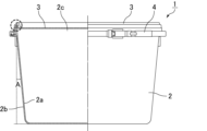
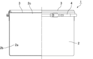
- FIG. 1 is a schematic diagram showing an example of a container according to the present disclosure.
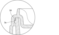
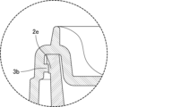
- FIG. 2 is a partial enlarged view of the container of FIG. 1 .
- FIG. 2 is a schematic diagram of a clamp provided on the container of FIG. 1 .
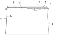
- FIG. 13 is a schematic diagram showing a modified example of the container of the present disclosure.
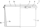
- FIG. 13 is a schematic diagram showing a modified example of the container of the present disclosure.
- FIG. 2 is a partial enlarged view of a variation of the container of the present disclosure.
- FIG. 13 is a schematic diagram showing a modified example of the container of the present disclosure.
- the inventors have studied polytetrafluoroethylene and found that polytetrafluoroethylene, which is useful as a binder for electrochemical devices such as batteries, tends to fibrillate more easily than ordinary polytetrafluoroethylene when stored or transported in a container. In applications where large amounts of polytetrafluoroethylene are used, partial fibrillation does not pose a major problem, but when used as a binder for electrochemical devices, the amount used is small and the impact of fibrillation is significant, so there is a strong need to suppress fibrillation.
- the inventors then conducted further research and discovered that fibrillation of the filled polytetrafluoroethylene can be suppressed if the container has a cylindrical inner wall with a forward or reverse taper, leading to the first disclosure of the present invention.
- the inventors also discovered that fibrillation of the filled polytetrafluoroethylene can be suppressed by setting the mass of the polytetrafluoroethylene filled in the container to 10 kg or less, leading to the second disclosure of the present invention.
- the upper limit of the internal volume of the container of the first disclosure is preferably 150 L or less, more preferably 120 L or less, even more preferably 100 L or less, and even more preferably 80 L or less.
- the lower limit is not particularly limited, but is preferably 5 L or more, more preferably 10 L or more, and even more preferably 20 L.
- the container 1 comprises a body 2, a lid 3, and a clamp 4.
- the main body 2 is a cylindrical member with a tapered inner wall 2a and outer wall 2b on the side, and PTFE is filled in from the opening 2c on the top surface. After filling with PTFE, the lid 3 is attached to the opening 2c of the main body 2 and fixed with a clamp 4, sealing the inside of the main body 2.
- the lid 3 is a circular member configured to cover the opening 2c and side of the main body 2. As shown in FIG. 2, a stepped step 3a is provided on the inside of the lid 3 where it contacts the outer wall 2b, and a protrusion 2d is provided on the outside of the opening 2c of the main body 2. The lid 3 is attached to the opening 2c with the step 3a and the protrusion 2d meshing with each other. This improves the airtightness of the inside of the main body 2.
- the clamp 4 is a ring-shaped member for fixing the lid 3 to the main body 2. As shown in FIG. 3, the clamp 4 is in an open state before installation, and after installation, the clamp 4 is closed and tightened by the attachment portion 4a to fix the lid 3 to the main body 2. This improves the airtightness of the inside of the main body 2.
- the container 1 has the above-mentioned configuration, which provides extremely high airtightness inside the main body 2, making it possible to store PTFE with a low moisture content.
- the difference between the upper inner diameter and the lower inner diameter of the main body 2 is preferably 5 mm or more, more preferably 10 mm or more, even more preferably 15 mm or more, and particularly preferably 20 mm or more, and is preferably 100 mm or less, more preferably 80 mm or less, even more preferably 60 mm or less, and particularly preferably 50 mm or less.
- the upper surface inner diameter is preferably 250 mm or more, more preferably 300 mm or more, even more preferably 350 mm or more, and particularly preferably 400 mm or more, and is preferably 800 mm or less, more preferably 700 mm or less, and even more preferably 600 mm or less.
- the lower surface inner diameter is preferably 200 mm or more, more preferably 250 mm or more, even more preferably 300 mm or more, and particularly preferably 350 mm or more, and is preferably 750 mm or less, more preferably 650 mm or less, even more preferably 600 mm or less, and particularly preferably 550 mm or less.
- the taper angle of the inner wall 2a is preferably 0.5° or more, more preferably 1° or more, even more preferably 1.5° or more, and particularly preferably 2° or more, and is preferably 10° or less, more preferably 9° or less, even more preferably 8° or less, even more preferably 7° or less, even more preferably 6° or less, and particularly preferably 5° or less.
- the suitable range of the taper angle of the outer wall 2b is the same as that of the inner wall 2a.
- the taper angle means the inclination angle of the wall surface with respect to the normal line (see "taper angle A" in FIG. 1).
- the taper ratio of container 1 is preferably 0.01 or more, more preferably 0.02 or more, even more preferably 0.03 or more, even more preferably 0.04 or more, and particularly preferably 0.05 or more, and is preferably 0.20 or less, more preferably 0.19 or less, even more preferably 0.18 or less, even more preferably 0.17 or less, even more preferably 0.16 or less, and particularly preferably 0.15 or less.
- the taper ratio is a value defined by
- the height of the main body 2 is preferably 200 mm or more, more preferably 250 mm or more, and even more preferably 300 mm or more, and is preferably 500 mm or less, more preferably 450 mm or less, and even more preferably 400 mm or less.
- the material of the container 1 (particularly the body 2 and the lid 3 which come into contact with the PTFE) is preferably polypropylene which contains substantially no plasticizer, thereby preventing impurities from being mixed into the PTFE.
- substantially free of plasticizer means that the content of plasticizer relative to polypropylene is 1.0% by mass or less.
- the surface roughness of the inner wall 2a is preferably 1.00 ⁇ m or less. This prevents fibrillation of the PTFE due to contact with the inner wall 2a.
- the lower limit is not particularly limited, but is usually about 0.20 ⁇ m.
- the above surface roughness is a value calculated by observing the surface at a magnification of 5x using a Keyence VK-X1000 series shape analysis laser microscope to obtain an observed image, measuring the arithmetic mean roughness of the obtained image at a distance of 2.5 mm using an analysis application provided with the device, and similarly taking images of a total of three locations, measuring the arithmetic mean roughness, and calculating the average value of these values.
- the container of the first disclosure is not limited to the above-mentioned form and may have other forms.
- the inner wall 2a and the outer wall 2b of the side surface may be reverse tapered.
- the inner wall 2a of the side surface may be forward tapered, and the outer wall 2b may be non-tapered (linear along the normal line).
- the configuration may be the opposite of that shown in Figure 2, i.e., a protrusion 3b is provided on the portion of the lid 3 that contacts the outer wall 2b on the inside, and a stair-like step 2e is provided on the outside of the opening 2c of the main body 2, and the lid 3 may be attached to the opening 2c with the protrusion 3b and the step 2e meshing with each other.
- the second disclosure is a container for filling with polytetrafluoroethylene, in which the mass of the polytetrafluoroethylene filled is 10 kg or less.
- the mass of PTFE filled is 10 kg or less, so that the force generated by its own weight is less likely to be applied to the PTFE powder, making it less likely to be compacted, thereby suppressing fibrillation.
- the container of the second disclosure is preferably filled with PTFE powder having a low apparent density, which makes it difficult for the force generated by its own weight to be applied to the PTFE powder, making it difficult for it to be compacted, thereby suppressing fibrillation.
- the mass of PTFE to be filled is preferably 8 kg or less, more preferably 6 kg or less, and even more preferably 5 kg or less. There is no particular lower limit, but it is usually 1 kg or more.
- the upper limit of the internal volume of the container of the second disclosure is preferably 75 L or less, more preferably 60 L or less, even more preferably 50 L or less, and even more preferably 40 L or less.
- the lower limit is not particularly limited, but is preferably 5 L or more, and more preferably 10 L or more.
- the container of the second disclosure may have a cylindrical inner side wall with a forward or reverse taper, or may have a cylindrical inner side wall with no tapering (straight line along the normal line).
- the inner side wall is cylindrical with a forward or reverse taper.
- containers having cylindrical inner side walls with a forward or reverse taper include those having the same configuration as the container of the first disclosure (configurations shown in Figures 1 to 6).
- containers having cylindrical inner side walls with no tapering (straight line along the normal line) include the configuration shown in Figure 7.
- the first and second containers of the present disclosure will be collectively referred to as the containers of the present disclosure.
- the container of the present disclosure may be filled with a moisture absorbent to maintain a dry state inside the container.
- a moisture absorbent include silica gel, calcium oxide, calcium chloride, etc., with silica gel and calcium oxide being preferred, and silica gel being more preferred.
- the moisture absorbent may be in the form of granules or sheets. It may be used in a packaging material or in a bare state. It may be placed on the PTFE filled in the container, or may be placed at a location on the inner surface of the container, such as the back side of the lid.
- PTFE can be stored without temperature control, which has the advantage of reducing the burden on the container during storage.
- PTFE can be stored at room temperature (15 to 30° C. (preferably 25 to 30° C.)).
- the above-mentioned PTFE can be suitably used as a binder for electrochemical devices.
- electrochemical devices include lithium ion secondary batteries, lithium ion capacitors, capacitors (hybrid capacitors, electric double layer capacitors), radical batteries, solar cells (particularly dye-sensitized solar cells), lithium ion primary batteries, fuel cells, various electrochemical sensors, electrochromic elements, electrochemical switching elements, aluminum electrolytic capacitors, and tantalum electrolytic capacitors.
- the binder may be an electrode binder or a solid electrolyte binder.
- the above PTFE when used as a binder for electrochemical devices, the above PTFE may be used alone or in a mixture with other materials (e.g., polymers other than PTFE).
- the PTFE is preferably in the form of a powder.
- the extrusion pressure at a reduction ratio (RR) of 100 is 5 MPa or more and/or that it is stretchable, and it is more preferable that the extrusion pressure at a RR of 100 is 5 MPa or more and that it is stretchable.
- the above-mentioned PTFE preferably has an extrusion pressure of 5 MPa or more at a reduction ratio (RR) of 100, and from the viewpoint of improving the handling property, binding strength, and flexibility of the electrodes, etc., it is more preferable that the extrusion pressure is 10 MPa or more, even more preferable that the extrusion pressure is 12 MPa or more, even more preferable that the extrusion pressure is 13 MPa or more, and particularly preferable that the extrusion pressure is 15 MPa or more.
- RR reduction ratio
- the extrusion pressure at RR100 is preferably 50 MPa or less, more preferably 40 MPa or less, even more preferably 35 MPa or less, even more preferably 30 MPa or less, even more preferably 25 MPa or less, and particularly preferably 20 MPa or less.
- the above-mentioned PTFE preferably has an extrusion pressure of 10 Pa or more at RR300, more preferably 15 MPa or more, even more preferably 20 MPa or more, even more preferably 25 MPa or more, and particularly preferably 30 MPa or more.
- the extrusion pressure at RR300 is preferably 45 MPa or less, and more preferably 40 MPa or less.
- the extrusion pressure at RR100 is measured by the following method. 50 g of PTFE powder and 10.25 g of hydrocarbon oil (trade name: Isopar E, manufactured by ExxonMobil) as an extrusion aid are mixed in a polyethylene container for 3 minutes. At room temperature (25 ⁇ 2°C), the above mixture is filled into the cylinder of an extruder, and a load of 0.47 MPa is applied to the piston inserted into the cylinder and held for 1 minute. Then, the mixture is extruded from the orifice at a ram speed of 18 mm/min. The ratio of the cross-sectional area of the cylinder to the cross-sectional area of the orifice (reduction ratio) is 100. In the latter half of the extrusion operation, the load (N) when the pressure reaches equilibrium is divided by the cross-sectional area of the cylinder to obtain the extrusion pressure (MPa).
- hydrocarbon oil trade name: Isopar E, manufactured by ExxonMobil
- the extrusion pressure in RR300 is measured by the following method. 50 g of PTFE powder and 11.00 g of hydrocarbon oil (trade name: Isopar E, manufactured by ExxonMobil) as an extrusion aid are mixed in a polyethylene container for 3 minutes. At room temperature (25 ⁇ 2°C), the above mixture is filled into the cylinder of an extruder, and a load of 0.47 MPa is applied to the piston inserted into the cylinder and held for 1 minute. Then, the mixture is extruded from the orifice at a ram speed of 18 mm/min. The ratio of the cross-sectional area of the cylinder to the cross-sectional area of the orifice (reduction ratio) is 300. In the latter half of the extrusion operation, the load (N) when the pressure reaches equilibrium is divided by the cross-sectional area of the cylinder to obtain the extrusion pressure (MPa).
- hydrocarbon oil trade name: Isopar E, manufactured by ExxonMobil
- the PTFE may be either expandable or non-expandable, but is preferably expandable.
- Being stretchable means that a stretched body can be obtained in the following stretching test.
- the bead obtained by the above paste extrusion at RR100 is dried at 230° C. for 30 minutes to remove the lubricant.
- the dried bead is cut to an appropriate length, placed in an oven heated to 300° C., and stretched in the oven at a stretching speed of 1000%/sec.
- the PTFE is preferably stretchable up to 25 times in terms of improving the handling properties, binding strength, and flexibility of the electrode and the like. Whether or not the film can be stretched 25 times can be confirmed by the following stretching test.
- the bead obtained by the above paste extrusion at RR100 is dried at 230°C for 30 minutes to remove the lubricant.
- the dried bead is cut to an appropriate length and placed in an oven heated to 300°C. In the oven, it is stretched at a stretching speed of 1000%/sec until it becomes 25 times the bead length before the stretching test. If it does not break during stretching, it is judged that it can be stretched to 25 times.
- the PTFE is substantially free of moisture. This is advantageous in terms of the production process because it allows a wide range of electrode active materials to be combined with the PTFE.
- “Substantially free of moisture” means that the moisture content of the PTFE is 0.050% by mass or less.
- the moisture content is preferably 0.040% by mass or less, more preferably 0.020% by mass or less, even more preferably 0.010% by mass or less, even more preferably 0.005% by mass or less, and particularly preferably 0.002% by mass or less.
- the water content is measured by the following method.
- the mass of the PTFE powder is measured before and after heating at 150° C. for 2 hours, and the mass is calculated according to the following formula.
- Moisture content (mass%) [(mass (g) of PTFE powder before heating) ⁇ (mass (g) of PTFE powder after heating)]/(mass (g) of PTFE powder before heating) ⁇ 100
- the apparent density of the PTFE is preferably 0.40 g/ml or more, more preferably 0.43 g/ml or more, even more preferably 0.45 g/ml or more, and even more preferably 0.48 g/ml or more.
- the upper limit is not particularly limited, but may be 0.60 g/ml.
- the apparent density is measured in accordance with JIS K6892.
- the above PTFE preferably has an apparent density of less than 0.50 g/ml, more preferably 0.48 g/ml or less, even more preferably 0.45 g/ml or less, even more preferably 0.40 g/ml or less, and particularly preferably less than 0.40 g/ml, and preferably 0.20 g/ml or more, more preferably 0.25 g/ml or more, even more preferably 0.30 g/ml or more, and particularly preferably 0.35 g/ml or more.
- the above-mentioned PTFE has a powder particle size of preferably 300 ⁇ m or more, more preferably 450 ⁇ m or more, even more preferably 500 ⁇ m or more, even more preferably 550 ⁇ m or more, and particularly preferably 600 ⁇ m or more, and is preferably 1000 ⁇ m or less, more preferably 900 ⁇ m or less, even more preferably 800 ⁇ m or less, and particularly preferably 700 ⁇ m or less.
- the powder particle size is determined by a laser diffraction method. The dry method is performed using a HELOS & ROD OS system (product name, manufactured by SYMPATEC).
- the powder to be measured is dispersed with compressed air at a dispersion pressure of 2 bar, and the measurement sensor detects the shadow of the powder to be measured projected by a laser to calculate the particle size distribution of the powder to be measured, and the average particle size (50% cumulative particle size) d50 is determined on a volume basis.
- the above PTFE has a powder particle size of preferably less than 600 ⁇ m, more preferably 400 ⁇ m or less, even more preferably 300 ⁇ m or less, and particularly preferably less than 300 ⁇ m, and is preferably 10 ⁇ m or more, more preferably 50 ⁇ m or more, and particularly preferably 100 ⁇ m or more, in order to suppress fibrillation.
- the above-mentioned PTFE preferably has a standard specific gravity (SSG) of 2.200 or less, more preferably 2.180 or less, even more preferably 2.170 or less, even more preferably 2.160 or less, even more preferably 2.150 or less, and even more preferably 2.145 or less, in terms of improving handleability, extensibility, binding strength, and flexibility of electrodes, etc.
- SSG standard specific gravity
- the SSG is also preferably 2.130 or greater.
- the SSG is measured by a water displacement method according to ASTM D 792 using a sample molded according to ASTM D 4895.
- the average primary particle size is preferably 350 nm or less, more preferably 330 nm or less, even more preferably 320 nm or less, even more preferably 300 nm or less, even more preferably 280 nm or less, and particularly preferably 250 nm or less, and is preferably 100 nm or more, more preferably 150 nm or more, even more preferably 170 nm or more, and particularly preferably 200 nm or more.
- the average primary particle size is measured by the following method.
- the PTFE aqueous dispersion is diluted with water until the solid content concentration is 0.15% by mass, and the transmittance of the 550 nm projected light to the unit length of the obtained diluted latex and the number-based length average particle diameter determined by measuring a specific direction using a transmission electron microscope photograph are measured to prepare a calibration curve. Using this calibration curve, the number-average particle diameter is determined from the measured transmittance of the 550 nm projected light of each sample, and is taken as the average primary particle diameter.
- the PTFE may have an average aspect ratio of 2.0 or less, preferably 1.8 or less, more preferably 1.7 or less, even more preferably 1.6 or less, even more preferably 1.5 or less, even more preferably 1.4 or less, even more preferably 1.3 or less, particularly preferably 1.2 or less, and most preferably 1.1 or less.
- the average aspect ratio may also be 1.0 or more. The above-mentioned average aspect ratio is determined by observing PTFE powder or an aqueous PTFE dispersion diluted to a solids concentration of approximately 1% by mass with a scanning electron microscope (SEM), processing the images of 200 or more particles randomly selected, and averaging the ratio of the long axis to the short axis.
- SEM scanning electron microscope
- the PTFE preferably has non-melt secondary processability.
- the non-melt secondary processability means that the melt flow rate cannot be measured at a temperature higher than the melting point in accordance with ASTM D-1238 and D-2116, in other words, that the PTFE does not flow easily even in the melting temperature range.
- the above-mentioned PTFE may be a homopolymer of tetrafluoroethylene (TFE), or may be a modified PTFE that contains a polymerization unit based on TFE (TFE unit) and a polymerization unit based on modified monomer (hereinafter also referred to as "modified monomer unit").
- TFE unit polymerization unit based on TFE
- modified monomer unit modified monomer unit
- the above-mentioned modified PTFE may contain 99.0 mass% or more of TFE unit and 1.0 mass% or less of modified monomer unit.
- the above-mentioned modified PTFE may be composed of only TFE unit and modified monomer unit.
- the PTFE is preferably the modified PTFE, which improves the binding strength and flexibility of the electrode, etc.
- a TFE homopolymer is preferable, which improves handling properties.
- the modified PTFE preferably has a modified monomer unit content of 0.00001 to 1.0% by mass relative to the total polymerized units, in terms of improving stretchability, binding strength, and flexibility of electrodes, etc.
- the lower limit of the modified monomer unit content is more preferably 0.0001% by mass, more preferably 0.001% by mass, even more preferably 0.005% by mass, and particularly preferably 0.010% by mass.
- the upper limit of the modified monomer unit content is preferably 0.90% by mass, more preferably 0.80% by mass, more preferably 0.50% by mass, even more preferably 0.40% by mass, even more preferably 0.30% by mass, even more preferably 0.20% by mass, even more preferably 0.15% by mass, even more preferably 0.10% by mass, even more preferably 0.08% by mass, especially preferably 0.05% by mass, and most preferably 0.03% by mass.
- the modified monomer unit means a portion of the molecular structure of PTFE that is derived from a modified monomer.
- the content of each of the above-mentioned polymerized units can be calculated by appropriately combining NMR, FT-IR, elemental analysis, and X-ray fluorescence analysis depending on the type of monomer.
- the modified monomer is not particularly limited as long as it can be copolymerized with TFE, and examples thereof include perfluoroolefins such as hexafluoropropylene [HFP]; hydrogen-containing fluoroolefins such as trifluoroethylene and vinylidene fluoride [VDF]; perhaloolefins such as chlorotrifluoroethylene; perfluorovinyl ethers; perfluoroallyl ethers; (perfluoroalkyl)ethylenes, ethylenes, etc.
- the modified monomers used may be one type or multiple types.
- Rf represents a perfluoro organic group.
- the "perfluoro organic group” refers to an organic group in which all hydrogen atoms bonded to carbon atoms are replaced with fluorine atoms.
- the perfluoro organic group may have an ether oxygen.
- the above-mentioned perfluorovinyl ether is, for example, perfluoro(alkyl vinyl ether) [PAVE], in which Rf is a perfluoroalkyl group having 1 to 10 carbon atoms in the above-mentioned general formula (A).
- the number of carbon atoms in the above-mentioned perfluoroalkyl group is preferably 1 to 5.
- Examples of the perfluoroalkyl group in the above PAVE include a perfluoromethyl group, a perfluoroethyl group, a perfluoropropyl group, a perfluorobutyl group, a perfluoropentyl group, and a perfluorohexyl group.
- the above-mentioned perfluorovinyl ether further includes those in which Rf in the above-mentioned general formula (A) is a perfluoro(alkoxyalkyl) group having 4 to 9 carbon atoms, and those in which Rf is the following formula:
- Rf is a group represented by the following formula:
- n is an integer from 1 to 4.
- the (perfluoroalkyl)ethylene (PFAE) is not particularly limited, and examples include (perfluorobutyl)ethylene (PFBE) and (perfluorohexyl)ethylene.
- the above Rf 1 is preferably a perfluoroalkyl group having 1 to 10 carbon atoms or a perfluoroalkoxyalkyl group having 1 to 10 carbon atoms.
- the above-mentioned perfluoroallyl ether is preferably at least one selected from the group consisting of CF 2 ⁇ CF-CF 2 -O-CF 3 , CF 2 ⁇ CF-CF 2 -O-C 2 F 5 , CF 2 ⁇ CF-CF 2 -O-C 3 F 7 , and CF 2 ⁇ CF-CF 2 -O-C 4 F 9 , more preferably at least one selected from the group consisting of CF 2 ⁇ CF-CF 2 -O-C 2 F 5 , CF 2 ⁇ CF-CF 2 -O-C 3 F 7 , and CF 2 ⁇ CF-CF 2 -O-C 4 F 9 , and even more preferably CF 2 ⁇ CF-CF 2 -O-CF 2 CF 2 CF 3 .
- the modified monomer at least one selected from the group consisting of PAVE and HFP is preferred, in terms of improving the stretchability, binding strength, and flexibility of the electrodes, etc., and at least one selected from the group consisting of perfluoro(methyl vinyl ether) (PMVE) and HFP is more preferred.
- the other modified monomer at least one selected from the group consisting of VDF, HFP, CTFE and PAVE is preferable, and at least one selected from the group consisting of VDF, HFP and CTFE is more preferable, in that a composite sheet having excellent strength can be formed.
- the PTFE contains TFE units, VDF units and HFP units, and the total amount of the VDF units and the HFP units is 1.0 mass % or less based on the total polymerized units.
- the above PTFE preferably has a core-shell structure in terms of ease of handling.
- An example of PTFE having a core-shell structure is modified PTFE, which contains a core of high molecular weight PTFE and a shell of lower molecular weight PTFE or modified PTFE in the particle.
- modified PTFE is the PTFE described in JP-A-2005-527652.
- the PTFE preferably has an endothermic peak temperature of 320° C. or higher, more preferably 325° C. or higher, even more preferably 330° C. or higher, even more preferably 335° C. or higher, even more preferably 340° C. or higher, even more preferably 342° C. or higher, and particularly preferably 344° C. or higher, in that a composite sheet having excellent strength can be formed.
- the endothermic peak temperature is also preferably 350° C. or lower.
- the endothermic peak temperature is a temperature corresponding to a minimum point in a heat of fusion curve obtained by performing differential scanning calorimetry (DSC) at a heating rate of 10° C./min on a fluororesin that has not been heated to a temperature of 300° C. or higher.
- DSC differential scanning calorimetry
- the above PTFE preferably has one or more endothermic peaks in the range of 333 to 347°C in the heat of fusion curve when heated at a rate of 10°C/min using a differential scanning calorimeter [DSC], and the heat of fusion at 290 to 350°C calculated from the heat of fusion curve is 62 mJ/mg or more.
- the PTFE preferably has a number average molecular weight (Mn) of 3.0 ⁇ 10 6 or more, more preferably 3.2 ⁇ 10 6 or more, even more preferably 3.5 ⁇ 10 6 or more, even more preferably 3.7 ⁇ 10 6 or more, and particularly preferably 4.0 ⁇ 10 6 or more, in terms of being able to form a composite sheet having excellent strength.
- Mn number average molecular weight
- the number average molecular weight is also preferably 7.0 ⁇ 10 6 or less, more preferably 6.5 ⁇ 10 6 or less, even more preferably 6.0 ⁇ 10 6 or less, even more preferably 5.5 ⁇ 10 6 or less , and particularly preferably 5.0 ⁇ 10 6 or less.
- the number average molecular weight is a molecular weight calculated from the heat of crystallization estimated by measuring the temperature drop of a melted fluororesin using a differential scanning calorimeter (DSC) according to the method described in the following document. The measurement is carried out five times, and the average value of the three values excluding the maximum and minimum values is used.
- DSC differential scanning calorimeter
- the PTFE preferably does not substantially contain fluorine-containing compounds having a molecular weight of not more than 1000.
- substantially free of fluorine-containing compounds means that the amount of the fluorine-containing compounds is 25 ppb by mass or less relative to the PTFE.
- the amount of the fluorine-containing compound is more preferably less than 25 mass ppb, even more preferably 10 mass ppb or less, even more preferably 5 mass ppb or less, even more preferably 3 mass ppb or less, and particularly preferably 1 mass ppb or less.
- the lower limit is not particularly limited, and may be an amount below the detection limit.
- the amount of the fluorine-containing compound having a molecular weight of 1,000 or less is measured by the following method. Weigh out 1 g of the sample, add 10 g (12.6 ml) of methanol, and perform ultrasonic treatment for 60 minutes to obtain an extract. The obtained extract is appropriately concentrated with nitrogen purge, and the fluorine-containing compounds in the concentrated extract are measured by LC/MS/MS. Molecular weight information is extracted from the obtained LC/MS spectrum, and the agreement with the structural formula of the candidate fluorine-containing compound is confirmed. Prepare aqueous solutions with 5 or more levels of content of the standard substance, perform LC/MS analysis of the aqueous solutions with each content, plot the relationship between the content and the area area for that content, and draw a calibration curve. Using the above calibration curve, the area area of the LC/MS chromatogram of the fluorine-containing compound in the extract is converted to the content of the fluorine-containing compound. The lower detection limit in this measurement method is 10 ppb by mass.
- the amount of the fluorine-containing compound having a molecular weight of 1,000 or less can also be measured by the following method. Weigh out 1 g of the sample, add 10 g (12.6 ml) of methanol, perform ultrasonic treatment at 60 ° C for 2 hours, and leave at room temperature, then remove the solid content to obtain an extract. The obtained extract is appropriately concentrated with nitrogen purge, and the fluorine-containing compounds in the concentrated extract are measured by LC / MS / MS. From the obtained LC / MS spectrum, molecular weight information is extracted and confirmed to match the structural formula of the candidate fluorine-containing compound.
- Examples of the fluorine-containing compound having a molecular weight of 1000 or less include a fluorine-containing compound having a hydrophilic group and a molecular weight of 1000 g/mol or less.
- the molecular weight of the fluorine-containing compound is preferably 800 or less, and more preferably 500 or less.
- Polymer particles obtained by polymerization in the presence of a fluorine-containing surfactant usually contain a fluorine-containing surfactant in addition to PTFE.
- the fluorine-containing surfactant is one that is used during polymerization.
- the fluorine-containing compound having a molecular weight of 1,000 or less may be a compound that has not been added during polymerization, for example, a compound that is generated as a by-product during polymerization.
- the fluorine-containing compound having a molecular weight of 1000 or less contains an anionic moiety and a cationic moiety, it means a compound containing fluorine in which the molecular weight of the anionic moiety is 1000 or less.
- the fluorine-containing compound having a molecular weight of 1000 or less does not include PTFE.
- the hydrophilic group may be, for example, -COOM, -SO 2 M, or -SO 3 M, and examples of such anionic groups include -COOM and -SO 3 M (in each formula, M is H, a metal atom, NR 1 4 , an imidazolium which may have a substituent, a pyridinium which may have a substituent, or a phosphonium which may have a substituent, and R 1 is H or an organic group).
- a surfactant containing fluorine in which the molecular weight of the anionic portion is 1000 or less can also be used.
- the "anionic portion” refers to the portion of the fluorine-containing surfactant excluding the cation. For example, in the case of F(CF 2 ) n1 COOM, it is the portion "F(CF 2 ) n1 COO".
- the anionic fluorine-containing surfactant may be a compound represented by the following general formula (N 0 ): X n0 - Rf n0 - Y 0 (N 0 ) (In the formula, X n0 is H, Cl or F.
- Rf n0 is a linear, branched or cyclic alkylene group having 3 to 20 carbon atoms in which some or all of the H's are substituted with F, and the alkylene group may contain one or more ether bonds, and some of the H's may be substituted with Cl.
- Y 0 is an anionic group. The anionic group of Y 0 may be -COOM, -SO 2 M or -SO 3 M, and may be -COOM or -SO 3 M.
- M is H, a metal atom, NR 1 4 , an imidazolium which may have a substituent, a pyridinium which may have a substituent, or a phosphonium which may have a substituent, and R 1 is H or an organic group.
- the metal atom includes alkali metals (Group 1) and alkaline earth metals (Group 2), such as Na, K, or Li.
- R 1 may be H or a C 1-10 organic group, may be H or a C 1-4 organic group, or may be H or a C 1-4 alkyl group.
- M may be H, a metal atom or NR 1 4 , which may be H, an alkali metal (group 1), an alkaline earth metal (group 2) or NR 1 4 , which may be H, Na, K, Li or NH 4 .
- Rf n0 may be one in which 50% or more of H is substituted with fluorine.
- the above-mentioned fluorine-containing surfactant may be one type of fluorine-containing surfactant or a mixture containing two or more types of fluorine-containing surfactants.
- fluorine-containing surfactant examples include compounds represented by the following formula:
- the fluorine-containing surfactant may be a mixture of these compounds.
- M may be H, a metal atom or NR 1 4 , which may be H, an alkali metal (group 1), an alkaline earth metal (group 2) or NR 1 4 , which may be H, Na, K, Li or NH 4 .
- R 1 may be H or a C 1-10 organic group, may be H or a C 1-4 organic group, may be H or a C 1-4 alkyl group.
- substantially free of any of the fluorine-containing compounds represented by the above formulas means that the amount of the fluorine-containing compounds is 25 ppb by mass or less relative to the PTFE.
- the amount of the fluorine-containing compound is preferably less than 25 ppb by mass, more preferably 10 ppb by mass or less, even more preferably 5 ppb by mass or less, even more preferably 3 ppb by mass or less, and particularly preferably 1 ppb by mass or less.
- the lower limit is not particularly limited, and may be an amount below the detection limit.
- the PTFE has the following general formula: [C n-1 F 2n-1 COO - ]M + (wherein n is an integer of 9 to 14, preferably an integer of 9 to 12, and M + represents a cation.) This makes it possible to suppress gas generation and deterioration of battery characteristics, and also to improve sheet strength.
- M constituting the cation M + is the same as M described above.
- “Substantially free of the fluorine-containing compound represented by the above formula” means that the amount of the fluorine-containing compound is 25 ppb by mass or less relative to the PTFE.
- the amount of the fluorine-containing compound is preferably less than 25 ppb by mass, more preferably 10 ppb by mass or less, even more preferably 5 ppb by mass or less, even more preferably 3 ppb by mass or less, and particularly preferably 1 ppb by mass or less.
- the lower limit is not particularly limited, and may be an amount below the detection limit.
- ⁇ RR100 Extrusion Pressure (Extrusion Pressure at Reduction Ratio 100)> 50 g of PTFE powder and 10.25 g of hydrocarbon oil (trade name: Isopar E, manufactured by ExxonMobil) as an extrusion aid were mixed in a polyethylene container for 3 minutes. At room temperature (25 ⁇ 2°C), the above mixture was filled into the cylinder of an extruder, and a load of 0.47 MPa was applied to the piston inserted into the cylinder and held for 1 minute. The mixture was then extruded from the orifice at a ram speed of 51 cm/min. The ratio of the cross-sectional area of the cylinder to the cross-sectional area of the orifice was 100. In the latter half of the extrusion operation, the load (N) when the pressure reached equilibrium was divided by the cross-sectional area of the cylinder to obtain the extrusion pressure (MPa).
- the stretching test was carried out in accordance with the method described in JP-A-2002-201217 as follows.
- the bead obtained by the above paste extrusion was heated at 230°C for 30 minutes to remove the lubricant from the bead.
- the bead (extrudate) was then cut to the appropriate length, clamped at each end with a clamp distance of 1.5 inches (38 mm) apart, and heated to 300°C in an air circulating oven.
- the clamps were then separated at a desired speed (stretch rate) until a separation distance corresponding to the desired stretch (total stretch) was achieved, and a stretch test (stretch test) was performed.
- the stretch method essentially followed the method disclosed in U.S. Pat. No.
- Stretch is the increase in length due to stretching, usually expressed as a percentage of the original length. In the stretch method, the stretch rate was 1000%/sec, and the total stretch was 2400%. In the above stretch test, those that did not break during stretching were considered stretchable, and those that broke during stretching were considered unstretchable.
- ⁇ Powder particle size> The measurement was performed by a laser diffraction method. The measurement was performed in a dry state using a HELOS & ROD OS system (product name, manufactured by SYMPATEC). The powder to be measured was dispersed by compressed air with a dispersion pressure of 2 bar, and the shadow of the powder to be measured projected by a laser was sensed by the measurement sensor unit, whereby the particle size distribution of the powder to be measured was calculated, and the average particle size (50% cumulative particle size) d50 value was obtained on a volume basis. The powder particle size was set to be equal to the particle size corresponding to 50% of the cumulative particle size distribution.
- Moisture content (mass%) [(mass (g) of PTFE powder before heating) ⁇ (mass (g) of PTFE powder after heating)]/(mass (g) of PTFE powder before heating) ⁇ 100
- Desorption rate (W2/W1) x 100 (%) (Wherein, W1 is the total mass (g) of the mixture before testing, and W2 is the mass (g) of the screened mixture.) Excellent: Detachment rate less than 1% Good: Detachment rate between 1% and 2% Acceptable: Detachment rate between 2% and 3% Poor: Detachment rate 3% or more
- Experimental Example 1 15 kg of PTFE powder was placed in a 60 L plastic container (material: polypropylene, no plasticizer (content relative to polypropylene: 0% by mass), surface roughness of the inner wall: 0.23 ⁇ m) with a forward taper angle of 3.0° and a difference between the upper and lower inner diameters of 30 mm, and stored for half a year in an atmosphere at 25° C.
- the clumping tendency of the stored PTFE powder was 0.4% by mass, and the moisture content was 0.002% by mass.
- a positive electrode mixture was prepared by the above-mentioned method, and the ease of bonding was evaluated. The detachment rate was 0.4 mass %, and the ease of bonding was excellent.
- the PTFE powder used was the PTFE powder described in Example 1 of WO 2023/054709, and had a standard specific gravity (SSG) of 2.159, an RR100 extrusion pressure of 15.1 MPa, extensible, a powder particle size of 540 ⁇ m, an apparent density of 0.48 g/ml, and a moisture content of 0.002% by mass.
- SSG standard specific gravity
- the container has a lid attached to the opening and a clamp for fixing the container, and has the same shape as in Experimental Example 1.
- the PTFE powder filled in the container is the PTFE powder described in Example 2 of International Publication No. 2023/054707, and is stored for half a year in an atmosphere at 25 ° C. in the same manner as in Experimental Example 1, except that the standard specific gravity (SSG) is 2.145, the RR100 extrusion pressure is 17.4 MPa, it is stretchable, the powder particle size is 540 ⁇ m, the apparent density is 0.43 g / ml, and the moisture content is 0.000 mass%.
- the clumping property of the stored PTFE powder was 0.3 mass%, and the moisture content was 0.001 mass%.
- the adhesiveness of the positive electrode mixture was evaluated, and the detachment rate was 0.5% by mass, indicating that the adhesiveness was excellent.
- Experimental Example 3 The container was stored for half a year in an atmosphere at 10° C. in the same manner as in Experimental Example 2, except that the step on the lid and the protrusion on the container body were interlocked and silica gel was used as a moisture absorbent for the container.
- the clumping property of the stored PTFE powder was 0.2% by mass, and the moisture content was 0.000% by mass.
- the binding ease of the positive electrode mixture was evaluated, and the detachment rate was 0.5% by mass, indicating that the binding ease was excellent.
- the PTFE powder to be filled in the container is the PTFE powder described in Example 18 of International Publication No. 2023/054723, and was stored for half a year in an atmosphere at 25 ° C. in the same manner as in Experimental Example 2, except that the standard specific gravity (SSG) was 2.170, the RR100 extrusion pressure was 5.6 MPa, stretching was not possible, the powder particle size was 540 ⁇ m, the apparent density was 0.48 g / ml, and the moisture content was 0.001 mass%.
- the clumping property of the stored PTFE powder was 0.1 mass%, and the moisture content was 0.002 mass%.
- the detachment rate was 0.8 mass%, and the ease of binding was excellent.
- Experimental Example 5 The container was made of plastic (material: polypropylene, no plasticizer (content relative to polypropylene: 0% by mass), surface roughness of the inner wall: 0.23 ⁇ m) with a capacity of 30 L and a forward taper angle of 0°, and the difference between the upper inner diameter and the lower inner diameter was 0 mm. Except for this, 5 kg of PTFE powder was placed in a container, which was stored for half a year in an atmosphere at 25° C., in the same manner as in Experimental Example 1. The clumping property of the stored PTFE powder was 2.5% by mass, and the moisture content was 0.005% by mass. The adhesion ease of the positive electrode mixture was evaluated, and the detachment rate was 2.1% by mass, indicating that the adhesion ease was acceptable.
- plastic material: polypropylene, no plasticizer (content relative to polypropylene: 0% by mass), surface roughness of the inner wall: 0.23 ⁇ m) with a capacity of 30 L and a forward taper angle of
- the PTFE aqueous dispersion obtained by Production Example 1 of International Publication No. 2023/054713 was diluted to a solid content concentration of 8.5% by mass, the liquid temperature was adjusted to 10 ° C., nitric acid was added, and high-speed stirring was performed in a container to cause coagulation and drying at 210 ° C. to obtain PTFE powder.
- the obtained PTFE powder had a standard specific gravity (SSG) of 2.158, an RR100 extrusion pressure of 16.3 MPa, was stretchable, had a powder particle size of 145 ⁇ m, an apparent density of 0.35 g / ml, and a moisture content of 0.002 mass%.
- SSG standard specific gravity
- RR100 extrusion pressure 16.3 MPa
- the obtained PTFE powder was stored for half a year in an atmosphere of 25 ° C. in the same manner as in Experimental Example 5.
- the clumping property of the stored PTFE powder was 1.5 mass%, and the moisture content was 0.005 mass%.
- the detachment rate was 1.3 mass%, and the ease of binding was good.
- Experimental Example 7 A plastic container (material: polypropylene, no plasticizer (content relative to polypropylene: 0% by mass), surface roughness of the inner wall: 0.23 ⁇ m) with a taper angle of 0°, i.e., a difference between the upper inner diameter and the lower inner diameter of 0 mm was used and stored in the same manner as in Experimental Example 1.
- the clumping property of the stored PTFE powder was 5.6% by mass.
- a positive electrode mixture was prepared by the above-mentioned method, and the ease of bonding was evaluated. The detachment rate was 3.6 mass %, and the ease of bonding was poor.
- Container 2 Main body 2a: Inner wall 2b: Outer wall 2c: Opening 2d: Protrusion 2e: Step 3: Lid 3a: Step 3b: Protrusion 4: Clamp 4a: Mounting portion A: Taper angle
Landscapes
- Engineering & Computer Science (AREA)
- Mechanical Engineering (AREA)
- Chemical & Material Sciences (AREA)
- Polymers & Plastics (AREA)
- Chemical Kinetics & Catalysis (AREA)
- Medicinal Chemistry (AREA)
- Health & Medical Sciences (AREA)
- Organic Chemistry (AREA)
- Food Science & Technology (AREA)
- Compositions Of Macromolecular Compounds (AREA)
- Containers Having Bodies Formed In One Piece (AREA)
- Closures For Containers (AREA)
- Addition Polymer Or Copolymer, Post-Treatments, Or Chemical Modifications (AREA)
Abstract
Description
上記上面内径は、250mm以上であることが好ましく、300mm以上であることがより好ましく、350mm以上であることが更に好ましく、400mm以上であることが特に好ましく、また、800mm以下であることが好ましく、700mm以下であることがより好ましく、600mm以下であることが更に好ましい。
上記下面内径は、200mm以上であることが好ましく、250mm以上であることがより好ましく、300mm以上であることが更に好ましく、350mm以上であることが特に好ましく、また、750mm以下であることが好ましく、650mm以下であることがより好ましく、600mm以下であることが更に好ましく、550mm以下であることが特に好ましい。
上記テーパー角度は、法線に対する壁面の傾斜角度を意味する(図1における「テーパー角度A」参照)。
上記テーパー比は、|本体2の上面内径-本体2の下面内径|/本体2の高さで定義される値である。
可塑剤を実質的に含まないとは、ポリプロピレンに対する可塑剤の含有量が1.0質量%以下であることを意味する。
上記表面粗さは、キーエンス社製形状解析レーザー顕微鏡VK-X1000シリーズを用いて倍率5倍で表面を観察し、観察画像を得、装置付属の解析アプリケーションを用いて、得られた画像について2.5mmの距離で算術平均粗さを測定し、同様に合計3か所の画像を撮影し算術平均粗さを測定して、それらの平均値として算出される値である。
例えば、図4で示すように、側面の内壁2a及び外壁2bが逆テーパーであってもよい。
また、図5で示すように、側面の内壁2aが順テーパーで、外壁2bがテーパーしていない形状(法線に沿った直線状)であってもよい。
また、図6で示すように、図2とは逆の形態、すなわち、蓋3の内側の外壁2bと接する部分には突起3bが、本体2の開口部2cの外側には階段状の段差2eが設けられており、蓋3は、突起3bと段差2eとが噛み合った状態で開口部2cに装着されてもよい。
また、第二の本開示の容器は、見掛密度が低いPTFE粉末を充填することが好ましい。それにより、自重によって生じる力がPTFEの粉末に加わりにくくなり、圧密されにくくなるため、フィブリル化を抑制できる。
吸湿剤は、粒状であってもよいし、シート状であってもよい。また、包材に入れて使用してもよいし、むき出しの状態で使用してもよい。また、容器内に充填されたPTFEの上に配置してもよいし、蓋の裏面等の容器内面に設けた設置場所に配置してもよい。
本開示はまた、本開示の容器にPTFEを充填して保管する保管方法にも関する。本開示の保管方法では、常温(15~30℃(好ましくは25~30℃))でPTFEを保管できる。
RR100における押出圧力は、また、加工性が向上する点で、50MPa以下であることが好ましく、40MPa以下であることがより好ましく、35MPa以下であることが更に好ましく、30MPa以下であることが更により好ましく、25MPa以下であることが更により好ましく、20MPa以下であることが特に好ましい。
RR300における押出圧力は、また、加工性が向上する点で、45MPa以下であることが好ましく、40MPa以下であることがより好ましい。
PTFE粉末50gと押出助剤としての炭化水素油(商品名:アイソパーE、エクソンモービル社製)10.25gとをポリエチレン容器内で3分間混合する。室温(25±2℃)で、押出機のシリンダーに上記混合物を充填し、シリンダーに挿入したピストンに0.47MPaの負荷をかけて1分間保持する。次にラム速度18mm/minでオリフィスから押出する。オリフィスの断面積に対するシリンダーの断面積の比(リダクションレシオ)は100である。押出操作の後半において、圧力が平衡状態になったときの荷重(N)をシリンダー断面積で除した値を押出圧力(MPa)とする。
PTFE粉末50gと押出助剤としての炭化水素油(商品名:アイソパーE、エクソンモービル社製)11.00gとをポリエチレン容器内で3分間混合する。室温(25±2℃)で、押出機のシリンダーに上記混合物を充填し、シリンダーに挿入したピストンに0.47MPaの負荷をかけて1分間保持する。次にラム速度18mm/minでオリフィスから押出する。オリフィスの断面積に対するシリンダーの断面積の比(リダクションレシオ)は300である。押出操作の後半において、圧力が平衡状態になったときの荷重(N)をシリンダー断面積で除した値を押出圧力(MPa)とする。
延伸可能であるとは、以下の延伸試験において延伸体が得られることを意味する。
上記のRR100でのペースト押出により得られたビードを230℃で30分間乾燥し、潤滑剤を除去する。乾燥後のビードを適当な長さに切断し、300℃に加熱した炉に入れ、炉内で、延伸速度1000%/秒で延伸する。
25倍に延伸可能であるか否かは、以下の延伸試験により確認することができる。
上記のRR100でのペースト押出により得られたビードを230℃で30分間乾燥し、潤滑剤を除去する。乾燥後のビードを適当な長さに切断し、300℃に加熱した炉に入れる。炉内で、延伸速度1000%/秒で、延伸試験前のビード長さの25倍になるまで延伸する。延伸中に破断しなければ、25倍に延伸可能であると判定する。
上記水分含有量は、0.040質量%以下であることが好ましく、0.020質量%以下であることがより好ましく、0.010質量%以下であることが更に好ましく、0.005質量%以下であることが更により好ましく、0.002質量%以下であることが特に好ましい。
上記水分含有量は、以下の方法により測定する。
PTFE粉末を150℃で2時間加熱した前後の質量を測定し、以下の式に従って算出する。試料を3回取り、それぞれ算出した後、平均を求め、当該平均値を採用する。
水分含有量(質量%)=[(加熱前のPTFE粉末の質量(g))-(加熱後のPTFE粉末の質量(g))]/(加熱前のPTFE粉末の質量(g))×100
上記見掛密度は、JIS K 6892に準拠して測定する。
上記粉体粒径は、レーザー回折法により求める。HELOS&ROD OSシステム(商品名、SYMPATEC社製)を用いて、乾式にて行なう。分散圧力2barの圧縮空気により分散された被測定粉末を、レーザーにより映し出された被測定粉末の影を測定センサー部が感知する事で、被測定粉末の粒度分布を演算し、体積基準にて平均粒子径(50%積算粒子径)d50の値を求めることにより測定する。
上記SSGは、また、2.130以上であることが好ましい。
上記SSGは、ASTM D 4895に準拠して成形されたサンプルを用い、ASTM D 792に準拠した水置換法により測定する。
上記平均一次粒子径は、以下の方法により測定する。
PTFE水性分散液を水で固形分濃度0.15質量%になるまで希釈し、得られた希釈ラテックスの単位長さに対する550nmの投射光の透過率と、透過型電子顕微鏡写真により定方向を測定して決定した数基準長さ平均粒子径とを測定して、検量線を作成する。この検量線を用いて、各試料の550nmの投射光の実測透過率から数平均粒子径を決定し、平均一次粒子径とする。
上記平均アスペクト比は、PTFE粉末、又は、固形分濃度が約1質量%となるように希釈したPTFE水性分散液を走査電子顕微鏡(SEM)で観察し、無作為に抽出した200個以上の粒子について画像処理を行い、その長径と短径の比の平均より求める。
上記PTFEとしては、結着力及び電極等の柔軟性が向上する点で、上記変性PTFEが好ましい。取り扱い性が向上する点では、TFE単独重合体が好ましい。
本明細書において、上記変性モノマー単位とは、PTFEの分子構造の一部分であって変性モノマーに由来する部分を意味する。
CF2=CF-ORf (A)
(式中、Rfは、パーフルオロ有機基を表す。)で表されるパーフルオロ不飽和化合物等が挙げられる。本明細書において、上記「パーフルオロ有機基」とは、炭素原子に結合する水素原子が全てフッ素原子に置換されてなる有機基を意味する。上記パーフルオロ有機基は、エーテル酸素を有していてもよい。
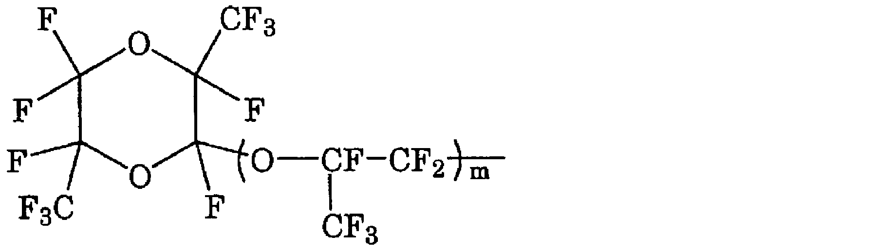

CF2=CF-CF2-ORf1 (B)
(式中、Rf1は、パーフルオロ有機基を表す。)で表されるフルオロモノマーが挙げられる。
耐熱性が向上する点で、上記PTFEがTFE単位、VDF単位及びHFP単位を含み、VDF単位及びHFP単位の合計量が、全重合単位に対し1.0質量%以下であることは、好適な態様の1つである。
上記吸熱ピーク温度は、300℃以上の温度に加熱した履歴がないフッ素樹脂について10℃/分の昇温速度で示差走査熱量測定〔DSC〕を行って得られた融解熱曲線における極小点に対応する温度である。1つの融解ピーク中に極小点が2つ以上ある場合は、それぞれを吸熱ピーク温度とする。
上記数平均分子量は、フッ素樹脂を溶融後に示差走査型熱量計(DSC)の降温測定を行って見積もった結晶化熱から、下記の文献に記載の方法に従って求めた分子量である。測定は5回行い、最大値及び最小値を除いた3つの値の平均値を採用する。
文献:Suwa,T.;Takehisa,M.;Machi,S.,J.Appl.Polym.Sci.vol.17,pp.3253(1973).
上記含フッ素化合物の量は、25質量ppb未満であることがより好ましく、10質量ppb以下であることが更に好ましく、5質量ppb以下であることが更により好ましく、3質量ppb以下であることが更により好ましく、1質量ppb以下が特に好ましい。下限は特に限定されず、検出限界未満の量であってよい。
試料を1g秤量し、メタノールを10g(12.6ml)加え、60分間の超音波処理を行ない、抽出液を得る。得られた抽出液を適宜窒素パージで濃縮し、濃縮後の抽出液中の含フッ素化合物をLC/MS/MS測定する。得られたLC/MSスペクトルから、分子量情報を抜出し、候補となる含フッ素化合物の構造式との一致を確認する。標準物質の5水準以上の含有量の水溶液を作製し、それぞれの含有量の水溶液のLC/MS分析を行ない、含有量と、その含有量に対するエリア面積と関係をプロットし、検量線を描く。上記検量線を用いて、抽出液中の含フッ素化合物のLC/MSクロマトグラムのエリア面積を、含フッ素化合物の含有量に換算する。
なお、この測定方法における検出下限は10質量ppbである。
試料を1g秤量し、メタノールを10g(12.6ml)加え、60℃で2時間、超音波処理を行ない、室温で静置した後、固形分を除き、抽出液を得る。得られた抽出液を適宜窒素パージで濃縮し、濃縮後の抽出液中の含フッ素化合物をLC/MS/MS測定する。得られたLC/MSスペクトルから、分子量情報を抜出し、候補となる含フッ素化合物の構造式との一致を確認する。濃度既知の含フッ素化合物のメタノール標準溶液を5水準調製し、液体クロマトグラフ質量分析計を用いて測定を行い、それぞれの濃度範囲において、メタノール標準溶液濃度とピークの積分値から一次近似を用い、検量線を作成する。上記検量線から、抽出液に含まれる含フッ素化合物の含有量を測定し、試料に含まれる含フッ素化合物の含有量を換算する。
なお、この測定方法における検出下限は1質量ppbである。
含フッ素界面活性剤の存在下で行う重合により得られる重合粒子には、PTFE以外に、含フッ素界面活性剤が含まれることが通常である。本明細書において、含フッ素界面活性剤は、重合時に使用されるものである。
上記分子量1000以下の含フッ素化合物は、重合の際に添加されていない化合物、例えば、重合途中で副生する化合物であってよい。
なお、上記分子量1000以下の含フッ素化合物は、アニオン性部とカチオン性部とを含む場合は、アニオン性部の分子量が1000以下であるフッ素を含む化合物を意味する。上記分子量1000以下の含フッ素化合物には、PTFEは含まれないものとする。
上記アニオン性含フッ素界面活性剤としては、下記一般式(N0):
Xn0-Rfn0-Y0 (N0)
(式中、Xn0は、H、Cl又は及びFである。Rfn0は、炭素数3~20で、鎖状、分枝鎖状又は環状で、一部又は全てのHがFにより置換されたアルキレン基であり、該アルキレン基は1つ以上のエーテル結合を含んでもよく、一部のHがClにより置換されていてもよい。Y0はアニオン性基である。)で表される化合物が挙げられる。
Y0のアニオン性基は、-COOM、-SO2M、又は、-SO3Mであってよく、-COOM、又は、-SO3Mであってよい。
Mは、H、金属原子、NR1 4、置換基を有していてもよいイミダゾリウム、置換基を有していてもよいピリジニウム又は置換基を有していてもよいホスホニウムであり、R1は、H又は有機基である。
上記金属原子としては、アルカリ金属(1族)、アルカリ土類金属(2族)等が挙げられ、例えば、Na、K又はLiである。
R1としては、H又はC1-10の有機基であってよく、H又はC1-4の有機基であってよく、H又はC1-4のアルキル基であってよい。
Mは、H、金属原子又はNR1 4であってよく、H、アルカリ金属(1族)、アルカリ土類金属(2族)又はNR1 4であってよく、H、Na、K、Li又はNH4であってよい。
上記Rfn0は、Hの50%以上がフッ素に置換されているものであってよい。
F(CF2)7COOM、
F(CF2)5COOM、
H(CF2)6COOM、
H(CF2)7COOM、
CF3O(CF2)3OCHFCF2COOM、
C3F7OCF(CF3)CF2OCF(CF3)COOM、
CF3CF2CF2OCF(CF3)COOM、
CF3CF2OCF2CF2OCF2COOM、
C2F5OCF(CF3)CF2OCF(CF3)COOM、
CF3OCF(CF3)CF2OCF(CF3)COOM、
CF2ClCF2CF2OCF(CF3)CF2OCF2COOM、
CF2ClCF2CF2OCF2CF(CF3)OCF2COOM、
CF2ClCF(CF3)OCF(CF3)CF2OCF2COOM、
CF2ClCF(CF3)OCF2CF(CF3)OCF2COOM、及び、

上記PTFEは、上記式で表される含フッ素化合物のいずれをも実質的に含まないことが好ましい。
R1は、H又はC1-10の有機基であってよく、H又はC1-4の有機基であってよく、H又はC1-4のアルキル基であってよい。
上記式で表される含フッ素化合物のいずれをも実質的に含まないとは、当該含フッ素化合物の量が、上記PTFEに対し25質量ppb以下であることを意味する。
上記含フッ素化合物の量は、25質量ppb未満であることが好ましく、10質量ppb以下であることがより好ましく、5質量ppb以下であることが更に好ましく、3質量ppb以下であることが更により好ましく、1質量ppb以下が特に好ましい。下限は特に限定されず、検出限界未満の量であってよい。
[Cn-1F2n-1COO-]M+
(式中、nは9~14の整数、好ましくは9~12の整数、M+はカチオンを表す。)で表される含フッ素化合物を実質的に含まないことも好ましい。これにより、ガス発生及び電池特性の劣化を抑制することができ、シート強度を向上させることもできる。
上記式中のカチオンM+を構成するMは、上述したMと同様である。
上記式で表される含フッ素化合物を実質的に含まないとは、当該含フッ素化合物の量が、上記PTFEに対し25質量ppb以下であることを意味する。
上記含フッ素化合物の量は、25質量ppb未満であることが好ましく、10質量ppb以下であることがより好ましく、5質量ppb以下であることが更に好ましく、3質量ppb以下であることが更により好ましく、1質量ppb以下が特に好ましい。下限は特に限定されず、検出限界未満の量であってよい。
ASTM D4895 89に準拠して成形されたサンプルを用い、ASTM D 792に準拠した水置換法により測定した。
PTFE粉末50gと押出助剤としての炭化水素油(商品名:アイソパーE、エクソンモービル社製)10.25gとをポリエチレン容器内で3分間混合した。室温(25±2℃)で、押出機のシリンダーに上記混合物を充填し、シリンダーに挿入したピストンに0.47MPaの負荷をかけて1分間保持した。次にラム速度51cm/minでオリフィスから押出した。オリフィスの断面積に対するシリンダーの断面積の比は100であった。押出操作の後半において、圧力が平衡状態になったときの荷重(N)をシリンダー断面積で除した値を押出圧力(MPa)とした。
延伸試験は、特開2002-201217号公報記載の方法に準拠し、下記方法で実施した。
上記のペースト押出により得られたビードを230℃で30分加熱することにより、潤滑剤をビードから除去した。次に、ビード(押出成形体)を適当な長さに切断し、クランプ間隔が1.5インチ(38mm)となるよう、各末端をクランプに固定し、空気循環炉中で300℃に加熱した。次いでクランプを所望のストレッチ(総ストレッチ)に相当する分離距離となるまで所望の速度(ストレッチ速度)で離し、延伸試験(ストレッチ試験)を実施した。このストレッチ方法は、押出スピード(84cm/分でなく51cm/分)が異なることを除いて、本質的に米国特許第4,576,869号明細書に開示された方法に従った。『ストレッチ』とは、延伸による長さの増加であり、通常元の長さに対する比率として表される。ストレッチ方法においてストレッチ速度は、1000%/秒であり、上記総ストレッチは2400%であった。上記延伸試験において延伸中に破断しなかったものを延伸可能とし、延伸中に破断したものを延伸不可とした。
JIS K6892に準拠して測定した。
レーザー回折法により求めた。HELOS&ROD OSシステム(商品名、SYMPATEC社製)を用いて、乾式にて行った。分散圧力2barの圧縮空気により分散された被測定粉末を、レーザーにより映し出された被測定粉末の影を測定センサー部が感知する事で、被測定粉末の粒度分布を演算し、体積基準にて 平均粒子径(50%積算粒子径)d50の値を求めた。粉体粒径は、粒度分布積算の50%に対応する粒子径に等しいとした。
約20gのPTFE粉末を150℃、2時間加熱した前後の質量を測定し、以下の式に従って算出した。試料を3回取り、それぞれ算出した後、平均を求め、当該平均値を採用した。
水分含有量(質量%)=[(加熱前のPTFE粉末の質量(g))-(加熱後のPTFE粉末の質量(g))]/(加熱前のPTFE粉末の質量(g))×100
60gの保管したPTFE粉末を容器から取出し、メッシュ(目開き1.54mm)にて篩を掛け、篩の上に残った固まりの質量を測定した。
以上の操作を10回繰り返し、篩の上に残った固まりの質量の平均値を求めた。求めた平均値(g)/60(g)×100(質量%)の値に基づき、粉末の固まり性を評価した。値が小さいほど、粉末が固まりにくく良好である。
正極活物質としてLi(Ni0.6Mn0.2Co0.2)O2(NMC622)、導電助剤としてカーボンブラック、バインダーとしてPTFE粉末を、それぞれ質量比で正極活物質:バインダー:導電助剤=95:2:3となるように秤量した。これらの材料をブレンダー(大阪ケミカル製:WB-1)に投入し、25000rpmで60秒間撹拌し、正極合剤混合物を得た。
振とう機に目開き2.0mmの篩、目開き0.15mmの篩、底受けの容器を縦に積みあげ、上段の篩に上記正極合剤混合物を入れた。50rpmの速度で1分間稼働させた後、底受けの容器上にふるい落とされた混合物の質量を測定した。
次式から計算した脱離率に基づき、混合物の結着容易性(混合物のまとまりやすさ)を評価した。
脱離率=(W2/W1)×100 (%)
(式中、W1は、試験前の混合物の総質量(g)、W2は、ふるい落とされた混合物の質量(g)を示す。)
優秀:脱離率1%未満
良好:脱離率1%以上2%未満
可:脱離率2%以上3%未満
不良:脱離率3%以上
順テーパー角3.0°、上面内径と下面内径との差30mmである、プラスチック製(材質:ポリプロピレン、可塑剤無し(ポリプロピレンに対する含有量が0質量%)、内壁の表面粗さが0.23μm)の内容積が60Lの容器にPTFE粉末を15kg入れて、25℃の雰囲気下で半年間保管した。保管したPTFE粉末の固まり性は、0.4質量%、水分含有量は0.002質量%であった。
上述の方法で正極合剤混合物を作製し、結着容易性を評価した。脱離率は0.4質量%で、結着容易性は優秀であった。
用いたPTFE粉末は、国際公開第2023/054709号の実施例1に記載のPTFE粉末であり、標準比重(SSG)2.159、RR100押出圧力15.1MPa、延伸可能、粉体粒径540μm、見掛密度0.48g/ml、水分含有量0.002質量%であった。
開口部に装着される蓋と容器を固定するクランプを備え、実験例1と同様な形状の容器であり、容器に充填するPTFE粉末は、国際公開第2023/054707号の実施例2に記載のPTFE粉末であり、標準比重(SSG)2.145、RR100押出圧力17.4MPa、延伸可能、粉体粒径540μm、見掛密度0.43g/ml、水分含有量0.000質量%である以外は実験例1と同様にして、25℃の雰囲気下で半年間保管した。保管したPTFE粉末の固まり性は、0.3質量%、水分含有量は0.001質量%であった。
正極合剤混合物の結着容易性を評価した結果、脱離率は0.5質量%で、結着容易性は優秀であった。
蓋に設けられた段差と容器本体に設けられた突起とが噛み合った形状で、容器に吸湿剤としてシリカゲルを使用した以外は実験例2と同様にして、10℃の雰囲気下で半年間保管した。保管したPTFE粉末の固まり性は、0.2質量%、水分含有量は0.000質量%であった。正極合剤混合物の結着容易性を評価した結果、脱離率は0.5質量%で、結着容易性は優秀であった。
容器に充填するPTFE粉末は、国際公開第2023/054723号の実施例18に記載のPTFE粉末であり、標準比重(SSG)2.170、RR100押出圧力5.6MPa、延伸不可、粉体粒径540μm、見掛密度0.48g/ml、水分含有量0.001質量%である以外は実験例2と同様にして、25℃の雰囲気下で半年間保管した。保管したPTFE粉末の固まり性は、0.1質量%、水分含有量は0.002質量%であった。正極合剤混合物の結着容易性を評価した結果、脱離率は0.8質量%で、結着容易性は優秀であった。
順テーパー角0°、上面内径と下面内径との差0mmである、プラスチック製(材質:ポリプロピレン、可塑剤無し(ポリプロピレンに対する含有量が0質量%)、内壁の表面粗さが0.23μm)の内容積が30Lの容器にPTFE粉末を5kg入れる以外は、実験例1と同様にして、25℃の雰囲気下で半年間保管した。保管したPTFE粉末の固まり性は、2.5質量%、水分含有量は0.005質量%であった。正極合剤混合物の結着容易性を評価した結果、脱離率は2.1質量%で、結着容易性は可であった。
国際公開第2023/054713号の製造例1により得られたPTFE水性分散液を固形分濃度8.5質量%まで希釈し、液温度を10℃となるように調整し、硝酸を添加し、容器内で高速撹拌を行なうことで、凝析し、210℃で乾燥し、PTFE粉末を得た。得られたPTFE粉末は、標準比重(SSG)2.158、RR100押出圧力16.3MPa、延伸可能、粉体粒径145μm、見掛密度0.35g/ml、水分含有量は0.002質量%であった。得られたPTFE粉末を用いて、実験例5と同様にして、25℃の雰囲気下で半年間保管した。保管したPTFE粉末の固まり性は、1.5質量%、水分含有量は0.005質量%であった。正極合剤混合物の結着容易性を評価した結果、脱離率は1.3質量%で、結着容易性は良好であった。
テーパー角0°、即ち、上面内径と下面内径との差が0mmであるプラスチック製(材質:ポリプロピレン、可塑剤無し(ポリプロピレンに対する含有量が0質量%)、内壁の表面粗さが0.23μm)容器を用いて、実験例1と同様に保管した。保管したPTFE粉末の固まり性は、5.6質量%であった。
上述の方法で正極合剤混合物を作成し、結着容易性を評価した。脱離率は3.6質量%で、結着容易性は不良であった。
2 :本体
2a :内壁
2b :外壁
2c :開口部
2d :突起
2e :段差
3 :蓋
3a :段差
3b :突起
4 :クランプ
4a :取付部
A :テーパー角度
Claims (34)
- ポリテトラフルオロエチレンを充填するための容器であって、
側面の内壁が順テーパー又は逆テーパーの円柱状である容器。 - 前記ポリテトラフルオロエチレンは、リダクションレシオ100における押出圧力が5MPa以上、及び/又は、延伸可能である請求項1記載の容器。
- 前記ポリテトラフルオロエチレンは、リダクションレシオ100における押出圧力が5MPa以上であり、延伸可能である請求項1又は2記載の容器。
- 前記ポリテトラフルオロエチレンのリダクションレシオ100における押出圧力が5~20MPaである請求項1~3のいずれかに記載の容器。
- 前記ポリテトラフルオロエチレンが電気化学デバイス用バインダーに用いられるものである請求項1~4のいずれかに記載の容器。
- 上面内径と下面内径との差が5~100mmである請求項1~5のいずれかに記載の容器。
- テーパー角度が0.5~10°である請求項1~6のいずれかに記載の容器。
- 材質が可塑剤を実質的に含まないポリプロピレンである請求項1~7のいずれかに記載の容器。
- 内壁の表面粗さが1.00μm以下である請求項1~8のいずれかに記載の容器。
- 開口部を有する本体と、
前記開口部に装着される蓋と、
前記蓋を固定するクランプとを備える請求項1~9のいずれかに記載の容器。 - 前記蓋は、前記蓋に設けられた段差と前記本体に設けられた突起とが噛み合った状態、及び/又は、前記蓋に設けられた突起と前記本体に設けられた段差とが噛み合った状態で、前記開口部に装着される請求項10記載の容器。
- 前記ポリテトラフルオロエチレンの水分含有量が0.050質量%以下である請求項1~11のいずれかに記載の容器。
- 前記ポリテトラフルオロエチレンの見掛密度が0.40~0.60g/mlである請求項1~12のいずれかに記載の容器。
- 前記ポリテトラフルオロエチレンの見掛密度が0.43~0.60g/mlである請求項1~13のいずれかに記載の容器。
- 前記ポリテトラフルオロエチレンの粉体粒径が300~700μmである請求項1~14のいずれかに記載の容器。
- 前記ポリテトラフルオロエチレンの粉体粒径が500~700μmである請求項1~15のいずれかに記載の容器。
- 前記ポリテトラフルオロエチレンの標準比重が2.200以下である請求項1~16のいずれかに記載の容器。
- 前記ポリテトラフルオロエチレンの標準比重が2.130~2.170である請求項1~17のいずれかに記載の容器。
- 前記ポリテトラフルオロエチレンの見掛密度が0.43~0.60g/mlであり、粉体粒径が500~700μmであり、標準比重が2.130~2.170である請求項1~18のいずれかに記載の容器。
- 前記ポリテトラフルオロエチレンは、テトラフルオロエチレンの単独重合体、又は、テトラフルオロエチレンに基づく重合単位と、変性モノマーに基づく重合単位とを含む変性ポリテトラフルオロエチレンである請求項1~19のいずれかに記載の容器。
- 前記変性モノマーは、パーフルオロ(メチルビニルエーテル)及びヘキサフルオロプロピレンからなる群より選択される少なくとも1種である請求項20記載の容器。
- 前記ポリテトラフルオロエチレンを充填した請求項1~21のいずれかに記載の容器。
- 前記容器が吸湿剤を備える請求項1~22のいずれかに記載の容器。
- 請求項1~23のいずれかに記載の容器に前記ポリテトラフルオロエチレンを充填して保管するポリテトラフルオロエチレンの保管方法。
- ポリテトラフルオロエチレンを充填するための容器であって、
充填される前記ポリテトラフルオロエチレンの質量が10kg以下である容器。 - 充填される前記ポリテトラフルオロエチレンの質量が5kg以下である請求項25記載の容器。
- 前記ポリテトラフルオロエチレンの粉体粒径が100μm以上、600μm未満である請求項25又は26記載の容器。
- 前記ポリテトラフルオロエチレンの見掛密度が0.35~0.48g/mlである請求項25~27のいずれかに記載の容器。
- 前記ポリテトラフルオロエチレンの水分含有量が0.050質量%以下である請求項25~28のいずれかに記載の容器。
- 前記ポリテトラフルオロエチレンの水分含有量が0.005質量%以下である請求項25~29のいずれかに記載の容器。
- 前記ポリテトラフルオロエチレンの標準比重が2.130~2.170である請求項25~30のいずれかに記載の容器。
- 前記ポリテトラフルオロエチレンの水分含有量が0.005質量%以下であり、見掛密度が0.35~0.48g/mlであり、粉体粒径が100μm以上、600μm未満であり、標準比重が2.130~2.170である請求項25~31のいずれかに記載の容器。
- 前記ポリテトラフルオロエチレンは、粉体粒径が100μm以上、300μm未満、及び/又は、見掛密度が0.35g/ml以上、0.40g/ml未満である請求項25~32のいずれかに記載の容器。
- 前記ポリテトラフルオロエチレンを充填した請求項25~33のいずれかに記載の容器。
Priority Applications (3)
| Application Number | Priority Date | Filing Date | Title |
|---|---|---|---|
| EP24829013.2A EP4538197A4 (en) | 2023-06-30 | 2024-06-28 | CONTAINER |
| CN202480043911.4A CN121443528A (zh) | 2023-06-30 | 2024-06-28 | 容器 |
| US19/428,438 US20260125202A1 (en) | 2023-06-30 | 2025-12-22 | Container |
Applications Claiming Priority (2)
| Application Number | Priority Date | Filing Date | Title |
|---|---|---|---|
| JP2023-107710 | 2023-06-30 | ||
| JP2023107710 | 2023-06-30 |
Related Child Applications (1)
| Application Number | Title | Priority Date | Filing Date |
|---|---|---|---|
| US19/428,438 Continuation US20260125202A1 (en) | 2023-06-30 | 2025-12-22 | Container |
Publications (1)
| Publication Number | Publication Date |
|---|---|
| WO2025005282A1 true WO2025005282A1 (ja) | 2025-01-02 |
Family
ID=93938480
Family Applications (1)
| Application Number | Title | Priority Date | Filing Date |
|---|---|---|---|
| PCT/JP2024/023636 Ceased WO2025005282A1 (ja) | 2023-06-30 | 2024-06-28 | 容器 |
Country Status (5)
| Country | Link |
|---|---|
| US (1) | US20260125202A1 (ja) |
| EP (1) | EP4538197A4 (ja) |
| JP (2) | JP2025010033A (ja) |
| CN (1) | CN121443528A (ja) |
| WO (1) | WO2025005282A1 (ja) |
Citations (13)
| Publication number | Priority date | Publication date | Assignee | Title |
|---|---|---|---|---|
| US4576869A (en) | 1984-06-18 | 1986-03-18 | E. I. Du Pont De Nemours And Company | Tetrafluoroethylene fine powder and preparation thereof |
| JPH11343317A (ja) | 1998-05-29 | 1999-12-14 | Asahi Glass Furoro Polymers Kk | テトラフルオロエチレン系共重合体粒子を含む分散液およびその製造方法 |
| JP2002201217A (ja) | 2000-10-30 | 2002-07-19 | Asahi Glass Co Ltd | 強度に優れるテトラフルオロエチレン重合体 |
| JP2003522683A (ja) * | 2000-02-09 | 2003-07-29 | ズロー アイゼンヴェルク シュトロイバー ウント ローマン ゲーエムベーハー | 本体と蓋を備えた容器 |
| JP2004031179A (ja) | 2002-06-27 | 2004-01-29 | Du Pont Mitsui Fluorochem Co Ltd | 電極材料用結着剤 |
| JP2004182299A (ja) * | 2002-12-04 | 2004-07-02 | Daikin Ind Ltd | 容器 |
| JP2005527652A (ja) | 2002-01-04 | 2005-09-15 | イー・アイ・デュポン・ドウ・ヌムール・アンド・カンパニー | 濃縮フルオロポリマー分散液 |
| JP2016511201A (ja) * | 2013-02-25 | 2016-04-14 | コンパニ・プラステイツク・オムニウム | 粉末化学製品を輸送するためのシールド・ドラム |
| JP3234857U (ja) * | 2021-06-04 | 2021-11-11 | 寧波昌祺▲フー▼塑料制品有限公司 | 大口径のクランプレス高密閉性プラスチックタンク |
| WO2023054709A1 (ja) | 2021-09-30 | 2023-04-06 | ダイキン工業株式会社 | ポリテトラフルオロエチレン粉末、電極用バインダー、電極合剤、電極、及び、二次電池 |
| WO2023054723A1 (ja) | 2021-09-30 | 2023-04-06 | ダイキン工業株式会社 | ポリテトラフルオロエチレンファインパウダー |
| WO2023054707A1 (ja) | 2021-09-30 | 2023-04-06 | 株式会社クラレ | クレーピング用接着剤、クレーピング用接着剤用の粉末、クレーピング用接着剤の製造方法、及びトイレットペーパー、ティシュペーパー、タオルペーパー、キッチンペーパー又はナプキン原紙 |
| WO2023054713A1 (ja) | 2021-09-30 | 2023-04-06 | ダイキン工業株式会社 | ポリテトラフルオロエチレン粉末、電極用バインダー、電極合剤、電極、及び、二次電池 |
Family Cites Families (2)
| Publication number | Priority date | Publication date | Assignee | Title |
|---|---|---|---|---|
| US6986807B2 (en) * | 2004-02-06 | 2006-01-17 | Brunk S Fred | Desiccant bottle cap |
| US20090152271A1 (en) * | 2007-12-12 | 2009-06-18 | Kuzelka Kenneth J | High pressure drum cover |
-
2024
- 2024-06-28 JP JP2024105144A patent/JP2025010033A/ja active Pending
- 2024-06-28 EP EP24829013.2A patent/EP4538197A4/en active Pending
- 2024-06-28 CN CN202480043911.4A patent/CN121443528A/zh active Pending
- 2024-06-28 WO PCT/JP2024/023636 patent/WO2025005282A1/ja not_active Ceased
-
2025
- 2025-04-11 JP JP2025065608A patent/JP2025096536A/ja active Pending
- 2025-12-22 US US19/428,438 patent/US20260125202A1/en active Pending
Patent Citations (13)
| Publication number | Priority date | Publication date | Assignee | Title |
|---|---|---|---|---|
| US4576869A (en) | 1984-06-18 | 1986-03-18 | E. I. Du Pont De Nemours And Company | Tetrafluoroethylene fine powder and preparation thereof |
| JPH11343317A (ja) | 1998-05-29 | 1999-12-14 | Asahi Glass Furoro Polymers Kk | テトラフルオロエチレン系共重合体粒子を含む分散液およびその製造方法 |
| JP2003522683A (ja) * | 2000-02-09 | 2003-07-29 | ズロー アイゼンヴェルク シュトロイバー ウント ローマン ゲーエムベーハー | 本体と蓋を備えた容器 |
| JP2002201217A (ja) | 2000-10-30 | 2002-07-19 | Asahi Glass Co Ltd | 強度に優れるテトラフルオロエチレン重合体 |
| JP2005527652A (ja) | 2002-01-04 | 2005-09-15 | イー・アイ・デュポン・ドウ・ヌムール・アンド・カンパニー | 濃縮フルオロポリマー分散液 |
| JP2004031179A (ja) | 2002-06-27 | 2004-01-29 | Du Pont Mitsui Fluorochem Co Ltd | 電極材料用結着剤 |
| JP2004182299A (ja) * | 2002-12-04 | 2004-07-02 | Daikin Ind Ltd | 容器 |
| JP2016511201A (ja) * | 2013-02-25 | 2016-04-14 | コンパニ・プラステイツク・オムニウム | 粉末化学製品を輸送するためのシールド・ドラム |
| JP3234857U (ja) * | 2021-06-04 | 2021-11-11 | 寧波昌祺▲フー▼塑料制品有限公司 | 大口径のクランプレス高密閉性プラスチックタンク |
| WO2023054709A1 (ja) | 2021-09-30 | 2023-04-06 | ダイキン工業株式会社 | ポリテトラフルオロエチレン粉末、電極用バインダー、電極合剤、電極、及び、二次電池 |
| WO2023054723A1 (ja) | 2021-09-30 | 2023-04-06 | ダイキン工業株式会社 | ポリテトラフルオロエチレンファインパウダー |
| WO2023054707A1 (ja) | 2021-09-30 | 2023-04-06 | 株式会社クラレ | クレーピング用接着剤、クレーピング用接着剤用の粉末、クレーピング用接着剤の製造方法、及びトイレットペーパー、ティシュペーパー、タオルペーパー、キッチンペーパー又はナプキン原紙 |
| WO2023054713A1 (ja) | 2021-09-30 | 2023-04-06 | ダイキン工業株式会社 | ポリテトラフルオロエチレン粉末、電極用バインダー、電極合剤、電極、及び、二次電池 |
Non-Patent Citations (2)
| Title |
|---|
| See also references of EP4538197A4 |
| SUWA, T.TAKEHISA, M.MACHI, S., J. APPL. POLYM. SCI., vol. 17, 1973, pages 3253 |
Also Published As
| Publication number | Publication date |
|---|---|
| EP4538197A1 (en) | 2025-04-16 |
| US20260125202A1 (en) | 2026-05-07 |
| EP4538197A4 (en) | 2026-04-01 |
| CN121443528A (zh) | 2026-01-30 |
| JP2025010033A (ja) | 2025-01-20 |
| JP2025096536A (ja) | 2025-06-26 |
Similar Documents
| Publication | Publication Date | Title |
|---|---|---|
| WO2023286787A1 (en) | Composite fluoropolymer binder and methods of making same, composite binder material and method for producing same, electrode, energy storage device, binder powder for electrochemical device and method for producing same, binder for electrochemical device, electrode mixture, electrode for secondary battery, and secondary battery | |
| JP5053073B2 (ja) | フッ化ビニリデン系コア/シェル型重合体およびその非水系電気化学素子における利用 | |
| EP0821423B1 (en) | Water-repellency agent for cells and cells | |
| JP7353267B2 (ja) | フッ素ポリマーの水性分散液を安定化させる方法 | |
| JP2002513506A (ja) | 低減された抽出分含有率及び改善された溶液清澄性を有する、弗化ビニリデンとヘキサフルオルプロピレンとのコポリマー | |
| US20250343240A1 (en) | Electrochemical device mixture, electrochemical device mixture sheet, electrode, and electrochemical device | |
| US20250340761A1 (en) | Tetrafluoroethylene-based polymer composition, binder for electrochemical device, electrode mixture, electrode, and secondary battery | |
| US20250357489A1 (en) | Tetrafluoroethylene-based polymer composition, electrochemical device binder, electrode mixture, electrode, and secondary battery | |
| JP2025096536A (ja) | 容器 | |
| US20250349857A1 (en) | Self-supporting electrochemical device mixture film, electrode, and electrochemical device | |
| JP7460939B2 (ja) | 電気化学デバイス用バインダー用フッ素樹脂、電気化学デバイス用バインダー、電極合剤、電極、及び、二次電池 | |
| JP2021504508A (ja) | Ph変化に対して安定なフルオロポリマー組成物 | |
| JP7751225B2 (ja) | ポリテトラフルオロエチレン、電気化学デバイス用バインダー、電極合剤、電極、及び、二次電池 | |
| JP7684612B2 (ja) | テトラフルオロエチレン系ポリマー組成物、電気化学デバイス用バインダー、電極合剤、電極、及び、二次電池 | |
| JP7751224B2 (ja) | ポリテトラフルオロエチレン組成物、電気化学デバイス用バインダー、電極合剤、電極、及び、二次電池 | |
| US20250079634A1 (en) | Composition, separator for electrochemical device, electrochemical device and secondary battery | |
| JP2025146870A (ja) | フッ素系ポリマー組成物、電気化学デバイス用バインダー、電極合剤、電極、及び、二次電池 | |
| EP4732356A1 (en) | Battery electrode and method of making the same | |
| WO2023145169A1 (ja) | 組成物、ポリマーおよび積層体 |
Legal Events
| Date | Code | Title | Description |
|---|---|---|---|
| WWE | Wipo information: entry into national phase |
Ref document number: 2024829013 Country of ref document: EP |
|
| ENP | Entry into the national phase |
Ref document number: 2024829013 Country of ref document: EP Effective date: 20250109 |
|
| 121 | Ep: the epo has been informed by wipo that ep was designated in this application |
Ref document number: 24829013 Country of ref document: EP Kind code of ref document: A1 |
|
| WWP | Wipo information: published in national office |
Ref document number: 2024829013 Country of ref document: EP |
|
| WWE | Wipo information: entry into national phase |
Ref document number: 202617006010 Country of ref document: IN |
|
| NENP | Non-entry into the national phase |
Ref country code: DE |