WO2025033542A1 - 三次元網状構造体 - Google Patents
三次元網状構造体 Download PDFInfo
- Publication number
- WO2025033542A1 WO2025033542A1 PCT/JP2024/028659 JP2024028659W WO2025033542A1 WO 2025033542 A1 WO2025033542 A1 WO 2025033542A1 JP 2024028659 W JP2024028659 W JP 2024028659W WO 2025033542 A1 WO2025033542 A1 WO 2025033542A1
- Authority
- WO
- WIPO (PCT)
- Prior art keywords
- protrusions
- bulk density
- network structure
- dimensional network
- surface layer
- Prior art date
- Legal status (The legal status is an assumption and is not a legal conclusion. Google has not performed a legal analysis and makes no representation as to the accuracy of the status listed.)
- Pending
Links
Images

Classifications
-
- A—HUMAN NECESSITIES
- A47—FURNITURE; DOMESTIC ARTICLES OR APPLIANCES; COFFEE MILLS; SPICE MILLS; SUCTION CLEANERS IN GENERAL
- A47C—CHAIRS; SOFAS; BEDS
- A47C27/00—Spring, stuffed or fluid mattresses or cushions specially adapted for chairs, beds or sofas
- A47C27/12—Spring, stuffed or fluid mattresses or cushions specially adapted for chairs, beds or sofas with fibrous inlays, e.g. made of wool, of cotton
-
- A—HUMAN NECESSITIES
- A47—FURNITURE; DOMESTIC ARTICLES OR APPLIANCES; COFFEE MILLS; SPICE MILLS; SUCTION CLEANERS IN GENERAL
- A47C—CHAIRS; SOFAS; BEDS
- A47C27/00—Spring, stuffed or fluid mattresses or cushions specially adapted for chairs, beds or sofas
- A47C27/14—Spring, stuffed or fluid mattresses or cushions specially adapted for chairs, beds or sofas with foamed material inlays
- A47C27/142—Spring, stuffed or fluid mattresses or cushions specially adapted for chairs, beds or sofas with foamed material inlays with projections, depressions or cavities
- A47C27/146—Spring, stuffed or fluid mattresses or cushions specially adapted for chairs, beds or sofas with foamed material inlays with projections, depressions or cavities on the outside surface of the mattress or cushion
-
- A—HUMAN NECESSITIES
- A47—FURNITURE; DOMESTIC ARTICLES OR APPLIANCES; COFFEE MILLS; SPICE MILLS; SUCTION CLEANERS IN GENERAL
- A47C—CHAIRS; SOFAS; BEDS
- A47C27/00—Spring, stuffed or fluid mattresses or cushions specially adapted for chairs, beds or sofas
- A47C27/22—Spring, stuffed or fluid mattresses or cushions specially adapted for chairs, beds or sofas with both fibrous and foamed material inlays
-
- A—HUMAN NECESSITIES
- A47—FURNITURE; DOMESTIC ARTICLES OR APPLIANCES; COFFEE MILLS; SPICE MILLS; SUCTION CLEANERS IN GENERAL
- A47C—CHAIRS; SOFAS; BEDS
- A47C31/00—Details or accessories for chairs, beds, or the like, not provided for in other groups of this subclass, e.g. upholstery fasteners, mattress protectors, stretching devices for mattress nets
- A47C31/006—Use of three-dimensional fabrics
-
- B—PERFORMING OPERATIONS; TRANSPORTING
- B68—SADDLERY; UPHOLSTERY
- B68G—METHODS, EQUIPMENT, OR MACHINES FOR USE IN UPHOLSTERING; UPHOLSTERY NOT OTHERWISE PROVIDED FOR
- B68G11/00—Finished upholstery not provided for in other classes
- B68G11/02—Finished upholstery not provided for in other classes mainly composed of fibrous materials
- B68G11/03—Finished upholstery not provided for in other classes mainly composed of fibrous materials with stitched or bonded fibre webs
-
- D—TEXTILES; PAPER
- D04—BRAIDING; LACE-MAKING; KNITTING; TRIMMINGS; NON-WOVEN FABRICS
- D04H—MAKING TEXTILE FABRICS, e.g. FROM FIBRES OR FILAMENTARY MATERIAL; FABRICS MADE BY SUCH PROCESSES OR APPARATUS, e.g. FELTS, NON-WOVEN FABRICS; COTTON-WOOL; WADDING ; NON-WOVEN FABRICS FROM STAPLE FIBRES, FILAMENTS OR YARNS, BONDED WITH AT LEAST ONE WEB-LIKE MATERIAL DURING THEIR CONSOLIDATION
- D04H3/00—Non-woven fabrics formed wholly or mainly of yarns or like filamentary material of substantial length
- D04H3/005—Synthetic yarns or filaments
- D04H3/007—Addition polymers
-
- D—TEXTILES; PAPER
- D04—BRAIDING; LACE-MAKING; KNITTING; TRIMMINGS; NON-WOVEN FABRICS
- D04H—MAKING TEXTILE FABRICS, e.g. FROM FIBRES OR FILAMENTARY MATERIAL; FABRICS MADE BY SUCH PROCESSES OR APPARATUS, e.g. FELTS, NON-WOVEN FABRICS; COTTON-WOOL; WADDING ; NON-WOVEN FABRICS FROM STAPLE FIBRES, FILAMENTS OR YARNS, BONDED WITH AT LEAST ONE WEB-LIKE MATERIAL DURING THEIR CONSOLIDATION
- D04H3/00—Non-woven fabrics formed wholly or mainly of yarns or like filamentary material of substantial length
- D04H3/02—Non-woven fabrics formed wholly or mainly of yarns or like filamentary material of substantial length characterised by the method of forming fleeces or layers, e.g. reorientation of yarns or filaments
- D04H3/03—Non-woven fabrics formed wholly or mainly of yarns or like filamentary material of substantial length characterised by the method of forming fleeces or layers, e.g. reorientation of yarns or filaments at random
- D04H3/037—Non-woven fabrics formed wholly or mainly of yarns or like filamentary material of substantial length characterised by the method of forming fleeces or layers, e.g. reorientation of yarns or filaments at random reorientation by liquid
-
- D—TEXTILES; PAPER
- D04—BRAIDING; LACE-MAKING; KNITTING; TRIMMINGS; NON-WOVEN FABRICS
- D04H—MAKING TEXTILE FABRICS, e.g. FROM FIBRES OR FILAMENTARY MATERIAL; FABRICS MADE BY SUCH PROCESSES OR APPARATUS, e.g. FELTS, NON-WOVEN FABRICS; COTTON-WOOL; WADDING ; NON-WOVEN FABRICS FROM STAPLE FIBRES, FILAMENTS OR YARNS, BONDED WITH AT LEAST ONE WEB-LIKE MATERIAL DURING THEIR CONSOLIDATION
- D04H3/00—Non-woven fabrics formed wholly or mainly of yarns or like filamentary material of substantial length
- D04H3/08—Non-woven fabrics formed wholly or mainly of yarns or like filamentary material of substantial length characterised by the method of strengthening or consolidating
- D04H3/16—Non-woven fabrics formed wholly or mainly of yarns or like filamentary material of substantial length characterised by the method of strengthening or consolidating with bonds between thermoplastic filaments produced in association with filament formation, e.g. immediately following extrusion
Definitions
- the present invention relates to a three-dimensional mesh structure used in cushions such as mattresses, floor mats, and seat cushions.
- Patent Document 4 aims to provide a fiber molded product that is excellent in elasticity, compression resistance, heat retention, moisture absorption, sound absorption, etc., and is particularly useful as stuffing for bedding. It discloses a fiber molded product in which stuffing fibers having a crimped shape are bonded three-dimensionally with an adhesive, and unevenness is provided over the entire surface of the fiber molded product that substantially retains the crimped shape and crimp properties of the fiber.
- mattresses made from high-resilience urethane foam are widely used as an alternative material.
- firmer mattresses are preferred, and firmer urethane foam is often used to prevent mattresses from becoming worn out.
- Profile processing is a process that creates a "profile” (unevenness on the surface) in a sheet-like material. This profile processing creates uneven areas that come into contact with the body and areas that do not, providing a "body pressure dispersion effect” and a “ventilation effect.” The uneven surface also creates a layer of air that keeps the mattress cool in the summer and warm in the winter, making it comfortable to sleep on. Another advantage is that it reduces stuffiness caused by sweating, making the mattress more comfortable to sleep on.
- Patent Document 5 discloses a laminated mattress with the aim of providing a more comfortable sleep, which includes a three-dimensional mesh structure, soft urethane foam layered on the three-dimensional mesh structure, and a storage body for storing the three-dimensional mesh structure and the soft urethane foam, in which the soft urethane foam is profiled and layered so that the surface opposite to the profiled surface is in contact with the three-dimensional mesh structure.
- Patent Document 6 discloses a cushioning material made of a mesh structure in which the thermal elongation rate of the three-dimensional mesh structure in the vertical direction before and after a dry hot air test is 0 to 8%, and describes how the roll surface is made to have a continuously formed uneven shape during manufacturing.
- Patent document 7 discloses a structure in which a load distribution means is provided in a three-dimensional mesh structure, and describes that the load distribution means is formed by grooves or cuts provided from the front or back side of the three-dimensional mesh structure toward the inside.
- JP 2006-200118 A International Publication No. 2016/125766 Patent No. 5454733 Japanese Unexamined Patent Publication No. 55-103345 JP 2015-211703 A JP 2017-226230 A JP 2006-130283 A
- Patent Documents 1 to 3 When the three-dimensional mesh structures shown in Patent Documents 1 to 3 are used as mattresses, further modifications to the sleeping comfort are necessary to make them appealing to consumers with a wide range of body types.
- products such as two-layer molded products that include a hard lower layer and a soft upper layer, and three-dimensional mesh structures that vary the hardness of the mattress by area, but these are still not sufficient.
- the three-dimensional network structure shown in Patent Document 4 is made by bonding crimped fibers together with an adhesive. Because the adhesive is an essential component, there is a risk that the structure will easily sag, and durability remains an issue. In addition, there is a lack of technical consideration given to the human body type, such as a slim body type.
- urethane foam mattresses tend to bottom out due to the distribution of weight.
- Weight differs depending on the part of the body, and measures are needed to address this, but appropriate improvements and manufacturing methods are still under development. As a result, it is difficult to achieve the ideal sleeping position (a gentle S-shaped curve).
- Patent Document 6 even though the uneven surface is continuously formed on the roll surface during production, causes downward slippage, which can reduce the bulk density of the protrusions in the molded product or cause them to be damaged. In addition, since a surface layer cannot be formed, the functions of the protrusions, such as the finger pressure effect, are poor, and the durability of the protrusions is also low.
- the mesh structure of Patent Document 7 has a convex portion with a flat upper surface, so the acupressure effect is low, and the durability of the convex portion and the compression durability of the structure are insufficient.
- the present invention provides a three-dimensional mesh structure that enhances the acupressure effect and breathability functions due to the protrusions on the surface, and can maintain these functions for a long period of time by increasing durability.
- the present invention relates to a three-dimensional network structure having an overall average bulk density of 0.01 to 1.5 g/ cm3 , which is formed by partially fusion-bonding a plurality of continuous filaments having random loops and is used as a cushion, the three-dimensional network structure comprising a three-dimensional network structure main body and a plurality of protrusions formed on a specific surface of the three-dimensional network structure main body and protruding in a thickness direction, the plurality of protrusions are provided continuously with bottoms interposed therebetween that are lower in height than the tops of the protrusions, and the average bulk density of at least one of the plurality of protrusions is 1.05 to 6 times the average bulk density of the three-dimensional network structure main body.
- the "convex portion” is defined as the portion above the imaginary line connecting the upper ends of the bottom portions.
- the "average bulk density of the three-dimensional network structure body” is defined as the average bulk density of the portion excluding the convex portions formed on the upper and/or lower surfaces.
- cushion as used here includes mattress fillings, vehicle seat fillings, chair fillings, pillow fillings, floor cushions, etc.
- Applications include for pets, medical, veterinary, dental, seat cushions, handicapped people, sports, mountain climbing, camping, training, competitions, rehabilitation and other exercise equipment, etc.
- the shape of the "cushion” includes not only a rectangular parallelepiped or cube, but also irregular shapes such as curved shapes, pillow shapes, and oval shapes, or combinations of these shapes.
- the objective can be achieved by providing multiple protrusions on a specific surface of the cushion.
- the shape of the convex portion is a bowl shape, a cone shape, a mountain shape (excluding those with flat tops), or a polygonal pyramid shape, and it is preferable that the multiple convex portions are arranged continuously in a first direction with intervening bottoms that are lower than the tops of the convex portions, and that the multiple convex portions are arranged continuously in a second direction perpendicular to the first direction with intervening bottoms that are lower than the tops of the convex portions.
- the convex portions and the bottom portion each have a surface layer with a bulk density higher than the average bulk density inside the three-dimensional network structure body, and it is preferable that the surface layer at the bottom portion is thicker than the surface layer at the top portion of the convex portions, or that a high density portion exists directly below and continuous with the surface layer at the bottom portion.
- the inside of the three-dimensional network structure body refers to the part excluding the high-density surface layer present in the three-dimensional network structure body and the high-density side parts, if any.
- the plurality of protrusions preferably have a surface layer and a central portion covered by the surface layer, and the surface layer preferably has a higher bulk density than the central portion.
- the average bulk density of the center of at least one of the plurality of protrusions is higher than the average bulk density inside the three-dimensional network structure body.
- the number of the protrusions is preferably 100 to 2,500 per square meter .
- the material is laminated with at least one of urethane foam, nonwoven sheet, and another three-dimensional mesh structure, or that the material is laminated with urethane foam, nonwoven fabric, or double russell fabric as a cover that covers the protrusions.
- another three-dimensional network structure includes those with a flat surface, those with streaky protrusions on one or both sides, and those with cup-shaped, cone-shaped, mountain-shaped, or other protrusions arranged in series, staggered, or lattice patterns.
- the arrangement of the protrusions is preferably in a linear, staggered, or lattice pattern.
- the height or average bulk density of the protrusions varies depending on the region of the three-dimensional mesh structure.
- the convex portions are formed on the upper and lower surfaces of the three-dimensional network structure body, and it is preferable that the shape, bulk density, height, or arrangement of the convex portions formed on the upper surface differ from that of the convex portions formed on the lower surface.
- a depression or inclined portion is formed by thermal processing or ultrasonic processing on the specific surface on which the protrusions are formed, and that the protrusions remain in the depression or inclined portion.
- At least two opposing sides have high density side portions having a higher density than the average bulk density of the three-dimensional network structure body.
- the three-dimensional mesh structure is provided with an elongation prevention member that prevents the three-dimensional mesh structure from elongating in the longitudinal or lateral directions, and the elongation prevention member is preferably a high-density side portion that is present on at least two opposing sides and has a higher density than the average bulk density of the three-dimensional mesh structure body.
- the present invention also relates to a seat cushion, mattress, pillow, or chair that includes the three-dimensional mesh structure.
- the three-dimensional net structure of the present invention has the effect of improving acupressure and breathability.
- the resilience and durability of the protrusions are increased. Load distribution can also be improved, and when used in a mattress, for example, it becomes easier to turn over in bed.
- the high bulk density of the protrusions and the high-density surface layer at the bottom are thicker than the protrusions, which increases the compression durability of the structure itself.
- the load distribution of the three-dimensional mesh structure can be adjusted by adjusting the surface layer of the protrusions, the bulk density, the size and shape of the protrusions, and the number of protrusions per area, making it possible to provide a cushion with performance and functions suited to the user's body type and preferences.
- a three-dimensional mesh structure that provides a soft feel can be provided by adjusting the surface layer, bulk density, size of the protrusions.
- a feel suited to that part of the body can be obtained.
- the durability of the protrusions can be further improved by increasing the number of fusion points, fusion strength, and bulk density of the filaments.
- FIG. 2 is a plan view of a sheet photograph of the three-dimensional network structure of the first embodiment.
- FIG. FIG. FIG. FIG. 2 is a schematic cross-sectional view of the three-dimensional network structure (schematic cross-sectional view taken along line A-A in FIG. 1).
- FIG. 11 is a photographic perspective view of a mattress having a three-dimensional mesh structure according to a second embodiment.
- FIG. FIG. FIG. FIG. 2 is a schematic cross-sectional view of the three-dimensional network structure.
- 12A to 12E are schematic diagrams showing the manufacturing process of a three-dimensional network structure.
- 13A and 13B are diagrams illustrating the processing of a three-dimensional network structure.
- 14A to 14E are diagrams illustrating the high density portion of the three-dimensional network structure.
- Structure 1 is a three-dimensional spring structure in which random loops made of continuous filaments made of thermoplastic resin are welded together in a molten state.
- the structure 1 can be used as a cushion, for example, as a seat cushion for a chair or a vehicle seat.
- Figures 1 to 4 show the structure cut appropriately for the purpose of explanation, and the size of the structure after cutting is 45 cm long x 45 cm wide x 3 cm maximum thickness. It has a three-dimensional network structure in which a plurality of continuous filaments having random loops are partially fused, and is a hexahedron with an upper surface 1a, four side surfaces 1b, and a lower surface 1c.
- the overall average bulk density is preferably 0.01 to 1.5 g/ cm3 , and more preferably 0.01 to 1.2 g/ cm3 .
- the bowl-shaped convex portions 2 protruding in the thickness direction (Z direction) are formed in a staggered pattern in plan view.
- a plurality of rows R are formed in which a plurality of convex portions 2 are arranged in the X direction via the bottoms 3
- a plurality of rows L are formed in the Y direction perpendicular to the X direction, in which a plurality of convex portions 2 are arranged in the Y direction via the bottoms 3.
- the convex portions 2 and the bottoms 3 are wavy in cross section.
- the bottoms 3 are the parts with the lowest surface in a specific or entire region in a side view, and are also the boundaries between the convex portions 2 (see FIG. 5). On the upper surface 1a, the bottoms 3 are also arranged in a staggered pattern in plan view.
- the convex portions 2 are formed over the entire surface of the upper surface 1a of the structure 1, but are not limited thereto, and may be formed only in a portion of the region, such as the waist or shoulders.
- the plurality of protrusions 2 are formed continuously with the bottoms 3 interposed therebetween.
- the number of protrusions 2 is preferably 100 to 2500 per m2 , more preferably 250 to 450.
- the shape of the protrusions 2 is a round-topped bowl shape, but is not limited thereto, and may be a cone shape, a mountain shape, or a polygonal pyramid. In order to improve the acupressure effect, it is preferable that the top of the protrusions 2 does not have a flat surface.
- the height, shape, and bulk density of each protrusion 2 may be uniform, may be different depending on the region, or may be mixed.
- the protrusions 2 may have a shape including two or three tops.
- the shape of the protrusions 2 is not an undercut or a reverse taper.
- the arrangement of the protrusions 2 is not limited to a staggered shape, and may be a serial shape or a lattice shape, and is determined according to requirements.
- the bottom surface 1c of the structure 1 has streak-like protrusions 4 and streak-like bottoms 5 that protrude in the thickness direction (-Z direction) and are provided in the extrusion direction during manufacturing.
- the height of the streak-like protrusions 4 is preferably 4 to 70 mm.
- the streak-like protrusions 4 and streak-like bottoms 5 may be provided in a direction perpendicular to the extrusion direction.
- the streak-like protrusions 4 are formed over the entire bottom surface 1c of the structure 1, but are not limited to this and may be formed in only a partial area.
- the main material that constitutes the continuous filament examples include polyolefin resins such as polyethylene resins and polypropylene resins, polyethylene thermoplastic elastomers, polyester thermoplastic elastomers, propylene thermoplastic elastomers, and mixtures of these.
- the material can also contain functional materials such as flame retardants and flame retardants, and if it is desired to color the filament, a colored masterbatch is mixed in when melted.
- the filament that constitutes the structure 1 may have a cross section that is solid, hollow, or irregular, as appropriate.
- the diameter of the filament is preferably 0.1 to 3.0 mm, or even 0.3 to 1.5 mm, if it is solid, and 0.2 to 5.0 mm if it is irregular or hollow.
- the structure 1 in Figures 1 to 4 is an example of the present invention, in which the average bulk density is 0.068 g/ cm3 , the filament is made of polyethylene resin, is solid, has a diameter of 1.0 mm, is gray in color, and has 355 protrusions 2 per m2.
- Structure 1 comprises a three-dimensional network structure main body 11 (hereinafter also simply referred to as main body 11), a plurality of convex portions 2 formed on its upper surface, and a plurality of streak-like convex portions 4 formed on its lower surface.
- the bottom portion 3 is located on the upper surface of main body 11.
- the streak-like bottom portion 5 is located on the lower surface of main body 11.
- the main body 11, the convex portions 2, and the streak-like convex portions 4 are all integrally formed, with a structure in which a plurality of continuous filaments having random loops are partially fused together.
- the upper surface 1a and lower surface 1c of the structure 1 have surface layers 2a, 11a, 4a, and 11e with a thickness of, for example, 2 to 4 mm, which have a bulk density higher than the average bulk density of the main body 11 or the average bulk density of the interior 11c of the main body 11.
- the loop-shaped filaments lie in a shape that conforms to the surface shape of the structure 1.
- the main body 11 includes surface layer 11a (present only in the bottom 3), interior 11c, and surface layer 11e (present only in the streaky bottom 5).
- Surface layer 2a is present on the surface of the convex portion 2, and is continuous with surface layer 11a in the bottom 3.
- surface layer 4a is present on the surface of the streaky convex portion 4, and is continuous with surface layer 11e in the streaky bottom 5.
- the surface layer 11a at the bottom 3 is thicker than the surface layer 2a at the tops of the protrusions 2, or there is a continuous high density portion directly below the surface layer 11a.
- the presence of a thick high density portion or thick surface layer in the area near the bottom 3 provides firm support for the protrusions 2, contributing to improved durability of the protrusions 2 and improved compression durability of the structure 1.
- the surface layer 2a at the tops of the protrusions 2 is too thick, it is not desirable as it makes it difficult to feel the cushioning, so it is preferable to thicken the surface high density layer at the bottom without thickening the surface layer 2a.
- the surface layer 11e at the striated bottom 5 is thicker than the surface layer 4a of the striated protrusions 4, or there is a high density portion directly above the surface layer 11e.
- the protrusions 2 have a surface layer 2a and a central portion 2b covered by the surface layer 2a.
- the bulk density of the surface layer 2a is preferably 1.1 to 3 times the average bulk density of the central portion 2b.
- the average bulk density of the central portion 2b is preferably 1.05 to 3 times the average bulk density of the interior 11c of the main body 11 (the portion of the main body 11 excluding the surface layers 11a and 11e).
- the average bulk density of each protrusion 2 (including the surface layer 2a and the central portion 2b) is preferably 1.05 to 6 times, and more preferably 1.05 to 4 times, the average bulk density of the main body 11 (including the interior 11c and the surface layers 11a and 11e).
- the average bulk density of each protrusion 2 is preferably 1.05 to 7 times the average bulk density of the interior 11c.
- the bulk density of the surface layer 2a or the surface layer 4a is preferably 1.05 to 7 times, and more preferably 1.4 to 5 times, the average bulk density of the main body 11 (including the interior 11c and the surface layers 11a and 11e).
- the bulk density of the central portion 2b does not need to be constant within the central portion 2b, and for example, the central portion 2b may be formed of two layers, upper and lower, with different bulk densities.
- the streak-like convex portion 4 has a surface layer 4a and a central portion 4b covered by the surface layer 4a, and the bulk density of the surface layer 4a is preferably 1.1 to 3 times that of the central portion 4b.
- the bulk density of the central portion 4b is preferably 1.05 to 3 times greater than the bulk density of the interior 11c of the main body 11.
- the average bulk density of the streak-like convex portion 4 (including the surface layer 4a and the central portion 4b) is preferably 1.05 to 4 times the average bulk density of the main body 11 (including the interior 11c, the surface layer 11a, and the surface layer 11e of the streak-like bottom portion 5).
- the side of the structure 1 is a flat surface.
- the user can choose between the upper surface 1a and the lower surface 1c depending on their physical condition, preference, and method of use.
- the lower surface 1c instead of stripe-shaped protrusions 4, multiple protrusions 2 similar to those on the upper surface 1a, or different in height H1, width W, hardness, and arrangement from the protrusions 2 on the upper surface, may be formed in a staggered, lattice, or serial pattern.
- the bulk density and other measurements are taken by measuring the area above the imaginary line V1 (see Figure 5) connecting the upper ends 39 of the bottom parts 3 as convex parts 2. Similarly, the area below the imaginary line V2 connecting the lower ends 59 of the striated bottom parts 5 as striated convex parts 4.
- the bulk density of the central parts 2b, 4b and interior 11c is measured by defining the thickness of the surface layer, cutting out a portion of the same thickness from the surface, and measuring the bulk density.
- the high average bulk density of the convex parts 2 and striated convex parts 4 increases the durability of the convex parts 2 and striated convex parts 4. This allows the functions of breathability, load distribution, and acupressure effect to be maintained for a long period of time.
- the protrusions 2 at least one, preferably 50% or more, and more preferably 90% or more of the protrusions 2 has a surface layer 2a and a central portion 2b covered by the surface layer 2a, and it is preferable that the average bulk density of the protrusion 2 is higher than the average bulk density of the main body 11.
- the width W in the X direction and the Y direction of the protrusion 2 shown in FIG. 5 (which correspond to the width of the column R and row L) is preferably 8 to 70 mm, and the height H1 of the protrusion 2 (the difference in height between the top of the protrusion 2 and the upper end 39 of the bottom 3) is preferably 3 to 70 mm.
- the height H1 of the protrusion 2 may be uniform over the entire cushion, or may be non-uniform as required.
- the height H2 of the streak-like protrusion 4 (the difference in height between the top of the streak-like protrusion 4 and the lower end 59 of the streak-like bottom 5) is preferably 3 to 70 mm.
- the structure 1 is intended for seat cushions, but can also be used for mattresses, pillows, or chairs or their fillings.
- the structure 1 may be a single piece, but when used as a mattress, for example, it may be divisible into multiple pieces to facilitate transportation and storage, and to allow the protrusions to be adjusted to suit individual preferences.
- the three structures 1 when divided into three pieces longitudinally, the three structures 1 may each be housed in a cover or inner cover, and the covers may be joined together for use.
- the hardness, the presence or absence of unevenness, bulk density, arrangement and height of the protrusions, bulk density of the protrusions, and size and shape of the protrusions can be changed depending on the divided parts of the structure 1, and further depending on the front and back of the divided parts.
- the material and shape of the laminate can be changed depending on the divided parts.
- one possible combination is to use a convex portion formed in the middle of the three divided parts (the part that comes into contact with the user's waist), and to use divided parts that do not have convex portions in the other divided parts (the parts that come into contact with the user's head and feet) or that have convex portions that are lower in height than the middle divided part.
- the middle divided part of the three divided parts can be adjusted to have a convex portion with a higher bulk density than the other divided parts.
- the structure 1 may not be completely divided, but rather be made foldable by forming bending portions such as cuts.
- the average bulk density is preferably 0.02 to 0.09 g/ cm3 .
- the structure 1 is used as a filling for a pillow, it is preferable that it has a relatively lower bulk density than the mattress. In that case, the average bulk density is preferably 0.01 to 0.07 g/ cm3 .
- a sheet made of urethane foam and/or a nonwoven sheet or solid cotton on the upper or lower surface of the structure 1. It is also preferable to laminate another three-dimensional network structure having a smooth or uneven surface. For example, it is preferable to laminate a sheet made of urethane foam having a bulk density of 10 to 90 kg/m 3 , more preferably 20 to 60 kg/m 3 , and a thickness of 2 to 50 mm, and even more preferably 4 to 25 mm, on the upper or lower surface of the structure 1 having a size of 5 to 300 mm.
- a sheet, spring, or nonwoven fabric made of urethane foam may be embedded in the cover that covers the structure 1 and fixed to the side fabric by quilting or the like.
- the structure 1 may incorporate a vibrator inside or at the bottom in order to enhance the massage effect of finger pressure.
- a hollow vibrator housing section is formed inside or at the bottom of the structure and located below at least some of the protrusions, and the vibrator is housed therein.
- the structure 1 can have various forms, such as hard ends, surface layers with different thicknesses on the front and back, softness on the front and back, and holes inside. Depending on the purpose of use, the hardness can also be changed partially by changing the bulk density in different parts.
- the interior 11c of the structure may have a sparse and dense structure in which sparse parts with low bulk density and dense parts with high bulk density are alternately arranged in the extrusion direction.
- the interior 11c of the structure may be made up of multiple layers of different bulk densities stacked one on top of the other.
- the thickness of the structure 1 is closely related to the softness and resilience properties, so it should be between 10 mm and 400 mm, more preferably between 25 and 150 mm, and even more preferably between 30 and 110 mm. If the thickness is less than 10 mm, when the unevenness is formed, the thickness of the base and the convex parts will each be about 5 mm, and the cushioning properties will not be fully exhibited. In addition, the proportion of the surface layer in the convex parts will be too large, impairing the cushioning properties, and the height of the convex parts will be a maximum of about 6 mm, and the effect of the convex parts may be difficult to feel by the body.
- the thickness is 25 mm or more, it can be provided with functions such as cushioning and acupressure, and if it exceeds 60 mm, sufficient functions can be incorporated. If it is more than 400 mm, no further improvement in function can be expected, and this is not preferable.
- the dimensions of this structure 1 can be, for example, 600-2000 mm in width, 1300-2500 mm in length, and 30-120 mm in height for a mattress, and 250-500 mm in width, 300-800 mm in length, and 40-120 mm in height for a pillow, but are not limited to these.
- the structure 1 according to this embodiment is expected to have a finger pressure effect due to the convex parts.
- the convex parts press the structure body during use, causing the structure 1 to stretch in the length direction or the width direction, which may result in a reduction in the unevenness effect and cushioning properties of the structure 1. Therefore, the structure 1 is preferably provided with an extension prevention member.
- the bulk density of the high-density side portion 18 is preferably 0.25 to 2.0 g/cm 3 , for example, and the width of the high-density side portion is exemplified as 5 to 100 mm.
- the mattress when used as a mattress (see A and B in FIG. 14), it is preferable to provide high density side portions 18 on two longitudinal sides and/or two lateral sides. This allows the structure to stretch in the lengthwise or lateral direction, suppressing a decrease in the acupressure effect and cushioning properties. Also, when the mattress is, for example, one that can be folded into three or a three-piece mattress, it is possible to prevent gaps from forming between the halves of the mattress due to the structure stretching partially in the lengthwise direction during use. When used as a seat cushion (see D and E in FIG. 14), it is preferable to provide high density bulk side portions 18 on two left-right and/or front-to-back sides.
- Another effective method for preventing the structure 1 from being stretched in the lengthwise or lateral directions due to the protrusions pressing against the structure body during use is to increase the bulk density of a portion in the thickness direction (see C in FIG. 14).
- Examples of high density portions 19 in the thickness direction include those having a bulk density of 0.25 to 2.0 g/cm 3 and a thickness of 5 to 50 mm.
- Such high density portions can be formed in the manufacturing method described below by increasing the amount of raw material supplied to the relevant portion or by performing compression molding at the relevant portion.
- a three-dimensional mesh structure 101 (hereinafter also simply referred to as structure 101) of a second embodiment will be described.
- This structure 101 is basically the same as structure 1, so the differences will mainly be described.
- the structure 101 of this embodiment is used, for example, as a mattress.
- the filaments are solid, nearly transparent, and made of polyethylene-based resin with a filament diameter of approximately 0.7 mm.
- the structure 101 is a hexahedron with an upper surface 101a, four side surfaces 101b, and a lower surface 101c, and has an overall average bulk density of 0.068 g/ cm3 .
- the upper surface 101a has a convex portion 102 and a bottom portion 103.
- the convex portions 102 are regions on the upper surface 101a that protrude upward in the thickness direction at intervals, and are multiple portions arranged in a staggered pattern.
- the side surfaces 101b and the lower surface 101c are flat surfaces.
- the hardness of the convex portions 102 can be adjusted by changing the bulk density of the convex portions. It is also possible to provide the lower surface 101c with the same unevenness as the upper surface 101a. It is also possible to provide unevenness with different heights of the convex portions on the upper surface 101a and the lower surface 101c.
- the protrusion 102 comprises a surface layer 102a and a central portion 102b covered with the surface layer 102a.
- a surface layer 111d having a higher bulk density than the interior 111c of the three-dimensional network structure main body 111 (hereinafter also simply referred to as the main body 111) is formed on the lower surface 101c side of each structure 101.
- the surface layer 102a has a bulk density 1.1 to 3 times higher than that of the central portion 102b.
- the bulk density of the central portion 102b is preferably 1.05 to 3 times the bulk density of the interior 111c of the main body 111 (excluding the surface layers 111a and 111d).
- the average bulk density of the protrusions 102 (the portion including the surface layer 102a and the central portion 102b) is 1.05 to 4 times the average bulk density of the main body 111 (the portion including the surface layer 111a, the interior 111c, and the surface layer 111d).
- the number of protrusions 102 is 414 per m2.
- the high average bulk density of the protrusions 102 and the presence of the surface layer 102a improve the finger pressure effect and also increase durability.
- the three-dimensional mesh structure 1, 101 is used for mattresses, vehicle seats, or chairs or their inner materials. It can be used for a wide range of purposes, such as health equipment for shiatsu on the lower back, soles of the feet, and calves, and as a health promotion and maintenance device, and can be made into a device that provides even greater effects by adding a vibration generating device with massage function inside. When used in combination with sound or VR equipment, it can become a device that can be used comfortably for long periods of time.
- the raw materials are melted at a melting temperature 10°C to 20°C higher than their melting points, and the molten raw materials are sent into the inside of a die and pressure is applied.
- Each filament is discharged from the extrusion port of the lower die, and due to the arrangement of multiple extrusion holes, it becomes a filament assembly consisting of multiple filaments and naturally falls.
- the temperature range inside the die can be set to 100 to 400°C, more preferably 120 to 350°C, and the extrusion rate can be set to 20 to 200 kg/hr, etc.
- the pressure inside the die is, for example, the discharge pressure of a 75 mm screw, and the pressure range is approximately 0.2 to 25 MPa.
- the diameter of the nozzle inside the die corresponds to the diameter of the filaments of the structure, and is preferably 0.1 to 5.0 mm, and more preferably 0.4 to 1.8 mm.
- the material is caught by a pair of shooters (see International Publication No. WO2012/157289) supplied with cold or hot water, and the filaments are brought into contact with each other in a molten state, fused together, and allowed to land on the water surface while forming a three-dimensional structure.
- the loop diameter and filament diameter are determined by the angle of the shooters, the amount of water supplied, the diameter of the extrusion nozzle, the distance between the nozzle face, the shooters, and the take-up conveyor, the melt viscosity of the resin, the hole diameter of the extrusion nozzle, and the discharge rate.
- the wire diameter (diameter) is 0.1 to 5.0 mm
- the average diameter (length) of the random loops is 5 to 50 mm.
- the wires located on the long sides of the periphery come into contact with the inclined surface on which the water from a pair of long shooters is flowing, disrupting the vertical descent trajectory, and while entangling with adjacent wires in the form of a loop, they slide down the inclined surface while being carried by the water or heated water supplied from the supply pipe. At this time, the wires are directly affected by gravity and entangle along the inclined surface, forming a loop.
- a pair of short shooters may be provided, or a one-piece shooter may be provided. Also, no shooters may be provided.
- the filaments of the filament assembly that descend without coming into contact with any of the inclined surfaces of the chute pass through the forming opening.
- those filaments that pass through the forming opening near the bottom edge of the inclined surface come into contact with filaments sliding down the inclined surface and become entangled in a loop, and the disturbance in the descending trajectory caused by this contact and entanglement spreads to a small extent to the adjacent filaments toward the center as they descend.
- each of the filaments that pass through the forming opening those that pass near the center of the opening land on the water surface, and because the take-up speed by the take-up machine described below is slower than the descent speed of the filament assembly, each of the filaments that land on the water bends and becomes entangled in a roughly loop shape near the water surface.
- the three-dimensional net-like structure While being cooled in a water tank, the three-dimensional net-like structure is taken up and lowered by a pair of take-up machines at a speed slower than the descent of the assembly, and is clamped by the take-up machines to receive an auxiliary compression effect.
- the speed of the take-up machines is preferably 5 to 40 m/hour.
- the take-up machines take up the filament assembly using an endless conveyor with a caterpillar structure (see International Publication No. WO2012/157289). When the filament assembly has descended to the position of the endless conveyor, it has not yet completely cooled and solidified due to being submerged in water, so it is clamped by the take-up machines to achieve a compression molding effect.
- the molten filament assembly is cooled and solidified by the water, and the shape is finally fixed. It is then clamped by rollers and pulled out of the cooling tank.
- a method for forming convex portions on the upper and/or lower surfaces of the three-dimensional network structure is, for example, to cut the continuous three-dimensional network structure to an appropriate size after cooling and solidifying, and then to clamp the three-dimensional network structure between hot plates on the upper and/or lower surfaces of the three-dimensional network structure, or to place the lower surface on a support table and apply a hot plate from above to mold and compress it to form convex portions 2.
- the convex portions can be formed in the same position on the front and back of structure 1, or they can be formed in shifted positions, and the convex portions can have different patterns or sizes on the front and back.
- the convex portions 2 on the upper surface of the three-dimensional net-like structure 1 it is possible to attach an uneven part with a pressing function (shape, material, etc.) for clamping the structure to the above-mentioned take-up device (endless conveyor), and form the convex portions on the structure by the compression action of the take-up device before the structure solidifies by cooling.
- a pressing function shape, material, etc.
- the take-up device endless conveyor
- an uneven part having a staggered concave and convex portion is attached to the take-up device. This allows the structure to form the convex portions without slipping, and the bulk density of the convex portions can be increased without any defects.
- a surface layer with a high bulk density can be formed in the convex portions.
- the uneven part can be attached to both of the pair of take-up devices, or to one of them.
- the convex portions can be formed in the same position on the front and back of the structure 1, or they can be formed in shifted positions.
- the convex portions can have different patterns and sizes on the front and back.
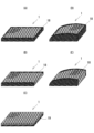
- FIGS 12A to 12E are schematic diagrams showing how protrusions 2 are formed by the method described above.
- Figure 12A when the above-mentioned formation of protrusions is performed on a three-dimensional mesh structure on which surface layers 51 and 52 have been formed, the area on the surface side of the interior of the structure is compressed to become center 53 of the protrusions, and the other areas remain as interior 54 of the structure.
- a protrusion is formed in which center 53 has a higher bulk density than interior 54, while surface layers 51 and 52 remain.
- a thick surface layer 55 is formed at the bottom due to compression.
- Figure 12B is an explanatory diagram of a case where the bulk density of the surface layer 51 of the three-dimensional mesh structure before the unevenness is formed is smaller than that of Figure 12A.
- By controlling the thickness and bulk density of the surface layer 51 of the mesh structure before the unevenness is formed it is possible to control the thickness and bulk density of the surface layer 51 of the convex parts.
- the thickness and bulk density of the surface layers 51, 52 of the mesh structure before the unevenness is formed can be controlled, for example, by adjusting the nozzle shape or the distance between the nozzles.
- FIG. 12C shows a case where the bulk density inside the structure before the unevenness is formed is two-layered, and the bulk density on the surface side is made relatively small, thereby making the bulk density of the center 53 of the convex portion 2 relatively small. This makes it possible to reduce the difference in bulk density between the center 53 and the inside 54, or conversely, to make the bulk density of the inside 54 larger than that of the center 53. If the bulk density inside the structure before the unevenness is multi-layered, the ratio of the bulk density of the inside 54 and the center 53 of the convex portion can also be controlled.
- One example of a method for making the bulk density two-layered before the unevenness is to adjust the distance between the nozzles of the die.
- the hardness of the convex portion can be adjusted by adjusting the thickness and bulk density of the surface layer 51 and the bulk density of the center 53 of the convex portion. In other words, both hard and soft convex portions can be formed as desired. Convex portions with different bulk densities can be freely designed.
- Figure 12D shows a case where the bulk density of the surface layer inside the structure before the unevenness is formed is increased to form two layers, and the bulk density of the center of the protrusion 2 is two layers, an upper layer 531 and a lower layer 532.
- the bulk density of the upper layer 531 is higher than that of the lower layer 532, but the reverse is also possible.
- Figure 12E shows a case where the bulk density of the back layer side inside the structure before the unevenness is formed is increased to form two layers, and the bulk density inside the structure is two layers, upper layer 541 and lower layer 542.
- the bulk density of lower layer 542 is made higher than that of upper layer 541, but the reverse is also possible. Also, three or four layers instead of two layers are possible.
- the three-dimensional net structure 1 can be formed by subjecting a molded product to thermal processing or ultrasonic processing, and the molded product can be a specially molded product.
- a molded product (A-1) can be subjected to thermal processing or ultrasonic processing to form an incline on the whole (A-2), and further subjected to thermal processing to form a depression 6, for example, in the center (A-3).
- a specially molded product (B-1) with raised parts 7 formed as holding parts on the left and right can be similarly compressed on the whole by thermal processing or ultrasonic processing (B-2), and further subjected to thermal processing to form a depression 6, for example, in the center (B-3).
- thermal processing or ultrasonic processing B-2
- thermal processing to form a depression 6, for example, in the center (B-3) for example, by controlling the processing conditions, it is possible to leave a protrusion 2 on the surface even in the inclined surface or the depression.
- the body pressure dispersion characteristics of the test specimens of Examples 1 to 5 and Comparative Examples 1 and 2 described below were measured with two subjects (one referred to as G (weight 85 kg) and the other as A (weight 48 kg)) sitting on them.
- G weight 85 kg
- A weight 48 kg
- an SR Soft Vision buttocks measuring device manufactured by Sumitomo Riko was used to obtain body pressure dispersion measurement data with the subjects sitting on the test specimens.
- Sumitomo Riko SR Soft Vision measuring device please refer to https://www.sumitomoriko.co.jp/product/health/SVZB922AM/.
- Table 1 The measurement results are shown in Table 1.
- Example 1 and Comparative Examples 1 to 3 were measured with two subjects lying on their backs.
- an SR Soft Vision whole-body measuring device manufactured by Sumitomo Riko was used to obtain body pressure dispersion measurement data with the subjects lying on their backs on the test specimens. The measurement results are shown in Table 2.
- the specimen of Example 1 is a three-dimensional network structure having a thickness of 8 cm, which is made of filaments having a line diameter (diameter) of 0.7 mm and has a plurality of protrusions arranged in a staggered pattern on the surface, and is made of polyethylene resin.
- the overall average bulk density is 0.090 g/cm 3
- the bulk density of the surface layer 2a is 0.161 g/cm 3 and the thickness is about 3 mm
- the bulk density of the flat back surface layer 11d (same as 111d in FIG.
- each protrusion 12 is 0.189 g/cm 3 and the thickness is 3 mm
- each protrusion is formed with approximately the same bulk density
- the average bulk density of each protrusion (including the surface layer 2a and the central portion 2b) is 0.10 g/cm 3
- the bulk density of the central portion 2b of the protrusion is 0.07 g/cm 3
- the bulk density of the inside 11c of the structure is 0.05 g/cm 3
- the number of protrusions is 500 per m 2 .
- the height of each protrusion 2 is uniform, and the height H of the protrusion is 7 mm.
- the width W of the protrusion is 55 mm.
- the average bulk density of the three-dimensional network structure body (excluding the protrusions, including the surface layer 11a, the interior 11c, and the back surface layer 11d) is 0.089 g/ cm3 .
- the specimen of Example 2 is a three-dimensional network structure having a thickness of 4.0 cm, which is made of filaments having a line diameter (diameter) of 1.0 mm and has a plurality of protrusions 2 arranged in a staggered pattern on the surface, formed of polyethylene resin.
- the bulk density of the surface layer 2a is 0.206 g/cm 3 and a thickness of 3 mm
- the bulk density of the back surface layer 11d is 0.185 g/cm 3 and a thickness of 3 mm
- the average bulk density of each protrusion 2 (including the surface layer 2a and the central portion 2b) is 0.055 g/cm 3
- the bulk density of the central portion 2b of the protrusion is 0.041 g/cm 3
- the bulk density of the inside 11c of the structure is 0.038 g/cm 3.
- the number of protrusions is 300 per m 2.
- the height of the protrusions 2 is uniform, and the height H1 of the protrusions is 16 mm.
- the width W of the protrusions is 50 mm.
- the three-dimensional network structure body (excluding the protrusions, including the surface layer 11a, the interior 11c, and the back surface layer 11d) has an average bulk density of 0.046 g/ cm3 .
- Example 3 The specimen of Example 3 was prepared by laminating a urethane sheet (thickness: 20 mm, bulk density: 0.02 g/cm 3 ) on the specimen of Example 1.
- the specimen of Example 4 is a three-dimensional network structure formed of polyethylene resin, consisting of filaments with a line diameter (diameter) of 0.4 mm, and having a corrugated surface with streak-like protrusions 4 formed on the surface.
- the thickness of the specimen is 11 cm.
- the overall average bulk density is 0.032 g/cm 3
- the bulk density of the surface layer 4a is 0.056 g/cm 3 and the thickness is 3 mm
- the bulk density of the back surface layer 11 d is 0.080 g/cm 3 and the thickness is 3 mm
- the bulk density of the center portion 4b of the streak-like protrusions is 0.027 g/cm 3 .
- each streak-like protrusion 4 (including the surface layer 4a and the central portion 4b) is 0.034 g/ cm3
- the average bulk density of the three-dimensional network structure body (excluding the streak-like protrusions 4, including the surface layer 11e, the interior 11c, and the back surface layer 11d) is 0.025 g/ cm3
- the height H2 of the streak-like protrusions 4 is 4 mm.
- Example 4 rotated 90 degrees in plan view.
- the specimen of Comparative Example 1 is a three-dimensional network structure made of colorless polyethylene resin, consisting of filaments with a line diameter of 0.8 mm, with no irregularities formed on the surface, and having a thickness of 6 cm.
- the overall average bulk density is 0.055 g/ cm3
- the front and back surfaces are provided with a surface layer and a back surface layer having a higher bulk density than the inside, the surface layer having a thickness of 3 mm and a bulk density of 0.127 g/ cm3 , the back surface layer having a thickness of 3 mm and a bulk density of 0.115 g/ cm3 , and the bulk density of the inside excluding the surface layer is 0.047 g/ cm3 .
- the test specimen for Comparative Example 2 is a urethane foam for mattresses with a thickness of 45 mm and a profiled surface with protrusions of 30 mm in height.
- the test specimen for Comparative Example 3 is a urethane foam for mattresses with a smooth surface.
- the present invention is not limited to the above-described embodiment, and various modifications, substitutions, deletions, etc. can be made without departing from the technical concept of the present invention. Modifications, equivalents, substitutions, deletions, etc. are also included in the technical scope of the present invention.
- the convex portions and streak-like convex portions do not need to be provided on the entire surface of the net-like structure, and can be provided only partially or in specific areas, depending on requirements.
- the three-dimensional mesh structure of the present invention is applicable to the filling and core materials of mattresses, cushions, sofas, beds, seats, etc.
Landscapes
- Engineering & Computer Science (AREA)
- Textile Engineering (AREA)
- Mechanical Engineering (AREA)
- Mattresses And Other Support Structures For Chairs And Beds (AREA)
- Nonwoven Fabrics (AREA)
Abstract
Description
2、102:凸部
2a、102a:表面層
2b、102b:中心部
3、103 :底部
4 :筋状凸部
4a :表面層
4b :中心部
5 :筋状底部
11、111 :三次元網状構造本体
11a、111a :(底部における)表面層
11c、111c :構造体内部
11d、111d :裏面側表面層
11e :(筋状底部における)表面層
51 :表面層
52 :表面層
53 :中心部
54 :構造体内部
55 :表面層(底部)
H :凸部の高さ
W :凸部の幅
Claims (14)
- 全体平均嵩密度が0.01~1.5g/cm3であり、ランダムループを有する複数の連続線条が部分的に融着され、クッションとして用いられる三次元網状構造体であって、
三次元網状構造本体と、
該三次元網状構造本体の特定の表面に形成され、厚み方向に突出する複数個の凸部を備え、
前記複数個の凸部は該凸部の頂部よりも高さの低い底部を介在させて連続して設けられ、前記複数個の凸部のうち少なくとも一つの凸部の平均嵩密度は前記三次元網状構造本体の平均嵩密度の1.05~6倍である、
三次元網状構造体。 - 前記凸部の形状はおわん型、円錐型、山形(頂部が平坦なものを除く)、または多角錐型であり、
前記複数個の凸部は、第1方向において、該凸部の頂部よりも高さの低い底部を介在させて連続して設けられ、かつ、前記複数個の凸部は、第1方向と直交する第2方向において、該凸部の頂部よりも高さの低い底部を介在させて連続して設けられる、
請求項1に記載の三次元網状構造体。 - 前記複数個の凸部の配列は千鳥状であり、
前記凸部および前記底部は、それぞれ前記三次元網状構造本体の内部の平均嵩密度よりも高い嵩密度を有する表面層を有し、前記底部における表面層は前記凸部の頂部における表面層よりも厚みが大きいか、または、前記底部の表面層の直下に連続して高密度部が存在することを特徴とする、
請求項1または2に記載の三次元網状構造体。 - 前記複数個の凸部は、前記表面層と前記表面層により被覆される中心部を有し、該表面層は該中心部よりも嵩密度が高いことを特徴とする、
請求項3に記載の三次元網状構造体。 - 前記複数個の凸部のうち少なくとも一つの凸部の前記中心部の平均嵩密度は、前記三次元網状構造本体の内部の平均嵩密度よりも高いことを特徴とする、請求項4に記載の三次元網状構造体。
- 前記凸部の数が1m2あたり100~2500個である、請求項1または2に記載の三次元網状構造体。
- ウレタンフォーム、不織シート、および別の三次元網状構造体のうち少なくとも一つと積層されるか、または、前記凸部を被覆するカバーとしてウレタンフォーム、不織布、またはダブルラッセル生地と積層される、請求項1または2に記載の三次元網状構造体。
- 前記凸部の配列は、直列状、千鳥状、又は格子状である、請求項1または2に記載の三次元網状構造体。
- 前記凸部の高さまたは平均嵩密度は、前記三次元網状構造体の領域によって異なる、請求項1または2に記載の三次元網状構造体。
- 前記凸部は、前記三次元網状構造本体の上面と下面に形成され、上面に形成された凸部の形状、嵩密度、高さ、または配置が下面に形成された凸部とは異なる、請求項1または2に記載の三次元網状構造体。
- 前記凸部が形成された特定の表面に、熱加工または超音波加工による窪み部、または傾斜部が形成され、該窪み部、該傾斜部には前記凸部が残っている、請求項1または2に記載の三次元網状構造体。
- 少なくとも対向する二つの側面に、前記三次元網状構造本体の平均嵩密度よりも高い高密度を有する高密度側面部を備えることを特徴とする、請求項1または2に記載の三次元網状構造体。
- 前記三次元網状構造体が長さ方向または横方向に伸長するのを抑制する伸長防止部材を備え、前記伸長防止部材は、少なくとも対向する二つの側面に存在する、前記三次元網状構造本体の平均嵩密度よりも高い高密度を有する高密度側面部であることを特徴とする、請求項1または2に記載の三次元網状構造体。
- 請求項1または2に記載の三次元網状構造体を含む、シートクッション、マットレス、枕または椅子。
Priority Applications (2)
| Application Number | Priority Date | Filing Date | Title |
|---|---|---|---|
| CN202480027786.8A CN121001619A (zh) | 2023-08-10 | 2024-08-09 | 三维网状结构体 |
| EP24851959.7A EP4696200A1 (en) | 2023-08-10 | 2024-08-09 | Three dimensional network structure |
Applications Claiming Priority (2)
| Application Number | Priority Date | Filing Date | Title |
|---|---|---|---|
| JP2023131112A JP7562178B1 (ja) | 2023-08-10 | 2023-08-10 | 三次元網状構造体 |
| JP2023-131112 | 2023-08-10 |
Publications (1)
| Publication Number | Publication Date |
|---|---|
| WO2025033542A1 true WO2025033542A1 (ja) | 2025-02-13 |
Family
ID=92969920
Family Applications (1)
| Application Number | Title | Priority Date | Filing Date |
|---|---|---|---|
| PCT/JP2024/028659 Pending WO2025033542A1 (ja) | 2023-08-10 | 2024-08-09 | 三次元網状構造体 |
Country Status (4)
| Country | Link |
|---|---|
| EP (1) | EP4696200A1 (ja) |
| JP (1) | JP7562178B1 (ja) |
| CN (1) | CN121001619A (ja) |
| WO (1) | WO2025033542A1 (ja) |
Families Citing this family (1)
| Publication number | Priority date | Publication date | Assignee | Title |
|---|---|---|---|---|
| JP7709242B1 (ja) * | 2024-12-11 | 2025-07-16 | 株式会社シーエンジ | 立体網状構造体の製造装置および立体網状構造体の製造方法 |
Citations (14)
| Publication number | Priority date | Publication date | Assignee | Title |
|---|---|---|---|---|
| JPS6079357U (ja) * | 1983-11-09 | 1985-06-03 | 株式会社ブリヂストン | 寝具用マツトレス |
| JP2001328153A (ja) | 2000-03-15 | 2001-11-27 | Shiienji:Kk | 立体網状構造体の製造方法及び立体網状構造体の製造装置 |
| JP2006130283A (ja) | 2004-09-02 | 2006-05-25 | Jatecx:Kk | 体圧分散構造体及びその製造方法。 |
| JP2006200118A (ja) | 2004-12-21 | 2006-08-03 | Toyobo Co Ltd | ソフト反発性を有する弾性網状構造体 |
| WO2012157289A1 (ja) | 2011-05-18 | 2012-11-22 | 株式会社シーエンジ | 立体網状構造体、立体網状構造体の製造方法および立体網状構造体の製造装置 |
| JP5454733B1 (ja) | 2013-10-01 | 2014-03-26 | 東洋紡株式会社 | 圧縮耐久性に優れた網状構造体 |
| JP2015211703A (ja) | 2014-05-01 | 2015-11-26 | アイリスオーヤマ株式会社 | 複層構造マットレス |
| WO2016125766A1 (ja) | 2015-02-04 | 2016-08-11 | 東洋紡株式会社 | 低反発性に優れた網状構造体 |
| JP2016214762A (ja) * | 2015-05-25 | 2016-12-22 | 株式会社ブリヂストン | クッション材 |
| JP2017226230A (ja) | 2014-02-23 | 2017-12-28 | 株式会社シーエンジ | クッション用中材及びクッション |
| JP3217938U (ja) * | 2018-06-07 | 2018-09-13 | ヤマト産業株式会社 | マットレス |
| JP2020141784A (ja) * | 2019-03-05 | 2020-09-10 | 株式会社エアウィーヴ | クッション部材およびその製造方法 |
| JP2022033210A (ja) * | 2019-09-17 | 2022-02-28 | 株式会社シーエンジ | コイルスプリング用緩衝材およびクッション体 |
| JP2025103345A (ja) | 2023-12-27 | 2025-07-09 | 株式会社クボタ | 受口に挿口を挿入する管継手に用いられるシール材およびこのシール材を用いた管継手 |
Family Cites Families (1)
| Publication number | Priority date | Publication date | Assignee | Title |
|---|---|---|---|---|
| JPS6083618U (ja) * | 1983-11-14 | 1985-06-10 | 株式会社ブリヂストン | 寝具用マツトレス |
-
2023
- 2023-08-10 JP JP2023131112A patent/JP7562178B1/ja active Active
-
2024
- 2024-08-09 EP EP24851959.7A patent/EP4696200A1/en active Pending
- 2024-08-09 WO PCT/JP2024/028659 patent/WO2025033542A1/ja active Pending
- 2024-08-09 CN CN202480027786.8A patent/CN121001619A/zh active Pending
Patent Citations (14)
| Publication number | Priority date | Publication date | Assignee | Title |
|---|---|---|---|---|
| JPS6079357U (ja) * | 1983-11-09 | 1985-06-03 | 株式会社ブリヂストン | 寝具用マツトレス |
| JP2001328153A (ja) | 2000-03-15 | 2001-11-27 | Shiienji:Kk | 立体網状構造体の製造方法及び立体網状構造体の製造装置 |
| JP2006130283A (ja) | 2004-09-02 | 2006-05-25 | Jatecx:Kk | 体圧分散構造体及びその製造方法。 |
| JP2006200118A (ja) | 2004-12-21 | 2006-08-03 | Toyobo Co Ltd | ソフト反発性を有する弾性網状構造体 |
| WO2012157289A1 (ja) | 2011-05-18 | 2012-11-22 | 株式会社シーエンジ | 立体網状構造体、立体網状構造体の製造方法および立体網状構造体の製造装置 |
| JP5454733B1 (ja) | 2013-10-01 | 2014-03-26 | 東洋紡株式会社 | 圧縮耐久性に優れた網状構造体 |
| JP2017226230A (ja) | 2014-02-23 | 2017-12-28 | 株式会社シーエンジ | クッション用中材及びクッション |
| JP2015211703A (ja) | 2014-05-01 | 2015-11-26 | アイリスオーヤマ株式会社 | 複層構造マットレス |
| WO2016125766A1 (ja) | 2015-02-04 | 2016-08-11 | 東洋紡株式会社 | 低反発性に優れた網状構造体 |
| JP2016214762A (ja) * | 2015-05-25 | 2016-12-22 | 株式会社ブリヂストン | クッション材 |
| JP3217938U (ja) * | 2018-06-07 | 2018-09-13 | ヤマト産業株式会社 | マットレス |
| JP2020141784A (ja) * | 2019-03-05 | 2020-09-10 | 株式会社エアウィーヴ | クッション部材およびその製造方法 |
| JP2022033210A (ja) * | 2019-09-17 | 2022-02-28 | 株式会社シーエンジ | コイルスプリング用緩衝材およびクッション体 |
| JP2025103345A (ja) | 2023-12-27 | 2025-07-09 | 株式会社クボタ | 受口に挿口を挿入する管継手に用いられるシール材およびこのシール材を用いた管継手 |
Non-Patent Citations (1)
| Title |
|---|
| See also references of EP4696200A1 |
Also Published As
| Publication number | Publication date |
|---|---|
| JP7562178B1 (ja) | 2024-10-07 |
| CN121001619A (zh) | 2025-11-21 |
| JP2025025894A (ja) | 2025-02-21 |
| EP4696200A1 (en) | 2026-02-18 |
Similar Documents
| Publication | Publication Date | Title |
|---|---|---|
| CN109068863B (zh) | 垫用芯材及床用垫 | |
| US10233073B2 (en) | Three-dimensional striped structure | |
| CA2811506C (en) | Multi-walled gelastic mattress system | |
| US20160174725A1 (en) | Core material for cushion, and cushion | |
| JP7300188B2 (ja) | 立体網状構造体 | |
| US20180213954A1 (en) | Two-sided pillow | |
| KR102674703B1 (ko) | 쿠셔닝 구조물 | |
| US20090199341A1 (en) | Chambered pillow | |
| US20120015151A1 (en) | Alternating pattern gel cushioning elements and related methods | |
| JP6539912B2 (ja) | 敷き寝具 | |
| JP7562178B1 (ja) | 三次元網状構造体 | |
| JP3836851B2 (ja) | クッション材 | |
| JP2006130283A (ja) | 体圧分散構造体及びその製造方法。 | |
| KR101998556B1 (ko) | 온도제어가 가능한 기능성 베개 | |
| US20100024127A1 (en) | Body support mattress pad | |
| JP3686691B2 (ja) | 座席のパッド用繊維系クッション体 | |
| US20220346566A1 (en) | Heat-dissipating bedding product | |
| JP7429453B2 (ja) | コイルスプリング用緩衝材およびクッション体 | |
| JP7557213B2 (ja) | 硬化高反発型マットレスの製造方法 | |
| JP6808218B2 (ja) | クッション品およびその製造方法 | |
| US20250178269A1 (en) | Seat cushion, and method for manufacturing same | |
| JP7863933B1 (ja) | 硬化ポリエステルシートを用いた硬化高反発製品の製造方法 | |
| JP3249416U (ja) | 硬化高反発型寝具及び硬化高反発インテリア製品 | |
| JP7573891B2 (ja) | 硬化高反発クッションおよび硬化高反発まくら | |
| CN217447291U (zh) | 一种护颈枕芯 |
Legal Events
| Date | Code | Title | Description |
|---|---|---|---|
| 121 | Ep: the epo has been informed by wipo that ep was designated in this application |
Ref document number: 24851959 Country of ref document: EP Kind code of ref document: A1 |
|
| WWE | Wipo information: entry into national phase |
Ref document number: 2024851959 Country of ref document: EP |
|
| ENP | Entry into the national phase |
Ref document number: 2024851959 Country of ref document: EP Effective date: 20251110 |
|
| ENP | Entry into the national phase |
Ref document number: 2024851959 Country of ref document: EP Effective date: 20251110 |
|
| ENP | Entry into the national phase |
Ref document number: 2024851959 Country of ref document: EP Effective date: 20251110 |
|
| ENP | Entry into the national phase |
Ref document number: 2024851959 Country of ref document: EP Effective date: 20251110 |
|
| ENP | Entry into the national phase |
Ref document number: 2024851959 Country of ref document: EP Effective date: 20251110 |
|
| ENP | Entry into the national phase |
Ref document number: 2024851959 Country of ref document: EP Effective date: 20251110 |
|
| ENP | Entry into the national phase |
Ref document number: 2024851959 Country of ref document: EP Effective date: 20251110 |
|
| ENP | Entry into the national phase |
Ref document number: 2024851959 Country of ref document: EP Effective date: 20251110 |
|
| ENP | Entry into the national phase |
Ref document number: 2024851959 Country of ref document: EP Effective date: 20251110 |
|
| WWP | Wipo information: published in national office |
Ref document number: 2024851959 Country of ref document: EP |
|
| NENP | Non-entry into the national phase |
Ref country code: DE |