WO2025046758A1 - ピストンリング - Google Patents
ピストンリング Download PDFInfo
- Publication number
- WO2025046758A1 WO2025046758A1 PCT/JP2023/031339 JP2023031339W WO2025046758A1 WO 2025046758 A1 WO2025046758 A1 WO 2025046758A1 JP 2023031339 W JP2023031339 W JP 2023031339W WO 2025046758 A1 WO2025046758 A1 WO 2025046758A1
- Authority
- WO
- WIPO (PCT)
- Prior art keywords
- piston ring
- coating
- intermediate layer
- gas
- piston
- Prior art date
- Legal status (The legal status is an assumption and is not a legal conclusion. Google has not performed a legal analysis and makes no representation as to the accuracy of the status listed.)
- Pending
Links
Images


Classifications
-
- F—MECHANICAL ENGINEERING; LIGHTING; HEATING; WEAPONS; BLASTING
- F16—ENGINEERING ELEMENTS AND UNITS; GENERAL MEASURES FOR PRODUCING AND MAINTAINING EFFECTIVE FUNCTIONING OF MACHINES OR INSTALLATIONS; THERMAL INSULATION IN GENERAL
- F16J—PISTONS; CYLINDERS; SEALINGS
- F16J9/00—Piston-rings, e.g. non-metallic piston-rings, seats therefor; Ring sealings of similar construction
- F16J9/26—Piston-rings, e.g. non-metallic piston-rings, seats therefor; Ring sealings of similar construction characterised by the use of particular materials
-
- F—MECHANICAL ENGINEERING; LIGHTING; HEATING; WEAPONS; BLASTING
- F02—COMBUSTION ENGINES; HOT-GAS OR COMBUSTION-PRODUCT ENGINE PLANTS
- F02F—CYLINDERS, PISTONS OR CASINGS, FOR COMBUSTION ENGINES; ARRANGEMENTS OF SEALINGS IN COMBUSTION ENGINES
- F02F5/00—Piston rings, e.g. associated with piston crown
Definitions
- This disclosure relates to piston rings.
- Patent Document 1 discloses replacing piston rings from conventional spring steel or carbon steel to chromium-based stainless steel, which has better heat resistance.
- piston rings made of chromium-based stainless steel can increase the amount of blow-by gas, a type of emission, even under conditions where thermal settling does not occur.
- This disclosure provides a piston ring that is useful for sufficiently reducing the amount of blow-by gas.
- the inventors have focused on the fact that the amount of blow-by gas and fuel economy vary depending on the material that constitutes the outer circumferential surface of the piston ring. As a result of repeating experiments by changing the material and thickness of the coating, they have found that the thermal resistance value of the coating correlates with fuel economy and blow-by gas, that is, when the thermal resistance value of the coating is within a predetermined range, the amount of blow-by gas can be sufficiently reduced.
- the thermal resistance value is a value expressed by the following formula 1, and the thermal resistance value and thermal conductivity have a relationship expressed by the following formula 2.
- Thermal resistance value film thickness / (specific gravity x specific heat x thermal diffusivity) (Equation 1)
- Thermal resistance value film thickness / thermal conductivity (Equation 2)
- the piston ring according to the present disclosure includes a piston ring base material having a butt portion and a coating covering at least an outer circumferential surface of the piston ring base material, and the thermal resistance value of the coating is 2.0 ⁇ 10 -6 to 12.0 ⁇ 10 -6 m2 ⁇ K/W.
- the amount of blow-by gas can be sufficiently reduced.
- the present inventors speculate that the main reason is as follows. That is, the temperature of the piston ring rises with the operation of the engine, and the piston ring expands appropriately with this, narrowing the gap at the butt of the piston ring. If the thermal resistance value of the film is 2.0 ⁇ 10 ⁇ 6 m 2 ⁇ K/W or more, the piston ring base material is heated by heat from the piston, while heat dissipation to the cylinder liner is suppressed, so that the gap at the butt of the piston ring is sufficiently narrowed by thermal expansion, and the amount of blow-by gas can be suppressed.
- the thermal resistance value of the film is 12.0 ⁇ 10 ⁇ 6 m 2 ⁇ K/W or less, the temperature of the piston ring base material can be suppressed from rising excessively, and thermal settling of the piston ring, which causes an increase in the amount of blow-by gas, can be prevented.
- the present disclosure provides a piston ring that is useful for sufficiently reducing the amount of blow-by gas.
- FIG. 1 is a plan view illustrating a schematic diagram of one embodiment of a piston ring according to the present disclosure.
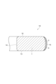
- FIG. 2 is a cross-sectional view taken along line II-II shown in FIG.
- FIG. 3 is a cross-sectional view that diagrammatically shows another embodiment of a piston ring according to the present disclosure.
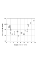
- FIG. 4 is a graph showing the results of the examples and comparative examples.
- FIG. 1 is a plan view showing a schematic diagram of a piston ring according to this embodiment.
- FIG. 2 is a cross-sectional view taken along line II-II shown in FIG. 1.
- a piston ring 10 is annular and has a butt portion 11.
- the piston ring 10 has a pair of side surfaces 12, 13, an inner peripheral surface 14, and an outer peripheral surface 15.
- the side surfaces 12, 13 intersect with the inner peripheral surface 14, and are, for example, substantially perpendicular to the inner peripheral surface 14.
- the outer diameter d1 of the piston ring 10 is, for example, 40 to 300 mm.
- the gap S1 of the butt portion 11 is, for example, 0.15 to 0.60 mm.
- the piston ring 10 may be a perfect circle or an ellipse in a plan view.
- the piston ring 10 comprises a piston ring substrate 1 having a joint portion 11, a coating 5 constituting the outer peripheral surface 15 of the piston ring 10, and an intermediate layer 3.
- the intermediate layer 3 is provided between the piston ring substrate 1 and the coating 5, and serves to, for example, increase the adhesion of the coating 5 to the piston ring substrate 1.
- the cross section of the piston ring 10 is approximately rectangular, and the outer peripheral surface 15 of the piston ring 10 may be rounded and bulge outward.
- the outer peripheral surface 15 is a surface that slides against the inner surface of the cylinder liner.
- Piston ring 10 is a pressure ring for an internal combustion engine (e.g., a high-load diesel engine or an automobile engine).
- the pressure ring is mounted, for example, in a ring groove formed on the side of the piston.
- the pressure ring is exposed to an environment with high thermal load in the engine.
- One of the functions of the pressure ring is gas sealing.
- the pressure ring suppresses gas (blow-by gas) leaking from the combustion chamber side to the crank chamber side.
- An increase in blow-by gas leads to deterioration of engine oil, reduced fuel efficiency, and increased environmental load.
- the joint of the piston ring is one of the leakage paths for blow-by gas. From the viewpoint of suppressing blow-by gas, it is desirable that the gap at the joint is as small as possible when the engine is running.
- Another function of the compression ring is to cool the piston by dissipating heat.
- the piston is heated by the heat of the combustion chamber, and the heat from the piston is dissipated to the cylinder liner through the compression ring. If the temperature of the piston rises excessively, the piston material will adhere and the engine's fuel efficiency will decrease significantly. On the other hand, if there is excessive heat dissipation via the piston and piston ring, the thermal efficiency of the engine will deteriorate, leading to reduced fuel efficiency. Therefore, from the perspective of fuel efficiency, the thermal resistance of the piston ring is required to be within a specified range.
- the piston ring base material 1 is made of a heat-resistant alloy.
- the alloy include martensitic stainless steel, such as chromium-based stainless steel, tool steel, heat-resistant steel, etc.
- the intermediate layer 3 plays a role in enhancing the adhesion between the piston ring substrate 1 and the coating 5.
- the thickness of the intermediate layer 3 is preferably 0.1 to 3.0 ⁇ m, and more preferably 0.5 to 2.5 ⁇ m.
- the thickness of the intermediate layer 3 is preferably 3.0 ⁇ m or less.
- the intermediate layer 3 may be made of, for example, chromium, or may be made of chromium containing Si, Al, etc.
- the Si content in the intermediate layer 3 is preferably 2.0 to 10.0 at%.
- the Si content is 2.0 at% or more, the thermal resistivity of the intermediate layer 3 is increased, and the total thermal resistivity of the intermediate layer 3 and the coating 5 is increased, which further contributes to suppressing the amount of blow-by gas.
- the Si content is 10.0 at% or less, the effect of maintaining the internal stress relaxation effect of the intermediate layer 3 is achieved.
- the lower limit of the Si content may be 2.5 at% or 3.0 at%.
- the upper limit of the Si content may be 8.5 at% or 6.0 at%.
- the Al content in the intermediate layer 3 is preferably 10.0 to 50.0 at%.
- the thermal resistivity of the intermediate layer 3 is increased, and the total thermal resistivity of the intermediate layer 3 and the coating 5 is increased, which further contributes to suppressing the amount of blow-by gas.
- the upper limit of the Al content may be 25 at% or 20 at%.
- the coating 5 is made of chromium nitride containing Si.
- the coating 5 is made of chromium nitride containing Al.
- the coating 5 constitutes the outer peripheral surface 15 of the piston ring 10.
- the thickness of the coating 5 is preferably 3 to 100 ⁇ m, and more preferably 5 to 70 ⁇ m.
- the coating 5 is composed of, for example, a metal nitride such as chromium nitride or titanium nitride, or an amorphous carbon film.
- the coating 5 may be a single layer or a laminate of two or more layers, so long as it has a predetermined overall thermal resistance value.
- An example of a laminate of two or more layers is a laminate of a chromium nitride layer and a chromium nitride layer containing carbon.
- the surface (outer peripheral surface 15) of the coating 5 is made of metal nitride or amorphous carbon, which can suppress the progression of wear of the coating 5 and can maintain the functionality of the coating 5 for a sufficiently long period of time.
- the coating 5 may further contain Si, Al, C, H, etc. If the coating 5 contains Si or Al, blow-by gas can be more effectively suppressed.
- the Si content in the coating 5 is preferably 1.0 to 10.0 at%.
- Chromium nitride with a Si content of 1.0 at% or more is made of fine crystal grains and has good crack resistance and peeling resistance.
- chromium nitride with a Si content of 10.0 at% or less is prone to forming an appropriate amorphous phase and has good crack resistance. Therefore, the coating 5 made of chromium nitride containing Si within the above range can maintain the effects of improving fuel efficiency and suppressing the amount of blow-by gas even in a more severe usage environment.
- chromium nitride containing Si within the above range has excellent wear resistance. Therefore, by making the sliding surface out of the chromium nitride, the effects of improving fuel efficiency and suppressing the amount of blow-by gas can be maintained for a longer period.
- the lower limit of the Si content may be 1.5 at% or 2.0 at%.
- the upper limit of the Si content may be 8.0 at% or 6.0 at%.
- the Al content in the coating 5 is preferably 10 to 50 at%.
- the thermal conductivity of the material constituting the coating 5 can be sufficiently reduced, and the coating 5 can be given heat insulation performance.
- the wear resistance of the coating 5 can be increased, and the effects of improving fuel efficiency and suppressing the amount of blow-by gas can be maintained for a longer period.
- the Al content 50 at% or less Al can be sufficiently dissolved in the chromium nitride, and a uniform coating 5 can be obtained.
- chromium nitride containing Al within the above range has excellent wear resistance.
- the lower limit of the Al content may be 13 at% or 15 at%.
- the upper limit of the Al content may be 25 at% or 20 at%.
- the thermal resistance value of the coating 5 is 2.0 ⁇ 10 ⁇ 6 m 2 ⁇ K/W or more, preferably 2.5 ⁇ 10 ⁇ 6 m 2 ⁇ K/W or more, more preferably 4.0 ⁇ 10 ⁇ 6 m 2 ⁇ K/W or more, even more preferably 5.0 ⁇ 10 ⁇ 6 m 2 ⁇ K/W or more, and most preferably 7.0 ⁇ 10 ⁇ 6 m 2 ⁇ K/W or more.
- the gap of the butt portion 11 is reduced, and the amount of blow-by gas can be suppressed.
- the piston ring 10 has heat-shielding performance, the temperature drop of the combustion chamber can be suppressed. In other words, by providing the piston ring 10 with an appropriate heat insulating performance, the amount of blow-by gas can be suppressed and an engine having good fuel economy characteristics can be realized.
- the thermal resistance value of the coating 5 is 12.0 ⁇ 10 ⁇ 6 or less, preferably 11.0 ⁇ 10 ⁇ 6 m 2 ⁇ K/W or less, more preferably 10.3 ⁇ 10 ⁇ 6 m 2 ⁇ K/W or less, and even more preferably 9.0 ⁇ 10 ⁇ 6 m 2 ⁇ K/W or less.
- the "thermal resistance value” referred to here means the value obtained by the laser thermoreflectance method.
- a molybdenum (Mo) film is formed on the mirror-like surface of a sample, and the thin film surface is irradiated with a laser to heat it periodically, and the thermal diffusivity is obtained by analyzing the modulation of the reflectivity on the metal surface. More specifically, the sample surface is first heated periodically by the laser light, and heat is diffused from the surface of the metal thin film into the sample. At this time, the surface temperature of the sample changes depending on the thermal conductivity of the sample.
- a reflected light corresponding to the temperature modulation of the sample surface is obtained by irradiating a continuous wave detection laser light that is not modulated coaxially with the heating light.
- the phase delay of the reflected light with respect to the heating period is small.
- the phase delay of the reflected light with respect to the heating period is large.
- the thermal diffusivity of the sample is obtained by analyzing the phase delay of the reflected light with respect to the heating light.
- the thermal resistance value is calculated by applying this thermal diffusivity value and the specific heat value obtained using differential scanning calorimetry to Equation 1.
- the thermal resistance value may be obtained by a method other than the laser thermoreflection method.
- the thermal diffusivity and specific heat may be obtained by the laser flash method, and these may be applied to formula 1 to calculate the thermal resistance value.
- the laser flash method a pulsed laser light for heating is irradiated onto a disk-shaped sample held in a vacuum, and the thermal diffusivity and specific heat are obtained by analyzing the temperature history of the rear surface of the sample.
- a disk-shaped sample is placed in a vacuum and the entire sample is kept at a constant temperature T 0.
- the entire surface of the sample is pulse-heated by a laser light with a pulse width of about 100 ⁇ s, and the temperature change of the rear surface is measured.
- the thermal diffusivity can be obtained by applying the time t half required for the entire sample to reach half the uniform temperature and the thickness L of the sample to formula 3.
- the specific heat can be determined by applying the weight W s and final temperature T s of the sample, and the specific heat C p,r , weight W r and final temperature T r of the reference substance to Equation 4.
- Thermal diffusivity 0.1388 ⁇ L 2 /t half (Formula 3)
- Specific heat C p, r ⁇ W r ⁇ (T r - T 0 )/(W s ⁇ (T s - T 0 )) (Formula 4)
- the piston ring 10 is manufactured, for example, by the following process.
- the intermediate layer 3 and the coating 5 in steps (b) and (c) can be formed by physical vapor deposition.
- physical vapor deposition include ion plating and sputtering. All of these physical vapor deposition methods are carried out in a vacuum chamber, and the pressure in the vacuum chamber is set to a range of 1 to 6 Pa, for example.
- the bias voltage is set to a range of -1 to 18 V, for example.
- a piston ring 10 having an intermediate layer 3 is exemplified, but as long as sufficient adhesion of the coating 5 to the piston ring base material 1 can be ensured, the intermediate layer 3 does not have to be provided.
- the coating 5 is formed directly on the outer peripheral surface of the piston ring base material 1.
- the piston ring base material 1 may be one in which at least the outer peripheral surface has been subjected to a surface treatment.
- the present disclosure relates to the following: [1] A piston ring base material having a butt portion; A coating that covers at least an outer peripheral surface of the piston ring base material; Equipped with A piston ring, wherein the thermal resistance value of the coating is 2.0 ⁇ 10 ⁇ 6 to 12.0 ⁇ 10 ⁇ 6 m 2 ⁇ K/W. [2] The piston ring according to [1], wherein the coating contains Al or Si. [3] The piston ring according to [1] or [2], further comprising an intermediate layer formed on a surface of the piston ring base material, the coating being formed on a surface of the intermediate layer. [4] The piston ring according to [3], wherein the intermediate layer contains Al or Si.
- a ring having the following composition corresponding to SUS440 and having a gap between the ends of the piston ring and the piston is prepared.
- nitrided layer was formed on the surface of the piston ring substrate by nitriding under the following conditions. That is, first, the piston ring substrate was degreased and cleaned, and then placed in a chamber. Next, ammonia gas was added to the chamber by gas nitriding, and nitriding was performed under the conditions of a nitriding temperature of 570°C and a treatment time of 2 hours. The thickness of the nitrided layer was 60 ⁇ m.
- Examples 1 to 4 and Comparative Examples 2 to 4 The piston rings according to Experimental Examples 1 to 4 and Comparative Examples 2 to 4 were manufactured through the following three steps. The film-forming time in each step was appropriately adjusted according to the target thermal resistance value of the film or the film thickness of the intermediate layer.
- Step of cleaning the surface of the substrate First, the piston ring substrate was degreased and cleaned, and then placed in a chamber. Next, the inside of the chamber was made into a vacuum atmosphere of 1.0 ⁇ 10 ⁇ 2 Pa, and then the inside of the chamber was replaced with argon gas to set the argon pressure to 1.0 Pa. Then, the piston ring substrate was bombarded and cleaned by glow discharge under the condition of a bias voltage of ⁇ 700 V.
- Examples 5 and 6 Piston rings according to Examples 5 and 6 were produced in the same manner as in Example 2, except that the following (c-2) step was carried out instead of the (c-1) step.
- (c-2) A process of forming a coating in which two types of layers are laminated by an ion plating method. In the film formation by the ion plating method, CrN(C) and CrN were deposited alternately. The film formation time was adjusted so that the lamination ratio of CrN(C) and CrN was 1:2.
- Examples 7 and 8 and Comparative Examples 7 and 8 Piston rings according to Examples 7 and 8 and Comparative Examples 7 and 8 were produced in the same manner as in Example 2, except that in the step (c-1), the film was formed under the following conditions.
- Example 14 A piston ring according to Example 14 was produced in the same manner as in Example 1, except that in the step (c-1), a Cr-Si alloy (Si content: 10 at %) was used as the target.
- the thickness of the coating was measured by cross-sectional observation using the following method. That is, first, the piston ring was cut perpendicular to the coating surface, and embedded in resin so that the cut surface was exposed. Next, the surface where the cut surface was exposed was wet polished using waterproof abrasive paper, and then finish polishing was performed using diamond film #8000 to obtain a sample for cross-sectional observation. The surface of the obtained sample was then magnified and observed using an optical microscope, and the thickness of the coating was measured.
- the specific gravity of the coating was calculated from the volume determined from the coating thickness and the area of the treated surface of the piston ring, and from the change in weight of the piston ring before and after the coating treatment.
- the specific heat of the film was measured using a differential scanning calorimeter (apparatus name: DSC-50, manufactured by Shimadzu Corporation). The measurement was performed under conditions conforming to JIS R1672:2006 using a thin film prepared under the same conditions as the film on a piston ring as the sample.
- the thermal diffusivity of the coating was measured by preparing a measurement sample in the following manner and using a laser heat reflection method. That is, first, the piston ring was cut in a direction perpendicular to the coating surface, and embedded in resin so that the cut surface was exposed. Next, the surface (measurement surface) where the cut surface was exposed was wet-polished with waterproof abrasive paper, and then finished by polishing with diamond film #8000, so that the cut surface of the piston ring was polished until it became a mirror surface. Furthermore, a Mo film of 50 nm was prepared on the measurement surface strip by a sputtering method.
- the resin was cut into small pieces using a fine cutter, and then the measurement surface was processed to 10 mm x 10 mm or less and a height of 3 mm or less using a surface grinder, to obtain a measurement sample for laser heat reflection measurement.
- the thermal diffusivity of the obtained measurement sample was measured by a laser thermal reflection method.
- the measurement was performed using a thermal property microscope (device name: Thermal Microscope TM3, manufactured by Bethel Co., Ltd.) under the following conditions.
- the measurement position was set so that the outer peripheral surface of the coating and the piston ring base material were within the measurement range, and the average value of 30 measurements was used as the measurement result.
- Heating laser shape 28 ⁇ m x 25 ⁇ m ellipse Heating laser wavelength: 808 nm
- Modulation frequency Modulation frequency is 1MHz
- Detection laser shape Circular with a diameter of 3 ⁇ m
- Detection laser wavelength 658 nm Measurement range: width 120 ⁇ m x depth 60 ⁇ m
- Measurement pitch 2 ⁇ m
Landscapes
- Engineering & Computer Science (AREA)
- General Engineering & Computer Science (AREA)
- Mechanical Engineering (AREA)
- Chemical & Material Sciences (AREA)
- Combustion & Propulsion (AREA)
- Pistons, Piston Rings, And Cylinders (AREA)
- Physical Vapour Deposition (AREA)
Abstract
Description
熱抵抗値=膜厚/(比重×比熱×熱拡散率) (式1)
熱抵抗値=膜厚/熱伝導率 (式2)
図1は本実施形態に係るピストンリングを模式的に示す平面図である。図2は図1に示すII-II線における断面図である。図1に示すように、ピストンリング10は環状であり、合口部11有する。ピストンリング10は、一対の側面12,13と、内周面14と、外周面15とを有している。側面12,13は、内周面14に交差しており、例えば、内周面14に略直交している。ピストンリング10の外径d1は、例えば40~300mmである。合口部11の隙間S1は、例えば0.15~0.60mmである。ピストンリング10は、平面視で真円状でもよいし、楕円状でもよい。
ピストンリング基材1は、耐熱性を有する合金で構成されている。合金の具体例として、クロム系ステンレス鋼に代表されるマルテンサイト系ステンレス鋼又は工具鋼又は耐熱鋼等が挙げられる。ピストンリング基材がマルテンサイト系ステンレス鋼で構成されることで、ピストンリング基材の熱へたりが抑制され、高温で使用される場合であっても、良好なガスシール性を維持できるピストンリングが実現される。
中間層3は、上述のとおり、ピストンリング基材1と皮膜5の密着性を高める役割を果たす。中間層3の厚さは、好ましくは0.1~3.0μmであり、より好ましくは0.5~2.5μmである。中間層3の厚さが0.1μm以上であることで、ピストンリング基材1と皮膜5がおのおの有する内部応力の緩和による密着性の向上という効果が奏され、他方、中間層3が過剰に厚すぎると、内部応力の緩和効果が飽和する一方で、成膜コストが上昇する傾向にある。したがって中間層3の厚さは3.0μm以下が望ましい。
皮膜5は、上述のとおり、ピストンリング10の外周面15を構成している。皮膜5の厚さは、好ましくは3~100μmであり、より好ましくは5~70μmである。皮膜5の厚さが3μm以上であることで、ピストンリング10の外周面15とシリンダライナーとの摺接による皮膜5の耐久性を高くできる効果を得るだけでなく、ピストンリング10の熱抵抗率増大による燃費の向上やブローバイガス量の抑制という効果が奏され、他方、100μm以下であることで、ピストンリング基材1の温度が過度に上昇することを抑制でき、ブローバイガス量増加の原因となるピストンリング10の熱へたりを防止できるのみならず、高い生産性を確保できるという効果が奏される。
熱拡散率=0.1388×L2/thalf (式3)
比熱=Cp,r×Wr×(Tr-T0)/(Ws×(Ts-T0)) (式4)
ピストンリング10は、例えば以下の工程によって製造される。
(a)ピストンリング基材1の表面を洗浄する工程。
(b)ピストンリング基材1の少なくとも外周面を覆うように中間層3を形成する工程。
(c)中間層3の表面上に皮膜5を形成する工程。
[1]
合口部を有するピストンリング基材と、
前記ピストンリング基材の少なくとも外周面を被覆する皮膜と、
を備え、
前記皮膜の熱抵抗値が2.0×10⁻⁶~12.0×10⁻⁶m2・K/Wである、ピストンリング。
[2]
前記皮膜がAl又はSiを含む、[1]に記載のピストンリング。
[3]
前記ピストンリング基材の表面上に形成された中間層を更に備え、前記中間層の表面上に前記皮膜が形成されている、[1]又は[2]に記載のピストンリング。
[4]
前記中間層がAl又はSiを含む、[3]に記載のピストンリング。
[5]
前記皮膜はSiが含有された窒化クロムで構成され且つ前記中間層はSiが含有されたクロムで構成されている、[3]又は[4]に記載のピストンリング。
[6]
前記皮膜はAlが含有された窒化クロムで構成され且つ前記中間層はAlが含有されたクロムで構成されている、[3]~[5]のいずれかに記載のピストンリング。
・Fe:80.4質量%
・C:0.85質量%
・Cr:17.0質量%
・Si:0.5質量%
・Mn:0.5質量%
・その他元素:残部
ピストンリング基材の表面に以下の条件で窒化処理を施すことによって窒化層を形成した。すなわち、まず、ピストンリングの基材を脱脂及び洗浄した後、チャンバー内に設置した。次いで、ガス窒化法により、チャンバー内にアンモニアガスを添加し、窒化温度570℃、処理時間2時間の条件で窒化処理をした。窒化層の厚さは60μmであった。
実験例1~4及び比較例2~4に係るピストンリングを以下の3つの工程を経て作製した。なお、各工程における成膜時間は、目標とする皮膜の熱抵抗値又は中間層の膜厚に応じ、適宜調整した。
まず、上記ピストンリング基材を脱脂及び洗浄した後、チャンバー内に設置した。次いで、チャンバー内を1.0×10⁻²Paの真空雰囲気とした後、チャンバー内をアルゴンガスで置換し、アルゴン圧力1.0Paとした。そして、バイアス電圧-700Vの条件でグロー放電させることで、ピストンリング基材をボンバードクリーニングした。
実施例2~4及び比較例3~4は、洗浄後のピストンリング基材の外周表面上に、チャンバーイオンプレーティング法によって、以下の条件で中間層を形成した。
(成膜条件)
・アーク電流:150A
・バイアス電圧:-10V
・成膜温度:500℃
・雰囲気:アルゴンガス、1.0×10⁻¹Pa
・ターゲット:クロム
実施例1及び比較例2は中間層を形成する工程は行わなかった。
実施例1及び比較例2については、ピストンリング基材の表面にチャンバーイオンプレーティング法によって、以下の条件で皮膜を形成した。実施例2~4及び比較例3,4については、中間層を形成した表面にチャンバーイオンプレーティング法によって、以下の条件で皮膜を形成した。
(成膜条件)
・アーク電流:150A
・バイアス電圧:-10V
・成膜温度:500℃
・雰囲気:窒素ガス、4.0Pa
・ターゲット:クロム
(c-1)工程の代わりに以下の(c-2)工程を実施したこと以外は、実施例2と同様にして、実施例5、6に係るピストンリングを作製した。
(c-2)イオンプレーティング法によって2種類の層が積層された皮膜を形成する工程
イオンプレーティング法による成膜において、交互に用いてCrN(C)とCrNが周囲的に堆積するように行った。CrN(C)とCrNの積層割合が1:2になるよう、成膜時間を調整した。
工程(c-1)において、以下の条件で成膜したこと以外は、実施例2と同様にして、実施例7、8及び比較例7、8に係るピストンリングを作製した。
(成膜条件)
・アーク電流:70A
・バイアス電圧:0V
・チャンバー内の雰囲気:アルゴンガス、1.0×10⁻³Pa
・成膜温度:300℃
・ターゲット:炭素
工程(c-1)において、チャンバー内の雰囲気をアセチレンガス、1.0×10⁻¹Paとしたこと以外は、実施例7と同様にして、実施例9、10及び比較例9、10に係るピストンリングを作製した。
工程(c-1)において、ターゲットとして、Cr-Al合金(Al含有量:50at%)を用いた以外は実施例1と同様にして、実施例11に係るピストンリングを作製した。
<実施例12、13>
工程(b-1)及び(c-1)において、ターゲットとして、Cr-Al合金(Al含有量:50at%)を用いた以外は実施例2と同様にして、実施例12、13に係るピストンリングを作製した。
工程(c-1)において、ターゲットとして、Cr-Si合金(Si含有量:10at%)を用いた以外は実施例1と同様にして、実施例14に係るピストンリングを作製した。
<実施例15~17及び比較例5、6>
工程(b-1)及び(c-1)において、ターゲットとして、Cr-Si合金(Si含有量:10at%)を用いた以外は実施例2と同様にして、実施例15~17及び比較例5、6に係るピストンリングを作製した。
後述の方法で測定した、膜厚、比重、比熱及び熱拡散率を、式1に適用することで実施例1~17及び比較例1~10に係るピストンリングの皮膜の熱抵抗値を算出した。得られた熱抵抗値を表1に示す。
得られた測定試料について、レーザー熱反射法により、熱拡散率を測定した。測定は熱物性顕微鏡(装置名:サーマルマイクロスコープTM3、株式会社ベテル製)を使用し、以下の条件で行った。なお、測定位置は、皮膜の外周表面とピストンリング基材が測定範囲内に収まるように設定し、30回測定した平均値を測定結果とした。
(測定条件)
・加熱レーザー形状:28μm×25μmの楕円形
・加熱レーザー波長:808nm
・変調周波数:変調周波数が1MHz
・検出レーザー形状:直径3μmの円形
・検出レーザー波長:658nm
・測定範囲:幅120μm×深さ60μm
・測定間ピッチ:2μm
ピストンリングを適用する内燃機関として、以下の性能を有するエンジンを準備した。
・ボア径:φ120mm
・排気量:10L
・燃料:軽油
・エンジン回転数:2000rpm
・冷却水温:90℃
・油温:100℃

Claims (6)
- 合口部を有するピストンリング基材と、
前記ピストンリング基材の少なくとも外周面を被覆する皮膜と、
を備え、
前記皮膜の熱抵抗値が2.0×10⁻⁶~12.0×10⁻⁶m2・K/Wである、ピストンリング。 - 前記皮膜がAl又はSiを含む、請求項1に記載のピストンリング。
- 前記ピストンリング基材の表面上に形成された中間層を更に備え、前記中間層の表面上に前記皮膜が形成されている、請求項1に記載のピストンリング。
- 前記中間層がAl又はSiを含む、請求項3に記載のピストンリング。
- 前記皮膜はSiが含有された窒化クロムで構成され且つ前記中間層はSiが含有されたクロムで構成されている、請求項3又は4に記載のピストンリング。
- 前記皮膜はAlが含有された窒化クロムで構成され且つ前記中間層はAlが含有されたクロムで構成されている、請求項3又は4に記載のピストンリング。
Priority Applications (7)
| Application Number | Priority Date | Filing Date | Title |
|---|---|---|---|
| US18/867,808 US20250129847A1 (en) | 2023-08-29 | 2023-08-29 | Piston ring |
| JP2023555669A JP7445828B1 (ja) | 2023-08-29 | 2023-08-29 | ピストンリング |
| KR1020247034818A KR102828260B1 (ko) | 2023-08-29 | 2023-08-29 | 피스톤 링 |
| EP23937791.4A EP4545777A4 (en) | 2023-08-29 | 2023-08-29 | PISTON RING |
| PCT/JP2023/031339 WO2025046758A1 (ja) | 2023-08-29 | 2023-08-29 | ピストンリング |
| CN202380036034.3A CN119907884A (zh) | 2023-08-29 | 2023-08-29 | 活塞环 |
| MX2025000362A MX2025000362A (es) | 2023-08-29 | 2025-01-09 | Anillo de piston |
Applications Claiming Priority (1)
| Application Number | Priority Date | Filing Date | Title |
|---|---|---|---|
| PCT/JP2023/031339 WO2025046758A1 (ja) | 2023-08-29 | 2023-08-29 | ピストンリング |
Publications (1)
| Publication Number | Publication Date |
|---|---|
| WO2025046758A1 true WO2025046758A1 (ja) | 2025-03-06 |
Family
ID=90096791
Family Applications (1)
| Application Number | Title | Priority Date | Filing Date |
|---|---|---|---|
| PCT/JP2023/031339 Pending WO2025046758A1 (ja) | 2023-08-29 | 2023-08-29 | ピストンリング |
Country Status (7)
| Country | Link |
|---|---|
| US (1) | US20250129847A1 (ja) |
| EP (1) | EP4545777A4 (ja) |
| JP (1) | JP7445828B1 (ja) |
| KR (1) | KR102828260B1 (ja) |
| CN (1) | CN119907884A (ja) |
| MX (1) | MX2025000362A (ja) |
| WO (1) | WO2025046758A1 (ja) |
Citations (5)
| Publication number | Priority date | Publication date | Assignee | Title |
|---|---|---|---|---|
| JPS5681243A (en) | 1979-12-04 | 1981-07-03 | Hitachi Metals Ltd | Pressure ring |
| JPH05223172A (ja) * | 1992-02-13 | 1993-08-31 | Riken Corp | ピストンリング |
| JP2016169798A (ja) * | 2015-03-12 | 2016-09-23 | 株式会社リケン | ピストンリング |
| JP2017057897A (ja) * | 2015-09-15 | 2017-03-23 | Tpr株式会社 | ピストンリング |
| JP2017227274A (ja) * | 2016-06-23 | 2017-12-28 | 株式会社リケン | ピストンリング |
Family Cites Families (18)
| Publication number | Priority date | Publication date | Assignee | Title |
|---|---|---|---|---|
| US20020175476A1 (en) * | 2001-03-30 | 2002-11-28 | Nippon Piston Ring Co., Ltd. | Piston ring, and combined structure of piston ring and ring groove of piston |
| JP2003113941A (ja) * | 2001-03-30 | 2003-04-18 | Nippon Piston Ring Co Ltd | ピストンリング及びピストンリングとピストンのリング溝との組み合わせ構造 |
| DE10207078B4 (de) * | 2002-02-20 | 2004-02-12 | Federal-Mogul Burscheid Gmbh | Kolbenring mit einer PVD-Beschichtung |
| JP5036232B2 (ja) * | 2006-07-06 | 2012-09-26 | Tpr株式会社 | 内燃機関用ピストンリング |
| KR20130033580A (ko) * | 2011-09-27 | 2013-04-04 | 현대자동차주식회사 | 엔진 피스톤링 및 그 제조방법 |
| WO2013137060A1 (ja) * | 2012-03-14 | 2013-09-19 | 株式会社リケン | シリンダとピストンリングとの組合せ |
| DE102012219930A1 (de) * | 2012-10-31 | 2014-04-30 | Federal-Mogul Burscheid Gmbh | Gleitelement, insbesondere Kolbenring, mit einer Beschichtung |
| JP5564099B2 (ja) * | 2012-12-28 | 2014-07-30 | 株式会社リケン | シリンダとピストンリングの組合せ |
| JP6454103B2 (ja) * | 2013-08-12 | 2019-01-16 | 株式会社リケン | 圧力リング |
| JP6339784B2 (ja) * | 2013-09-30 | 2018-06-06 | 株式会社リケン | ピストンリング |
| BR102015008817B1 (pt) * | 2015-04-17 | 2022-08-30 | Mahle International Gmbh | Anel de pistão para motores de combustão interna |
| JP6718452B2 (ja) * | 2015-07-31 | 2020-07-08 | 日本ピストンリング株式会社 | ピストンリング及びその製造方法 |
| CN110770362B (zh) * | 2017-06-20 | 2022-03-22 | 日本活塞环株式会社 | 滑动构件及包覆膜 |
| US11692248B2 (en) * | 2017-11-30 | 2023-07-04 | Nippon Piston Ring Co., Ltd. | Sliding member |
| EP4039846A4 (en) * | 2019-09-30 | 2023-10-25 | Nippon Piston Ring Co., Ltd. | SLIDING ELEMENT AND METHOD FOR PRODUCING THE SAME AND COATING FILM |
| JP7402790B2 (ja) * | 2020-12-17 | 2023-12-21 | 株式会社リケン | 皮膜及びピストンリング |
| EP4202199A4 (en) * | 2021-09-30 | 2023-12-06 | TPR Co., Ltd. | Sliding member |
| EP4350035A1 (en) * | 2022-10-04 | 2024-04-10 | MAHLE International GmbH | Sliding member and use thereof |
-
2023
- 2023-08-29 CN CN202380036034.3A patent/CN119907884A/zh active Pending
- 2023-08-29 US US18/867,808 patent/US20250129847A1/en active Pending
- 2023-08-29 EP EP23937791.4A patent/EP4545777A4/en active Pending
- 2023-08-29 KR KR1020247034818A patent/KR102828260B1/ko active Active
- 2023-08-29 JP JP2023555669A patent/JP7445828B1/ja active Active
- 2023-08-29 WO PCT/JP2023/031339 patent/WO2025046758A1/ja active Pending
-
2025
- 2025-01-09 MX MX2025000362A patent/MX2025000362A/es unknown
Patent Citations (5)
| Publication number | Priority date | Publication date | Assignee | Title |
|---|---|---|---|---|
| JPS5681243A (en) | 1979-12-04 | 1981-07-03 | Hitachi Metals Ltd | Pressure ring |
| JPH05223172A (ja) * | 1992-02-13 | 1993-08-31 | Riken Corp | ピストンリング |
| JP2016169798A (ja) * | 2015-03-12 | 2016-09-23 | 株式会社リケン | ピストンリング |
| JP2017057897A (ja) * | 2015-09-15 | 2017-03-23 | Tpr株式会社 | ピストンリング |
| JP2017227274A (ja) * | 2016-06-23 | 2017-12-28 | 株式会社リケン | ピストンリング |
Non-Patent Citations (1)
| Title |
|---|
| See also references of EP4545777A4 |
Also Published As
| Publication number | Publication date |
|---|---|
| EP4545777A1 (en) | 2025-04-30 |
| US20250129847A1 (en) | 2025-04-24 |
| JP7445828B1 (ja) | 2024-03-07 |
| CN119907884A (zh) | 2025-04-29 |
| KR20250034013A (ko) | 2025-03-10 |
| JPWO2025046758A1 (ja) | 2025-03-06 |
| KR102828260B1 (ko) | 2025-07-01 |
| MX2025000362A (es) | 2025-04-02 |
| EP4545777A4 (en) | 2025-10-22 |
Similar Documents
| Publication | Publication Date | Title |
|---|---|---|
| JP6062357B2 (ja) | ピストンリング | |
| US11293548B2 (en) | Sliding member and coating film | |
| EP1876345B1 (en) | Piston ring for internal combustion engines | |
| CN101365899B (zh) | 内燃机活塞环 | |
| US9644738B2 (en) | Combination of cylinder and piston ring | |
| JP7508747B2 (ja) | ピストンリング | |
| JP6364685B2 (ja) | ピストンリングとその製造方法 | |
| JP2003113941A (ja) | ピストンリング及びピストンリングとピストンのリング溝との組み合わせ構造 | |
| JP2018141197A (ja) | 摺動部材及びその製造方法 | |
| JP6762887B2 (ja) | ピストンリング | |
| JP2739722B2 (ja) | ピストンリング | |
| WO2025046758A1 (ja) | ピストンリング | |
| US12188564B2 (en) | Piston ring, and method for manufacturing same | |
| JP6757769B2 (ja) | ピストンリング | |
| JP2017227274A (ja) | ピストンリング | |
| US6315840B1 (en) | Sliding member | |
| CN115413313B (zh) | 活塞环及其制造方法 | |
| JP4374160B2 (ja) | ピストンリング | |
| JP6339812B2 (ja) | ピストンリング | |
| JP2598878B2 (ja) | ピストンリング | |
| JP7396905B2 (ja) | 摺動部材及びピストンリング | |
| JPH0821302A (ja) | ピストンリング | |
| JPH05223172A (ja) | ピストンリング |
Legal Events
| Date | Code | Title | Description |
|---|---|---|---|
| ENP | Entry into the national phase |
Ref document number: 2023555669 Country of ref document: JP Kind code of ref document: A |
|
| WWE | Wipo information: entry into national phase |
Ref document number: 2023555669 Country of ref document: JP |
|
| WWE | Wipo information: entry into national phase |
Ref document number: 202380036034.3 Country of ref document: CN |
|
| ENP | Entry into the national phase |
Ref document number: 2023937791 Country of ref document: EP Effective date: 20241129 |
|
| WWE | Wipo information: entry into national phase |
Ref document number: MX/A/2025/000362 Country of ref document: MX |
|
| WWE | Wipo information: entry into national phase |
Ref document number: 202517008204 Country of ref document: IN |
|
| WWP | Wipo information: published in national office |
Ref document number: 1020247034818 Country of ref document: KR |
|
| WWP | Wipo information: published in national office |
Ref document number: 202517008204 Country of ref document: IN |
|
| WWP | Wipo information: published in national office |
Ref document number: MX/A/2025/000362 Country of ref document: MX |
|
| WWP | Wipo information: published in national office |
Ref document number: 18867808 Country of ref document: US |
|
| WWP | Wipo information: published in national office |
Ref document number: 202380036034.3 Country of ref document: CN |
|
| 121 | Ep: the epo has been informed by wipo that ep was designated in this application |
Ref document number: 23937791 Country of ref document: EP Kind code of ref document: A1 |
|
| WWP | Wipo information: published in national office |
Ref document number: 2023937791 Country of ref document: EP |
|
| WWG | Wipo information: grant in national office |
Ref document number: 1020247034818 Country of ref document: KR |
|
| WWG | Wipo information: grant in national office |
Ref document number: MX/A/2025/000362 Country of ref document: MX |