WO2025070820A1 - Joint d'étanchéité pour dispositif électrochimique et dispositif électrochimique - Google Patents
Joint d'étanchéité pour dispositif électrochimique et dispositif électrochimique Download PDFInfo
- Publication number
- WO2025070820A1 WO2025070820A1 PCT/JP2024/034984 JP2024034984W WO2025070820A1 WO 2025070820 A1 WO2025070820 A1 WO 2025070820A1 JP 2024034984 W JP2024034984 W JP 2024034984W WO 2025070820 A1 WO2025070820 A1 WO 2025070820A1
- Authority
- WO
- WIPO (PCT)
- Prior art keywords
- gasket
- less
- present disclosure
- compression ratio
- electrochemical device
- Prior art date
- Legal status (The legal status is an assumption and is not a legal conclusion. Google has not performed a legal analysis and makes no representation as to the accuracy of the status listed.)
- Pending
Links
Images
Classifications
-
- H—ELECTRICITY
- H01—ELECTRIC ELEMENTS
- H01G—CAPACITORS; CAPACITORS, RECTIFIERS, DETECTORS, SWITCHING DEVICES, LIGHT-SENSITIVE OR TEMPERATURE-SENSITIVE DEVICES OF THE ELECTROLYTIC TYPE
- H01G11/00—Hybrid capacitors, i.e. capacitors having different positive and negative electrodes; Electric double-layer [EDL] capacitors; Processes for the manufacture thereof or of parts thereof
- H01G11/78—Cases; Housings; Encapsulations; Mountings
- H01G11/80—Gaskets; Sealings
-
- H—ELECTRICITY
- H01—ELECTRIC ELEMENTS
- H01M—PROCESSES OR MEANS, e.g. BATTERIES, FOR THE DIRECT CONVERSION OF CHEMICAL ENERGY INTO ELECTRICAL ENERGY
- H01M50/00—Constructional details or processes of manufacture of the non-active parts of electrochemical cells other than fuel cells, e.g. hybrid cells
- H01M50/10—Primary casings; Jackets or wrappings
- H01M50/183—Sealing members
- H01M50/186—Sealing members characterised by the disposition of the sealing members
- H01M50/188—Sealing members characterised by the disposition of the sealing members the sealing members being arranged between the lid and terminal
-
- H—ELECTRICITY
- H01—ELECTRIC ELEMENTS
- H01M—PROCESSES OR MEANS, e.g. BATTERIES, FOR THE DIRECT CONVERSION OF CHEMICAL ENERGY INTO ELECTRICAL ENERGY
- H01M50/00—Constructional details or processes of manufacture of the non-active parts of electrochemical cells other than fuel cells, e.g. hybrid cells
- H01M50/10—Primary casings; Jackets or wrappings
- H01M50/183—Sealing members
- H01M50/19—Sealing members characterised by the material
- H01M50/193—Organic material
-
- H—ELECTRICITY
- H01—ELECTRIC ELEMENTS
- H01M—PROCESSES OR MEANS, e.g. BATTERIES, FOR THE DIRECT CONVERSION OF CHEMICAL ENERGY INTO ELECTRICAL ENERGY
- H01M50/00—Constructional details or processes of manufacture of the non-active parts of electrochemical cells other than fuel cells, e.g. hybrid cells
- H01M50/10—Primary casings; Jackets or wrappings
- H01M50/183—Sealing members
- H01M50/19—Sealing members characterised by the material
- H01M50/198—Sealing members characterised by the material characterised by physical properties, e.g. adhesiveness or hardness
Definitions
- This disclosure relates to gaskets for electrochemical devices and electrochemical devices.
- the purpose of this disclosure is to provide a gasket for electrochemical devices that has excellent low water vapor permeability, and an electrochemical device using the same.
- the present disclosure (1) is a gasket for electrochemical devices that contains polybutylene terephthalate and has a compression rate of 5% or more when installed.
- the present disclosure (2) is a gasket according to the present disclosure (1) in which the compression ratio is less than the rupture compression ratio.
- the present disclosure (3) is a gasket according to the present disclosure (1) or (2) having a water vapor permeability coefficient of less than 0.010 g/1000 hr.
- the present disclosure (4) is a gasket in any combination with any of the present disclosures (1) to (3) in contact with an electrolyte.
- the present disclosure (5) is an electrochemical device having a gasket in any combination with any of the present disclosures (1) to (4).
- the present disclosure (6) is a gasket for electrochemical devices that contains a polymer and has a compression ratio of 20% or more and 75% or less when installed.
- the present disclosure (7) is a gasket according to the present disclosure (6) in which the compression ratio is less than the rupture compression ratio.
- the present disclosure (8) is a gasket according to the present disclosure (6) or (7) having a water vapor permeability coefficient of less than 0.010 g/1000 hr.
- the present disclosure (9) is a gasket that is any combination with any of the present disclosures (6) to (8) containing a polymer with a fluorine substitution rate of 95% or less.
- the present disclosure (10) is a gasket that is any combination of any of the present disclosures (6) to (9) and contains at least one polymer selected from the group consisting of polyethylene, polypropylene, polybutylene terephthalate, and polyphenylene sulfide.
- the present disclosure (11) is a gasket in any combination with any of the present disclosures (6) to (10) in contact with an electrolyte.
- the present disclosure (12) is an electrochemical device having a gasket in any combination with any of the present disclosures (6) to (11).
- This disclosure makes it possible to provide a gasket for electrochemical devices that has excellent low water vapor permeability, and an electrochemical device using the same.
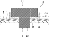
- FIG. 2 is a schematic cross-sectional view showing the configuration of a portion including a gasket of an electrochemical device.
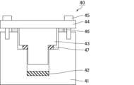
- FIG. 2 is a schematic cross-sectional view of a permeation test fixture used in a water vapor permeation test.
- the present disclosure provides a gasket for electrochemical devices (hereinafter also referred to as gasket (1) of the present disclosure) that contains polybutylene terephthalate (PBT) and has a compression rate of 5% or more when installed.
- gasket (1) of the present disclosure has the above-mentioned configuration and is therefore excellent in low water vapor permeability.
- gasket (1) of the present disclosure and gasket (2) of the present disclosure described below are collectively referred to as "gaskets of the present disclosure.”
- the gasket (1) of the present disclosure has a compression rate of 5% or more when fitted, and in terms of further improving low water vapor permeability, it is preferably 10% or more, more preferably 15% or more, even more preferably 20% or more, even more preferably 25% or more, even more preferably 30% or more, particularly preferably 40% or more, and is preferably less than 75%, more preferably 70% or less, even more preferably 65% or less, and even more preferably less than 65%.
- the compression ratio can be calculated by the following formula.
- Compression rate (%) [(thickness of gasket before compression) - (thickness of gasket in compressed state)] / (thickness of gasket before compression) x 100
- the cross section of the gasket in the installed and compressed state may be observed by X-ray photography, and the thickness of the gasket at the point where the distance between the faces of the part compressed by installation is the shortest may be regarded as the thickness of the gasket in its compressed state, and the thickness of the gasket at the point where the thickness is the thickest in the uncompressed part may be regarded as the thickness of the gasket before it is compressed.
- the thickness of the gasket after removal from the mounting state and heat treatment at 150° C. for 24 hours may be taken as the thickness of the gasket before it is compressed.
- the gasket (1) of the present disclosure has a compression ratio less than the rupture compression ratio, that is, the compression ratio during installation does not lead to compression rupture.
- the rupture compression ratio is determined as the compression ratio at the time of gasket rupture by conducting a compression test in accordance with JIS K7181:2011 using a circular gasket having a rectangular cross section with an outer diameter of 17.7 ⁇ 0.1 mm, an inner diameter of 14.2 ⁇ 0.1 mm, and a thickness of 1.6 ⁇ 0.05 mm (L 0 ).
- the gasket (1) of the present disclosure preferably has a water vapor permeability coefficient of 0.015 g/1000 hr or less, more preferably less than 0.010 g/1000 hr, even more preferably 0.009 g/1000 hr or less, even more preferably 0.008 g/1000 hr or less, even more preferably 0.007 g/1000 hr or less, even more preferably 0.006 g/1000 hr or less, particularly preferably 0.005 g/1000 hr or less, and may be 0.0001 g/1000 hr or more.
- the water vapor permeability coefficient is determined by measuring the mass of water that permeates a circular gasket having a rectangular cross section with an outer diameter of ⁇ 17.7 mm, an inner diameter of ⁇ 14.3 mm, and a thickness of 1.6 mmt under the above-mentioned compression ratio when mounted at 80°C for 1000 hours.
- the gasket (1) of the present disclosure may contain components other than PBT, but is preferably substantially made of PBT alone. This allows the effects of PBT to be exhibited significantly. "Substantially made of PBT alone” means that the content of PBT in the gasket is 95.0% by mass or more.
- the PBT content of the gasket is preferably 98.0 mass% or more, more preferably 99.0 mass% or more, even more preferably 99.5 mass% or more, particularly preferably 99.9 mass% or more, and most preferably 99.95 mass% or more. It is also preferred that the gasket (1) of the present disclosure consists solely of PBT.
- the present disclosure also provides a gasket for electrochemical devices (hereinafter also referred to as gasket (2) of the present disclosure) that contains a polymer and has a compression ratio of 20% or more and 75% or less when installed.
- gasket (2) of the present disclosure a gasket for electrochemical devices that contains a polymer and has a compression ratio of 20% or more and 75% or less when installed.
- the gasket (2) of the present disclosure has an excellent low water vapor permeability due to a compression ratio during installation of 20% or more and 75% or less.
- the compression ratio is preferably 25% or more, more preferably 30% or more, and even more preferably 40% or more, more preferably less than 75%, even more preferably 70% or less, even more preferably 65% or less, and particularly preferably less than 65%.
- the compression ratio can be calculated by the following formula.
- Compression rate (%) [(thickness of gasket before compression) - (thickness of gasket in compressed state)] / (thickness of gasket before compression) x 100
- the cross section of the gasket in the installed and compressed state may be observed by X-ray photography, and the thickness of the gasket at the point where the distance between the faces of the part compressed by installation is the shortest may be regarded as the thickness of the gasket in its compressed state, and the thickness of the gasket at the point where the thickness is the thickest in the uncompressed part may be regarded as the thickness of the gasket before it is compressed.
- the thickness of the gasket after removal from the mounting state and heat treatment at 150° C. for 24 hours may be taken as the thickness of the gasket before it is compressed.
- the gasket (2) of the present disclosure has a compression ratio less than the rupture compression ratio, that is, the compression ratio during installation does not lead to compression rupture.
- the rupture compression ratio is determined as the compression ratio at the time of gasket rupture by conducting a compression test in accordance with JIS K7181:2011 using a circular gasket having a rectangular cross section with an outer diameter of 17.7 ⁇ 0.1 mm, an inner diameter of 14.2 ⁇ 0.1 mm, and a thickness of 1.6 ⁇ 0.05 mm (L 0 ).
- the gasket (2) of the present disclosure preferably has a water vapor permeability coefficient of less than 0.010 g/1000 hr, more preferably 0.009 g/1000 hr or less, even more preferably 0.008 g/1000 hr or less, even more preferably 0.007 g/1000 hr or less, even more preferably 0.006 g/1000 hr or less, particularly preferably 0.005 g/1000 hr or less, and may be 0.0001 g/1000 hr or more.
- the water vapor permeability coefficient is determined by measuring the mass of water that permeates a circular gasket having a rectangular cross section with an outer diameter of ⁇ 17.7 mm, an inner diameter of ⁇ 14.3 mm, and a thickness of 1.6 mmt under the above-mentioned compression ratio when mounted at 80°C for 1000 hours.
- the gasket (2) of the present disclosure contains a polymer, and preferably contains a polymer with a fluorine substitution rate of 95% or less.
- a polymer with a low fluorine substitution rate has advantages such as low processing costs, ease of processing, and low specific gravity, but may have poor barrier properties against water vapor, etc.
- the gasket of the present disclosure has excellent low water vapor permeability even when it contains a polymer with a low fluorine substitution rate.
- the fluorine substitution rate of the polymer can be calculated by the following formula.
- Fluorine substitution rate (%) (number of fluorine atoms bonded to carbon atoms constituting the polymer)/((number of hydrogen atoms bonded to carbon atoms constituting the polymer)+(number of fluorine atoms and chlorine atoms bonded to carbon atoms constituting the polymer)) ⁇ 100
- the polymer with a fluorine substitution rate of 95% or less includes a fluoropolymer with a fluorine substitution rate of 95% or less and a non-fluorine polymer (fluorine substitution rate 0%), with a non-fluorine polymer being preferred.
- the fluorine substitution rate of the above fluoropolymer is preferably 90% or less, more preferably 70% or less, even more preferably 50% or less, and is preferably 10% or more, more preferably 20% or more.
- the above-mentioned fluoropolymers include, for example, ethylene [Et]/tetrafluoroethylene [TFE] copolymer [ETFE], Et/TFE/hexafluoropropylene [HFP] copolymer [EFEP], polychlorotrifluoroethylene [PCTFE], chlorotrifluoroethylene [CTFE]/TFE copolymer, CTFE/TFE/perfluoro(alkyl vinyl ether) [PAVE] copolymer, Et/CTFE copolymer, polyvinyl fluoride [PVF], polyvinylidene fluoride [PVdF], vinylidene fluoride [VdF]/TFE copolymer, VdF/HFP copolymer, and VdF/TFE/HFP.
- Et ethylene
- TFE tetrafluoroethylene
- EEFEP Et/TFE/hexafluoropropylene
- PCTFE polychlorotri
- Fluororesins such as copolymers, VdF/HFP/(meth)acrylic acid copolymers, VdF/CTFE copolymers, VdF/pentafluoropropylene copolymers, and VdF/PAVE/TFE copolymers; fluororubbers such as vinylidene fluoride [VdF]-based fluororubbers, tetrafluoroethylene [TFE]/propylene [Pr]-based fluororubbers, TFE/Pr/VdF-based fluororubbers, ethylene [Et]/hexafluoropropylene [HFP]-based fluororubbers, Et/HFP/VdF-based fluororubbers, Et/HFP/TFE-based fluororubbers, fluorosilicone-based fluororubbers, and fluorophosphazene-based fluororubbers.
- fluororubbers such as vinylidene fluoride [
- non-fluorine polymer examples include non-fluorine resins such as polyethylene (PE) such as ultra-high molecular weight polyethylene, polypropylene (PP), polybutylene terephthalate (PBT), and polyphenylene sulfide (PPS); non-fluorine rubbers such as nitrile rubber, hydrogenated nitrile rubber, styrene-butadiene rubber (SBR), chloroprene rubber (CR), butadiene rubber (BR), natural rubber (NR), isoprene rubber (IR), ethylene- ⁇ -olefin rubber, ethylene- ⁇ -olefin-non-conjugated diene rubber, chlorinated polyolefin rubber, chlorosulfonated polyolefin rubber, acrylic rubber, ethylene-based acrylic rubber, epichlorohydrin rubber, silicone rubber, butyl rubber (IIR), ethylene-vinyl ester rubber, and ethylene-methacrylate rubber; and crosslinked resins such as
- non-fluorinated resins are preferred, at least one selected from the group consisting of PE, PP, PBT and PPS is more preferred, and at least one selected from the group consisting of PE, PP and PBT is even more preferred.
- at least one selected from the group consisting of PP and PBT is preferred because of its excellent compression resistance. In terms of being more excellent in terms of low water vapor permeability, PE and PP are preferred, and PE is more preferred.
- ultra-high molecular weight PE examples include Mitsubishi Chemical Advanced Materials' Tiber UHMW-PE and Mitsui Chemicals' Hi-Zex Million.
- the gasket (2) of the present disclosure may contain components other than the above polymer, but is preferably substantially made of the above polymer. This allows the effects of the above polymer to be significantly exhibited. "Substantially made of the above polymer” means that the content of the above polymer is 95.0% by mass or more relative to the gasket.
- the content of the above polymer in the gasket is preferably 98.0 mass% or more, more preferably 99.0 mass% or more, even more preferably 99.5 mass% or more, particularly preferably 99.9 mass% or more, and most preferably 99.95 mass% or more. It is also preferred that the gasket (2) of the present disclosure consists solely of the above polymer.
- the gasket of the present disclosure can be manufactured by molding the raw polymer into a desired shape.
- the form of the raw polymer is not limited and may be a powder, pellet, dispersion, etc., but is preferably a powder or pellet.
- the method for molding the raw polymer is not particularly limited, and known molding methods such as cutting, injection molding, extrusion molding, and compression molding can be used.
- a rubber composition containing rubber and a crosslinking agent (and a crosslinking aid, if necessary) may be crosslinked and molded by a known method.
- the gasket disclosed herein is a component used in electrochemical devices to prevent leakage of liquid or gas or intrusion of liquid or gas from the outside.
- the shape of the gasket of the present disclosure is not particularly limited, and may be, for example, annular.
- the gasket of the present disclosure may have a shape such as a circle, an oval, or a rectangle with rounded corners in a plan view, and may have a through hole in the center.
- an electrochemical device 10 e.g., a sealed prismatic secondary battery
- an outer can not shown
- a lid 1.
- An electric element such as a power generator is housed inside the outer can, and the opening of the outer can is hermetically sealed by the lid 1.
- the lid 1 is provided with an external terminal 2 (positive terminal or negative terminal), and externally generated power is supplied to an electric element via the external terminal 2 for storage, and also supplied to an external load.
- a gasket 3 for sealing and insulation is provided between the external terminal 2 and the cover 1.
- the gasket 3 corresponds to the gasket of the present disclosure.
- an insulating plate 4 is provided on the lid 1 to electrically insulate the external terminal 2 from the lid 1 .
- the external terminal 2 has a terminal head 21 having a rectangular parallelepiped block shape and a cylindrical shaft portion 22. The shaft portion 22 protrudes from the lower surface of the terminal head 21 (on the inner side of the electrochemical device).
- the gasket 3 has a cylindrical portion 31, a flange portion 32 that extends radially from one opening of the cylindrical portion 31, and a side wall portion 33 that rises from the periphery of the flange portion 32.
- the cylindrical portion 31 is fitted onto the shaft portion 22 of the external terminal 2, and the inner peripheral surface of the cylindrical portion 31 abuts against the outer peripheral surface of the shaft portion 22.
- the cylindrical portion 31 is also inserted into the through hole of the lid 1, and the outer peripheral surface of the cylindrical portion 31 abuts against the inner peripheral surface of the through hole of the lid 1.
- the flange portion 32 is sandwiched between the lid 1 and the external terminal 2, with one contact surface of the flange portion 32 contacting the underside of the external terminal 2 and the other contact surface of the flange portion 32 contacting the surface of the lid 1.
- the gaskets of the present disclosure are used in electrochemical devices such as batteries and capacitors.
- the battery may be a secondary battery such as a lithium ion battery.
- the capacitor is not particularly limited, but is preferably an electrochemical capacitor.
- the electrochemical capacitor include an electric double layer capacitor, a hybrid capacitor, and a redox capacitor.
- the hybrid capacitor include a sodium ion capacitor, a lithium ion capacitor, and a magnesium ion capacitor. Among these, an electric double layer capacitor is particularly preferred.
- the gasket of the present disclosure can be suitably used as a gasket for batteries, and can be particularly suitably used as a gasket for secondary batteries such as lithium ion batteries.
- the secondary battery may be a secondary battery that uses an electrolyte solution, or may be a solid-state secondary battery.
- the solid-state secondary battery may be a secondary battery containing a solid electrolyte, and may be a semi-solid secondary battery containing a solid electrolyte and a liquid component as the electrolyte, or may be an all-solid-state secondary battery containing only a solid electrolyte as the electrolyte.
- the gasket of the present disclosure is preferably in contact with the electrolyte, i.e., has a contact surface with the electrolyte. Since the gasket of the present disclosure has excellent low water vapor permeability, when used in contact with the electrolyte, it can suppress the intrusion of water into the electrolyte.
- the electrolyte referred to here includes not only the electrolyte itself provided in the electrochemical device, but also a substance derived from the electrolyte, and may be a liquid, a solid, or a gas.
- the gas includes, for example, an electrolyte solution that has evaporated, or a gas generated by decomposition of the electrolyte solution during charging and discharging.
- the electrochemical device of the present disclosure preferably comprises a non-aqueous electrolyte. It is also preferable that the gasket of the present disclosure is used in contact with the non-aqueous electrolyte, i.e., has a surface that comes into contact with the non-aqueous electrolyte.
- the non-aqueous electrolyte can be prepared by dissolving a known electrolyte salt in a known organic solvent for dissolving electrolyte salts.
- the organic solvent for dissolving the electrolyte salt is not particularly limited, but one or more of the following can be used: known hydrocarbon solvents such as propylene carbonate, ethylene carbonate, butylene carbonate, ⁇ -butyrolactone, 1,2-dimethoxyethane, 1,2-diethoxyethane, dimethyl carbonate, diethyl carbonate, and ethyl methyl carbonate; and fluorine-based solvents such as fluoroethylene carbonate, fluoroether, and fluorinated carbonate.
- hydrocarbon solvents such as propylene carbonate, ethylene carbonate, butylene carbonate, ⁇ -butyrolactone, 1,2-dimethoxyethane, 1,2-diethoxyethane, dimethyl carbonate, diethyl carbonate, and ethyl methyl carbonate
- fluorine-based solvents such as fluoroethylene carbonate, fluoroether, and fluorinated carbonate.
- electrolyte salts examples include LiClO4, LiAsF6 , LiBF4 , LiPF6 , LiN( SO2CF3 ) 2 , LiN(SO2C2F5)2, LiCl, LiBr, CH3SO3Li, CF3SO3Li , cesium carbonate , etc. , and from the viewpoint of good cycle characteristics , LiPF6 , LiBF4 , LiN ( SO2CF3 ) 2 , LiN ( SO2C2F5 ) 2 , or combinations thereof are particularly preferred.
- the concentration of the electrolyte salt is preferably 0.8 mol/L or more, and more preferably 1.0 mol/L or more.
- the upper limit depends on the organic solvent used to dissolve the electrolyte salt, but is usually 1.5 mol/L.
- the solid electrolyte used in solid secondary batteries may be a sulfide-based solid electrolyte or an oxide-based solid electrolyte.
- sulfide-based solid electrolytes have the advantage of being flexible.
- the sulfide-based solid electrolyte preferably contains lithium.
- Sulfide-based solid electrolytes containing lithium are used in solid-state batteries that use lithium ions as a carrier, and are particularly preferred in terms of electrochemical devices with high energy density.
- the oxide-based solid electrolyte is preferably a compound that contains oxygen atoms (O), has the ionic conductivity of a metal belonging to Group 1 or 2 of the periodic table, and has electronic insulation properties.
- Ceramic materials in which elements have been substituted for LLZ are also known.
- Ceramic materials in which elements have been substituted for LLZ are also known.
- Li6.24La3Zr2Al0.24O11.98 Li6.25Al0.25La3Zr2O12 , Li6.6La3Zr1.6Ta0.4O12 , Li6.75La3Zr1.75Nb0.25O12 , etc. , in which LLZ is partially substituted with Al
- Li6.6La3Zr1.6Ta0.4O12 , Li6.75La3Zr1.75Nb0.25O12 , etc. in which LLZ is partially substituted with Ta, etc.
- LLZ -based ceramic materials in which at least one element of Mg (magnesium) and A (A is at least one element selected from the group consisting of Ca (calcium), Sr (strontium), and Ba (barium)) is substituted for LLZ can be mentioned.
- phosphorus compounds containing Li, P, and O are also desirable.
- the lithium phosphate include lithium phosphate (Li 3 PO 4 ), LiPON in which part of the oxygen in lithium phosphate is replaced with nitrogen, LiPOD 1 (D 1 is at least one selected from Ti, V, Cr, Mn, Fe, Co, Ni, Cu, Zr, Nb, Mo, Ru, Ag, Ta, W, Pt, Au, etc.), etc.
- LiA 1 ON is at least one selected from Si, B, Ge, Al, C, Ga, etc.
- Specific examples include Li 2 O-Al 2 O 3 -SiO 2 -P 2 O 5 -TiO 2 -GeO 2 , Li 2 O-Al 2 O 3 -SiO 2 -P 2 O 5 -TiO 2 , etc.
- the oxide-based solid electrolyte preferably contains lithium.
- the oxide-based solid electrolyte containing lithium is used in solid-state batteries that use lithium ions as a carrier, and is particularly preferred in that it is an electrochemical device having a high energy density.
- the oxide-based solid electrolyte is preferably an oxide having a crystalline structure.
- Oxides having a crystalline structure are particularly preferred in terms of good Li ion conductivity.
- Examples of oxides having a crystalline structure include perovskite type ( La0.51Li0.34TiO2.94 , etc. ), NASICON type ( Li1.3Al0.3Ti1.7 ( PO4 ) 3 , etc.), and garnet type ( Li7La3Zr2O12 ( LLZ ) , etc. ) . Among them, garnet type is preferred.
- An electrochemical device equipped with the gasket of the present disclosure is also part of the present disclosure.
- ⁇ Water vapor permeability test> As shown in Fig. 2, 2 g of water 42 was placed in an aluminum alloy cup 41. A gasket 47 was placed between the cup 41 and a gasket compression jig 43, and a lid 44 was fastened with a bolt 45 to compress the gasket 47. A spacer 46 was placed between the lid 44 and the cup 41, and the compression rate of the gasket 47 was adjusted to 12.5%, 37.5%, or 62.5%. The compression ratio was calculated from the following formula.
- Electrochemical device 1 Lid 2: External terminal 21: Terminal head 22: Shaft 3: Gasket 31: Cylindrical portion 32: Flange portion 33: Side wall 4: Insulating plate 40: Permeation test jig 41: Cup 42: Water 43: Gasket compression jig 44: Lid 45: Bolt 46: Spacer 47: Gasket
Landscapes
- Chemical & Material Sciences (AREA)
- Chemical Kinetics & Catalysis (AREA)
- Electrochemistry (AREA)
- General Chemical & Material Sciences (AREA)
- Engineering & Computer Science (AREA)
- Power Engineering (AREA)
- Microelectronics & Electronic Packaging (AREA)
- Sealing Battery Cases Or Jackets (AREA)
- Electric Double-Layer Capacitors Or The Like (AREA)
Abstract
L'invention concerne un joint d'étanchéité pour un dispositif électrochimique, ledit joint d'étanchéité ayant une excellente perméabilité à la vapeur d'eau faible, et un dispositif électrochimique l'utilisant. Le joint d'étanchéité pour un dispositif électrochimique contient du polybutylène téréphtalate et a un taux de compression égal ou supérieur à 5 % au moment du montage.
Applications Claiming Priority (2)
| Application Number | Priority Date | Filing Date | Title |
|---|---|---|---|
| JP2023-169987 | 2023-09-29 | ||
| JP2023169987 | 2023-09-29 |
Publications (1)
| Publication Number | Publication Date |
|---|---|
| WO2025070820A1 true WO2025070820A1 (fr) | 2025-04-03 |
Family
ID=95203860
Family Applications (1)
| Application Number | Title | Priority Date | Filing Date |
|---|---|---|---|
| PCT/JP2024/034984 Pending WO2025070820A1 (fr) | 2023-09-29 | 2024-09-30 | Joint d'étanchéité pour dispositif électrochimique et dispositif électrochimique |
Country Status (2)
| Country | Link |
|---|---|
| JP (1) | JP2025060571A (fr) |
| WO (1) | WO2025070820A1 (fr) |
Citations (4)
| Publication number | Priority date | Publication date | Assignee | Title |
|---|---|---|---|---|
| JP2010282824A (ja) * | 2009-06-04 | 2010-12-16 | Hitachi Vehicle Energy Ltd | 密閉型電池 |
| JP2020074290A (ja) * | 2014-07-24 | 2020-05-14 | パナソニックIpマネジメント株式会社 | 円筒型電池 |
| JP2022058294A (ja) * | 2020-09-30 | 2022-04-11 | ダイキン工業株式会社 | 蓄電体 |
| WO2022158864A2 (fr) * | 2021-01-19 | 2022-07-28 | 주식회사 엘지에너지솔루션 | Structure de fixation de borne d'électrode ainsi que batterie, bloc-batterie et véhicule la comprenant |
-
2024
- 2024-09-30 WO PCT/JP2024/034984 patent/WO2025070820A1/fr active Pending
- 2024-09-30 JP JP2024170719A patent/JP2025060571A/ja active Pending
Patent Citations (4)
| Publication number | Priority date | Publication date | Assignee | Title |
|---|---|---|---|---|
| JP2010282824A (ja) * | 2009-06-04 | 2010-12-16 | Hitachi Vehicle Energy Ltd | 密閉型電池 |
| JP2020074290A (ja) * | 2014-07-24 | 2020-05-14 | パナソニックIpマネジメント株式会社 | 円筒型電池 |
| JP2022058294A (ja) * | 2020-09-30 | 2022-04-11 | ダイキン工業株式会社 | 蓄電体 |
| WO2022158864A2 (fr) * | 2021-01-19 | 2022-07-28 | 주식회사 엘지에너지솔루션 | Structure de fixation de borne d'électrode ainsi que batterie, bloc-batterie et véhicule la comprenant |
Also Published As
| Publication number | Publication date |
|---|---|
| JP2025060571A (ja) | 2025-04-10 |
Similar Documents
| Publication | Publication Date | Title |
|---|---|---|
| KR100990003B1 (ko) | 고에너지 재충전식 리튬 배터리 | |
| US8088515B2 (en) | Electrode and lithium-ion secondary battery | |
| US20080241655A1 (en) | Electrode and electrochemical device | |
| JP6596826B2 (ja) | 電極及び非水電解質二次電池 | |
| TWI482340B (zh) | 鋰二次電池的電極模組 | |
| CN1164001C (zh) | 无水电解质电池 | |
| US20230361391A1 (en) | Cylindrical non-aqueous electrolyte secondary cell | |
| JP2021512465A (ja) | 二次電池用電解液、これを含むバッテリーおよびフレキシブルバッテリー | |
| US12068485B2 (en) | Secondary battery | |
| JPH09251862A (ja) | 有機電解液二次電池 | |
| WO2025070820A1 (fr) | Joint d'étanchéité pour dispositif électrochimique et dispositif électrochimique | |
| US20190252662A1 (en) | Nonaqueous electrolyte secondary battery | |
| JP2009021040A (ja) | 電池用非水電解液及びそれを備えた非水電解液電池 | |
| WO2024111323A1 (fr) | Batterie secondaire | |
| JP7733341B2 (ja) | 電気化学デバイス用絶縁部材 | |
| JP5407347B2 (ja) | リチウム一次電池 | |
| CN122003763A (zh) | 电化学器件用垫片以及电化学器件 | |
| JP7688310B2 (ja) | ガスケット、及び、電気化学デバイス | |
| US20240339727A1 (en) | Non-aqueous electrolyte secondary battery | |
| JP7721526B2 (ja) | 非水電解質二次電池用セパレータ及び非水電解質二次電池 | |
| JPH11283599A (ja) | リチウムイオン電池 | |
| JP2005174833A (ja) | 非水電解質二次電池 | |
| WO2020166189A1 (fr) | Électrode positive et batterie secondaire | |
| JP2001229888A (ja) | 薄型電池 | |
| JP2018166054A (ja) | 正極およびこれを用いたリチウムイオン二次電池 |
Legal Events
| Date | Code | Title | Description |
|---|---|---|---|
| 121 | Ep: the epo has been informed by wipo that ep was designated in this application |
Ref document number: 24872599 Country of ref document: EP Kind code of ref document: A1 |