WO2025105019A1 - リング状部材の加工装置および加工方法、軸受の製造方法、機械装置の製造方法、ならびに、車両の製造方法 - Google Patents
リング状部材の加工装置および加工方法、軸受の製造方法、機械装置の製造方法、ならびに、車両の製造方法 Download PDFInfo
- Publication number
- WO2025105019A1 WO2025105019A1 PCT/JP2024/031579 JP2024031579W WO2025105019A1 WO 2025105019 A1 WO2025105019 A1 WO 2025105019A1 JP 2024031579 W JP2024031579 W JP 2024031579W WO 2025105019 A1 WO2025105019 A1 WO 2025105019A1
- Authority
- WO
- WIPO (PCT)
- Prior art keywords
- ring
- shaped member
- peripheral surface
- circumferential
- support
- Prior art date
- Legal status (The legal status is an assumption and is not a legal conclusion. Google has not performed a legal analysis and makes no representation as to the accuracy of the status listed.)
- Pending
Links
Images




Classifications
-
- F—MECHANICAL ENGINEERING; LIGHTING; HEATING; WEAPONS; BLASTING
- F16—ENGINEERING ELEMENTS AND UNITS; GENERAL MEASURES FOR PRODUCING AND MAINTAINING EFFECTIVE FUNCTIONING OF MACHINES OR INSTALLATIONS; THERMAL INSULATION IN GENERAL
- F16C—SHAFTS; FLEXIBLE SHAFTS; ELEMENTS OR CRANKSHAFT MECHANISMS; ROTARY BODIES OTHER THAN GEARING ELEMENTS; BEARINGS
- F16C33/00—Parts of bearings; Special methods for making bearings or parts thereof
- F16C33/30—Parts of ball or roller bearings
- F16C33/58—Raceways; Race rings
- F16C33/64—Special methods of manufacture
-
- B—PERFORMING OPERATIONS; TRANSPORTING
- B24—GRINDING; POLISHING
- B24B—MACHINES, DEVICES, OR PROCESSES FOR GRINDING OR POLISHING; DRESSING OR CONDITIONING OF ABRADING SURFACES; FEEDING OF GRINDING, POLISHING, OR LAPPING AGENTS
- B24B19/00—Single-purpose machines or devices for particular grinding operations not covered by any other main group
- B24B19/02—Single-purpose machines or devices for particular grinding operations not covered by any other main group for grinding grooves, e.g. on shafts, in casings, in tubes, homokinetic joint elements
- B24B19/06—Single-purpose machines or devices for particular grinding operations not covered by any other main group for grinding grooves, e.g. on shafts, in casings, in tubes, homokinetic joint elements for grinding races, e.g. roller races
-
- B—PERFORMING OPERATIONS; TRANSPORTING
- B24—GRINDING; POLISHING
- B24B—MACHINES, DEVICES, OR PROCESSES FOR GRINDING OR POLISHING; DRESSING OR CONDITIONING OF ABRADING SURFACES; FEEDING OF GRINDING, POLISHING, OR LAPPING AGENTS
- B24B41/00—Component parts such as frames, beds, carriages, headstocks
- B24B41/06—Work supports, e.g. adjustable steadies
- B24B41/067—Work supports, e.g. adjustable steadies radially supporting workpieces
-
- F—MECHANICAL ENGINEERING; LIGHTING; HEATING; WEAPONS; BLASTING
- F16—ENGINEERING ELEMENTS AND UNITS; GENERAL MEASURES FOR PRODUCING AND MAINTAINING EFFECTIVE FUNCTIONING OF MACHINES OR INSTALLATIONS; THERMAL INSULATION IN GENERAL
- F16C—SHAFTS; FLEXIBLE SHAFTS; ELEMENTS OR CRANKSHAFT MECHANISMS; ROTARY BODIES OTHER THAN GEARING ELEMENTS; BEARINGS
- F16C19/00—Bearings with rolling contact, for exclusively rotary movement
- F16C19/52—Bearings with rolling contact, for exclusively rotary movement with devices affected by abnormal or undesired conditions
-
- F—MECHANICAL ENGINEERING; LIGHTING; HEATING; WEAPONS; BLASTING
- F16—ENGINEERING ELEMENTS AND UNITS; GENERAL MEASURES FOR PRODUCING AND MAINTAINING EFFECTIVE FUNCTIONING OF MACHINES OR INSTALLATIONS; THERMAL INSULATION IN GENERAL
- F16C—SHAFTS; FLEXIBLE SHAFTS; ELEMENTS OR CRANKSHAFT MECHANISMS; ROTARY BODIES OTHER THAN GEARING ELEMENTS; BEARINGS
- F16C33/00—Parts of bearings; Special methods for making bearings or parts thereof
- F16C33/30—Parts of ball or roller bearings
- F16C33/58—Raceways; Race rings
- F16C33/62—Selection of substances
-
- F—MECHANICAL ENGINEERING; LIGHTING; HEATING; WEAPONS; BLASTING
- F16—ENGINEERING ELEMENTS AND UNITS; GENERAL MEASURES FOR PRODUCING AND MAINTAINING EFFECTIVE FUNCTIONING OF MACHINES OR INSTALLATIONS; THERMAL INSULATION IN GENERAL
- F16C—SHAFTS; FLEXIBLE SHAFTS; ELEMENTS OR CRANKSHAFT MECHANISMS; ROTARY BODIES OTHER THAN GEARING ELEMENTS; BEARINGS
- F16C41/00—Other accessories, e.g. devices integrated in the bearing not relating to the bearing function as such
- F16C41/04—Preventing damage to bearings during storage or transport thereof or when otherwise out of use
-
- F—MECHANICAL ENGINEERING; LIGHTING; HEATING; WEAPONS; BLASTING
- F16—ENGINEERING ELEMENTS AND UNITS; GENERAL MEASURES FOR PRODUCING AND MAINTAINING EFFECTIVE FUNCTIONING OF MACHINES OR INSTALLATIONS; THERMAL INSULATION IN GENERAL
- F16C—SHAFTS; FLEXIBLE SHAFTS; ELEMENTS OR CRANKSHAFT MECHANISMS; ROTARY BODIES OTHER THAN GEARING ELEMENTS; BEARINGS
- F16C2220/00—Shaping
- F16C2220/60—Shaping by removing material, e.g. machining
-
- F—MECHANICAL ENGINEERING; LIGHTING; HEATING; WEAPONS; BLASTING
- F16—ENGINEERING ELEMENTS AND UNITS; GENERAL MEASURES FOR PRODUCING AND MAINTAINING EFFECTIVE FUNCTIONING OF MACHINES OR INSTALLATIONS; THERMAL INSULATION IN GENERAL
- F16C—SHAFTS; FLEXIBLE SHAFTS; ELEMENTS OR CRANKSHAFT MECHANISMS; ROTARY BODIES OTHER THAN GEARING ELEMENTS; BEARINGS
- F16C2220/00—Shaping
- F16C2220/60—Shaping by removing material, e.g. machining
- F16C2220/70—Shaping by removing material, e.g. machining by grinding
Definitions
- the present disclosure relates to a processing device for processing the outer peripheral surface of a metal ring-shaped member.
- the outer surfaces of metal ring-shaped components are ground to improve surface precision and surface roughness.
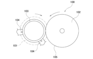
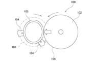
- FIG 13 shows a conventional grinding device 100 described in Patent Document 1 (JP Patent Publication 2004-195651).
- the grinding device 100 is equipped with a backing plate 101 that can be rotated around its own central axis, a grindstone 102 that has a central axis arranged parallel to the central axis of the backing plate 101 and can be rotated around said central axis, and two shoes 104 for radially positioning a metal ring-shaped member 103, which is the workpiece (object to be processed).
- the axial end face of the ring-shaped member 103 is magnetically attracted to the tip surface of the backing plate 101, and the tips (seat surfaces) of the two shoes 104 are brought into sliding contact with the outer peripheral surface of the ring-shaped member 103, thereby positioning the ring-shaped member 103 radially.
- the backing plate 101 is rotated to rotate the ring-shaped member 103, and the grinding surface 105, which is the outer peripheral surface of the rotating grinding wheel 102, is pressed against a portion of the outer peripheral surface of the ring-shaped member 103 that is circumferentially away from the portion where the tips of the two shoes 104 are in sliding contact, thereby grinding the outer peripheral surface of the ring-shaped member 103.
- the ring-shaped member 103 elastically deforms into an ellipse, that is, if the outer peripheral surface of the ring-shaped member 103 elastically deforms so as to escape from the grinding surface 105 of the grinding wheel 102, the amount of grinding of the outer peripheral surface of the ring-shaped member 103 and the amount of cutting into the grinding wheel 102 will not match, which may make it difficult to finish the outer peripheral surface of the ring-shaped member 103 to the desired diameter dimension.
- Patent Document 2 JP Patent Publication 2019-42864A describes a grinding device in which a portion of the outer circumferential surface of a ring-shaped member that is circumferentially removed from the portion to be ground by a grindstone is supported by two shoes, and when the outer circumferential surface of the ring-shaped portion is ground by a grindstone, a moment is applied to the ring-shaped member in a direction that presses the outer circumferential surface of the ring-shaped member toward the first shoe of the two shoes that is closer to the grindstone.
- the second shoe that is the farthest from the grindstone is supported so that it can oscillate about an oscillating axis that is located farther from the first shoe than the circumferential center of the second shoe. Therefore, as the grindstone is pressed against the outer circumferential surface of the ring-shaped member, the reaction force applied from the second shoe to the ring-shaped member is greater at the contact point between the ring-shaped member and the second shoe on the side farther from the first shoe than on the side closer to the first shoe. As a result, a moment is applied to the ring-shaped member in a direction that presses the outer circumferential surface towards the first shoe.
- the grinding device described in Patent Document 2 presses the grinding surface of the grindstone against the outer peripheral surface of the ring-shaped member, effectively preventing a decrease in the contact pressure between the first shoe and the outer peripheral surface of the ring-shaped member, even if the ring-shaped member elastically deforms into an elliptical shape, and thus stabilizing the position of the ring-shaped member during grinding.
- the outer peripheral surface of the ring-shaped member is supported by two shoes, so it is difficult to prevent the ring-shaped member from elastically deforming into an elliptical shape due to the pressing force of the grindstone.
- the amount of grinding on the outer peripheral surface of the ring-shaped member and the amount of cutting into the grinding wheel do not match, which can make it difficult to finish the outer peripheral surface of the ring-shaped member to the desired diameter dimension.
- the objective of this aspect of the present invention is to provide a processing device and processing method for ring-shaped components that are advantageous for improving quality.
- a processing device for a ring-shaped member includes a rotary drive mechanism that rotates a metal ring-shaped member in a circumferential direction around a reference axis, a grinding mechanism having a grinding wheel that is pressed against the outer peripheral surface of the ring-shaped member, and a support mechanism that has a support part that contacts the inner peripheral surface of the ring-shaped member in at least one circumferential range around the reference axis and supports the ring-shaped member.
- a method for machining a ring-shaped member includes the steps of rotating a metal ring-shaped member in a circumferential direction around a reference axis, and pressing a grinding wheel against the outer peripheral surface of the ring-shaped member, and supporting the ring-shaped member by contacting a support portion with the inner peripheral surface of the ring-shaped member in at least one circumferential range around the reference axis.
- a method for manufacturing a bearing including a ring-shaped member includes a step of machining the outer circumferential surface of the ring-shaped member using the method for machining a ring-shaped member of the above aspect.
- a method for manufacturing a mechanical device includes a step of manufacturing a mechanical part using the bearing manufacturing method of the above aspect, and a step of attaching the mechanical part to the device body.
- a method for manufacturing a vehicle includes a step of manufacturing a bearing using the method for manufacturing a bearing of the above aspect, and a step of attaching the bearing to a vehicle body.
- a processing device and processing method for ring-shaped components are provided that are advantageous for improving quality.
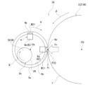
- FIG. 1 is a side view that illustrates a schematic diagram of a processing apparatus for a ring-shaped member according to a first embodiment.
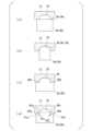
- FIG. 2 is a diagram showing a schematic diagram of the support structure.
- FIG. 3 is a cross-sectional view of a mechanical device including a rolling bearing.
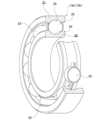
- FIG. 4 is a partially cutaway perspective view of the rolling bearing.
- FIG. 5 is a schematic cross-sectional view showing a bearing having a coating film.
- FIG. 6 is a diagram showing a schematic example of a support portion (support member) set relative to the outer ring.
- FIG. 7 is a side view that illustrates a schematic diagram of a processing device for a ring-shaped member according to the second embodiment.
- FIG. 1 is a side view that illustrates a schematic diagram of a processing apparatus for a ring-shaped member according to a first embodiment.
- FIG. 2 is a diagram showing a schematic diagram of the support structure.
- FIG. 3 is a cross-section
- FIG. 8 is a side view that illustrates a schematic diagram of a processing device for a ring-shaped member according to the third embodiment.
- FIG. 9 is a side view that illustrates a schematic diagram of a processing device for a ring-shaped member according to the fourth embodiment.
- FIG. 10 is a side view that illustrates a schematic diagram of a processing apparatus for a ring-shaped member according to the fifth embodiment.
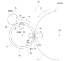
- FIG. 11 is a side view that illustrates a schematic diagram of a processing apparatus for a ring-shaped member according to the sixth embodiment.
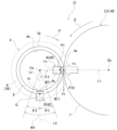
- FIG. 12 is a side view that illustrates a schematic diagram of a processing apparatus for a ring-shaped member according to the seventh embodiment.
- FIG. 13 is a side view showing a schematic diagram of an example of a conventional structure of a processing device for a ring-shaped member.
- FIG. 14 is an exaggerated view showing the state in which the ring-shaped member is elastically deformed into an elliptical shape.
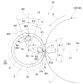
- the processing device 1 for the ring-shaped member includes a rotation drive mechanism 2, a grinding mechanism 40, and a support mechanism 4.
- the processing device 1 is a grinding device for performing grinding processing.
- the processing device 1 can be a super-finishing device for performing super-finishing processing.
- the rotary drive mechanism 2 is capable of rotating the metal ring-shaped member 5, which is the workpiece, in a predetermined direction ⁇ (clockwise in FIG. 1).
- the rotary drive mechanism 2 rotates the ring-shaped member 5 in the circumferential direction around the reference axis (Oa).
- the rotation drive mechanism 2 has a holding member 6 that holds the ring-shaped member 5, and a drive unit 36.
- the rotation drive mechanism 2 has a backing plate (holding member, plate member) 6 that rotates the ring-shaped member 5 while magnetically adsorbing the axial end face of the ring-shaped member 5.
- the backing plate 6 holds the ring-shaped member 5 by magnetic adsorption.
- the drive unit 36 rotates the ring-shaped member 5 via the backing plate (holding member) 6.
- the holding member 6 can have a structure different from the backing plate.
- the backing plate 6 can be rotated around a central axis (reference axis, rotation axis) Oa.
- the central axis Oa of the backing plate 6 is arranged along the horizontal direction (the front-to-back direction of the paper in FIG. 1).
- the central axis of the backing plate can be arranged in a direction other than the horizontal direction.
- the backing plate 6 has a tip surface (the end surface facing the front side of the paper in FIG. 1, the holding surface) that includes a flat surface perpendicular to the central axis Oa.
- the backing plate 6 is capable of supporting the ring-shaped member 5 coaxially with itself by magnetically attracting the axial end surface (the end surface facing the rear side of the paper in FIG. 1, the axial end surface) of the ring-shaped member 5 to the tip surface.
- the grinding mechanism 40 has a grinding wheel 3 and a drive unit 37.
- the grinding wheel 3 can be pressed against the outer peripheral surface 5a of the ring-shaped member 5 in order to perform grinding processing on the outer peripheral surface 5a of the ring-shaped member 5.
- the grinding wheel 3 is rotated by the drive unit 37.
- the grinding wheel 3 has a grinding surface 7 on its outer circumferential surface, and is configured as a rotating grinding wheel that can be rotated around a central axis (rotation axis) Ob arranged parallel to the central axis Oa of the backing plate 6.
- the grinding surface 7 has a generatrice shape that matches the generatrice shape of the outer circumferential surface 5a of the ring-shaped member 5, which is the surface to be ground.
- the grinding wheel 3 can be rotated around the central axis Ob in a direction ⁇ (counterclockwise in FIG.
- the rotation direction and rotation speed of the grinding wheel 3 and the rotation direction and rotation speed of the ring-shaped member 5 can be set arbitrarily.
- the grinding wheel 3 can move its central axis Ob toward or away from the central axis Oa of the backing plate 6, i.e., it can move left and right in FIG. 1.
- the grinding surface 7 of the grinding wheel 3 can be pressed against the outer peripheral surface 5a of the ring-shaped member 5 supported by the backing plate 6.
- the grinding mechanism 40 can be configured so that the grinding wheel 3 does not substantially rotate.
- the processing device is a super-finishing device, when performing super-finishing processing on the outer peripheral surface 5a of the ring-shaped member 5, it is possible to rotate only the ring-shaped member 5 and oscillate the grinding wheel without rotating it.
- the support mechanism 4 has a support portion 42 that contacts the inner peripheral surface 5b of the ring-shaped member 5 in at least one circumferential range (W11, W21) around the reference axis (Oa).
- the support portion 42 has inner diameter side support members 8a, 8b that contact the inner peripheral surface 5b of the ring-shaped member 5 and support the ring-shaped member 5 in the radial direction. Additionally, it may have an outer diameter side support member that contacts the outer peripheral surface 5a of the ring-shaped member 5 and supports the ring-shaped member 5 in the radial direction.
- the support portion 42 has inner diameter side support members 8a, 8b and does not have an outer diameter side support member.
- the support portion 42 has two inner diameter side support members 8a, 8b. In other examples, the support portion 42 can have one inner diameter side support member or three or more inner diameter side support members.
- the support members 8a and 8b are arranged spaced apart from each other in the circumferential direction.
- the support members 8a and 8b are in contact with the inner peripheral surface 5b of the ring-shaped member 5 and have seating surfaces (tip surfaces, support surfaces, contact surfaces) 9a and 9b that support the ring-shaped member 5.
- At least a portion of the seating surfaces 9a and 9b has a curved shape corresponding to the curved shape of the inner peripheral surface 5b of the ring-shaped member 5.
- the support parts 42 (support members 8a and 8b) do not substantially move in the circumferential direction, and the circumferential positions (circumferential positions around the reference axis Oa) of the support members 8a and 8b are constant.
- the inner peripheral surface 5b of the ring-shaped member 5 moves in the circumferential direction relative to the support parts 42 (seat surfaces 9a and 9b of the support members 8a and 8b).
- the seating surfaces 9a and 9b slide against the inner peripheral surface 5b of the ring-shaped member 5.
- the two inner diameter side support members 8a, 8b each have a shoe that slides against the inner peripheral surface 5b of the ring-shaped member 5.
- the shoe can be made of a hard material with excellent wear resistance, such as cemented carbide, ceramics, or diamond.
- the two inner diameter support members 8a and 8b are supported and fixed to a support base (frame, housing) (not shown) that constitutes the support mechanism 4.
- a holding member (backing plate) 6 for holding the ring-shaped member 5 is attached to a frame body 50.
- the support members 8a, 8b that contact the inner peripheral surface 5b of the ring-shaped member 5 are also attached to the frame body 50. That is, the holding member 6 and the support member 8a (8b) are attached to a common frame body 50.
- the holding member 6 is supported by the frame body 50 so as to be rotatable around the reference axis Oa.
- the support member 8a (8b) is supported by the frame body 50 via an adjustment mechanism 51.
- the adjustment mechanism 51 can adjust the position (position of the seat surface 9a (9b) in a plane intersecting the reference axis Oa) and/or the attitude of the support member 8a (8b) relative to the reference axis Oa.
- the adjustment mechanism 51 has a linear motion mechanism and/or an eccentric mechanism.
- the holding member 6 and the support member 8a (8b) are positioned relative to the common reference axis Oa. Such a configuration is advantageous for simplifying the adjustment work and improving the positional accuracy.
- both axial ends of the support member 8a (8b) are supported by the frame body 50 (part (a) of FIG. 2).
- the double-sided support structure is advantageous for ensuring high rigidity.
- the support member 8a (8b) is detachable from the frame body 50.
- one axial end of the support member 8a (8b) is supported by the frame body 50 (parts (b) and (c) of FIG. 2).
- the single-sided support structure is advantageous for facilitating the attachment and detachment of the ring-shaped member 5.
- the support member 8a (8b) is supported on the same side as the side on which the retaining member 6 is supported (part (b) of FIG. 2).
- This structure is advantageous for saving space.
- the support member 8a (8b) is supported on the side opposite to the side on which the retaining member 6 is supported. This structure is advantageous in facilitating adjustment of the support members 8a (8b).
- a plurality of support members 8a, 8b are held in one housing 53 provided with an adjustment mechanism 51.
- the housing 53 holding the plurality of support members 8a, 8b is attached to a frame body 50.
- the plurality of support members 8a, 8b are simultaneously set to the frame body 50 or simultaneously removed via the housing 53.
- the housing 53 can be configured to be separable in the axial direction.
- the housing 53 has a first part and a second part, and the first part and the second part can be combined with each other in the axial direction.
- the first part of the housing 53 supports the first axial end of the support member 8a (8b), and the second part of the housing 53 supports the second axial end of the support member 8a (8b).
- the separated structure is advantageous for ensuring high rigidity and facilitating attachment and detachment operations.
- each of the inner diameter side support members 8a, 8b has a tip surface (seat surface, support surface, contact surface) 9a, 9b that slides against the inner peripheral surface 5b of the ring-shaped member 5.
- each of the tip surfaces 9a, 9b is configured as a partial cylindrical surface curved along the inner peripheral surface 5b of the ring-shaped member 5.
- the radius of curvature of each of the tip surfaces 9a, 9b is substantially the same as the radius of curvature of the inner peripheral surface 5b of the ring-shaped member 5.
- each of the tip surfaces 9a, 9b is in surface contact with the inner peripheral surface 5b of the ring-shaped member 5.
- the tip portion (seat surface) of the inner diameter side support member 8a (8b), which is a shoe can be in line contact or point contact with the inner peripheral surface 5b of the ring-shaped member 5.
- the circumferential positions of the seating surfaces 9a, 9b of the support members 8a, 8b are set according to the grinding position, etc.
- the circumferential range (W11) which is the support range of the first support member 8a includes the circumferential position corresponding to the contact position (rear side position) between the grinding wheel 3 and the ring-shaped member 5.
- the support position (P1) of the first support member 8a on the inner peripheral surface 5b and the contact position (P10) of the grinding wheel 3 and the ring-shaped member 5 on the outer peripheral surface 5a are located on or near a straight line (L1) extending radially of the ring-shaped member 5.
- the support position (P1) and the contact position (P10) are essentially on the front and back of the wall of the ring-shaped member 5.
- the first support member 8a receives the radially inward force from the grinding wheel 3 acting on the outer peripheral surface 5a of the ring-shaped member 5 on its inner inner peripheral surface 5b.
- the ring-shaped member 5 is supported by the support portion 42 at or near the circumferential position substantially the same as the circumferential position where the pressing force of the grinding wheel 3 acts. Changes in the shape of the ring-shaped member 5 are suppressed during the grinding process.
- the circumferential range (W21) of the second support member 8b includes a circumferential position on a vertical line passing through the reference axis (Oa) and above the reference axis (Oa).
- the multiple support members 8a, 8b can be arranged in other ways.
- the circumferential center positions P1, P2 of the portions of the two inner diameter side support members 8a, 8b adjacent to each other in the circumferential direction of the ring-shaped member 5 that contact the inner peripheral surface 5b of the ring-shaped member 5 can be positioned apart from each other by ⁇ 1 when expressed as a central angle centered on the central axis Oa of the ring-shaped member 5.
- the angle formed by one imaginary straight line La connecting the circumferential center position P1 of the tip surface 9a, which is the portion of one inner diameter side support member 8a that contacts the inner peripheral surface 5b of the ring-shaped member 5, and the central axis Oa of the ring-shaped member 5, and the other imaginary straight line Lb connecting the circumferential center position P2 of the tip surface 9b, which is the portion of the other inner diameter side support member 8b that contacts the inner peripheral surface 5b of the ring-shaped member 5, and the central axis Oa of the ring-shaped member 5, can be ⁇ 1.
- the inner diameter side support member 8a has a first support range (first contact range) W11, and the inner diameter side support member 8a has a second support range (second contact range) W21.
- the angle (central angle around the reference axis) ⁇ 1 between the circumferential center position of the first support range W11 and the circumferential center position of the second support range W21 is appropriately set.
- ⁇ 1 can be 20° or more and 160° or less, 75° or more and 105° or less, or 75° or more and 90° or less. In the example of FIG. 1, ⁇ 1 is 90°.
- the above values are merely examples and are not limited to these.
- the circumferential position and shape of one of the inner diameter side support members 8a are regulated so that at least a part of the tip surface 9a, which is the portion of one of the inner diameter side support members 8a that contacts the inner peripheral surface 5b of the ring-shaped member 5, is in a first circumferential range W1 in which the central angle centered on the central axis Oa of the ring-shaped member 5 is in the range of ⁇ 1, based on a first virtual straight line L1 connecting the central axis Oa of the ring-shaped member 5 and the central axis Ob of the grinding wheel 3, when viewed from the axial direction of the ring-shaped member 5.
- the support member 8a has an area (seat surface (support surface, contact surface) 9a) that can contact the inner peripheral surface 5b of the ring-shaped member 5, and the circumferential range (central angle) W1 corresponding to that area (the circumferential length of the seat surface 9a) is appropriately set.
- ⁇ 1 is 45°, 22.5°, or 15°.
- ⁇ 1 can be approximately 60, 55, 50, 45, 40, 35, 30, 25, 20, 15, 10, or 5°. The above values are examples and are not limited to these.
- the circumferential position and shape of the tip surface 9a of one of the inner diameter side support members 8a are regulated so that the entire portion of the tip surface 9a of the one of the inner diameter side support members 8a that contacts the inner peripheral surface 5b of the ring-shaped member 5 is within the first circumferential range W1.
- the angle between the first virtual straight line L1 and the other virtual straight line La can be -22.5° to +22.5°, or -15° to +15°, assuming that the direction of rotation ⁇ of the ring-shaped member 5 is positive.
- the angle between the first virtual straight line L1 and the other virtual straight line La is 0°, and the circumferential center position P1 of the tip surface 9a of one of the inner diameter side support members 8a is located on the first virtual straight line L1.
- only a portion of the portion where the inner diameter side support member 8a contacts the inner peripheral surface 5b of the ring-shaped member 5 can be in the first circumferential range W1.
- the circumferential center position P1 can be located at a circumferential position different from the first virtual straight line L1.
- the circumferential position and shape of the other inner diameter side support member 8b are regulated so that at least a part of the tip surface 9b, which is a portion of the other inner diameter side support member 8b that contacts the inner peripheral surface 5b of the ring-shaped member 5, is in a second circumferential range W2 in which the central angle around the central axis Oa of the ring-shaped member 5 is in the range of ⁇ 2, based on a second imaginary line L2 that extends from the central axis Oa of the ring-shaped member 5 in a direction shifted by 90° in the opposite direction ⁇ to the rotation direction ⁇ of the ring-shaped member 5 with respect to the first imaginary line L1.
- the support member 8b has an area (seat surface (support surface, contact surface) 9b) that can contact the inner peripheral surface 5b of the ring-shaped member 5, and the circumferential range (central angle) W2 corresponding to that area (circumferential length of the seat surface 9b) is appropriately set.
- ⁇ 2 is 45° or 22.5°.
- ⁇ 2 can be approximately 60, 55, 50, 45, 40, 35, 30, 25, 20, 15, 10, or 5°. The above values are examples and are not limited to these.
- the second virtual straight line L2 can be a straight line extending from the central axis of the ring-shaped member in a direction shifted by 90° from the first virtual straight line L1 in the rotation direction of the ring-shaped member 5.
- the circumferential position and shape of the tip surface 9b of the other inner diameter side support member 8b are regulated so that the entire portion of the tip surface 9b of the other inner diameter side support member 8b that contacts the inner circumferential surface 5b of the ring-shaped member 5 is within the second circumferential range W2.
- the angle between the second imaginary straight line L2 and the other imaginary straight line Lb can be -45° to +45°, 0° to +45°, or 0° to +15°, assuming that the direction of rotation ⁇ of the ring-shaped member 5 is positive.
- the angle between the second imaginary straight line L2 and the other imaginary straight line Lb is 0°, and the circumferential center position P2 of the tip surface 9a of the other inner diameter side support member 8a is located on the second imaginary straight line L2.
- only a portion of the portion where the inner diameter side support member 8b contacts the inner circumferential surface 5b of the ring-shaped member 5 can be in the second circumferential range W2.
- the circumferential center position P2 can be located at a circumferential position different from the second imaginary straight line L2.
- the axial end surface of the ring-shaped member 5 is held by the backing plate 6 through magnetic attraction.
- the backing plate 6 rotates in a predetermined direction ⁇ .
- the ring-shaped member 5 rotates in a predetermined direction ⁇ around the central axis Oa.
- the tip surfaces 9a, 9b of the two inner diameter side support members 8a, 8b are in sliding contact with the inner peripheral surface 5b of the ring-shaped member 5.
- the ring-shaped member 5 is supported in the radial direction by the two inner diameter side support members 8a, 8b.
- the grinding wheel 3 rotates around the central axis Ob in the direction ⁇ opposite to the specified direction ⁇ .
- the circumferential speed of the grinding surface 7 is faster than the circumferential speed of the outer peripheral surface 5a of the ring-shaped member 5.
- the grinding surface 7 is pressed against the outer peripheral surface 5a of the ring-shaped member 5, and the outer peripheral surface 5a is subjected to grinding.
- a specified fluid such as coolant is supplied during the grinding process.
- the inner diameter side support members (two inner diameter side support members 8a, 8b) constituting the support mechanism 4 can be provided with a coolant supply hole having an opening. The coolant discharged from the opening of the coolant supply hole is supplied to the contact area between the outer circumferential surface 5a of the ring-shaped member 5 and the grinding surface 7 of the grinding wheel 3.
- the inner peripheral surface 5b of the ring-shaped member 5 is supported by the inner diameter side support members (two inner diameter side support members 8a, 8b) of the support mechanism 4. This suppresses changes in the shape of the ring-shaped member 5 during the grinding process.
- the rigidity against the processing force applied from the grinding surface 7 of the grinding wheel 3 to the outer peripheral surface 5a of the ring-shaped member 5 is improved compared to the conventional case.
- the circumferential center positions P1, P2 of the two inner diameter side support members 8a, 8b adjacent to each other in the circumferential direction of the ring-shaped member 5, which contact the inner peripheral surface 5b of the ring-shaped member 5, are arranged apart from each other by ⁇ 1 when expressed as a central angle centered on the central axis Oa of the ring-shaped member 5. This makes it possible to efficiently improve the rigidity of the ring-shaped member 5 against elastic deformation in the radial direction due to the processing force applied from the grinding surface 7 of the grinding wheel 3 to the outer peripheral surface 5a of the ring-shaped member 5.
- At least a portion of the inner diameter side support members (two inner diameter side support members 8a, 8b) constituting the support mechanism 4 that contact the inner peripheral surface 5b of the ring-shaped member 5 is present in the first circumferential range W1.
- at least a portion (in this example, the entirety) of the tip surface 9a of one of the inner diameter side support members 8a is present in the first circumferential range W1. Therefore, at the contact portion between the outer peripheral surface 5a of the ring-shaped member 5 and the grinding surface 7 of the grinding wheel 3, the normal processing force (the pressing force of the grinding wheel 3 acting leftward in FIG.
- Fn applied to the outer peripheral surface 5a of the ring-shaped member 5 can be efficiently supported by the tip surface 9a of one of the inner diameter side support members 8a present in the first circumferential range W1. Therefore, from this viewpoint as well, it is possible to effectively prevent the ring-shaped member 5 from elastically deforming into an elliptical shape.
- At least a part of the contact area between the inner diameter side support members (two inner diameter side support members 8a, 8b) constituting the support mechanism 4 and the inner peripheral surface 5b of the ring-shaped member 5 is present in the second circumferential range W2.
- at least a part (in this example, the entirety) of the tip surface 9b of the other inner diameter side support member 8b is present in the second circumferential range W2. Therefore, at the contact area between the outer peripheral surface 5a of the ring-shaped member 5 and the grinding surface 7 of the grinding wheel 3, the tangential processing force (the grinding force acting downward in FIG.
- Ft applied to the outer peripheral surface 5a of the ring-shaped member 5 can be efficiently supported by the tip surface 9b of the other inner diameter side support member 8b present in the second circumferential range W2. Therefore, the ring-shaped member 5 is effectively prevented from being displaced in the tangential direction (the downward direction in FIG. 1), and the grinding processing of the outer peripheral surface 5a of the ring-shaped member 5 can be stably performed.
- the inner peripheral surface 5b of the ring-shaped member 5 is supported by the inner diameter side support members (two inner diameter side support members 8a, 8b) that constitute the support mechanism 4, and the outer peripheral surface 5a of the ring-shaped member 5 is ground. This prevents scratches (shoe marks) from being formed on the outer peripheral surface of the ring-shaped member 5. The appearance of the ring-shaped member 5 is maintained in good condition, and the coating applied to the outer peripheral surface 5a of the ring-shaped member 5 is prevented from being damaged.
- FIG. 3 shows an electric motor 10 equipped with a bearing including a ring-shaped member machined by the above-mentioned grinding method.
- the electric motor 10 comprises a housing 11, an output shaft 12, two bearings 13a and 13b, a motor stator 14, and a motor rotor 15.
- one axial side is the right side in FIG. 3, and the other axial side is the left side in FIG. 3.
- the housing 11 has a cylindrical housing body 16 with a bottom that is open only at one axial end, and a hollow circular plate-shaped lid body 17 attached to the open end of the housing body 16 at one axial end.
- the output shaft 12 is disposed coaxially inside the housing 11. One axial end of the output shaft 12 protrudes outside the housing 11 through the radial inner side of the lid 17.
- the two bearings 13a, 13b rotatably support the output shaft 12 relative to the housing 11. Specifically, the bearing 13a rotatably supports the portion of the output shaft 12 near one axial end relative to the cover 17. The other bearing 13b rotatably supports the other axial end of the output shaft 12 relative to a retaining recess 19 provided in the center of the side surface on one axial end of the bottom 18 that constitutes the housing main body 16.
- the two bearings 13a, 13b are each constructed as a radial deep groove ball bearing as shown in FIG. 4.
- the radial deep groove ball bearing comprises an inner ring 20, an outer ring 21, a number of balls 22, each of which is a rolling element, and a cage 23.
- the inner ring 20 has an inner ring raceway 24 with an arc-shaped cross-sectional shape on its outer peripheral surface.
- the outer ring 21 has an outer ring raceway 25 with an arc-shaped cross-sectional shape on its inner peripheral surface.
- a number of balls 22 are held by a cage 23 and are arranged to roll freely between the inner ring raceway 24 and the outer ring raceway 25.
- the inner peripheral surface of the inner ring 20 constituting one bearing 13a is fitted tightly to the outer peripheral surface of the portion of the output shaft 12 near one axial end.
- the outer peripheral surface of the outer ring 21 constituting one bearing 13a is fitted tightly to the inner peripheral surface of the cover 17.
- the inner peripheral surface of the inner ring 20 constituting the other bearing 13b is fitted tightly to the outer peripheral surface of the end of the output shaft 12 on the other axial side.
- the outer peripheral surface of the outer ring 21 constituting the other bearing 13b is fitted tightly to the inner peripheral surface of the retaining recess 19.
- the motor stator 14 is configured as a cylinder and is fixed to the inner circumferential surface of the housing body 16.
- the motor rotor 15 is configured as a cylinder and is fitted and fixed to the output shaft 12 radially inside the motor stator 14.
- a hard metal material such as medium carbon steel or bearing steel is forged to obtain an intermediate body having the rough shape of the respective target part (inner ring 20 or outer ring 21).
- Each intermediate body is then sequentially cut to adjust the shape, heat treated to impart the necessary hardness and other mechanical properties, and finished to achieve the final shape and surface roughness.
- the grinding method using the processing device 1 can be applied to perform grinding as the finishing process on the outer circumferential surface of the ring-shaped material, which is the inner ring 20 or the outer ring 21.
- grinding can be performed on at least the inner ring raceway 24.
- the method of grinding a ring-shaped member using the processing device 1 can be applied to perform grinding not only on the outer peripheral surfaces of the inner ring 20 and outer ring 21 of the bearings 13a, 13b that make up the electric motor 10, but also on the outer peripheral surfaces of various ring-shaped members, such as the raceways that make up bearings installed in various mechanical devices and automobiles.
- the bearings 13a, 13b shown in Figures 3 and 4 can have a coating film provided on the surface of the inner ring 20 or the outer ring 21.
- the coating film imparts functions such as wear resistance, corrosion resistance, adhesion resistance, antimagnetic properties, mold releasability, and/or insulation to the bearings 13a, 13b.
- the coating film is made of a material that is substantially the same as or different from the material of the main body of the inner ring 20 or the outer ring 21.
- Various materials, such as resin materials, metal materials, and ceramics can be applied to the coating film.
- Bearings with coating films are not limited to the form of bearings shown in Figures 3 and 4. Furthermore, bearings with coating films can be applied to various devices, not limited to electric motors.
- At least the outer peripheral surface of the outer ring (ring-shaped member) 21 is covered with a coating film 121.
- the outer peripheral surface (coating surface (coating film 121 on the outer peripheral surface)) covered with the coating film 121 is processed by a grinding device.
- the outer peripheral surface of the ring-shaped member (e.g., outer ring) 103 is supported by a shoe 104.
- marks and scratches e.g., marks from the shoe 104, scratches due to sand grains that have entered between the shoe 140 and the ring-shaped member 103 may occur on the coating film on the outer peripheral surface.
- the inner peripheral surface 5b of the ring-shaped member 5 is supported by the support part 42, and when grinding the coating surface, the support part 42 is prevented from contacting the outer peripheral surface 5a of the ring-shaped member 5.
- the occurrence of marks and scratches, as well as the deterioration of the function of the coating film, are suppressed.
- the method for processing the ring-shaped member 5 includes a metal surface grinding process for grinding the outer peripheral surface and/or inner peripheral surface of the ring-shaped member 5, a coating film forming process for forming a coating film on the outer peripheral surface of the ring-shaped member 5 after the metal surface grinding process, and a coating surface grinding process for grinding the outer peripheral surface (coating surface) on which the coating film has been formed.
- the metal surface grinding process makes the radial thickness (wall thickness) of the ring-shaped member 5 uniform. Even if the coating film formed in the coating film forming process is non-uniform, the coating surface grinding process makes the thickness of the coating film uniform. Furthermore, by supporting the inner peripheral surface of the ring-shaped member 5 when grinding the coating surface, the occurrence of marks and scratches associated with supporting the coating surface is avoided.
- both the outer peripheral surface and the inner peripheral surface of the ring-shaped member 5 are processed by a grinding device.
- the outer peripheral surface is ground first, and then the inner peripheral surface is ground.
- a coating film is formed on the outer peripheral surface of the ring-shaped member 5, and then the outer peripheral surface covered with the coating film (the coating film on the outer peripheral surface, the coating surface) is processed by a grinding device.
- the outer peripheral surface or inner peripheral surface of the ring-shaped member is supported by a shoe.
- the outer peripheral surface of the ring-shaped member is supported by a shoe (outer shoe, outer diameter shoe, outer support part).
- a grindstone is placed inside (inner diameter side) of the ring-shaped member 5, and a shoe (outer shoe) is placed on the outside.
- the support position by the outer shoe and the contact position between the grindstone and the ring-shaped member 5 on the inner peripheral surface are arranged on a straight line extending in the radial direction of the ring-shaped member 5 or in the vicinity thereof.
- the support position by the outer shoe and the contact position between the grindstone and the ring-shaped member on the inner peripheral surface are substantially in a front-back positional relationship with the wall of the ring-shaped member 5 sandwiched between them.
- the outer shoe is placed at a position opposite (outside) the grinding position by the grindstone placed on the inner diameter side of the ring-shaped member 5.
- the outer shoe receives the radial outward force from the grindstone acting on the inner peripheral surface of the ring-shaped member 5 on its outer peripheral surface (back side).
- the ring-shaped member 5 is supported by the shoe (support part) at or near the circumferential position substantially the same as the circumferential position where the pressing force of the grindstone acts. Therefore, changes in the shape of the ring-shaped member 5 are suppressed during the grinding process.
- the inner peripheral surface of the ring-shaped member 5 is ground based on the outer peripheral surface that has been ground to achieve perfect circularity. This is advantageous for improving the roundness of the outer diameter and the inner diameter of the ring-shaped member 5.
- the radial thickness of the ring-shaped member 5 is controlled.
- the position of the grindstone is controlled based on a position corresponding to the surface (seat surface) of the outer shoe (support part) that abuts against the outer peripheral surface of the ring-shaped member 5, and a ring-shaped member 5 is formed that has a uniform predetermined radial thickness around the entire circumference.
- a coating film is formed on the outer peripheral surface of the ring-shaped member 5, and a grinding process is performed on the coating surface on which the coating film is formed.
- the coating surface (outer peripheral surface 5a) is ground while the inner peripheral surface 5b of the ring-shaped member 5 is supported by the support portion 42.
- the grinding process of the coating surface includes a process of rotating the ring-shaped member 5 in the circumferential direction around the reference axis, and a process of pressing the grindstone 3 against the coating surface (outer peripheral surface 5a on which the coating film is formed) of the ring-shaped member 5, and a process of supporting the ring-shaped member 5 by contacting the support portion 42 with the inner peripheral surface of the ring-shaped member 5 in at least one circumferential range around the reference axis.
- the support portion 42 is disposed on the inner diameter side of the ring-shaped member 5.
- the support portion 42 is prevented from contacting the outer peripheral surface 5a of the ring-shaped member 5.
- the grinding of the coating surface makes the thickness of the coating film uniform over the entire circumference.
- a uniform coating film is advantageous for achieving high film function and high film effectiveness.
- the inner peripheral surface when grinding the ring-shaped member 5 before the coating process, may be ground first, and then the outer peripheral surface.
- the inner peripheral surface and the outer peripheral surface of the ring-shaped member 5 may be ground.
- the outer peripheral surface of the ring-shaped member is processed by a grinding device.
- the inner peripheral surface 5b of the ring-shaped member 5 is supported by the support portion 42.
- the radial thickness of the ring-shaped member 5 is controlled.
- the position of the grindstone 3 is controlled based on a position corresponding to the surface (seat surface) of the support portion 42 that abuts against the inner peripheral surface 5b of the ring-shaped member 5, and a ring-shaped member 5 having a uniform predetermined radial thickness over the entire circumference is formed.
- a coating film is formed on the outer peripheral surface 5a of the ring-shaped member 5. Furthermore, a grinding process is performed on the coating film, and the thickness of the coating film is made uniform over the entire circumference. A uniform coating film is advantageous for obtaining high film function and high film effect.
- the seating surface of the support portion 42 (seating surfaces 9a, 9b of the support members 8a, 8b) that abuts against the inner peripheral surface 5b of the ring-shaped member 5 has a uniform planar shape with substantially no irregularities.
- the seating surface of the support portion 42 has irregularities, curves, corners, and/or steps.
- the seating surface of the support portion 42 has a shape that corresponds to at least a portion of the irregularities, curves, corners, and/or steps on the inner peripheral surface 5b of the ring-shaped member 5. Having the seating surface of the support portion 42 have a shape that at least partially matches the shape of the inner peripheral surface 5b is advantageous for improving support stability, polishing accuracy, and/or product quality, etc.
- Figure 6 shows an example of the seating surface 9a (9b) of the support member 8a (8b) set against the outer ring 21.
- the seating surface 9a (9b) of the support member 8a (8b) has a surface shape (e.g., a planar shape) that corresponds to an inner circumferential surface that is different from the raceway surface 25 of the outer ring 21.
- the seating surface 9a (9b) is in contact with an inner circumferential surface of the outer ring 21 that is located radially inward from the raceway surface 25, and is not in contact with the raceway surface 25.
- the seating surface 9a (9b) (or the contour of the seating surface) has a curved shape (curve, curved surface) 45 that corresponds to the curvature in the raceway surface 25 (or the contour of the raceway surface) of the outer ring 21.
- the seating surface 9a (9b) has a curvature 45 that at least partially matches the curvature of the raceway surface 25.
- At least a portion of the seating surface 9a (9b) of the support member 8a (8b) can contact the raceway surface 25 of the outer ring 21.
- the seating surface 9a (9b) (or the contour of the seating surface) has a curved shape (curve, curved surface) 45 that corresponds to the curvature in the raceway surface 25 (or the contour of the raceway surface) of the outer ring 21, and surface shapes (e.g., planar shapes) 46a, 46b that correspond to an inner circumferential surface different from the raceway surface 25.
- the seating surface 9a (9b) has a curvature 45 that at least partially matches the curvature of the raceway surface 25.
- the seating surface 9a (9b) has surface shapes (e.g., planar shapes) 46a, 46b that correspond to an inner circumferential surface different from the raceway surface 25 of the outer ring 21. At least a portion of the seating surface 9a (9b) of the support member 8a (8b) can contact the raceway surface 25 of the outer ring 21 and/or a surface different from the raceway surface 25.
- surface shapes e.g., planar shapes
- the seat surface 9a (9b) (or the contour of the seat surface) has curved shapes (curves, curved surfaces) 45a, 45b corresponding to the curvature in the raceway surface 25 (or the contour of the raceway surface) of the outer ring 21, and surface shapes (e.g., planar shapes) 46a, 46b corresponding to an inner circumferential surface different from the raceway surface 25.
- the curved surface 45a and the surface 46a form a corner (inner corner) 47a.
- the curved surface 45b and the surface 46b form a corner (inner corner) 47b.
- the corners 47a and 47b are arranged spaced apart from each other in the axial direction.
- the corner 47a has a shape corresponding to the corner (outer corner) 61a on the inner circumferential surface side of the outer ring 21.
- the corner 47a at least partially matches the corner 61b.
- the corner 47b has a shape corresponding to the corner (outer corner) 61b on the inner circumferential surface side of the outer ring 21.
- the corner 47b at least partially matches the corner 61b.
- At least a portion of the seat surface 9a (9b) of the support member 8a (8b) can contact the raceway surface 25 of the outer ring 21 and/or a surface different from the raceway surface 25.
- the support portion 42 has a surface that at least partially contacts the raceway surface 25 of the outer ring 21.
- the raceway surface 25 of the outer ring 21 is supported by the seat surface 45 of the support portion 42 (seat surfaces 9a, 9b of the support members 8a, 8b).
- the radial thickness (groove bottom thickness) of the outer ring 21 can be controlled.
- the position of a grinding wheel is controlled based on a position corresponding to the seat surface of the support portion 42 that contacts the raceway surface 25 of the outer ring 21, and an outer ring 21 having a uniform predetermined radial thickness over the entire circumference is formed.
- the outer ring 21 is additionally subjected to heat treatment processing, and then the inner peripheral surface of the outer ring 21 is turned or ground.
- the support part 42 that contacts the inner peripheral surface of the ring-shaped member has a rotatable roller
- the outer peripheral surface (seat) of the roller has a shape that corresponds to at least a portion of the unevenness, curvature, corners, and/or steps on the inner peripheral surface of the ring-shaped member.
- the ring-shaped member has a first inner peripheral surface and a second inner peripheral surface that has at least a portion that is deeper than the first inner peripheral surface, and the support part 42 is provided so as to contact the second inner peripheral surface.
- the roller of the support part 42 is abutted against the raceway surface 25 of the outer ring 21, and the roller rolls and contacts the raceway surface 25. This is advantageous in suppressing marks and scratches on the raceway surface 25.
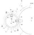
- the support portion 42 of the support mechanism 4a has one support member 8c.
- the support mechanism 4 has the support portion 42 that contacts the inner circumferential surface 5b of the ring-shaped member 5 in one circumferential range (W31) around the reference axis (Oa).
- W31 circumferential range
- Oa reference axis
- the number of parts that make up the support mechanism 4a is kept low.
- the inner diameter side support member 8c that makes up the support mechanism 4a has a shoe.
- the circumferential width of the portion (seat surface (support surface, contact surface) 9c) of one inner diameter side support member 8c that contacts the inner surface 5b of the ring-shaped member 5 is set to ⁇ 2 when expressed as a central angle centered on the central axis Oa of the ring-shaped member 5.
- ⁇ 2 can be 20° or more and 90° or less, 30° or more and 90° or less, 45° or more and 180° or less, or 75° or more and 90° or less.
- ⁇ 2 is approximately 20, 25, 30, 35, 40, 45, 50, 55, 60, 65, 70, 75, 80, 85, 90, 95, 100, 105, 110, 115, 120, 125, 130, 135, 140, 145, 150, 155, 160, 165, 170, 175, or 180°.
- ⁇ 2 is 90°.
- the above values are just examples and are not limited to these.
- the inner diameter side support member 8c has a sector-shaped end face shape with a central angle of ⁇ 2 (90°) when viewed from the axial direction. That is, the tip surface (seat surface) 9c of the inner diameter side support member 8c is formed of a partial cylindrical surface with a central angle of ⁇ 2 (90°), and its radius of curvature is substantially the same as the radius of curvature of the inner circumferential surface 5b of the ring-shaped member 5. That is, the entire tip surface 9c of the inner diameter side support member 8c is in sliding contact with the inner circumferential surface 5b of the ring-shaped member 5.
- the circumferential width (central angle ⁇ 2) of the portion of the inner diameter side support member 8c that contacts the inner circumferential surface 5b of the ring-shaped member 5 is set sufficiently wide, so that the inner circumferential surface 5b of the ring-shaped member 5 can be stably supported.
- the contact width of the inner diameter side support member 8c can be set relatively narrow, as in the support member 8a of the first embodiment.
- the support position (Pf) and the contact position (P10) are essentially in a front-back positional relationship with the wall of the ring-shaped member 5 sandwiched therebetween.
- the support member 8c receives the radially inward force from the grinding wheel 3 acting on the outer circumferential surface 5a of the ring-shaped member 5 on its inner inner circumferential surface 5b.
- the ring-shaped member 5 is supported by the support portion 42 at or near the circumferential position that is essentially the same as the circumferential position where the pressing force of the grinding wheel 3 acts. Changes in the shape of the ring-shaped member 5 are suppressed during the grinding process.
- the front end of the tip surface 9c of the inner diameter side support member 8c in the rotation direction ⁇ of the ring-shaped member 5 is located in the first circumferential range W1.
- the front edge Pf of the tip surface 9c of the inner diameter side support member 8c in the rotation direction ⁇ of the ring-shaped member 5 is positioned at the same circumferential position as the first imaginary straight line L1.
- the edge Pf is positioned forward of the first imaginary straight line L1 in the rotation direction ⁇ of the ring-shaped member 5.
- the edge Pf is positioned at substantially the same circumferential position as the first imaginary straight line L1.
- the rear end of the tip surface 9c of the inner diameter side support member 8c in the rotation direction ⁇ of the ring-shaped member 5 is located in the second circumferential range W2.
- the rear edge Pr of the tip surface 9c of the inner diameter side support member 8c in the rotation direction ⁇ of the ring-shaped member 5 is positioned at substantially the same circumferential position as the second virtual straight line L2.
- the support mechanism 4b has elastic members (biasing members) 26a, 26b that elastically bias the inner diameter side support members 8a, 8b toward the inner circumferential surface 5b of the ring-shaped member 5.
- each of the inner diameter side support members 8a, 8b is supported on a support base (not shown) constituting the support mechanism 4b so as to be capable of displacement in the radial direction of the ring-shaped member 5.
- each of the inner diameter side support members 8a, 8b is elastically biased toward the inner peripheral surface 5b of the ring-shaped member 5 by elastic members 26a, 26b assembled between the inner diameter side support members 8a, 8b and the support base.
- each of the elastic members 26a, 26b is made of a coil spring.
- the elastic members 26a, 26b can be made of various elastic members such as leaf springs and disc springs.
- the shoes (shoe tips) of the inner diameter side support members 8a, 8b can be made of an elastic body such as rubber or resin.
- each elastic member 26a, 26b is adjusted.
- the pressing force of the grinding surface 7 of the grinding wheel 3 against the outer peripheral surface 5a of the ring-shaped member 5 is prevented from becoming excessively large.
- the ring-shaped member 5 is more effectively prevented from elastically deforming into an elliptical shape.
- the contact pressure of the tip surfaces 9a, 9b of the inner diameter side support members 8a, 8b against the inner peripheral surface 5b of the ring-shaped member 5 is prevented from becoming excessively large.
- the occurrence of circumferential scratches (shoe scratches) on the inner peripheral surface 5b is effectively prevented.
- the two inner diameter side support members 8d, 8e in the support mechanism 4c each have a support roller that rolls and contacts the inner circumferential surface 5b of the ring-shaped member 5.
- each of the inner diameter side support members 8d, 8e has a cylindrical outer peripheral surface 27a, 27b, and is supported so as to be freely rotatable about its own central axis by a support base (not shown) that constitutes the support mechanism 4c, with its central axis aligned parallel to the central axis Oa of the ring-shaped member 5.
- the portion of the outer circumferential surface 27a of one of the inner diameter side support members 8d that contacts the inner circumferential surface 5b of the ring-shaped member 5 is present in the first circumferential range W1.
- the circumferential center position P1 of the portion of the outer circumferential surface 27a of one of the inner diameter side support members 8d that contacts the inner circumferential surface 5b of the ring-shaped member 5 is located at the same circumferential position as the first virtual straight line L1.
- the portion of the outer circumferential surface 27b of the other inner diameter side support member 8e that contacts the inner circumferential surface 5b of the ring-shaped member 5 is present in the second circumferential range W2.
- the circumferential center position P2 of the portion of the outer circumferential surface 27b of the other inner diameter side support member 8e that contacts the inner circumferential surface 5b of the ring-shaped member 5 is located at the same circumferential position as the second virtual straight line L2.
- the outer peripheral surfaces 27a, 27b of the inner diameter side support members 8d, 8e are in rolling contact with the inner peripheral surface 5b of the ring-shaped member 5, so that it is possible to prevent the inner peripheral surface 5b from being scratched in the circumferential direction.
- the rotary drive mechanism 2a has a drive roller 28 having an outer peripheral surface 29 that frictionally engages with the inner peripheral surface 5b of the ring-shaped member 5, instead of a backing plate.
- the drive roller 28 has a cylindrical outer peripheral surface 29.
- the central axis of the drive roller 28 is arranged parallel to the central axis Oa of the ring-shaped member 5.
- the drive roller 28 is driven to rotate around its own central axis.
- the drive roller 28 when grinding the outer peripheral surface 5a of the ring-shaped member 5, the drive roller 28 is positioned on the radially inner side of the ring-shaped member 5 in a circumferential position that does not interfere with the two inner diameter side support members 8a, 8b.
- the outer peripheral surface 29 of the drive roller 28 is frictionally engaged with the inner peripheral surface 5b of the ring-shaped member 5. In this state, the drive roller 28 is driven to rotate, thereby rotating the ring-shaped member 5.
- the driving roller 28 frictionally engaged with the inner peripheral surface 5b of the ring-shaped member 5 is rotated, thereby rotating the ring-shaped member 5. Therefore, even if the radial thickness of the ring-shaped member 5 is small and it is difficult to magnetically attract the axial end surface of the ring-shaped member 5 to the backing plate, the ring-shaped member 5 rotates stably.
- the ring-shaped member 5 rotates stably.
- the support mechanism 4d further includes an outer diameter side support member 30 that contacts the outer peripheral surface 5a of the ring-shaped member 5 to support the ring-shaped member 5 in the radial direction.
- the support mechanism 4d includes a support portion 42 that contacts the inner peripheral surface 5b of the ring-shaped member 5 in at least one circumferential range (W11) around the reference axis (Oa) and contacts the outer peripheral surface 5a of the ring-shaped member 5 in at least another circumferential range (W71).
- the support mechanism 4d has one outer diameter side support member 30. In another example, the support mechanism 4d can have multiple outer diameter side support members.
- the support mechanism 4d in comparison with the example of FIG. 1, has an inner diameter side support member 8a, and also has an outer diameter side support member 30 instead of the inner diameter side support member 8b.
- the outer diameter side support member 30 has a shoe. In another example, the outer diameter side support member 30 can have a support roller as shown in the example of FIG. 9.
- the support member 30 has a seat (tip surface, support surface, contact surface) 31 that contacts the outer peripheral surface 5a of the ring-shaped member 5 and supports the ring-shaped member 5. At least a portion of the seat 31 has a curved shape that corresponds to the curved shape of the outer peripheral surface 5a of the ring-shaped member 5.
- the support portion 42 (support member 8a, support member 30) does not substantially move in the circumferential direction, and the circumferential positions of the support members 8a and 30 are constant.
- the inner peripheral surface 5b or the outer peripheral surface 5a of the ring-shaped member 5 moves in the circumferential direction relative to the support portion 42 (seat surface 9a of the support member 8a, seat surface 31 of the support member 30).
- the seat 9a slides against the inner peripheral surface 5b of the ring-shaped member 5, and the seat 31 slides against the outer peripheral surface 5a.
- the outer diameter side support member 30 is supported and fixed to a support base (not shown) that constitutes the support mechanism 4d.
- the outer diameter side support member 30 has a tip surface (seat surface, support surface, contact surface) 31 that slides against the outer peripheral surface 5a of the ring-shaped member 5.
- the tip surface 31 is formed of a partially cylindrical surface that is curved along the outer peripheral surface 5a of the ring-shaped member 5.
- the radius of curvature of the tip surface 31 is substantially the same as the radius of curvature of the outer peripheral surface 5a of the ring-shaped member 5.
- the tip surface 31 is in surface contact with the outer peripheral surface 5a of the ring-shaped member 5.
- the tip portion (seat surface) of the outer diameter side support member 30, which is a shoe can be in line contact or point contact with the outer peripheral surface 5a of the ring-shaped member 5.
- the circumferential center position P1 of the portion of the inner diameter side support member 8a that contacts the inner peripheral surface 5b of the ring-shaped member 5 and the circumferential center position Q of the portion of the outer diameter side support member 30 that contacts the outer peripheral surface 5a of the ring-shaped member 5 can be positioned apart from each other by ⁇ 3 when expressed as a central angle centered on the central axis Oa of the ring-shaped member 5.
- the angle between one imaginary straight line La connecting the circumferential center position P1 and the central axis Oa of the ring-shaped member 5 and the other imaginary straight line Lc connecting the circumferential center position Q and the central axis Oa of the ring-shaped member 5 can be ⁇ 3.
- ⁇ 3 can be, for example, 20° to 160°, 75° to 105°, or 90° to 105°.
- ⁇ 3 is about 10, 15, 20, 25, 30, 35, 40, 45, 50, 55, 60, 65, 70, 75, 80, 85, 90, 95, 100, 105, 110, 115, 120, 125, 130, 135, 140, 145, 150, 155, 160, 165, 170, 175, or 180°.
- ⁇ 3 is 90°.
- the above values are merely examples and are not limiting.
- the circumferential position and shape of the outer diameter side support member 30 are regulated so that at least a part of the tip surface 31, which is the part of the outer diameter side support member 30 that contacts the outer peripheral surface 5a of the ring-shaped member 5, is in a third circumferential range W3 in which the central angle around the central axis Oa of the ring-shaped member 5 is in the range of ⁇ 3, based on a third virtual line L3 that extends from the central axis Oa of the ring-shaped member 5 in a direction shifted by 90° in the rotation direction ⁇ of the ring-shaped member 5 with respect to the first virtual line L1, when viewed from the axial direction of the ring-shaped member 5.
- ⁇ 3 can be 45° or 22.5°.
- ⁇ 3 can be approximately 60, 55, 50, 45, 40, 35, 30, 25, 20, 15, 10, or 5°. The above values are examples and are not limited to these.
- the third virtual straight line L3 can be a straight line extending from the central axis of the ring-shaped member 5 in a direction shifted by 90° from the first virtual straight line L1 in the opposite direction to the rotation direction of the ring-shaped member 5.
- the circumferential position of the outer diameter side support member 30 and the shape of the tip surface 31 are regulated so that the entire portion of the tip surface 31 of the outer diameter side support member 30 that contacts the outer peripheral surface 5a of the ring-shaped member 5 is within the third circumferential range W3.
- the angle between the third imaginary straight line L3 and the other imaginary straight line Lc can be -45° to +45°, 0° to +45°, or 0° to +15°, assuming that the direction of rotation ⁇ of the ring-shaped member 5 is positive.
- the angle between the third imaginary straight line L3 and the other imaginary straight line Lc is set to 0°, and the circumferential center position Q of the tip surface 31 of the outer diameter side support member 30 is positioned on the third imaginary straight line L3.
- the processing device can be provided with a mechanism for moving the outer diameter side support member 30 closer to the outer diameter of the ring-shaped member in response to the reduction in the outer diameter of the outer diameter surface 5a as processing of the outer diameter surface 5a of the ring-shaped member 5 progresses.
- a configuration can be adopted in which the support mechanism 4d has an elastic member (biasing member) that elastically biases the outer diameter side support member 30 toward the outer diameter surface 5a of the ring-shaped member 5.
- the processing device for ring-shaped members includes a rotation drive mechanism for rotating a metal ring-shaped member in a predetermined direction, a grindstone that is pressed against the outer peripheral surface of the ring-shaped member to process the outer peripheral surface of the ring-shaped member, and a support mechanism having an inner diameter side support member that contacts the inner peripheral surface of the ring-shaped member and supports the ring-shaped member in the radial direction.
- the support mechanism has a plurality of the inner diameter side support members.
- the support mechanism has two of the inner diameter side support members.
- the circumferential center positions of the portions of the two inner diameter side support members that are adjacent in the circumferential direction of the ring-shaped member that contact the inner peripheral surface of the ring-shaped member are positioned at a distance of 20° to 160° from each other when expressed as a central angle centered on the central axis of the ring-shaped member.
- the inner diameter side support member is composed of a shoe that slides against the inner peripheral surface of the ring-shaped member.
- the circumferential width of the portion of the inner diameter side support member that contacts the inner peripheral surface of the ring-shaped member is 45° or more and 180° or less when expressed as a central angle centered on the central axis of the ring-shaped member.
- the support mechanism has an elastic member that elastically biases the inner diameter side support member toward the inner peripheral surface of the ring-shaped member.
- the inner diameter side support member is composed of a support roller that rolls and contacts the inner peripheral surface of the ring-shaped member.
- the rotation drive mechanism has a backing plate that rotates the ring-shaped member while magnetically adsorbing the axial end face of the ring-shaped member.
- the rotation drive mechanism includes a drive roller having an outer circumferential surface that frictionally engages with the inner or outer circumferential surface of the ring-shaped member.
- the grindstone is a rotating grindstone that rotates around its own central axis and presses its outer circumferential surface against the outer circumferential surface of the ring-shaped member.
- At least a portion of the portion of the inner diameter side support member that contacts the inner peripheral surface of the ring-shaped member is present in a first circumferential range in which the central angle around the central axis of the ring-shaped member is within a range of ⁇ 45° when viewed from the axial direction of the ring-shaped member, based on a first imaginary line connecting the central axis of the ring-shaped member and the central axis of the grinding wheel.
- At least a portion of the portion of the inner diameter side support member that contacts the inner peripheral surface of the ring-shaped member is present in a second circumferential range in which the central angle around the central axis of the ring-shaped member is within a range of ⁇ 45°, based on a second imaginary line that extends from the central axis of the ring-shaped member in a direction that forms an angle of 90° with the first imaginary line, when viewed from the axial direction of the ring-shaped member.
- the grindstone is composed of a rotating grindstone that rotates around its own central axis in the direction opposite to the predetermined direction and such that the peripheral speed of the grindstone is faster than the peripheral speed of the ring-shaped member, while pressing its outer peripheral surface against the outer peripheral surface of the ring-shaped member, and the second virtual line extends from the central axis of the ring-shaped member in a direction shifted by 90° from the first virtual line in the opposite direction to the rotation direction of the ring-shaped member.
- At least a portion of one of the multiple support members that contacts the inner circumferential surface of the ring-shaped member is configured to be in the first circumferential range, and at least a portion of another of the multiple support members that contacts the inner circumferential surface of the ring-shaped member is configured to be in the second circumferential range.
- a portion of the support member that contacts the inner circumferential surface of the ring-shaped member is configured to be in the first circumferential range, and another portion of the support member that contacts the inner circumferential surface of the ring-shaped member is configured to be in the second circumferential range.
- the support mechanism further includes an outer diameter side support member that contacts the outer peripheral surface of the ring-shaped member and supports the ring-shaped member in the radial direction.
- the support mechanism has only the inner diameter side support member out of the inner diameter side support member and the outer diameter side support member that contacts the outer peripheral surface of the ring-shaped member and supports the ring-shaped member in the radial direction.
- the method for processing a ring-shaped member uses the above-mentioned ring-shaped member processing device to process the outer circumferential surface of the ring-shaped member by pressing the grindstone against the outer circumferential surface of the ring-shaped member while supporting a metallic ring-shaped member in the radial direction with the support mechanism and driving the ring-shaped member to rotate in the predetermined direction around the central axis of the ring-shaped member with the rotation drive mechanism.
- a method for manufacturing a bearing including a ring-shaped member includes a step of processing the outer circumferential surface of the ring-shaped member by the above-mentioned method for processing the ring-shaped member.
- the bearing includes an inner ring as the ring-shaped member.
- the bearing includes an outer ring as the ring-shaped member.
- the method for manufacturing a mechanical device is a method for manufacturing a mechanical device including a bearing, and includes a step of manufacturing the bearing by the above-mentioned method for manufacturing a bearing.
- the method for manufacturing a vehicle is a method for manufacturing a vehicle including a bearing, and includes a step of manufacturing the bearing by the above-mentioned method for manufacturing a bearing.
Landscapes
- Engineering & Computer Science (AREA)
- General Engineering & Computer Science (AREA)
- Mechanical Engineering (AREA)
- Manufacturing & Machinery (AREA)
- Grinding Of Cylindrical And Plane Surfaces (AREA)
- Rolling Contact Bearings (AREA)
- Constituent Portions Of Griding Lathes, Driving, Sensing And Control (AREA)
Abstract
Description
本願は、2023年11月16日に出願された特願2023-195436号に基づき優先権を主張し、その内容をここに援用する。
第1実施形態について、図1~図6を用いて説明する。
第2実施形態について、図7を用いて説明する。
第3実施形態について、図8を用いて説明する。
第4実施形態について、図9を用いて説明する。
第5実施形態について、図10を用いて説明する。
第6実施形態について、図11を用いて説明する。
第7実施形態について、図12を用いて説明する。
2、2a 回転駆動機構
3 砥石
4、4a、4b、4c、4d 支持機構
5 リング状部材
5a 外周面
5b 内周面
6 バッキングプレート
7 研削面
8a、8b、8c、8d、8e 内径側支持部材
9a、9b、9c 先端面
10 電動モータ
11 ハウジング
12 出力軸
13a、13b 軸受
14 モータステータ
15 モータロータ
16 ハウジング本体
17 蓋体
18 底部
19 保持凹部
20 内輪
21 外輪
22 玉
23 保持器
24 内輪軌道
25 外輪軌道
26a、26b 弾性部材
27a、27b 外周面
28 駆動ローラ
29 外周面
30 外径側支持部材
31 先端面
40 研削機構
100 研削装置
101 バッキングプレート
102 砥石
103 リング状部材
104 シュー
105 研削面
Claims (22)
- 基準軸周りの周方向に金属製のリング状部材を回転させる回転駆動機構と、
前記リング状部材の外周面に押し付けられる砥石を有する研削機構と、
前記基準軸周りの少なくとも1つの周範囲において前記リング状部材の内周面に接触される支持部を有し、前記リング状部材を支持する支持機構と、を備える、リング状部材の加工装置。 - 前記少なくとも1つの周範囲は、前記砥石と前記リング状部材との接触位置に対応する周位置を含む、請求項1に記載のリング状部材の加工装置。
- 前記支持部は、各々が前記リング状部材の前記内周面に接触される複数の内径側支持部材を有する、請求項1又は2に記載のリング状部材の加工装置。
- 前記複数の内径側支持部材は、第1支持範囲を有する第1部材と、第2支持範囲を有する第2部材とを有し、前記第1支持範囲の周方向中心位置と前記第2支持範囲の周方向中心位置との間の角度は、20゜以上160゜以下である、請求項3に記載のリング状部材の加工装置。
- 前記支持部は、前記リング状部材の前記内周面に摺接するシューを有する、請求項1から4のうちのいずれかに記載のリング状部材の加工装置。
- 前記支持部は、前記リング状部材の前記内周面に接触可能な領域を有し、前記領域に対応する中心角が20゜以上180゜以下である、請求項5に記載のリング状部材の加工装置。
- 前記支持機構は、前記支持部を前記リング状部材の前記内周面に向けて付勢する付勢部材を有する、請求項5又は6に記載のリング状部材の加工装置。
- 前記支持部は、前記リング状部材の前記内周面に転がり接触する、請求項1から7のうちのいずれかに記載のリング状部材の加工装置。
- 前記回転駆動機構は、前記リング状部材を磁気吸着により保持する保持部材を有し、前記リング状部材を回転駆動する、請求項1から8のうちのいずれかに記載のリング状部材の加工装置。
- 前記回転駆動機構は、前記リング状部材の前記内周面または前記外周面に摩擦係合される外周面を有する駆動ローラを備える、請求項1から9のうちのいずれかに記載のリング状部材の加工装置。
- 前記砥石は、回転しながら前記リング状部材の前記外周面に押し付けられる、請求項1から10のうちのいずれかに記載のリング状部材の加工装置。
- 前記支持部のうちで前記リング状部材の内周面に接触する部分の少なくとも一部が、前記リング状部材の軸方向から見た場合に、前記リング状部材の中心軸と前記砥石の中心軸とを結ぶ第1仮想直線を基準として、前記リング状部材の中心軸を中心とする中心角が±45゜の範囲である第1周方向範囲に存在する、請求項1から11のうちのいずれかに記載のリング状部材の加工装置。
- 前記支持部のうちで前記リング状部材の内周面に接触する部分の少なくとも一部が、前記リング状部材の軸方向から見た場合に、前記リング状部材の中心軸から前記第1仮想直線となす角度が90゜となる方向に伸長する第2仮想直線を基準として、前記リング状部材の中心軸を中心とする中心角が±45゜の範囲である第2周方向範囲に存在する、請求項12に記載のリング状部材の加工装置。
- 前記砥石は、自身の中心軸を中心に前記所定方向と反対方向に、かつ、自身の外周面の周速が前記リング状部材の外周面の周速よりも速くなるように回転しながら、自身の外周面を前記リング状部材の外周面に押し付けられる回転砥石により構成され、
前記第2仮想直線が、前記リング状部材の中心軸から、前記第1仮想直線に対して前記リング状部材の回転方向と反対方向に90゜ずれた方向に伸長する、請求項13に記載のリング状部材の加工装置。 - 前記支持機構は、前記リング状部材の外周面に接触して該リング状部材を径方向に支持する外径側支持部材をさらに有する、請求項1から14のうちのいずれかに記載のリング状部材の加工装置。
- 前記支持機構は、前記内径側支持部材と、前記リング状部材の外周面に接触して該リング状部材を径方向に支持する外径側支持部材とのうち、前記内径側支持部材のみを有する、請求項1から15のうちのいずれかに記載のリング状部材の加工装置。
- 基準軸周りの周方向に金属製のリング状部材を回転させる工程と、
前記リング状部材の外周面に砥石を押し付ける工程であり、前記基準軸周りの少なくとも1つの周範囲において前記リング状部材の内周面に支持部を接触させて前記リング状部材を支持する工程を含む、前記工程と、
を備える、リング状部材の加工方法。 - リング状部材を含む軸受の製造方法であって、請求項17に記載のリング状部材の加工方法を用いて前記リング状部材の外周面を加工する工程を備える、軸受の製造方法。
- 前記軸受は、前記リング状部材として内輪を備える、請求項18に記載の軸受の製造方法。
- 前記軸受は、前記リング状部材として外輪を備える、請求項18に記載の軸受の製造方法。
- 請求項18に記載の製造方法を用いて機械部品を製造する工程と、
前記機械部品を装置本体に取り付ける工程と、
を備える、機械装置の製造方法。 - 請求項18に記載の製造方法を用いて軸受を製造する工程と、
前記軸受を車両本体に取り付ける工程と、
を備える、車両の製造方法。
Priority Applications (5)
| Application Number | Priority Date | Filing Date | Title |
|---|---|---|---|
| EP24861315.0A EP4578598A4 (en) | 2023-11-16 | 2024-09-03 | DEVICE AND METHOD FOR PROCESSING RING-SHAPED ELEMENTS, METHOD FOR MANUFACTURED BEARINGS, METHOD FOR MANUFACTURED MACHINE PARTS, AND METHOD FOR MANUFACTURED VEHICLES |
| CN202480067394.4A CN122121982A (zh) | 2023-11-16 | 2024-09-03 | 环状部件的加工装置及加工方法、轴承的制造方法、机械装置的制造方法以及车辆的制造方法 |
| JP2025501775A JP7831681B2 (ja) | 2023-11-16 | 2024-09-03 | リング状部材の研削装置および研削方法、軸受の製造方法、機械装置の軸の取付方法、ならびに、車両の軸の取付方法 |
| JP2026034035A JP2026083272A (ja) | 2023-11-16 | 2026-03-04 | リング状部材の加工装置および加工方法、軸受の製造方法、機械装置の製造方法、ならびに、車両の製造方法 |
| US19/638,301 US20260235163A1 (en) | 2023-11-16 | 2026-04-03 | Processing device and processing method for ring-shaped member, method for manufacturing bearing, method for manufacturing mechanical device, and method for manufacturing vehicle |
Applications Claiming Priority (2)
| Application Number | Priority Date | Filing Date | Title |
|---|---|---|---|
| JP2023195436 | 2023-11-16 | ||
| JP2023-195436 | 2023-11-16 |
Related Child Applications (1)
| Application Number | Title | Priority Date | Filing Date |
|---|---|---|---|
| US19/638,301 Continuation US20260235163A1 (en) | 2023-11-16 | 2026-04-03 | Processing device and processing method for ring-shaped member, method for manufacturing bearing, method for manufacturing mechanical device, and method for manufacturing vehicle |
Publications (1)
| Publication Number | Publication Date |
|---|---|
| WO2025105019A1 true WO2025105019A1 (ja) | 2025-05-22 |
Family
ID=95154792
Family Applications (1)
| Application Number | Title | Priority Date | Filing Date |
|---|---|---|---|
| PCT/JP2024/031579 Pending WO2025105019A1 (ja) | 2023-11-16 | 2024-09-03 | リング状部材の加工装置および加工方法、軸受の製造方法、機械装置の製造方法、ならびに、車両の製造方法 |
Country Status (5)
| Country | Link |
|---|---|
| US (1) | US20260235163A1 (ja) |
| EP (1) | EP4578598A4 (ja) |
| JP (2) | JP7831681B2 (ja) |
| CN (1) | CN122121982A (ja) |
| WO (1) | WO2025105019A1 (ja) |
Citations (6)
| Publication number | Priority date | Publication date | Assignee | Title |
|---|---|---|---|---|
| JPH07299711A (ja) * | 1994-05-09 | 1995-11-14 | Nippon Seiko Kk | 断面円形薄肉部材の研削方法 |
| JP2004195651A (ja) | 2004-04-05 | 2004-07-15 | Nsk Ltd | 断面円形薄肉部材の研削方法及び薄肉玉軸受内輪の研削方法 |
| JP2008307619A (ja) * | 2007-06-12 | 2008-12-25 | Toyo Advanced Technologies Co Ltd | 研削装置 |
| JP6337475B2 (ja) * | 2014-01-21 | 2018-06-06 | 株式会社ジェイテクト | 心なしシュー研削のシミュレーション装置 |
| JP2019042864A (ja) | 2017-09-01 | 2019-03-22 | 日本精工株式会社 | リング状部材の研削装置および研削方法、並びに、ラジアル軸受の製造方法 |
| JP6488894B2 (ja) * | 2015-06-05 | 2019-03-27 | 株式会社ジェイテクト | 円筒ワークの研削加工装置 |
Family Cites Families (9)
| Publication number | Priority date | Publication date | Assignee | Title |
|---|---|---|---|---|
| DE968296C (de) * | 1952-04-04 | 1958-01-30 | Landis Tool Co | Schleifmaschine zum Schleifen der Aussenflaechen ringfoermiger Werkstuecke |
| GB793638A (en) * | 1954-08-02 | 1958-04-23 | Landis Tool Co | Improvements in or relating to the grinding of ring-like workpieces |
| IT1083520B (it) * | 1977-06-15 | 1985-05-21 | Famir Int Spa | Rettificatrice per pezzi anulari da lavorare esternamente o internamente |
| JP2003071702A (ja) * | 2001-09-05 | 2003-03-12 | Nsk Ltd | 玉軸受軌道面の超仕上加工方法および超仕上研削構造体 |
| RU2228250C2 (ru) * | 2002-07-22 | 2004-05-10 | Общество с ограниченной ответственностью "ТЕХНОМАШ" | Шлифовальный станок |
| CN107685258A (zh) * | 2016-06-28 | 2018-02-13 | 无锡市思博瑞机电有限公司 | 一种轴承内框外框打磨机构 |
| US10207332B2 (en) * | 2016-07-29 | 2019-02-19 | Jtekt Corporation | Work holder and work machining method |
| CN112873003A (zh) * | 2019-11-14 | 2021-06-01 | 卡如(江苏)临床营养品有限公司 | 一种用于波齿复合垫加工的垫片抛光装置 |
| CN116619205B (zh) * | 2023-06-15 | 2026-02-27 | 八环科技集团股份有限公司 | 一种轴承内圈加工设备及加工工艺 |
-
2024
- 2024-09-03 JP JP2025501775A patent/JP7831681B2/ja active Active
- 2024-09-03 CN CN202480067394.4A patent/CN122121982A/zh active Pending
- 2024-09-03 WO PCT/JP2024/031579 patent/WO2025105019A1/ja active Pending
- 2024-09-03 EP EP24861315.0A patent/EP4578598A4/en active Pending
-
2026
- 2026-03-04 JP JP2026034035A patent/JP2026083272A/ja active Pending
- 2026-04-03 US US19/638,301 patent/US20260235163A1/en active Pending
Patent Citations (6)
| Publication number | Priority date | Publication date | Assignee | Title |
|---|---|---|---|---|
| JPH07299711A (ja) * | 1994-05-09 | 1995-11-14 | Nippon Seiko Kk | 断面円形薄肉部材の研削方法 |
| JP2004195651A (ja) | 2004-04-05 | 2004-07-15 | Nsk Ltd | 断面円形薄肉部材の研削方法及び薄肉玉軸受内輪の研削方法 |
| JP2008307619A (ja) * | 2007-06-12 | 2008-12-25 | Toyo Advanced Technologies Co Ltd | 研削装置 |
| JP6337475B2 (ja) * | 2014-01-21 | 2018-06-06 | 株式会社ジェイテクト | 心なしシュー研削のシミュレーション装置 |
| JP6488894B2 (ja) * | 2015-06-05 | 2019-03-27 | 株式会社ジェイテクト | 円筒ワークの研削加工装置 |
| JP2019042864A (ja) | 2017-09-01 | 2019-03-22 | 日本精工株式会社 | リング状部材の研削装置および研削方法、並びに、ラジアル軸受の製造方法 |
Non-Patent Citations (1)
| Title |
|---|
| See also references of EP4578598A4 |
Also Published As
| Publication number | Publication date |
|---|---|
| JP2026083272A (ja) | 2026-05-19 |
| JPWO2025105019A1 (ja) | 2025-05-22 |
| US20260235163A1 (en) | 2026-08-13 |
| JP7831681B2 (ja) | 2026-03-17 |
| EP4578598A4 (en) | 2026-01-21 |
| EP4578598A1 (en) | 2025-07-02 |
| CN122121982A (zh) | 2026-05-29 |
Similar Documents
| Publication | Publication Date | Title |
|---|---|---|
| CN104608046B (zh) | 轴承圆柱滚子圆柱面的超精加工方法 | |
| EP3674034B1 (en) | Workpiece support device, machining device, machining method, bearing manufacturing method, vehicle manufacturing method, and mechanical device manufacturing method | |
| JP6911547B2 (ja) | 溝の超仕上げ方法及び軸受の製造方法 | |
| JP2008023596A (ja) | 微細凹部加工方法 | |
| JP7035383B2 (ja) | リング状部材の研削装置および研削方法、並びに、ラジアル軸受の製造方法 | |
| JP2010240807A (ja) | ころ端面加工用ワーク供給装置、ころ端面加工機、および転がり軸受用ころ | |
| JP2009024708A (ja) | 転がり軸受用軌道輪の製造方法 | |
| JP7831681B2 (ja) | リング状部材の研削装置および研削方法、軸受の製造方法、機械装置の軸の取付方法、ならびに、車両の軸の取付方法 | |
| JP2024073241A (ja) | 逃げ部加工装置、逃げ部加工方法、および軸受用外輪製造方法 | |
| JP2012187648A (ja) | ワーク内面の研削方法 | |
| WO2006027986A1 (ja) | 動圧軸受装置用軸部材およびその製造方法 | |
| JP2003117784A (ja) | ワーク研削装置およびワーク研削方法 | |
| JP2001140902A (ja) | 玉軸受軌道面の超仕上加工方法 | |
| JP2001304267A (ja) | 摺動部材およびその製造方法 | |
| WO2006104130A1 (ja) | 超仕上砥石及びそれを用いた超仕上加工方法 | |
| JP4581843B2 (ja) | 転がり軸受用軌道輪の製造方法 | |
| JP2008095943A (ja) | 車輪軸受装置の製造方法 | |
| JP2002192450A (ja) | トロイダル型無段変速機用転動体の加工方法および加工装置 | |
| JP2002303329A (ja) | 転がり軸受とその製造方法並びにロール支持構造 | |
| JP2003071702A (ja) | 玉軸受軌道面の超仕上加工方法および超仕上研削構造体 | |
| JP3870950B2 (ja) | 断面円形薄肉部材の研削方法及び薄肉玉軸受内輪の研削方法 | |
| JP3539090B2 (ja) | 研削装置 | |
| JP4788132B2 (ja) | 砥石車装置及びこれを備えた研削盤 | |
| JP2001347446A (ja) | テープ研磨装置 | |
| WO2024025816A1 (en) | Low-friction sanding assemblies and machines |
Legal Events
| Date | Code | Title | Description |
|---|---|---|---|
| ENP | Entry into the national phase |
Ref document number: 2025501775 Country of ref document: JP Kind code of ref document: A |
|
| WWE | Wipo information: entry into national phase |
Ref document number: 2025501775 Country of ref document: JP |
|
| ENP | Entry into the national phase |
Ref document number: 2024861315 Country of ref document: EP Effective date: 20250311 |
|
| 121 | Ep: the epo has been informed by wipo that ep was designated in this application |
Ref document number: 24861315 Country of ref document: EP Kind code of ref document: A1 |
|
| WWP | Wipo information: published in national office |
Ref document number: 2024861315 Country of ref document: EP |
|
| NENP | Non-entry into the national phase |
Ref country code: DE |