AU2014404792B2 - Washing machine sprayer apparatus and drum washing machine having same - Google Patents
Washing machine sprayer apparatus and drum washing machine having same Download PDFInfo
- Publication number
- AU2014404792B2 AU2014404792B2 AU2014404792A AU2014404792A AU2014404792B2 AU 2014404792 B2 AU2014404792 B2 AU 2014404792B2 AU 2014404792 A AU2014404792 A AU 2014404792A AU 2014404792 A AU2014404792 A AU 2014404792A AU 2014404792 B2 AU2014404792 B2 AU 2014404792B2
- Authority
- AU
- Australia
- Prior art keywords
- water
- water circulating
- guide surface
- water guide
- sprinkling device
- Prior art date
- Legal status (The legal status is an assumption and is not a legal conclusion. Google has not performed a legal analysis and makes no representation as to the accuracy of the status listed.)
- Active
Links
Classifications
-
- D—TEXTILES; PAPER
- D06—TREATMENT OF TEXTILES OR THE LIKE; LAUNDERING; FLEXIBLE MATERIALS NOT OTHERWISE PROVIDED FOR
- D06F—LAUNDERING, DRYING, IRONING, PRESSING OR FOLDING TEXTILE ARTICLES
- D06F39/00—Details of washing machines not specific to a single type of machines covered by groups D06F9/00 - D06F27/00
- D06F39/08—Liquid supply or discharge arrangements
- D06F39/088—Liquid supply arrangements
-
- A—HUMAN NECESSITIES
- A47—FURNITURE; DOMESTIC ARTICLES OR APPLIANCES; COFFEE MILLS; SPICE MILLS; SUCTION CLEANERS IN GENERAL
- A47L—DOMESTIC WASHING OR CLEANING; SUCTION CLEANERS IN GENERAL
- A47L15/00—Washing or rinsing machines for crockery or tableware
- A47L15/42—Details
- A47L15/4278—Nozzles
Landscapes
- Engineering & Computer Science (AREA)
- Textile Engineering (AREA)
- Detail Structures Of Washing Machines And Dryers (AREA)
Abstract
A washing machine sprayer apparatus (1) and a drum washing machine having same. The washing machine sprayer apparatus (1) comprises: a water flow element (10), where a water flow channel is provided within the water flow element (10), a water inlet (11) in communication with the water flow channel is provided on the upper end surface of the water flow element, and a water outlet (12) in communication with the water flow channel is provided on the lower end surface; a water guide element (20), where the water guide element (20) is provided below the water flow element (10), the water guide element (20) is provided with a conical water guide surface (21) opposite the water outlet (12); and, multiple diversion elements (30), where the lower extremities of the multiple diversion elements (30) are equidistantly connected onto the conical water guide surface (21) in the circumferential direction of the conical water guide surface (21) and arranged between the apex and the outer circumferential edge of the conical water guide surface (21), and the upper extremities of the multiple diversion elements (30) respectively are connected to the water flow element (10).
Description
Date of Filing: 2014.11.10 (33) Country
CN
CN (71) Applicant(s)
Wuxi Little Swan Co., Ltd.
(72) Inventor(s)
Zuo, Meng;Hu, Wei (74) Agent / Attorney
Spruson & Ferguson, GPO Box 3898, Sydney, NSW, 2001, AU (56) Related Art
WO 2012141407 A CN 2372345 Y CN 203782434 U (12) ϋΚϋΦί* (19) ffl Rr M (43)51^^0
2016^34 3 0 (03.03.2016)
WIPOIPCT (10)
WO 2016/029553 Al (51)
D06F 39/08 (2006.01) (21) PCT/CN2014/090748 (22) Β^Φ-WB: 2014411)! 10 B (10.11.2014) (25) Φ-WMW: 44 (26) 44 (30)
201410433180.2 2014 4 8 4 28 B (28.08.2014) CN 201420493110.1 2014 4 8 4 28 B (28.08.2014) CN (71) 4WA: (WUXI LITTLE
SWAN CO., LTD.) [CN/CN]; Ψ 3444 44)(3
4434B# 18 4, Jiangsu 214028 (CN) = (72) £l$A: £$£ (ZUO, Meng); Ψ34444£§44 £O)tI344SB# 18 4, Jiangsu 214028 (CN) = i$fli (hu, Wei); 4 34444£§44O)t34444- is 4, Jiangsu 214028 (CN) = (74) ftSA: Offl
4 ) (TSINGYIHUA INTELLECTUAL PROPERTY LLC); 43!b44S43iW43liW4444 W4W441 301 7, Beijing 100084 (CN).
(81) #b£B (^44444 444-44®«W34«
4): AE, AG, AL, AM, AO, AT, AU, AZ, BA, BB, BG, BH, BN, BR, BW, BY, BZ, CA, CH, CL, CN, CO, CR, CU, CZ, DE, DK, DM, DO, DZ, EC, EE, EG, ES, FI, GB, GD, GE, GH, GM, GT, HN, HR, HU, ID, IL, IN, IR, IS, JP, KE, KG, KN, KP, KR, KZ, LA, LC, LK, LR, LS, LU, LY, MA, MD, ME, MG, MK, MN, MW, MX, MY, MZ, NA, NG, NI, NO, NZ, OM, PA, PE, PG, PH, PL, PT, QA, RO, RS, RU, RW, SA, SC, SD, SE, SG, SK, SL, SM, ST, SV, SY, TH, TJ, TM, TN, TR, TT, TZ, UA, UG, US, UZ, VC, VN, ZA, ZM, ZW = (84) #b£B (^44444
4): ARIPO (BW, GH, GM, KE, LR, LS, MW, MZ, NA, RW, SD, SL, ST, SZ, TZ, UG, ZM, ZW), 1)4 (AM, AZ, BY, KG, KZ, RU, TJ, TM), OH (AL, AT, BE, BG, CH, CY, CZ, DE, DK, EE, ES, FI, FR, GB, GR, HR, HU, IE, [JO44] (54) Title: WASHING MACHINE SPRAYER APPARATUS AND DRUM WASHING MACHINE HAVING SAME (54) : /44MSW#^fi4444SW4(44M

WO 2016/029553 Al
AA Up BB Down (57) Abstract: A washing machine sprayer apparatus (1) and a drum washing machine having same. The washing machine sprayer apparatus (1) comprises: a water flow element (10), where a water flow channel is provided within the water flow element (10), a water inlet (11) in communication with the water flow channel is provided on the upper end surface of the water flow element, and a water outlet (12) in communication with the water flow channel is provided on the lower end surface; a water guide element (20), where the water guide element (20) is provided below the water flow element (10), the water guide element (20) is provided with a conical water guide surface (21) opposite the water outlet (12); and, multiple diversion elements (30), where the lower extremities of the multiple diversion elements (30) are equidistantly connected onto the conical water guide surface (21) in the circumferential direction of the conical water guide surface (21) and arranged between the apex and the outer circumferential edge of the conical water guide surface (21), and the upper extremities of the multiple diversion elements (30) respectively are connected to the water flow element (10).
(57)jft<: —(ί) 4444SW444M, d) 444 ϋτΚ4 do) , 44ί1τΚ4 do) 444ffl7Kilit, 4r4il7K#&!±7roW4444riiil7Kil ΐϊι4ί1&ϋ®τΚπ di) 447fflW4444riiil7Kilitj4il&!47K □ (12) ; 4tK4 (20) , 4γ44τΚ4 (20) 4444ί1τΚ4 do) 344, 444τΚ4 (20) 4444τ44τΚπ (12) (21) ; 44444 do) , 4444444 do) (21) 144344Bi44®44 eW/KW (21) ±4444W44tKW (21) 444444 4414, 4444444 do) 3±^4^444ί1τΚ4 do) 44=
WO 2016/029553 Al llllllllllllllllllllllllllllllllllllllllllllllllll^
IS, IT, LT, LU, LV, MC, MK, MT, NL, NO, PL, PT, RO, RS, SE, SI, SK, SM, TR), OAPI (BF, BJ, CF, CG, CI, CM, GA, GN, GQ, GW, KM, ML, MR, NE, SN, TD, TG) =
- WOT+^^(OJ^ 21 ^(3))o
2014404792 28 Sep 2018
SPRINKLING DEVICE FOR WASHING MACHINE AND FRONT-LOADING WASHING
MACHINE HAVING SAME
TECHNICAL FIELD
The present disclosure relates to a technical field of manufacturing washing machines, and more particularly, to a sprinkling device for a washing machine and a front-loading washing machine having the same.
BACKGROUND
For a washing machine in the related art, some foam will stick to a door seal and a door body after a detergent dissolves during a laundry process, which not only reduces a utilization rate of the detergent, but also leads to foam residue after rinsing. Subsequent water inflow will wash the residual foam into clothes, resulting in secondary addition of the detergent, such that the washing is not clean, and the washing time and washing effect are affected. Some washing machines are additionally equipped with a sprinkling device, but a sprinkling effect is limited.
SUMMARY
The present disclosure aims to solve at least one of the above technical problems in the prior art to at least some extent. Accordingly, one objective of the present disclosure is to provide a sprinkling device for a washing machine, which may provide advantages in terms of enhancing a utilization rate of a detergent, decreasing washing time or improving a washing effect.
Another objective of the present disclosure is to provide a front-loading washing machine having the sprinkling device.
In order to achieve the above objectives, embodiments of a first aspect of the present disclosure provide a sprinkling device for a washing machine. The sprinkling device includes: a water circulating member, internally provided with a water circulating passage, in which an upper end face of the water circulating member is provided with a water inlet in communication with the water circulating passage, and a lower end face of the water circulating member is provided with a water outlet in communication with the water circulating passage; a water guide member, disposed below the water circulating member, and having a tapered water guide surface opposite
PIDM143561PAU
2014404792 28 Sep 2018 the water outlet; and a plurality of shunting members, in which lower ends of the plurality of shunting members are connected to the tapered water guide surface equidistantly along a circumferential direction of the tapered water guide surface and located between an apex and an outer circumference of the tapered water guide surface; upper ends of the plurality of shunting members are connected with the water circulating member respectively.
For the sprinkling device according to embodiments of the present disclosure, by providing the water guide member having the tapered water guide surface, and the plurality of shunting members, it is possible to sprinkle uniformly in the form of a 360-degree sheet shape. Compared with the sprinkling device in the related art, the sprinkling device according to embodiments of the present disclosure has a better sprinkling effect. Therefore, a door body and a door seal of the washing machine and clothes therein may be washed simultaneously, such that a detergent is fully dissolved, foam residue is reduced, and a washing effect is improved while decreasing the washing time of the clothes.
Moreover, the sprinkling device according to embodiments of the present disclosure may further have the following additional technical features.
According to an embodiment of the present disclosure, the tapered water guide surface is configured as a conical surface, and a cross section of the shunting member extends along a radial direction of the tapered water guide surface.
According to an embodiment of the present disclosure, three shunting devices are provided.
According to an embodiment of the present disclosure, the water circulating passage is configured as a cylindrical passage, and the water inlet is communicated with an upper end of the water circulating passage while the water outlet is communicated with a lower end of the water circulating passage. Thus, the water in the water circulating passage of the water circulating member may flow more smoothly.
According to an embodiment of the present disclosure, a central axis of the water circulating passage coincides with a central axis of the tapered water guide surface. Thus, it may be ensured that a water flow out of the water outlet is accurately impinged at the apex of the tapered water guide surface.
According to an embodiment of the present disclosure, the water circulating passage has a diameter of 6 to 9 mm, and a distance between the apex of the tapered water guide surface and
PIDM143561PAU
2014404792 28 Sep 2018 the lower end face of the water circulating member is 3 to 5 mm.
According to an embodiment of the present disclosure, a taper angle of the tapered water guide surface ranges from 120° to 130°, and a distance between the lower end of the shunting member and the outer circumference of the tapered water guide surface is 1.5 to 2.5 mm.
According to an embodiment of the present disclosure, a lower end of the water circulating member is provided with a connecting ring extending along a circumferential direction of an outer circumferential surface of the water circulating member, and the upper end of the shunting member is connected to the connecting ring, so as to facilitate connection between the shunting members and the water circulating member without affecting the shunting effect.
According to an embodiment of the present disclosure, the water circulating member, the connecting ring, the water guide member and the plurality of shunting members are formed integrally, which can not only enhance an overall structural strength of the sprinkling device, but also simplify a production process of the sprinkling device to decrease a production cost of the sprinkling device.
A front-loading washing machine is provided according to embodiments of a second aspect of the present disclosure. The front-loading washing machine includes: a cabinet, provided with a clothes access port; an inner tub, disposed in the cabinet; a door seal, disposed to the cabinet and surrounding the clothes access port; a door body, disposed to the cabinet to open or close the clothes access port; and at least one sprinkling device, configured as a sprinkling device for a washing machine according to embodiments of the first aspect of the present disclosure, and disposed to the door seal and located in the cabinet.
By being provided with the sprinkling device according to embodiments of the first aspect of the present disclosure, the front-loading washing machine according to embodiments of the present disclosure has advantages of a high detergent utilization rate, short washing time and a better washing effect.
According to an embodiment of the present disclosure, three sprinkling devices are arranged evenly in a circumferential direction of the door seal. Therefore, the water flow out of the three sprinkling devices may be sprinkled uniformly in the 360 degrees.
BRIEF DESCRIPTION OF THE DRAWINGS
PIDM143561PAU
2014404792 28 Sep 2018
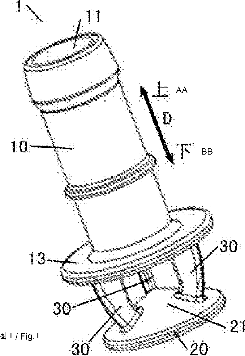
Fig. 1 is a perspective view of a sprinkling device for a washing machine according to an embodiment of the present disclosure;
Fig. 2 is a schematic view of dimensions of a sprinkling device for a washing machine according to an embodiment of the present disclosure;
Fig. 3 is a partial schematic view of a water flow structure of a sprinkling device for a washing machine according to an embodiment of the present disclosure.
Reference numerals: sprinkling device 1 for washing machine, water circulating member 10, water inlet 11, water outlet 12, connecting ring 13, water guide member 20, tapered water guide surface 21, shunting member 30.
DETAILED DESCRIPTION
Reference will now be made in detail to exemplary embodiments, examples of which are illustrated in the accompanying drawings. The same or similar elements and the elements having same or similar functions are denoted by like reference numerals throughout the descriptions. The embodiments described herein with reference to the drawings are explanatory, which aim to illustrate the present disclosure, but shall not be construed to limit the present disclosure.
A sprinkling device 1 for a washing machine according to embodiments of the present disclosure will be described below with reference to drawings.
As shown in Figs. 1 to 3, the sprinkling device 1 according to embodiments of the present disclosure includes a water circulating member 10, a water guide member 20 and a plurality of shunting members 30.
The water circulating member 10 internally has a water circulating passage; an upper end face of the water circulating member 10 is provided with a water inlet 11 in communication with the water circulating passage, and a lower end face of the water circulating member is provided with the water inlet 11 in communication with the water circulating passage (an up-and-down direction as indicated by arrow A in Fig. 1).
The water guide member 20 is disposed below the water circulating member 10; an upper surface of the water guide member 20 is configured as a tapered water guide surface 21 opposite to the water outlet 12; and the tapered water guide surface 21 is a tapered surface projecting in a direction towards the water outlet 12.
PIDM143561PAU
2014404792 28 Sep 2018
Lower ends of the plurality of shunting members 30 are connected to the tapered water guide surface 21 equidistantly along a circumferential direction of the tapered water guide surface 21, and upper ends of the plurality of shunting members 30 are connected with the water circulating member 10 respectively, so as to connect the water circulating member 10 with the water guide member 20. The lower ends of the plurality of shunting members 30 are located between an apex and an outer circumference of the tapered water guide surface 21. In other words, in a radial direction of the tapered water guide surface 21, the lower ends of the plurality of shunting members 30 have a predetermined distance from the apex and the outer circumference of the tapered water guide surface 21 respectively.
A sprinkling process of the sprinkling device 1 according to embodiments of the present disclosure will be described below. As shown in Fig. 3 (broken lines in Fig. 3 indicating a flow direction of a water flow), the water flow enters the water circulating passage of the water circulating member 10 through the water inlet 11 of the water circulating member 10, and flows out of the water outlet 12 along the water circulating passage. The water flow out of the water outlet 12 is impinged at the apex of the tapered water guide surface 2; the water flow presents a sheet shape after passing by the apex of the tapered water guide surface 21, and then is scattered out in a number of directions by encountering with the plurality of shunting members 30; the water flow scattered in a number of directions converges again when passing by the outer circumference of the tapered water guide surface 21; finally forming the water flow sprinkled uniformly in a 360-degree sheet shape.
For the sprinkling device 1 according to embodiments of the present disclosure, by providing the water guide member 20 having the tapered water guide surface 21, and the plurality of shunting members 30, it is possible to sprinkle uniformly in the form of the 360-degree sheet shape. Compared with the sprinkling device in the related art, the sprinkling device 1 according to embodiments of the present disclosure has a better sprinkling effect. Therefore, a door body and a door seal of the washing machine and clothes therein may be washed simultaneously, such that a detergent is fully dissolved, foam residue is reduced, and a washing effect is improved while decreasing the washing time of the clothes. Thus, the sprinkling device 1 according to embodiments of the present disclosure has advantages of enhancing a utilization rate of the detergent, reducing the washing time and improving the washing effect.
PIDM143561PAU
2014404792 28 Sep 2018
The sprinkling device 1 according to specific embodiments of the present disclosure will be described below with reference to the drawings.
In some specific embodiments of the present disclosure, as shown in Figs. 1 to 3, the sprinkling device 1 according to embodiments of the present disclosure includes the water circulating member 10, the water guide member 20 and three shunting members 30.
A lower surface of the water guide member 20 is circular, and the tapered water guide surface 21 is a conical surface. A cross section of the shunting member 30 extends along the radial direction of the tapered water guide surface 21, and connection lines, between two adjacent shunting members 30 and the apex of the tapered water guide surface 21, form an included angle of 120 degrees. Hence, it is possible to improve a guiding effect of the tapered water guide surface 21 on the water flow, and a shunting effect of the shunting member 30 on the water flow, thereby further enhancing uniformity of water sprinkling.
Further, the water circulating member 10 is configured as a substantially cylindrical shape; the water circulating passage is configured as a cylindrical passage; the water inlet 11 is communicated with an upper end of the water circulating passage while the water outlet 12 is communicated with a lower end of the water circulating passage; a central axis of the water circulating passage coincides with a central axis of the tapered water guide surface 21. Therefore, the water flow may be more smooth within the water circulating passage of the water circulating member 10, and it may be ensured that the water flow out of the water outlet 12 is accurately impinged at the apex of the tapered water guide surface 21, thus further improving the sprinkling effect of the sprinkling device 1.
In some specific embodiments of the present disclosure, as shown in Fig. 2, the water circulating passage has a diameter of 6 to 9 mm; a distance A between the apex of the tapered water guide surface 21 and the lower end face of the water circulating member 10 is 3 to 5 mm; a taper angle B of the tapered water guide surface 21 ranges from 120° to 130°; a distance C between the lower end of the shunting member 30 and the outer circumference of the tapered water guide surface 21 is 1.5 to 2.5 mm. Therefore, it is possible to ensure the sprinkling effect of the sprinkling device 1, and reduce a volume of the sprinkling device 1 to facilitate installation of the sprinkling device 1 within the washing machine.
In some specific embodiments of the present disclosure, as shown in Figs. 1 and 2, a lower
PIDM143561PAU
2014404792 28 Sep 2018 end of the water circulating member 10 is provided with a connecting ring 13 extending along a circumferential direction of an outer circumferential surface of the water circulating member 10, and the upper ends of the plurality of shunting members 30 are connected to a lower surface of the connecting ring 13 equidistantly along a circumferential direction of the connecting ring 13, so as to facilitate connection between the shunting members 30 and the water circulating member 10 without affecting the shunting effect.
Advantageously, the water circulating member 10, the connecting ring 13, the water guide member 20 and the plurality of shunting members 30 are formed integrally, which can not only enhance an overall structural strength of the sprinkling device 1, but also simplify a production process of the sprinkling device 1 to decrease a production cost of the sprinkling device 1.
A front-loading washing machine according to embodiments of the present disclosure will be described below.
The front-loading washing machine according to embodiments of the present disclosure includes a cabinet (not shown), an inner tub (not shown), a door seal (not shown), a door body (not shown) and at least one sprinkling device.
The cabinet is provided with a clothes access port. The inner tub is disposed in the cabinet. The door seal is disposed to the cabinet and surrounds the clothes access port. The door body is disposed to the cabinet to open or close the clothes access port. The sprinkling device is configured as the sprinkling device 1 according to the above embodiments, and the sprinkling device 1 is disposed to the door seal and located within the cabinet.
By being provided with the sprinkling device 1 according to the above embodiments of the present disclosure, the front-loading washing machine according to embodiments of the present disclosure has advantages of a high detergent utilization rate, short washing time and a better washing effect.
Alternatively, three sprinkling devices 1 are arranged evenly in a circumferential direction of the door seal. Therefore, the water flow out of the three sprinkling devices 1 may be sprinkled uniformly in the 360 degrees.
Other configurations and operations of the front-loading washing machine according to embodiments of the present disclosure are known to those skilled in the art, which will not be described in detail herein.
PIDM143561PAU
2014404792 28 Sep 2018
It could be appreciated by those skilled in the art that the number of the sprinkling device 1 in the front-loading washing machine may be set to more than one depending on actual applications and requirements, and the sprinkling device 1 may also be applied to other types of washing machines, for example, a pulsator-type washing machine.
In the specification, it is to be understood that terms such as “central,” “longitudinal,” “transverse,” “length,” “width,” “thickness,” “upper,” “lower,” “front,” “rear,” “left,” “right,” “vertical,” “horizontal,” “top,” “bottom,” “inner,” “outer,” “clockwise,” and “counterclockwise” should be construed to refer to the orientation as then described or as shown in the drawings under discussion. These relative terms are for convenience of description and do not require that the device or element be constructed or operated in a particular orientation, shall not be construed to limit the present disclosure.
In addition, terms such as “first” and “second” are used herein for purposes of description and are not intended to indicate or imply relative importance or significance or to imply the number of indicated technical features. Thus, the feature defined with “first” and “second” may comprise one or more of this feature. In the description of the present disclosure, “a plurality of’ means two or more than two, unless specified otherwise.
In the present disclosure, unless specified or limited otherwise, the terms “mounted,” “connected,” “coupled,” “fixed” and the like are used broadly, and may be, for example, fixed connections, detachable connections, or integral connections; may also be mechanical or electrical connections; may also be direct connections or indirect connections via intervening structures; may also be inner communications of two elements, which can be understood by those skilled in the art according to specific situations.
In the present disclosure, unless specified or limited otherwise, a structure in which a first feature is “on” or “below” a second feature may include an embodiment in which the first feature is in direct contact with the second feature, and may also include an embodiment in which the first feature and the second feature are not in direct contact with each other, but are contacted via an additional feature formed therebetween. Furthermore, a first feature “on,” “above,” or “on top of’ a second feature may include an embodiment in which the first feature is right or obliquely “on,” “above,” or “on top of’ the second feature, or just means that the first feature is at a height higher than that of the second feature; while a first feature “below,” “under,” or “on bottom of’ a
PIDM143561PAU
2014404792 28 Sep 2018 second feature may include an embodiment in which the first feature is right or obliquely “below,” “under,” or “on bottom of’ the second feature, or just means that the first feature is at a height lower than that of the second feature.
Reference throughout this specification to “an embodiment,” “some embodiments,” “an example,” or “a specific example,” means that a particular feature, structure, material, or characteristic described in connection with the embodiment or example is included in at least one embodiment or example of the present disclosure. Thus, the appearances of the phrases in various places throughout this specification are not necessarily referring to the same embodiment or example of the present disclosure. Furthermore, the particular features, structures, materials, or characteristics may be combined in any suitable manner in one or more embodiments or examples. Furthermore, different embodiments or examples in thus specification can be jointed and combined by those skilled in the art without mutual contradiction.
The term “comprise”, or “comprising” throughout this specification is used in an inclusive sense.
Although explanatory embodiments have been shown and described, it would be appreciated by those skilled in the art that the above embodiments cannot be construed to limit the present disclosure, and changes, alternatives, and modifications can be made in the embodiments without departing from spirit, principles and scope of the present disclosure.
Accordingly, it is to be understood that the scope of the invention is not to be limited to the exact construction and operation described and illustrated, but only by the following claims which are intended to include all suitable modifications and equivalents permitted by the applicable law.
Reference to background art or other prior art in this specification is not an admission that such background art or other prior art is common general knowledge in Australia or elsewhere.
PIDM143561PAU
2014404792 28 Sep 2018
Claims (11)
- What is claimed is:1. A sprinkling device for a washing machine, comprising:a water circulating member, internally provided with a water circulating passage, wherein an upper end face of the water circulating member is provided with a water inlet in communication with the water circulating passage, and a lower end face of the water circulating member is provided with a water outlet in communication with the water circulating passage;a water guide member, disposed below the water circulating member, and having a tapered water guide surface opposite the water outlet; and a plurality of shunting members, wherein lower ends of the plurality of shunting members are connected to the tapered water guide surface equidistantly along a circumferential direction of the tapered water guide surface and located between an apex and an outer circumference of the tapered water guide surface; upper ends of the plurality of shunting members are connected with the water circulating member respectively.
- 2. The sprinkling device according to claim 1, wherein the tapered water guide surface is configured as a conical surface, and a cross section of the shunting member extends along a radial direction of the tapered water guide surface.
- 3. The sprinkling device according to claim 2, wherein three shunting devices are provided.
- 4. The sprinkling device according to claim 2, wherein the water circulating passage is configured as a cylindrical passage, and the water inlet is communicated with an upper end of the water circulating passage while the water outlet is communicated with a lower end of the water circulating passage.
- 5. The sprinkling device according to claim 4, wherein a central axis of the water circulating passage coincides with a central axis of the tapered water guide surface.
- 6. The sprinkling device according to any one of claims 1 to 5, wherein the water circulating passage has a diameter of 6 to 9 mm, and a distance between the apex of the tapered water guide surface and the lower end face of the water circulating member is 3 to 5 mm.
- 7. The sprinkling device according to claim 6, wherein a taper angle of the tapered water guide surface ranges from 120° to 130°, and a distance between the lower end of the shunting member and the outer circumference of the tapered water guide surface is 1.5 to 2.5 mm.ioPIDM143561PAU2014404792 28 Sep 2018
- 8. The sprinkling device according to claim 1, wherein a lower end of the water circulating member is provided with a connecting ring extending along a circumferential direction of an outer circumferential surface of the water circulating member, and the upper end of the shunting member is connected to the connecting ring.
- 9. The sprinkling device according to claim 8, wherein the water circulating member, the connecting ring, the water guide member and the plurality of shunting members are formed integrally.
- 10. A front-loading washing machine, comprising: a cabinet, provided with a clothes access port;an inner tub, disposed in the cabinet;a door seal, disposed to the cabinet and surrounding the clothes access port;a door body, disposed to the cabinet to open or close the clothes access port; and at least one sprinkling device, configured as a sprinkling device for a washing machine according to any one of claims 1 to 9, and disposed to the door seal and located in the cabinet.
- 11. The front-loading washing machine according to claim 10, wherein three sprinkling devices are arranged evenly in a circumferential direction of the door seal.PIDM143561PAUFig. 11/3PIDM143561PAU ftFig.2 ft2/3PIDM143561PAUFig 33/3PIDM143561PAU
Applications Claiming Priority (5)
| Application Number | Priority Date | Filing Date | Title |
|---|---|---|---|
| CN201410433180.2A CN105369566B (en) | 2014-08-28 | 2014-08-28 | The spray equipment of washing machine and the roller washing machine with it |
| CN201410433180.2 | 2014-08-28 | ||
| CN201420493110.1 | 2014-08-28 | ||
| CN201420493110.1U CN204112117U (en) | 2014-08-28 | 2014-08-28 | The spray equipment of washing machine and there is its roller washing machine |
| PCT/CN2014/090748 WO2016029553A1 (en) | 2014-08-28 | 2014-11-10 | Washing machine sprayer apparatus and drum washing machine having same |
Publications (2)
| Publication Number | Publication Date |
|---|---|
| AU2014404792A1 AU2014404792A1 (en) | 2017-04-13 |
| AU2014404792B2 true AU2014404792B2 (en) | 2018-11-01 |
Family
ID=55398702
Family Applications (1)
| Application Number | Title | Priority Date | Filing Date |
|---|---|---|---|
| AU2014404792A Active AU2014404792B2 (en) | 2014-08-28 | 2014-11-10 | Washing machine sprayer apparatus and drum washing machine having same |
Country Status (4)
| Country | Link |
|---|---|
| EP (1) | EP3187649B1 (en) |
| AU (1) | AU2014404792B2 (en) |
| BR (1) | BR112017004126B1 (en) |
| WO (1) | WO2016029553A1 (en) |
Families Citing this family (1)
| Publication number | Priority date | Publication date | Assignee | Title |
|---|---|---|---|---|
| CH716044A1 (en) * | 2019-04-05 | 2020-10-15 | V Zug Ag | Nozzle for cleaning a container. |
Citations (3)
| Publication number | Priority date | Publication date | Assignee | Title |
|---|---|---|---|---|
| CN2372345Y (en) * | 1999-05-12 | 2000-04-05 | 海尔集团公司 | Spray device of drum washing machine |
| WO2012141407A2 (en) * | 2011-04-14 | 2012-10-18 | 엘지전자 주식회사 | Washer 세탁기 |
| CN203782434U (en) * | 2014-03-20 | 2014-08-20 | Tcl家用电器(合肥)有限公司 | Water outlet head and washing machine |
Family Cites Families (4)
| Publication number | Priority date | Publication date | Assignee | Title |
|---|---|---|---|---|
| JPS6423991U (en) * | 1987-07-28 | 1989-02-08 | ||
| KR19990048168A (en) * | 1997-12-08 | 1999-07-05 | 윤종용 | Drum Washing Machine |
| KR101022225B1 (en) * | 2003-11-18 | 2011-03-17 | 삼성전자주식회사 | Drum washing machine |
| DE102007007354B4 (en) * | 2006-02-20 | 2013-10-10 | Lg Electronics Inc. | Clothes dryer and method of control |
-
2014
- 2014-11-10 BR BR112017004126-0A patent/BR112017004126B1/en active IP Right Grant
- 2014-11-10 WO PCT/CN2014/090748 patent/WO2016029553A1/en not_active Ceased
- 2014-11-10 EP EP14900502.7A patent/EP3187649B1/en active Active
- 2014-11-10 AU AU2014404792A patent/AU2014404792B2/en active Active
Patent Citations (3)
| Publication number | Priority date | Publication date | Assignee | Title |
|---|---|---|---|---|
| CN2372345Y (en) * | 1999-05-12 | 2000-04-05 | 海尔集团公司 | Spray device of drum washing machine |
| WO2012141407A2 (en) * | 2011-04-14 | 2012-10-18 | 엘지전자 주식회사 | Washer 세탁기 |
| CN203782434U (en) * | 2014-03-20 | 2014-08-20 | Tcl家用电器(合肥)有限公司 | Water outlet head and washing machine |
Also Published As
| Publication number | Publication date |
|---|---|
| EP3187649A4 (en) | 2018-05-02 |
| WO2016029553A1 (en) | 2016-03-03 |
| EP3187649A1 (en) | 2017-07-05 |
| BR112017004126B1 (en) | 2022-02-08 |
| BR112017004126A2 (en) | 2017-12-05 |
| AU2014404792A1 (en) | 2017-04-13 |
| EP3187649B1 (en) | 2020-04-01 |
Similar Documents
| Publication | Publication Date | Title |
|---|---|---|
| CN201074281Y (en) | A drum washing machine | |
| CN106120253A (en) | Spray header, self-cleaning structure for drum type washing machine and drum type washing machine | |
| CN204112117U (en) | The spray equipment of washing machine and there is its roller washing machine | |
| CN106283232B (en) | A kind of spinning cleaning flower roll and its drag reduction wave attenuating device | |
| CN104894799A (en) | Washing machine with function of spraying water to clean barrel body | |
| CN105369566A (en) | Spraying device of washing machine, and roller washing machine with same | |
| EP3187649A1 (en) | Washing machine sprayer apparatus and drum washing machine having same | |
| CN205253765U (en) | Copper line tinning stack | |
| CN205347810U (en) | Washing machine and drainage structures thereof | |
| CN204765520U (en) | Dish washer spray arm device and dish washer | |
| CN108532227A (en) | A kind of washing machine water box and washing machine | |
| CN104722592A (en) | Extrusion die for metal tube | |
| CN212505401U (en) | A knitted fabric dyeing device | |
| CN204417663U (en) | A kind of spinning spinning head | |
| CN202323455U (en) | Washing machine with a plurality of waterfall spraying holes | |
| CN114197143A (en) | Flaring-shaped spray header and washing machine | |
| CN203498658U (en) | Spray water outlet device of washing machine and washing machine thereof | |
| CN217419055U (en) | Spray nozzle and washing machine | |
| CN201186998Y (en) | washing machine pulsator | |
| CN213295824U (en) | drum washing machine | |
| CN206189093U (en) | Spray set , condenser assembly and all -in -one washer dryer | |
| CN204491110U (en) | A kind of wool textile additive feeding device | |
| CN205518761U (en) | High -efficient belt cleaning device of copper bar | |
| CN208563462U (en) | a shower device | |
| CN204530232U (en) | A kind of washing machine |
Legal Events
| Date | Code | Title | Description |
|---|---|---|---|
| FGA | Letters patent sealed or granted (standard patent) | ||
| PC | Assignment registered |
Owner name: WUXI LITTLE SWAN ELECTRIC CO., LTD. Free format text: FORMER OWNER(S): WUXI LITTLE SWAN CO., LTD. |