BR102012024903A2 - MEASUREMENT TOUCH PROBE, MEASUREMENT SYSTEM, METHOD FOR LASER OPTICAL DETERMINATION OF THE HEIGHT OF A WIRE GUIDE CYLINDER, AND USE OF THE MEASUREMENT SYSTEM - Google Patents
MEASUREMENT TOUCH PROBE, MEASUREMENT SYSTEM, METHOD FOR LASER OPTICAL DETERMINATION OF THE HEIGHT OF A WIRE GUIDE CYLINDER, AND USE OF THE MEASUREMENT SYSTEM Download PDFInfo
- Publication number
- BR102012024903A2 BR102012024903A2 BR102012024903-0A BR102012024903A BR102012024903A2 BR 102012024903 A2 BR102012024903 A2 BR 102012024903A2 BR 102012024903 A BR102012024903 A BR 102012024903A BR 102012024903 A2 BR102012024903 A2 BR 102012024903A2
- Authority
- BR
- Brazil
- Prior art keywords
- touch probe
- laser
- measurement
- touch
- evaluation unit
- Prior art date
Links
- 238000005259 measurement Methods 0.000 title claims abstract description 84
- 238000000034 method Methods 0.000 title claims abstract description 20
- 230000003287 optical effect Effects 0.000 title claims abstract description 10
- 239000000523 sample Substances 0.000 claims abstract description 128
- 238000011156 evaluation Methods 0.000 claims abstract description 52
- 238000006073 displacement reaction Methods 0.000 claims abstract description 29
- 238000005070 sampling Methods 0.000 claims abstract description 8
- 238000004891 communication Methods 0.000 claims description 11
- 238000005516 engineering process Methods 0.000 claims description 11
- 230000000977 initiatory effect Effects 0.000 claims description 4
- 239000006096 absorbing agent Substances 0.000 claims 1
- 230000035939 shock Effects 0.000 claims 1
- 238000005266 casting Methods 0.000 description 3
- 230000005484 gravity Effects 0.000 description 3
- 229910000831 Steel Inorganic materials 0.000 description 2
- 238000005452 bending Methods 0.000 description 2
- 230000001419 dependent effect Effects 0.000 description 2
- SHFGJEQAOUMGJM-UHFFFAOYSA-N dialuminum dipotassium disodium dioxosilane iron(3+) oxocalcium oxomagnesium oxygen(2-) Chemical compound [O--].[O--].[O--].[O--].[O--].[O--].[O--].[O--].[Na+].[Na+].[Al+3].[Al+3].[K+].[K+].[Fe+3].[Fe+3].O=[Mg].O=[Ca].O=[Si]=O SHFGJEQAOUMGJM-UHFFFAOYSA-N 0.000 description 2
- 238000005098 hot rolling Methods 0.000 description 2
- 239000010959 steel Substances 0.000 description 2
- 241001232981 Curtos Species 0.000 description 1
- 101100229963 Drosophila melanogaster grau gene Proteins 0.000 description 1
- 101150029664 PELO gene Proteins 0.000 description 1
- 240000008042 Zea mays Species 0.000 description 1
- 230000002411 adverse Effects 0.000 description 1
- 238000005097 cold rolling Methods 0.000 description 1
- 230000006835 compression Effects 0.000 description 1
- 238000007906 compression Methods 0.000 description 1
- 238000005336 cracking Methods 0.000 description 1
- 238000009434 installation Methods 0.000 description 1
- 238000012423 maintenance Methods 0.000 description 1
- 239000011159 matrix material Substances 0.000 description 1
- 230000007935 neutral effect Effects 0.000 description 1
- 230000008447 perception Effects 0.000 description 1
- 238000012545 processing Methods 0.000 description 1
- 230000002035 prolonged effect Effects 0.000 description 1
- 238000005096 rolling process Methods 0.000 description 1
- 238000002604 ultrasonography Methods 0.000 description 1
- 238000010618 wire wrap Methods 0.000 description 1
Images


Classifications
-
- B—PERFORMING OPERATIONS; TRANSPORTING
- B22—CASTING; POWDER METALLURGY
- B22D—CASTING OF METALS; CASTING OF OTHER SUBSTANCES BY THE SAME PROCESSES OR DEVICES
- B22D11/00—Continuous casting of metals, i.e. casting in indefinite lengths
- B22D11/12—Accessories for subsequent treating or working cast stock in situ
- B22D11/128—Accessories for subsequent treating or working cast stock in situ for removing
- B22D11/1287—Rolls; Lubricating, cooling or heating rolls while in use
-
- G—PHYSICS
- G01—MEASURING; TESTING
- G01B—MEASURING LENGTH, THICKNESS OR SIMILAR LINEAR DIMENSIONS; MEASURING ANGLES; MEASURING AREAS; MEASURING IRREGULARITIES OF SURFACES OR CONTOURS
- G01B21/00—Measuring arrangements or details thereof, where the measuring technique is not covered by the other groups of this subclass, unspecified or not relevant
-
- G—PHYSICS
- G01—MEASURING; TESTING
- G01B—MEASURING LENGTH, THICKNESS OR SIMILAR LINEAR DIMENSIONS; MEASURING ANGLES; MEASURING AREAS; MEASURING IRREGULARITIES OF SURFACES OR CONTOURS
- G01B11/00—Measuring arrangements characterised by the use of optical techniques
-
- G—PHYSICS
- G01—MEASURING; TESTING
- G01C—MEASURING DISTANCES, LEVELS OR BEARINGS; SURVEYING; NAVIGATION; GYROSCOPIC INSTRUMENTS; PHOTOGRAMMETRY OR VIDEOGRAMMETRY
- G01C15/00—Surveying instruments or accessories not provided for in groups G01C1/00 - G01C13/00
- G01C15/002—Active optical surveying means
- G01C15/004—Reference lines, planes or sectors
-
- G—PHYSICS
- G01—MEASURING; TESTING
- G01B—MEASURING LENGTH, THICKNESS OR SIMILAR LINEAR DIMENSIONS; MEASURING ANGLES; MEASURING AREAS; MEASURING IRREGULARITIES OF SURFACES OR CONTOURS
- G01B21/00—Measuring arrangements or details thereof, where the measuring technique is not covered by the other groups of this subclass, unspecified or not relevant
- G01B21/02—Measuring arrangements or details thereof, where the measuring technique is not covered by the other groups of this subclass, unspecified or not relevant for measuring length, width, or thickness
- G01B21/04—Measuring arrangements or details thereof, where the measuring technique is not covered by the other groups of this subclass, unspecified or not relevant for measuring length, width, or thickness by measuring coordinates of points
-
- G—PHYSICS
- G01—MEASURING; TESTING
- G01B—MEASURING LENGTH, THICKNESS OR SIMILAR LINEAR DIMENSIONS; MEASURING ANGLES; MEASURING AREAS; MEASURING IRREGULARITIES OF SURFACES OR CONTOURS
- G01B5/00—Measuring arrangements characterised by the use of mechanical techniques
- G01B5/004—Measuring arrangements characterised by the use of mechanical techniques for measuring coordinates of points
- G01B5/008—Measuring arrangements characterised by the use of mechanical techniques for measuring coordinates of points using coordinate measuring machines
- G01B5/012—Contact-making feeler heads therefor
-
- G—PHYSICS
- G01—MEASURING; TESTING
- G01C—MEASURING DISTANCES, LEVELS OR BEARINGS; SURVEYING; NAVIGATION; GYROSCOPIC INSTRUMENTS; PHOTOGRAMMETRY OR VIDEOGRAMMETRY
- G01C15/00—Surveying instruments or accessories not provided for in groups G01C1/00 - G01C13/00
- G01C15/002—Active optical surveying means
- G01C15/004—Reference lines, planes or sectors
- G01C15/006—Detectors therefor
Landscapes
- Physics & Mathematics (AREA)
- General Physics & Mathematics (AREA)
- Engineering & Computer Science (AREA)
- Radar, Positioning & Navigation (AREA)
- Remote Sensing (AREA)
- Mechanical Engineering (AREA)
- Length Measuring Devices By Optical Means (AREA)
- Length Measuring Devices With Unspecified Measuring Means (AREA)
Abstract
sonda de toque de medição, sistema de medição, método para determinação ótica por laser da altura de um cilindro guia de fio, e uso do sistema de medição. a invenção refere-se a uma sonda de toque de medição (1) para amostragem de uma superfície circunferencial (21) de um rolo cilindríco (20), e a um método de determinação ótica com laser de uma altura real h~ actual~ de um cilindro guia de fio (20) em um guia de fio por meio de um sistema de medição. é o objetivo de invenção descrever uma sonda de toque de medição (1) e um método por meio do qual a altura real do cilindro guia de fio pode ser determinada rapidamente, com meios simples e com um alto grau de precisão. esse objetivo é alcançado por uma sonda de toque de medição, possuindo pelo menos uma sonda de toque (2) comprendendo uma superfície de toque (3); um perfil guia vertical (4) que é rigidamente conectado à sonda de toque (2); uma unidade de recebimento de laser (5) compreendendo um campo detector (6) e uma unidade de avaliação de distância (7) onde a unidade de recebimento de laser (5) é deslocável em uma direção vertical no perfil guia (4), o campo detector (6) é realizado para detecção de um feixe de laser (8), e a unidade de avaliação de distância (7) pode determinar uma primeiro distância vertical va~1~ do feixe de laser (8) com relação à unidade de recebimento de laser (5); e um dispositivo de medição de deslocamento (9) para determinar uma segunda distância vertical va~ 2~ entre a sonda de toque (2) e a unidade de recebimento de laser (5).touch probe, measuring system, method for laser optical determination of the height of a wire guide cylinder, and use of the measuring system. the invention relates to a measuring touch probe (1) for sampling a circumferential surface (21) of a cylindrical roller (20), and to a method of optical determination with a laser of a current actual height a wire guide cylinder (20) on a wire guide by means of a measuring system. it is the aim of the invention to describe a measuring touch probe (1) and a method by which the actual height of the wire guide cylinder can be determined quickly, with simple means and with a high degree of accuracy. this objective is achieved by a measuring touch probe, having at least one touch probe (2) comprising a touch surface (3); a vertical guide profile (4) that is rigidly connected to the touch probe (2); a laser receiving unit (5) comprising a detector field (6) and a distance evaluation unit (7) where the laser receiving unit (5) is movable in a vertical direction in the guide profile (4), the detector field (6) is performed to detect a laser beam (8), and the distance evaluation unit (7) can determine a first vertical distance va ~ 1 ~ of the laser beam (8) with respect to the receiving laser (5); and a displacement measurement device (9) for determining a second vertical distance va ~ 2 ~ between the touch probe (2) and the laser receiving unit (5).
Description
A presente invenção se refere a uma sonda de toque de medição que é adequada para amostrar uma superfície circunferencial de um rolo cilíndrico (por exemplo, um cilindro em um guia de fio de uma máquina de fundir fios, ou um rolo em um leito de rolo de um aparelho de rolamento a frio ou rolamento a quente ou de uma instalação de processamento de tira). A amostragem é compreendida como sendo a percepção de pelo menos um ponto por contato, onde uma superfície de toque da sonda de toque de medição entra em contato com o ponto na superfície circunferencial.The present invention relates to a touch probe which is suitable for sampling a circumferential surface of a cylindrical roller (for example, a cylinder on a wire guide of a wire melter, or a roller on a roller bed cold rolling or hot rolling apparatus or strip processing facility). Sampling is understood as the perception of at least one point per contact, where a touch surface of the measurement touch probe comes into contact with the point on the circumferential surface.
Adicionalmente, a invenção refere-se a um sistema de medição que é adequado para medição ótica por laser da altura de um rolo cilíndrico.In addition, the invention relates to a measuring system that is suitable for optical laser measurement of the height of a cylindrical roller.
Adicionalmente, a invenção se refere a um método de determinação ótica por laser da altura real HActuai de um cilindro guia de fio em um guia de fios por meio de um sistema de medição. A altura de um cilindro guia de fio é importante para a operação sem problemas de uma máquina de fundição de fios, visto que um fio parcialmente solidificado, em particular, pode suportar apenas baixos níveis de carga mecânica. As cargas mecânicas excessivas, por exemplo, devido a um cilindro guia de fios incorretamente ajustado, pode resultar em tensões de dobra inaceitavelmente altas, que podem resultar em rachaduras no fio, ou mesmo em uma quebra do envoltório fino do fio.In addition, the invention relates to a method of laser optical determination of the actual height of a wire guide cylinder on a wire guide by means of a measurement system. The height of a wire guide cylinder is important for the smooth operation of a wire casting machine, as a partially solidified wire, in particular, can only support low levels of mechanical load. Excessive mechanical loads, for example, due to an incorrectly adjusted wire guide cylinder, can result in unacceptably high bending stresses, which can result in cracking of the wire, or even a break in the thin wire wrap.
Finalmente, a invenção refere-se ao uso do sistema de medição, de acordo com uma das reivindicações 8 a 9, para execução do método de acordo com qualquer uma das reivindicações de 10 a 14.Finally, the invention relates to the use of the measurement system, according to one of claims 8 to 9, for carrying out the method according to any of claims 10 to 14.
É prática comum se nivelar os cilindros em um guia de fios de uma máquina de fundição de fios (também chamados de cilindros guia de fio) em um chamado suporte de nivelamento. Tipicamente nesse caso, uma parte do guia de fios, por exemplo, a estrutura interna ou externa de um segmento guia de fios, é presa ao suporte de nivelamento, e a distância real dos cilindros guia de fio com relação a uma régua de aço é determinada por dispositivos de medição, por exemplo, por um micrômetro de fio. A partir da geometria de instalação do guia de fios, é possível se definir as distâncias do ' ponto de configuração entre a régua e os cilindros, de modo que a altura dos cilindros guia de fio posas ser ajustada exatamente, por exemplo, por calços. Devido à dobra da régua de aço, a determinação das alturas dos cilindros guia de fio é imprecisa e, devido ao grande número de medições manuais, é muito demorada. Uma desvantagem adicional consiste do fato de as alturas não serem percebidas e gravadas automaticamente.It is common practice to level the cylinders on a wire guide of a wire casting machine (also called wire guide cylinders) on a so-called leveling bracket. Typically in this case, a part of the wire guide, for example, the internal or external structure of a wire guide segment, is attached to the leveling bracket, and the actual distance of the wire guide cylinders from a steel ruler is determined by measuring devices, for example, by a wire micrometer. From the geometry of the installation of the wire guide, it is possible to define the distances from the 'configuration point between the ruler and the cylinders, so that the height of the wire guide cylinders can be adjusted exactly, for example, by shims. Due to the bending of the steel strip, the determination of the heights of the wire guide cylinders is inaccurate and, due to the large number of manual measurements, it is very time-consuming. An additional disadvantage is that heights are not automatically perceived and recorded.
Apesar de o nivelamento ótico com laser de um objeto por meio de uma sonda de toque de medição ser conhecido a princípio a partir do campo técnico de metrologia, as sondas de toque de medição realizada de forma rígida existentes são, não obstante, inadequadas para determinar com precisão e rapidez a altura real, devido às diferenças de altura relativamente grandes entre diferentes cilindros de um segmento guia de fio curvo.Although the optical laser leveling of an object by means of a touch probe is known at first from the technical field of metrology, the existing rigidly held touch probes are nevertheless unsuitable for determining accurately and quickly the actual height due to the relatively large height differences between different cylinders of a curved wire guide segment.
É um objetivo da invenção se superar as desvantagens da técnica anterior, e se descrever um método de determinação da altura real de um cilindro guia de fio em um guia de fios, por meio do qual a sonda de toque de medição e o método a altura real do cilindro guia de fios pode ser determinada
- - rapidamente, isso é, dentro de um curto período de tempo para medição e avaliação,
- - com meios que são os mais simples possível;
- - sem avaliação elaborada; e
- - com um alto grau de precisão.
- - pelo menos uma sonda de toque compreendendo uma superfí-cie de toque;
- - um perfil de guia vertical que é rigidamente conectado à sonda de toque;
- - uma unidade de recebimento de laser compreendendo um campo detector e uma unidade de avaliação de distância, onde a unidade de recepção de laser é deslocável em uma direção vertical no perfil guia, o campo detector é realizado para detectar de um feixe de laser, e a unidade de avaliação de distancia pode determinar uma primeira distância vertical VA1 do feixe de laser com relação à unidade de recebimento de laser; e
- - um dispositivo de medição de deslocamento para determinar uma segunda distância vertical VA2 entre a sonda de toque e a unidade de recebimento de laser.
- - quickly, that is, within a short period of time for measurement and evaluation,
- - with means that are as simple as possible;
- - without elaborated evaluation; and
- - with a high degree of precision.
- - at least one touch probe comprising a touch surface;
- - a vertical guide profile that is rigidly connected to the touch probe;
- - a laser receiving unit comprising a detector field and a distance evaluation unit, where the laser receiving unit is displaceable in a vertical direction in the guide profile, the detector field is realized to detect from a laser beam, and the distance evaluation unit can determine a first vertical distance VA1 of the laser beam with respect to the laser receiving unit; and
- - a displacement measurement device for determining a second vertical distance VA2 between the touch probe and the laser receiving unit.
Nesse caso, um ponto na superfície circunferencial do rolo cilíndrico pode ser amostrado por pelo menos uma sonda de toque compreendendo uma superfície de toque. A partir de um ponto, ou possivelmente também a pluralidade de pontos, na superfície circunferencial, possivelmente levando em consideração a geometria (por exemplo, com base no diâmetro do cilindro conhecido), é possível se deduzir a altura do cilindro. A sonda de toque propriamente dita é rigidamente conectada a um perfil guia vertical da sonda de toque de medição, onde o perfil guia pode ter, por exemplo, um perfil redondo ou poligonal. A sonda de toque de medição possui uma unidade de recebimento de laser compreendendo um campo detector, onde o campo detector é realizado para perceber a altura de um feixe de laser. A unidade de recebimento de laser nesse caso é deslocável no perfil guia, de modo que as alturas superiores à extensão longitudinal do campo detector possam ser sentidas. O campo detector compreende basicamente uma pluralidade de detectores discretos, que são dispostos, por exemplo, em uma coluna ou em uma matriz compreendendo uma pluralidade de colunas. O campo detector propriamente dito é conectado a uma unidade de avaliação de distância, onde a última pode determinar a primeira distância vertical do feixe de laser com relação à unidade de recebimento de laser. Visto que a distância da unidade de recebimento de laser com relação à sonda de toque pode ser determinada por meio de um dispositivo de medição de deslocamento, a segunda distância vertical do feixe de laser da sonda de toque é, dessa forma, também totalmente determinada. O dispositivo de medição de deslocamento nesse caso pode ser integrado, por exemplo, no perfil guia, ou pode ser disposto fora do perfil guia. Todos os dispositivos de medição de deslocamento de contato (por exemplo, potenciômetro) ou dispositivos de medição de deslocamento que operam sem contato (por exemplo, um dispositivo de medição de deslocamento ótico ou capacitivo, indutor ou magnetos-trictive) pode ser utilizado para a medição de deslocamento.In that case, a point on the circumferential surface of the cylindrical roller can be sampled by at least one touch probe comprising a touch surface. From a point, or possibly also the plurality of points, on the circumferential surface, possibly taking into account the geometry (for example, based on the known diameter of the cylinder), it is possible to deduce the height of the cylinder. The touch probe itself is rigidly connected to a vertical guide profile of the measurement touch probe, where the guide profile can have, for example, a round or polygonal profile. The measurement touch probe has a laser receiving unit comprising a detector field, where the detector field is realized to perceive the height of a laser beam. The laser receiving unit in this case is movable in the guide profile, so that heights greater than the longitudinal extension of the detector field can be felt. The detector field basically comprises a plurality of discrete detectors, which are arranged, for example, in a column or in a matrix comprising a plurality of columns. The detector field itself is connected to a distance evaluation unit, where the latter can determine the first vertical distance of the laser beam from the laser receiving unit. Since the distance of the laser receiving unit with respect to the touch probe can be determined by means of a displacement measurement device, the second vertical distance of the laser beam from the touch probe is thus also fully determined. The displacement measurement device in this case can be integrated, for example, in the guide profile, or it can be arranged outside the guide profile. All contact displacement measurement devices (eg potentiometer) or displacement measurement devices that operate without contact (eg, an optical or capacitive displacement measurement device, inductor or magneto-trictive) can be used for displacement measurement.
A fim de se garantir a precisão da sonda de toque de medição durante um período de uso prolongado, é vantajoso que a sonda de toque seja realizada de modo a ser permutável.In order to ensure the accuracy of the touch probe during a period of prolonged use, it is advantageous that the touch probe is designed to be interchangeable.
A fim de manter a sonda de toque de medição relativamente simples, robusta e leve, é vantajoso que a sonda de toque de medição tenha um módulo de comunicação para conexão por meio de tecnologia de informação com uma unidade de avaliação, onde o módulo de comunicação é conectado ao dispositivo de medição de deslocamento e à unidade de avaliação de distancia. Como resultado disso, os dados da sonda de toque de medição são transmitidos por meio de tecnologia de informação (por exemplo, com fio ou sem fio) para a unidade de avaliação, por exemplo, para um PC, onde a unidade de avaliação determina a altura do cilindro e, se necessário, calcula um desvio de ponto de configuração/real da altura. Por exemplo, o módulo de comunicação é realizado como uma interface Bluetooth ou WLAN.In order to keep the touch probe relatively simple, robust and light, it is advantageous that the touch probe has a communication module for connection via information technology with an evaluation unit, where the communication module it is connected to the displacement measurement device and the distance evaluation unit. As a result, the data from the touch probe is transmitted via information technology (for example, wired or wireless) to the evaluation unit, for example, to a PC, where the evaluation unit determines the height of the cylinder and, if necessary, calculates a setpoint / actual deviation from the height. For example, the communication module is carried out as a Bluetooth or WLAN interface.
Alternativamente, é da mesma forma possível que a sonda de toque de medição tenha uma unidade de avaliação, onde a unidade de avaliação é conectada ao dispositivo de medição de deslocamento e à unidade de avaliação de distância. Nesse caso, a unidade de avaliação é realizada, por exemplo, como um micro controlador, que é integrado à sonda de toque de medição. É possível nesse caso que a sonda de toque de medição também tenha uma unidade indicadora (por exemplo, um monitor), de modo que a altura possa não apenas ser avaliada na sonda de toque de medição, mas também enviada na mesma.Alternatively, it is just as possible that the touch probe has an evaluation unit, where the evaluation unit is connected to the displacement measurement device and the distance evaluation unit. In this case, the evaluation unit is carried out, for example, as a microcontroller, which is integrated with the measurement touch probe. It is possible in this case that the touch probe also has an indicator unit (for example, a monitor), so that the height can not only be evaluated on the touch probe, but also sent therein.
Para fins de iniciação de uma medição, é rápido para um controle operacional ser contado ao módulo de comunicação ou à unidade de ava-liação pelo dispositivo de tecnologia de sinal. A operação simples é possível se o controle operacional for disposto na sonda de toque de medição.For the purpose of initiating a measurement, it is quick for an operational control to be counted on the communication module or the evaluation unit by the signal technology device. Simple operation is possible if the operational control is arranged on the measuring touch probe.
É possível que a sonda de toque de medição seja colocada de forma confiável em um cilindro guia de fio se uma sonda de toque estiver em cada caso disposta em um membro, onde dois membros encerram um ângulo de 45 < α < 135 . Se a geometria da sonda de toque de medição, o diâmetro do cilindro e a distância entre a sonda de toque e a unidade de recebimento de laser forem conhecidos, a altura do cilindro guia de fio pode ser facilmente determinada.It is possible that the measurement touch probe can be reliably placed in a wire guide cylinder if a touch probe is in each case arranged on a member, where two members have an angle of 45 <α <135. If the geometry of the touch probe, the diameter of the cylinder and the distance between the touch probe and the laser receiving unit are known, the height of the wire guide cylinder can be easily determined.
A colocação pode ser alcançada de uma forma particularmente simples se a sonda de toque de medição possuir pelo menos três sondas de toque, onde duas sondas de toque são dispostas em um primeiro plano e uma sonda de toque é disposta em um segundo plano , e o primeiro plano é alinhado em paralelo ao segundo plano. Isso pode ser realizado, por exemplo, pelo fato de dois membros serem dispostos em série em cada caso, de modo que o dispositivo de recebimento de laser seja disposto em paralelo ao primeiro e ao segundo planos, isso é, um plano normal ao eixo geométrico longitudinal do cilindro.Placement can be achieved in a particularly simple way if the measurement touch probe has at least three touch probes, where two touch probes are arranged in the foreground and a touch probe is arranged in the background, and the first plane is aligned in parallel with the second plane. This can be accomplished, for example, by the fact that two members are arranged in series in each case, so that the laser receiving device is arranged in parallel to the first and second planes, that is, a plane normal to the geometric axis cylinder longitudinal.
Um contato de linha ou ponto de contato definido entre a sonda de toque e a superfície circunferencial pode ser garantido se a superfície de toque possuir um contorno curvo, em particular cilíndrico ou esférico.A line contact or defined contact point between the touch probe and the circumferential surface can be guaranteed if the touch surface has a curved contour, in particular cylindrical or spherical.
A fim de se impedir um deslocamento indesejado da unidade de recebimento de laser depois que a sonda de toque de medição foi colocada, é vantajoso que a sonda de toque de medição tenha um dispositivo de tra-vamento (por exemplo, um dispositivo de fixação ou um parafuso de fixação), para fixar a posição da unidade de recebimento de laser com relação ao perfil guia, ou se ter um amortecedor. O amortecedor (por exemplo, um amortecedor pressurizado a gás) é disposto, por exemplo, entre o perfil guia e a unidade de recebimento de laser, de modo que seja possível se impedir um deslocamento indesejado da unidade de recebimento de laser resultando da força da gravidade da unidade de recebimento de laser.
É vantajoso se um sistema de medição possuir:
um laser;
uma sonda de toque de medição;
uma unidade de avaliação, que é conectada à sonda de toque de medição pelo dispositivo de tecnologia de informação; e
uma unidade de saída, para enviar a altura do cilindro.
Como já mencionado acima, a unidade de avaliação, e possi-velmente também a unidade de saída, podem ser estruturalmente separadas ou integradas à sonda de toque de medição.In order to prevent unwanted displacement of the laser receiving unit after the measuring touch probe has been placed, it is advantageous that the measuring touch probe has a locking device (for example, a clamping device or a fixing screw), to fix the position of the laser receiving unit in relation to the guide profile, or to have a damper. The damper (for example, a gas pressurized damper) is arranged, for example, between the guide profile and the laser receiving unit, so that it is possible to prevent unwanted displacement of the laser receiving unit resulting from the force of the gravity of the laser receiving unit.
It is advantageous if a measuring system has:
a laser;
a measurement touch probe;
an evaluation unit, which is connected to the touch probe by the information technology device; and
an output unit, to send the height of the cylinder.
As already mentioned above, the evaluation unit, and possibly also the output unit, can be structurally separated or integrated with the touch probe.
Preferivelmente, o laser é realizado como laser rotativo, onde o laser rotativo abrangem um plano de luz. Uma sonda de toque de medição pode, dessa forma, ser configurada para diferentes posições sem a necessi-dade de se realinhar o laser.Preferably, the laser is performed as a rotating laser, where the rotating laser covers a plane of light. A touch probe can therefore be configured for different positions without the need to realign the laser.
Para se permitir que a posição da sonda de toque de medição seja percebida, é vantajoso que o sistema de medição compreenda um transmissor e que a sonda de toque de medição compreenda um receptor do sistema de medição de posição, onde o receptor é conectado ao módulo de comunicação ou à unidade de avaliação pelo dispositivo de tecnologia de sinal, de modo que a posição da sonda de toque de medição possa ser determinada. O sistema de medição de posição pode ser, por exemplo, um sistema de medição RFID ativo, um sistema UWB, um sistema WLAN, um sistema de medição por infravermelho ou ultrassom, mas também um GPS ou um chamado sistema de medição de "GPS diferencial”. A posição da sonda de toque de medição pode ser utilizada pra a comparação automatizada da altura real HActual do cilindro com uma altura de ponto de configuração possivelmente dependente de posição HsetPoint, de modo que a unidade de avaliação possa determinar automaticamente um desvio Δ entre uma al-tura de ponto de configuração HSetpoint e a altura real HActual·In order to allow the position of the touch probe to be perceived, it is advantageous that the measurement system comprises a transmitter and that the touch probe comprises a receiver of the position measurement system, where the receiver is connected to the module communication unit or the evaluation unit by the signal technology device, so that the position of the measurement touch probe can be determined. The position measurement system can be, for example, an active RFID measurement system, a UWB system, a WLAN system, an infrared or ultrasound measurement system, but also a GPS or a so-called "differential GPS measurement system" ”The position of the touch probe can be used for automated comparison of the actual actual height of the cylinder with a setpoint height possibly dependent on the HsetPoint position, so that the evaluation unit can automatically determine a Δ deviation between a height of the HSetpoint configuration point and the actual height HActual ·
Adicionalmente, a gravação (dependente de posição) das alturas é possibilitada, a posição de ponto de configuração e a altura real do cilindro guia de fio definem um volume de controle de ponto de configuração cúbico ou retangular, onde o cilindro guia de fio deve ser localizado. Em adição ao desvio da altura real da altura de ponto de configuração, portanto, é possível -também, se necessário, se determinar o desvio do volume de controle real do volume de controle de ponto de configuração (por exemplo, a partir da ' distância dos centros espaciais de gravidade do volume de controle). O volume de controle real é obtido a partir da posição real e da altura real, com as tolerâncias de medição sendo levadas em consideração.In addition, recording (position-dependent) of heights is made possible, the setpoint position and the actual height of the yarn guide cylinder define a cubic or rectangular setpoint control volume, where the yarn guide cylinder should be located. In addition to the deviation from the actual height of the setpoint height, it is therefore possible - also, if necessary, to determine the deviation from the actual control volume from the setpoint control volume (for example, from the 'distance the spatial centers of gravity of the control volume). The actual control volume is obtained from the actual position and the actual height, with measurement tolerances being taken into account.
O objetivo de acordo com a invenção é da mesma forma alcançado por um método de determinação ótica com laser de uma altura real de um cilindro guia de fio em um guia de fio por meio de um sistema de medição, compreendendo um laser, uma sonda de toque de medição, de acordo com qualquer uma das reivindicações de 1 a 7, que compreende o dispositivo de recebimento de laser, um campo de detector, uma unidade de avaliação de distância, uma sonda de toque e uma superfície de toque, e uma unidade de avaliação, que é conectada à sonda de toque de medição por meio de tecnologia de informação, compreendendo as seguintes etapas do método:
posicionamento do laser;
comutação no laser;
amostragem do cilindro guia de fio por meio da sonda de toque de medição, onde pelo menos uma superfície de toque da sonda de toque de medição entra em contato com um ponto na superfície circunferencial do cilindro guia de fio e um feixe de laser intersecta o campo de detector;
iniciação de uma medição;
determinação de uma primeira distância vertical VA^ entre o feixe de laser e a unidade de recebimento de laser, por meio da unidade de avaliação de distância, e uma segunda distância vertical VA2 entre a sonda de toque e a unidade de recebimento de laser, por meio do dispositivo de medição de deslocamento;
cálculo da altura real Hactual do cilindro guia de fio, com HActual = VA1 + VA2 na unidade de avaliação.
Preferivelmente, o laser executa um movimento rotativo, onde o laser abrange um plano de luz.
É vantajoso, depois da etapa de "iniciação de uma medição” que
a posição da sonda de toque de medição seja determinada por um receptor de um sistema de medição de posição;
a posição da sonda de toque de medição seja transmitida para a unidade de avaliação;
a unidade de avaliação determine uma diferença Δ entre uma altura de ponto de configuração HsetPoint e a altura real HActual; e
a diferença Δ seja enviada por uma unidade de saída.
Frequentemente, na medição de um cilindro guia de fio, uma altura de ponto de configuração Hsetpoint é designada para uma posição da sonda de toque de medição.
É rápido se derivar a altura do ponto de configuração Hsetpoint a partir dos dados CAD.
É vantajoso que a altura de ponto de configuração Hsetpoint· a altura real e uma diferença Δ sejam gravados em um registro de medição.
Para uma medição altamente precisa, é vantajoso, na etapa de "posicionamento de laser”, que o laser seja rigidamente (porém removivel-mente) conectado a uma estrutura estacionária do guia de fio ou à base. O laser, dessa forma, sofre concomitantemente os mesmos deslocamentos, ou vibrações, que o guia de fio, de modo que os mesmos não afetem negativamente a precisão.
É vantajoso que o sistema de medição de acordo com uma das reivindicações 8 e 9 seja utilizado para execução do método de acordo com qualquer uma das reivindicações de 10 a 14.The objective according to the invention is likewise achieved by a method of laser optical determination of a real height of a wire guide cylinder on a wire guide by means of a measurement system, comprising a laser, a probe of measurement ring according to any one of
laser positioning;
switching on the laser;
sampling of the wire guide cylinder by means of the touch probe, where at least one touch surface of the wire probe contacts a point on the circumferential surface of the wire guide cylinder and a laser beam intersects the field detector;
initiation of a measurement;
determining a first vertical distance VA ^ between the laser beam and the laser receiving unit, using the distance evaluation unit, and a second vertical distance VA2 between the touch probe and the laser receiving unit, using means of the displacement measurement device;
calculation of the actual height of the wire guide cylinder, with HActual = VA1 + VA2 in the evaluation unit.
Preferably, the laser performs a rotational movement, where the laser covers a plane of light.
It is advantageous, after the "start a measurement" step that
the position of the touch probe is determined by a receiver of a position measurement system;
the position of the touch probe is transmitted to the evaluation unit;
the unit of evaluation determines a difference Δ between a height of the HsetPoint setpoint and the actual height, actual; and
the difference Δ is sent by an output unit.
Often, when measuring a wire guide cylinder, an Hsetpoint setpoint height is assigned to a position of the touch probe.
It is quick to derive the height of the Hsetpoint configuration point from the CAD data.
It is advantageous that the height of the Hsetpoint setpoint · the actual height and a difference Δ are recorded in a measurement log.
For a highly accurate measurement, it is advantageous, in the "laser positioning" step, that the laser is rigidly (but removably) connected to a stationary structure of the wire guide or the base. The laser thus suffers concomitantly the same displacements, or vibrations, as the wire guide, so that they do not adversely affect accuracy.
It is advantageous that the measurement system according to one of
Vantagens e características adicionais da presente invenção são fornecidas pela descrição a seguir de modalidades ilustrativas não limitadoras, onde referência é feita às figuras a seguir, que ilustram o seguinte:
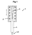
A figura 1 é uma representação em corte de uma primeira modalidade de uma sonda de toque de medição;
A figura 2 é uma representação não em corte da sonda de toque de medição de acordo com a figura 1;
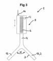
A figura 3 é uma segunda modalidade de uma sonda de toque - de medição possuindo dois membros;
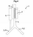
A figura 4 é uma terceira modalidade de uma sonda de toque demedição;
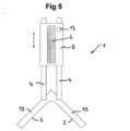
A figura 5 é uma quarta modalidade de uma sonda de toque de medição;
A figura 6 é uma representação da determinação, de acordo com a invenção, da altura de um cilindro guia de fio;
A figura 7 é uma representação da determinação, de acordo com a invenção, da altura para três cilindros guia de fio;
A figura 8 é uma representação da determinação da altura do cilindro guia de fio de acordo com a técnica anterior.Additional advantages and features of the present invention are provided by the following description of illustrative non-limiting modalities, where reference is made to the following figures, which illustrate the following:
Figure 1 is a sectional representation of a first modality of a touch probe;
Figure 2 is a non-sectional representation of the measurement touch probe according to Figure 1;
Figure 3 is a second embodiment of a touch probe - measuring having two members;
Figure 4 is a third embodiment of a touch probe;
Figure 5 is a fourth embodiment of a measurement touch probe;
Figure 6 is a representation of the determination, according to the invention, of the height of a wire guide cylinder;
Figure 7 is a representation of the determination, according to the invention, of the height for three wire guide cylinders;
Figure 8 is a representation of the determination of the height of the wire guide cylinder according to the prior art.
Afigura 1, em uma representação em corte, ilustra uma primeira modalidade da sonda de toque de medição 1. A superfície de circunferencial de um rolo cilíndrico, não representados, pode ser amostrada por meio da sonda de toque de medição 1, onde a superfície de toque esférica 3 da sonda de toque 2 contata a superfície circunferencial. A sonda de toque 2 é conectada a um perfil guia redondo 4, onde a unidade de recebimento de laser 5 pode ser deslocada verticalmente com relação ao perfil guia 4 e é realizada de modo a ser articulável com relação ao eixo geométrico longitudinal do perfil guia 4 (direção de deslocamento representada como uma seta). Para fins de orientação com uma ausência de folga, o perfil guia possui uma superfície aterrada, e a unidade de recebimento de laser 4 possui uma bucha anular. A distância entre a unidade de recebimento de laser 4 e a sonda de toque 2 pode ser determinada por um dispositivo de medição de deslocamento 9, que é realizado como um potenciômetro. Como uma alternativa para o potenciômetro, o dispositivo de medição de deslocamento também pode ser realizado como um dispositivo de medição LVDT, um dispositivo de medição magnetostrictive, ou como uma régua de medição possuindo uma interface elétrica. Disposta entre o perfil guia 4 e o alojamento da unidade de recebimento de laser 5 existe uma mola de compressão que define a posição neutra da sonda de toque de medição e garante um contato definido - entre a superfície de toque 3 e o cilindro.Figure 1, in a sectional representation, illustrates a first modality of the
A figura 2 ilustra o campo de detector 6 do dispositivo de rece-' bimento de laser 5, e um feixe de laser 8, ou um plano de luz 35. A unidade de avaliação de distância 7, que é disposta, como um circuito eletrônico, na extremidade superior do dispositivo de recebimento de laser 5, é conectada ao campo de detector 6, onde a unidade de avaliação de distância 7 pode determinar a primeira distância vertical VA1 do feixe de laser 8 a partir da unidade de recebimento de laser 5. Portanto, visto que a segunda distância vertical VA2 entre a sonda de toque 2 e a unidade de recebimento de laser 5 são conhecidas a partir do dispositivo de medição de deslocamento 9, e a distância vertical VA1 entre a unidade de recebimento de laser 5 e o feixe de laser 8 são conhecidas a partir da unidade de avaliação de distância 7, uma unidade de avaliação na sonda de toque de medição 1 pode determinar a altura real H = VA1 + VA2 do cilindro guia de fio, isso é, a distância entre o feixe de laser 8, 35 e a superfície de toque (especificamente, a borda superior do cilindro guia de fio). A fim de se tornar a operação da sonda de toque de medição 1 mais ergonômica, um controle de operação 12 é disposto na sonda de toque de medição. Depois de o controle de operação 12 ter sido pressionado, as distâncias verticais VA1 e VA2 são determinadas e a altura real Hactual é calculada na unidade de avaliação. A altura real Hactual é então transmitida para uma unidade indicadora - estruturalmente separada da sonda de toque de medição 1 - por meio de um módulo de comunicação, que é realizado como uma interface Bluetooth.Figure 2 illustrates the
A figura 3 ilustra uma segunda modalidade da sonda de toque de medição 1, que possui duas sondas de toque 2, realizadas como membros 13. Os dois membros 13 encerram um ângulo, α = 90 , de modo que duas superfícies de toque 3 dos membros 13 entrem em contato com a superfície circunferencial de um rolo cilíndrico simultaneamente. A partir da geometria dos membros 13, e com o conhecimento do diâmetro do cilindro guia de fio, portanto, é novamente possível se determinar a altura do cilindro guia de fio. Adicionalmente, a sonda de toque de medição 1 possui um receptor 14 de um chamado "GPS diferencial”, de modo que a posição da - sonda de toque de medição em um corredor possa ser determinada durante a amostragem dos cilindros guia de fio. As alturas de ponto de configuração Hsetpoint correspondendo a diferentes posições da sonda de toque de medição podem, dessa forma, ser armazenadas, de modo que a unidade de avaliação possa determinar o desvio Δ = HsetPoint - Hactual em cada caso. No caso dessa modalidade, o dispositivo de medição de deslocamento é integrado ao dispositivo de recebimento de laser 5, como na figura 1.Figure 3 illustrates a second modality of the
A figura 4 ilustra uma terceira modalidade de uma sonda de toque de medição 1, onde, no entanto, diferentemente da figura 3, o dispositivo de medição de deslocamento 9 é disposto fora do dispositivo de recebimento de laser 5. Nesse caso, o dispositivo de medição de deslocamento é realizado como um chamado sistema de medição de deslocamento magne-tostrictive que opera sem contato (ver Balluff "Micropulse”).Figure 4 illustrates a third embodiment of a measuring
A figura 5 ilustra a quarta modalidade de uma sonda de toque de medição 1. Diferentemente da figura 4, a sonda de toque de medição possui dois perfis guia paralelos 4, de modo que a unidade de recebimento de laser 5 seja fixada contra rotação com relação aos membros 13.Figure 5 illustrates the fourth modality of a measuring
A figura 6 ilustra um sistema de medição que é utilizado para determinação da altura de um cilindro guia de fio 20. Em primeiro lugar, um laser rotativo 31 é posicionado em um suporte perto do cilindro guia de fio 20, de modo que o laser, quando ligado, produz um plano de luz horizontal 35 como resultado de um movimento rotativo 34. O cilindro guia de fio 20 é então amostrado por meio da sonda de toque de medição 1, de modo que as superfícies de toque 3 das duas sondas de toque 2 realizadas como membros 13 entrem em contato com a superfície circunferencial 21 do cilindro guia de fio 20. A unidade de recebimento de laser 5 é então deslocada em uma direção vertical no perfil guia circular 4 de tal forma que o feixe de laser 8 do plano de luz 35 forme uma interseção com o campo detector 6. Depois do deslocamento, a posição vertical do dispositivo de recebimento de laser é travada por um dispositivo de fixação ou travamento que age entre o dispositivo de recebimento de laser e o perfil guia, de modo que a força de gravidade não resulte na redução do dispositivo de recebimento de laser 5. Uma -medição é então iniciada, visto que um controle de operação 12 no dispositivo de medição 1 é pressionado. Depois da iniciação da medição, uma uni-’ dade de avaliação de distância na sonda de toque de medição 1 determina uma primeira distância vertical VA1 entre o feixe de laser 8 e a borda inferior da unidade de recebimento de laser 5. Um dispositivo de medição de deslocamento determina a segunda distância vertical VA2 entre a sonda de toque 2 e a borda inferior da unidade de recebimento de laser 5. A altura real do cilindro guia de fio 20 é, portanto, determinada, no entanto, por Hactual = VA1 + VA2, onde a altura real é calculada em uma unidade de avaliação localizada especialmente dentro do dispositivo de recebimento de laser 5, e é exibida pela unidade de saída 32.Figure 6 illustrates a measurement system that is used to determine the height of a
No ajuste do laser, o procedimento pode ser, por exemplo, como se segue: Em primeiro lugar, o laser é fixo. Então, a posição dos quatro tipicamente pontos de suporte de referência do segmento - os pontos onde o segmento é suportado no fio - é determinado pelo dispositivo de medição, onde inicialmente todos os quatro pontos são medidos. A partir dos quatro pontos, um plano de medição de referência é determinado, onde um ponto (por exemplo, o chamado quarto ponto, visto que, como é sabido, três pontos abrangem um plano) é adaptado para o plano de medição de referência, se necessário, por "calçamento”. Se necessário, na medição real das alturas, um segundo receptor de laser é utilizado, o que garante o alinhamento -não necessariamente horizontal - do plano de laser.For laser adjustment, the procedure can be, for example, as follows: First, the laser is fixed. Then, the position of the four typically reference points of reference of the segment - the points where the segment is supported on the wire - is determined by the measuring device, where initially all four points are measured. From the four points, a reference measurement plane is determined, where a point (for example, the so-called fourth point, since, as is known, three points comprise a plane) is adapted to the reference measurement plane, if necessary, by "paving." If necessary, in the actual measurement of heights, a second laser receiver is used, which guarantees the alignment - not necessarily horizontal - of the laser plane.
A figura 7 ilustra a determinação das alturas reais para três cilindros guia de fio 20, onde os cilindros são localizados em níveis diferentes. Pode-se observar nesse caso que a unidade de recebimento de laser 5 deve ser deslocamento verticalmente no perfil guia 4 em cada caso a fim de que o feixe de laser 8, 35 para formar uma interseção com o campo detector 6. Com relação à representação intermediária, a unidade de recebimento de laser 5 na representação da esquerda foi deslocada para baixo, e deslocada para cima na representação da direita. No caso das representações na direita e na esquerda, uma posição não deslocada da unidade de recebimento de laser 5 com relação à representação central, é indicada por uma linha -interrompida. Uma vantagem da capacidade de deslocamento contínuo do dispositivo de recebimento de laser 5 é que uma grande faixa de altura verti-' cal pode ser coberta por meio de uma sonda de toque de medição. Adicionalmente, não existe necessidade de se adaptar uma sonda de toque de medição rígida a diferentes alturas por meio de placas adaptadoras conectáveis ou de enroscar ou hastes adaptadoras.Figure 7 illustrates the determination of the actual heights for three
Claramente, é particularmente vantajoso se a sonda de toque de medição 1 possuir um receptor de um sistema de medição de posição, por exemplo, um receptor de "GPS diferencial”, de modo que as alturas de ponto de configuração Hsetpoint sejam designadas para diferentes posições dos cilindros guia de fio em cada caso. A unidade de avaliação na sonda de toque de medição pode, dessa forma, já determinar um desvio Δ = Hsetpoint - Hactual e enviar diretamente em uma unidade de saída na sonda de toque de medição.Clearly, it is particularly advantageous if the measuring
A figura 8 ilustra a determinação da altura real Hactual de um cilindro guia de fio 20 por meio de um micrômetro de fio.Figure 8 illustrates the actual height determination of a
No curso do serviço de uma instalação de fundição de fio ou um leito de cilindro em um aparelho de rolamento a fio ou rolamento a quente, é vantajoso se utilizar a sonda de toque de medição de acordo com a invenção, ou o sistema de medição de acordo com a invenção, ou se aplicar o método de acordo com a invenção no trabalho de manutenção.In the course of servicing a wire casting facility or a cylinder bed on a wire-rolling or hot-rolling apparatus, it is advantageous to use the touch probe according to the invention, or the measurement system of according to the invention, or if the method according to the invention is applied in maintenance work.
Apesar de a invenção ter sido ilustrada e descrita com maiores detalhes com base nas modalidades ilustrativas preferidas, a invenção não é limitada pelos exemplos descritos, e outras variações podem ser derivadas a partir daí pelos versados na técnica, sem se distanciar do escopo da invenção.
Lista de Referências
1 sonda de toque de medição
2 sonda de toque
3 superfície de toque
4 perfil guia
5 unidade de recebimento de laser
6 campo de detector
8 feixe de laser
9 dispositivo de medição de deslocamento
11 módulo de comunicação
12 controle de operação
13 membro
14 receptor do sistema de medição de posição
15 dispositivo de travamento
20 cilindro guia de fio
21 superfície circunferencial
30 unidade de avaliação
31 laser rotativo
32 unidade de saída
33 transmissor
34 movimento rotativo
35 plano de luz
VA1 primeira distância vertical
VA2 segunda distância vertical
α ânguloAlthough the invention has been illustrated and described in greater detail based on the preferred illustrative embodiments, the invention is not limited by the examples described, and other variations can be derived from there by those skilled in the art, without departing from the scope of the invention.
List of References
1 measuring touch probe
2 touch probe
3 touch surface
4 guide profile
5 laser receiving unit
6 detector field
8 laser beam
9 displacement measuring device
11 communication module
12 operation control
13 member
14 position measurement system receiver
15 locking device
20 wire guide cylinder
21 circumferential surface
30 evaluation unit
31 rotating laser
32 output unit
33 transmitter
34 rotary movement
35 light plane
VA1 first vertical distance
VA2 second vertical distance
α angle
Claims (15)
pelo menos uma sonda de toque (2) compreendendo uma superfície de toque (3);
um perfil de sonda vertical (4) que é rigidamente conectado à sonda de toque (2);
uma unidade de recebimento de laser (5) compreendendo um campo detector (6) e uma unidade de avaliação de distância (7), onde a uni-10 dade de recebimento de laser (5) é deslocável em uma direção vertical no perfil guia (4), o campo detector (6) é realizado para detecção de um feixe de laser (8), e a unidade de avaliação de distância (7) pode determinar uma primeira distância vertical VA1 do laser (8) com relação à unidade de recebimento de laser (5); e
um dispositivo de medição de deslocamento (9) para determinar
uma segunda distância vertical VA2 entre a sonda de toque (2) e a unidade de recebimento de laser (5).Measuring touch probe (1) for sampling a circumferential surface (21) of a cylindrical roller (20), having
at least one touch probe (2) comprising a touch surface (3);
a vertical probe profile (4) that is rigidly connected to the touch probe (2);
a laser receiving unit (5) comprising a detector field (6) and a distance evaluation unit (7), where the laser receiving unit (5) is displaceable in a vertical direction in the guide profile ( 4), the detector field (6) is performed to detect a laser beam (8), and the distance evaluation unit (7) can determine a first vertical distance VA1 of the laser (8) with respect to the receiving unit laser (5); and
a displacement measurement device (9) to determine
a second vertical distance VA2 between the touch probe (2) and the laser receiving unit (5).
um laser (31);
uma sonda de toque de medição (1) de acordo com qualquer uma das reivindicações de 1 a 7;
uma unidade de avaliação (30), que é conectada à sonda de toque de medição (1) pelo dispositivo de tecnologia de informação, e
uma unidade de saída (32), para enviar a altura do cilindro (20).Measuring system for optical measurement with laser of a height of a cylindrical roller (20), having
a laser (31);
a measuring touch probe (1) according to any one of claims 1 to 7;
an evaluation unit (30), which is connected to the touch probe (1) by the information technology device, and
an output unit (32) to send the height of the cylinder (20).
posicionamento do laser (31);
comutação do laser (31);
amostragem do cilindro guia de fio (20) por meio da sonda de toque de medição (1), onde pelo menos uma superfície de toque (3) da son- da de toque de medição (1) contata um ponto na superfície circunferencial (21) do cilindro guia de fio (20) e um feixe de laser (35) intersecta o campo detector (6);
iniciação de uma medição;
determinação de uma primeira distância vertical VA1 entre o fei-xe de laser (35) e a unidade de recebimento de laser (5), por meio da unidade de avaliação de distância (7), e uma segunda distância vertical VA2 entre a sonda de toque (2) e a unidade de recebimento de laser (5), por meio do dispositivo de medição de deslocamento (9);
cálculo da altura real Hactual do cilindro guia de fio, com Hactual =VA1 + VA2 na unidade de avaliação (20).Method for the optical determination by laser of an actual height of a wire guide cylinder (20) on a wire guide by means of a measuring system, comprising a laser (31), a measuring touch probe (1) according to any one of claims 1 to 7, comprising a laser receiving device (5), a detector field (6), a distance evaluation unit (7), a touch probe (2) and a touch surface (3), and an evaluation unit (30), which is connected to the measurement touch probe (1) by the information technology device, comprising the following method steps:
laser positioning (31);
switching the laser (31);
sampling of the wire guide cylinder (20) by means of the touch probe (1), where at least one touch surface (3) of the touch probe (1) contacts a point on the circumferential surface (21 ) of the wire guide cylinder (20) and a laser beam (35) intersects the detector field (6);
initiation of a measurement;
determining a first vertical distance VA1 between the laser beam (35) and the laser receiving unit (5), using the distance evaluation unit (7), and a second vertical distance VA2 between the touch (2) and the laser receiving unit (5), using the displacement measurement device (9);
calculation of the actual height of the wire guide cylinder, with Hactual = VA1 + VA2 in the evaluation unit (20).
a posição da sonda de toque de medição (1) ser determinada por um receptor de um sistema de medição de posição (14);
a posição da sonda de toque de medição (1) ser transmitida para a unidade de avaliação (30);
a unidade de avaliação (30) determinar uma diferença Δ = Hsetpoint - Hactual entre uma altura de ponto de configu ração Hsetpoint e a altura real Hactual; e
a diferença Δ é enviada por uma u nidade de saída (32).Method, according to claim 10, characterized by the fact that after the "initiation of a measurement" step,
the position of the touch probe (1) is determined by a receiver of a position measurement system (14);
the position of the touch probe (1) to be transmitted to the evaluation unit (30);
the evaluation unit (30) determines a difference Δ = Hsetpoint - Hactual between a Hsetpoint setpoint height and the actual Hactual height; and
the difference Δ is sent by an output unit (32).
Applications Claiming Priority (2)
| Application Number | Priority Date | Filing Date | Title |
|---|---|---|---|
| EP11183450.3A EP2574412B1 (en) | 2011-09-30 | 2011-09-30 | Measuring probe, measuring system, method for laser optical recording of the height of a guide roller and use of the measuring system |
| EP11183450.3 | 2011-09-30 |
Publications (2)
| Publication Number | Publication Date |
|---|---|
| BR102012024903A2 true BR102012024903A2 (en) | 2020-12-01 |
| BR102012024903B1 BR102012024903B1 (en) | 2021-12-21 |
Family
ID=44719615
Family Applications (1)
| Application Number | Title | Priority Date | Filing Date |
|---|---|---|---|
| BR102012024903-0A BR102012024903B1 (en) | 2011-09-30 | 2012-09-28 | MEASUREMENT TOUCH PROBE, MEASUREMENT SYSTEM, METHOD FOR OPTICAL LASER DETERMINATION OF THE ACTUAL HEIGHT OF A WIRE GUIDE CYLINDER, AND USE OF THE MEASUREMENT SYSTEM |
Country Status (5)
| Country | Link |
|---|---|
| EP (1) | EP2574412B1 (en) |
| KR (1) | KR101974087B1 (en) |
| CN (1) | CN103033136B (en) |
| BR (1) | BR102012024903B1 (en) |
| ES (1) | ES2476016T3 (en) |
Families Citing this family (6)
| Publication number | Priority date | Publication date | Assignee | Title |
|---|---|---|---|---|
| EP2944398B1 (en) * | 2014-04-18 | 2019-01-30 | DANIELI & C. OFFICINE MECCANICHE S.p.A. | System and method for alingning rollers of continuous casting segments of slabs |
| CN105252376A (en) * | 2015-10-14 | 2016-01-20 | 中国人民解放军国防科学技术大学 | Workpiece self-locating device for high-precision polishing machine tool and machining method |
| DE102018218910A1 (en) | 2018-05-14 | 2019-11-14 | Sms Group Gmbh | Determining an alignment of at least one object and relative alignment of roles |
| CN110672056A (en) * | 2019-09-18 | 2020-01-10 | 武汉科技大学 | Online arc-aligning measuring method and system for roll gap instrument based on data preprocessing |
| CN116550943B (en) * | 2023-04-28 | 2025-06-17 | 中国重型机械研究院股份公司 | An efficient installation and measurement method for the fan-shaped segment foundation frame of a wide and thick slab continuous casting machine |
| CN118465208B (en) * | 2024-05-09 | 2025-03-11 | 中国长江三峡集团有限公司 | Detection equipment for river siltation |
Family Cites Families (15)
| Publication number | Priority date | Publication date | Assignee | Title |
|---|---|---|---|---|
| DE2749539C3 (en) * | 1977-11-03 | 1981-08-20 | Mannesmann AG, 4000 Düsseldorf | Device for checking the alignment of the rolls in curved continuous casters |
| SE464465B (en) * | 1986-06-27 | 1991-04-29 | Oerjan Axelsson | PROCEDURES AND DEVICES FOR SEATING AND REGISTRATION OF A ROLLING SPACE AND GEOMETRY OF A STRING MOLDING MACHINE |
| GB9004117D0 (en) * | 1990-02-23 | 1990-04-18 | Renishaw Plc | Touch probe |
| DE19907820B4 (en) * | 1999-02-24 | 2006-07-06 | Hexagon Metrology Gmbh | Coordinate measuring machine in gantry design |
| JP2000356516A (en) * | 1999-06-15 | 2000-12-26 | Topcon Corp | Laser light detector for construction machinery |
| JP4031375B2 (en) * | 2003-01-24 | 2008-01-09 | 株式会社ミツトヨ | Measuring machine |
| GB2431989A (en) * | 2005-11-04 | 2007-05-09 | William Bernard Jones | Levelling a cue sport table, eg a snooker table, using a laser |
| DE102007019453B4 (en) * | 2007-04-25 | 2012-07-12 | Leica Geosystems Ag | Coordinate measuring machine with two carriages on a common guide |
| JP5201336B2 (en) * | 2008-04-23 | 2013-06-05 | 株式会社ミツトヨ | Shape measuring device |
| EP2199739A1 (en) * | 2008-12-17 | 2010-06-23 | Leica Geosystems AG | Laser Receiver for detecting a relative position |
| DE102009030929B4 (en) * | 2009-06-25 | 2016-07-28 | Carl Zeiss Ag | Probe for a coordinate measuring machine |
| DE102010040195A1 (en) * | 2009-10-28 | 2011-05-05 | Dr. Johannes Heidenhain Gmbh | Touch probe and method for operating a touch probe |
| CN102072701A (en) * | 2010-11-23 | 2011-05-25 | 苏州江城数控精密机械有限公司 | Method for detecting size of part and device |
| EP2479531A1 (en) * | 2011-01-19 | 2012-07-25 | Renishaw plc | Analogue measurement probe for a machine tool apparatus |
| AT509606B1 (en) * | 2011-01-25 | 2011-10-15 | Siemens Vai Metals Tech Gmbh | PROBE, USE OF THE PROBE, AND METHOD FOR THE PHOTOGRAMMETRIC MEASUREMENT OF A DIAMETER AND A POSITION OF A CYLINDRICAL ROLL |
-
2011
- 2011-09-30 ES ES11183450.3T patent/ES2476016T3/en active Active
- 2011-09-30 EP EP11183450.3A patent/EP2574412B1/en active Active
-
2012
- 2012-09-25 KR KR1020120106754A patent/KR101974087B1/en active Active
- 2012-09-28 BR BR102012024903-0A patent/BR102012024903B1/en active IP Right Grant
- 2012-09-29 CN CN201210370546.7A patent/CN103033136B/en not_active Expired - Fee Related
Also Published As
| Publication number | Publication date |
|---|---|
| EP2574412A1 (en) | 2013-04-03 |
| KR20130035907A (en) | 2013-04-09 |
| KR101974087B1 (en) | 2019-04-30 |
| BR102012024903B1 (en) | 2021-12-21 |
| CN103033136A (en) | 2013-04-10 |
| CN103033136B (en) | 2016-06-29 |
| ES2476016T3 (en) | 2014-07-11 |
| EP2574412B1 (en) | 2014-06-18 |
Similar Documents
| Publication | Publication Date | Title |
|---|---|---|
| EP2813812B1 (en) | Inside-diameter measurement device | |
| BR102012024903A2 (en) | MEASUREMENT TOUCH PROBE, MEASUREMENT SYSTEM, METHOD FOR LASER OPTICAL DETERMINATION OF THE HEIGHT OF A WIRE GUIDE CYLINDER, AND USE OF THE MEASUREMENT SYSTEM | |
| CN108007295B (en) | Automatic detection device for M value and tooth surface jumping of worm | |
| CN202083309U (en) | Automatic calibrating apparatus of wide-range general calipers | |
| US20150002836A1 (en) | Inner Diameter Measuring Device | |
| CN106705869A (en) | Noncontact bearing ring outside diameter measurement device | |
| US9109872B2 (en) | Calibration device for measurement gauges of the diameter and other geometrical characteristics of cylinders | |
| CN104165603B (en) | A kind of single laser wireless Deep Hole Straightness Test Device of list PSD | |
| CN103822593B (en) | Device and method for measuring deviation from cylindrical form of inner hole of large-size pipe fitting | |
| CN106767470A (en) | A kind of non-contact type bearing lasso inner diameter measuring device | |
| CN107084685B (en) | Inner hole cylindricity detection device and detection method thereof | |
| CN102607413A (en) | Comprehensive detection device for geometric parameters of conical ring | |
| CN204188158U (en) | A kind of flatness checking device of variable detection position | |
| CN203981134U (en) | The wireless Deep Hole Straightness Test Device of a kind of single laser list PSD | |
| JP2020003468A (en) | Method and system for determining offset of pressure bearing section of cylindrical body based on axial pressure | |
| CN205228353U (en) | Outer lane roundness detection device in bearing | |
| US9644936B2 (en) | Measurement method with improved precision in measurement point capture | |
| JP2021529937A (en) | Omnidirectional optical measuring device | |
| CN102944190A (en) | High-precision detector and method for measuring circular degree of mechanical parts of large sizes | |
| CN112066881B (en) | How to Use Abbe Error Control System for Precision Measurement | |
| CN106969740B (en) | Hole verticality measuring device and system | |
| CN207180615U (en) | Non-contact type bearing lasso inner diameter measuring device | |
| CN106441046B (en) | A kind of Step Shaft axiality detection device | |
| CN213688308U (en) | Engineering measuring device | |
| CN103033122A (en) | Flatness error measuring equipment and measuring method |
Legal Events
| Date | Code | Title | Description |
|---|---|---|---|
| B03A | Publication of a patent application or of a certificate of addition of invention [chapter 3.1 patent gazette] | ||
| B06F | Objections, documents and/or translations needed after an examination request according [chapter 6.6 patent gazette] | ||
| B06U | Preliminary requirement: requests with searches performed by other patent offices: procedure suspended [chapter 6.21 patent gazette] | ||
| B06A | Patent application procedure suspended [chapter 6.1 patent gazette] | ||
| B09A | Decision: intention to grant [chapter 9.1 patent gazette] | ||
| B16A | Patent or certificate of addition of invention granted [chapter 16.1 patent gazette] |
Free format text: PRAZO DE VALIDADE: 20 (VINTE) ANOS CONTADOS A PARTIR DE 28/09/2012, OBSERVADAS AS CONDICOES LEGAIS. |