BR102017001908A2 - pipeline repair equipment - Google Patents
pipeline repair equipment Download PDFInfo
- Publication number
- BR102017001908A2 BR102017001908A2 BR102017001908-0A BR102017001908A BR102017001908A2 BR 102017001908 A2 BR102017001908 A2 BR 102017001908A2 BR 102017001908 A BR102017001908 A BR 102017001908A BR 102017001908 A2 BR102017001908 A2 BR 102017001908A2
- Authority
- BR
- Brazil
- Prior art keywords
- repair
- equipment
- duct
- mobile
- repair material
- Prior art date
Links
- 230000008439 repair process Effects 0.000 title claims abstract description 56
- 239000000463 material Substances 0.000 claims abstract description 30
- 210000000078 claw Anatomy 0.000 claims description 14
- 238000006073 displacement reaction Methods 0.000 claims description 2
- 238000000034 method Methods 0.000 abstract description 13
- 238000009730 filament winding Methods 0.000 abstract description 3
- 230000002787 reinforcement Effects 0.000 description 6
- 238000004804 winding Methods 0.000 description 5
- 101150096674 C20L gene Proteins 0.000 description 4
- 102220543923 Protocadherin-10_F16L_mutation Human genes 0.000 description 4
- 101100445889 Vaccinia virus (strain Copenhagen) F16L gene Proteins 0.000 description 4
- 101100445891 Vaccinia virus (strain Western Reserve) VACWR055 gene Proteins 0.000 description 4
- 238000004519 manufacturing process Methods 0.000 description 4
- 229920005989 resin Polymers 0.000 description 4
- 239000011347 resin Substances 0.000 description 4
- 238000000151 deposition Methods 0.000 description 3
- 239000000835 fiber Substances 0.000 description 3
- 230000007547 defect Effects 0.000 description 2
- 230000000694 effects Effects 0.000 description 2
- 238000009434 installation Methods 0.000 description 2
- 230000001360 synchronised effect Effects 0.000 description 2
- 229920000049 Carbon (fiber) Polymers 0.000 description 1
- 239000004917 carbon fiber Substances 0.000 description 1
- 239000002131 composite material Substances 0.000 description 1
- 230000007797 corrosion Effects 0.000 description 1
- 238000005260 corrosion Methods 0.000 description 1
- 238000005520 cutting process Methods 0.000 description 1
- 238000009826 distribution Methods 0.000 description 1
- 238000005516 engineering process Methods 0.000 description 1
- 239000012530 fluid Substances 0.000 description 1
- 230000001788 irregular Effects 0.000 description 1
- 238000012423 maintenance Methods 0.000 description 1
- 239000011159 matrix material Substances 0.000 description 1
- 238000003032 molecular docking Methods 0.000 description 1
- 238000012544 monitoring process Methods 0.000 description 1
- 229920003002 synthetic resin Polymers 0.000 description 1
- 239000000057 synthetic resin Substances 0.000 description 1
- 230000007704 transition Effects 0.000 description 1
- XLYOFNOQVPJJNP-UHFFFAOYSA-N water Substances O XLYOFNOQVPJJNP-UHFFFAOYSA-N 0.000 description 1
Classifications
-
- F—MECHANICAL ENGINEERING; LIGHTING; HEATING; WEAPONS; BLASTING
- F16—ENGINEERING ELEMENTS AND UNITS; GENERAL MEASURES FOR PRODUCING AND MAINTAINING EFFECTIVE FUNCTIONING OF MACHINES OR INSTALLATIONS; THERMAL INSULATION IN GENERAL
- F16L—PIPES; JOINTS OR FITTINGS FOR PIPES; SUPPORTS FOR PIPES, CABLES OR PROTECTIVE TUBING; MEANS FOR THERMAL INSULATION IN GENERAL
- F16L55/00—Devices or appurtenances for use in, or in connection with, pipes or pipe systems
- F16L55/16—Devices for covering leaks in pipes or hoses, e.g. hose-menders
- F16L55/168—Devices for covering leaks in pipes or hoses, e.g. hose-menders from outside the pipe
- F16L55/1686—Devices for covering leaks in pipes or hoses, e.g. hose-menders from outside the pipe by winding a tape
-
- F—MECHANICAL ENGINEERING; LIGHTING; HEATING; WEAPONS; BLASTING
- F16—ENGINEERING ELEMENTS AND UNITS; GENERAL MEASURES FOR PRODUCING AND MAINTAINING EFFECTIVE FUNCTIONING OF MACHINES OR INSTALLATIONS; THERMAL INSULATION IN GENERAL
- F16L—PIPES; JOINTS OR FITTINGS FOR PIPES; SUPPORTS FOR PIPES, CABLES OR PROTECTIVE TUBING; MEANS FOR THERMAL INSULATION IN GENERAL
- F16L1/00—Laying or reclaiming pipes; Repairing or joining pipes on or under water
- F16L1/26—Repairing or joining pipes on or under water
-
- F—MECHANICAL ENGINEERING; LIGHTING; HEATING; WEAPONS; BLASTING
- F16—ENGINEERING ELEMENTS AND UNITS; GENERAL MEASURES FOR PRODUCING AND MAINTAINING EFFECTIVE FUNCTIONING OF MACHINES OR INSTALLATIONS; THERMAL INSULATION IN GENERAL
- F16L—PIPES; JOINTS OR FITTINGS FOR PIPES; SUPPORTS FOR PIPES, CABLES OR PROTECTIVE TUBING; MEANS FOR THERMAL INSULATION IN GENERAL
- F16L55/00—Devices or appurtenances for use in, or in connection with, pipes or pipe systems
- F16L55/18—Appliances for use in repairing pipes
Landscapes
- Engineering & Computer Science (AREA)
- General Engineering & Computer Science (AREA)
- Mechanical Engineering (AREA)
- Pipe Accessories (AREA)
Abstract
equipamento para reparo de dutos é descrito um equipamento para reparo de dutos atuado por uma unidade de controle operada local ou à distância com suprimento hidráulico ou elétrico que provê o reparo de linhas com danos externos, através da técnica de enrolamento contínuo (ou filament winding) com um material de reparo pré-tensionado na superfície da linha a ser reparada, gerando tensões compressivas sobre a linha, dito equipamento dotado de um carro móvel (60) que se desloca longitudinalmente na haste (30) entre a primeira estrutura anelar (10a) e a segunda estrutura anelar (10b), apresentando polias (61) para tensionamento do material de reparo (m) disposto em pelo menos uma bobina (70), e um mecanismo de freio (62) acionado à distância que imobiliza o carro móvel (60) na haste (30), dita bobina (70) fixada em uma haste (30) diametralmente oposta àquela de fixação do carro móvel (60) onde é armazenado o material de reparo (m), sendo a extremidade do material de reparo (m) fixada no carro móvel (60) e tracionada pela polia (61) para depósito do material de reparo (m) tensionado sobre a superfície do duto sob a forma de helicóide.pipeline repair equipment pipeline repair equipment described by a locally or remotely operated control unit with hydraulic or electrical supply that provides repair of externally damaged lines through the filament winding technique is described. with a pre-tensioned repair material on the surface of the line to be repaired, generating compressive stresses on the line, said equipment having a movable carriage (60) longitudinally moving on the rod (30) between the first annular structure (10a) and the second annular structure (10b), featuring pulleys (61) for tensioning the repair material (m) disposed in at least one coil (70), and a remote-actuated brake mechanism (62) that immobilizes the moving carriage ( 60) on the shank (30), said coil (70) fixed to a shank (30) diametrically opposed to that of the mobile carriage (60) where the repair material (m) is stored, with the end of the repair (m) fixed to the movable carriage (60) and pulled by the pulley (61) to deposit the repair material (m) tensioned on the duct surface in the form of a helicoid.
Description
(54) Título: EQUIPAMENTO PARA REPARO DE DUTOS (51) Int. Cl.: B29C 63/14; F16L 58/16; F16L 59/10; F16L 55/168; F16L 55/18; (...) (73) Titular(es): ARBRA ENGENHARIA INDUSTRIAL LTDA (72) Inventor(es): GARBRIEL PETRY; LEANDRO VANZ DE ANDRADE; GABRIEL ALEJANDRO TARNOWSKI (85) Data do Início da Fase Nacional:(54) Title: DUCT REPAIR EQUIPMENT (51) Int. Cl .: B29C 63/14; F16L 58/16; F16L 59/10; F16L 55/168; F16L 55/18; (...) (73) Owner (s): ARBRA ENGENHARIA INDUSTRIAL LTDA (72) Inventor (s): GARBRIEL PETRY; LEANDRO VANZ DE ANDRADE; GABRIEL ALEJANDRO TARNOWSKI (85) Start date of the National Phase:
30/01/2017 (57) Resumo: EQUIPAMENTO PARA REPARO DE DUTOS É descrito um equipamento para reparo de dutos atuado por uma unidade de controle operada local ou à distância com suprimento hidráulico ou elétrico que provê o reparo de linhas com danos externos, através da técnica de enrolamento contínuo (ou filament winding) com um material de reparo prétensionado na superfície da linha a ser reparada, gerando tensões compressivas sobre a linha, dito equipamento dotado de um carro móvel (60) que se desloca longitudinalmente na haste (30) entre a primeira estrutura anelar (10a) e a segunda estrutura anelar (10b), apresentando polias (61) para tensionamento do material de reparo (M) disposto em pelo menos uma bobina (70), e um mecanismo de freio (62) acionado à distância que imobiliza o carro móvel (60) na haste (30), dita bobina (70) fixada em uma haste (30) diametralmente oposta àquela de fixação do carro móvel (60) onde é armazenado o material de reparo (M), sendo a extremidade do material de reparo (M) fixada no carro móvel (60) e tracionada pela polia (61) para depósito do material de reparo (M) tensionado sobre a superfície do duto sob a f(...)01/30/2017 (57) Abstract: DUCT REPAIR EQUIPMENT Equipment for pipeline repair is described, operated by a control unit operated locally or remotely with hydraulic or electrical supply that provides the repair of lines with external damage, through the technique of continuous winding (or filament winding) with a pre-tensioned repair material on the surface of the line to be repaired, generating compressive stresses on the line, said equipment equipped with a mobile carriage (60) that moves longitudinally on the rod (30) between the first ring structure (10a) and the second ring structure (10b), showing pulleys (61) for tensioning the repair material (M) arranged in at least one coil (70), and a brake mechanism (62) activated the distance that immobilizes the mobile car (60) on the rod (30), said coil (70) fixed on a rod (30) diametrically opposite to that of the fixation of the mobile car (60) where the repair material (M) is stored, the end of the material being d and repair (M) fixed to the mobile car (60) and pulled by the pulley (61) to deposit the repair material (M) tensioned on the surface of the duct under the f (...)
1/81/8
EQUIPAMENTO PARA REPARO DE DUTOS CAMPO DA INVENÇÃO [01] A presente invenção descreve um equipamento para reparo de dutos. Mais especificamente compreende um equipamento que provê o reparo de linhas com danos externos, através da técnica de enrolamento contínuo (ou filament winding) com um material de reparo pré-tensionado na superfície da linha a ser reparada, gerando tensões compressivas sobre a linha, dito equipamento atuado por uma unidade de controle operada local ou à distância com suprimento hidráulico ou elétrico.DUCT REPAIR EQUIPMENT FIELD OF THE INVENTION [01] The present invention describes equipment for repairing ducts. More specifically, it comprises equipment that provides the repair of lines with external damage, through the technique of continuous winding (or filament winding) with a pre-tensioned repair material on the surface of the line to be repaired, generating compressive stresses on the line, said equipment operated by a control unit operated locally or remotely with hydraulic or electrical supply.
ANTECEDENTES DA INVENÇÃO [02] A exploração de petróleo e gás e a necessidade de manutenção dos ativos de produção que se aproximam do fim de sua vida operacional, implicam na necessidade de planejamento operacional para a avaliação da integridade e intervenção nas linhas.BACKGROUND OF THE INVENTION [02] The exploitation of oil and gas and the need to maintain production assets that are approaching the end of their operational life, imply the need for operational planning to assess the integrity and intervention in the lines.
[03] No entanto, em um inventário crescente de linhas para manutenção, os procedimentos convencionais se tornam inviáveis, pois implicam em enorme tempo e custo, gerando interrupção operacional, no caso de dutos de distribuição via terrestre ou recolhimento para reparo em convés de navios de lançamento ou substituição de trechos danificados e reinstalação das linhas.[03] However, in a growing inventory of lines for maintenance, conventional procedures become impracticable, as they involve enormous time and cost, generating operational interruption, in the case of distribution pipelines overland or collection for repair on ship decks. launching or replacing damaged sections and reinstalling the lines.
[04] Danos comumente originados durante a instalação, como amassamentos ou mesmo durante o serviço, assim como a corrosão, podem se estabelecer e progredir até uma falha catastrófica da linha. Uma falha com perda de contenção pode liberar um inventário grande de óleo e gás para o meio ambiente.[04] Damage commonly caused during installation, such as dents or even during service, as well as corrosion, can settle and progress to catastrophic line failure. A failure with loss of containment can release a large inventory of oil and gas into the environment.
[05] O estado da técnica descreve diversas tecnologias para reparo de tubulação, em sua maioria indicando corte do trecho avariado,[05] The state of the art describes several technologies for pipe repair, most of which indicate the cut of the damaged section,
Petição 870170006326, de 30/01/2017, pág. 6/44Petition 870170006326, of 01/30/2017, p. 6/44
2/8 criação de câmaras de evacuação de água e aplicação de grampos ou juntas sobre a área avariada.2/8 creation of water evacuation chambers and application of clamps or joints over the damaged area.
[06] O documento BR9301685 descreve um método e sistema para operação de reparo de tubulações submersas que compreende, após as operações de corte de um trecho da tubulação no qual necessita-se efetuar o reparo, e elevação dos tramos do duto através de um veículo de operação remota, em prover a extremidade de um dos tramos do duto de um conector macho e a outra extremidade do outro tramo de duto de uma estrutura de apoio e guia contendo em seu interior roletes guias, conector fêmea na forma de boca de sino e sistema de travamento.[06] The document BR9301685 describes a method and system for the operation of submerged pipeline repair which comprises, after cutting operations on a section of the pipeline in which it is necessary to carry out the repair, and elevation of the duct sections by means of a vehicle remote operation, in providing the end of one of the duct sections of a male connector and the other end of the other duct section of a support structure and guide containing guide rollers inside, bell-shaped female connectors and locking system.
[07] O documento BR1020130245321descreve um método para reparo de defeitos em dutos rígidos através da aplicação de duplacalha, unidas por talas intermitentes e aplicadas com interferência sobre a região danificada.[07] The document BR1020130245321 describes a method for repairing defects in rigid pipelines through the application of double truss, joined by intermittent splints and applied with interference on the damaged region.
[08] O documento BR102014002292-9 descreve um método de reparo de linhas flexíveis de coleta e produção da indústria petrolífera de um modo rápido e sem interromper o fluxo de produção do duto e de reparos permanentes de falha do tipo gaiola de passarinho.[08] Document BR102014002292-9 describes a method of repairing flexible collection and production lines in the oil industry quickly and without interrupting the flow of pipeline production and permanent bird cage failure repairs.
[09] O documento US2006272724 descreve um sistema e método de reparação de um tubo, incluindo um material de reforço, tal como uma estrutura de fibra (por exemplo, fibras de carbono), para a superfície do tubo. Uma manga exterior está instalada em torno do material de reforço. Um material polimérico é colocado para o interior da manga em torno do material de reforço. A pressão externa é aplicada à manga. O material polimérico satura substancialmente o material de reforço e cura para formar um compósito polimérico reforçado que pode[09] US2006272724 describes a system and method of repairing a pipe, including a reinforcement material, such as a fiber structure (for example, carbon fibers), for the pipe surface. An outer sleeve is installed around the reinforcement material. A polymeric material is placed into the sleeve around the reinforcement material. External pressure is applied to the sleeve. The polymeric material substantially saturates the reinforcement and curing material to form a reinforced polymeric composite that can
Petição 870170006326, de 30/01/2017, pág. 7/44Petition 870170006326, of 01/30/2017, p. 7/44
3/8 aumentar ou restaurar a capacidade de pressão ou nível de pressão de operação do tubo.3/8 increase or restore the pressure capacity or operating pressure level of the tube.
[010] As anterioridades, em que pese sua relevância técnica, apresentam algumas desvantagens quando as linhas danificadas apresentam curvatura e superfície irregular, características que são críticas para reparos com braçadeiras.[010] The foregoing, despite their technical relevance, have some disadvantages when the damaged lines have curvature and an irregular surface, characteristics that are critical for repairs with clamps.
[011] Mais recentemente, o estado da técnica descreve a aplicação de filamentos embobinados aplicados sobre a superfície externa de uma tubulação.[011] More recently, the state of the art describes the application of coiled filaments applied to the outer surface of a pipe.
[012] O documento US2002186938 descreve o enrolamento de uma fibra impregnada de resina sobre um tubo.[012] The document US2002186938 describes the winding of a fiber impregnated with resin over a tube.
[013] O documento P10104774 trata de um processo e um equipamento para deposição de múltiplas camadas de fibras impregnadas em resinas sobre a região deteriorada de um duto através de um carro que desliza longitudinalmente ao longo do tubo.[013] Document P10104774 deals with a process and equipment for depositing multiple layers of fibers impregnated with resins on the deteriorated region of a duct through a carriage that slides longitudinally along the tube.
[014] O documento US5996216 descreve um equipamento para aplicar filamentos que permite controlar e manipular os filamentos, particularmente sob condições de velocidade elevada.[014] The document US5996216 describes a device for applying filaments that allows to control and manipulate the filaments, particularly under high speed conditions.
[015] O documento BR0706196 descreve um método de aplicação de fio sobre a superfície de um duto podendo receber a aplicação de resina sintética.[015] The document BR0706196 describes a method of applying wire on the surface of a duct and can receive the application of synthetic resin.
[016] O documento BR9000565U descreve uma máquina para aplicação de reparo de tubulações através de reforços produzido por enrolamento de fios ou cabos monofilamento ou multifilamento em torno do tubo na região do defeito, provocando tensões compressivas na parede do duto. A máquina apresenta um carro que avança sincronizada com o giro da máquina, depositando o reparo na superfície do duto.[016] The document BR9000565U describes a machine for applying pipe repair through reinforcements produced by winding monofilament or multifilament wires or cables around the tube in the defect region, causing compressive stresses in the duct wall. The machine features a car that advances synchronized with the machine's rotation, depositing the repair on the surface of the duct.
Petição 870170006326, de 30/01/2017, pág. 8/44Petition 870170006326, of 01/30/2017, p. 8/44
4/8 [017] O documento US6336983 descreve um método de aplicação de bandas de reforço de filamentos de alta resistência à tração em uma matriz de resina curada, sob a forma de uma bobina, com uma pluralidade de espiras elásticas para reforçar um tubo enfraquecido. [018] Dessa forma, é objeto da presente invenção um equipamento para o reparo de dutos que utiliza a técnica de filamento contínuo, convencionalmente empregada no reparo de linhas rígidas terrestres, não necessitando de parada no escoamento da produção, associado às conhecidas propriedades da técnica de filamento contínuo, qual seja, proporcionar certo nível de estanqueidade, reduzir ou encerrar totalmente a passagem de fluido para o meio externo, recomposição da rigidez radial necessária para redução dos efeitos da pressão interna, transição suave de rigidez radial entre a parte reparada e as seções vizinhas, possibilidade de ser aplicada a comprimentos grandes em curto espaço de tempo e com menores gastos operacionais, com tolerância à existência de uma curvatura do duto durante a aplicação do reparo e possibilidade do reparo ser removido ou substituído sem deixar danos ou resíduos que possam prejudicar a instalação de outras alternativas de reparo. Ainda, o equipamento objeto da presente invenção pode ser operado à distância, permitindo monitoramento constante da tensão do fio e compreensão dos efeitos das cargas exercidas sobre a seção transversal dos dutos, evitando a aplicação incorreta ou equivocada que pode tornar os reparos ineficazes ou produzir colapso na linha, especialmente no caso de linhas sem pressão interna durante a operação ou com perda de espessura muito elevada.4/8 [017] US6336983 describes a method of applying high tensile strength filament reinforcement bands to a cured resin matrix, in the form of a coil, with a plurality of elastic turns to reinforce a weakened tube . [018] Thus, the object of the present invention is a device for the repair of pipelines that uses the continuous filament technique, conventionally used in the repair of rigid land lines, without needing to stop the flow of production, associated with the known properties of the technique continuous filament, that is, to provide a certain level of tightness, to reduce or totally stop the flow of fluid to the external environment, recomposition of the radial stiffness necessary to reduce the effects of internal pressure, smooth transition of radial stiffness between the repaired part and the neighboring sections, possibility to be applied to large lengths in a short time and with lower operational expenses, with tolerance to the existence of a curvature of the duct during the application of the repair and possibility of the repair being removed or replaced without leaving damage or residues that may impair the installation of other repair alternatives. Furthermore, the equipment object of the present invention can be operated remotely, allowing constant monitoring of the tension of the wire and understanding of the effects of the loads exerted on the cross section of the ducts, avoiding the incorrect or mistaken application that can render the repairs ineffective or produce collapse on the line, especially in the case of lines without internal pressure during operation or with very high loss of thickness.
BREVE DESCRIÇÃO DAS FIGURASBRIEF DESCRIPTION OF THE FIGURES
Petição 870170006326, de 30/01/2017, pág. 9/44Petition 870170006326, of 01/30/2017, p. 9/44
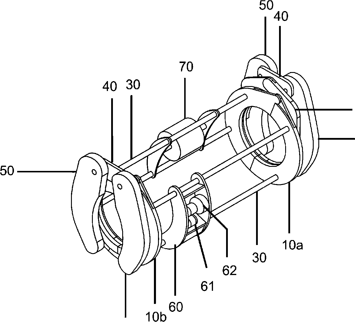
5/8 [019] A figura 1 apresenta a vista em perspectiva do equipamento para reparo de dutos.5/8 [019] Figure 1 shows the perspective view of the pipeline repair equipment.
[020] A figura 2 apresenta o equipamento para reparo de dutos com as estruturas anelares extremas (10a) e (10b) e as garras (50) abertas, de forma a manter a gaiola aberta para envolver a superfície externa do duto a ser reparado.[020] Figure 2 shows the equipment for repairing ducts with the extreme ring structures (10a) and (10b) and the claws (50) open, in order to keep the cage open to surround the external surface of the duct to be repaired .
[021] A figura 3 apresenta o atracamento do equipamento, com o fechamento das garras (50) na superfície do duto.[021] Figure 3 shows the mooring of the equipment, with the closing of the claws (50) on the surface of the duct.
[022] A figura 4A apresenta o equipamento para reparo de duto acoplado ao duto, a figura 4B apresenta a parte móvel do equipamento em rotação, a figura 4C apresenta o enrolamento do material de reparo na superfície do duto, a figura 4D apresenta a finalização de um ciclo de rotação da parte móvel do equipamento, a figura 4E apresenta a abertura das estruturas anelares extremas (10a) e (10b) e das garras (50) e a figura 4F apresenta a retirada do equipamento do entorno da superfície do duto.[022] Figure 4A shows the equipment for repairing the duct coupled to the duct, figure 4B shows the moving part of the equipment in rotation, figure 4C shows the winding of the repair material on the surface of the duct, figure 4D shows the completion of a rotation cycle of the mobile part of the equipment, figure 4E shows the opening of the extreme ring structures (10a) and (10b) and the claws (50) and figure 4F shows the removal of the equipment from around the duct surface.
DESCRICAO DETALHADA DA INVENÇÃO [023] Para os fins da presente invenção, o termo “material de reparo” (M) compreende qualquer material filamentar ou em forma de fita, misturado ou não com resina, a ser aplicado no perímetro da área danificada do duto (D).DETAILED DESCRIPTION OF THE INVENTION [023] For the purposes of the present invention, the term "repair material" (M) includes any filamentary or tape-like material, mixed or not with resin, to be applied to the perimeter of the damaged area of the duct (D).
[024] O equipamento para reparo de dutos, objeto da presente invenção, compreende um primeiro par de segmentos arqueados (10a) unidos entre si por meio de um conector disposto na porção superior (20a), e um segundo par de segmentos arqueados (10b) unidos entre si por meio de um conector na porção superior (20b), ditos pares de segmentos arqueados (10a) e (10b) que conformam uma estrutura anelar com abertura inferior, sendo no contexto da presente patente,[024] The pipeline repair equipment, object of the present invention, comprises a first pair of arcuate segments (10a) joined together by means of a connector arranged in the upper portion (20a), and a second pair of arcuate segments (10b) ) joined together by means of a connector in the upper portion (20b), said pairs of arcuate segments (10a) and (10b) that form an annular structure with lower opening, being in the context of the present patent,
Petição 870170006326, de 30/01/2017, pág. 10/44Petition 870170006326, of 01/30/2017, p. 10/44
6/8 para fim de simplificação, denominadas de primeira estrutura anelar (10a) e segunda estrutura anelar (10b).6/8 for simplification purposes, called the first ring structure (10a) and second ring structure (10b).
[025] A primeira estrutura anelar (10a) é posicionada paralela e distanciada da segunda estrutura anelar (10b), em cujas faces internas são fixadas as extremidades de hastes (30) alinhadas com a geratriz, conformando uma gaiola.[025] The first annular structure (10a) is positioned parallel to and distanced from the second annular structure (10b), on whose internal faces the ends of the rods (30) are aligned with the generatrix, forming a cage.
[026] As estruturas anelares (10a) e (10b) e a gaiola conformada pelas hastes (30) configuram a parte móvel do equipamento de reparo de dutos, acionada por unidade de controle, para rotação.[026] The ring structures (10a) and (10b) and the cage formed by the rods (30) configure the mobile part of the duct repair equipment, activated by a control unit, for rotation.
[027] Na face externa dos conectores (20a) e (20b) é mancalizada uma articulação (40) que une um par de segmentos arqueados que conformam uma garra articulada com abertura inferior (50) posicionada na face externa das estruturas anelares (10a) e (10b), ditas garras (50) fixas em relação à parte móvel do equipamento.[027] On the outer face of the connectors (20a) and (20b), a joint (40) that joins a pair of arched segments that form a hinged claw with a lower opening (50) positioned on the outer face of the ring structures (10a) and (10b), said claws (50) fixed in relation to the mobile part of the equipment.
[028] A abertura das estruturas anelares (10a) e (10b) é alinhada com a abertura das garras articuladas (50), sendo as operações de abertura e de fechamento das estruturas anelares (10a) e (10b) e das garras (50) realizada por uma unidade de controle.[028] The opening of the ring structures (10a) and (10b) is aligned with the opening of the articulated claws (50), with the opening and closing operations of the ring structures (10a) and (10b) and the claws (50 ) performed by a control unit.
[029] Pelo menos uma das hastes (30) apresenta pelo menos um carro móvel (60) que se desloca longitudinalmente entre a primeira estrutura anelar (10a) e a segunda estrutura anelar (10b), dito carro móvel (60) que traciona o material de reparo (M) disposto em pelo menos uma bobina (70) fixada em uma haste diametralmente oposta àquela de fixação do carro móvel (60).[029] At least one of the rods (30) has at least one movable carriage (60) that moves longitudinally between the first annular structure (10a) and the second annular structure (10b), said mobile carriage (60) that pulls the repair material (M) arranged on at least one coil (70) fixed on a rod diametrically opposite to that of the fixing of the mobile car (60).
[030] Uma unidade de controle unidade com suprimento hidráulico ou elétrico, operada local ou à distância, aciona os componentes elétricos e hidráulicos que promovem a rotação da parte móvel do equipamento,[030] A control unit unit with hydraulic or electric supply, operated locally or remotely, activates the electrical and hydraulic components that promote the rotation of the mobile part of the equipment,
Petição 870170006326, de 30/01/2017, pág. 11/44Petition 870170006326, of 01/30/2017, p. 11/44
7/8 bem como a abertura e fechamento das estruturas anelares extremas (10a) e (10b) e das garras (50) e o acionamento do carro móvel (60). [031] Para o posicionamento do equipamento na linha a ser recuperada, as estruturas anelares extremas (10a) e (10b) e as garras (50) são abertas, de forma a manter a gaiola aberta para envolver a superfície externa do duto (D) a ser reparado, conforme apresentado na figura 2.7/8 as well as the opening and closing of the extreme ring structures (10a) and (10b) and the claws (50) and the drive of the mobile car (60). [031] For the positioning of the equipment in the line to be recovered, the extreme ring structures (10a) and (10b) and the claws (50) are opened, in order to keep the cage open to envelop the external surface of the duct (D ) to be repaired, as shown in figure 2.
[032] Opcionalmente, o controle de abertura e de fechamento das estruturas anelares extremas (10a) e (10b) e das garras (50) é realizado à distância, sendo utilizado um guindaste ou similar para o posicionamento da gaiola no entorno do duto.[032] Optionally, the control of opening and closing of the extreme ring structures (10a) and (10b) and of the claws (50) is performed at a distance, using a crane or similar for positioning the cage around the duct.
[033] Para o atracamento do equipamento de reparo de duto ao duto, as garras (50) são fechadas de encontro ao perímetro da linha. Em seguida, as estruturas anelares (10a) e (10b) são fechadas, provendo o fechamento da gaiola junto ao perímetro da linha, conforme apresentado na figura 3.[033] For the docking of the repair equipment from duct to duct, the jaws (50) are closed against the perimeter of the line. Then, the ring structures (10a) and (10b) are closed, providing the closure of the cage near the perimeter of the line, as shown in figure 3.
[034] Identificado o fechamento das estruturas anelares extremas (10a) e (10b) e das garras (50) pela unidade de controle, é iniciado o giro da gaiola concêntrico à superfície do duto em reparo.[034] Once the closure of the extreme ring structures (10a) and (10b) and claws (50) has been identified by the control unit, the rotation of the concentric cage to the surface of the duct under repair is initiated.
[035] A extremidade do material de reparo disposto na bobina (70) é fixada no carro móvel (60) e tracionada pela polia (61), dito carro móvel (60) que se desloca entre as extremidades das hastes (30) de forma sincronizada com o giro da parte móvel do equipamento, depositando o material de reparo (M) tensionado sobre a superfície do duto sob a forma de helicóide.[035] The end of the repair material disposed on the coil (70) is fixed to the mobile carriage (60) and pulled by the pulley (61), said mobile carriage (60) which moves between the ends of the rods (30) in a way synchronized with the rotation of the mobile part of the equipment, depositing the repair material (M) tensioned on the surface of the duct in the form of a helicoid.
[036] O passo do helicoide é definido pela relação entre o giro da parte móvel do equipamento e o avanço do carro móvel (60) na haste (30), onde cada camada de material de reparo aplicado na superfície do duto[036] The helical pitch is defined by the relationship between the rotation of the mobile part of the equipment and the advance of the mobile car (60) on the rod (30), where each layer of repair material applied on the surface of the duct
Petição 870170006326, de 30/01/2017, pág. 12/44Petition 870170006326, of 01/30/2017, p. 12/44
8/8 equivale a um ciclo de deslocamento do carro móvel (60) as entre estruturas anelares (10a) e (10b).8/8 is equivalent to a cycle of displacement of the mobile car (60) between the ring structures (10a) and (10b).
[037] Opcionalmente, nas extremidades das hastes (30) é previsto um mecanismo de fim-de-curso (não representado) que inverte o sentido de avanço do carro móvel (60) na haste (30), permitindo o depósito de várias camadas de material de reparo (M).[037] Optionally, an end-of-stroke mechanism (not shown) is provided at the ends of the rods (30) that reverses the forward direction of the mobile carriage (60) on the rod (30), allowing the deposit of several layers repair material (M).
[038] O carro móvel (60) apresenta polias (61) que permitem o ajuste de tensão do material de reparo, operação preferentemente realizada de forma manual e sempre que a gaiola não estiver girando, e um mecanismo de freio (62) acionado à distância que imobiliza o carro móvel (60) na haste (30).[038] The mobile carriage (60) has pulleys (61) that allow the tension adjustment of the repair material, an operation preferably carried out manually and whenever the cage is not rotating, and a brake mechanism (62) activated at distance that immobilizes the mobile carriage (60) on the rod (30).
Petição 870170006326, de 30/01/2017, pág. 13/44Petition 870170006326, of 01/30/2017, p. 13/44
1/21/2
Claims (3)
Priority Applications (3)
| Application Number | Priority Date | Filing Date | Title |
|---|---|---|---|
| BR102017001908-0A BR102017001908A2 (en) | 2017-01-30 | 2017-01-30 | pipeline repair equipment |
| EP17894407.0A EP3575654B1 (en) | 2017-01-30 | 2017-12-19 | Equipment for repairing ducts |
| PCT/BR2017/050391 WO2018137012A1 (en) | 2017-01-30 | 2017-12-19 | Equipment for repairing ducts |
Applications Claiming Priority (1)
| Application Number | Priority Date | Filing Date | Title |
|---|---|---|---|
| BR102017001908-0A BR102017001908A2 (en) | 2017-01-30 | 2017-01-30 | pipeline repair equipment |
Publications (1)
| Publication Number | Publication Date |
|---|---|
| BR102017001908A2 true BR102017001908A2 (en) | 2018-08-14 |
Family
ID=62978806
Family Applications (1)
| Application Number | Title | Priority Date | Filing Date |
|---|---|---|---|
| BR102017001908-0A BR102017001908A2 (en) | 2017-01-30 | 2017-01-30 | pipeline repair equipment |
Country Status (3)
| Country | Link |
|---|---|
| EP (1) | EP3575654B1 (en) |
| BR (1) | BR102017001908A2 (en) |
| WO (1) | WO2018137012A1 (en) |
Families Citing this family (5)
| Publication number | Priority date | Publication date | Assignee | Title |
|---|---|---|---|---|
| GB2581469A (en) * | 2018-11-16 | 2020-08-26 | Pipeline Technique Ltd | Tape winding apparatus and method |
| CN110486568B (en) * | 2019-08-20 | 2021-10-22 | 北京安科管道工程科技有限公司 | Pretightening force repairing method, pretightening force and clamp combined repairing method and repaired pipeline |
| CN112473044B (en) * | 2020-12-04 | 2021-11-09 | 张琴 | A water pipe mount for reducing fire control intensity of labour that puts out a fire |
| CN112660946B (en) * | 2020-12-18 | 2023-05-16 | 湖北三江航天红阳机电有限公司 | Winding machine for packaging optical fibers on outer surface of pipeline |
| CN116293175A (en) * | 2021-12-20 | 2023-06-23 | 中国石油化工股份有限公司 | An auxiliary device for manual winding of pipes |
Family Cites Families (18)
| Publication number | Priority date | Publication date | Assignee | Title |
|---|---|---|---|---|
| AU650423B2 (en) | 1990-03-14 | 1994-06-23 | Norman C. Fawley | Method of and apparatus for reinforcing pipe |
| FR2666864B1 (en) * | 1990-09-14 | 1993-02-19 | Labiche Jean Pierre | METHOD FOR REPAIRING OR RESTORING ON-SITE A SECTION OF A PIPE OR ENCLOSURE INTENDED TO CONTAIN OR CONTAIN A PRESSURIZED FLUID, AND DEVICE FOR CARRYING OUT SAID METHOD. |
| BR9301685A (en) | 1993-04-28 | 1994-11-08 | Petroleo Brasileiro Sa | Method and system for submerged pipe repair operations |
| JP3309602B2 (en) * | 1994-11-25 | 2002-07-29 | 日本鋼管株式会社 | Automatic tape winding device |
| PL104774U1 (en) | 1996-05-28 | 1997-12-08 | Janusz Krasnicki | Appliance for massaging large muscular body portions |
| US5996216A (en) | 1998-07-02 | 1999-12-07 | Nextrom, Ltd. | Apparatus for applying soft filaments to continuous elongate articles |
| US6591046B2 (en) | 2001-06-06 | 2003-07-08 | The United States Of America As Represented By The Secretary Of The Navy | Method for protecting optical fibers embedded in the armor of a tow cable |
| US20060272724A1 (en) | 2005-04-26 | 2006-12-07 | Borland Robin N | System and method for pipe repair using fiber wrap and polymeric resin |
| ITMI20062503A1 (en) * | 2006-12-22 | 2008-06-23 | Geco System Spa | METHOD AND TOGETHER TO REPAIR JOINT OR IRON-TUBE PLASTIC TUBES |
| BRPI0706196A2 (en) * | 2007-06-29 | 2009-02-17 | Vitor Jose Frainer | Pipe repair method by reinforcement produced by winding monofilament or multifilament wires or cables around the pipe in the defect region |
| WO2011043837A1 (en) * | 2009-10-06 | 2011-04-14 | Bartell Machinery Systems, Llc | Mountable traversing carriage |
| WO2011049668A2 (en) * | 2009-10-20 | 2011-04-28 | Pipestream B.V. | Method and apparatus for reinforcing a pipeline |
| BRMU9000565U2 (en) | 2010-04-28 | 2012-01-10 | Gabriel Alejandro Tarnowski | machine for applying pipe repair by reinforcement produced by winding monofilament or multifilament wires or cables around the tube in the defect region |
| FR2991747B1 (en) * | 2012-06-08 | 2016-07-01 | 3X Eng | DEVICE AND METHOD FOR REPAIRING A LONGILINE BODY |
| CN103470910B (en) * | 2013-09-24 | 2015-09-16 | 湖北工业大学 | The online Stetch Wrapping Machine of a kind of pipeline |
| BR102013024532B8 (en) | 2013-09-25 | 2023-12-26 | Favaro Borges Marcelo | Method for repairing defects in rigid ducts through the application of a double gutter over the damaged region, positioned with interference and connected by intermittent union splints |
| BR102014002292B1 (en) | 2014-01-30 | 2022-03-29 | Petroleo Brasileiro S. A. - Petrobras | Production flexible duct repair method with split clamp and composite material |
| CN104191605B (en) * | 2014-07-25 | 2016-10-26 | 湖北工业大学 | A kind of petroleum transportation pipeline protection adhesive tape automatic winding apparatus |
-
2017
- 2017-01-30 BR BR102017001908-0A patent/BR102017001908A2/en not_active Application Discontinuation
- 2017-12-19 WO PCT/BR2017/050391 patent/WO2018137012A1/en not_active Ceased
- 2017-12-19 EP EP17894407.0A patent/EP3575654B1/en not_active Not-in-force
Also Published As
| Publication number | Publication date |
|---|---|
| EP3575654A1 (en) | 2019-12-04 |
| EP3575654A4 (en) | 2020-07-01 |
| WO2018137012A1 (en) | 2018-08-02 |
| EP3575654B1 (en) | 2022-09-21 |
Similar Documents
| Publication | Publication Date | Title |
|---|---|---|
| WO2018137012A1 (en) | Equipment for repairing ducts | |
| JP6547216B2 (en) | LINER FOR REINFORCING PIPE AND METHOD OF MANUFACTURING THE SAME | |
| US9310014B2 (en) | Systems and methods for making pipe, and method of installing the pipe in a pipeline | |
| US4496499A (en) | Process for lining high pressure pipeline | |
| EP2273171B1 (en) | Method of measuring a leak in a pipe | |
| BR112016025665B1 (en) | FLEXIBLE DUCT OF NON-ADHERENT LAYERS TO TRANSPORT AN ABRASIVE MATERIAL, METHOD FOR MANUFACTURING A FLEXIBLE DUCT OF NON-ADHERENT LAYERS TO TRANSPORT ABRASIVE MATERIAL AND USE OF A DUCT | |
| US20100078118A1 (en) | Repair and strengthening of small diameter pipes with frp laminates | |
| KR102058005B1 (en) | Photocurable maintenance and reinforcement method for superannuated pipes using prefabricated lightweight packer apparatus | |
| US4979296A (en) | Method for fabricating helical flowline bundles | |
| US7258141B2 (en) | Pipe liner apparatus and method | |
| NO20130379A1 (en) | Polymer multilayer tubes, apparatus for preparing the multilayer tubing and process for the same | |
| CN104520629B (en) | Lead to the fitted lining of the pipeline of offshore installations | |
| JPH05507331A (en) | Preforms, apparatus and methods for casing and/or lining cylinders | |
| EP3449091B1 (en) | Depressurisation method and apparatus for subsea equipment | |
| US10125910B2 (en) | Device for processing an elongate body | |
| CN104321489A (en) | Systems for refurbishment of tube wells | |
| BR112016024258B1 (en) | Method of installing and using a rigid pipe from a ship or floating platform and useful installation for carrying out such method | |
| KR102217237B1 (en) | Glass fiber tube for non-excavation repair and reinforcement of pipes using thermosetting resin and pipe repair and reinforcement method using the same | |
| BR112014030600B1 (en) | device, underwater vehicle and process for repairing a long body | |
| US10436350B1 (en) | Trenchless pipe-laying | |
| KR102058004B1 (en) | Prefabricated lightweight packer apparatus for maintenance and reinforcement of superannuated pipes | |
| KR102370702B1 (en) | Apparatus and method for repairing pipe | |
| KR102082492B1 (en) | Maintenance and reinforcement apparatus and method for decrepit water pipes using curing tube | |
| CN115199854A (en) | Lining soft pipe | |
| US7967030B2 (en) | Spliced long-length hose and method for splicing hoses |
Legal Events
| Date | Code | Title | Description |
|---|---|---|---|
| B03A | Publication of a patent application or of a certificate of addition of invention [chapter 3.1 patent gazette] | ||
| B06W | Patent application suspended after preliminary examination (for patents with searches from other patent authorities) chapter 6.23 patent gazette] | ||
| B15K | Others concerning applications: alteration of classification |
Free format text: AS CLASSIFICACOES ANTERIORES ERAM: B29C 63/14 , F16L 58/16 , F16L 59/10 , F16L 55/168 , F16L 55/18 , B65H 81/06 Ipc: F16L 1/024 (2006.01), F16L 55/18 (2006.01), F16L 5 |
|
| B07A | Application suspended after technical examination (opinion) [chapter 7.1 patent gazette] | ||
| B09B | Patent application refused [chapter 9.2 patent gazette] | ||
| B09B | Patent application refused [chapter 9.2 patent gazette] |
Free format text: MANTIDO O INDEFERIMENTO UMA VEZ QUE NAO FOI APRESENTADO RECURSO DENTRO DO PRAZO LEGAL |