BR102019021237A2 - maintenance platform for an agricultural machine and harvester for tall and stem plants - Google Patents
maintenance platform for an agricultural machine and harvester for tall and stem plants Download PDFInfo
- Publication number
- BR102019021237A2 BR102019021237A2 BR102019021237-3A BR102019021237A BR102019021237A2 BR 102019021237 A2 BR102019021237 A2 BR 102019021237A2 BR 102019021237 A BR102019021237 A BR 102019021237A BR 102019021237 A2 BR102019021237 A2 BR 102019021237A2
- Authority
- BR
- Brazil
- Prior art keywords
- machine
- maintenance platform
- agricultural machine
- chassis
- tilting floor
- Prior art date
Links
- 238000012423 maintenance Methods 0.000 title claims abstract description 43
- 240000000111 Saccharum officinarum Species 0.000 claims abstract description 30
- 235000007201 Saccharum officinarum Nutrition 0.000 claims abstract description 30
- 238000003306 harvesting Methods 0.000 claims abstract description 23
- 241000196324 Embryophyta Species 0.000 claims abstract description 16
- 235000011684 Sorghum saccharatum Nutrition 0.000 claims abstract description 9
- 244000138286 Sorghum saccharatum Species 0.000 claims description 4
- 240000006394 Sorghum bicolor Species 0.000 abstract description 5
- 238000004140 cleaning Methods 0.000 abstract description 5
- 239000012634 fragment Substances 0.000 description 14
- 239000010902 straw Substances 0.000 description 11
- 239000002699 waste material Substances 0.000 description 11
- 238000009825 accumulation Methods 0.000 description 7
- 238000005520 cutting process Methods 0.000 description 6
- 238000001816 cooling Methods 0.000 description 5
- 230000007246 mechanism Effects 0.000 description 5
- 238000012545 processing Methods 0.000 description 4
- 239000000428 dust Substances 0.000 description 3
- 238000003860 storage Methods 0.000 description 3
- 235000013311 vegetables Nutrition 0.000 description 3
- 239000011230 binding agent Substances 0.000 description 2
- 238000010276 construction Methods 0.000 description 2
- 230000000694 effects Effects 0.000 description 2
- 239000012530 fluid Substances 0.000 description 2
- 230000033001 locomotion Effects 0.000 description 2
- 235000011475 lollipops Nutrition 0.000 description 2
- 230000001737 promoting effect Effects 0.000 description 2
- 241001124569 Lycaenidae Species 0.000 description 1
- 230000009471 action Effects 0.000 description 1
- 230000005540 biological transmission Effects 0.000 description 1
- 235000013339 cereals Nutrition 0.000 description 1
- 239000004020 conductor Substances 0.000 description 1
- 238000011161 development Methods 0.000 description 1
- 238000007599 discharging Methods 0.000 description 1
- 230000010006 flight Effects 0.000 description 1
- 239000004459 forage Substances 0.000 description 1
- 239000011121 hardwood Substances 0.000 description 1
- 230000003993 interaction Effects 0.000 description 1
- 239000000463 material Substances 0.000 description 1
- 238000000034 method Methods 0.000 description 1
- 238000012986 modification Methods 0.000 description 1
- 230000004048 modification Effects 0.000 description 1
- 230000000737 periodic effect Effects 0.000 description 1
- 230000008569 process Effects 0.000 description 1
- 230000001681 protective effect Effects 0.000 description 1
- 230000008439 repair process Effects 0.000 description 1
- 239000002689 soil Substances 0.000 description 1
- 238000012546 transfer Methods 0.000 description 1
Images


Classifications
-
- A—HUMAN NECESSITIES
- A01—AGRICULTURE; FORESTRY; ANIMAL HUSBANDRY; HUNTING; TRAPPING; FISHING
- A01B—SOIL WORKING IN AGRICULTURE OR FORESTRY; PARTS, DETAILS, OR ACCESSORIES OF AGRICULTURAL MACHINES OR IMPLEMENTS, IN GENERAL
- A01B76/00—Parts, details or accessories of agricultural machines or implements, not provided for in groups A01B51/00 - A01B75/00
-
- A—HUMAN NECESSITIES
- A01—AGRICULTURE; FORESTRY; ANIMAL HUSBANDRY; HUNTING; TRAPPING; FISHING
- A01D—HARVESTING; MOWING
- A01D34/00—Mowers; Mowing apparatus of harvesters
- A01D34/01—Mowers; Mowing apparatus of harvesters characterised by features relating to the type of cutting apparatus
- A01D34/412—Mowers; Mowing apparatus of harvesters characterised by features relating to the type of cutting apparatus having rotating cutters
- A01D34/63—Mowers; Mowing apparatus of harvesters characterised by features relating to the type of cutting apparatus having rotating cutters having cutters rotating about a vertical axis
- A01D34/82—Other details
-
- A—HUMAN NECESSITIES
- A01—AGRICULTURE; FORESTRY; ANIMAL HUSBANDRY; HUNTING; TRAPPING; FISHING
- A01D—HARVESTING; MOWING
- A01D45/00—Harvesting of standing crops
-
- A—HUMAN NECESSITIES
- A01—AGRICULTURE; FORESTRY; ANIMAL HUSBANDRY; HUNTING; TRAPPING; FISHING
- A01D—HARVESTING; MOWING
- A01D45/00—Harvesting of standing crops
- A01D45/10—Harvesting of standing crops of sugar cane
Landscapes
- Life Sciences & Earth Sciences (AREA)
- Environmental Sciences (AREA)
- Engineering & Computer Science (AREA)
- Mechanical Engineering (AREA)
- Soil Sciences (AREA)
- Harvesting Machines For Specific Crops (AREA)
Abstract
plataforma de manutenção para uma máquina agrícola e máquina colhedora de plantas altas e cauleosas. a presente invenção refere-se a uma nova plataforma de manutenção particularmente desenvolvida para ser utilizada em máquinas agrícolas, tais como aquelas destinadas à colheita de plantas altas e cauleosas, como é o caso da cana-de-açúcar e sorgo, sendo configurada para melhorar as condições de limpeza no topo da máquina e, ainda, a segurança dos operadores e condutores. mais particularmente, a plataforma de manutenção da presente invenção é formada por uma estrutura de montagem (101) fixada ao chassi (12) da dita máquina (10), na qual é montado um assoalho basculante (110) através de um eixo de pivotamento (102) previsto em sua porção posterior e por um conjunto atuador (120) disposto em sua porção frontal, sendo que o referido conjunto atuador (120) compreende ao menos duas posições pré-definidas (p1, p2), onde na primeira posição (p1) o assoalho basculante (110) encontra-se inclinado em relação ao topo da máquina (10), e na segunda posição (p2) o assoalho basculante (110) está nivelado em relação ao topo da máquina (10).maintenance platform for an agricultural machine and harvester of tall and stem plants. the present invention refers to a new maintenance platform particularly developed to be used in agricultural machines, such as those destined to the harvest of tall and stem plants, as is the case of sugar cane and sorghum, being configured to improve the cleaning conditions at the top of the machine and also the safety of operators and drivers. more particularly, the maintenance platform of the present invention is formed by a mounting frame (101) fixed to the chassis (12) of said machine (10), on which a tilting floor (110) is mounted via a pivot axis ( 102) provided in its rear portion and by an actuator set (120) arranged in its front portion, and said actuator set (120) comprises at least two predefined positions (p1, p2), where in the first position (p1 ) the tilting floor (110) is inclined with respect to the top of the machine (10), and in the second position (p2) the tilting floor (110) is level with the top of the machine (10).
Description
[0001] A presente invenção refere-se, de um modo geral, a uma nova plataforma de manutenção particularmente desenvolvida para ser utilizada em máquinas agrícolas, tais como aquelas destinadas à colheita de plantas altas e cauleosas, como é o caso da cana-de-açúcar e sorgo-doce. Ainda, a presente invenção se refere a uma nova máquina de colher plantas altas e cauleosas a qual incorpora a plataforma de manutenção de modo a permitir a locomoção do operador e, ainda, melhorar as condições de limpeza no topo da máquina.[0001] The present invention refers, in general, to a new maintenance platform particularly developed to be used in agricultural machines, such as those intended for the harvest of tall and stem plants, such as in the case of sugarcane -sugar and sweet sorghum. Still, the present invention refers to a new machine for harvesting tall and stemmed plants which incorporates the maintenance platform in order to allow the operator to move around and also improve the cleaning conditions at the top of the machine.
[0002] De acordo com o estado da técnica, existem inúmeros modelos de máquinas e equipamentos agrícolas destinados a promover o aumento da produtividade nas colheitas dos diversos tipos de culturas vegetais, por exemplo, as colheitadeiras de grãos, as forrageiras e, também, as máquinas colhedoras das chamadas plantas altas e cauleosas, como é o caso da cana e do sorgo.[0002] According to the state of the art, there are numerous models of agricultural machinery and equipment designed to promote increased productivity in crops of different types of vegetable crops, for example, grain harvesters, forages and also the harvesting machines for so-called tall and stem plants, such as sugarcane and sorghum.
[0003] Essas máquinas colhedoras de plantas altas e cauleosas são projetadas e desenvolvidas para propiciar a colheita deste tipo específico de cultura, uma vez que, suas características intrínsecas exigem condições particulares para o seu adequado processamento, desde o corte das plantas até a transferência para os transbordos e/ou carretas.[0003] These harvesting machines for tall and stem plants are designed and developed to provide the harvest of this specific type of crop, since their intrinsic characteristics require particular conditions for their proper processing, from cutting the plants to transfer to transshipments and/or trucks.
[0004] Basicamente, como deve ser apreciado pelos técnicos no assunto, esse modelo de máquina destinada à colheita e processamento de plantas altas e cauleosas compreende uma estrutura relativamente alta, onde em seu topo são instalados alguns dos componentes da máquina, por exemplo, os trocadores de calor dos sistemas de arrefecimento, motores, bombas, etc., os quais exigem manutenções periódicas fazendo com que o operador suba e se desloque no topo da máquina para, então, realizar as devidas tarefas.[0004] Basically, as should be appreciated by technicians on the subject, this model of machine intended for harvesting and processing tall and stem plants comprises a relatively tall structure, where on its top some of the machine components are installed, for example, the heat exchangers for cooling systems, motors, pumps, etc., which require periodic maintenance by having the operator climb and move on top of the machine to then carry out the necessary tasks.
[0005] Dessa forma, conforme deve ser de conhecimento dos técnicos no assunto, o espaço para se movimentar no topo dessas máquinas é relativamente restrito, o que acaba dificultando até mesmo as tarefas mais simples de manutenções, além de colocar em risco a integridade dos operadores.[0005] Thus, as the technicians should be aware of, the space to move on top of these machines is relatively restricted, which ends up making even the simplest maintenance tasks difficult, in addition to jeopardizing the integrity of the operators.
[0006] Assim, no intuito de aumentar o espaço disponível para que os operadores se movimentem no topo das máquinas, foram desenvolvidos alguns modelos de plataformas de manutenção que são usualmente instaladas nas proximidades dos trocadores de calor dos sistemas de arrefecimento da dita máquina, e são fixadas de modo que o seu assoalho fique no mesmo plano do topo da máquina para, com isso, aumentar o espaço para que o operador se movimente e realize as manutenções necessárias com mais facilidade e segurança.[0006] Thus, in order to increase the space available for operators to move on top of the machines, some models of maintenance platforms were developed that are usually installed in the vicinity of the heat exchangers of the cooling systems of said machine, and they are fixed so that their floor is in the same plane as the top of the machine, thereby increasing the space for the operator to move and carry out the necessary maintenance more easily and safely.
[0007] No entanto, apesar de funcionais, essas plataformas revelam alguns inconvenientes gerados em razão de sua configuração e construção, que propicia o acúmulo de palha no topo das máquinas durante a operação, afetando e comprometendo o funcionamento de diversos componentes e mecanismos essenciais para o funcionamento da máquina. Particularmente, a título meramente exemplificativo, a palha acumulada no topo da máquina pode eventualmente obstruir as passagens de ar dos trocadores de calor dos sistemas de arrefecimento, afetando o funcionamento desses sistemas e, consequentemente, da máquina como um todo. Esse tipo de problema pode aumentar a necessidade de interrupções nos trabalhos e paradas da máquina para desobstruir essas passagens de ar ou, até mesmo, executar eventuais consertos em casos que ocorra algum dano nesse sistema, ou em qualquer outro componente, provocado por esse acúmulo de palha na região de topo da máquina.[0007] However, despite being functional, these platforms reveal some inconveniences generated due to their configuration and construction, which provides the accumulation of straw on top of the machines during operation, affecting and compromising the operation of various components and mechanisms essential for the functioning of the machine. Particularly, as an example, the straw accumulated on top of the machine can eventually obstruct the air passages of the heat exchangers of the cooling systems, affecting the operation of these systems and, consequently, of the machine as a whole. This type of problem can increase the need for work interruptions and machine stoppages to unclog these air passages or even carry out any repairs in cases where there is damage to this system, or any other component, caused by this accumulation of straw in the top region of the machine.
[0008] Em síntese, nota-se que o estado da técnica carece de soluções e alternativas para a construção das plataformas de manutenção de máquinas agrícolas capazes de obter uma área segura para os trabalhos dos operadores e condutores, mas principalmente impedir o acumulo de palha no topo da máquina, evitando, com isso, riscos de danificar eventuais sistemas e mecanismos que se encontram instados nesta região da máquina, como por exemplo, os trocadores de calor dos sistemas de arrefecimento, bombas, motores, etc. Como deve ser apreciado pelos técnicos no assunto, os modelos de plataformas conhecidos atualmente no estado da técnica não conseguem evitar o acúmulo de palha na região de topo da máquina, bem como o comprometimento das passagens de ar, comprometendo a produtividade das colheitas em virtude das paralizações da máquina para limpeza.[0008] In summary, it is noted that the state of the art lacks solutions and alternatives for the construction of agricultural machinery maintenance platforms capable of obtaining a safe area for the work of operators and conductors, but mainly to prevent the accumulation of straw on top of the machine, thus avoiding the risk of damaging any systems and mechanisms that are installed in this region of the machine, such as the heat exchangers of the cooling systems, pumps, motors, etc. As should be appreciated by technicians on the subject, the platform models currently known in the state of the art cannot prevent the accumulation of straw in the top region of the machine, as well as compromising the air passages, compromising the productivity of crops due to machine shutdowns for cleaning.
[0009] Dessa forma, apesar de se mostrarem funcionais até os dias de hoje, verificou-se que as plataformas para manutenções de máquinas agrícolas conhecidas e disponíveis no estado da técnica carecem de uma solução prática e funcional que proporcione uma área segura para que os operadores e condutores possam executar os processos de manutenção, mas principalmente consiga eliminar, ou minimamente reduzis, o acumulo de palha no topo dessas maquinas para, desse modo, reduzir a necessidade de paradas para limpeza do topo dessas máquinas. Assim, é importante frisar que são esses, dentre outros, os objetivos e soluções que se pretende obter com o desenvolvimento da presente invenção.[0009] Thus, despite being functional to this day, it was found that the platforms for maintenance of agricultural machines known and available in the state of the art lack a practical and functional solution that provides a safe area for the Operators and drivers can carry out the maintenance processes, but mainly be able to eliminate, or minimally reduce, the accumulation of straw on top of these machines, thereby reducing the need for stoppages to clean the top of these machines. Thus, it is important to emphasize that these are, among others, the objectives and solutions that are intended to be achieved with the development of the present invention.
[0010] Dessa forma, de acordo com o acima apresentado, a presente invenção tem por objetivo prover uma nova plataforma de manutenção para ser utilizada em máquinas agrícolas, particularmente aquelas destinadas à colheita de plantas altas e cauleosas, sendo essa plataforma projetada e desenvolvida para obter uma solução prática e funcional aos problemas, limitações e inconvenientes revelados pelas plataformas de manutenção conhecidas no estado da técnica.[0010] Thus, according to the above, the present invention aims to provide a new maintenance platform to be used in agricultural machines, particularly those intended for the harvest of tall and stem plants, this platform being designed and developed for obtain a practical and functional solution to the problems, limitations and inconveniences revealed by the maintenance platforms known in the state of the art.
[0011] Mais particularmente, é um dos objetivos da presente invenção prover uma plataforma de manutenção para máquinas agrícolas que compreende características técnicas, construtivas e funcionais capazes de evitar o acumulo de palha no topo das máquinas e, consequentemente, o comprometimento do funcionamento dos componentes instalados nessa região, o que torna possível reduzir a necessidade de paradas para limpeza e eventuais manutenções em decorrência desse acumulo de palha.[0011] More particularly, it is one of the objectives of the present invention to provide a maintenance platform for agricultural machines that comprises technical, constructive and functional characteristics capable of preventing the accumulation of straw on top of the machines and, consequently, compromising the functioning of the components installed in this region, which makes it possible to reduce the need for stops for cleaning and eventual maintenance due to this accumulation of straw.
[0012] Ainda outro objetivo da presente invenção é prover uma máquina colhedora, particularmente destinada à colheita de culturas vegetais altas e cauleosas, tais como a cana e o sorgo, que compreende um chassi sobre o qual é instalada uma plataforma de manutenção, conforme acima mencionada.[0012] Yet another objective of the present invention is to provide a harvesting machine, particularly intended for harvesting tall and stemmed vegetable crops, such as sugarcane and sorghum, which comprises a chassis on which a maintenance platform is installed, as above mentioned.
[0013] Dessa forma, para se conseguir obter os efeitos técnicos e funcionais acima sumarizados, dentre outros, a presente invenção refere-se a uma nova plataforma de manutenção para uma máquina agrícola que compreende uma estrutura de montagem fixada ao chassi da referida máquina, um assoalho basculante montado de modo pivotável na estrutura de montagem através de um eixo de pivotamento previsto em sua porção posterior e por um conjunto atuador previsto em sua porção frontal, sendo que o conjunto atuador possui ao menos duas posições pré-definidas, onde na primeira posição o referido assoalho basculante está inclinado em relação ao topo da máquina, enquanto que na segunda posição esse assoalho basculante fica nivelado em relação ao topo da máquina.[0013] Thus, in order to obtain the technical and functional effects summarized above, among others, the present invention refers to a new maintenance platform for an agricultural machine that comprises a mounting structure fixed to the chassis of said machine, a tilting floor mounted pivotally on the mounting structure through a pivot axis provided in its rear portion and by an actuator set provided in its front portion, the actuator set having at least two predefined positions, where in the first position said tilting floor is inclined with respect to the top of the machine, while in the second position said tilting floor is level with respect to the top of the machine.
[0014] Opcionalmente, segundo uma concretização possível da presente invenção, a estrutura de montagem compreende ao menos um braço de sustentação fixado ao referido chassi da máquina.[0014] Optionally, according to a possible embodiment of the present invention, the mounting structure comprises at least one support arm fixed to said machine chassis.
[0015] Em uma montagem particular da presente invenção, o assoalho basculante é dotado de uma extensão inferior. Mais particularmente, segundo uma configuração mais particular, essa extensão é disposta angularmente em relação ao assoalho basculante, de modo que, quando o conjunto atuador assume a primeira posição, a referida extensão fica disposta paralelamente ao chassi da máquina.[0015] In a particular arrangement of the present invention, the tilting floor is provided with a lower extension. More particularly, according to a more particular configuration, this extension is arranged angularly with respect to the tilting floor, so that, when the actuator assembly assumes the first position, said extension is arranged parallel to the chassis of the machine.
[0016] De acordo com realizações particulares da presente invenção, o conjunto atuador é formado por um eixo superior conectado de modo pivotável ao assoalho basculante, e um eixo inferior que é configurado para interagir com ao menos um suporte, sendo que esses eixos estão dispostos paralelamente entre si e conectados através de ao menos uma haste. Ainda, conforme uma outra concretização opcional, esse conjunto atuador possui duas hastes dispostas nas extremidades dos referidos eixos superior e inferior.[0016] According to particular embodiments of the present invention, the actuator assembly is formed by an upper axle pivotally connected to the tilting floor, and a lower axle that is configured to interact with at least one support, and these axles are arranged parallel to each other and connected through at least one rod. Still, according to another optional embodiment, this actuator assembly has two rods arranged at the ends of said upper and lower axes.
[0017] Alternativamente, conforme uma outra realização da presente invenção, o mencionado ao menos um suporte do conjunto atuador compreende pelo menos dois recessos. Ainda, de acordo com uma realização particular da presente invenção, esses recessos previstos no referido ao menos um suporte correspondem, respectivamente, às ditas posições pré-definidas de atuação da plataforma.[0017] Alternatively, according to another embodiment of the present invention, said at least one support of the actuator assembly comprises at least two recesses. Still, according to a particular embodiment of the present invention, these recesses provided in said at least one support correspond, respectively, to said pre-defined actuation positions of the platform.
[0018] Também, de acordo com uma realização da presente invenção, o referido conjunto atuador (120) compreende dois suportes (123) dispostos nas laterais da estrutura de montagem da plataforma de manutenção.[0018] Also, according to an embodiment of the present invention, said actuator assembly (120) comprises two supports (123) arranged on the sides of the mounting structure of the maintenance platform.
[0019] Também, conforme algumas concretizações possíveis da presente invenção, o conjunto atuador compreende componentes mecânicos, hidráulicos, pneumáticos, elétricos e eletrônicos, como pistões, molas, amortecedores, válvulas, eletroválvulas.[0019] Also, according to some possible embodiments of the present invention, the actuator assembly comprises mechanical, hydraulic, pneumatic, electrical and electronic components, such as pistons, springs, dampers, valves, electrovalves.
[0020] Adicionalmente, e conforme acima comentado, a presente invenção refere-se também a uma máquina colhedora de plantas altas e cauleosas que compreende um chassi montado sobre rodas ou esteiras, um motor, uma cabine de operador, sendo que a referida máquina possui, ainda, ao menos uma plataforma de manutenção, conforme definida acima, montada e instalada junto ao seu chassi.[0020] Additionally, and as commented above, the present invention also relates to a harvester machine for tall and stemmed plants that comprises a chassis mounted on wheels or tracks, an engine, an operator cabin, and said machine has , also, at least one maintenance platform, as defined above, assembled and installed next to its chassis.
[0021] De acordo com concretizações possíveis da presente invenção, a referida máquina é configurada para executar a colheita de cana-de-açúcar e/ou sorgo-doce.[0021] According to possible embodiments of the present invention, said machine is configured to perform the harvest of sugar cane and/or sweet sorghum.
[0022] As características, vantagens e efeitos técnicos da presente invenção serão mais bem compreendidos por um técnico no assunto a partir da descrição detalhada a seguir, feita a título meramente exemplificativo, e não restritivo, de realizações da invenção, e com referência às figuras anexas, as quais:
A Figura 1 é uma vista lateral esquemática de uma máquina colhedora de cana e sorgo, tal como aquelas conhecidas no estado da técnica;
A Figura 2A e 2B são vistas em perspectiva traseira do chassi de uma máquina colhedora compreendendo a plataforma de manutenção, de acordo com a presente invenção, na posição desmontada e montada, respectivamente;
As Figuras 3A e 3B mostram, respectivamente, uma vista em perspectiva e uma vista lateral da plataforma de manutenção segundo a presente invenção, na posição desmontada; e
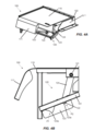
As Figuras 4A e 4B mostram, respectivamente, uma vista em perspectiva e uma vista lateral da plataforma de manutenção segundo a presente invenção, na posição montada.[0022] The characteristics, advantages and technical effects of the present invention will be better understood by a person skilled in the art from the following detailed description, given merely as an example, and not restrictive, of embodiments of the invention, and with reference to the figures attached, which:
Figure 1 is a schematic side view of a cane and sorghum harvesting machine, such as those known in the state of the art;
Figure 2A and 2B are rear perspective views of the chassis of a harvester machine comprising the maintenance platform, according to the present invention, in the disassembled and assembled position, respectively;
Figures 3A and 3B show, respectively, a perspective view and a side view of the maintenance platform according to the present invention, in the disassembled position; and
Figures 4A and 4B show, respectively, a perspective view and a side view of the maintenance platform according to the present invention, in the assembled position.
[0023] A invenção será agora descrita com relação às suas realizações particulares, fazendo-se referência às figuras anexas. Tais figuras são esquemáticas, e suas dimensões e/ou proporções podem não corresponder à realidade, uma vez que visam descrever a invenção de forma didática. Ademais, certos detalhes construtivos conhecidos e comuns podem ter sido omitidos para maior clareza e concisão da descrição que é feita a seguir. Os números de referência utilizados são repetidos ao longo das figuras para identificar partes idênticas ou semelhantes. Os termos eventualmente utilizados como “acima”, “abaixo”, “frente”, “trás”, “direita”, “esquerda” etc. e suas variantes devem ser interpretados segundo a orientação dada na Figura 1.[0023] The invention will now be described with respect to its particular embodiments, with reference to the attached figures. Such figures are schematic, and their dimensions and/or proportions may not correspond to reality, as they aim to describe the invention in a didactic way. Furthermore, certain known and common constructive details may have been omitted for clarity and conciseness from the description that follows. Reference numbers used are repeated throughout the figures to identify identical or similar parts. The terms eventually used such as “above”, “below”, “front”, “back”, “right”, “left” etc. and its variants should be interpreted according to the guidance given in Figure 1.
[0024] Os termos aqui empregados como colheitadeira, colhedora, máquina de colher e suas variantes são utilizados indistintamente para indicar uma máquina agrícola destinada à colheita de uma cultura vegetal e, no caso desta descrição, à colheita de plantas altas e cauleosas, tal como a cana-deaçúcar, a cana energia, o sorgo etc.[0024] The terms used herein such as combine harvester, harvester, harvesting machine and their variants are used interchangeably to indicate an agricultural machine intended for the harvest of a vegetable culture and, in the case of this description, for the harvest of tall and stem plants, such as sugar cane, energy cane, sorghum, etc.
[0025] Com relação agora aos desenhos, a Figura 1 ilustra uma vista lateral de uma realização de uma máquina agrícola 10 de acordo com aspectos conhecidos no estado da técnica. Conforme foi mostrado, a máquina 10 é configurada como uma colheitadeira de cana-de-açúcar. Entretanto, em outras realizações, essa máquina 10 pode corresponder a qualquer modelo de colheitadeira agrícola adequada conhecida do estado da técnica.[0025] Turning now to the drawings, Figure 1 illustrates a side view of an embodiment of an
[0026] Ainda com relação à Figura 1, a máquina 10 inclui um chassi 12, um par de rodas frontais 14, um par de rodas traseiras 16, e uma cabine de operador 18. A máquina 10 pode também incluir uma fonte primária de energia (por exemplo, um motor montado no chassi 12) que energiza um ou ambos pares de rodas 14, 16 por meio de uma transmissão (não mostrada). Alternativamente, a máquina 10 pode ser uma colheitadeira acionada sobre esteiras e, portanto, pode incluir esteiras acionadas pelo mecanismo motor em substituição às rodas ilustradas 14, 16. O mecanismo motor pode também acionar uma bomba de fluido hidráulico (não mostrada) configurada para gerar fluido hidráulico pressurizado para acionar vários componentes hidráulicos da máquina 10, inclusive as rodas ou esteiras.[0026] Still referring to Figure 1,
[0027] Adicionalmente, a máquina 10 pode incluir vários componentes para cortar, processar, limpar e descarregar cana-de-açúcar conforme a cana é colhida de um campo agrícola 20. Por exemplo, a máquina 10 pode incluir um conjunto de cortador de pontas 22 posicionado na sua extremidade frontal para interceptar a cana-de-açúcar conforme a máquina 10 se movimenta na direção de avanço, tal como indicado pela seta “X” na Figura 1. Conforme mostrado, o conjunto de cortador de pontas 22 pode incluir tanto um disco aglutinador 24 quanto um disco cortador 26. O disco aglutinador 24 pode ser configurado para aglutinar caules de cana-de-açúcar, de modo que o disco cortador 26 possa ser usado para cortar a ponta de cada caule. Geralmente, a altura do conjunto cortador de pontas 22 pode ser ajustável por meio de um par de braços 28 hidraulicamente erguidos e baixados, conforme desejado pelo operador.[0027] Additionally,
[0028] Adicionalmente, a colheitadeira 10 pode incluir um divisor de linhas 30 que se estende para cima e para trás a partir do campo 20. Em geral, o divisor de linhas 30 pode incluir dois rolos de alimentação em espiral 32, também conhecidos como “pirulito”. Cada rolo de alimentação 32 pode incluir uma sapata de solo 34, visto que sua extremidade inferior auxilia o divisor de linhas 30 separando os caules de cana-de-açúcar para colheita. Além disso, conforme mostrado na Figura 1, a colheitadeira 10 pode incluir um rolo tombador 36 posicionado próximo às rodas frontais 14 e um rolo com projeções 38 posicionado atrás do rolo tombador 36. Conforme o rolo tombador 36 é girado, os caules de cana-de-açúcar colhidos são tombados enquanto o divisor de linhas 30 aglutina os caules do campo agrícola 20 no sentido para o interior da máquina 10. Adicionalmente, conforme mostrado na Figura 1, o rolo com projeções 38 pode incluir uma pluralidade de aletas 40 intermitentemente montadas que auxiliam em forçar os caules de cana-de-açúcar para baixo. Conforme o rolo 38 é girado durante a colheita, os caules de cana-de-açúcar que foram tombados pelo rolo tombador 36 são separados e, posteriormente, tombados pelo rolo 38 conforme a máquina 10 continua a ser movida para frente com relação ao campo 20.[0028] Additionally, the
[0029] Ainda com referência à Figura 1, a máquina 10 pode também incluir um conjunto de corte de base 42 posicionado atrás do rolo 38. Como é geralmente entendido, o conjunto de corte de base 42 pode incluir lâminas (não mostradas) para cortar os caules de cana-de-açúcar conforme a cana é colhida. As lâminas, localizadas na periferia do conjunto 42, podem ser giradas por um motor hidráulico (não mostrado) acionado pelo sistema hidráulico da máquina. Adicionalmente, em diversas realizações, as lâminas podem ser anguladas para baixo para cortar a base da cana-de-açúcar conforme a cana é tombada pelo rolo 38.[0029] Still referring to Figure 1,
[0030] Além disso, como representado na Figura 1, a máquina 10 pode incluir um conjunto de um ou mais rolos transportadores 44 localizado a jusante do conjunto de corte de base 42 para mover os caules cortados de cana-deaçúcar a partir do conjunto de corte de base 42 ao longo da trajetória de processamento. Conforme mostrado na Figura 1, o conjunto de rolo transportadores 44 pode incluir uma pluralidade de rolos inferiores 46 e uma pluralidade de rolos superiores 48. Conforme a cana-de-açúcar é transportada através do conjunto de rolos transportadores 44, resíduos (por exemplo, pedras, sujeira e/ou similares) podem ser também transportados ou cair através dos rolos inferiores 46 sobre o campo 20.[0030] Furthermore, as depicted in Figure 1, the
[0031] Adicionalmente, como é possível observar na Figura 1, a máquina 10 pode incluir um conjunto picador 50 localizado na extremidade a jusante do conjunto de rolo transportadores 44 (por exemplo, adjacente aos rolos transportadores inferiores e superiores mais traseiros 46, 48). Em geral, o conjunto picador 50 pode ser usado para cortar ou picar os caules colhidos de cana-de-açúcar em pedaços ou “fragmentos” 51 menores que podem, por exemplo, medir 15,24 centímetros (seis (6) polegadas), também chamados de toletes ou rebolos. Os fragmentos 51 podem, então, ser impulsionados na direção de um conjunto elevador 52 da máquina 10 para serem coletados em um receptor externo ou dispositivo de armazenamento (não mostrado), por exemplo, os transbordos e caçambas.[0031] Additionally, as can be seen in Figure 1, the
[0032] Conforme é geralmente entendido, pedaços de resíduos 53 (por exemplo, poeira, sujeita, folhas, etc.) separados dos fragmentos de cana-deaçúcar 51 podem ser expelidos da máquina 10 através de um extrator primário 54, que é localizado atrás do conjunto picador 50 e é orientado para direcionar os resíduos 53 para fora da máquina 10. Adicionalmente, um ventilador 56 pode ser montado no extrator primário 54 para gerar uma força de sucção ou vácuo suficiente para capturar os resíduos 53 e forçar esses resíduos 53 através do extrator primário 54. Os resíduos 53 são, então, direcionados para fora e geralmente na direção contrária da máquina 10 por meio de uma saída do extrator primário 54. Os fragmentos separados 51 e mais pesados que os resíduos 53 que estão sendo expulsos pelo extrator 54, podem, então, cair para o conjunto elevador 52.[0032] As is generally understood, pieces of waste 53 (e.g. dust, dirt, leaves, etc.) separated from the sugar cane fragments 51 can be expelled from the
[0033] De acordo com este relatório descritivo, o conjunto elevador 52 deve ser entendido como compreendendo, em geral, uma estrutura de alojamento de elevador 58 e um elevador 60 que se estende dentro da referida estrutura de alojamento do elevador 58 entre uma extremidade proximal inferior 62 e uma extremidade distal superior 64. A extremidade proximal inferior 62 sendo fixada à máquina 10 e a extremidade distal superior 64 tendo uma abertura 82 para descarga do material colhido.[0033] According to this descriptive report, the elevator assembly 52 is to be understood as comprising, in general, an
[0034] Em realizações adicionais ou alternativas, o elevador 60 pode incluir uma corrente ou esteira transportadora 66 e uma pluralidade de pás ou taliscas 68 acopladas ou espaçadas de maneira uniforme na corrente 66. As taliscas 68 podem ser configuradas para segurar os fragmentos de cana-deaçúcar 51 no elevador 60 conforme os fragmentos 51 são elevados até a porção superior 70 do elevador 60. Adicionalmente, o elevador 60 pode incluir rodas dentadas inferiores e superiores 72, 74 posicionadas em torno das extremidades proximal e distal 62, 64, respectivamente. Conforme mostrado na Figura 1, um motor de elevador 76 pode ser acoplado a uma das rodas dentadas (por exemplo, a roda dentada superior 74) para acionar a corrente 66, permitindo assim que a corrente 66 e as taliscas 68 viajem em um ciclo sem fim entre as extremidades proximal e distal 62, 64 do elevador 60.[0034] In additional or alternative embodiments,
[0035] Além disso, pedaços de resíduos 53 (por exemplo, poeira, sujeira, folhas, etc.) separados dos fragmentos de cana-de-açúcar 51 podem ser expelidos da máquina 10 através de um extrator secundário 78 acoplado à extremidade traseira da estrutura de alojamento do elevador 58. Conforme mostrado na Figura 1, o extrator secundário 78 pode estar situado de maneira adjacente à extremidade distal 64 do elevador 60 e pode ser orientado para direcionar os resíduos 53 para fora a partir da máquina 10. Adicionalmente, um ventilador 80 pode ser montado no extrator secundário 78 para gerar uma força de sucção ou vácuo suficiente para extrair os resíduos 53 e forçar esses resíduos 53 através do extrator secundário 78. Os fragmentos separados 51, mais pesados que os resíduos 53 expelidos através do extrator 78, podem, então, cair da extremidade distal 64 do elevador 60. Tipicamente, os fragmentos 51 podem cair através de uma abertura de descarga 82 do conjunto elevador 52 em um dispositivo de armazenamento externo (não mostrado), tal como um carro, um transbordo, uma caçamba etc.[0035] In addition, pieces of waste 53 (eg dust, dirt, leaves, etc.) separated from the sugar cane fragments 51 can be expelled from the
[0036] Durante a operação, a máquina 10 é percorrida por todo o campo agrícola 20 para colher cana-de-açúcar ou qualquer outra planta alta e cauleosa. Após a altura do cortador de pontas 22 ser ajustada (se for utilizado) por meio dos braços 28, o disco aglutinador 24 no conjunto de cortador de pontas 22 pode funcionar de maneira a aglutinar as pontas de cana-de-açúcar conforme a máquina 10 procede através do campo 20, enquanto o disco cortador 26 corta as pontas folhosas dos caules de cana-de-açúcar para despejá-las ao longo de ambos os lados da máquina 10. Conforme os caules entram no divisor de linha 30, as sapatas 34 podem configurar a largura da operação para determinar a quantidade de cana-de-açúcar que entra na garganta da máquina 10, seja de modo fixo ou ajustável. Os pirulitos 32 aglutinam então os caules na entrada da máquina para permitir que o rolo tombador 36 curve os caules para baixo em conjunto com a ação do rolo alimentador 38. Uma vez que os caules são posicionados em ângulo conforme mostrado na Figura 1, o conjunto de corte de base 42 pode, então, cortar a base dos caules do campo 20. Os caules cortados são, então, direcionados ao conjunto de rolos transportadores 44.[0036] During operation, the
[0037] Os caules cortados de cana-de-açúcar são transportados para trás pelos rolos transportadores 46, 48 que comprimem os caules e a matéria colhida. Na extremidade a jusante do conjunto de rolos transportadores 44, o conjunto picador 50 corta ou pica os caules compactados de cana-de-açúcar em pedaços ou fragmentos 51. Resíduos transportados 53 (por exemplo, poeira, sujeira, folhas, etc.) separados dos fragmentos de cana-de-açúcar 51 são, então, extraídos através do extrator primário 54 usando a sucção criada pelo ventilador 56. Os fragmentos separados/lavados 51 caem, então, para o conjunto elevador 52 e viajam para cima por meio do elevador 60 a partir da sua extremidade proximal 62 até a extremidade distal 64. Durante a operação normal, uma vez que os fragmentos 51 alcançam a extremidade distal 64 do elevador 60, os fragmentos 51 caem através da abertura de descarga 82 até um dispositivo de armazenamento externo. Similar ao extrator primário 54, resíduos são soprados para fora da máquina 10 através do extrator secundário 78 com o auxílio do ventilador de extrator 80.[0037] The cut sugar cane stalks are transported backwards by the
[0038] Uma máquina colhedora 10, tal como descrita acima, pode ser, por exemplo, uma máquina conhecida no estado da técnica, tal como a colheitadeira de cana produzida pela CNH Industrial N.V. e comercializada com a marca Case IH.[0038] A
[0039] Dessa forma, com base no acima relatado, e com referência as demais figuras, observa-se que a plataforma de manutenção 100, de acordo com a presente invenção, é formada por uma estrutura de montagem 101 que é fixada ao chassi 12, e na qual é montado um assoalho basculante 110 através de um eixo de pivotamento 102 previsto em sua porção posterior e por um conjunto atuador 120 previsto em sua porção frontal, sendo que esse conjunto atuador 120 compreende ao menos duas posições pré-definidas (P1 e P2) que correspondem, respectivamente, às condições desmontada e montada da presente plataforma de manutenção 100. Mais particularmente, estas posições pré-definidas são configuradas para que na primeira posição (P1) o referido assoalho basculante 110 encontra-se inclinado a partir do topo da máquina 10, enquanto na segunda posição (P2) o referido assoalho basculante 110 encontrase nivelado ao topo da máquina 10.[0039] Thus, based on the above, and with reference to the other figures, it is observed that the
[0040] Opcionalmente, segundo uma concretização possível de montagem da presente invenção, e dependendo da configuração do chassi 12 da máquina 10, a estrutura de montagem 101 pode compreender ao menos um braço de sustentação 103, fixado ao chassi 12, tendo por finalidade promover o aumento da resistência e estabilidade da presente plataforma de manutenção 100.[0040] Optionally, according to a possible assembly embodiment of the present invention, and depending on the configuration of the
[0041] Em uma montagem particular da presente invenção, o referido assoalho basculante 110 pode compreender uma extensão inferior 111 que pode ser, segundo uma configuração mais particular, disposta angularmente em relação ao referido assoalho basculante 110, de modo a formar uma espécie de aba protetora, quando a plataforma de manutenção 100 encontra-se na condição desmontada, que acaba assumindo uma configuração paralela ao chassi 12 para, com isso, evitar que a palha entre na região abaixo do assoalho basculante 110 e fique em contato com os componentes instalados abaixo da plataforma de manutenção 100.[0041] In a particular arrangement of the present invention, said tilting
[0042] De acordo com realizações particulares da presente invenção, o referido conjunto atuador 120 é formado por um eixo superior 121, conectado de modo pivotável ao assoalho basculante 110, e um eixo inferior 122, o qual interage com ao menos um suporte 123, sendo que ambos os eixos 121 e 122 são dispostos paralelamente e conectados através de ao menos uma haste 124 e, mais particularmente por duas hastes 124 dispostas nas extremidades dos referidos eixos 121, 122. Mais particularmente, o referido ao menos um suporte 123 compreende pelo menos dois recessos 123a, os quais estabelecem as posições pré-definidas (P1, P2) através da interação com o referido eixo inferior 122.[0042] According to particular embodiments of the present invention, said
[0043] Segundo uma outra concretização opcional da presente invenção, o conjunto atuador 120 compreende dois suportes 123 dispostos nas laterais da estrutura de montagem 101, o que permite aumentar a capacidade de carga, mas principalmente melhorar a estabilidade da plataforma de manutenção 100, principalmente quando a mesma se encontra na condição montada.[0043] According to another optional embodiment of the present invention, the
[0044] Alternativamente, conforme uma outra realização da presente invenção, o referido conjunto atuador 120 pode compreender mecanismos mais sofisticados e automatizados para facilitar a movimentação do referido assoalho basculante entre a posição desmontada e montada. Por exemplo, o conjunto atuador 120 pode compreender componentes mecânicos, hidráulicos, pneumáticos, elétricos e eletrônicos, como pistões, molas, amortecedores, válvulas, eletroválvulas, etc. os quais são capazes de promover a movimentação das hastes 124 com o eixo inferior 122 entre as posições pré-definidas (P1, P2) determinadas pelo ao menos um suporte 123.[0044] Alternatively, according to another embodiment of the present invention, said
[0045] Dessa forma, como deve ser apreciado pelos técnicos no assunto, as posições (P1, P2) são definidas quando as extremidades do eixo inferior 122 são ancoradas nos respectivos recessos 123a dos ditos suportes 123, sendo que a primeira posição (P1), onde o assoalho basculante 110 encontra-se inclinada, é voltada para quando a máquina 10 está em operação em campo e, nessa posição, torna-se possível assegurar que a palha, proveniente por exemplo do cortador de pontas 22 da máquina, deslize sobre o assoalho basculante 110 e seja direcionada para o campo, impedindo que a palha fique acumulada no topo da máquina e, com isso, evita-se a obstrução das passagens de ar dos trocadores de calor do sistema de arrefecimento, por exemplo. Por outro lado, a segunda posição (P2), onde o assoalho basculante 110 encontrase nivelado ao topo da referida máquina 10, é voltada para quando a máquina está parada e o operador necessita fazer alguma intervenção nos componentes instalados no topo da referida máquina, provendo um maior espaço para que o operador se movimente com segurança.[0045] Thus, as should be appreciated by experts in the field, the positions (P1, P2) are defined when the ends of the
[0046] Adicionalmente, e conforme acima comentado, a presente invenção refere-se também a uma máquina colhedora de plantas altas e cauleosas que compreende um chassi 12 montado sobre rodas (14, 16) ou esteiras, um motor, uma cabine de operador (18), sendo que na região de topo do referido chassi 12 é instalada uma plataforma de manutenção 100 configurada de acordo com as características da invenção acima definida, de modo que a referida plataforma pode assumir ao menos duas posições prédefinidas (P1, P2), nas quais a primeira posição (P1) determina que o assoalho basculante 110 da referida plataforma 100 esteja inclinado a partir do topo da máquina 10, e a segunda posição (P2) determina que o referido assoalho basculante 110 esteja nivelado com o topo da máquina 10.[0046] Additionally, and as commented above, the present invention also relates to a harvester machine for tall and stemmed plants that comprises a
[0047] De acordo com concretizações possíveis da presente invenção, a referida máquina colhedora de plantas altas e cauleosas é projetada e desenvolvida para executar a colheita de cana-de-açúcar e/ou sorgo-doce.[0047] According to possible embodiments of the present invention, said harvester machine for tall and stemmed plants is designed and developed to perform the harvest of sugarcane and/or sweet sorghum.
[0048] Por fim, diante de todo o acima exposto, vale ressaltar que a presente descrição tem como objetivo apenas apresentar e definir de modo exemplificativo realizações da plataforma de manutenção e da máquina colhedora, de acordo com os objetos da presente invenção. Logo, como bem devem apreciar os técnicos no assunto, diversas modificações e combinações de elementos e detalhes equivalentes são possíveis sem, com isso, fugir do escopo de proteção definido pelas reivindicações anexas.[0048] Finally, in view of all of the above, it is noteworthy that the present description aims only to present and define, as an example, realizations of the maintenance platform and the harvesting machine, according to the objects of the present invention. Therefore, as experts in the field should appreciate, several modifications and combinations of elements and equivalent details are possible without, therefore, escaping from the scope of protection defined by the attached claims.
Claims (12)
uma estrutura de montagem (101) fixada ao chassi (12) da dita máquina (10);
um assoalho basculante (110) montado de modo pivotável na dita estrutura de montagem (101) através de um eixo de pivotamento (102) previsto em sua porção posterior e por um conjunto atuador (120) disposto em sua porção frontal;
sendo que o dito conjunto atuador (120) compreende ao menos duas posições pré-definidas (P1, P2), onde na primeira posição (P1) o dito assoalho basculante (110) está inclinado em relação ao topo da máquina (10), enquanto que na segunda posição (P2) o dito assoalho basculante (110) está nivelado em relação ao topo da máquina (10).MAINTENANCE PLATFORM FOR AN AGRICULTURAL MACHINE, characterized by the fact that it comprises:
a mounting frame (101) fixed to the chassis (12) of said machine (10);
a tilting floor (110) pivotally mounted on said mounting structure (101) through a pivot axis (102) provided in its rear portion and by an actuator assembly (120) disposed in its front portion;
wherein said actuator assembly (120) comprises at least two predefined positions (P1, P2), where in the first position (P1) said tilting floor (110) is inclined in relation to the top of the machine (10), while that in the second position (P2) said tilting floor (110) is level with the top of the machine (10).
Priority Applications (3)
| Application Number | Priority Date | Filing Date | Title |
|---|---|---|---|
| BR102019021237-3A BR102019021237B1 (en) | 2019-10-09 | MAINTENANCE PLATFORM FOR AN AGRICULTURAL MACHINE AND A HARVESTING MACHINE FOR TALL AND STEAKY PLANTS | |
| CN202080070782.XA CN114929010A (en) | 2019-10-09 | 2020-10-08 | Maintenance platform for agricultural machinery and harvester for high stem plants |
| PCT/BR2020/050402 WO2021068049A1 (en) | 2019-10-09 | 2020-10-08 | Maintenance platform for an agricultural machine and machine for harvesting tall, stemmed plants |
Applications Claiming Priority (1)
| Application Number | Priority Date | Filing Date | Title |
|---|---|---|---|
| BR102019021237-3A BR102019021237B1 (en) | 2019-10-09 | MAINTENANCE PLATFORM FOR AN AGRICULTURAL MACHINE AND A HARVESTING MACHINE FOR TALL AND STEAKY PLANTS |
Publications (2)
| Publication Number | Publication Date |
|---|---|
| BR102019021237A2 true BR102019021237A2 (en) | 2021-04-20 |
| BR102019021237B1 BR102019021237B1 (en) | 2024-09-10 |
Family
ID=
Cited By (1)
| Publication number | Priority date | Publication date | Assignee | Title |
|---|---|---|---|---|
| US12349630B2 (en) | 2022-04-06 | 2025-07-08 | Deere & Company | Elevator spreader conveyor system |
Cited By (1)
| Publication number | Priority date | Publication date | Assignee | Title |
|---|---|---|---|---|
| US12349630B2 (en) | 2022-04-06 | 2025-07-08 | Deere & Company | Elevator spreader conveyor system |
Also Published As
| Publication number | Publication date |
|---|---|
| CN114929010A (en) | 2022-08-19 |
| WO2021068049A1 (en) | 2021-04-15 |
Similar Documents
| Publication | Publication Date | Title |
|---|---|---|
| WO2022016249A1 (en) | Independent front platform for agricultural machines and agricultural harvester | |
| BR102019010532B1 (en) | STRUCTURAL CHASSIS FOR ASSEMBLING AN AGRICULTURAL MACHINE AND HARVESTING MACHINE | |
| WO2021068049A1 (en) | Maintenance platform for an agricultural machine and machine for harvesting tall, stemmed plants | |
| WO2019165527A1 (en) | Elevator assembly for a harvesting machine and harvesting machine | |
| BR102019021237B1 (en) | MAINTENANCE PLATFORM FOR AN AGRICULTURAL MACHINE AND A HARVESTING MACHINE FOR TALL AND STEAKY PLANTS | |
| BR102024008234A2 (en) | Mounting structure of the tipping roller and roller with projections of an agricultural combine harvester and agricultural combine harvester. | |
| BR102022025377A2 (en) | STRUCTURAL ASSEMBLY OF CONVEYOR ROLLER FOR AN AGRICULTURAL HARVESTING AND HARVESTING MACHINE | |
| BR102023016207A2 (en) | LIFTING ROLLER FOR AGRICULTURAL MACHINERY AND AGRICULTURAL HARVESTER | |
| WO2021016689A1 (en) | Chopper roller and chopper assembly for an agricultural machine and machine for harvesting tall, stemmed plants | |
| US12490676B2 (en) | Locking mechanism for the suspension assembly of a harvester and agricultural harvester | |
| WO2023235952A1 (en) | Protector for the elevator assembly of a harvesting machine, elevator assembly for a harvesting machine and agricultural harvester | |
| BR102022005071A2 (en) | MOVEMENT SYSTEM FOR THE LIFT ASSEMBLY OF AN AGRICULTURAL HARVESTING AND HARVESTING MACHINE | |
| BR102023026282A2 (en) | SUPPORT SUPPORT FOR AGRICULTURAL EQUIPMENT AND AGRICULTURAL EQUIPMENT | |
| BR102023024991A2 (en) | TRANSPORT ROLLER FOR AGRICULTURAL MACHINERY AND AGRICULTURAL HARVESTER | |
| BR102020020764A2 (en) | Actuator mechanism for agricultural machine waste extractor hood, waste extractor set for agricultural machinery and agricultural harvester | |
| BR102023016181A2 (en) | PROTECTION MECHANISM FOR THE ROTARY PLATFORM OF THE ELEVATOR ASSEMBLY OF AN AGRICULTURAL HARVESTER AND COLLECTOR MACHINE | |
| BR102023026278A2 (en) | CUTTING DISC FOR THE SIDE TRIMMER MECHANISM OF AGRICULTURAL MACHINERY AND AGRICULTURAL MACHINERY | |
| BR102023015745A2 (en) | SLIDING CHAIN FOR THE ELEVATOR ASSEMBLY OF AN AGRICULTURAL MACHINE AND AGRICULTURAL HARVESTER | |
| BR102023027654A2 (en) | AUTOMATIC LOAD DETECTION SYSTEM FOR AN AGRICULTURAL MACHINE AND AGRICULTURAL HARVESTER | |
| BR102022001428A2 (en) | LOCKING MECHANISM FOR THE SUSPENSION ASSEMBLY OF AN AGRICULTURAL HARVESTER AND HARVESTER | |
| BR102023014739A2 (en) | SAFETY MECHANISM FOR THE ELEVATOR ASSEMBLY OF AN AGRICULTURAL MACHINE AND AGRICULTURAL HARVESTER | |
| BR102024014853A2 (en) | Tipping roller assembly for agricultural harvesters and agricultural harvester. | |
| BR102023015746A2 (en) | HOUSING STRUCTURE OF THE ELEVATOR ASSEMBLY OF AN AGRICULTURAL MACHINE AND AGRICULTURAL HARVESTER | |
| BR102019024301A2 (en) | COOLING SET FOR AN AGRICULTURAL MACHINE AND AGRICULTURAL HARVESTER | |
| BR102020017099A2 (en) | Feed roller for agricultural machine, feed roller set and agricultural harvester |
Legal Events
| Date | Code | Title | Description |
|---|---|---|---|
| B03A | Publication of a patent application or of a certificate of addition of invention [chapter 3.1 patent gazette] | ||
| B06W | Patent application suspended after preliminary examination (for patents with searches from other patent authorities) chapter 6.23 patent gazette] | ||
| B09A | Decision: intention to grant [chapter 9.1 patent gazette] | ||
| B16A | Patent or certificate of addition of invention granted [chapter 16.1 patent gazette] |
Free format text: PRAZO DE VALIDADE: 20 (VINTE) ANOS CONTADOS A PARTIR DE 09/10/2019, OBSERVADAS AS CONDICOES LEGAIS |