BR102020021663A2 - clamping system for connecting two tubes. - Google Patents
clamping system for connecting two tubes. Download PDFInfo
- Publication number
- BR102020021663A2 BR102020021663A2 BR102020021663-5A BR102020021663A BR102020021663A2 BR 102020021663 A2 BR102020021663 A2 BR 102020021663A2 BR 102020021663 A BR102020021663 A BR 102020021663A BR 102020021663 A2 BR102020021663 A2 BR 102020021663A2
- Authority
- BR
- Brazil
- Prior art keywords
- clamping system
- retaining
- strip
- clamping
- fins
- Prior art date
Links
Images


Classifications
-
- F—MECHANICAL ENGINEERING; LIGHTING; HEATING; WEAPONS; BLASTING
- F16—ENGINEERING ELEMENTS AND UNITS; GENERAL MEASURES FOR PRODUCING AND MAINTAINING EFFECTIVE FUNCTIONING OF MACHINES OR INSTALLATIONS; THERMAL INSULATION IN GENERAL
- F16L—PIPES; JOINTS OR FITTINGS FOR PIPES; SUPPORTS FOR PIPES, CABLES OR PROTECTIVE TUBING; MEANS FOR THERMAL INSULATION IN GENERAL
- F16L33/00—Arrangements for connecting hoses to rigid members; Rigid hose-connectors, i.e. single members engaging both hoses
- F16L33/02—Hose-clips
- F16L33/04—Hose-clips tightened by tangentially-arranged threaded pin and nut
- F16L33/06—Hose-clips tightened by tangentially-arranged threaded pin and nut in which the threaded pin is rigid with the hose-encircling member
-
- F—MECHANICAL ENGINEERING; LIGHTING; HEATING; WEAPONS; BLASTING
- F16—ENGINEERING ELEMENTS AND UNITS; GENERAL MEASURES FOR PRODUCING AND MAINTAINING EFFECTIVE FUNCTIONING OF MACHINES OR INSTALLATIONS; THERMAL INSULATION IN GENERAL
- F16L—PIPES; JOINTS OR FITTINGS FOR PIPES; SUPPORTS FOR PIPES, CABLES OR PROTECTIVE TUBING; MEANS FOR THERMAL INSULATION IN GENERAL
- F16L23/00—Flanged joints
- F16L23/04—Flanged joints the flanges being connected by members tensioned in the radial plane
- F16L23/08—Flanged joints the flanges being connected by members tensioned in the radial plane connection by tangentially arranged pin and nut
-
- F—MECHANICAL ENGINEERING; LIGHTING; HEATING; WEAPONS; BLASTING
- F16—ENGINEERING ELEMENTS AND UNITS; GENERAL MEASURES FOR PRODUCING AND MAINTAINING EFFECTIVE FUNCTIONING OF MACHINES OR INSTALLATIONS; THERMAL INSULATION IN GENERAL
- F16L—PIPES; JOINTS OR FITTINGS FOR PIPES; SUPPORTS FOR PIPES, CABLES OR PROTECTIVE TUBING; MEANS FOR THERMAL INSULATION IN GENERAL
- F16L23/00—Flanged joints
- F16L23/003—Auxiliary devices
-
- F—MECHANICAL ENGINEERING; LIGHTING; HEATING; WEAPONS; BLASTING
- F16—ENGINEERING ELEMENTS AND UNITS; GENERAL MEASURES FOR PRODUCING AND MAINTAINING EFFECTIVE FUNCTIONING OF MACHINES OR INSTALLATIONS; THERMAL INSULATION IN GENERAL
- F16L—PIPES; JOINTS OR FITTINGS FOR PIPES; SUPPORTS FOR PIPES, CABLES OR PROTECTIVE TUBING; MEANS FOR THERMAL INSULATION IN GENERAL
- F16L23/00—Flanged joints
- F16L23/16—Flanged joints characterised by the sealing means
- F16L23/162—Flanged joints characterised by the sealing means the pipe ends abutting each other
-
- F—MECHANICAL ENGINEERING; LIGHTING; HEATING; WEAPONS; BLASTING
- F16—ENGINEERING ELEMENTS AND UNITS; GENERAL MEASURES FOR PRODUCING AND MAINTAINING EFFECTIVE FUNCTIONING OF MACHINES OR INSTALLATIONS; THERMAL INSULATION IN GENERAL
- F16L—PIPES; JOINTS OR FITTINGS FOR PIPES; SUPPORTS FOR PIPES, CABLES OR PROTECTIVE TUBING; MEANS FOR THERMAL INSULATION IN GENERAL
- F16L23/00—Flanged joints
- F16L23/16—Flanged joints characterised by the sealing means
- F16L23/18—Flanged joints characterised by the sealing means the sealing means being rings
- F16L23/22—Flanged joints characterised by the sealing means the sealing means being rings made exclusively of a material other than metal
-
- F—MECHANICAL ENGINEERING; LIGHTING; HEATING; WEAPONS; BLASTING
- F16—ENGINEERING ELEMENTS AND UNITS; GENERAL MEASURES FOR PRODUCING AND MAINTAINING EFFECTIVE FUNCTIONING OF MACHINES OR INSTALLATIONS; THERMAL INSULATION IN GENERAL
- F16L—PIPES; JOINTS OR FITTINGS FOR PIPES; SUPPORTS FOR PIPES, CABLES OR PROTECTIVE TUBING; MEANS FOR THERMAL INSULATION IN GENERAL
- F16L2201/00—Special arrangements for pipe couplings
- F16L2201/10—Indicators for correct coupling
-
- F—MECHANICAL ENGINEERING; LIGHTING; HEATING; WEAPONS; BLASTING
- F16—ENGINEERING ELEMENTS AND UNITS; GENERAL MEASURES FOR PRODUCING AND MAINTAINING EFFECTIVE FUNCTIONING OF MACHINES OR INSTALLATIONS; THERMAL INSULATION IN GENERAL
- F16L—PIPES; JOINTS OR FITTINGS FOR PIPES; SUPPORTS FOR PIPES, CABLES OR PROTECTIVE TUBING; MEANS FOR THERMAL INSULATION IN GENERAL
- F16L23/00—Flanged joints
- F16L23/04—Flanged joints the flanges being connected by members tensioned in the radial plane
-
- F—MECHANICAL ENGINEERING; LIGHTING; HEATING; WEAPONS; BLASTING
- F16—ENGINEERING ELEMENTS AND UNITS; GENERAL MEASURES FOR PRODUCING AND MAINTAINING EFFECTIVE FUNCTIONING OF MACHINES OR INSTALLATIONS; THERMAL INSULATION IN GENERAL
- F16L—PIPES; JOINTS OR FITTINGS FOR PIPES; SUPPORTS FOR PIPES, CABLES OR PROTECTIVE TUBING; MEANS FOR THERMAL INSULATION IN GENERAL
- F16L23/00—Flanged joints
- F16L23/16—Flanged joints characterised by the sealing means
- F16L23/18—Flanged joints characterised by the sealing means the sealing means being rings
- F16L23/20—Flanged joints characterised by the sealing means the sealing means being rings made exclusively of metal
Landscapes
- Engineering & Computer Science (AREA)
- General Engineering & Computer Science (AREA)
- Mechanical Engineering (AREA)
- Clamps And Clips (AREA)
- Flanged Joints, Insulating Joints, And Other Joints (AREA)
- Gasket Seals (AREA)
- Mutual Connection Of Rods And Tubes (AREA)
- Control Of Motors That Do Not Use Commutators (AREA)
- Vehicle Body Suspensions (AREA)
- Oscillators With Electromechanical Resonators (AREA)
Abstract
Sistema de aperto para conectar dois tubos (1, 2) com superfícies de aperto salientes (1A, 2A). O sistema compreende um colar (10) tendo uma tira (12) capaz de cooperar com as superfícies de aperto. A tira possui um primeiro e um segundo flanco (13A, 13B) entre os quais é delimitado um rebaixo interno (14) capaz de receber as superfícies de aperto. O sistema compreende pelo menos um grampo de retenção (20) compreendendo um elemento transversal (22) que se estende através do rebaixo interno, uma primeira e uma segunda aleta (24A, 24B) que se estendem radialmente para fora em relação ao elemento transversal cobrindo os flancos (13A, 13B) e uma primeira e uma segunda configuração de retenção (26A, 26B), cada compreendendo pelo menos uma lingueta de retenção. O elemento transversal pode ser deformado para penetrar no rebaixo interno. 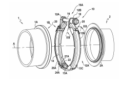
Description
[001] A presente descrição se refere a um sistema de aperto para conectar dois tubos cujas extremidades confrontantes têm superfícies de aperto salientes em relação à superfície externa cilíndrica dos ditos tubos, o sistema compreendendo um colar tendo uma tira capaz de cooperar com as ditas superfícies de aperto, o colar sendo capaz de ser apertado por uma redução no diâmetro da tira, a tira tendo um primeiro e um segundo flanco entre o qual um rebaixo interno capaz de receber as superfícies de aperto é delimitado.[001] The present description refers to a clamping system for connecting two tubes whose facing ends have clamping surfaces protruding from the cylindrical outer surface of said tubes, the system comprising a collar having a strip capable of cooperating with said surfaces of clamping, the collar being capable of being clamped by a reduction in the diameter of the strip, the strip having a first and a second flank between which an internal recess capable of receiving the clamping surfaces is delimited.
[002] Um sistema de aperto deste tipo é conhecido a partir da Patente Europeia N° EP 1 451 498. A seção transversal da tira do colar é, por exemplo, substancialmente em formato de V ou em formato de U, de modo que as aletas formadas por esta seção transversal se apoiem respectivamente na superfície de aperto do primeiro tubo e na do segundo tubo. Dessa forma, o aperto do colar tende a manter os tubos presos uns aos outros. A seção transversal em formato de V é interessante na medida em que, mediante aperto do colar, aproxima os tubos um do outro.[002] A clamping system of this type is known from European Patent No. EP 1 451 498. The cross section of the collar strip is, for example, substantially V-shaped or U-shaped, so that the fins formed by this cross section rest respectively on the clamping surface of the first tube and that of the second tube. In this way, tightening the collar tends to keep the tubes locked together. The V-shaped cross section is interesting in that, by tightening the collar, it brings the tubes closer together.
[003] Por exemplo, o colar é apertado usando um sistema de parafuso. Assim, as extremidades da tira podem ser levantadas de modo a formar linguetas de apoio providas de furos nos quais um parafuso pode ser inserido. A cabeça do parafuso é retida em relação a uma dessas linguetas, enquanto uma porca é retida em relação à outra lingueta, de modo que a rotação relativa entre o parafuso e a porca leva ao aperto do colar por uma diminuição no diâmetro da tira. No entanto, esta diminuição no diâmetro da tira pode ser conseguida de forma diferente, por exemplo, enganchando uma extremidade da tira na outra, particularmente usando um gancho levantado em relação à tira e uma lingueta também levantada em relação à tira, o gancho enganchando atrás da lingueta para manter o colar no estado apertado.[003] For example, the collar is tightened using a screw system. Thus, the ends of the strip can be lifted to form support tongues provided with holes in which a screw can be inserted. The head of the screw is retained relative to one of these tabs, while a nut is retained relative to the other tab, so that relative rotation between the screw and nut leads to tightening of the collar by a decrease in the diameter of the tab. However, this decrease in the diameter of the strip can be achieved differently, for example by hooking one end of the strip to the other, particularly using a hook raised with respect to the strip and a tongue also raised with respect to the strip, the hook hooking back of the tongue to keep the collar in tight condition.
[004] No documento EP 1 451 498, o sistema de aperto inclui ainda uma arruela que é fixada ao colar por meio de linguetas de aperto que a arruela inclui, esta arruela tendo também linguetas que são capazes de aderir ao primeiro tubo quando o colar é pré-montado na extremidade deste primeiro tubo. No sentido da presente descrição, “pré-montado” significa que o tubo é simplesmente encaixado no interior do colar, sem que este seja apertado. Assim, o fato de reter o colar no estado pré-montado em torno da extremidade do primeiro tubo permite colocá-lo em espera antes de encostar nos dois tubos e apertar a tira do colar em torno de suas extremidades montadas.[004] In EP 1 451 498, the clamping system further includes a washer that is fixed to the collar by means of clamping tabs that the washer includes, this washer also having tabs that are able to adhere to the first tube when the collar is pre-assembled at the end of this first tube. In the sense of the present description, "pre-assembled" means that the tube is simply fitted inside the collar, without the latter being tightened. Thus, retaining the collar in the pre-assembled state around the end of the first tube allows it to be put on hold before touching the two tubes and tightening the collar strip around their assembled ends.
[005] A Patente Europeia n° EP 2 598 785 propõe, por sua vez, equipar o sistema com primeiro e segundo meio de pré-montagem para pré-montar o colar no primeiro e segundo tubos, uma vez que tenham sido aproximados um do outro e encaixados no colar. Isso permite realizar o aperto do colar sem ter que segurar os dois tubos na posição. Nesta patente, o primeiro e o segundo meio de pré-montagem podem ser formados em uma única arruela transportada pela tira do colar, particularmente por seu primeiro flanco, ou então por duas arruelas, ou seja, uma primeira arruela similar à do sistema da patente EP 1 451 498, transportada pelo primeiro flanco, e uma segunda arruela transportada pelo segundo flanco.[005] European Patent No. EP 2 598 785 proposes, in turn, to equip the system with first and second pre-assembly means to pre-assemble the collar on the first and second tubes, once one of the another and embedded in the collar. This allows you to tighten the collar without having to hold the two tubes in position. In this patent, the first and second means of pre-assembly can be formed in a single washer carried by the collar strip, particularly by its first flank, or by two washers, i.e., a first washer similar to the system of the patent EP 1 451 498 carried by the first flank, and a second washer carried by the second flank.
[006] A Patente Europeia n° EP 3 217 059 propõe um sistema de aperto que compreende um colar do tipo acima mencionado, uma arruela e grampos de pré-montagem. A arruela é retida em relação ao colar e é provida com linguetas que permitem a pré-montagem na superfície de aperto de um dos tubos. Os grampos de pré-montagem são grampos individuais, que são retidos em relação à tira ao serem pinçados em um de seus flancos e permitem a pré-montagem na superfície de aperto do outro tubo.[006] European Patent No. EP 3 217 059 proposes a clamping system comprising a collar of the aforementioned type, a washer and pre-assembly clips. The washer is retained in relation to the collar and is provided with tabs that allow pre-assembly on the clamping surface of one of the tubes. Pre-assembly clamps are individual clamps, which are held in relation to the strip by being clamped on one of its sides and allow for pre-assembly on the clamping surface of the other tube.
[007] Os dispositivos citados são geralmente satisfatórios, mas requerem a utilização de uma ou duas arruelas para realizar a pré-montagem em pelo menos um dos tubos. Essas arruelas tendo uma periferia interna similar à do colar, representam uma quantidade relativamente grande de material. Além disso, a sua geometria é relativamente complexa, de modo que podem ser mantidas corretamente em relação à tira do colar em toda a sua periferia e podem reter corretamente em relação ao colar as extremidades dos respectivos tubos com os quais cooperam. Além disso, em alguns casos, a arruela também deve desempenhar uma função diferente da pré-montagem, por exemplo, uma função de vedação. Em alguns casos, esta função só pode ser garantida se a arruela tiver uma espessura precisa, nem sempre compatível com a elasticidade que as linguetas de pré-montagem devem ter para desempenharem corretamente a sua função, entendendo-se que essas linguetas possuem em princípio a mesma espessura da arruela, uma vez que são feitas da mesma cinta.[007] The devices mentioned are generally satisfactory, but require the use of one or two washers to perform pre-assembly in at least one of the tubes. These washers, having an inner periphery similar to the collar, represent a relatively large amount of material. Furthermore, their geometry is relatively complex, so that they can be held correctly in relation to the collar strip along its entire periphery and can correctly retain in relation to the collar the ends of the respective tubes with which they cooperate. Furthermore, in some cases the washer must also perform a different function than the pre-assembly, for example a sealing function. In some cases, this function can only be guaranteed if the washer has a precise thickness, not always compatible with the elasticity that the pre-assembly tabs must have to correctly perform their function, it being understood that these tabs have in principle the same thickness as the washer since they are made of the same strap.
[008] A combinação de uma arruela e grampos individuais é interessante para realizar uma pré-montagem nas superfícies de aperto dos dois tubos, mas ainda requer o uso de uma arruela de formato complexo para a pré-montagem em um dos tubos, e também requer a montagem dos vários elementos de acordo com os diferentes processos.[008] The combination of a washer and individual clamps is interesting to perform a pre-assembly on the clamping surfaces of the two tubes, but it still requires the use of a complex-shaped washer for pre-assembly on one of the tubes, and also requires the assembly of the various elements according to different processes.
[009] A descrição se refere a um sistema de aperto para conectar dois tubos cujas extremidades confrontantes têm superfícies de aperto salientes em relação à superfície externa cilíndrica dos ditos tubos, o sistema compreendendo um colar tendo uma tira capaz de cooperar com as ditas superfícies de aperto, o colar sendo capaz de ser apertado por uma redução no diâmetro da tira, a tira tendo um primeiro e um segundo flanco entre o qual um rebaixo interno capaz de receber as superfícies de aperto é delimitado, o sistema compreendendo ao menos um grampo de retenção compreendendo:
- - um elemento transversal que se estende através do rebaixo interno,
- - uma primeira e uma segunda aleta que se estendem radialmente para fora em relação ao elemento transversal cobrindo respectivamente o primeiro e o segundo flanco, e
- - uma primeira e uma segunda configuração de retenção cada uma compreendendo ao menos uma lingueta de retenção que se estende radialmente para dentro em relação ao elemento transversal,
- - a transverse element that extends through the internal recess,
- - a first and a second fin extending radially outwardly with respect to the transverse member covering the first and second flank respectively, and
- - a first and a second retaining configuration each comprising at least one retaining tab extending radially inwardly with respect to the transverse member,
[0010] Aqui, a indicação de que o elemento transversal pode ser removido mediante o aperto do colar significa que, mediante o aperto do colar, a configuração do elemento transversal muda de modo que o elemento transversal não forma um obstáculo a tal aperto. Em particular, o elemento transversal pode se deformar e/ou quebrar.[0010] Here, the indication that the transverse element can be removed by tightening the collar means that, upon tightening the collar, the configuration of the transverse element changes so that the transverse element does not form an obstacle to such tightening. In particular, the cross member may deform and/or break.
[0011] Opcionalmente, o elemento transversal se estende entre a primeira e a segunda aleta sendo opcionalmente fixado às bordas internas das aletas.[0011] Optionally, the transverse element extends between the first and second fins being optionally fixed to the inner edges of the fins.
[0012] Opcionalmente, as linguetas de retenção são fixadas às bordas internas das aletas.[0012] Optionally, the retaining tabs are attached to the inner edges of the fins.
[0013] Opcionalmente, a tira tem uma porção de crista anular que se estende entre o primeiro e o segundo flancos e o grampo de retenção tem linguetas de crista cobrindo pelo menos parcialmente a porção de crista anular.[0013] Optionally, the strap has an annular crest portion extending between the first and second flanks and the retaining clip has crest tongues at least partially covering the annular crest portion.
[0014] Opcionalmente, a porção de crista anular tem uma configuração de cunha com a qual as linguetas de crista cooperam, a configuração de cunha opcionalmente compreendendo um orifício ou uma cuba na qual as linguetas de crista penetram.[0014] Optionally, the annular crest portion has a wedge configuration with which the crest tongues cooperate, the wedge configuration optionally comprising a hole or a well into which the crest tongues penetrate.
[0015] Opcionalmente, no estado não apertado do colar, a primeira e a segunda aleta cobrem respectivamente o primeiro e o segundo flanco com uma folga.[0015] Optionally, in the loose state of the collar, the first and second wing respectively cover the first and second flank with a gap.
[0016] Opcionalmente, a primeira e a segunda aleta são configuradas para se afastar uma da outra para facilitar a deformação do elemento transversal para penetrar no rebaixo interno.[0016] Optionally, the first and second fins are configured to move away from each other to facilitate deformation of the cross member to penetrate the internal recess.
[0017] Opcionalmente, a primeira e a segunda aletas são configuradas para serem separadas em suas extremidades radiais externas.[0017] Optionally, the first and second fins are configured to be separated at their outer radial ends.
[0018] Opcionalmente, as aletas são configuradas para poderem ser retidas de forma removível contra um espaçamento de suas extremidades radiais externas.[0018] Optionally, the fins are configured to be releasably held against a spacing of their outer radial ends.
[0019] Opcionalmente, o elemento transversal tem pelo menos uma borda dobrada para dentro com uma fenda.[0019] Optionally, the cross member has at least one edge bent inward with a slit.
[0020] Opcionalmente, a fenda compreende um entalhe delimitado entre duas porções de aro, uma das porções de aro tendo opcionalmente uma porção em formato de aba estendida para dentro.[0020] Optionally, the slit comprises a notch delimited between two rim portions, one of the rim portions optionally having a flap-shaped portion extending inwardly.
[0021] Opcionalmente, o sistema de aperto compreende adicionalmente uma vedação anular disposta dentro da tira e cooperando com o grampo de retenção.[0021] Optionally, the clamping system further comprises an annular seal disposed within the strip and cooperating with the retaining clip.
[0022] Opcionalmente, o grampo de retenção é formado em uma peça, opcionalmente uma parte metálica recortada e dobrada de uma placa, por exemplo, uma cinta.[0022] Optionally, the retaining clip is formed in one piece, optionally a metal part cut and bent from a plate, eg a strap.
[0023] Opcionalmente, pelo menos uma das primeira e segunda configurações de cunha compreende duas linguetas de retenção localizadas em cada lado do elemento transversal.[0023] Optionally, at least one of the first and second wedge configurations comprises two retaining tongues located on each side of the cross member.
[0024] Opcionalmente, o sistema compreende uma pluralidade de grampos de retenção similares, distribuídos angularmente.[0024] Optionally, the system comprises a plurality of similar retaining clips, angularly distributed.
[0025] Opcionalmente, o elemento transversal é configurado para ser deformado para penetrar no rebaixo interno.[0025] Optionally, the cross member is configured to be deformed to penetrate the internal recess.
[0026] O grampo de retenção permite, portanto, realizar, em um único elemento de configuração simples, uma pré-montagem em relação às superfícies de aperto dos dois tubos. É possível posicionar o grampo de retenção no local desejado da circunferência da tira. Vários grampos de retenção, distribuídos angularmente, podem ser usados. O ou cada grampo de retenção sozinho realiza a pré-montagem em relação aos dois tubos. As áreas de engate entre o grampo e as superfícies de aperto são definidas pela geometria do grampo, o que permite otimizar a distribuição das forças de retenção da pré-montagem. Por exemplo, essas áreas de engate são alinhadas axialmente.[0026] The retaining clip therefore makes it possible to carry out, in a single element of simple configuration, a pre-assembly in relation to the clamping surfaces of the two tubes. You can position the retaining clip at the desired location on the circumference of the strap. Various retaining clips, distributed angularly, can be used. The or each retaining clip alone performs pre-assembly in relation to the two tubes. The areas of engagement between the clamp and the clamping surfaces are defined by the geometry of the clamp, which allows to optimize the distribution of the pre-assembly holding forces. For example, these engagement areas are axially aligned.
[0027] Quando o sistema de aperto compreende adicionalmente uma vedação, há grande liberdade quanto ao material desta vedação e sua geometria, uma vez que pode ser descorrelacionada da parte do sistema que realiza a pré-montagem, ou seja, neste caso o(s) grampo(s) de pré-montagem. A vedação pode, em particular, ser uma vedação multicamada ou de compósito (por exemplo, à base de mica) e/ou ser feita de metal do tipo aço inoxidável tendo recebido um tratamento de superfície.[0027] When the tightening system additionally comprises a seal, there is great freedom as to the material of this seal and its geometry, since it can be uncorrelated from the part of the system that performs the pre-assembly, that is, in this case the ) pre-assembly clamp(s). The seal may, in particular, be a multi-layer or composite seal (e.g. mica based) and/or be made of stainless steel type metal having received a surface treatment.
[0028] A presente descrição será bem compreendida e suas vantagens se tornarão mais evidentes mediante a leitura da seguinte descrição detalhada de uma modalidade representada a título de exemplo não limitativo.[0028] The present description will be well understood and its advantages will become more evident upon reading the following detailed description of an embodiment represented by way of non-limiting example.
[0029] [Fig. 1] Figura 1 é uma vista em perspectiva mostrando o sistema de aperto e as extremidades dos dois tubos antes da montagem deste sistema nessas extremidades.[0029] [Fig. 1] Figure 1 is a perspective view showing the clamping system and the ends of the two tubes before mounting this system on these ends.
[0030] [Fig. 2] Figura 2 mostra em perspectiva um grampo de retenção do sistema de aperto.[0030] [Fig. 2] Figure 2 shows in perspective a clamping system retaining clip.
[0031] [Fig. 3] Figura 3 é uma vista em corte no plano III da Figura 1, enquanto as extremidades dos dois tubos são pré-montadas com o sistema de aperto.[0031] [Fig. 3] Figure 3 is a sectional view on plane III of Figure 1, while the ends of the two tubes are pre-assembled with the clamping system.
[0032] [Fig. 4] Figura 4 é uma vista em corte em um plano perpendicular ao eixo geométrico A do colar.[0032] [Fig. 4] Figure 4 is a sectional view in a plane perpendicular to the geometric axis A of the collar.
[0033] [Fig. 4A] Figura 4A é uma ampliação de parte da Figura 4.[0033] [Fig. 4A] Figure 4A is an enlargement of part of Figure 4.
[0034] [Fig. 5] Figura 5 é uma vista similar à Figura 3 para uma variante.[0034] [Fig. 5] Figure 5 is a view similar to Figure 3 for a variant.
[0035] [Fig. 6] Figura 6 é uma vista em perspectiva do grampo de retenção usado nesta variante.[0035] [Fig. 6] Figure 6 is a perspective view of the retaining clip used in this variant.
[0036] [Fig. 7] Figura 7 é uma vista em perspectiva parcial mostrando a cooperação entre esse grampo de retenção e uma vedação.[0036] [Fig. 7] Figure 7 is a partial perspective view showing the cooperation between this retaining clip and a seal.
[0037] [Fig. 8] Figura 8 é uma vista similar às Figuras 3 e 5 para outra variante.[0037] [Fig. 8] Figure 8 is a view similar to Figures 3 and 5 for another variant.
[0038] [Fig. 9] Figura 9 é uma vista em perspectiva do grampo de retenção usado nesta variante adicional.[0038] [Fig. 9] Figure 9 is a perspective view of the retaining clip used in this additional variant.
[0039] [Fig. 10] Figura 10 é uma vista similar à Figura 1 ainda para outra variante.[0039] [Fig. 10] Figure 10 is a view similar to Figure 1 for yet another variant.
[0040] [Fig. 11] Figura 11 é uma vista similar às Figuras 3, 5 e 8 para esta outra variante.[0040] [Fig. 11] Figure 11 is a view similar to Figures 3, 5 and 8 for this other variant.
[0041] [Fig. 12] Figura 12 é uma vista em perspectiva de um grampo de retenção usado nesta outra variante.[0041] [Fig. 12] Figure 12 is a perspective view of a retaining clip used in this other variant.
[0042] [Fig. 13] Figura 13 é uma vista em perspectiva parcial mostrando a cooperação entre o grampo de retenção de acordo com esta outra variante e uma vedação.[0042] [Fig. 13] Figure 13 is a partial perspective view showing the cooperation between the retaining clip according to this other variant and a seal.
[0043] [Fig. 14] Figura 14 é uma vista similar às Figuras 3, 5, 8 e 11, mostrando, para a variante das Figuras 8 e 9, a situação no estado apertado do colar.[0043] [Fig. 14] Figure 14 is a view similar to Figures 3, 5, 8 and 11, showing, for the variant of Figures 8 and 9, the situation in the tight state of the collar.
[0044] O colar do sistema de aperto de acordo com a presente descrição é, por exemplo, geralmente similar ao descrito nos documentos EP 1 451 498, EP 2 598 785 e EP 3 217 059.[0044] The collar of the clamping system according to the present description is, for example, generally similar to that described in EP 1 451 498, EP 2 598 785 and EP 3 217 059.
[0045] Assim, como pode ser visto particularmente nas Figuras 1 a 3, este colar 10 inclui uma tira 12 que tem um primeiro flanco 13A e um segundo flanco 13B entre os quais um rebaixo interno 14 é delimitado.Thus, as can be seen particularly in Figures 1 to 3, this
[0046] A seguir, salvo indicação em contrário, os elementos que são direcionados para o eixo geométrico A do colar (isto é, o eixo geométrico A do anel formado pela tira do colar) serão referidos também como elementos “internos” assim como os elementos que estão mais próximos deste eixo geométrico A em relação a outros elementos, que, em contraste, serão referidos como elementos “externos”, os elementos “externos” também são aqueles que estão direcionados para longe do eixo geométrico A.[0046] Hereinafter, unless otherwise indicated, elements that are directed to the geometric axis A of the collar (i.e., the geometric axis A of the ring formed by the collar strip) will also be referred to as "internal" elements as well as the elements that are closer to this geometric axis A relative to other elements, which, in contrast, will be referred to as “external” elements, the “external” elements are also those that are directed away from the geometric axis A.
[0047] O sistema de aperto é usado para conectar dois tubos por suas extremidades. Assim, a Figura 1 mostra um primeiro tubo 1 e um segundo tubo 2, os quais têm, respectivamente, uma primeira superfície de aperto 1A e uma segunda superfície de aperto 2A projetando-se em relação às suas respectivas superfícies externas cilíndricas. Para a montagem dos tubos 1 e 2, o sistema de aperto pode ser disposto em torno das extremidades montadas dos tubos, de modo que as superfícies de aperto 1A e 2A estejam localizadas no rebaixo 14 da tira 12. Nesta situação, os flancos 13A e 13B cooperam respectivamente com as superfícies de aperto 1A e 2A, de modo que o aperto do colar mantém as duas extremidades.[0047] The clamping system is used to connect two tubes by their ends. Thus, Figure 1 shows a first tube 1 and a second tube 2, which respectively have a
[0048] A tira 12 tem, por exemplo, uma secção substancialmente em formato de U ou em formato V. Neste caso, a seção é do tipo misto combinando um formato de U e um de V, uma vez que a tira tem uma porção de crista anular relativamente larga 13C (a largura da tira sendo sua dimensão paralela ao eixo geométrico A) que de certa maneira forma a base de um U, enquanto seus flancos 13A e 13B são inclinados como os ramos de um V, por serem orientados em direção ao eixo geométrico A, embora tendo tendência a se afastar gradualmente um do outro conforme se movem em direção às suas respectivas bordas internas 13’A e 13’B. Além disso, os flancos 13A e 13B são, neste caso, ligeiramente curvados em suas bordas internas 13’A e 13’B até se tornarem substancialmente paralelos ao eixo geométrico A.[0048] The strip 12 has, for example, a substantially U-shaped or V-shaped section. In this case, the section is of the mixed type combining a U-shape and a V-shape, since the strip has a portion of relatively wide
[0049] Por sua vez, as superfícies de aperto 1A e 2A têm um diâmetro que aumenta gradualmente na direção das extremidades livres voltadas para os tubos, tendo, por exemplo, formato frusto-cônico. Assim, o aperto do colar nas superfícies de aperto das extremidades dos tubos a serem montadas tende a aproximar essas extremidades uma da outra. Neste caso, a extremidade livre do primeiro tubo 1 apresenta uma superfície de extremidade 1B que, a partir do topo da superfície de aperto 1A, é inclinada em relação a um plano radial de modo a aproximar-se gradualmente do eixo geométrico do tubo. Particularmente, esta superfície de extremidade 1B pode ter um formato frusto-cônico adaptado à periferia interna da superfície de aperto 2A do segundo tubo. Para a montagem, os eixos dos tubos 1 e 2 estão obviamente alinhados e coaxiais com o eixo geométrico A do colar.[0049] In turn, the clamping surfaces 1A and 2A have a diameter that gradually increases towards the free ends facing the tubes, having, for example, frusto-conical shape. Thus, the gripping of the collar on the gripping surfaces of the ends of the tubes to be assembled tends to bring these ends closer together. In this case, the free end of the first tube 1 has an end surface 1B which, starting from the top of the
[0050] Para apertar o colar 10, o diâmetro da tira 12 é reduzido. Neste caso, a tira 12 tem extremidades, respectivamente 12A e 12B, que são levantadas substancialmente radialmente de modo a formar linguetas de apoio. Estas linguetas são perfuradas de forma a permitir a passagem da haste 16A de um parafuso 16 através destas linguetas. De uma maneira conhecida per se, a cabeça do parafuso pode ser retida em relação à lingueta 12A, enquanto uma porca 18 coopera com a lingueta 12B, de modo que a rotação relativa do parafuso e da porca na direção do aparafusamento traz as linguetas de apoio 12A e 12B mais próximas uma da outra e, portanto, reduzem o diâmetro interno do anel formado pela tira enrolada, o que permite o aperto do colar. Também pode ser uma haste rosqueada cooperando com duas porcas.[0050] To tighten
[0051] O sistema de aperto inclui pelo menos um grampo de retenção 20 que serve para segurar este sistema pré-montado nas extremidades dos tubos 1 e 2. Neste caso, o sistema de aperto inclui uma pluralidade de grampos de retenção que é distribuída angularmente de acordo com a circunferência do colar. Neste caso, o sistema é composto por quatro grampos de retenção. Pode incluir menos ou mais do que isso.[0051] The clamping system includes at least one retaining
[0052] Pode ser visto nas Figuras 2 e 3 que o grampo de retenção 20 compreende um elemento transversal 22 que, quando o grampo está no lugar no colar, se estende através do rebaixo interno 14, no lado interno deste rebaixo. O grampo compreende adicionalmente uma primeira e uma segunda aleta, respectivamente 24A e 24B, que se estendem radialmente para fora em relação ao elemento transversal 22. Quando o grampo está no lugar na tira, as aletas 24A e 24B cobrem respectivamente o primeiro flanco 13A e o segundo flanco 13B.[0052] It can be seen in Figures 2 and 3 that the retaining
[0053] A indicação de que as aletas 24A e 24B se estendem radialmente para fora em relação ao elemento transversal significa que essas aletas se projetam radialmente para fora em relação ao elemento transversal. No entanto, como visto no desenho, eles podem não se estender estritamente em planos radiais. Neste caso, as aletas 24A e 24B são inclinadas de modo a se aproximarem uma da outra à medida que se afastam do eixo geométrico A do sistema de aperto. Cada aleta 24A ou 24B se estende no lado externo do respectivo flanco 13A ou 13B ao se sobrepor localmente a este flanco. Assim, consideradas em conjunto como visto na Figura 3, as aletas delimitam uma espécie de alojamento no qual uma porção da tira do colar está localizada.[0053] The indication that the
[0054] O grampo de retenção também tem uma primeira e uma segunda configuração de retenção, respectivamente 26A e 26B. Como pode ser visto na Figura 3, a primeira e a segunda configurações de retenção 26A e 26B cooperam respectivamente com a superfície de aperto 1A do primeiro tubo e a superfície de aperto 2A do segundo tubo para manter o sistema no estado pré-montado nas extremidades dos tubos. Cada uma das configurações de retenção compreende ao menos uma lingueta de retenção que se estende radialmente para dentro em relação ao elemento transversal 22. Neste caso, cada uma das configurações de retenção 26A e 26B compreende duas linguetas de retenção, respectivamente 27A, 28A e 27B, 28B que, em relação ao elemento transversal 22, se projetam radialmente para dentro. Para cada aleta 24A ou 24B, a configuração de retenção 26A ou 26B compreende, neste caso, duas linguetas de retenção, respectivamente 27A, 28A e 27B, 28B, que se estendem em cada lado do elemento transversal 22.[0054] The retaining clip also has a first and second retaining configuration, respectively 26A and 26B. As can be seen in Figure 3, the first and second retaining configurations 26A and 26B respectively cooperate with the
[0055] As linguetas de retenção são neste caso inclinadas de modo a se aproximarem de um plano radial mediano P do colar perpendicular ao eixo geométrico A, conforme se aproximam do eixo geométrico A. As extremidades livres das linguetas de retenção são, portanto, direcionadas para este plano radial e em direção a este eixo geométrico A. Em outras palavras, uma lingueta de retenção localizada na lateral de uma aleta, por exemplo, a lingueta de retenção 27A localizada no lado da aleta 24A se aproxima, em direção a sua extremidade livre, de uma lingueta de retenção localizada na lateral da outra aleta, por exemplo, a lingueta de retenção 27B localizada no lado da aleta 24B.[0055] The retaining tabs are in this case angled so as to approach a radial median plane P of the collar perpendicular to the geometric axis A, as they approach the geometric axis A. The free ends of the retaining tabs are therefore directed to this radial plane and towards this geometric axis A. In other words, a detent tab located on the side of a fin, for example, the
[0056] O elemento transversal 22 estende-se entre as aletas 24A e 24B sendo fixado às suas bordas internas, respectivamente 24’A e 24’B. Os entalhes 25 são delimitados entre o elemento transversal e cada lingueta de retenção, o que permite dissociar as deformações e os movimentos das linguetas de retenção e do elemento transversal 22. Neste caso, as linguetas de retenção 27A, 28A, 27B, 28B também estão fixadas às bordas internas 24’A, 24’B das aletas.[0056] The
[0057] Como pode ser visto na Figura 3, no estado não apertado do colar, o grampo de retenção sendo montado na tira, o elemento transversal 22 se estende através do rebaixo interno 14, isto é, forma de alguma maneira um formato de ponte interna para este rebaixo. Na etapa pré-montada, os topos das superfícies de aperto 1A e 2A dos tubos 1 e 2 estão localizados no lado interno do elemento transversal 22, possivelmente por estar em contato com o elemento transversal, como mostrado na Figura 3. Mediante o aperto do colar, o diâmetro da tira é reduzido e os flancos 13A e 13B são posicionados respectivamente contra as superfícies de aperto 1A e 2A. Isso significa que essas superfícies de aperto penetram no rebaixo 14. Para permitir isso, o elemento transversal 22 é removido, por exemplo, deformando-se até pressionar contra a parede interna do rebaixo, como será descrito em mais detalhes abaixo com referência à Figura 14, ou quebrando.[0057] As can be seen in Figure 3, in the loosened state of the collar, the retaining clip being mounted on the strip, the
[0058] Como indicado acima, a tira 12 do colar tem uma porção de crista anular 13C que se estende entre o primeiro e o segundo flancos 13A e 13B. Esta porção de crista anular é a área em que os flancos 13A e 13B se encontram. Pode ser visto que o grampo de retenção se estende parcialmente radialmente para fora da porção de crista anular 13C. Neste caso, o grampo de retenção 20 tem linguetas de crista, respectivamente 30A, 30B que cobrem parcialmente a porção de crista anular 13C. Neste caso, as linguetas de crista 30A e 30B estendem as aletas 24A e 24B de suas extremidades radiais externas 24”A e 24”B. As linguetas de crista 30A e 30B são direcionadas uma para a outra. Neste caso, as linguetas de crista compreendem extremidades, respectivamente 30’A e 30’B, que são curvas em ganchos direcionados radialmente para fora e cooperam com uma configuração de cunha da tira. Neste caso, a configuração de cunha compreende um orifício 13’C da porção de crista anular no qual as extremidades em gancho das linguetas de crista penetram. As linguetas de crista e o orifício 13 ‘C servem assim para cunhar o grampo de retenção 20 em relação à tira 12 do colar. Outras configurações de cunha podem ser providas. Particularmente, as linguetas de crista podem ser curvadas em ganchos sem se estenderem radialmente para dentro, e o orifício pode ser substituído por uma cuba deprimida radialmente para dentro na qual essas extremidades curvas penetrariam ou por outro relevo cooperando com as aletas ou as linguetas de crista. Esta conformação permite, no estado apertado do colar, evitar que as aletas 24A e 24B tenham tendência para se afastarem prematuramente uma da outra.[0058] As indicated above, the collar strip 12 has an
[0059] A cooperação entre as linguetas de crista e a configuração de cunha permite, assim, reter as aletas contra um espaçamento de suas extremidades radiais externas, mas as aletas podem ser afastadas, desde que o grampo de retenção não esteja no lugar ou quando esta cooperação cessa.[0059] The cooperation between the crest tongues and the wedge configuration thus allows retaining the fins against a spacing of their outer radial ends, but the fins can be moved apart as long as the retaining clip is not in place or when this cooperation ceases.
[0060] Quando o grampo de retenção está no lugar na tira do colar e a pré-montagem é realizada, entende-se que as superfícies de aperto 1A e 2A engatam radialmente dentro do elemento transversal 22 no final de um movimento axial relativo entre o colar e as respectivas superfícies de aperto. Durante este movimento axial, os topos radiais das superfícies de aperto 1A e 2A, respectivamente, cooperam com as linguetas de retenção 27A, 28A 27B, 28B, respectivamente, de modo que essas linguetas são removidas momentaneamente até que a superfície de aperto considerada tenha excedido a extremidade livre dessas linguetas na direção de aproximação ao plano radial médio P. Mediante esta remoção, um efeito de alavanca pode fazer com que as aletas 24A e 24B se afastem ligeiramente umas das outras, o que pode ser contrabalançado por sua elasticidade natural e/ou pela configuração de cunha conectando as linguetas de crista à tira, conforme descrito anteriormente, ou conectando as aletas juntas, como será descrito abaixo.[0060] When the retaining clip is in place on the collar strip and pre-assembly is carried out, it is understood that the clamping surfaces 1A and 2A radially engage within the
[0061] Uma vez que a superfície de aperto considerada 1A ou 2A atingiu o plano radial mediano P além da extremidade livre das linguetas de retenção consideradas, 27A, 28A ou 27B, 28B, essas linguetas de retenção podem naturalmente recuperar sua posição inicial de modo que suas respectivas extremidades livres se apoiem contra as respectivas superfícies de aperto 1A, 2A.[0061] Once the clamping surface considered 1A or 2A has reached the radial median plane P beyond the free end of the detent tabs considered, 27A, 28A or 27B, 28B, these detent tabs can naturally recover their initial position so that their respective free ends rest against the respective clamping surfaces 1A, 2A.
[0062] Além disso, neste caso, a configuração de cunha descrita acima também permite determinar a posição do grampo de retenção de acordo com a circunferência da tira.[0062] Furthermore, in this case, the wedge configuration described above also allows to determine the position of the retaining clip according to the circumference of the strip.
[0063] Pode ser visto na Figura 3 que, no estado não apertado do colar, a primeira e a segunda aleta 24A, 24B cobrem respectivamente o primeiro e o segundo flanco 13A, 13B com uma folga, um espaço E sendo delimitado entre a superfície interna da aleta considerada e a superfície externa do flanco considerado. Esta folga dá uma certa liberdade de deslocamento para as aletas e para as linguetas de retenção, facilitando a montagem do grampo de retenção na tira e a remoção das linguetas de retenção durante a pré-montagem conforme descrito.[0063] It can be seen in Figure 3 that, in the loose state of the collar, the first and
[0064] As aletas 24A e 24B não estão unidas em suas extremidades radiais externas. Em outras palavras, as aletas podem se mover separadas umas das outras em suas extremidades radiais externas, enquanto elas estão conectadas em suas extremidades radiais internas através do elemento transversal 22. Assim, o grampo de retenção é montado na tira através do interior desta. Para fazer isso, o usuário tem o grampo sob a tira, afasta as aletas 24A e 24B e insere a tira no espaço interno arranjado entre as aletas, até trazer de volta as aletas de modo a cobrir os flancos 13A e 13B. Nesse caso, o usuário também traz de volta as linguetas de crista para a posição representada na Figura 3 e faz com que cooperem.[0064]
[0065] Conforme indicado, as aletas 24A e 24B são desarticuladas em suas extremidades radiais externas 24”A, 24”B a partir das quais as linguetas de crista 30A, 30B se estendem. Particularmente na Figura 2, o elemento transversal 22 tem pelo menos uma borda dobrada para dentro com uma fenda. Neste caso, a Figura 2 mostra uma das bordas 22’ do elemento transversal 22, que é transversal ao eixo geométrico A. É visto que esta borda 22’ tem porções de aro dobradas para dentro, respectivamente 23A e 23B, entre as quais um entalhe 23C é arranjado. A borda oposta 22” do elemento transversal 22 é similar por simetria em relação a um plano perpendicular ao eixo geométrico A e passando pela linha central LM do elemento transversal 22, esta linha central passando pelo meio da largura do elemento transversal 22, sendo esta largura medida paralela ao eixo geométrico A. A fenda de cada uma das bordas 22’ e 22” compreende, portanto, um entalhe delimitado entre duas porções de aro dobradas para dentro. A porção de aro 23B tem uma porção em formato de aba 23’B que se estende ainda mais para dentro. Com referência às Figuras 3 e 4A, entende-se que no estado pré-montado do sistema de aperto nas extremidades dos tubos, os topos das superfícies de aperto 1A e 2A podem entrar em contato com as bordas livres das porções de aro 23A e 23B, e pode ajudar a prevenir a rotação dos tubos em relação ao sistema de aperto. Isso promove o aperto do sistema de aperto em relação ao tubo. As porções 23A e 23B podem dobrar para fora a fim de definir as dimensões diametrais suficientes para a inserção das superfícies de aperto dos tubos no sistema de aperto.[0065] As indicated,
[0066] No exemplo representado na Figura 3, o sistema de aperto não compreende uma arruela de vedação entre os tubos. Dessa forma, no estado pré-montado, uma lacuna é arranjada entre a superfície de extremidade 1B do tubo 1 e a face interna da superfície de aperto 2A do tubo 2. A porção em formato de aba 23C das bordas 22’ e/ou 22” do elemento transversal encaixa-se nesta lacuna, contribuindo assim para o posicionamento correto do sistema de aperto em relação aos tubos. Particularmente, a aba pode contribuir para a remontagem inicial em um dos tubos, calçando o sistema de aperto no lado oposto à superfície de aperto do tubo considerado. A aba atua como um encosto mediante a inserção do sistema de aperto na extremidade deste tubo.[0066] In the example shown in Figure 3, the clamping system does not comprise a sealing washer between the tubes. Thereby, in the pre-assembled state, a gap is arranged between the end surface 1B of the tube 1 and the inner face of the
[0067] Mediante o aperto, como indicado acima, o elemento transversal 22 é deformado para pressionar contra a parede interna do rebaixo 14 da tira e a aba 23C é removida para permitir que as extremidades dos tubos entrem em contato.[0067] Upon tightening, as indicated above, the
[0068] Para a pré-montagem, os vários grampos de retenção são colocados primeiro na tira. Em seguida, o sistema de aperto é trazido para a extremidade de um dos tubos, até que seja retido na superfície de aperto 1A ou 2A deste tubo pelas linguetas de retenção 27A, 28A ou 27B, 28B, em seguida, é trazido para a extremidade do outro tubo até que seja retido na superfície de aperto 2A ou 1A deste outro tubo pelas linguetas de retenção 27B, 28B ou 27A, 28A.[0068] For pre-assembly, the various retaining clips are placed on the strip first. Then, the clamping system is brought to the end of one of the tubes, until it is held on the
[0069] Com referência às Figuras 5 a 7, uma variante será agora descrita. Conforme visto na Figura 5, de acordo com esta variante, o sistema de aperto compreende uma arruela 40, particularmente uma arruela de vedação disposta entre as superfícies opostas dos tubos 1 e 2. Como se vê em particular na Figura 7, esta arruela tem, por exemplo, o formato de um anel frusto-cônico com deformações que podem ser comprimidas durante o aperto dos tubos para entrar em contato vedado com as superfícies opostas dos tubos. O grampo de retenção 20 é praticamente idêntico ao das figuras anteriores. Ele difere disso pela conformação das fendas das bordas dobradas 22’ e 22” do elemento transversal 22. De fato, como pode ser visto na Figura 6, a fenda da borda 22’ tem duas porções de aro 123A, 123B entre as quais um entalhe 123C está arranjado, mas as porções de aro não têm uma extensão em formato de aba ao contrário da porção de aro 23b descrita acima. As porções de aro 123A e 123B entram em contato com os topos das superfícies de aperto dos tubos como as porções de aro 23A e 23B mencionadas acima. O entalhe 123C recebe a borda anular externa 40’ da arruela de vedação 40 e, portanto, calça a última axialmente. Assim, vários grampos de retenção podem ser primeiro dispostos na tira do colar, então a arruela de vedação pode ser colocada no sistema de aperto de modo que seja mantida pelos entalhes 123C dos vários grampos de retenção, sendo assim “embutida” no colar. O sistema de aperto pode então ser pré-montado na extremidade de um dos tubos, enquanto é retido em sua superfície de aperto 1A ou 2A pelas linguetas de retenção 27 A, 28A ou as linguetas de retenção 27B, 28B, em seguida, trazidas para a extremidade do outro tubo, embora seja retido pré-montado em sua superfície de aperto 2A ou 1A pelas outras linguetas de retenção 27B, 28B ou 27A, 28A para atingir a situação representada na Figura 5.[0069] With reference to Figures 5 to 7, a variant will now be described. As seen in Figure 5, according to this variant, the clamping system comprises a
[0070] Com referência às Figuras 8 a 10, outra variante é descrita usando uma vedação de conformação diferente. Nesta outra variante, o grampo de retenção 20 é quase idêntico ao que foi descrito anteriormente. O sistema de aperto compreende uma vedação anular 140 que é, por exemplo, um cordão ou similar, feito de material elastomérico ou de um material mais duro, como mica. Pode ser visto na Figura 8 que esta vedação anular está disposta entre as superfícies opostas dos tubos 101 e 102 montados usando o dispositivo. Esses tubos são ligeiramente diferentes daqueles que foram descritos anteriormente. Eles têm as superfícies de aperto 101A e 102A similares às superfícies de aperto 1A e 2A descritas anteriormente, mas suas superfícies opostas delimitam um alojamento 101’A para receber a vedação 140. Neste caso, este alojamento 101’A é arranjado por um sulco anular na extremidade do tubo 101. Como pode ser visto na Figura 9, as fendas das bordas do elemento transversal 22 do grampo de retenção 20 são ligeiramente diferentes daquelas que foram descritas anteriormente. Neste caso, essas fendas compreendem, para cada borda, um entalhe 223C arranjado entre duas porções de aro 223A e 223B. A largura do entalhe 223C, medida entre as porções de aro 23A e 23B, é suficiente para acomodar a espessura da vedação 140. Pode ser visto na Figura 8 que a vedação 140 é calçada entre as porções de aro 223A e 223B. Esta vedação pode ser incorporada no sistema de aperto conforme descrito anteriormente com referência às Figuras 5 a 7.[0070] With reference to Figures 8 to 10, another variant is described using a different shaped seal. In this other variant, the retaining
[0071] Com referência às Figuras 10 a 13, outra variante será descrita agora. Nessas figuras, os elementos correspondentes aos das Figuras 1 a 7 são designados pelas mesmas referências aumentadas em 300.[0071] With reference to Figures 10 to 13, another variant will now be described. In these figures, elements corresponding to those in Figures 1 to 7 are designated by the same references enlarged by 300.
[0072] A Figura 10 mostra os dois tubos 301 e 302, com superfícies de aperto 301A e 302A similares às que foram descritas anteriormente. Além da superfície de aperto 301A, o tubo 301 é estendido por uma luva 301C, uma superfície 301B que se aproxima do eixo geométrico A enquanto se move em direção à extremidade livre do tubo sendo arranjada entre a superfície 301A e a luva 301C. A extremidade do tubo 202 tem uma porção alargada acomodando a luva 301C. Não precisa dizer que este é apenas um exemplo, os tubos podem ser similares aos que foram descritos com referência às figuras anteriores.[0072] Figure 10 shows the two
[0073] O sistema de aperto compreende um colar 310 que compreende uma tira 312 que, neste caso, compreende uma flange 312’ que se estende por uma das extremidades da tira para fazer a ponte do espaço interior localizado entre as linguetas de aperto 312A e 312B. Neste caso, a tira possui seção em V, como pode ser visto na Figura 11. Assim, a porção de crista anular 313C que se estende entre os flancos 313A e 313B tem uma pequena largura medida paralela ao eixo geométrico A.[0073] The clamping system comprises a
[0074] Os grampos de retenção 320 são ligeiramente diferentes dos grampos 20 descritos anteriormente. O grampo de retenção 320 compreende as aletas 324A, 324B e as conformações de retenção 326A e 326B compreendendo as linguetas de retenção 327A, 328A e 327B, 328B. O grampo de retenção 320 também tem um elemento transversal 322 similar ao elemento transversal 22 descrito anteriormente. As bordas do elemento transversal 322 têm fendas compreendendo um entalhe 323C disposto entre as porções de aro 323A e 323B.The retaining clips 320 are slightly different from the
[0075] Esta variante difere das anteriores, por um lado, pela conformação das configurações de cunha entre o grampo de retenção e a tira do colar. Neste caso, as extremidades radiais externas das aletas 324A e 324B são estendidas por linguetas de crista, respectivamente 330A e 330B. Estas linguetas estão deslocadas ao longo do comprimento do grampo de retenção 320, sendo este comprimento, neste caso, medido de acordo com a circunferência da tira do colar. As extremidades livres das linguetas de crista, respectivamente 330’A e 330’B, são dobradas para dentro para formar ganchos. Ao contrário das variantes anteriores, essas linguetas não engancham em uma configuração de cunha formada na tira, mas cada lingueta carregada por uma aleta engancha na outra aleta. Dessa forma, a aleta 324B compreende uma porção de engate 325B para a extremidade 330’A da lingueta de crista 330A e, da mesma forma, a aleta 324A compreende uma porção de engate 325A para a extremidade 330’B da lingueta de crista 330B. Isso permite reter as duas aletas 324A e 324B em relação uma à outra, enquanto evita que suas extremidades radiais externas, respectivamente 324” A e 324” B tenham uma tendência de se afastar uma da outra. Neste caso, as configurações de engate 325A e 325B são formadas por orifícios nas aletas. Pode haver conformações diferentes, por exemplo, cubas.[0075] This variant differs from the previous ones, on the one hand, by the conformation of the wedge configurations between the retaining clip and the collar strip. In this case, the outer radial ends of
[0076] Dessa forma, as aletas podem ser retidas contra um espaçamento de suas extremidades radiais externas, mas essa retenção é removível porque as linguetas de crista podem ser desengatadas para permitir esse espaçamento.[0076] In this way, the fins can be retained against a spacing of their outer radial ends, but this retention is removable because the crest tabs can be disengaged to allow this spacing.
[0077] Assim, para colocar o grampo de retenção na tira do colar, é garantido que as extremidades das linguetas de crista sejam desengatadas em relação às conformações de engate, de modo a espaçar as aletas e passar o grampo através do interior até a tira 312 ser alojado no espaço arranjado entre as aletas 324A e 324B. Essas aletas podem então ser fechadas enganchando as linguetas de crista nas configurações de engate.[0077] Thus, to place the retaining clip on the collar strip, it is ensured that the ends of the crest tongues are disengaged in relation to the engagement conformations, in order to space the fins and pass the clip through the interior to the
[0078] Além disso, esta variante difere das anteriores pelo fato de permitir o ajuste angular da vedação 340 em relação ao grampo de retenção. Na verdade, como pode ser visto na Figura 13, a borda 340’ desta vedação anular 340 tem um entalhe 340A no qual o elemento transversal 322 do grampo 320 está alojado. Claro, existem tantos entalhes 340A quanto grampos.[0078] In addition, this variant differs from previous ones in that it allows angular adjustment of the
[0079] As Figuras 3, 5, 8 e 11 mostram o sistema de aperto no estado pré-montado, no qual o elemento transversal do grampo de retenção faz uma ponte sobre o rebaixo da tira no lado interno. Neste estado pré-montado, os topos das superfícies de aperto dos tubos estão localizados contra a face interna deste elemento transversal, sem penetrar no rebaixo da tira. A Figura 14 mostra, para o exemplo da variante das Figuras 8 e 9, a situação enquanto o colar foi apertado nos tubos. Pode-se observar que, nesta situação, o elemento transversal de retenção 22 foi pressionado contra a face interna do rebaixo 14 da tira. Esta deformação causou o espaçamento das aletas 24A e 24B do grampo de retenção. As linguetas de crista 30A e 30B são, assim, desengatadas do orifício 13’C. Ao mesmo tempo, as linguetas de retenção foram pressionadas contra as superfícies de aperto 101A e 102A. Pela sua deformação, o elemento transversal é removido e permite o aperto. Outras maneiras do elemento transversal ser removido, por exemplo, uma ruptura, poderiam ser desenvolvidas.[0079] Figures 3, 5, 8 and 11 show the clamping system in the pre-assembled state, in which the transverse element of the retaining clip makes a bridge over the recess of the strip on the inner side. In this pre-assembled state, the tops of the clamping surfaces of the tubes are located against the inner face of this transverse element, without penetrating the undercut of the strip. Figure 14 shows, for the example of the variant of Figures 8 and 9, the situation while the collar was tightened onto the tubes. It can be seen that, in this situation, the transverse retaining
[0080] O grampo de retenção que foi descrito em relação às diferentes variantes pode ser formado em uma peça, nomeadamente na forma de uma parte metálica recortada e dobrada a partir de uma placa ou cinta metálica fina, por exemplo compreendida entre 0,2 e 0,6 mm.[0080] The retaining clip that has been described in relation to the different variants can be formed in one piece, namely in the form of a metal part cut and bent from a thin metal plate or band, for example between 0.2 and 0.6 mm.
[0081] O sistema de aperto pode ser entregue pré-montado, os grampos de retenção estando no lugar na tira do colar e, quando uma vedação é provida, esta vedação também estando no lugar por ser, por exemplo, retida nos entalhes das fendas que foram descritos.[0081] The clamping system can be delivered pre-assembled, the retaining clips being in place on the collar strip and, when a seal is provided, this seal also being in place by being, for example, retained in the slots of the slits that have been described.
Claims (17)
em que pelo menos um grampo de retenção (20; 320) compreende:
- - um elemento transversal (22; 322) que se estende através do rebaixo interno (14; 314),
- - uma primeira e uma segunda aleta (24A, 24B; 324A, 324B) que se estendem radialmente para fora em relação ao elemento transversal (22; 322) cobrindo respectivamente o primeiro e o segundo flanco (13A, 13B; 313A, 313B), e
- - uma primeira e uma segunda configuração de retenção (26A, 26B; 326A, 326B), cada uma compreendendo pelo menos uma lingueta de retenção (27A, 28A, 27B, 28B; 327A, 328A, 327B, 328B) que se estende radialmente para dentro em relação ao elemento transversal (22; 322),
wherein at least one retaining clip (20; 320) comprises:
- - a transverse element (22; 322) extending through the internal recess (14; 314),
- - a first and a second fin (24A, 24B; 324A, 324B) extending radially outwards relative to the transverse member (22; 322) covering the first and second flanks (13A, 13B; 313A, 313B), respectively, and
- - a first and a second retaining configuration (26A, 26B; 326A, 326B), each comprising at least one retaining tab (27A, 28A, 27B, 28B; 327A, 328A, 327B, 328B) which extends radially towards inside with respect to the transverse element (22; 322),
Applications Claiming Priority (2)
| Application Number | Priority Date | Filing Date | Title |
|---|---|---|---|
| FR1912959 | 2019-11-20 | ||
| FR1912959A FR3103233B1 (en) | 2019-11-20 | 2019-11-20 | Hose clamp |
Publications (1)
| Publication Number | Publication Date |
|---|---|
| BR102020021663A2 true BR102020021663A2 (en) | 2021-07-06 |
Family
ID=69468892
Family Applications (1)
| Application Number | Title | Priority Date | Filing Date |
|---|---|---|---|
| BR102020021663-5A BR102020021663A2 (en) | 2019-11-20 | 2020-10-22 | clamping system for connecting two tubes. |
Country Status (9)
| Country | Link |
|---|---|
| US (1) | US11549624B2 (en) |
| EP (1) | EP3825594B1 (en) |
| JP (1) | JP2021099157A (en) |
| KR (1) | KR20210061951A (en) |
| CN (1) | CN112824728A (en) |
| BR (1) | BR102020021663A2 (en) |
| ES (1) | ES2920499T3 (en) |
| FR (1) | FR3103233B1 (en) |
| MX (1) | MX2020012405A (en) |
Families Citing this family (8)
| Publication number | Priority date | Publication date | Assignee | Title |
|---|---|---|---|---|
| FR3108961B1 (en) * | 2020-04-03 | 2022-08-26 | Caillau | Clamping system for connecting pipes, including clamp and seal |
| ES2937419T3 (en) * | 2020-04-03 | 2023-03-28 | Caillau | Fitting system for connecting tubes, comprising a clamp and a washer carrying support lugs |
| DE102021102524A1 (en) * | 2021-02-03 | 2022-08-04 | Norma Germany Gmbh | Profile clamp, flange connection and turbocharger with it |
| FR3123406B1 (en) * | 2021-05-28 | 2023-06-02 | Caillau | Assembly assembly comprising two end pieces held fitted by a belt |
| GB2608686B (en) * | 2021-05-28 | 2024-02-14 | Caillau | Mounting assembly comprising two end pieces held fitted by a belt |
| DE102022105973A1 (en) * | 2022-03-15 | 2023-09-21 | Norma Germany Gmbh | profile clamp |
| FR3159823B1 (en) | 2024-03-01 | 2026-04-24 | Caillau | Clamping ear |
| CN118935115B (en) * | 2024-10-14 | 2025-01-07 | 兴化市方圆消防器材有限公司 | Fire hose joint |
Family Cites Families (9)
| Publication number | Priority date | Publication date | Assignee | Title |
|---|---|---|---|---|
| US3059947A (en) * | 1958-05-12 | 1962-10-23 | Aeroquip Corp | Ventilated band clamp |
| US4655481A (en) * | 1985-06-14 | 1987-04-07 | The Dow Chemical Company | Pipe aligning and joining |
| FR2833065B1 (en) | 2001-12-05 | 2004-09-03 | Caillau Ets | CLAMPING SYSTEM FOR THE SEALED CONNECTION OF TWO TUBES HAVING SUPPORT SURFACES |
| DE102004050300B4 (en) * | 2004-10-15 | 2009-02-12 | Norma Germany Gmbh | profile clip |
| FR2963404B1 (en) | 2010-07-27 | 2014-02-07 | Caillau Ets | CLAMPING SYSTEM FOR CONNECTING AND PRE-ASSEMBLING A FIRST AND A SECOND TUBE |
| DE102016103703A1 (en) * | 2016-03-02 | 2017-09-07 | Norma Germany Gmbh | profile clip |
| FR3048468B1 (en) | 2016-03-07 | 2018-04-06 | Etablissements Caillau | TIGHTENING SYSTEM COMPRISING A NECKLACE AND INDIVIDUAL PRE-ASSEMBLY CLIPS |
| FR3049997B1 (en) * | 2016-04-12 | 2018-05-04 | Etablissements Caillau | CLAMPING DEVICE COMPRISING A CLAMP AND A SLEEVE |
| ES2937419T3 (en) * | 2020-04-03 | 2023-03-28 | Caillau | Fitting system for connecting tubes, comprising a clamp and a washer carrying support lugs |
-
2019
- 2019-11-20 FR FR1912959A patent/FR3103233B1/en active Active
-
2020
- 2020-10-19 JP JP2020175286A patent/JP2021099157A/en active Pending
- 2020-10-22 BR BR102020021663-5A patent/BR102020021663A2/en not_active Application Discontinuation
- 2020-11-10 ES ES20206769T patent/ES2920499T3/en active Active
- 2020-11-10 US US17/093,732 patent/US11549624B2/en active Active
- 2020-11-10 EP EP20206769.0A patent/EP3825594B1/en active Active
- 2020-11-13 CN CN202011270891.4A patent/CN112824728A/en active Pending
- 2020-11-18 MX MX2020012405A patent/MX2020012405A/en unknown
- 2020-11-19 KR KR1020200155578A patent/KR20210061951A/en not_active Withdrawn
Also Published As
| Publication number | Publication date |
|---|---|
| US20210148498A1 (en) | 2021-05-20 |
| MX2020012405A (en) | 2021-05-21 |
| JP2021099157A (en) | 2021-07-01 |
| KR20210061951A (en) | 2021-05-28 |
| EP3825594A1 (en) | 2021-05-26 |
| FR3103233B1 (en) | 2021-11-26 |
| CN112824728A (en) | 2021-05-21 |
| FR3103233A1 (en) | 2021-05-21 |
| US11549624B2 (en) | 2023-01-10 |
| EP3825594B1 (en) | 2022-04-27 |
| ES2920499T3 (en) | 2022-08-04 |
Similar Documents
| Publication | Publication Date | Title |
|---|---|---|
| BR102020021663A2 (en) | clamping system for connecting two tubes. | |
| US9273706B2 (en) | Hinged clamping collar | |
| ES2704151T3 (en) | Expandable collar anchor system | |
| JP3217688U (en) | Hydraulic connector assembly, detent band for hydraulic connector and detent band for hydraulic connector assembly | |
| US3238619A (en) | Arch wire locking device for orthodontic bracket | |
| BR112014024486B1 (en) | fixing arrangement with automatic tolerance compensation, connection between component a and component b, as well as pre-assembly and assembly method | |
| BR112016009523B1 (en) | TIGHTENING CLAMP | |
| BR102017004288B1 (en) | Gripping system to connect two tubes together in a sealed manner | |
| ES2958947T3 (en) | Channel clamp with torque inducing element | |
| BR122019002740B1 (en) | ATTACHMENT ARRANGEMENT FOR ATTACHING A CONNECTOR TO AN ADMINISTRATION PORT OF A FLUID CONTAINER | |
| BR102017021143A2 (en) | SYSTEM FOR CONNECTING A FIRST PIPE AND A SECOND PIPE AND, TOGETHER TO CONNECT TWO PIPES | |
| KR102214785B1 (en) | Antirotation device for hydraulic connectors | |
| JP2000249274A (en) | Hose clip with positioning tool | |
| ES2562192T3 (en) | Pipe clamp | |
| PT1319147E (en) | Coupling for connecting a tubular fitting to a pipe | |
| CN109538611B (en) | Clamping and fixing assembly for insert nut or bolt buckle | |
| BR112013026152B1 (en) | method for connecting at least one pipe to a connection and connection | |
| BR102020008407A2 (en) | PRESSURE DEVICE, AND, PIPE PRESSURE SET | |
| BR102019008275A2 (en) | clamping system, assembly and mounting method | |
| US12385510B2 (en) | Tolerance compensation fastening assembly | |
| ES2274924T3 (en) | TUBE CLAMP. | |
| BR102020008387A2 (en) | SEALING, HOLDING DEVICE, AND, PIPE HOLDING SET | |
| BR112017027613B1 (en) | flexible tube clamp | |
| BR102020019103A2 (en) | TIGHTENING COLLAR | |
| CN116357654A (en) | Tolerance Compensation Fastening Components |
Legal Events
| Date | Code | Title | Description |
|---|---|---|---|
| B03A | Publication of a patent application or of a certificate of addition of invention [chapter 3.1 patent gazette] | ||
| B11A | Dismissal acc. art.33 of ipl - examination not requested within 36 months of filing | ||
| B11Y | Definitive dismissal - extension of time limit for request of examination expired [chapter 11.1.1 patent gazette] |