BR112012024974B1 - process for unwinding a mother roll to form multiple product rolls - Google Patents
process for unwinding a mother roll to form multiple product rolls Download PDFInfo
- Publication number
- BR112012024974B1 BR112012024974B1 BR112012024974-6A BR112012024974A BR112012024974B1 BR 112012024974 B1 BR112012024974 B1 BR 112012024974B1 BR 112012024974 A BR112012024974 A BR 112012024974A BR 112012024974 B1 BR112012024974 B1 BR 112012024974B1
- Authority
- BR
- Brazil
- Prior art keywords
- mandrel
- winding
- web
- core
- weft
- Prior art date
Links
- 238000000034 method Methods 0.000 title claims abstract description 63
- 230000008569 process Effects 0.000 title claims abstract description 54
- 238000004804 winding Methods 0.000 claims abstract description 277
- 239000000463 material Substances 0.000 claims description 16
- 230000003247 decreasing effect Effects 0.000 claims description 5
- 230000015572 biosynthetic process Effects 0.000 claims 1
- 239000011162 core material Substances 0.000 description 192
- 239000000047 product Substances 0.000 description 183
- 206010052428 Wound Diseases 0.000 description 60
- 208000027418 Wounds and injury Diseases 0.000 description 60
- 230000032258 transport Effects 0.000 description 56
- 238000000605 extraction Methods 0.000 description 22
- 239000000853 adhesive Substances 0.000 description 14
- 230000001070 adhesive effect Effects 0.000 description 14
- 239000003381 stabilizer Substances 0.000 description 14
- 230000008901 benefit Effects 0.000 description 12
- 230000008878 coupling Effects 0.000 description 12
- 238000010168 coupling process Methods 0.000 description 12
- 238000005859 coupling reaction Methods 0.000 description 12
- 238000012360 testing method Methods 0.000 description 10
- 239000012530 fluid Substances 0.000 description 9
- 239000000523 sample Substances 0.000 description 9
- 238000012546 transfer Methods 0.000 description 9
- 238000004519 manufacturing process Methods 0.000 description 8
- 238000011144 upstream manufacturing Methods 0.000 description 8
- 239000002699 waste material Substances 0.000 description 7
- 230000000087 stabilizing effect Effects 0.000 description 6
- 238000010276 construction Methods 0.000 description 5
- 238000012423 maintenance Methods 0.000 description 5
- 230000007246 mechanism Effects 0.000 description 4
- 238000004891 communication Methods 0.000 description 3
- 238000006073 displacement reaction Methods 0.000 description 3
- 238000010521 absorption reaction Methods 0.000 description 2
- 238000004590 computer program Methods 0.000 description 2
- 230000001143 conditioned effect Effects 0.000 description 2
- 230000000694 effects Effects 0.000 description 2
- 239000004744 fabric Substances 0.000 description 2
- 238000012986 modification Methods 0.000 description 2
- 230000004048 modification Effects 0.000 description 2
- 230000035515 penetration Effects 0.000 description 2
- -1 polyethylene Polymers 0.000 description 2
- 238000012545 processing Methods 0.000 description 2
- 230000008439 repair process Effects 0.000 description 2
- 101001096190 Homo sapiens Pleckstrin homology domain-containing family A member 1 Proteins 0.000 description 1
- 102100037862 Pleckstrin homology domain-containing family A member 1 Human genes 0.000 description 1
- 239000004698 Polyethylene Substances 0.000 description 1
- 239000004743 Polypropylene Substances 0.000 description 1
- CDBYLPFSWZWCQE-UHFFFAOYSA-L Sodium Carbonate Chemical compound [Na+].[Na+].[O-]C([O-])=O CDBYLPFSWZWCQE-UHFFFAOYSA-L 0.000 description 1
- 239000002390 adhesive tape Substances 0.000 description 1
- 238000005452 bending Methods 0.000 description 1
- 239000007795 chemical reaction product Substances 0.000 description 1
- 230000007423 decrease Effects 0.000 description 1
- 238000013461 design Methods 0.000 description 1
- 230000009977 dual effect Effects 0.000 description 1
- 239000012467 final product Substances 0.000 description 1
- 239000002783 friction material Substances 0.000 description 1
- 230000010354 integration Effects 0.000 description 1
- 239000000314 lubricant Substances 0.000 description 1
- 238000005259 measurement Methods 0.000 description 1
- 239000002184 metal Substances 0.000 description 1
- 229920000573 polyethylene Polymers 0.000 description 1
- 229920000098 polyolefin Polymers 0.000 description 1
- 229920001155 polypropylene Polymers 0.000 description 1
- 230000000284 resting effect Effects 0.000 description 1
- 239000007779 soft material Substances 0.000 description 1
- 239000007787 solid Substances 0.000 description 1
- 238000009864 tensile test Methods 0.000 description 1
- 239000004753 textile Substances 0.000 description 1
Images


Classifications
-
- B—PERFORMING OPERATIONS; TRANSPORTING
- B65—CONVEYING; PACKING; STORING; HANDLING THIN OR FILAMENTARY MATERIAL
- B65H—HANDLING THIN OR FILAMENTARY MATERIAL, e.g. SHEETS, WEBS, CABLES
- B65H18/00—Winding webs
- B65H18/08—Web-winding mechanisms
- B65H18/26—Mechanisms for controlling contact pressure on winding-web package, e.g. for regulating the quantity of air between web layers
-
- B—PERFORMING OPERATIONS; TRANSPORTING
- B65—CONVEYING; PACKING; STORING; HANDLING THIN OR FILAMENTARY MATERIAL
- B65H—HANDLING THIN OR FILAMENTARY MATERIAL, e.g. SHEETS, WEBS, CABLES
- B65H18/00—Winding webs
- B65H18/02—Supporting web roll
- B65H18/021—Multiple web roll supports
-
- B—PERFORMING OPERATIONS; TRANSPORTING
- B65—CONVEYING; PACKING; STORING; HANDLING THIN OR FILAMENTARY MATERIAL
- B65H—HANDLING THIN OR FILAMENTARY MATERIAL, e.g. SHEETS, WEBS, CABLES
- B65H18/00—Winding webs
- B65H18/08—Web-winding mechanisms
-
- B—PERFORMING OPERATIONS; TRANSPORTING
- B65—CONVEYING; PACKING; STORING; HANDLING THIN OR FILAMENTARY MATERIAL
- B65H—HANDLING THIN OR FILAMENTARY MATERIAL, e.g. SHEETS, WEBS, CABLES
- B65H19/00—Changing the web roll
- B65H19/22—Changing the web roll in winding mechanisms or in connection with winding operations
- B65H19/2207—Changing the web roll in winding mechanisms or in connection with winding operations the web roll being driven by a winding mechanism of the centre or core drive type
-
- B—PERFORMING OPERATIONS; TRANSPORTING
- B65—CONVEYING; PACKING; STORING; HANDLING THIN OR FILAMENTARY MATERIAL
- B65H—HANDLING THIN OR FILAMENTARY MATERIAL, e.g. SHEETS, WEBS, CABLES
- B65H19/00—Changing the web roll
- B65H19/22—Changing the web roll in winding mechanisms or in connection with winding operations
- B65H19/2276—The web roll being driven by a winding mechanism of the coreless type
-
- B—PERFORMING OPERATIONS; TRANSPORTING
- B65—CONVEYING; PACKING; STORING; HANDLING THIN OR FILAMENTARY MATERIAL
- B65H—HANDLING THIN OR FILAMENTARY MATERIAL, e.g. SHEETS, WEBS, CABLES
- B65H19/00—Changing the web roll
- B65H19/22—Changing the web roll in winding mechanisms or in connection with winding operations
- B65H19/26—Cutting-off the web running to the wound web roll
- B65H19/267—Cutting-off the web running to the wound web roll by tearing or bursting
-
- B—PERFORMING OPERATIONS; TRANSPORTING
- B65—CONVEYING; PACKING; STORING; HANDLING THIN OR FILAMENTARY MATERIAL
- B65H—HANDLING THIN OR FILAMENTARY MATERIAL, e.g. SHEETS, WEBS, CABLES
- B65H23/00—Registering, tensioning, smoothing or guiding webs
- B65H23/04—Registering, tensioning, smoothing or guiding webs longitudinally
- B65H23/18—Registering, tensioning, smoothing or guiding webs longitudinally by controlling or regulating the web-advancing mechanism, e.g. mechanism acting on the running web
- B65H23/195—Registering, tensioning, smoothing or guiding webs longitudinally by controlling or regulating the web-advancing mechanism, e.g. mechanism acting on the running web in winding mechanisms or in connection with winding operations
-
- B—PERFORMING OPERATIONS; TRANSPORTING
- B65—CONVEYING; PACKING; STORING; HANDLING THIN OR FILAMENTARY MATERIAL
- B65H—HANDLING THIN OR FILAMENTARY MATERIAL, e.g. SHEETS, WEBS, CABLES
- B65H2301/00—Handling processes for sheets or webs
- B65H2301/40—Type of handling process
- B65H2301/41—Winding, unwinding
- B65H2301/413—Supporting web roll
- B65H2301/4136—Mounting arrangements not otherwise provided for
- B65H2301/41362—Mounting arrangements not otherwise provided for one of the supports for the roller axis being movable as auxiliary bearing
-
- B—PERFORMING OPERATIONS; TRANSPORTING
- B65—CONVEYING; PACKING; STORING; HANDLING THIN OR FILAMENTARY MATERIAL
- B65H—HANDLING THIN OR FILAMENTARY MATERIAL, e.g. SHEETS, WEBS, CABLES
- B65H2301/00—Handling processes for sheets or webs
- B65H2301/40—Type of handling process
- B65H2301/41—Winding, unwinding
- B65H2301/413—Supporting web roll
- B65H2301/4139—Supporting means for several rolls
- B65H2301/41394—Supporting means for several rolls moving independently from each other
-
- B—PERFORMING OPERATIONS; TRANSPORTING
- B65—CONVEYING; PACKING; STORING; HANDLING THIN OR FILAMENTARY MATERIAL
- B65H—HANDLING THIN OR FILAMENTARY MATERIAL, e.g. SHEETS, WEBS, CABLES
- B65H2301/00—Handling processes for sheets or webs
- B65H2301/40—Type of handling process
- B65H2301/41—Winding, unwinding
- B65H2301/414—Winding
- B65H2301/4144—Finishing winding process
- B65H2301/41445—Finishing winding process after winding process
- B65H2301/41446—Finishing winding process after winding process removing roll/core from shaft/mandrel, e.g. by compressed air
-
- B—PERFORMING OPERATIONS; TRANSPORTING
- B65—CONVEYING; PACKING; STORING; HANDLING THIN OR FILAMENTARY MATERIAL
- B65H—HANDLING THIN OR FILAMENTARY MATERIAL, e.g. SHEETS, WEBS, CABLES
- B65H2301/00—Handling processes for sheets or webs
- B65H2301/40—Type of handling process
- B65H2301/41—Winding, unwinding
- B65H2301/414—Winding
- B65H2301/4146—Winding involving particular drive arrangement
- B65H2301/41466—Winding involving particular drive arrangement combinations of drives
- B65H2301/41468—Winding involving particular drive arrangement combinations of drives centre and nip drive
-
- B—PERFORMING OPERATIONS; TRANSPORTING
- B65—CONVEYING; PACKING; STORING; HANDLING THIN OR FILAMENTARY MATERIAL
- B65H—HANDLING THIN OR FILAMENTARY MATERIAL, e.g. SHEETS, WEBS, CABLES
- B65H2404/00—Parts for transporting or guiding the handled material
- B65H2404/20—Belts
-
- B—PERFORMING OPERATIONS; TRANSPORTING
- B65—CONVEYING; PACKING; STORING; HANDLING THIN OR FILAMENTARY MATERIAL
- B65H—HANDLING THIN OR FILAMENTARY MATERIAL, e.g. SHEETS, WEBS, CABLES
- B65H2404/00—Parts for transporting or guiding the handled material
- B65H2404/20—Belts
- B65H2404/26—Particular arrangement of belt, or belts
- B65H2404/262—Arrangements of belts facing rollers
-
- B—PERFORMING OPERATIONS; TRANSPORTING
- B65—CONVEYING; PACKING; STORING; HANDLING THIN OR FILAMENTARY MATERIAL
- B65H—HANDLING THIN OR FILAMENTARY MATERIAL, e.g. SHEETS, WEBS, CABLES
- B65H2515/00—Physical entities not provided for in groups B65H2511/00 or B65H2513/00
- B65H2515/12—Density
-
- B—PERFORMING OPERATIONS; TRANSPORTING
- B65—CONVEYING; PACKING; STORING; HANDLING THIN OR FILAMENTARY MATERIAL
- B65H—HANDLING THIN OR FILAMENTARY MATERIAL, e.g. SHEETS, WEBS, CABLES
- B65H2515/00—Physical entities not provided for in groups B65H2511/00 or B65H2513/00
- B65H2515/30—Forces; Stresses
- B65H2515/32—Torque e.g. braking torque
Landscapes
- Replacement Of Web Rolls (AREA)
Abstract
PROCESSO PARA DESENROLAR UM ROLO-MÃE PARA FORMAR MÚLTIPLOS ROLOS DE PRODUTO A presente invenção provê um bobinador para bobinamento de uma trama para produzir um produto enrolado. O bobinador inclui um aparelho de transporte de trama que é usado para transporte da trama. Em uma modalidade exemplar também está incluída uma plurali-dade de módulos de bobinamento independentes. Os módulos de bobinamento estão posicionados de maneira independente para se engatarem, de maneira independente, com a trama conforme a trama seja transportada pelo aparelho de transporte de trama. Os módulos de bobinamento podem ser configurados para enrolar a trama para formar um produto enrolado por bobinamento de centro, bobinamento de superfície e combinações de bobinamento de centro e de superfície. Os módulos de bobinamento são estrutural-mente e operacionalmente independentes uns dos outros, no sentido que, se um módulo for desabilitado, outro ainda pode operar para produzir o produto enrolado sem paralisar o bobinador.PROCESS FOR UNWINDING A MASTER ROLL TO FORM MULTIPLE PRODUCT ROLLS The present invention provides a winder for winding a web to produce a wound product. The winder includes a weft transport apparatus which is used to transport the weft. In an exemplary embodiment, a plurality of independent winding modules is also included. The winding modules are independently positioned to independently engage with the weft as the weft is transported by the weft transport apparatus. The winding modules can be configured to wind the web to form a wound product by center winding, surface winding, and center and surface winding combinations. The winding modules are structurally and operationally independent of each other, in the sense that if one module is disabled, another can still operate to produce the wound product without paralyzing the winder.
Description
[001] Bobinadores (winders) são máquinas que enrolam comprimentos de papel, comumente conhecidos como tramas de papel, em rolos. Essas máquinas são capazes de enrolar comprimentos de trama em rolos em altas velocidades através de um processo automatizado. Bobinadores de torre são bem conhecidos na técnica. Bobinadores de torre convencionais compreendem um conjunto de torre rotativo, que suporta uma pluralidade de mandris para rotação em torno de um eixo de torre. Os mandris transitam em uma trajetória circular em uma distância fixa a partir do eixo da torre. Os mandris se engatam a núcleos ocos sobre os quais um papel possa ser enrolado. Tipicamente, a trama de papel é desenrolada a partir de um rolo- mãe de uma maneira contínua, e o bobinador de torre enrola novamente a trama de papel por sobre os núcleos suportados nos mandris para fornecer toras (logs) individuais de diâmetros relativamente pequenos. A tora de produto enrolado é, então, cortada em comprimentos designados para formar o produto final. Os produtos finais tipicamente criados por essas máquinas e processos são rolos de papel tissue higiênico, rolos de toalhas de papel, rolos de papel e os similares.[001] Winders are machines that wind lengths of paper, commonly known as paper webs, into rolls. These machines are capable of winding web lengths into rolls at high speeds through an automated process. Tower winders are well known in the art. Conventional turret winders comprise a rotating turret assembly, which supports a plurality of mandrels for rotation about a turret axis. The chucks travel on a circular path at a fixed distance from the axis of the turret. The mandrels engage with hollow cores over which a paper can be rolled. Typically, the paper web is unwound from a mother roll in a continuous manner, and the tower winder rewinds the paper web over cores supported on the mandrels to provide individual logs of relatively small diameters. The rolled product log is then cut into designated lengths to form the final product. The end products typically created by these machines and processes are toilet tissue rolls, paper towel rolls, paper rolls and the like.
[002] A técnica de bobinamento usada em bobinadores de torre é conhecida como bobinamento de centro. Um aparelho de bobinamento de centro, por exemplo, conforme descrito na patente U.S. reconcedida Número 28.353 para Nystrand, a qual é aqui incorporada por referência. No bobinamento de centro, um mandril é girado a fim de enrolar uma trama para formar um rolo/tora, com ou sem um núcleo. Tipicamente, o núcleo é montado em um mandril que gira em altas velocidades no início de um ciclo de bobinamento e, então, desacelera conforme o tamanho do produto enrolado sendo bobinado aumente, a fim de manter uma velocidade de superfície constante, correspondendo aproximadamente com a velocidade da trama. Bobinadores de centro funcionam bem quando a trama que estiver sendo enrolada apresentar uma superfície impressa, texturizada ou escorregadia. Além disso, tipicamente, bobinadores de centro são preferíveis para produzir, de maneira eficiente, produtos enrolados com volumes mais elevados, bobinados macios.[002] The winding technique used in tower winders is known as center winding. A center winding apparatus, for example, as described in reissued U.S. Patent Number 28,353 to Nystrand, which is incorporated herein by reference. In center winding, a mandrel is rotated to wind a web to form a roll/log, with or without a core. Typically, the core is mounted on a mandrel that rotates at high speeds at the beginning of a winding cycle and then decelerates as the size of the wound product being wound increases, in order to maintain a constant surface speed, roughly corresponding with the plot speed. Center winders work well when the web being wound has a printed, textured, or slippery surface. In addition, typically center winders are preferred to efficiently produce higher volume, soft wound wound products.
[003] Um segundo tipo de bobinamento é conhecido na técnica como bobinamento de superfície. Uma máquina que usa a técnica de bobinamento de superfície é descrita na Patente U.S. No. 4.583.698. Tipicamente, no bobinamento de superfície, a trama é enrolada por sobre o núcleo via contato e atrito desenvolvidos com rolos rotativos. Um nip é tipicamente formado entre dois ou mais sistemas de rolos que atuam conjuntamente. No bobinamento de superfície, o núcleo e a trama que é enrolada em torno do núcleo são usualmente impelidos por rolos rotativos que operam aproximadamente na mesma velocidade que a velocidade da trama. O bobinamento de superfície é preferível para produzir, de maneira eficiente, produtos enrolados com volumes mais baixos, bobinados rígidos.[003] A second type of winding is known in the art as surface winding. A machine using the surface winding technique is described in U.S. Patent No. 4,583,698. Typically, in surface winding, the web is wound over the core via contact and friction developed with rotating rollers. A nip is typically formed between two or more roller systems that act together. In surface winding, the core and the web that is wound around the core are usually driven by rotating rollers that operate at approximately the same speed as the speed of the web. Surface winding is preferable to efficiently produce wound products with lower volumes, rigid wounds.
[004] Um problema encontrado em bobinadores tanto de centro quanto de superfície envolve a paralisação do bobinador quando ocorre uma condição, tal como a falha de carga de um núcleo ou uma falha por rompimento da trama. Se um núcleo em um bobinador de torre, por exemplo, não for carregado de maneira apropriada por sobre o mandril, a máquina tem que ser paralisada para que a falha seja corrigida. Similarmente, uma falha por rompimento da trama em um bobinador de superfície também resultará na paralisação da máquina. Isso resulta em uma perda de produção e na exigência imediata de se obter serviços de reparo. A presente invenção fornece uma maneira de se eliminar tais problemas, permitindo que a máquina continue a produzir produto enrolado, muito embora uma condição de falha tenha ocorrido. Adicionalmente, a invenção incorpora as vantagens do bobinamento tanto de centro quanto de superfície para produzir produtos enrolados apresentando várias características, por uso de bobinamento de centro, de bobinamento de superfície ou uma combinação de bobinamento de centro e de superfície.[004] A problem encountered in both center and surface winders involves the stoppage of the winder when a condition occurs, such as a core load failure or a web break failure. If a core in a tower winder, for example, is not properly loaded over the mandrel, the machine has to be stopped for the fault to be corrected. Similarly, a weft break failure on a surface winder will also result in machine downtime. This results in a loss of production and an immediate requirement for repair services. The present invention provides a way to eliminate such problems by allowing the machine to continue to produce rolled product even though a fault condition has occurred. Additionally, the invention incorporates the advantages of both center and surface winding to produce wound products having various characteristics, by use of center winding, surface winding or a combination of center and surface winding.
[005] Outro problema com bobinadores tanto de centro quanto de superfície convencionais é que os bobinadores propiciam controle limitado sobre as propriedades do produto enrolado resultante. Por exemplo, com respeito a bobinadores de centro, o único mecanismo de controle para controlar o volume de rolo do produto acabado é a tensão de trama. Portanto, bobinadores de centro somente podem produzir produtos apresentando uma gama limitada de volumes de rolo sem causar atraso excessivo ou aumentando a resistência do produto a níveis indesejados.[005] Another problem with both conventional center and surface winders is that the winders provide limited control over the properties of the resulting wound product. For example, with respect to center winders, the only control mechanism to control the roll volume of the finished product is the weft tension. Therefore, core winders can only produce products having a limited range of roll volumes without causing excessive delay or increasing product strength to unwanted levels.
[006] Bobinadores de superfície também são similarmente limitados na capacidade de controlar o volume de rolo de produtos resultantes. Bobinadores de superfície, por exemplo, dependem do atrito de superfície para impelir o rolo de bobinamento. Tentativas de produzir produtos com um volume de rolo relativamente elevado exigem que a pressão de contato entre o material sendo enrolado e o dispositivo de bobinamento de superfície seja diminuída. A pressão de contato decrescente, entretanto, também diminui o atrito e resulta em perda de controle sobre o produto sendo formado conduzindo a problemas de qualidade e a problemas de produtividade associados com instabilidade de tora no compartimento de bobinamento. Bobinadores de superfície também apresentam problemas quando se corre em velocidades relativamente mais elevadas, quando da produção de produtos com volumes de rolo mais elevados.[006] Surface winders are also similarly limited in their ability to control the roll volume of resulting products. Surface winders, for example, rely on surface friction to propel the winding roll. Attempts to produce products with a relatively high roll volume require that the contact pressure between the material being wound and the surface winding device be decreased. The decreasing contact pressure, however, also decreases friction and results in loss of control over the product being formed leading to quality problems and productivity problems associated with log instability in the winding compartment. Surface winders also have problems running at relatively higher speeds when producing products with higher roll volumes.
[007] Em vista do acima, existe atualmente uma demanda por um sistema e um processo que sejam capazes de produzir produtos enrolados apresentado uma maior gama de características de volume de rolo. Em adição, existe uma demanda por um sistema e um processo capazes de produzir produtos ou apresentando um baixo volume de rolo ou um elevado volume de rolo, embora também produzindo os produtos em velocidades relativamente elevadas e sem interrupção.[007] In view of the above, there is currently a demand for a system and a process that are capable of producing rolled products presenting a wider range of roll volume characteristics. In addition, there is a demand for a system and process capable of producing products either having a low roll volume or a high roll volume, while also producing the products at relatively high speeds and without interruption.
[008] Na técnica anterior, um bobinador é tipicamente conhecido como um aparelho que realiza de fato o primeiro bobinar daquela trama, de maneira geral formando o que é conhecido como um rolo-mãe (parent roll). Um rebobinador, por outro lado, é um aparelho que enrola a trama a partir do rolo-mãe por sobre um rolo que seja essencialmente o produto acabado. Deve ser observado que a técnica anterior não é consistente em designar o que é e o que não é um bobinador ou um rebobinador. Por exemplo, rebobinadores são, algumas vezes, chamados de bobinadores, e, algumas vezes, refere-se aos bobinadores como rebobinadores.[008] In the prior art, a winder is typically known as an apparatus that actually performs the first winding of that web, generally forming what is known as a parent roll. A rewinder, on the other hand, is an apparatus that winds the web from the mother roll onto a roll that is essentially the finished product. It should be noted that the prior art is not consistent in designating what is and is not a winder or a winder. For example, winders are sometimes called winders, and winders are sometimes referred to as winders.
[009] Objetos e vantagens da invenção serão mostrados em parte na descrição seguinte, ou podem ser óbvios a partir da descrição, ou podem ser aprendidos a partir da prática da presente invenção.[009] Objects and advantages of the invention will be shown in part in the following description, or they may be obvious from the description, or they may be learned from the practice of the present invention.
[0010] Conforme usado aqui, "bobinador" é genérico em relação a uma máquina para formação de um rolo-mãe, e uma máquina (rebobinador) para formação de um rolo/tora a partir de um rolo-mãe. Em outras palavras, a palavra "bobinador" é ampla o bastante para cobrir um "bobinador" e um "rebobinador".[0010] As used herein, "winder" is generic in relation to a machine for forming a mother roll, and a machine (rewinder) for forming a roll/log from a mother roll. In other words, the word "rewinder" is wide enough to cover a "rewinder" and a "rewinder".
[0011] A presente invenção também inclui um aparelho de transporte de trama para transportar uma trama até um bobinador para bobinamento da trama para produzir um produto enrolado. Além disso, uma pluralidade de módulos de bobinamento independentes pode estar presente. Os módulos de bobinamento são posicionados, de maneira independente, para se engatarem, de maneira independente, à trama, conforme ela seja transportada pelo aparelho de transporte de trama. Os módulos de bobinamento se engatam à trama e enrolam a trama para formar um produto enrolado. Os módulos de bobinamento são configurados para enrolar usando bobinamento de centro, bobinamento de superfície ou uma combinação de bobinamento de centro e de superfície. Os módulos de bobinamento são controlados e posicionados independentemente um do outro. Portanto, se um módulo de bobinamento for desabilitado, outro módulo de bobinamento ainda poderá operar para produzir o produto enrolado sem se ter que paralisar o bobinador.[0011] The present invention also includes a web transport apparatus for transporting a web to a winder for winding the web to produce a wound product. Furthermore, a plurality of independent winding modules can be present. The winding modules are independently positioned to independently engage the weft as it is transported by the weft transport apparatus. Winding modules engage the web and wind the web to form a wound product. Winding modules are configured to wind using center winding, surface winding or a combination of center and surface winding. The winding modules are controlled and positioned independently of each other. Therefore, if one winding module is disabled, another winding module can still operate to produce the wound product without having to stop the winder.
[0012] Também de acordo com a presente invenção, um bobinador é descrito conforme acima, em que a pluralidade de módulos de bobinamento independentes pode, cada um, apresentar um aparelho de carregamento de núcleo e um aparelho de extração (stripping) de produto.[0012] Also according to the present invention, a winder is described as above, wherein the plurality of independent winding modules can each have a core loading apparatus and a product stripping apparatus.
[0013] De acordo com a presente invenção, também é descrito um bobinador conforme apresentado acima, em que a pluralidade de módulos de bobinamento independentes, cada um, apresenta um mandril impelido de centro por sobre o qual a trama é enrolada para formar o produto enrolado.[0013] In accordance with the present invention, a winder as shown above is also described, wherein the plurality of independent winding modules each have a center driven mandrel over which the web is wound to form the product rolled.
[0014] De acordo com a presente invenção, também é descrito um método de produção de um produto enrolado a partir de uma trama. Esse método inclui a etapa de transporte da trama por um aparelho de transporte de trama. Outra etapa no método da presente invenção pode envolver o bobinamento da trama para formar o produto enrolado por uso de um ou mais módulos de bobinamento. Isso pode envolver o bobinamento da trama por um ou mais módulos de bobinamento da pluralidade de módulos de bobinamento em qualquer dado instante. O processo que é usado para enrolar a trama pode ser bobinamento de centro, bobinamento de superfície ou uma combinação de bobinamento tanto de centro quanto de superfície. Os módulos de bobinamento podem atuar de maneira independente um do outro para permitir que um ou mais módulos de bobinamento ainda enrolem a trama para produzir um produto enrolado sem se ter que paralisar a pluralidade de módulos de bobinamento, se qualquer um dos módulos de bobinamento restantes falhar ou forem desabilitados. O método de acordo com a presente invenção também inclui a etapa de transporte do produto enrolado a partir do módulo de bobinamento.[0014] According to the present invention, a method of producing a rolled product from a web is also described. This method includes the step of transporting the web by a web transporting apparatus. Another step in the method of the present invention may involve winding the web to form the wound product using one or more winding modules. This may involve the weft winding by one or more winding modules of the plurality of winding modules at any given time. The process that is used to wind the weft can be center winding, surface winding or a combination of both center and surface winding. The winding modules can act independently of each other to allow one or more winding modules to still wind the web to produce a wound product without having to shut down the plurality of winding modules, if any of the remaining winding modules fail or are disabled. The method according to the present invention also includes the step of transporting the rolled product from the winding module.
[0015] Outra modalidade exemplificativa da presente invenção pode incluir um bobinador, que é usado para bobinamento de uma trama, para produzir um produto enrolado, que apresente um aparelho de transporte de trama para transportar uma trama. Essa modalidade exemplificativa também apresenta uma pluralidade de módulos de bobinamento independentes montados dentro uma armação, em que cada módulo de bobinamento apresenta um aparelho de posicionamento para mover o módulo de bobinamento para engate com a trama. Cada módulo de bobinamento também apresenta um mandril que seja girado, sobre o qual a trama é enrolada para formar o produto enrolado. Os módulos de bobinamento são operacionalmente independentes uns dos outros, em que se qualquer dos módulos de bobinamento for desabilitado, os módulos de bobinamento restantes poderiam continuar a operar para produzir o produto enrolado sem se ter que paralisar o bobinador. A velocidade de rotação do mandril e a distância entre o mandril e o aparelho de transporte de trama podem ser controladas, de modo a produzir um produto enrolado com as características desejadas. Os módulos de bobinamento são configurados para enrolar a trama por bobinamento de centro, bobinamento de superfície e combinações de bobinamento de centro e de superfície.[0015] Another exemplary embodiment of the present invention may include a winder, which is used for winding a weft, to produce a wound product having a weft transport apparatus for transporting a weft. This exemplary embodiment also features a plurality of independent winding modules mounted within a frame, each winding module having positioning apparatus for moving the winding module into engagement with the web. Each winding module also features a mandrel that is rotated, over which the web is wound to form the wound product. The winding modules are operationally independent of each other, in that if any of the winding modules were disabled, the remaining winding modules could continue to operate to produce the wound product without having to shut down the winder. The rotation speed of the mandrel and the distance between the mandrel and the web transport apparatus can be controlled so as to produce a rolled product with the desired characteristics. The winding modules are configured to wind the web by center winding, surface winding and combinations of center and surface winding.
[0016] Outro aspecto da presente invenção inclui uma modalidade exemplificativa do bobinador conforme imediatamente discutido, em que cada módulo de bobinamento pode apresentar um aparelho de carregamento de núcleo para carregamento de um núcleo por sobre o mandril. Essa modalidade exemplificativa também apresenta um aparelho de extração de produto enrolado para remoção do produto enrolado do módulo de bobinamento.[0016] Another aspect of the present invention includes an exemplary embodiment of the winder as immediately discussed, wherein each winding module may have a core loading apparatus for loading a core onto the mandrel. This exemplary embodiment also features a rolled product extraction apparatus for removing the rolled product from the winding module.
[0017] Por exemplo, em uma modalidade, o aparelho de carregamento de núcleo pode compreender um conjunto de carregamento de núcleo montado de maneira deslizante sobre um mandril. O conjunto de carregamento de núcleo pode incluir um dispositivo de agarramento e um estabilizador. O dispositivo de agarramento pode incluir pelo menos dois membros de agarramento, que sejam móveis em direção e estejam afastados um do outro. Por exemplo, os membros de agarramento podem ser atuados pneumaticamente ou hidraulicamente. O estabilizador, por outro lado, pode ser engatado de maneira deslizante no mandril, para estabilização do mandril conforme o dispositivo de agarramento puxa um núcleo por sobre o mandril. O estabilizador, por exemplo, pode apresentar uma configuração similar ao dispositivo de agarramento. O estabilizador pode incluir pelo menos dois membros de estabilização, que sejam móveis em direção e estejam afastados uns dos outros e que circundem o mandril. De maneira similar ao dispositivo de agarramento, os membros de estabilização podem ser atuados pneumaticamente ou hidraulicamente.[0017] For example, in one embodiment, the core loading apparatus may comprise a core loading assembly slidably mounted on a mandrel. The core loading assembly may include a grip device and a stabilizer. The gripping device may include at least two gripping members, which are movable towards and are spaced apart from each other. For example, the gripping members can be pneumatically or hydraulically actuated. The stabilizer, on the other hand, can be slidably engaged with the mandrel to stabilize the mandrel as the gripping device pulls a core over the mandrel. The stabilizer, for example, can have a similar configuration to the gripping device. The stabilizer may include at least two stabilizing members, which are movable towards and apart from each other and which surround the mandrel. Similar to the gripping device, the stabilizing members can be pneumatically or hydraulically actuated.
[0018] O conjunto de carregamento de núcleo pode ser fixado a um atuador, que seja configurado para mover o conjunto de carregamento de núcleo para trás e para frente através do mandril. Nessa modalidade, a fim de carregar um núcleo por sobre o mandril, os membros de agarramento do dispositivo de agarramento se engatam a um núcleo na primeira extremidade do mandril, enquanto o atuador move o conjunto de carregamento de núcleo em direção à segunda extremidade do mandril, por meio disto puxando um núcleo por sobre material. O atuador, por exemplo, pode compreender uma trilha linear que é impelida por um servo motor.[0018] The core loading assembly can be attached to an actuator, which is configured to move the core loading assembly back and forth across the mandrel. In this mode, in order to load a core over the mandrel, the gripping members of the gripping device engage a core at the first end of the mandrel, while the actuator moves the core loading assembly towards the second end of the mandrel. , thereby pulling a core over material. The actuator, for example, can comprise a linear track that is driven by a servo motor.
[0019] Em uma modalidade, os membros de agarramento apresentam um formato que circunda uma porção substancial do núcleo conforme ele seja puxado através do mandril. Por exemplo, os membros de agarramento podem definir um formato de seção transversal semelhante a retângulo, que seja configurado para se engatar a um núcleo sem prejudicar o núcleo.[0019] In one embodiment, the gripping members are shaped to surround a substantial portion of the core as it is pulled through the mandrel. For example, gripping members can define a rectangle-like cross-sectional shape that is configured to engage a core without damaging the core.
[0020] Em uma modalidade, um controlador, tal como um microprocessador, pode ser colocado em comunicação com o atuador e conjunto de carregamento de núcleo. O controlador pode ser configurado para carregar um núcleo por sobre o mandril de acordo com uma sequência predeterminada, para posicionamento do núcleo em uma localização particular.[0020] In one embodiment, a controller, such as a microprocessor, may be placed in communication with the actuator and core loading assembly. The controller can be configured to load a core onto the mandrel in a predetermined sequence for positioning the core at a particular location.
[0021] Uma vez que o núcleo esteja carregado sobre o mandril, uma trama de material é enrolada por sobre o núcleo para formar um rolo. Em uma modalidade, o conjunto de carregamento de núcleo pode ser usado para empurrar um rolo formado para fora do mandril.[0021] Once the core is loaded onto the mandrel, a web of material is wound over the core to form a roll. In one embodiment, the core loading assembly can be used to push a formed roll out of the mandrel.
[0022] Outro aspecto da presente invenção está direcionado a um aparelho para romper uma trama em movimento enquanto a trama estiver sendo enrolada por sobre os mandris. Em particular, o aparelho para romper a trama é particularmente bem adequado para romper a trama a fim de formar uma nova borda de ataque sem se ter que parar ou desacelerar a trama.[0022] Another aspect of the present invention is directed to an apparatus for breaking a moving web while the web is being wound over the mandrels. In particular, the weft breaking apparatus is particularly well suited to breaking the weft to form a new leading edge without having to stop or slow down the weft.
[0023] Em uma modalidade, por exemplo, o aparelho pode incluir um primeiro braço rotativo e um segundo braço rotativo, que estejam posicionados adjacentes a uma superfície transportadora. O primeiro braço rotativo pode estar espaçado à montante a partir do segundo braço rotativo. O primeiro braço rotativo define uma primeira superfície de contato, que entra em contato com a superfície transportadora, quando o braço for girado, e o segundo braço rotativo define uma segunda superfície de contato, que também entra em contato com a superfície transportadora, quando o braço for girado.[0023] In one embodiment, for example, the apparatus may include a first rotating arm and a second rotating arm, which are positioned adjacent to a conveyor surface. The first rotating arm may be spaced upstream from the second rotating arm. The first rotating arm defines a first contact surface, which contacts the conveyor surface when the arm is rotated, and the second rotating arm defines a second contact surface, which also contacts the conveyor surface when the arm is rotated. arm is rotated.
[0024] A fim de romper uma trama em movimento sobre a superfície de contato, ambos os braços são girados fazendo com que cada uma das superfícies de contato entre em contato com a trama em movimento sobre a superfície transportadora simultaneamente. O segundo braço rotativo, contudo, é girado em uma velocidade mais rápida do que o primeiro braço rotativo, durante o contato com a trama em movimento, fazendo com que a trama em movimento se rompa entre as primeira e segunda superfícies de contato.[0024] In order to break a moving web on the contact surface, both arms are rotated causing each of the contact surfaces to contact the moving web on the carrier surface simultaneously. The second rotating arm, however, is rotated at a faster speed than the first rotating arm during contact with the moving web, causing the moving web to break between the first and second contact surfaces.
[0025] Em uma modalidade, por exemplo, uma linha de perfuração pode ser formada na trama em movimento, que seja, de maneira geral, perpendicular à direção do movimento. A linha de perfuração pode ser posicionada entre as primeira e segunda superfícies de contato dos braços rotativos, durante o processo de rompimento, fazendo com que a trama se rompa ao longo da linha de perfuração.[0025] In one embodiment, for example, a perforation line can be formed in the moving web, which is generally perpendicular to the direction of movement. The line of perforation can be positioned between the first and second contact surfaces of the rotating arms, during the breaking process, causing the web to break along the line of perforation.
[0026] A superfície transportadora, em uma modalidade, pode compreender um rolo rotativo que gire, de maneira geral, na mesma velocidade que a trama esteja se movendo. Por exemplo, em uma modalidade particular, a superfície transportadora pode compreender um rolo a vácuo que não somente gire, mas que mantenha a trama por sobre a superfície transportadora.[0026] The conveyor surface, in one embodiment, may comprise a rotating roller that rotates generally at the same speed as the web is moving. For example, in a particular embodiment, the conveyor surface may comprise a vacuum roller that not only rotates but holds the web over the conveyor surface.
[0027] Durante o processo de rompimento, a primeira superfície de contato pode estar de movendo, de maneira geral, a cerca da mesma velocidade que a trama em movimento durante o contato. A segunda superfície de contato, por outro lado, pode estar se movendo de cerca de 2% a cerca de 200% mais rápido do que a primeira superfície de contato. Quando as superfícies que se contatam estiverem simultaneamente entrando em contato com a trama em movimento, as superfícies que se contatam podem estar afastadas entre si por qualquer distância adequada. Por exemplo, em uma modalidade, as superfícies de contato podem estar afastadas entre si de cerca de 5,1 cm (2 polegadas) a cerca de 30,5 cm (12 polegadas), tal como afastadas entre si de cerca de 10,2 cm (4 polegadas) a cerca de 20,3 cm (8 polegadas).[0027] During the breaking process, the first contact surface may be moving, generally speaking, at about the same speed as the web moving during contact. The second contact surface, on the other hand, may be moving about 2% to about 200% faster than the first contact surface. When the contacting surfaces are simultaneously coming into contact with the moving web, the contacting surfaces may be any suitable distance apart from each other. For example, in one embodiment, the contact surfaces may be spaced apart from about 5.1 cm (2 inches) to about 30.5 cm (12 inches), such as about 10.2 cm apart from each other. cm (4 inches) to about 20.3 cm (8 inches).
[0028] Ainda outra modalidade exemplificativa da presente invenção inclui um bobinador conforme substancialmente discutido acima, em que cada um dos módulos de bobinamento apresente um meio de bobinamento de centro, um meio de bobinamento de superfície e uma combinação de meios de bobinamento de centro e de superfície.[0028] Yet another exemplary embodiment of the present invention includes a winder as substantially discussed above, wherein each of the winding modules has a center winding means, a surface winding means, and a combination of center winding means and of surface.
[0029] Em uma modalidade de um processo e de um sistema feitos de acordo com a presente invenção, bobinamento de centro e de superfície são usados em combinação para controlar pelo menos uma propriedade do produto enrolado sendo formado. Em uma modalidade, por exemplo, o processo inclui as etapas de desbobinamento de uma trama de tecido a partir de um rolo-mãe e de transporte da trama de tecido à jusante em um aparelho de transporte de trama em uma tensão. Uma pluralidade de módulos de bobinamento pode ser posicionada adjacente ao aparelho de transporte de trama. Cada módulo de bobinamento pode incluir um mandril, que esteja em associação operativa com um dispositivo impelidor. Um mandril rotativo pode ser posicionado adjacente ao aparelho de transporte, para formar um nip entre o aparelho de transporte de trama e o mandril.[0029] In one embodiment of a process and system made in accordance with the present invention, center and surface winding are used in combination to control at least one property of the wound product being formed. In one embodiment, for example, the process includes the steps of unwinding a web of fabric from a mother roll and transporting the fabric web downstream in a weft transport apparatus at a tension. A plurality of winding modules may be positioned adjacent to the weft transport apparatus. Each winding module may include a mandrel, which is in operative association with an impeller device. A rotating mandrel may be positioned adjacent to the conveyor apparatus to form a nip between the web conveyor apparatus and the mandrel.
[0030] Uma trama de papel tissue pode ser transportada para o nip formado entre o mandril e o aparelho de transporte de trama, de modo a iniciar o bobinamento da trama por sobre o mandril. De acordo com a presente invenção, a pressão de nip, a tensão que chega e/ou o torque do mandril podem ser controlados, a fim de controlar o volume de rolo de um rolo sendo enrolado. Em particular, o processo acima é capaz de produzir produtos enrolados apresentando uma ampla gama de características de volume de rolo. Por exemplo, a pressão de nip, a tensão que chega e o torque do mandril podem ser todos controlados em combinação, para produzir produtos enrolados apresentando um volume de rolo desejado em qualquer ponto entre cerca de 2 cm3/g a cerca de 14 cm3/g, tal como de cerca de 3 cm3/g a cerca de 13 cm3/g.[0030] A tissue paper web can be transported to the nip formed between the mandrel and the web transport apparatus, in order to start winding the web over the mandrel. According to the present invention, nip pressure, incoming tension and/or mandrel torque can be controlled in order to control the roll volume of a roll being wound. In particular, the above process is capable of producing rolled products having a wide range of roll volume characteristics. For example, nip pressure, incoming tension and mandrel torque can all be controlled in combination to produce rolled products having a desired roll volume anywhere from about 2 cm3/g to about 14 cm3/g , such as from about 3 cm3/g to about 13 cm3/g.
[0031] Conforme descrito acima, cada módulo de bobinamento é capaz de operar de maneira independente de outro módulo de bobinamento no sistema. Dessa maneira, módulos de bobinamento diferentes podem ser configurados para produzir produtos apresentando as mesmas ou diferentes características. Por exemplo, em uma modalidade, um módulo de bobinamento pode ser configurado para produzir produtos apresentando um certo volume de rolo, enquanto que outro módulo de bobinamento no sistema pode ser configurado para produzir simultaneamente produtos apresentando um diferente volume de rolo. Em adição a diferentes volumes de rolo, os diferentes módulos também podem produzir produtos apresentando diferentes diâmetros de rolo.[0031] As described above, each winding module is capable of operating independently of another winding module in the system. In this way, different winding modules can be configured to produce products having the same or different characteristics. For example, in one embodiment, one winding module can be configured to produce products having a certain roll volume, while another winding module in the system can be configured to simultaneously produce products having a different roll volume. In addition to different roll volumes, the different modules can also produce products featuring different roll diameters.
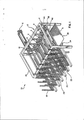
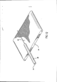
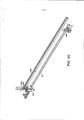
[0032] A Figura 1 é uma vista em perspectiva de uma modalidade exemplificativa de um bobinador da presente invenção. Esse bobinador inclui uma pluralidade de módulos de bobinamento independentes, que estão posicionados na direção da trama com respeito uns aos outros e substancialmente contidos dentro de uma armação modular.[0032] Figure 1 is a perspective view of an exemplary embodiment of a winder of the present invention. This winder includes a plurality of independent winding modules, which are positioned in the weft direction with respect to each other and substantially contained within a modular frame.
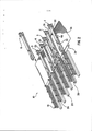
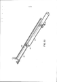
[0033] A Figura 2 é uma vista em perspectiva de uma modalidade exemplificativa de um bobinador da presente invenção. Esse desenho mostra uma pluralidade de módulos de bobinamento independentes, que estão realizando as várias funções de um ciclo de bobinamento de tora.[0033] Figure 2 is a perspective view of an exemplary embodiment of a winder of the present invention. This drawing shows a plurality of independent winding modules, which are performing the various functions of a log winding cycle.
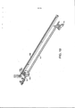
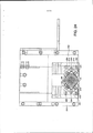
[0034] A Figura 3 é uma vista em planta de uma modalidade exemplificativa de um bobinador da presente invenção. O desenho mostra uma pluralidade de módulos de bobinamento independentes linearmente situados com respeito uns aos outros e realizando as várias funções de um ciclo de bobinamento de tora.[0034] Figure 3 is a plan view of an exemplary embodiment of a winder of the present invention. The drawing shows a plurality of independent winding modules linearly situated with respect to each other and performing the various functions of a log winding cycle.
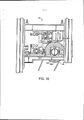
[0035] A Figura 4 é uma vista de elevação frontal de urna modalidade exemplificativa de um bobinador da presente invenção. O desenho mostra uma pluralidade de módulos de bobinamento independentes linearmente situados com respeito uns aos outros e realizando as várias funções de um ciclo de bobinamento de tora.[0035] Figure 4 is a front elevation view of an exemplary embodiment of a winder of the present invention. The drawing shows a plurality of independent winding modules linearly situated with respect to each other and performing the various functions of a log winding cycle.
[0036] A Figura 5 é uma vista de elevação lateral de uma modalidade exemplificativa de um bobinador da presente invenção. O desenho mostra uma pluralidade de módulos de bobinamento em adição a outros módulos, que realizam funções em uma trama.[0036] Figure 5 is a side elevation view of an exemplary embodiment of a winder of the present invention. The drawing shows a plurality of winding modules in addition to other modules, which perform functions in a frame.
[0037] A Figura 6 é uma vista de elevação lateral de uma modalidade exemplificativa de um módulo de bobinamento independente de acordo com a presente invenção. O desenho mostra o módulo de bobinamento se engatando a uma trama e formando um produto enrolado.[0037] Figure 6 is a side elevation view of an exemplary embodiment of an independent winding module according to the present invention. The drawing shows the winding module engaging a web and forming a rolled product.
[0038] A Figura 7 é uma vista de elevação lateral de uma modalidade exemplificativa de um módulo de bobinamento de acordo com a presente invenção. O desenho mostra o módulo de bobinamento usando rolos para formar um produto enrolado somente via bobinamento de superfície.[0038] Figure 7 is a side elevation view of an exemplary embodiment of a winding module according to the present invention. The drawing shows the winding module using rolls to form a wound product via surface winding only.
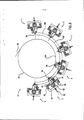
[0039] A Figura 8 é uma elevação lateral de uma modalidade exemplificativa de um bobinador de acordo com a presente invenção. O desenho mostra uma pluralidade de módulos de bobinamento independentes estando situados radialmente com respeito uns aos outros e interagindo com um aparelho de transporte de trama circular.[0039] Figure 8 is a side elevation of an exemplary embodiment of a winder according to the present invention. The drawing shows a plurality of independent winding modules being located radially with respect to each other and interacting with a circular weft conveyor apparatus.
[0040] A Figura 9 é uma vista de elevação lateral de uma modalidade exemplificativa de um módulo de bobinamento independente de acordo com a presente invenção. O desenho mostra um módulo de bobinamento que interage com um aparelho de transporte de trama circular.[0040] Figure 9 is a side elevation view of an exemplary embodiment of an independent winding module according to the present invention. The drawing shows a winding module that interacts with a circular weft transport apparatus.
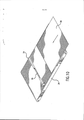
[0041] A Figura 10 é uma vista em perspectiva de uma trama sendo transportada por um aparelho de transporte de trama para proximidade com um mandril apresentando um núcleo.[0041] Figure 10 is a perspective view of a web being transported by a web transport apparatus for proximity to a mandrel having a core.
[0042] A Figura 11 é uma vista em perspectiva de um mandril rotativo e núcleo, que estão bobinando uma trama.[0042] Figure 11 is a perspective view of a rotating mandrel and core, which are winding a weft.
[0043] A Figura 12 é uma vista em perspectiva de um produto enrolado com um núcleo, que é mostrado sendo extraído de um mandril.[0043] Figure 12 is a perspective view of a rolled product with a core, which is shown being extracted from a mandrel.
[0044] A Figura 13 é uma vista em perspectiva de um mandril, que está em posição para carregamento de um núcleo.[0044] Figure 13 is a perspective view of a mandrel, which is in position for loading a core.
[0045] A Figura 14 é uma vista em perspectiva, que mostra um núcleo sendo carregado por sobre um mandril através de um aparelho de carregamento de núcleo.[0045] Figure 14 is a perspective view showing a core being loaded over a mandrel through a core loading apparatus.
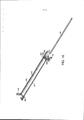
[0046] A Figura 15 é uma vista lateral de uma modalidade de um aparelho para rompimento de uma trama em movimento.[0046] Figure 15 is a side view of one embodiment of an apparatus for breaking a moving web.
[0047] As Figuras 16 até 23 são vistas em perspectiva de uma modalidade alternativa de um aparelho de carregamento de núcleo mostrando sequencialmente um núcleo sendo carregado por sobre um mandril e, então, sendo extraído do mandril.[0047] Figures 16 through 23 are perspective views of an alternative embodiment of a core loading apparatus showing sequentially a core being loaded over a mandrel and then being extracted from the mandrel.
[0048] A Figura 24 é uma vista lateral do conjunto de carregamento de núcleo ilustrado nas Figuras 16 até 23.[0048] Figure 24 is a side view of the core loading assembly illustrated in Figures 16 through 23.
[0049] Agora, será feita referência em detalhes a modalidades exemplificativas da invenção, um ou mais exemplos dos quais são ilustrados nos desenhos. Cada exemplo é fornecido por meio de explicação da invenção, e não são entendidos como uma limitação da invenção. Por exemplo, características, ilustradas ou descritas como parte de uma modalidade exemplificativa, podem ser usadas com outra modalidade exemplificativa, para produzir ainda uma terceira modalidade exemplificativa. Pretende-se que a presente invenção inclua essas e outras modificações e variações.[0049] Reference will now be made in detail to exemplary embodiments of the invention, one or more examples of which are illustrated in the drawings. Each example is provided by way of explaining the invention, and is not intended as a limitation of the invention. For example, features, illustrated or described as part of one exemplary embodiment, can be used with another exemplary embodiment to produce a still third exemplary embodiment. It is intended that the present invention include these and other modifications and variations.
[0050] Um bobinador é fornecido na presente invenção, que é capaz de bobinar a trama diretamente a partir de um rolo-mãe, para formar um produto enrolado. O bobinador pode compreender um módulo de bobinamento, que apresenta um mandril rotativo, que se engata à borda de ataque de uma trama em movimento. Quando da transferência da borda de ataque da trama para o núcleo, o mandril de bobinamento é desengatado do aparelho de transporte removendo qualquer pressão de nip para o restante da bobina. A trama pode ser enrolada em torno do núcleo através da rotação do mandril impelido de centro. Esse tipo de bobinamento é conhecido como bobinamento de centro. Adicionalmente, o mandril pode ser colocado por sobre a trama para formar e manter pressão de nip entre o mandril de bobinamento e a trama. A trama pode ser enrolada em torno do núcleo através da rotação do mandril impelido de superfície. Esse tipo de bobinamento é uma forma de bobinamento de superfície. Como tal, o módulo de bobinamento da presente invenção pode enrolar trama para formar um produto enrolado por bobinamento de centro, bobinamento de superfície e combinações de bobinamento de centro e de superfície. Isso propicia a produção de produtos enrolados com graus variáveis de maciez e firmeza.[0050] A winder is provided in the present invention, which is capable of winding the web directly from a mother roll, to form a wound product. The winder may comprise a winding module having a rotating mandrel which engages the leading edge of a moving weft. When transferring the leading edge of the web to the core, the winding mandrel is disengaged from the conveyor apparatus removing any nip pressure for the remainder of the bobbin. The weft can be wound around the core by rotating the center driven mandrel. This type of winding is known as center winding. Additionally, the mandrel can be placed over the web to form and maintain nip pressure between the winding mandrel and the web. The web can be wound around the core by rotating the surface propelled mandrel. This type of winding is a form of surface winding. As such, the winding module of the present invention can wind weft to form a wound product by center winding, surface winding and combinations of center and surface winding. This enables the production of rolled products with varying degrees of softness and firmness.
[0051] Por exemplo, em uma modalidade, o aparelho de bobinamento pode incluir um mandril de impelido e uma correia transportadora impelida e o aparelho pode incluir controle sobre a posição do mandril, o controle de impulsão do mandril e o controle de impulsão da correia transportadora de uma maneira que controle a tensão de trama, as forças no nip e a geração de torque entre o impulso de centro e o impulso de superfície para aumentar a capacidade de bobinamento de produto. Dessa maneira, por exemplo, o aparelho pode ser usado para produzir produtos apresentando volumes de rolos relativamente baixos, produtos apresentando volumes de rolos relativamente elevados, e produtos apresentando volumes de rolos em qualquer ponto entre esses extremos. Em adição, o controle aperfeiçoado sobre condições de bobinamento também propicia resistências de perfuração reduzidas, quando da produção de produtos perfurados. De particular vantagem, todos os produtos acima podem ser produzidos em velocidades relativamente rápidas, tais como em velocidades maiores do que 457,2 m/min (1.500 pés por minuto), tal como em- velocidades maiores do que 548,6 m/min (1.800 pés por minuto), tal como mesmo em velocidades maiores do que 609,6 m/min (2.000 Pés por minuto).[0051] For example, in one embodiment, the winding apparatus may include a propelled mandrel and a propelled conveyor belt and the apparatus may include control over the position of the mandrel, the mandrel thrust control and the belt thrust control conveyor in a way that controls weft tension, nip forces, and torque generation between center thrust and surface thrust to increase product winding capacity. In this way, for example, the apparatus can be used to produce products having relatively low roll volumes, products having relatively high roll volumes, and products having roll volumes anywhere between these extremes. In addition, the improved control over winding conditions also provides for reduced puncture strengths when producing perforated products. Of particular advantage, all of the above products can be produced at relatively fast speeds, such as at speeds greater than 457.2 m/min (1,500 ft per minute), such as at speeds greater than 548.6 m/min (1,800 ft per minute), such as even at speeds greater than 609.6 m/min (2,000 ft per minute).
[0052] Além disso, a presente invenção propicia um bobinador que apresenta uma pluralidade de módulos de bobinamento independentes. Cada módulo de bobinamento individual pode enrolar a trama, tal que, se um ou mais módulos forem desabilitados, os módulos restantes podem continuar a enrolar sem interrupção. Isso permite que assistência do operador e manutenção de rotina ou reparos de um módulo sejam feitos sem paralisação do bobinador. Essa configuração apresenta a vantagem particular pelo fato de que resíduos sejam eliminados e a eficiência e a velocidade da produção do produto enrolado sejam aperfeiçoadas.[0052] In addition, the present invention provides a winder that has a plurality of independent winding modules. Each individual winding module can wind the weft, such that if one or more modules are disabled, the remaining modules can continue to wind without interruption. This allows operator assistance and routine maintenance or repairs to a module to be done without downtime of the winder. This configuration has the particular advantage in that waste is eliminated and the efficiency and speed of production of the rolled product is improved.
[0053] A presente invenção faz uso de um módulo de bobinamento 12, conforme mostrado na Figura 1, a fim de enrolar uma trama 36 e formar um produto enrolado 22. Embora uma pluralidade de módulos de bobinamento independentes 12 possa ser usada na presente invenção, para produzir produtos enrolados 22, a explicação do funcionamento de somente um módulo de bobinamento 12 é necessária, a fim de se entender o processo de construção do produto enrolado 22.[0053] The present invention makes use of a winding
[0054] Referindo-se à Figura 5, uma trama 36 é transportada por um aparelho de transporte de trama 34, conforme mostrado. A trama 36 é cortada em um comprimento predeterminado por uso de, por exemplo, um módulo de corte (cut-off) 60 que pode ser configurado como uma barra de aperto (pinch), conforme descrito na Patente U.S. No. 6.056.229. No entanto, qualquer outra maneira adequada para cortar a trama 36 em um comprimento desejado pode ser empregada. Por exemplo, outra modalidade de um módulo de corte 60, de acordo com a presente invenção, é mostrada na Figura 15, a qual será descrita em maiores detalhes abaixo. Adicionalmente, a trama 36 pode ser perfurada por um módulo de perfuração 64 e ter um adesivo aplicado a ela por um módulo aplicador de adesivo de vedação de transferência/cauda 62, conforme também mostrado na Figura 5. Adicionalmente, em outras modalidades exemplificativas, adesivo pode ser aplicado ao núcleo 24, conforme oposto à trama 36. Referindo-se novamente à Figura 10, o mandril 26 é acelerado, de modo que a velocidade do mandril 26 corresponda à velocidade da trama 36. O mandril 26 apresenta um núcleo 24 localizado sobre ele. O mandril 26 é abaixado para uma posição pronta para enrolar e aguarda a trama 36. O núcleo 24 é movido para entrar em contato com a borda de ataque da trama 36. A trama 36 é, então, enrolada por sobre o núcleo 24 e é fixada ao núcleo 24, por exemplo, pelo adesivo previamente aplicado e/ou pelo contato entre o núcleo 24 e a trama 36.[0054] Referring to Figure 5, a
[0055] A Figura 11 mostra a trama 36 sendo enrolada por sobre o núcleo 24. O bobinamento da trama 36 por sobre o núcleo 24 pode ser controlado pela compressão do núcleo 24 por contra o aparelho de transporte de trama 34 para formar um nip. A magnitude com a qual o núcleo 24 é comprimido contra o aparelho de transporte de trama 34 cria uma pressão de nip, que pode controlar bobinamento da trama 36 por sobre o núcleo 24. Adicionalmente, a tensão que chega da trama 36 pode ser controlada a fim de efetuar bobinamento da trama 36 por sobre o núcleo 24. Outro controle que é possível para enrolar a trama 36 por sobre o núcleo 24 envolve o torque do mandril 26. A variação do torque sobre o mandril 26 causará uma variação no bobinamento da trama 36 por sobre o núcleo 24. Todos os três desses tipos de controles de bobinamento, "nip, tensão e diferencial de torque", podem ser empregados na presente invenção. Além disso, o bobinamento da trama 36 pode ser afetada simplesmente usando um ou mais desses controles. A presente invenção, portanto, permite que qualquer combinação de controles de bobinamento seja empregada a fim de enrolar a trama 36.[0055] Figure 11 shows the
[0056] Se não feito antes, a trama 36 pode ser cortada, uma vez que o comprimento desejado de trama 36 tenha sido enrolado por sobre o núcleo 24. Nesse ponto, a borda de ataque da próxima trama 36 será movida pelo aparelho de transporte de trama 34 para entrar em contato com outro módulo de bobinamento 12.[0056] If not done before, the
[0057] A Figura 12 mostra o mandril 26 sendo movido a partir de um local imediatamente adjacente ao aparelho de transporte de trama 34, na Figura 10, para uma posição ligeiramente acima do aparelho de transporte de trama 34. O comprimento enrolado da trama 36 é mostrado na Figura 12, como sendo um produto enrolado 38 com um núcleo 24. Agora, uma função de extração é realizada, que move o produto enrolado 38 com um núcleo 24 para fora do mandril 26. Esse mecanismo é mostrado como um aparelho de extração de produto 28, na Figura 2. O produto enrolado 38, com um núcleo 24, é movido por sobre um aparelho de transporte de produto enrolado 20, conforme mostrado nas Figuras 12.[0057] Figure 12 shows the
[0058] Uma vez que o produto enrolado 38, com um núcleo 24, seja extraído do mandril 26, o mandril 26 é movido para uma posição de carregamento de núcleo, conforme mostrado na Figura 13. O aparelho de extração de produto 28 é mostrado em mais detalhes na Figura 2. Uma vez que o aparelho de extração de produto 28 acabe a extração do produto enrolado 38, com um núcleo 24, o aparelho de extração de produto 28 é posicionado na extremidade do mandril 26. Esse posicionamento atua para estabilizar o mandril 26 e impedi-lo de se mover devido à configuração de cantilever do mandril 26. Em adição, o aparelho de extração de produto 28 auxilia a posicionar apropriadamente o ponto de extremidade de mandril 26 para o carregamento de um núcleo 24.[0058] Once the rolled
[0059] A Figura 14 mostra uma modalidade de um núcleo 24 sendo carregado por sobre o mandril 26. O carregamento do núcleo 24 é afetado por um aparelho de carregamento de núcleo 32. O aparelho de extração de produto também pode servir como um aparelho de carregamento de núcleo. O aparelho de carregamento de núcleo 32 pode ser simplesmente um engate friccional entre o aparelho de carregamento de núcleo 32 e o núcleo 24. No entanto, o aparelho de carregamento de núcleo 32 pode ser configurado de outras maneiras conhecidas na técnica. Por exemplo, outra modalidade de um aparelho de carregamento de núcleo, feito de acordo com a presente invenção, é mostrada nas Figuras 16-24, a qual será descrita em maiores detalhes abaixo. Em uma modalidade da presente invenção, uma vez que o núcleo 24 seja carregado, um braço de acoplamento (cupping) 70 (mostrado na Figura 6) se fecha. Quando do carregamento do núcleo 24 por sobre o mandril 26, o mandril 26 é movido para a posição pronta para enrolar, conforme mostrado na Figura 10. Os núcleos 24 são posicionados em um aparelho de fornecimento de núcleo 18, conforme mostrado nas Figuras, 1, 2, 3 e 4.[0059] Figure 14 shows an embodiment of a core 24 being loaded over the
[0060] A Figura 1 mostra uma modalidade exemplificativa de um bobinador de acordo com a invenção, como um "rebobinador" 10 com uma pluralidade de módulos de bobinamento 12 independentes, dispostos de uma maneira linear com respeito uns aos outros. Uma armação 14 suporta a pluralidade de módulos de bobinamento 12 independentes. Um aparelho de transporte de trama 34 está presente, o qual transporta a trama 36 para contato eventual com a pluralidade de módulos de bobinamento 12 independentes. A armação 14 é composta por uma pluralidade de montantes 16, por sobre os quais a pluralidade de módulos de bobinamento 12 independentes são engatados de maneira deslizável e suportados. A armação 14 também pode compreender seções de armações modulares, que se engatariam a cada uma outra para formar uma estrutura rígida. O número de seções de armações modulares coincidiria com o número de módulos de bobinamento utilizados.[0060] Figure 1 shows an exemplary embodiment of a winder according to the invention, as a "rewinder" 10 with a plurality of independent winding
[0061] Situada adjacente à armação 14 há uma série de aparelhos de fornecimento de núcleo 18. Uma pluralidade de núcleos 24 pode ser incluída dentro de cada aparelho de fornecimento de núcleo 18. Esses núcleos 24 podem ser usados pela pluralidade de módulos de bobinamento 12 independentes para formar produtos enrolados 22. Uma vez formados, os produtos enrolados 22 podem ser removidos da pluralidade de módulos de bobinamento 12 independentes e colocados por sobre um aparelho de transporte de produto enrolado 20. O aparelho de transporte de produto enrolado 20 é posicionado próximo à armação 14 e ao aparelho de transporte de trama 34.[0061] Situated adjacent to frame 14 are a series of
[0062] A Figura 2 mostra um bobinador 10 conforme substancialmente descrito na Figura 1, mas apresentando a armação 14 e outras partes removidas por clareza. Nessa modalidade exemplificativa, a pluralidade de módulos de bobinamento 12 independentes é composta por seis módulos de bobinamento 1-6. Entretanto, deve ser entendido que a presente invenção inclui modalidades exemplificativas apresentando qualquer número de módulos de bobinamento 12 independentes sendo diferente de seis em número, por exemplo, somente um módulo de bobinamento 12 pode ser usado em outra modalidade exemplificativa.[0062] Figure 2 shows a
[0063] Cada módulo de bobinamento 1-6 é mostrado realizando uma função diferente. O módulo de bobinamento 1 é mostrado no processo de carregamento de um núcleo 24 sobre ele. A pluralidade de módulos de bobinamento 12 independentes é dotada com um aparelho de carregamento de núcleo para posicionamento de um núcleo 24 por sobre um mandril 26, da pluralidade de módulos de bobinamento 12 independentes. Qualquer número de variações de um aparelho de carregamento de núcleo pode ser utilizado em outras modalidades exemplificativas da presente invenção. Por exemplo, o aparelho de carregamento de núcleo pode ser uma combinação de uma haste que se estende para o aparelho de fornecimento de núcleo 18 e empurra um núcleo 24 parcialmente por sobre o mandril 26 e um mecanismo fixado ao atuador linear do aparelho de extração de produto 28, que se engata friccionalmente e puxa o núcleo 24 pela distância restante por sobre o mandril 26. Conforme mostrado na Figura 2, o módulo de bobinamento 1 está no processo de puxar um núcleo 24 do aparelho de fornecimento de núcleo 18 e posicionar o núcleo 24 sobre o mandril 26.[0063] Each winding module 1-6 is shown performing a different function. The winding module 1 is shown in the process of loading a core 24 onto it. The plurality of independent winding
[0064] Referindo-se às Figuras 16-24, é mostrada uma modalidade de um aparelho de carregamento de núcleo, que pode ser usado de acordo com a presente invenção. Em particular, as Figuras 16-23 ilustram uma sequência de carregamento de um núcleo 24 por sobre um mandril 26, a fim de formar um produto enrolado 22, que, então, é extraído do mandril 26.[0064] Referring to Figures 16-24, an embodiment of a core loading apparatus which can be used in accordance with the present invention is shown. In particular, Figures 16-23 illustrate a sequence of loading a core 24 onto a
[0065] Conforme mostrado na Figura 16, o aparelho de carregamento de núcleo inclui um conjunto de carregamento de núcleo 200, que desliza para trás e para frente através do mandril 26. O conjunto de carregamento de núcleo 200 inclui um dispositivo de agarramento 202 para engatar o núcleo 24 e, opcionalmente, do estabilizador 204. O conjunto de carregamento de núcleo 200 é fixado a um atuador 208, tal como um atuador linear, conforme mostrado. Em particular, o conjunto de carregamento de núcleo 200 é montado ao atuador linear, que é posicionado paralelo ao mandril 26. O atuador 208 inclui um motor 210, que impele uma trilha 212. A trilha 212 é fixada ao conjunto de carregamento de núcleo 200, tal que o conjunto de carregamento de núcleo atravesse para trás e para frente o mandril 26, conforme o motor 206 impulsione a trilha 212. A trilha 212 pode compreender, por exemplo, uma correia, conforme mostrado ou pode ser uma corrente ou qualquer outro dispositivo adequado.[0065] As shown in Figure 16, the core loading apparatus includes a
[0066] Em adição ao atuador linear 208, conforme mostrado na Figura 16, deve ser entendido que qualquer atuador adequado pode ser usado, que seja capaz de mover o conjunto de carregamento de núcleo 200 ao longo do mandril 26. Por exemplo, em outras modalidades, pode ser usado um atuador pneumático ou hidráulico. Alternativamente, um parafuso de esfera ou os similares podem ser usados como o atuador.[0066] In addition to the
[0067] O mandril 26, conforme mostrado, é suportado em uma extremidade por um mancal 214. Na extremidade oposta, o mandril 26 é engatável com um braço de acoplamento 70. O braço de acoplamento 70 está em comunicação com um motor 206. O motor 206 faz com que o braço de acoplamento gire, por meio disto se engatando com a, e se desengatando da, extremidade do mandril 26. Por exemplo, na Figura 20, o braço de acoplamento 70 é mostrado na posição engatada para suportar a extremidade do mandril 26. O braço de acoplamento 70 é usado para engatar e suportar a extremidade do mandril 26 durante o bobinamento. Quando do carregamento do núcleo 24 ou quando da extração de um produto enrolado do mandril 26, por outro lado, o braço de acoplamento 70 se desengata do mandril 26. Quando o braço de acoplamento 70 é desengatado do mandril 26, o estabilizador 204 do conjunto de carregamento de núcleo se engata com o mandril para suportar o mandril, enquanto um núcleo estiver sendo carregado.[0067] The
[0068] Conforme ilustrado na Figura 16, o dispositivo de agarramento 202 e o estabilizador 204 estão contidos dentro de um alojamento 216 para formar o conjunto de carregamento de núcleo 200. Uma vista ampliada, do dispositivo de agarramento 202 e do estabilizador 204 com o alojamento removido, é mostrada na Figura 18. Uma vista de seção transversal do dispositivo de agarramento 202 também é ilustrada na Figura 24. Conforme mostrado na Figura 24, o dispositivo de agarramento 202 inclui membros de agarramento 218, que se pretende que circundem e agarrem o núcleo 24. Na modalidade ilustrada na Figura 24, quatro membros de agarramento 218 são mostrados. Deve ser entendido, contudo, que um maior ou menor número de membros de agarramento pode ser utilizado. Os membros de agarramento são móveis em direção a, e para longe uns dos outros para agarramento e liberação do núcleo 24.[0068] As shown in Figure 16, the
[0069] Por exemplo, em uma modalidade, os membros de agarramento 218 podem ser atuados pneumaticamente ou hidraulicamente. A esse respeito, conforme mostrado na Figura 18, o dispositivo de agarramento 202 inclui uma entrada de fluido 220 e uma saída de fluido 222. A entrada de fluido 220 e a saída de fluido 222 são para escoamento de um fluido para dentro e para fora do dispositivo de agarramento 202 para mover, respectivamente, os membros de agarramento 218 em direção a, e para longe uns dos outros.[0069] For example, in one embodiment, the gripping
[0070] Na modalidade ilustrada na Figura 24, os membros de agarramento 218, de maneira geral, formam um formato de seção transversal semelhante a retângulo para engate com o núcleo 24. Entretanto, deve ser entendido que pode ser utilizado qualquer formato de seção transversal adequado capaz de circundar o núcleo 24 para engate com o núcleo. Por exemplo, em uma modalidade alternativa, o dispositivo de agarramento 202 pode incluir somente dois membros de agarramento que apresentem um formato semelhante a arco.[0070] In the embodiment illustrated in Figure 24, the gripping
[0071] Pretende-se que os membros de agarramento 218 do dispositivo de agarramento 202 se engatem e segurem o núcleo 24 para puxar o núcleo por sobre o mandril 26 sem danificar o núcleo. Por exemplo, tendo- se os membros de agarramento 218 sendo controlados por fluido permitem-se ajustes finos na quantidade de pressão sendo colocada no núcleo 24. Em adição, os membros de agarramento 218 podem pivotar, o que possibilita que os membros de agarramento se acomodem por algum desalinhamento.The gripping
[0072] Por exemplo, conforme mostrado na Figura 24, o dispositivo de agarramento 202 inclui um primeiro membro de pivô 223 definindo um primeiro ponto de pivô 224 e um segundo membro de pivô 225 definindo um segundo ponto de pivô 226. Em adição, o dispositivo de agarramento 202 inclui quatro molas 228. Mais particularmente, o ponto de pivô 224 é circundado por uma mola superior e inferior 228, enquanto que o ponto de pivô 226 também é circundado por uma mola superior e inferior 228. Os pontos de pivô e as molas permitem que aos membros de pivô 223 e 225 e, portanto, aos membros de agarramento 218, alguma flexibilidade de movimento. Mais particularmente, o par direito de membros de agarramento 218 pode pivotar em torno do ponto de pivô 224, enquanto que o par esquerdo de membros de agarramento 218 pode pivotar em torno do ponto de pivô 226. Dessa maneira, quando o núcleo 24 for engatado pelos membros de agarramento, os membros de agarramento podem não somente se mover para trás e para frente, mas também podem pivotar para puxar o núcleo por sobre o mandril sem desalinhamento e sem danificar o núcleo.[0072] For example, as shown in Figure 24, the
[0073] Os membros de agarramento 218 podem ser feitos a partir de qualquer material adequado capaz de se engatar com o núcleo 24 sem danificar o núcleo. Os membros de agarramento 218, por exemplo, podem ser feitos a partir de qualquer material rígido ou macio adequado. Em uma modalidade particular, por exemplo, os membros de agarramento 218 podem ser feitos a partir de um metal.Gripping
[0074] Conforme mostrado na Figura 18, o conjunto de carregamento de núcleo 200 também inclui o estabilizador 204. O estabilizador 204 pode ser incluído no conjunto a fim de estabilizar o mandril, conforme o núcleo está sendo carregado por sobre o mandril. Em uma modalidade, conforme mostrado na Figura 18, o estabilizador 204, de maneira geral, pode apresentar a mesma construção que o dispositivo de agarramento 202. Por exemplo, o estabilizador 204 pode incluir pelo menos dois membros de estabilização, que se engatam de maneira deslizável com o mandril 26 e se movem em direção a, e para longe uns dos outros por escoamento de um fluido através de uma entrada de fluido 230 e de uma saída de fluido 232. Em uma modalidade, o estabilizador 204 pode incluir quatro membros de estabilização apresentando a mesma configuração exata que os membros de agarramento 218. Os membros de estabilização, entretanto, são para engate de maneira deslizante com o mandril 26. A esse respeito, os membros de estabilização podem apresentar uma superfície de baixo atrito feita de um material lubrificante, tal como uma poliolefina. Os membros de estabilização, por exemplo, podem incluir uma superfície de polietileno ou de polipropileno, que deslize entre o mandril 26, conforme o núcleo 24 seja carregado.[0074] As shown in Figure 18, the
[0075] O conjunto de carregamento de núcleo 200 e o atuador 208 podem ser posicionados em comunicação com um controlador, tal como um microprocessador, que seja capaz de atuar uma sequência para carregamento de um núcleo por sobre o mandril em uma posição desejada e, então, extrair um produto enrolado a partir do material. Uma sequência para carregamento de um núcleo por sobre o mandril é ilustrada nas Figuras 16-23.[0075] The
[0076] Por exemplo, conforme mostrado na Figura 16, a fim de carregar o núcleo 24 por sobre o mandril 26, o braço de acoplamento 70 é primeiramente desengatado do mandril 26 e o conjunto de carregamento de núcleo 200 é posicionado na extremidade aberta do mandril 26. Dessa maneira, não somente o conjunto de carregamento de núcleo 200 está em uma posição para engate com o núcleo 24, mas, também, estabiliza o mandril 26, quando o braço de acoplamento 70 for desengatado.[0076] For example, as shown in Figure 16, in order to load the core 24 over the
[0077] Conforme mostrado nas Figuras 17 e 18, o dispositivo de agarramento 202 circunda uma circunferência externa do núcleo 24 para engate com o núcleo. O núcleo pode ser fornecido ao dispositivo de agarramento a partir de um aparelho de fornecimento de núcleo.[0077] As shown in Figures 17 and 18, the
[0078] Uma vez que o núcleo esteja engatado, o núcleo 24 é puxado por sobre o mandril 26, conforme mostrado na Figura 19 usando o atuador 208. O atuador 208 pode ser configurado para posicionar o núcleo 24 em uma posição particular sobre o mandril 26. Uma vez que o núcleo 24 esteja posicionado em uma posição particular, o dispositivo de agarramento 202 pode liberar o núcleo, conforme mostrado na Figura 20. O conjunto de carregamento de núcleo 200 é, então, movido adicionalmente para a extremidade do mandril, para prevenir a interferência com o núcleo 24, conforme a trama de material seja enrolada por sobre o núcleo. Além disso, conforme mostrado na Figura 20, o braço de acoplamento 70 é movido de volta para engate com o mandril 26.[0078] Once the core is engaged, the
[0079] Uma vez que o núcleo 24 seja carregado por sobre o mandril 26, conforme mostrado na Figura 20, um produto enrolado 22 é formado sobre o mandril, conforme mostrado na Figura 21. De particular vantagem, nessa modalidade, o conjunto de carregamento de núcleo 200 também pode ser usado para extrair o produto enrolado 22 do mandril 26. Por exemplo, conforme mostrado na Figura 22, uma vez que o produto enrolado 22 é formado, o atuador 208 pode mover o conjunto de carregamento de núcleo 200 para engate com o produto enrolado para deslizar para fora o produto enrolado do mandril 26, conforme mostrado na Figura 23. O produto enrolado 22, uma vez extraído do mandril 26 pode, então, ser alimentado a um aparelho de transferência de produto enrolado. De particular vantagem, o conjunto de carregamento de núcleo 200 estabiliza o mandril conforme ele empurra o produto enrolado para fora do mandril. Em particular, o conjunto de carregamento de núcleo 200 mantém a extremidade livre aberta do mandril, o que reduz o arranque (whip) do mandril e, portanto, evita contra desalinhamentos. Adicionalmente, uma vez que o produto enrolado é extraído do mandril, o conjunto de carregamento de núcleo 200 está em uma posição para engate e para puxar um novo núcleo por sobre o mandril.[0079] Once the
[0080] O aparelho de carregamento de núcleo descrito acima pode fornecer vários benefícios e vantagens quando da formação dos produtos enrolados. Por exemplo, o aparelho de carregamento de núcleo, conforme descrito acima, é capaz de puxar os núcleos por sobre o mandril para uma posição fixa. Em adição, o mandril é estabilizado e mantido em posição durante o processo de carregamento. Por minimização de mudanças de posição do núcleo e do mandril, a probabilidade de carregamento de núcleo bem sucedido é vastamente aperfeiçoada, o que maximiza a produtividade e minimiza os resíduos, com respeito às operações de carregamento de núcleo. Além disso, o aparelho de carregamento de núcleo, conforme descrito acima, é condizente a várias condições de material e rigidez de núcleo. Por exemplo, núcleos moles ou flácidos podem ser puxados por sobre mandris ao invés de material de papel rígido, se desejado. Em adição, o aparelho de carregamento de núcleo também serve como um dispositivo de extração de tora depois que o produto enrolado seja formado. Essa dupla função é vantajosa porque ela simplifica o projeto e minimiza as ferragens.[0080] The core loading apparatus described above can provide various benefits and advantages when forming the rolled products. For example, the core loading apparatus as described above is capable of pulling the cores over the mandrel to a fixed position. In addition, the mandrel is stabilized and held in position during the loading process. By minimizing core and mandrel position changes, the probability of successful core loading is vastly improved, which maximizes productivity and minimizes waste, with respect to core loading operations. In addition, the core loading apparatus, as described above, is suited to various core material and stiffness conditions. For example, soft or flabby cores can be pulled over mandrels rather than stiff paper material if desired. In addition, the core loading apparatus also serves as a log extraction device after the rolled product is formed. This dual function is advantageous because it simplifies design and minimizes hardware.
[0081] Referindo-se novamente à Figura 2, o módulo de bobinamento 2 é mostrado como tendo-se removido o produto enrolado 22 de seu mandril 26. O produto enrolado 22 é colocado por sobre um aparelho de transporte de produto enrolado 20. Nesse caso, o produto enrolado 22 é um produto enrolado com um núcleo 38. Um tal produto enrolado com um núcleo 38 é um produto enrolado 22, que é formado tendo-se a trama 36 sendo embrulhada de maneira espiral em torno de um núcleo 24. Deve ser entendido que o produto enrolado 22 também pode ser um produto enrolado que não apresenta um núcleo 24 e, ao invés disto, é simplesmente um rolo sódio de trama enrolada 36. Também pode ser o caso que o produto enrolado 22, formado pela presente invenção, não inclua um núcleo 24, mas apresente uma cavidade no centro do produto enrolado 22. Várias configurações de produto enrolado 22 podem, portanto, ser formadas de acordo com a presente invenção.[0081] Referring again to Figure 2, the winding
[0082] Cada um da pluralidade de módulos de bobinamento 12 independentes é dotado com um aparelho de extração de produto 28, que é usado para remover o produto enrolado 22 dos módulos de bobinamento 1-6. O módulo de bobinamento 3 é mostrado como estando no processo de extração de um produto enrolado 22 a partir do módulo de bobinamento 3. O aparelho de extração de produto 28 é mostrado como sendo um flange, que estabiliza o mandril 26 e entra em contato com uma extremidade do produto enrolado 22 e empurra o produto enrolado 22 para fora do mandril 26. Além disso, o aparelho de extração de produto 28 auxilia a posicionar a extremidade do mandril 26 na posição apropriada para o carregamento de um núcleo 24. O aparelho de extração de produto enrolado 28, portanto, é um aparelho mecânico que se move na direção do aparelho de transporte de produto enrolado 20. O aparelho de extração de produto 28 pode ser configurado de maneira diferente em outras modalidades exemplificativas da invenção.[0082] Each of the plurality of independent winding
[0083] O módulo de bobinamento 4 é mostrado como estando no processo de bobinamento da trama 36, a fim de formar o produto enrolado 22. Esse processo de bobinamento pode ser bobinamento de centro, bobinamento de superfície ou uma combinação de bobinamento de centro e de superfície. Esses processos serão explicados em maiores detalhes abaixo.[0083] The winding module 4 is shown as being in the process of winding the
[0084] O módulo de bobinamento 5 é mostrado em uma posição, na qual ele está pronto para enrolar a trama 36 uma vez que o módulo de bobinamento 4 termine o bobinamento da trama 36, para produzir um produto enrolado 22. Em outras palavras, o módulo de bobinamento 5 está em uma posição "pronta para enrolar".[0084] The winding
[0085] O módulo de bobinamento 6 é mostrado, na Figura 1, em uma posição "racked out". Pode ser o caso, em que o módulo de bobinamento 6 tenha falhado ou tenha a necessidade de manutenção de rotina e é, portanto, substancialmente movido para fora da armação 14 para acesso por pessoal de manutenção ou de operações. Como tal, o módulo de bobinamento 6 não está em uma posição para enrolar a trama 36, para produzir o produto enrolado 22, mas os outros cinco módulos de bobinamento 1-5 ainda são capazes de funcionar sem interrupção para produzir o produto enrolado 22. Por atuação como bobinadores individuais, a pluralidade de módulos de bobinamento 12 independentes permite a produção ininterrupta, mesmo quando um ou mais dos módulos de bobinamento se tornem desabilitados.[0085] The winding
[0086] Cada módulo de bobinamento 12 pode apresentar um aparelho de posicionamento 56 (Figura 4). O aparelho de posicionamento 56 move o módulo de bobinamento perpendicularmente com respeito ao aparelho de transporte de trama 34, e para dentro e para fora do engate com a trama 36. Embora os módulos 12 sejam mostrados como sendo movidos em uma direção substancialmente vertical, outras modalidades exemplificativas da invenção podem apresentar os módulos 12 movidos horizontalmente ou mesmo girados para posição com respeito à trama 36. Outras maneiras de posicionamento dos módulos 12 podem ser vislumbradas.[0086] Each winding
[0087] Portanto, cada um de uma pluralidade de módulos de bobinamento 12 independentes pode ser uma unidade autocontida e pode realizar as funções conforme descrito com respeito aos módulos de bobinamento 1-6. O módulo de bobinamento 1 pode carregar um núcleo 24 por sobre o mandril 26 se um núcleo 24 for desejado para o produto enrolado particular 22 sendo produzido. A seguir, o módulo de bobinamento 1 pode ser posicionado linearmente, de modo a estar em uma posição "pronta para enrolar". Além disso, o mandril 26 pode ser girado até uma velocidade rotacional desejada e, então, posicionado pelo aparelho de posicionamento 56, a fim de iniciar o contato com a trama 36. A velocidade rotacional do mandril 26 e a posição do módulo de bobinamento 1 com respeito à trama 36 podem ser controladas durante a construção do produto enrolado 22. Depois de completar o bobinamento, a posição do módulo 1 com respeito à trama 36 será variada de modo que o módulo de bobinamento 1 esteja em uma posição para efetuar a remoção do produto enrolado 22. O produto enrolado 22 pode ser removido pelo aparelho de extração de produto 28, tal que o produto enrolado 22 seja posicionado no aparelho de transporte de produto enrolado 20. Finalmente, o módulo de bobinamento 1 pode ser posicionado, tal que ele seja capaz de carregamento de um núcleo 24 por sobre o mandril 26, se assim for desejado. Novamente, se um produto enrolado incolor deve ser produzido como o produto enrolado 22, a etapa de carregamento de um núcleo 24 seria pulada. Deve ser entendido que outras modalidades exemplificativas da presente invenção podem fazer com que a operação de carregamento de núcleo 24 e a operação de extração de núcleo 24 ocorram na mesma posição ou em posições diferentes com respeito ao mandril 26.[0087] Therefore, each of a plurality of independent winding
[0088] O bobinador 10 da presente invenção pode formar produtos enrolados 22, que apresentam características variáveis por mudança do tipo de processo de bobinamento sendo utilizado. O mandril 26 impelido permite o bobinamento de centro da trama 36, a fim de produzir um produto enrolado 22 mais macio, de baixa densidade. O aparelho de posicionamento 56 em combinação com o aparelho de transporte de trama 34 permite o bobinamento de superfície da trama 36 e a produção de um produto enrolado 22 bobinado mais rígido, de alta densidade. O bobinamento de superfície é induzido pelo contato entre o núcleo 24 e a trama 36 para formar um nip 68 (mostrado na Figura 6) entre o núcleo 24 e o aparelho de transporte de trama 34. Uma vez iniciado, o nip 68 será formado entre o produto enrolado 22, conforme ele seja construído, e o aparelho de transporte de trama 34. Conforme pode ser visto, o bobinador 10 da presente invenção, portanto, propicia tanto o bobinamento de centro quanto o bobinamento de superfície, a fim de produzir produtos enrolados 22. Em adição, uma combinação de bobinamento de centro e de bobinamento de superfície pode ser utilizada, a fim de produzir um produto enrolado 22 apresentando características variáveis. Por exemplo, o bobinamento da trama 36 pode ser afetada, em parte, por rotação do mandril 26 (bobinamento de centro) e, em parte, por pressão do nip aplicada pelo posicionamento do aparelho 56 por sobre a trama 36 (bobinamento de superfície). Portanto, o bobinador 10 pode incluir uma modalidade exemplificativa que propicie bobinamento de centro, bobinamento de superfície e qualquer combinação entre elas. Adicionalmente, como uma opção a se usar um motor para controlar a velocidade/torque do mandril, pode estar presente um dispositivo de frenagem (não mostrado) sobre os módulos de bobinamento 12, a fim de controlar adicionalmente os procedimentos de bobinamento de superfície e de centro.[0088] The
[0089] A pluralidade de módulos de bobinamento 12 independentes podem ser ajustados, a fim de se acomodarem à construção do produto enrolado 22. Por exemplo, se o bobinamento de superfície fosse desejado, a pressão entre o produto enrolado 22 conforme ele estiver sendo construído e o aparelho de transporte de trama 34 pode ser ajustado pelo uso do aparelho de posicionamento 56 durante a construção do produto enrolado 22.[0089] The plurality of independent winding
[0090] Em adição a controlar o torque do mandril e a pressão do nip conforme descrito acima, a tensão de trama também pode ser controlada durante o processo. A tensão de trama pode ser controlada de várias maneiras. A tensão de trama pode ser controlada, por exemplo, por variação de uma tiragem da trama de papel tissue entre o mandril e um dispositivo de tensão à montante. O dispositivo de tensão à montante, por exemplo, pode compreender o dispositivo que desbobina o rolo-mãe ou pode compreender outro dispositivo de tensão de trama posicionado antes do aparelho de transporte de trama. Em uma modalidade, por exemplo, um dispositivo de sucção, tal como um rolo a vácuo, pode ser posicionado no sistema antes do aparelho de transporte de trama 34. A tensão de trama pode, então, ser controlada por variação da tiragem entre o mandril e o rolo a vácuo ou por variação da tiragem entre o mandril e o aparelho de transporte de trama combinados e o rolo a vácuo.[0090] In addition to controlling the chuck torque and nip pressure as described above, the weft tension can also be controlled during the process. Weft tension can be controlled in several ways. Weft tension can be controlled, for example, by varying a draw of tissue paper web between the mandrel and an upstream tensioning device. The upstream tensioning device, for example, may comprise the device which unwinds the mother roll or it may comprise another weft tensioning device positioned before the weft transport apparatus. In one embodiment, for example, a suction device, such as a vacuum roller, can be positioned in the system before the
[0091] Ao invés de, ou em adição ao acima, a tensão de trama também pode ser controlada de várias outras maneiras. Por exemplo, a tensão de trama também pode ser controlada por controle da velocidade do mandril em relação à quantidade de força sendo exercida sobre a trama de papel tissue pelo aparelho de transporte de trama.[0091] Instead of, or in addition to, the weft tension can also be controlled in a number of other ways. For example, the weft tension can also be controlled by controlling the speed of the mandrel in relation to the amount of force being exerted on the tissue paper web by the weft conveyor.
[0092] A utilização de uma pluralidade de módulos de bobinamento 12 independentes permite a um bobinador 10, que é capaz de produzir simultaneamente produto enrolado 22 apresentando atributos variáveis. Por exemplo, os produtos enrolados 22 que são produzidos podem ser feitos, tal que eles apresentem diferentes contagens de folhas. Além disso, o bobinador 10 pode ser operado em taxas de ciclo tanto elevadas quanto baixas, com os módulos 12 sendo ajustados da maneira a mais eficiente para o produto enrolado 22 sendo construído. Os módulos de bobinamento 12 da presente invenção podem apresentar controles de bobinamento específicos para cada módulo 12, com um controle de máquina comum. Mudanças em tempo real podem ser feitas, onde diferentes tipos de produtos enrolados 22 sejam produzidos sem se ter que modificar de maneira significativa ou parar o bobinador 10. Atributos de rolo em tempo real podem ser medidos e controlados. A presente invenção inclui modalidades exemplificativas que não estão limitadas à taxa de ciclo.[0092] The use of a plurality of independent winding
[0093] A presente invenção também é capaz de produzir um amplo espectro de produtos enrolados 22, e não está limitada no sentido de uma largura específica da trama 36.[0093] The present invention is also capable of producing a broad spectrum of rolled
[0094] Em uma modalidade particular, a presente- invenção é particularmente dirigida a um sistema que seja capaz de produzir produtos apresentando qualquer volume de rolo desejado dentro de uma faixa de volumes de rolo relativamente grande. O volume de rolo do produto resultante, por exemplo, pode ser controlado por controle de pelo menos um dentre a pressão de nip, da tensão que chega da trama de papel tissue e/ou do torque do mandril, conforme descrito acima. Em uma modalidade, por exemplo, somente uma das condições de processo acima pode ser controladas para variar o volume de rolo, tal como a pressão de nip. Em outra modalidade, pelo menos duas das condições de processo acima podem ser controladas para produzir produtos. Em ainda outra modalidade, todas as três das condições de processo acima podem ser controladas em conjunto para produzir um produto apresentando um volume de rolo desejado. Por exemplo, rolos mais macios apresentando níveis de volume de rolo relativamente elevados podem ser criados por redução do torque do mandril, pela redução da pressão de nip entre o mandril e o transportador de transporte e/ou pela redução da tensão que chega, que pode ser a tensão entre o mandril e um dispositivo de tensão à montante, tal como um rolo a vácuo. Inversamente, mais rolos firmes apresentando volume de rolo menor podem ser feitos por aumento do torque do mandril, por aumento da pressão de nip e/ou por aumento da tensão que chega.[0094] In a particular embodiment, the present invention is particularly directed to a system that is capable of producing products having any desired roll volume within a relatively large roll volume range. The resulting product roll volume, for example, can be controlled by controlling at least one of the nip pressure, the incoming tension from the tissue paper web and/or the mandrel torque, as described above. In one embodiment, for example, only one of the above process conditions can be controlled to vary roll volume, such as nip pressure. In another embodiment, at least two of the above process conditions can be controlled to produce products. In yet another embodiment, all three of the above process conditions can be controlled together to produce a product having a desired roll volume. For example, softer rolls having relatively high roll volume levels can be created by reducing the mandrel torque, by reducing the nip pressure between the mandrel and the transport conveyor, and/or by reducing the incoming tension, which can be the tension between the mandrel and an upstream tensioning device such as a vacuum roller. Conversely, more firm rolls having a smaller roll volume can be made by increasing the mandrel torque, by increasing the nip pressure and/or by increasing the incoming tension.
[0095] O sistema da presente invenção, por exemplo, é capaz de produzir produtos enrolados apresentando um volume de rolo em qualquer ponto entre cerca de 2 cm3/g a cerca de 14 cm3/g, tal como cerca de 3 cm3/g a cerca de 13 cm3/g. Bobinadores convencionais, tais como bobinadores impelidos de superfície ou bobinadores impelidos de centro, por outro lado, simplesmente não são capazes de produzir produtos dentro de uma tal faixa ampla de volumes de rolo de maneira eficiente ou em velocidades de produção consistentemente elevadas.[0095] The system of the present invention, for example, is capable of producing rolled products having a roll volume at any point between about 2 cm3/g to about 14 cm3/g, such as about 3 cm3/g to about 13 cm3/g. Conventional winders, such as surface driven winders or center driven winders, on the other hand, are simply not capable of producing products within such a wide range of roll volumes efficiently or at consistently high production speeds.
[0096] De vantagem particular, os produtos podem ser feitos dentro da faixa inteira de volume de rolo descrita acima sem se ter que reduzir substancialmente a velocidade do sistema. Em particular, os produtos apresentando qualquer volume de rolo desejado podem ser produzidos enquanto a trama de papel tissue estiver transitando em uma velocidade maior do que cerca de 457,2 m/min (1.500 pés/minuto), tal como maior do que cerca de 548,6 m/min (1.800 pés/minuto), tal como maior do que 609,6 m/min (2.000 pés/minuto). Em uma modalidade, por exemplo, os produtos podem ser produzidos enquanto a trama de papel tissue estiver se movendo em uma velocidade de cerca de 609,6 m/min (2.000 pés/minuto) a cerca de 914,4 m/min (3.000 pés/minuto), tal como mesmo maior do que 762 m/min (2.500 pés/minuto).[0096] Of particular advantage, products can be made within the entire range of roll volume described above without having to substantially reduce the speed of the system. In particular, products having any desired roll volume can be produced while the tissue paper web is transiting at a speed greater than about 457.2 m/min (1,500 ft/minute), such as greater than about about 548.6 m/min (1,800 ft/minute), such as greater than 609.6 m/min (2,000 ft/minute). In one modality, for example, products can be produced while the tissue paper web is moving at a speed of about 609.6 m/min (2,000 ft/minute) to about 914.4 m/min (3,000 ft/minute), such as even greater than 762 m/min (2500 ft/minute).
[0097] Em uma modalidade particular, o sistema da presente invenção é usado para produzir produtos apresentando um volume de rolo relativamente elevado tais como produtos apresentando um volume de rolo maior do que cerca de 8 cm3/g, tal como ainda maiores do que 10 cm3/g. Na produção de produtos apresentando um volume de rolo relativamente elevado, uma das vantagens do sistema da presente invenção é que a trama de papel tissue pode ser alimentada ao mandril em uma tensão de trama substancialmente igual a zero. Em adição, uma vez que o produto seja produzido no mandril, a folha de papel tissue pode ser cortada em tensão de trama muito baixa, especialmente quando se usar o módulo de corte 60, conforme mostrado na Figura 15. Em particular, a trama de papel tissue pode ser cortada em um comprimento de destaque de menos do que cerca de 2,2 N (220 gramas de força), tal como menos do que cerca de 2,0 N (200 gramas de força), tal como menos do que cerca de 1,9 N (190 gramas de força), tal como ainda menos do que cerca de 1,8 N (180 gramas de força) em uma largura de rolo de 10,6 cm (4,2 polegadas).[0097] In a particular embodiment, the system of the present invention is used to produce products having a relatively high roll volume such as products having a roll volume greater than about 8 cm3/g, such as even greater than 10 cm3/g. In producing products having a relatively high roll volume, one of the advantages of the system of the present invention is that the tissue paper web can be fed to the mandrel at a web tension substantially equal to zero. In addition, once the product is produced on the mandrel, the tissue paper sheet can be cut at very low weft tension, especially when using the
[0098] A pluralidade de módulos de bobinamento 12 independentes pode ser projetada de uma maneira tal que a manutenção possa ser realizada em qualquer um ou mais dos módulos de bobinamento 1-6, sem se ter que interromper a operação, conforme previamente discutido com o módulo de bobinamento 6. Um módulo de bobinamento 12 pode ser removido e trabalhado enquanto os restantes permanecem em operação. Adicionalmente, tendo-se uma pluralidade de módulos de bobinamento 12 independentes permite-se um aumento nos intervalas de tempo disponíveis para as funções de carregamento do núcleo 24 e para as funções de extração do produto enrolado 22. Permitindo-se um aumento nesses intervalos de tempo reduz-se grandemente a ocorrência de erros de carregamento e de extração. Além disso, aparelhos da técnica anterior experimentando interrupção da operação de bobinamento produzirão um produto enrolado 22, que não é completo. Esse resíduo, em conjunto com o resíduo criado pela mudança de um rolo- mãe ou mudança de formato de produto, será reduzido como um resultado do bobinador 10, de acordo com a presente invenção. O resíduo pode ser removido a partir da bobina 10 por uso de um aparelho de remoção de resíduo 200 (Figura 5), conforme é conhecido na técnica.[0098] The plurality of independent winding
[0099] A Figura 3 mostra um bobinador 10 apresentando uma armação 14 disposta em torno de uma pluralidade de módulos de bobinamento 12 independentes. A armação 14 apresenta uma pluralidade de elementos transversais 42 atravessando as extremidades da armação 14. O aparelho de posicionamento 56, que se comunica com os módulos de bobinamento 1-6, é engatado em uma extremidade em relação aos elementos transversais 42, conforme mostrado na Figura 4. Um membro de suporte linear vertical 44 está presente na pluralidade de módulos de bobinamento 12 independentes, a fim de fornecer um mecanismo de fixação para o aparelho de posicionamento 56 e para propiciar estabilidade aos módulos de bobinamento. O aparelho de posicionamento 56 pode ser um atuador de parafuso de enrolador impelido. No entanto, outros meios de posicionamento da pluralidade de módulos de bobinamento 12 independentes podem ser utilizados. Os membros de suporte vertical 44 também podem se engatar com um suporte de cursor linear vertical 58, que é fixado aos montantes 16 na armação 14. Uma tal conexão pode ser de várias configurações, por exemplo, um mancai linear ou uma conexão de trilho deslizante. Uma tal conexão é mostrada como um cursor linear vertical 52, que corre dentro do suporte de cursor linear vertical 58, na Figura 4.[0099] Figure 3 shows a
[00100] Um membro de suporte linear horizontal 46 também está presente na pluralidade de módulos de bobinamento 12 independentes. O membro de suporte linear horizontal 46 pode se comunicar com um cursor linear horizontal 54 (conforme mostrado na Figura 6) para permitir que alguns ou toda a pluralidade de módulos de bobinamento 12 independentes seja movida do lado de fora da armação 14. O cursor linear horizontal 54 pode ser uma conexão de tipo de trilho linear. No entanto, várias configurações são vislumbradas sob a presente invenção.[00100] A horizontal
[00101] A Figura 6 mostra uma vista em aproximação de uma modalidade exemplificativa de um módulo de bobinamento de acordo com a presente invenção. O servomotor 50 pode ser suportado pela armação de módulo 48, por sobre a qual um braço de acoplamento de mandril 70 é configurado. O braço de acoplamento de mandril 70 é usado para engatar e suportar a extremidade do mandril 26 oposta ao impulso durante o bobinamento. Como pode ser visto, o aparelho de posicionamento 56 pode mover o módulo de bobinamento para engate por sobre a trama 36, conforme a trama 36 seja transportada pelo aparelho de transporte de trama 34. Fazendo-se assim, produzir-se-á um nip 68 no ponto de contato entre o mandril 26 e o aparelho de transporte 34, com a trama 36, depois disto, sendo enrolada por sobre o mandril 26, para produzir um produto enrolado 22.[00101] Figure 6 shows an approximate view of an exemplary embodiment of a winding module according to the present invention.
[00102] A Figura 7 mostra outra modalidade exemplificativa de um módulo de bobinador de acordo com a presente invenção. A modalidade exemplificativa da Figura 7 é substancialmente similar à modalidade exemplificativa mostrada na Figura 6, com a exceção de se ter o processo de bobinamento sendo um procedimento de superfície puro. Um rolo de tambor 72 é posicionado aproximadamente no mesmo local que o mandril 26 da Figura 6. Em adição, a modalidade exemplificativa mostrada na Figura 7 também apresenta outro rolo de tambor 74 em conjunto com um rolo a vácuo 76. Em operação, a trama 36 é transportada pelo aparelho de transporte de trama 34 na direção da seta A. O aparelho de transporte de trama 34 pode ser um transportador a vácuo ou um rolo a vácuo. Entretanto, deve ser entendido que uma variedade de aparelhos de transporte de trama 34 pode ser utilizada, e a presente invenção não está limitada a um tipo específico. Outra modalidade exemplificativa da presente invenção emprega um aparelho de transporte de trama 34, que é uma correia eletrostática que usa uma carga eletrostática para manter a trama 36 sobre a correia. O rolo a vácuo 78 tira a trama 36 do aparelho de transporte de trama 34 e a puxa contra o rolo a vácuo 76. A trama 36 é, então, girada em torno do rolo a vácuo 76 até que ela alcance um local aproximadamente igual à distância do rolo de tambor 72, rolo de tambor 74 e rolo a vácuo 76. Em tal instante, a trama 36 não mais é puxada pelo vácuo, no rolo a vácuo 76, e, portanto, é capaz de ser bobinada no produto enrolado 22, por meio de bobinamento de superfície, pelo rolo de tambor 72, pelo rolo de tambor 74 e pelo rolo a vácuo 76. O produto enrolado 22, que é formado na modalidade exemplificativa mostrada na Figura 7, é um produto enrolado incolor sem uma cavidade 78. O módulo de bobinamento também pode ser modificado, tal que mais do que, ou menos do que, três rolos sejam usados para se conseguir o processo de bobinamento de superfície. Adicionalmente, a produção do produto enrolado 22, apresentando um núcleo 24 ou uma cavidade incolor no produto enrolado 22, pode ser conseguida em outras modalidades exemplificativas usando-se uma configuração similar, conforme mostrado na Figura 7.[00102] Figure 7 shows another exemplary embodiment of a winder module according to the present invention. The exemplary embodiment of Figure 7 is substantially similar to the exemplary embodiment shown in Figure 6, with the exception that the winding process is a pure surface procedure. A
[00103] A pluralidade de módulos de bobinamento 12 também pode ser modificada, tal que aperfeiçoamentos adicionais sejam realizados. Por exemplo, um aparelho de vedação de cauda 30 pode ser incluído na pluralidade de módulos de bobinamento 12 independentes. Conforme mostrado na Figura 2, o aparelho de vedação de cauda 30 é posicionado no lado de baixo da placa 48. O aparelho de vedação de cauda 30 pode ser uma série de orifícios, a partir dos quais um adesivo é pulverizado por sobre o produto enrolado 22, conforme os comprimentos finais da trama 36 forem enrolados por sobre o produto enrolado 22. O adesivo faz com que a extremidade de cauda (tailing end) da trama 36 seja aderida ao produto enrolado 22. Portanto, é possível vedar a cauda do produto enrolado 22 antes de ser descarregado para o aparelho de transporte de produto enrolado 20. Obviamente, também pode ser possível fornecer adesivo à trama 36 em um ponto diferente que na pluralidade de módulos de bobinamento 12 independentes. Conforme afirmado, por exemplo, o adesivo pode ser aplicado pelo módulo de vedação de cauda 62, conforme mostrado na Figura 5. Além disso, também pode ser o caso que a vedação da cauda da trama 36 por sobre o produto enrolado 22 possa ser feita fora de linha (offline), além do bobinador.[00103] The plurality of winding
[00104] A fim de se ter a trama 36 por sobre o mandril 26, o mandril 26, conforme mostrado na Figura 6, pode ser um mandril suprido com vácuo. Um tal mandril a vácuo 26 puxará a trama 36 por sobre o mandril 26 por meio de um vácuo fornecido através de todo ou de partes do mandril a vácuo 26. Outras maneiras de se auxiliar a transferência da trama 36 por sobre o mandril 26 são também possíveis. Por exemplo, um jato de ar pode ser fornecido sob a superfície do aparelho de transporte de trama 34 ou um aparelho de carne pode ser colocado sob o aparelho de transporte de trama 34 para propelir a trama 36 para entrar em contato com o mandril 26. Além disso, o aparelho de posicionamento 56 pode ser usado para empurrar o módulo de bobinamento para baixo por sobre a trama 36 para efetuar o bobinamento. Novamente, o bobinador 10 da presente invenção é, portanto, capaz de produzir um produto enrolado 22, que apresente um núcleo, que seja sólido sem um núcleo ou cavidade através dele, ou que não apresente um núcleo, mas que apresente uma cavidade através dele. Um tal produto 22, que é produzido sem um núcleo 24, ainda apresentando uma cavidade através dele, poderia ser produzido por uso de um mandril fornecido a vácuo 26.[00104] In order to have the
[00105] A Figura 5 mostra uma modalidade exemplificativa de um bobinador 10, que faz uso de vários módulos à montante da pluralidade de módulos de bobinamento 12 independentes. Por exemplo, um módulo de corte 60 é utilizado, de modo que corta a trama 36 uma vez que uma quantidade desejada de trama 36 seja transportada para a produção de um produto enrolado 22. Esse corte cria uma nova borda de ataque para o próximo módulo de bobinamento 1-6 disponível se engatar. No entanto, deve ser entendido que um módulo de corte 60 pode ser utilizado em locais imediatamente adjacentes a ou no nip 68 da pluralidade de módulos de bobinamento 12 independentes. Além disso, a Figura 5 mostra um módulo de aplicação de adesivo 62 no aparelho de transporte de trama 34. Esse módulo de aplicação de adesivo 62 pode ser um aparelho para aplicação de adesivo ou uma fita adesiva por sobre a trama 36, de uma maneira tal que o adesivo seria aplicado à extremidade de cauda da folha de produto enrolado 22. O módulo de aplicação de adesivo 62 pode aplicar adesivo à trama 36, de modo que o produto enrolado 22 seja vedado quando da conclusão e a borda de ataque da trama 36 apresente uma fonte de adesão para transferência para o núcleo do próximo módulo sucessivo. Um módulo de perfuração 64 também é fornecido a. fim de perfurar a trama 36, tal que folhas individuais possam ser mais facilmente removidas a partir dela.[00105] Figure 5 shows an exemplary mode of a
[00106] Uma modalidade particular de um módulo de corte 60, que é particularmente bem adequado para romper a trama 36 enquanto se move, é mostrada na Figura 15. Em particular, o módulo de corte 60, conforme ilustrado na Figura 15, pode formar um rompimento na trama 36 sem se ter que parar ou desacelerar a trama durante o processo de bobinamento.[00106] A particular embodiment of a
[00107] Conforme mostrado, o módulo de corte 60 inclui um rolo rotativo 300, tal como um rolo a vácuo que gira com a trama 36 e define uma superfície transportadora 302. Nessa modalidade, o rolo a vácuo 300 é posicionado adjacente a um rolo de guia 304, que pode receber a trama 36 a partir de um rolo-mãe ou diretamente a partir de um processo de fabricação de papel. Não é mostrado um módulo de perfuração 64. A trama 36, contudo, pode ser perfurada conforme ela seja desenrolada ou pode ser perfurada previamente.[00107] As shown, the cutting
[00108] Conforme mostrado na Figura 15, o módulo de corte 60 inclui um primeiro braço rotativo 306 espaçado à montante de um segundo braço rotativo 308. O primeiro braço rotativo 306 define uma primeira superfície de contato 310, enquanto que o segundo braço rotativo 308 define uma segunda superfície de contato 312. Conforme mostrado, as superfícies de contato 310 e 312 entram em contato simultaneamente com a trama 36 em movimento, enquanto sobre a superfície transportadora 302, quando os braços forem girados. A fim de girar os braços 306 e 308, os braços podem ser montados por sobre um mancal e impelidos por qualquer dispositivo de impulsão adequado, tal como um motor.[00108] As shown in Figure 15, the cutting
[00109] Na modalidade ilustrada na Figura 15, os braços rotativos 306 e 308 são mostrados em uma posição de engate para romper a trama 36 em movimento e formar uma nova borda de ataque. Quando a trama 36 estiver sendo alimentada para o processo, os braços 306 e 308 podem ser girados, de modo a não interferir com o desenrolar da trama a partir do rolo-mãe 304. Em particular, os braços 306 e 308, em uma modalidade, podem apresentar uma posição de repouso logo fora do engate no sentido horário com a trama em movimento.[00109] In the embodiment illustrated in Figure 15, the rotating
[00110] Quando for desejável formar um rompimento na trama, entretanto, cada um dos braços 306 e 308 podem ser acelerados rotacionalmente, de modo que ambas as superfícies de contato 310 e 312 entrem em contato com a trama em movimento na superfície transportadora 302 simultaneamente. A fim de se romper a trama, contudo, o segundo braço rotativo 308 é girado levemente mais rápido do que o primeiro braço rotativo 306. Dessa maneira, o primeiro braço rotativo 306 serve para manter a trama contra a superfície transportadora, enquanto que o segundo braço 308 puxa e rompe a trama. Em uma modalidade, os braços são espaçados em uma distância e o processo é cronometrado, de modo que ambas as superfícies de contato 310 e 312 entrem em contato com a trama 36, quando houver uma linha de perfuração localizada entre as duas superfícies de contato. Dessa maneira, o rompimento ocorre ao longo da linha de perfuração.[00110] When it is desirable to form a tear in the web, however, each of the
[00111] Mais particularmente, a fim de formar um rompimento na trama, o primeiro braço 306 é acelerado para uma velocidade, tal que a superfície de contato 310 entre em contato com a trama 36 em uma velocidade que seja mais lenta ou que seja substancialmente a mesma velocidade, na qual a trama estiver se movendo.[00111] More particularly, in order to form a break in the web, the
[00112] Conforme descrito acima, o segundo braço 308 é girado em uma velocidade, tal que a superfície de contato 312 entra em contato com a trama em movimento em uma velocidade maior do que a velocidade, na qual a primeira superfície de contato 310 estiver se movendo. Por exemplo, em uma modalidade, a segunda superfície de contato 312 pode estar se movendo em uma velocidade que seja de cerca de 2% a cerca de 200% mais rápida do que a velocidade, na qual a primeira superfície de contato 310 estiver se movendo. Por exemplo, em uma modalidade particular, a segunda superfície de contato 312 pode estar se movendo em uma velocidade que seja de cerca de 5% a cerca de 30% mais rápida do que a velocidade, na qual a primeira superfície de contato 310 estiver se movendo, quando ocorrer o contato com a trama.[00112] As described above, the
[00113] A superfície de contato 312 do segundo braço 308, por exemplo, pode estar transitando em uma velocidade que seja substancialmente a mesma velocidade, na qual a trama estiver se movendo, quando a velocidade da primeira superfície de contato 310 for mais baixa do que a velocidade da trama. Alternativamente, a segunda superfície de contato 312 pode estar se movendo em uma velocidade mais rápida do que aquela na qual a trama estiver se movendo.[00113] The contact surface 312 of the
[00114] Quando as superfícies de contato 310 e 312 entrarem em contato com a trama em movimento, em uma modalidade, a primeira superfície de contato 310 entra em contato com a trama antes que a segunda superfície de contato 312. Ambas as superfícies de contato 310 e 312, contudo, estão, de maneira geral em contato com a trama, conforme a trama estiver sendo rompida. Durante o processo de rompimento, a primeira superfície de contato 310 mantém a trama durante um breve instante de tempo, enquanto que a segunda superfície de contato 312 puxa por sobre a trama com força suficiente para que o rompimento ocorra.[00114] When the contact surfaces 310 and 312 make contact with the moving web, in one embodiment, the
[00115] O espaçamento entre o primeiro braço 306 e o segundo braço 308, durante o contato com a trama, pode variar grandemente dependendo do tipo particular de material de trama sendo transportado e de vários outros fatores. Por exemplo, em uma modalidade, as superfícies de contato 310 e 312 podem estar espaçadas em cerca de 2,54 cm (1 polegadas) a cerca de 50,8 cm (20 polegadas) uma da outra. Quando do processamento de papel tissue higiênico, as superfícies de contato, por exemplo, podem estar espaçadas em cerca de 5,1 cm (2 polegadas) a cerca de 30,5 cm (12 polegadas) uma da outra, tal como em cerca de 10,2 cm (4 polegadas) a cerca de 20,3 cm (8 polegadas) uma da outra, durante o contato com a trama. O espaçamento, por exemplo, pode ser ajustado de modo que os braços não interfiram um com o outro e propicie a acurácia no posicionamento de uma linha de perfuração entre as duas superfícies de contato.[00115] The spacing between the
[00116] As superfícies de contato 310 e 312 podem ser feitas a partir do mesmo material ou a partir de materiais diferentes. Em uma modalidade, por exemplo, a segunda superfície de contato 312 pode apresentar um coeficiente de atrito mais elevado do que a primeira superfície de contato 310. Por exemplo, a segunda superfície de contato 312 pode ser feita de um material semelhante à borracha, que melhor agarre a trama durante o processo de rompimento. A primeira superfície de contato 310, por outro lado, pode ser um material de baixo atrito, que impeça a interferência com a trama em movimento. Por exemplo, em uma modalidade, o primeiro material de contato 310 pode ser feito de um material têxtil, tal como um material de laço.[00116] Contact surfaces 310 and 312 can be made from the same material or from different materials. In one embodiment, for example, second contact surface 312 may have a higher coefficient of friction than
[00117] O módulo de corte 60, conforme mostrado na Figura 15, pode fornecer várias vantagens e benefícios. Por exemplo, usando-se de duas superfícies de contato 310 e 312, a trama 36 pode ser rompida e cortada, de maneira eficiente e de maneira efetiva, sobre uma ampla gama de propriedades de trama e de condições de processamento. Em adição, os dois braços rotativos, conforme descrito acima, coloca tensão somente em um curto comprimento da trama 36 durante o rompimento. Em particular, a trama está somente sob tensão entre os dois pontos de contato dos braços, que impede a trama em movimento de enrugar, dobrar ou de outro modo recair em desalinhamento. O módulo de corte também fornece controle de trama à montante e à jusante da borda cortada, o que minimiza o afrouxamento na trama no rolo de bobinamento que estiver sendo acabado, assim como na porção de ataque da nova trama para o novo rolo a ser enrolado. O aparelho também impede que a trama deslize à montante e permite um rompimento robusto em alta ou baixa velocidade e em alta ou baixa tensão de trama.[00117] The
[00118] Também é mostrado na Figura 5 um aparelho de remoção de resíduo 200 para remover trama 36 extra, que resulte de falhas, tais como rompimentos de trama e partidas de máquinas. Esse resíduo é movido para a extremidade do aparelho de transferência de trama 34 e, então, removido. O uso de uma pluralidade de módulos 12 individuais reduz a quantidade de resíduo porque, uma vez que uma falha seja detectada, o módulo afetado 12 é paralisado antes que o produto enrolado seja completamente enrolado. A trama é cortada no ponto exato e uma nova borda de ataque é transferida para o próximo módulo disponível. Qualquer resíduo é movido para a extremidade do aparelho de transferência de trama 34 e, então, removido.[00118] Also shown in Figure 5 is a
[00119] Acredita-se o uso de um aparelho de transporte de trama 34, que apresenta um transportador a vácuo ou um rolo a vácuo auxiliará no amortecimento de vibrações do mandril 26, que ocorrem durante a transferência da trama 36 por sobre o mandril e também durante o bobinamento do mandril 26 para formar um produto enrolado 22. Fazendo-se assim, serão propiciadas velocidades de máquina mais elevadas e, portanto, aperfeiçoará a capacidade do bobinador 10.[00119] It is believed that the use of a
[00120] Cada um os módulos de bobinador 1-6 da pluralidade de módulos de bobinamento 12 independentes não se baseia na operação bem sucedida de qualquer dos outros módulos 16. Isso possibilita que o bobinador 10 opere sempre que surjam problemas que ocorram comumente durante o processo de bobinamento. Tais problemas poderiam incluir, por exemplo, rompimentos de trama, rolos balonados, transferências perdidas e erros de carregamento de núcleo. O bobinador 10, portanto, não terá que ser paralisado sempre que um ou mais desses problemas ocorram porque os módulos de bobinamento 1-6 podem ser programados para detectar um problema e trabalhar em torno do problema particular sem paralisação. Por exemplo, se ocorreu um problema de rompimento de trama, o bobinador 10 pode realizar um corte de trama por um módulo de corte 60 e, então, iniciar uma nova sequência de transferência, a fim de iniciar um novo bobinamento em torno do próximo módulo de bobinamento 1-6 disponível. Qualquer porção da trama 36, que não foi enrolada, transitaria até a extremidade do aparelho de transporte de trama 34, em que um aparelho de remoção de resíduo 200 poderia ser usado para remover e transportar o resíduo para um local remoto do bobinador 10. O aparelho de remoção de resíduo 200 poderia ser, por exemplo, um sistema de transporte por ar. O módulo de bobinamento 1-6, cujo ciclo de bobinamento foi interrompido devido ao rompimento de trama, poderia, então, ser posicionado de maneira correspondente e iniciar a remoção do produto enrolado formado de maneira inapropriada. Subsequentemente, o módulo de bobinamento 1-6 poderia restaurar a operação normal. Durante todo esse tempo, o bobinador 10 não teria que ser paralisado.[00120] Each of the winder modules 1-6 of the plurality of independent winding
[00121] Outra modalidade exemplificativa da presente invenção envolve o uso de uma trama com fendas. Aqui, a trama 36 é cortada uma ou mais vezes na direção da máquina e cada seção de fenda é roteada para uma pluralidade de módulos de bobinamento 12. Assim, é possível bobinar a trama 36 por dois ou mais módulos ao mesmo tempo.[00121] Another exemplary embodiment of the present invention involves the use of a slotted weft. Here, the
[00122] Modalidades exemplificativas da presente invenção podem permitir que o processo de bobinamento seja realizado na extremidade traseira de uma máquina de papel tissue. Dessa maneira, a trama de papel tissue 36 poderia ser convertida diretamente para produzir rolos dimensionados 22, que, por sua vez, contornam a necessidade de primeiro enrolar um rolo-mãe durante a fabricação e o processo de rebobinamento subsequente. Ainda outra modalidade exemplificativa da presente invenção faz uso de somente um módulo de bobinamento 12 único, ao invés de uma pluralidade de módulos de bobinamento 12.[00122] Exemplary modalities of the present invention can allow the winding process to be carried out at the rear end of a tissue paper machine. In this way,
[00123] A modalidade exemplificativa do rebobinador mostrado na Figura 5 é uma possível configuração para o movimento da pluralidade de módulos de bobinamento 12 independentes. Um membro de aparelho de posicionamento 66 está presente e é fixado à armação 14. O membro de aparelho de posicionamento 66 se estende para baixo até um local próximo ao local de bobinamento da trama 36. A pluralidade de módulos de bobinamento 12 independentes está engatada de maneira deslizável com os membros de aparelho de posicionamento 66, de modo que o procedimento de bobinamento de centro, de superfície ou de centro/superfície possa ser realizado. Deve ser entendido que maneiras alternativas de montagem e de deslizamento da pluralidade de módulos de bobinamento 12 independentes em uma direção vertical podem ser realizadas pelos técnicos no assunto. A pluralidade de módulos de bobinamento 12 independentes da Figura 5 estão dispostos em uma direção substancialmente linear. Em adição, o aparelho de transporte de trama 34 também é de orientação linear no local próximo à pluralidade de módulos de bobinamento 12 independentes. As modalidades retratadas são de uma orientação do dispositivo de transporte de trama em um plano substancialmente horizontal. No entanto, deve ser percebido que qualquer orientação diferente da horizontal poderia ser utilizada. Além disso, as modalidades retratadas utilizam módulos que somente se engatam com um lado do aparelho de transporte de trama. Deve ser entendido que um bobinador poderia ser configurado, onde os módulos de bobinamento se engatam com mais do que um lado do aparelho de transporte de trama.[00123] The exemplary mode of the rewinder shown in Figure 5 is a possible configuration for the movement of the plurality of independent winding
[00124] A Figura 8 mostra uma configuração alternativa tanto do aparelho de transporte de trama 34 quanto da pluralidade de módulos de bobinamento 12 independentes. A modalidade exemplificativa mostrada na Figura 8 é uma pluralidade de módulos de bobinamento 12, que estão radialmente dispostos com respeito uns aos outros, e um aparelho de transporte de trama 34, que é de formato cilíndrico. O aparelho de transporte de trama 34, nesse caso, pode ser, por exemplo, um rolo a vácuo. Cada um dos módulos de bobinamento 1-6 é disposto em torno do aparelho de transporte de trama 34, tal que os módulos de bobinamento 1-6 sejam movidos em direção e para longe do aparelho de transporte de trama 34 pelo aparelho de posicionamento 56.[00124] Figure 8 shows an alternative configuration of both the
[00125] A operação da modalidade exemplificativa mostrada na Figura 8 é substancialmente similar àquela previamente discutida. O módulo de bobinamento 1 é mostrado no processo de carregamento de um núcleo 24. O mandril 26 do módulo de bobinamento 1 apresenta uma distância a partir do centro do aparelho de transporte de trama 34 projetado como uma posição de carregamento de núcleo 100. O módulo de bobinamento 3 é mostrado no processo de extração de um produto enrolado 22. O centro do mandril 26 do módulo de bobinamento 3 está localizado em uma posição de extração 102 a partir do centro do aparelho de transporte de trama 34. O módulo de bobinamento 4 é mostrado no processo de engate com a trama 36 e o bobinamento da trama 36 por sobre o núcleo 24, que está carregado sobre o mandril 26 impelido, para formar um produto enrolado 22. Um nip 68 é formado entre o núcleo 24, que está carregado sobre o mandril 26, e o aparelho de transporte de trama 34. O nip 68 é posicionado em uma posição de bobinamento 104 em uma distância a partir do centro do aparelho de transporte de trama 34.[00125] The operation of the exemplary modality shown in Figure 8 is substantially similar to that previously discussed. The winding module 1 is shown in the process of loading a
[00126] Os módulos de bobinamento 2 e 6 são posicionados na posição de carregamento de núcleo 100. No entanto, esses módulos podem ser posicionados tal que a manutenção possa ser realizada neles, ou que possa estar na posição "pronta para enrolar". O módulo 5 está na posição de extração 102. Entretanto, o módulo 5 também pode estar no processo se apenas concluir a extração de um produto enrolado 22.[00126]
[00127] A Figura 9 descreve uma modalidade exemplificativa de um módulo de bobinamento, que é usada na configuração descrita na Figura 8. O módulo de bobinamento da Figura 9 é substancialmente o mesmo que o módulo de bobinamento mostrado na Figura 6, embora configurado para uma configuração de arranjo circular, em oposição a uma configuração de arranjo linear.[00127] Figure 9 depicts an exemplary embodiment of a winding module, which is used in the configuration described in Figure 8. The winding module of Figure 9 is substantially the same as the winding module shown in Figure 6, although configured to a circular array configuration, as opposed to a linear array configuration.
[00128] A presente invenção pode ser melhor entendida com referência ao seguinte exemplo. EXEMPLO 1[00128] The present invention can be better understood with reference to the following example. EXAMPLE 1
[00129] Um sistema de bobinamento conforme mostrado na Figura 1 e conforme descrito acima foi usado para produzir vários produtos de papel tissue enrolados. Em particular, os produtos enrolados compreendiam papel tissue higiênico. Depois que os produtos foram produzidos, os produtos foram testados em relação a várias propriedades.[00129] A winding system as shown in Figure 1 and as described above was used to produce various wound tissue paper products. In particular, the rolled products comprised toilet tissue paper. After the products were produced, the products were tested for various properties.
[00130] Durante o processo de bobinamento, o torque do mandril, a pressão do nip e a tensão da trama foram controlados, a fim de variar a firmeza do rolo e o volume do rolo. Os seguintes testes foram conduzidos sobre os produtos: Volume de Rolo[00130] During the winding process, the torque of the mandrel, the pressure of the nip and the tension of the weft were controlled, in order to vary the firmness of the roll and the volume of the roll. The following tests were conducted on the products: Roll Volume
[00131] O Volume de Rolo é o volume de papel dividido por sua massa no rolo enrolado. O Volume de Rolo é calculado multiplicando-se pi (3,142) pela quantidade obtida calculando-se a diferença do diâmetro de rolo ao quadrado em centímetros quadrados (cm2) e do diâmetro externo de núcleo ao quadrado em centímetros quadrados (cm2) dividido por 4 dividido pela quantidade de comprimento de folha em cm multiplicado pela contagem de folhas multiplicada pela Gramatura seca da folha em gramas (g) por centímetro quadrado (cm2).[00131] The Roll Volume is the volume of paper divided by its mass on the rolled roll. The Roll Volume is calculated by multiplying pi (3.142) by the amount obtained by calculating the difference of the squared roll diameter in square centimeters (cm2) and the squared core outer diameter in square centimeters (cm2) divided by 4 divided by the amount of leaf length in cm multiplied by the leaf count multiplied by the dry leaf weight in grams (g) per square centimeter (cm2).
[00132] Volume de Rolo em cm3/g = 3,142 vezes (Diâmetro de Rolo ao quadrado em cm2 - Diâmetro Externo de Núcleo ao quadrado em cm2)/(4 vezes Comprimento de Folha em cm vezes a Contagem de Folhas vezes Gramatura em g/cm2) ou Volume de Rolo em cm3/g = 0,785 vezes (Diâmetro de Rolo ao quadrado em cm2 - Diâmetro Externo de Núcleo ao quadrado em cm2)/(Comprimento de Folha em cm vezes Contagem de Folhas vezes Gramatura em g/cm2). Firmeza[00132] Roll Volume in cm3/g = 3.142 times (Roll Diameter squared in cm2 - Core Outside Diameter squared in cm2)/(4 times Sheet Length in cm times Sheet Count times Weight in g/ cm2) or Roll Volume in cm3/g = 0.785 times (Roll Diameter squared in cm2 - Core Outside Diameter squared in cm2)/(Sheet Length in cm times Sheet Count times Weight in g/cm2). firmness
[00133] O Teste de Kershaw é um teste usado para determinação de firmeza de rolo. O Teste de Kershaw é descrito em detalhes na Patente U.S. No. 6.077.590, para Archer, et al., a qual é aqui incorporada por referência. O aparelho está disponível de Kershaw Instrumentation, Inc., Swedesboro, Nova Jersey, e é conhecido como Model RDT-2002 Roll Density Tester. Durante o teste, um produto enrolado é colocado em um eixo em uma mesa transversal. O movimento da mesa transversal faz com que uma sonda de sensoriamento faça contato com o rolo de toalha ou de papel tissue higiênico. O momento em que a sonda de sensoriamento entra em contato com o rolo, a força exercida sobre a célula de carga excederá o ponto de ajuste baixo de 6 gramas e o mostrador de deslocamento será zerado e começará indicando a penetração da sonda. Quando a força exercida sobre a sonda de sensoriamento exceder o ponto de ajuste elevado de 687 gramas, o valor será registrado. Depois que o valor for registrado, a mesa transversal parará e retornará ao ponto de partida. O mostrador de deslocamento indica o deslocamento/penetração em milímetros. O testador registrará essa leitura. A seguir, o testador girará o rolo de papel tissue ou de toalha 90 graus sobre o eixo e repetirá o teste. O valor de firmeza de rolo é a média das duas leituras. O teste necessita ser realizado em um ambiente controlado de 23°C (73,4 ± 1,8 graus F) e 50% ± 2% de umidade relativa. Os rolos a serem testados necessitam ser introduzidos nesse ambiente pelo menos 4 horas antes da testagem. Resistência à Tração, Resistência à Tração Média Geométrica (GMT) e Energia de Tração Média Geométrica Absorvida (GMTEA):[00133] The Kershaw Test is a test used for determining roll firmness. The Kershaw Test is described in detail in U.S. Patent No. 6,077,590, to Archer, et al., which is incorporated herein by reference. The apparatus is available from Kershaw Instrumentation, Inc., Swedesboro, New Jersey, and is known as the Model RDT-2002 Roll Density Tester. During testing, a rolled product is placed on a shaft on a cross table. The movement of the cross table causes a sensing probe to make contact with the towel roll or toilet tissue paper. The moment the sensing probe contacts the roller, the force exerted on the load cell will exceed the 6 gram low setpoint and the displacement dial will reset to zero and begin indicating probe penetration. When the force exerted on the sensing probe exceeds the high setpoint of 687 grams, the value will be recorded. Once the value is registered, the cross table will stop and return to the starting point. The displacement dial indicates displacement/penetration in millimeters. The tester will record this reading. Next, the tester will rotate the roll of tissue paper or towel 90 degrees on its axis and repeat the test. The roll firmness value is the average of the two readings. The test needs to be performed in a controlled environment of 23°C (73.4 ± 1.8 degrees F) and 50% ± 2% relative humidity. The rolls to be tested need to be introduced to this environment at least 4 hours prior to testing. Tensile Strength, Geometric Mean Tensile Strength (GMT) and Geometric Mean Absorbed Tensile Energy (GMTEA):
[00134] O teste de tração que foi realizado usando amostras de papel tissue, que foram condicionadas à 23°C ± 1°C e 50% ± 2% de umidade relativa durante um período mínimo de 4 horas. As amostras foram cortadas em tiras de 7,6 cm (3 polegadas) de largura na direção da máquina (MD) e na direção transversal à maquina (CD) usando um cortador de amostra de precisão modelo JDC 15M-10, disponível de Thwing-Albert Instruments, um negócio apresentando escritórios localizados na Filadélfia, PA, EUA.[00134] The tensile test which was performed using tissue paper samples, which were conditioned at 23°C ± 1°C and 50% ± 2% relative humidity for a minimum period of 4 hours. The specimens were cut into 7.6 cm (3 inch) wide strips in the machine direction (MD) and cross-machine direction (CD) using a precision specimen cutter model JDC 15M-10, available from Thwing- Albert Instruments, a business featuring offices located in Philadelphia, PA, USA.
[00135] O comprimento do medidor da estrutura de tração foi ajustado para 10,2 cm (quatro polegadas). A estrutura de tração era uma estrutura Alliance RT/1 operada com o programa de computador TestWorks 4. A estrutura de tração e o programa de computador estão disponíveis de MTS Systems Corporation, um negócio apresentando escritórios localizados em Minneapolis, Minn., EUA.[00135] The length of the traction frame gauge has been set to 10.2 cm (four inches). The drive frame was an Alliance RT/1 frame operated with the TestWorks 4 computer program. The drive frame and computer program are available from MTS Systems Corporation, a business featuring offices located in Minneapolis, Minn., USA.
[00136] Uma tira de 7,62 cm (3") foi, então, colocada nas garras da estrutura de tração e submetida a uma tensão aplicada em uma taxa de 25,4 cm por minuto até o ponto de falha da amostra. O estresse sobre a tira de papel tissue é monitorado como uma função da tensão. As saídas calculadas incluíram a carga de pico (gramas-força/3", medida em gramas-força), o estiramento de pico (%, calculado por divisão do alongamento da amostra pelo comprimento original da amostra e por multiplicação por 100%), a percentagem de estiramento em 5 N (500 gramas-força), a absorção de energia de tração (TEA) na ruptura (gramas-força*cm/cm.sup.2, calculado por integração ou tomando-se a área sob a curva de estresse-tensão até o ponto de falha, em que a carga cai para 30% de seu valor de pico), e a inclinação A (quilogramas-força, medida como a inclinação da curva de estresse-tensão a partir de 0,5-1,5 N (57-150 gramas-força)).[00136] A 7.62 cm (3") strip was then placed in the grips of the traction frame and subjected to an applied tension at a rate of 25.4 cm per minute to the point of failure of the sample. Stress on the tissue strip is monitored as a function of tension. The calculated outputs included peak load (grams-force/3", measured in grams-force), peak stretch (%, calculated by dividing elongation of the sample by the original length of the sample and by multiplying by 100%), the percentage of stretch in 5 N (500 grams-force), the absorption of tensile energy (TEA) at rupture (grams-force*cm/cm.sup .2, calculated by integration or taking the area under the stress-stress curve to the point of failure, where the load drops to 30% of its peak value), and slope A (kilograms-force, measured as the slope of the stress-stress curve from 0.5-1.5 N (57-150 grams-force)).
[00137] Cada código de papel tissue (mínimo de cinco replicatas) foi testado na direção da máquina (MD) e na direção transversal à máquina (CD). Foram calculadas médias geométricas da resistência à tração e absorção de energia de tração (TEA) como a raiz quadrada do produto da direção da máquina (MD) e a direção transversal à máquina (CD). Isto forneceu um valor médio que é independente da direção de testagem. Módulo Elástico (Inclinação Máxima) e Módulo Médio Geométrico (GMM) como Medições de Firmeza de Folha:[00137] Each tissue paper code (minimum of five replicates) was tested in machine direction (MD) and cross machine direction (CD). Geometric averages of tensile strength and tensile energy absorption (TEA) were calculated as the square root of the product of machine direction (MD) and cross-machine direction (CD). This provided an average value that is independent of the testing direction. Elastic Modulus (Maximum Slope) and Average Geometric Modulus (GMM) as Sheet Firmness Measurements:
[00138] O Módulo Elástico (Inclinação Máxima) E(Kg.sub.f) é o módulo elástico determinado no estado seco e é expresso em unidades de quilogramas de força. Amostras condicionadas de TAPP1 com uma largura de 7,6 cm (3 polegadas) são colocadas nas garras do testador de tração com um comprimento de medidor (distância entre as garras) de 10,2 cm (4 polegadas). As garras se afastam uma da outra em uma velocidade de cruzeta de 25,4 cm/min e a inclinação é tomada como o ajuste de mínimos quadrados dos dados entre valores de estresse de 0,5 N (57 gramas de força) e 1,5 N (150 gramas de força). Se a amostra for fraca demais para sustentar um estresse de pelo menos 2,0 N (200 gramas de força) sem falhar, uma camada adicional é repetidamente adicionada até que uma amostra com múltiplas camadas possa resistir a pelo menos 2,0 N (200 gramas de força) sem falhar. O módulo geométrico médio ou a inclinação geométrica média foi calculada como a raiz quadrada do produto dos módulos elásticos na direção da máquina (MD) e na direção transversal à máquina (CD) (inclinações máximas), fornecendo um valor médio que é independente da direção de testagem.[00138] The Elastic Modulus (Maximum Inclination) E(Kg.sub.f) is the elastic modulus determined in the dry state and is expressed in units of kilograms of force. Conditioned TAPP1 samples with a width of 7.6 cm (3 inches) are placed in the grips of the tensile tester with a gauge length (distance between grips) of 10.2 cm (4 inches). The grips move away from each other at a crosshead speed of 25.4 cm/min and the slope is taken as the least squares fit of the data between stress values of 0.5 N (57 grams of force) and 1, 5 N (150 grams of force). If the sample is too weak to sustain a stress of at least 2.0 N (200 grams of force) without fail, an additional layer is repeatedly added until a multi-layer sample can withstand at least 2.0 N (200 grams of force) without fail. The mean geometric modulus or the mean geometric slope was calculated as the square root of the product of the elastic moduli in the machine direction (MD) and the cross-machine direction (CD) (maximum slopes), giving an average value that is independent of direction. of testing.
[00139] Os seguintes resultados foram obtidos. Conforme mostrado abaixo, o volume de rolo foi variado entre cerca de 2 cm3/g a cerca de 14 cm3/g. Tabela 1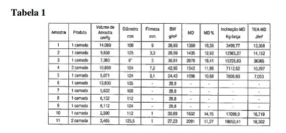

[00140] Deve ser entendido que a invenção inclui várias modificações que podem ser realizadas em relação às modalidades exemplificativas do rebobinador/bobinador de centro/de superfície descritas aqui como recaindo dentro do escopo das reivindicações anexas e seus equivalentes. Além disso, deve ser entendido que o termo "bobinador", conforme usado nas reivindicações, é amplo o suficiente para englobar tanto um bobinador quanto um rebobinador.[00140] It is to be understood that the invention includes various modifications that may be made with respect to the exemplary embodiments of the center/surface rewinder/winder described herein as falling within the scope of the appended claims and their equivalents. Furthermore, it is to be understood that the term "winder" as used in the claims is broad enough to encompass both a winder and a winder.
Claims (10)
Applications Claiming Priority (3)
| Application Number | Priority Date | Filing Date | Title |
|---|---|---|---|
| US12/750,380 US8757533B2 (en) | 2002-02-28 | 2010-03-30 | Center/surface rewinder and winder |
| US12/750,380 | 2010-03-30 | ||
| PCT/IB2011/050707 WO2011121460A2 (en) | 2010-03-30 | 2011-02-21 | Center/surface rewinder and winder |
Publications (2)
| Publication Number | Publication Date |
|---|---|
| BR112012024974A2 BR112012024974A2 (en) | 2020-09-01 |
| BR112012024974B1 true BR112012024974B1 (en) | 2021-04-20 |
Family
ID=44712690
Family Applications (1)
| Application Number | Title | Priority Date | Filing Date |
|---|---|---|---|
| BR112012024974-6A BR112012024974B1 (en) | 2010-03-30 | 2011-02-21 | process for unwinding a mother roll to form multiple product rolls |
Country Status (4)
| Country | Link |
|---|---|
| US (1) | US8757533B2 (en) |
| EP (1) | EP2552816B1 (en) |
| BR (1) | BR112012024974B1 (en) |
| WO (1) | WO2011121460A2 (en) |
Families Citing this family (12)
| Publication number | Priority date | Publication date | Assignee | Title |
|---|---|---|---|---|
| US9925734B2 (en) * | 2011-04-20 | 2018-03-27 | Cmd Corporation | Method and apparatus for making bags |
| US9016612B2 (en) | 2011-09-20 | 2015-04-28 | Kimberly-Clark Worldwide, Inc. | Simultaneous winding of tissue webs |
| US8910897B2 (en) * | 2012-08-07 | 2014-12-16 | The Procter & Gamble Company | Web rewinding apparatus |
| US9045303B2 (en) | 2012-08-07 | 2015-06-02 | The Procter & Gamble Company | Mandrel cupping assembly |
| US8915461B2 (en) * | 2012-08-07 | 2014-12-23 | The Procter & Gamble Company | Mandrel cupping assembly |
| US9027870B2 (en) | 2012-08-07 | 2015-05-12 | The Procter & Gamble Company | Web rewinding apparatus |
| US11921112B2 (en) | 2014-12-18 | 2024-03-05 | Paragraf Usa Inc. | Chemically-sensitive field effect transistors, systems, and methods for manufacturing and using the same |
| US10239726B2 (en) | 2016-06-15 | 2019-03-26 | Dynamex Corporation | Ribbon self-orienting device for traversed rolls |
| WO2022211792A1 (en) * | 2021-03-30 | 2022-10-06 | Kimberly-Clark Worldwide, Inc. | System and method for building a roll of material |
| IT202200014710A1 (en) * | 2022-07-13 | 2024-01-13 | Ims Tech S P A | CONVERTING MACHINE WITH AUTOMATIC THREADING OF THE MATERIAL TAPE |
| IT202200014725A1 (en) * | 2022-07-13 | 2024-01-13 | Ims Tech S P A | CONVERTING MACHINE WITH MATERIAL TAPE ACCUMULATION WAREHOUSE |
| CN117682361B (en) * | 2024-01-31 | 2024-04-23 | 珠海市鼎胜胶粘塑料环保科技有限公司 | A reeling device for processing fully degradable express bags |
Family Cites Families (100)
| Publication number | Priority date | Publication date | Assignee | Title |
|---|---|---|---|---|
| US125597A (en) * | 1872-04-09 | Thomas j | ||
| US3123315A (en) * | 1964-03-03 | Cutting sheets of web material | ||
| US28353A (en) | 1860-05-22 | Arrangement of coxtitter-shafts | ||
| US1648990A (en) * | 1927-11-15 | Assigwob to the | ||
| US1894253A (en) * | 1929-06-28 | 1933-01-10 | Pope Appliance Corp | Mechanism for winding paper into rolls |
| US2328582A (en) * | 1940-10-16 | 1943-09-07 | Standard Register Co | Strip severing and bursting machine |
| US2326173A (en) * | 1941-10-18 | 1943-08-10 | Sylvania Ind Corp | Process and apparatus for handling material |
| US2913098A (en) * | 1957-01-02 | 1959-11-17 | Western Gear Corp | Core-loader for winding machine |
| US2979278A (en) * | 1959-06-16 | 1961-04-11 | Elastic Fabric Co Inc | Textile machines |
| US3148843A (en) * | 1959-10-09 | 1964-09-15 | Fmc Corp | Breaker bar for web rewinding machine |
| NL278449A (en) * | 1961-05-15 | |||
| US3179348A (en) * | 1962-09-17 | 1965-04-20 | Paper Converting Machine Co | Web-winding apparatus and method |
| US3315908A (en) * | 1965-05-03 | 1967-04-25 | Means & Co F W | Winding apparatus |
| US3430881A (en) * | 1967-06-23 | 1969-03-04 | Ruesch Ferd Maschf | Automatic apparatus for continuously winding strip material |
| CH476620A (en) | 1967-12-22 | 1969-08-15 | Reifenhaeuser Kg | Winding machine for winding up continuously produced webs of material |
| US3519214A (en) * | 1968-11-25 | 1970-07-07 | Alexander Konrad | Apparatus for rolling fabric bandages |
| US3733035A (en) * | 1971-03-10 | 1973-05-15 | C Schott | Winder |
| US3869095A (en) * | 1973-10-23 | 1975-03-04 | Beloit Corp | Three drum winder |
| US4034928A (en) * | 1976-06-29 | 1977-07-12 | Union Carbide Corporation | Method and apparatus for producing coreless roll assemblies of separable bags |
| US4103840A (en) * | 1976-12-14 | 1978-08-01 | Westvaco Corporation | Stretchable material rewinding machine |
| US4087319A (en) * | 1976-12-27 | 1978-05-02 | Beloit Corporation | Method of and means for sheet transfer to and embossing at a reeling station |
| IT1081729B (en) * | 1977-05-04 | 1985-05-21 | Ind Veneta Gomma Colbachini I | METHOD AND DEVICE FOR THE PACKAGING, IN REELS, OF RUBBER TAPES OR OTHERWISE IN EXTENSIBLE POWDER, IN PARTICULAR FOR THE PRODUCTION OF RUBBER TUBES |
| AT355417B (en) * | 1977-04-26 | 1980-03-10 | Escher Wyss Gmbh | WINDING DEVICE FOR PAPER MACHINES |
| AT363321B (en) * | 1978-03-22 | 1981-07-27 | Escher Wyss Gmbh | WINDING DEVICE FOR PAPER MACHINES |
| US4191341A (en) * | 1979-04-03 | 1980-03-04 | Gottlieb Looser | Winding apparatus and method |
| US4327876A (en) * | 1980-10-02 | 1982-05-04 | William T. Kuhn | Continuous center-winding apparatus and method |
| US4398678A (en) * | 1981-04-29 | 1983-08-16 | Eastman Kodak Company | Variable-width web slitting and winding apparatus |
| CA1201055A (en) | 1983-02-04 | 1986-02-25 | Louis J. Bagnato | Cut off knife |
| DE3308271A1 (en) * | 1983-03-09 | 1984-09-20 | Jagenberg AG, 4000 Düsseldorf | DEVICE FOR REWINDING LENGTH-SIDED SHEETS AND METHOD FOR WINDING REELS / CASE CHANGE |
| IT1171233B (en) * | 1983-09-27 | 1987-06-10 | Mira Lanza Spa | WINDING MACHINE FOR WRAPPING PAPER TAPES ON CARDBOARD CORES OR SIMILAR |
| US4529141A (en) * | 1984-01-13 | 1985-07-16 | Imd Corporation | Method and apparatus for rewinding, severing and transferring web-like material |
| US4588138A (en) * | 1984-06-29 | 1986-05-13 | Paper Converting Machine Company | Web winding machine |
| US4541583A (en) * | 1985-01-09 | 1985-09-17 | Mobil Oil Corporation | Continuous layon roller film winder |
| US4723724A (en) * | 1985-04-17 | 1988-02-09 | Paper Converting Machine | Web winding machine and method |
| US4856725A (en) * | 1986-04-01 | 1989-08-15 | Paper Converting Machine Company | Web winding machine and method |
| US4962897A (en) * | 1986-04-01 | 1990-10-16 | Paper Converting Machine Company | Web winding machine and method |
| DE3629024C3 (en) * | 1986-08-27 | 1994-09-01 | Jagenberg Ag | Device for inserting a winding tube into a winding machine |
| DE3736395A1 (en) | 1987-10-28 | 1989-05-11 | Werner Muelfarth | DEVICE FOR UNWINDING OR ROLLING UP RAIL OR BAND-SHAPED MATERIALS |
| DE3836195A1 (en) * | 1988-10-24 | 1990-04-26 | Windmoeller & Hoelscher | DEVICE FOR WINDING MATERIAL COATS ON WRAPPING SLEEVES |
| US4930711A (en) * | 1989-01-17 | 1990-06-05 | Krantz America, Inc. | Automatic defect cutting assembly for a continuous fabric winder |
| DE3903270C2 (en) * | 1989-02-03 | 1995-03-23 | Windmoeller & Hoelscher | Device for sliding several winding cores onto spreadable shafts in the correct position |
| DE3920659A1 (en) | 1989-05-31 | 1991-01-10 | Iro Calator Ab | Cloth inspection table |
| IT1233708B (en) | 1989-07-11 | 1992-04-14 | Perini Navi Spa | REWINDING MACHINE FOR THE FORMATION OF ROLLS OR STICKS, AND WINDING METHOD |
| FR2669013A1 (en) | 1990-11-08 | 1992-05-15 | Achard Picard Jean | Improvements made to friction shafts for driving reels (bobbins) |
| DE4104635B4 (en) * | 1991-02-15 | 2005-11-10 | Mülfarth, Werner | Device for rolling up web or strip-shaped materials |
| US5346150A (en) * | 1992-01-21 | 1994-09-13 | Minnesota Mining And Manufacturing Company | Tail gap winder |
| WO1993021094A1 (en) * | 1992-04-15 | 1993-10-28 | Yugen Kaisha Kaji Seisakusho | Method for producing roll of core-less toilet paper and roll of core-less toilet paper produced by the same method |
| EP0589481B1 (en) * | 1992-09-25 | 1999-06-09 | Tokushichi Yamazaki | Method of forming a coreless roll of web material |
| DE9216261U1 (en) * | 1992-10-19 | 1994-02-24 | Windmöller & Hölscher, 49525 Lengerich | Device for winding a web |
| JP3271807B2 (en) * | 1992-12-28 | 2002-04-08 | 日本テトラパック株式会社 | Film splicer |
| US5505402A (en) | 1993-02-18 | 1996-04-09 | Paper Converting Machine Company | Coreless surface winder and method |
| US5402960A (en) * | 1993-08-16 | 1995-04-04 | Paper Converting Machine Company | Coreless surface winder and method |
| IT1262046B (en) * | 1993-03-24 | 1996-06-18 | Guglielmo Biagiotti | REWINDING MACHINE FOR THE FORMATION OF ROLLS OF TAPE MATERIAL WITH MEANS FOR THE INTERRUPTION OF THE TAPE MATERIAL AND RELATIVE WINDING METHOD. |
| US5497959A (en) * | 1993-03-26 | 1996-03-12 | Paper Converting Machine Company | Coreless winding method and apparatus |
| US5421536A (en) * | 1993-07-19 | 1995-06-06 | Paper Coverting Machine Company | Surface winder with recycled mandrels and method |
| US5379964A (en) * | 1993-08-10 | 1995-01-10 | Addax, Inc. | Composite expandable shaft |
| US5474248A (en) * | 1993-08-16 | 1995-12-12 | Product Search, Inc. | Slitter/rewinder machine |
| FI94231C (en) * | 1993-12-16 | 1995-08-10 | Valmet Paper Machinery Inc | Method and apparatus for winding a web of paper or paperboard in a pope winder or the like |
| US5832696A (en) * | 1994-09-21 | 1998-11-10 | Owens Corning Fiberglas Technology, Inc. | Method and apparatus for packaging compressible insulation material |
| US5593545A (en) * | 1995-02-06 | 1997-01-14 | Kimberly-Clark Corporation | Method for making uncreped throughdried tissue products without an open draw |
| FR2732042B1 (en) * | 1995-03-22 | 1997-06-13 | Thibeau & Cie Sa A | SUCTION CYLINDER ALLOWS THE TRANSFER OF A FIBROUS VEIL BETWEEN A CONVEYOR BELT AND TWO CALENDER CYLINDERS |
| CA2177507C (en) * | 1995-06-02 | 2001-02-13 | Kevin Benson Mcneil | Web winding apparatus |
| IT1278698B1 (en) * | 1995-06-07 | 1997-11-27 | Celli Spa | LIGHT TAPE WRAPPING EQUIPMENT |
| US5979729A (en) | 1996-03-11 | 1999-11-09 | Cmd Corporation | Separating a web at a line of weakness |
| JPH10139226A (en) * | 1996-11-12 | 1998-05-26 | Akira Shimizu | Manufacture of coreless toilet paper roll and coreless toilet paper roll |
| FR2757141B1 (en) * | 1996-12-12 | 1999-03-26 | Darlet Marchante Tech Sa | CONTINUOUS FLAT ELEMENT WINDING MACHINE FOR FORMING COILS |
| DE19704555A1 (en) * | 1997-02-06 | 1998-08-13 | Windmoeller & Hoelscher | Device for winding web material |
| FI106248B (en) * | 1997-02-13 | 2000-12-29 | Valmet Corp | Rolling machine and method of rolling up paper web or equivalent |
| US6264132B1 (en) * | 1997-05-16 | 2001-07-24 | Koenig & Bauer Aktiengesellschaft | Method and device for grasping part of an outer layer of a strip of material on a supply roll |
| WO1998055384A1 (en) | 1997-06-02 | 1998-12-10 | Beloit Technologies, Inc. | Method and apparatus for reeling a traveling paper web |
| US5944273A (en) * | 1997-07-03 | 1999-08-31 | Kimberly-Clark Worldwide, Inc. | Parent roll for tissue paper |
| US5901918A (en) * | 1997-07-03 | 1999-05-11 | Valmet-Karlstad Ab | Apparatus and method for winding paper |
| US5839688A (en) * | 1997-08-08 | 1998-11-24 | Paper Converting Machine Co. | Method and apparatus for producing a roll of bathroom tissue or kitchen toweling with a pattern being repeated between each pair of transverse perforations |
| US6047916A (en) * | 1998-03-16 | 2000-04-11 | Valmet-Karlstad Ab | Reel-up and multi-functional handling device therefor |
| US6077590A (en) * | 1998-04-15 | 2000-06-20 | Kimberly-Clark Worldwide, Inc. | High bulk paper towels |
| DE19819276A1 (en) * | 1998-04-30 | 1999-11-04 | Hoechst Trespaphan Gmbh | Process for regulating the winding density of film rolls |
| EP0994054B1 (en) * | 1998-10-14 | 2003-09-03 | Fuji Photo Film Co., Ltd. | Web processing system |
| DE19848816A1 (en) * | 1998-10-22 | 2000-04-27 | Voith Sulzer Papiertech Patent | Winding machine |
| DE19848815A1 (en) * | 1998-10-22 | 2000-04-27 | Voith Sulzer Papiertech Patent | Winding machine |
| US6056229A (en) * | 1998-12-03 | 2000-05-02 | Paper Converting Machine Co. | Surface winder with pinch cutoff |
| US6062507A (en) * | 1999-01-29 | 2000-05-16 | Alexander Machinery, Inc. | Vertical winder and method |
| US6308909B1 (en) * | 1999-02-09 | 2001-10-30 | The Procter & Gamble Company | Web rewinder chop-off and transfer assembly |
| FI990956A0 (en) | 1999-04-28 | 1999-04-28 | Valmet Corp | Procedure for continuous rewinding of a paper web and wheelchair |
| IT1307874B1 (en) * | 1999-05-11 | 2001-11-19 | Perini Fabio Spa | METHOD AND DEVICE FOR THE PRODUCTION OF ROLLS OF STRUCTURAL MATERIALS WITHOUT A WRAPPING CORE. |
| US6220541B1 (en) * | 1999-06-03 | 2001-04-24 | Ctc International Inc. | Web winding apparatus with two mandrels mounted at fixed positions and knife carriage movable therebetween |
| US6283402B1 (en) * | 1999-06-17 | 2001-09-04 | Ashe Controls, Ltd. | Rewinder method and apparatus |
| US6270629B1 (en) | 1999-08-13 | 2001-08-07 | Voith Sulzer Papertechnik Patent Gmbh | Web handling apparatus |
| JP3260343B2 (en) * | 1999-09-08 | 2002-02-25 | 日本圧着端子製造株式会社 | Pin header and manufacturing method thereof |
| TW482174U (en) * | 2000-12-14 | 2002-04-01 | Defence Dept Chung Shan Inst | Movable conveying belt machine |
| EP1326794B1 (en) | 2001-01-16 | 2006-02-01 | FABIO PERINI S.p.A. | Rewinding machine to rewind web material on a core for rolls and corresponding method of winding |
| US6709549B2 (en) * | 2001-03-29 | 2004-03-23 | Metso Paper Karlstad Ab | Multi-reel apparatus in a paper machine |
| ITMI20010306U1 (en) | 2001-06-01 | 2002-12-02 | Gambini Giovanni | DEVICE FOR REWINDING AND FORMING A CARTAIN ROLL A REWINDING MACHINE |
| US6729572B2 (en) * | 2001-10-31 | 2004-05-04 | Kimberly-Clark Worldwide, Inc. | Mandrelless center/surface rewinder and winder |
| US8210462B2 (en) | 2002-02-28 | 2012-07-03 | Kimberly-Clark Worldwide, Inc. | Center/surface rewinder and winder |
| US8042761B2 (en) | 2002-02-28 | 2011-10-25 | Kimberly-Clark Worldwide, Inc. | Center/surface rewinder and winder |
| US7909282B2 (en) * | 2002-02-28 | 2011-03-22 | Kimberly-Clark Worldwide, Inc. | Center/surface rewinder and winder |
| US7000864B2 (en) * | 2002-06-10 | 2006-02-21 | The Procter & Gamble Company | Consumer product winding control and adjustment |
| US7175127B2 (en) * | 2002-09-27 | 2007-02-13 | C.G. Bretting Manufacturing Company, Inc. | Rewinder apparatus and method |
| US6877689B2 (en) * | 2002-09-27 | 2005-04-12 | C.G. Bretting Mfg. Co., Inc. | Rewinder apparatus and method |
| US7874509B2 (en) * | 2006-04-12 | 2011-01-25 | Kenney James W | Automated dispenser |
-
2010
- 2010-03-30 US US12/750,380 patent/US8757533B2/en not_active Expired - Lifetime
-
2011
- 2011-02-21 WO PCT/IB2011/050707 patent/WO2011121460A2/en not_active Ceased
- 2011-02-21 BR BR112012024974-6A patent/BR112012024974B1/en active IP Right Grant
- 2011-02-21 EP EP11762091.4A patent/EP2552816B1/en active Active
Also Published As
| Publication number | Publication date |
|---|---|
| US8757533B2 (en) | 2014-06-24 |
| US20110057068A1 (en) | 2011-03-10 |
| BR112012024974A2 (en) | 2020-09-01 |
| EP2552816A2 (en) | 2013-02-06 |
| WO2011121460A2 (en) | 2011-10-06 |
| EP2552816B1 (en) | 2021-04-07 |
| EP2552816A4 (en) | 2016-03-02 |
| WO2011121460A3 (en) | 2012-02-23 |
Similar Documents
| Publication | Publication Date | Title |
|---|---|---|
| BR112012024974B1 (en) | process for unwinding a mother roll to form multiple product rolls | |
| CA2681863C (en) | Apparatus and method for breaking a web | |
| US8459587B2 (en) | Center/surface rewinder and winder | |
| US8210462B2 (en) | Center/surface rewinder and winder | |
| JP5933564B2 (en) | Winder and method for producing rolls of web material | |
| KR20010110431A (en) | Web rewinder chop-off and transfer assembly | |
| CN109573680A (en) | For cutting cork paper twinax high-speed cutting machine | |
| CN110371739B (en) | Full-automatic feeding method | |
| CN209583139U (en) | For cutting cork paper twinax high-speed cutting machine | |
| BR112014000967B1 (en) | method of breaking a moving coil, and, coil cutting system | |
| AU2008243899B2 (en) | Apparatus and method for breaking a web | |
| US10315874B2 (en) | Short strain cutoff device | |
| CN111196518A (en) | A roll film forming device for automatic packaging machine | |
| CN120646584A (en) | Reel changer and reel change control method |
Legal Events
| Date | Code | Title | Description |
|---|---|---|---|
| B06U | Preliminary requirement: requests with searches performed by other patent offices: procedure suspended [chapter 6.21 patent gazette] | ||
| B09A | Decision: intention to grant [chapter 9.1 patent gazette] | ||
| B16A | Patent or certificate of addition of invention granted [chapter 16.1 patent gazette] |
Free format text: PRAZO DE VALIDADE: 10 (DEZ) ANOS CONTADOS A PARTIR DE 20/04/2021, OBSERVADAS AS CONDICOES LEGAIS. |
|
| B25A | Requested transfer of rights approved |
Owner name: KIMBERLY-CLARK EDE HOLDINGS B.V. (PB) |
|
| B25A | Requested transfer of rights approved |
Owner name: KIMBERLY-CLARK BRASIL INDUSTRIA E COMERCIO DE PRODUTOS DE HIGIENE LTDA. (BR/SP) |
|
| B25A | Requested transfer of rights approved |
Owner name: MMC BRASIL INDUSTRIA E COMERCIO LTDA. (BR/SP) |