BRPI0213151B1 - SELF-TITRATION PRESSURE SUPPORT SYSTEM - Google Patents
SELF-TITRATION PRESSURE SUPPORT SYSTEM Download PDFInfo
- Publication number
- BRPI0213151B1 BRPI0213151B1 BRPI0213151-0A BRPI0213151A BRPI0213151B1 BR PI0213151 B1 BRPI0213151 B1 BR PI0213151B1 BR PI0213151 A BRPI0213151 A BR PI0213151A BR PI0213151 B1 BRPI0213151 B1 BR PI0213151B1
- Authority
- BR
- Brazil
- Prior art keywords
- pressure
- patient
- control layer
- control
- flow
- Prior art date
Links
- 238000004448 titration Methods 0.000 title abstract description 14
- 230000029058 respiratory gaseous exchange Effects 0.000 claims abstract description 84
- 238000000034 method Methods 0.000 claims abstract description 68
- 230000008569 process Effects 0.000 claims abstract description 33
- 206010021079 Hypopnoea Diseases 0.000 claims description 185
- 208000008784 apnea Diseases 0.000 claims description 127
- 206010041235 Snoring Diseases 0.000 claims description 91
- 238000001514 detection method Methods 0.000 claims description 90
- 238000012544 monitoring process Methods 0.000 claims description 72
- 238000006073 displacement reaction Methods 0.000 claims description 35
- 230000007423 decrease Effects 0.000 claims description 32
- 230000008859 change Effects 0.000 claims description 22
- 230000000241 respiratory effect Effects 0.000 claims description 15
- 230000004913 activation Effects 0.000 claims description 10
- 230000003434 inspiratory effect Effects 0.000 abstract description 81
- 238000004458 analytical method Methods 0.000 abstract description 35
- 239000007789 gas Substances 0.000 description 39
- 208000003417 Central Sleep Apnea Diseases 0.000 description 29
- 230000000414 obstructive effect Effects 0.000 description 29
- 230000007774 longterm Effects 0.000 description 17
- 238000012423 maintenance Methods 0.000 description 15
- 230000014759 maintenance of location Effects 0.000 description 12
- 238000004364 calculation method Methods 0.000 description 11
- 238000005259 measurement Methods 0.000 description 11
- 238000001994 activation Methods 0.000 description 10
- 238000007796 conventional method Methods 0.000 description 10
- 230000006870 function Effects 0.000 description 10
- 230000004044 response Effects 0.000 description 10
- 230000033001 locomotion Effects 0.000 description 7
- 230000007958 sleep Effects 0.000 description 7
- 239000003570 air Substances 0.000 description 6
- QVGXLLKOCUKJST-UHFFFAOYSA-N atomic oxygen Chemical compound [O] QVGXLLKOCUKJST-UHFFFAOYSA-N 0.000 description 6
- 229910052760 oxygen Inorganic materials 0.000 description 6
- 239000001301 oxygen Substances 0.000 description 6
- 208000000884 Airway Obstruction Diseases 0.000 description 5
- 230000015556 catabolic process Effects 0.000 description 5
- 230000003247 decreasing effect Effects 0.000 description 5
- 238000006731 degradation reaction Methods 0.000 description 5
- 238000010606 normalization Methods 0.000 description 5
- 208000001797 obstructive sleep apnea Diseases 0.000 description 5
- 230000002829 reductive effect Effects 0.000 description 5
- 238000002560 therapeutic procedure Methods 0.000 description 5
- 238000013459 approach Methods 0.000 description 4
- 230000000903 blocking effect Effects 0.000 description 4
- 239000006185 dispersion Substances 0.000 description 4
- 230000006872 improvement Effects 0.000 description 4
- 238000012545 processing Methods 0.000 description 4
- 238000011084 recovery Methods 0.000 description 4
- 206010063968 Upper airway resistance syndrome Diseases 0.000 description 3
- 230000000593 degrading effect Effects 0.000 description 3
- 238000010586 diagram Methods 0.000 description 3
- 208000037265 diseases, disorders, signs and symptoms Diseases 0.000 description 3
- 208000035475 disorder Diseases 0.000 description 3
- 238000001595 flow curve Methods 0.000 description 3
- 230000000670 limiting effect Effects 0.000 description 3
- 238000007619 statistical method Methods 0.000 description 3
- CURLTUGMZLYLDI-UHFFFAOYSA-N Carbon dioxide Chemical compound O=C=O CURLTUGMZLYLDI-UHFFFAOYSA-N 0.000 description 2
- 230000002159 abnormal effect Effects 0.000 description 2
- 230000009471 action Effects 0.000 description 2
- 238000004422 calculation algorithm Methods 0.000 description 2
- 238000004891 communication Methods 0.000 description 2
- 239000000203 mixture Substances 0.000 description 2
- 230000036961 partial effect Effects 0.000 description 2
- 230000008667 sleep stage Effects 0.000 description 2
- 238000011144 upstream manufacturing Methods 0.000 description 2
- 206010007559 Cardiac failure congestive Diseases 0.000 description 1
- 208000007590 Disorders of Excessive Somnolence Diseases 0.000 description 1
- 206010013975 Dyspnoeas Diseases 0.000 description 1
- 206010019280 Heart failures Diseases 0.000 description 1
- 206010020772 Hypertension Diseases 0.000 description 1
- 108010064719 Oxyhemoglobins Proteins 0.000 description 1
- 208000008166 Right Ventricular Dysfunction Diseases 0.000 description 1
- 208000010340 Sleep Deprivation Diseases 0.000 description 1
- 208000013738 Sleep Initiation and Maintenance disease Diseases 0.000 description 1
- 206010041349 Somnolence Diseases 0.000 description 1
- 238000009825 accumulation Methods 0.000 description 1
- 230000003213 activating effect Effects 0.000 description 1
- 230000002411 adverse Effects 0.000 description 1
- 230000004075 alteration Effects 0.000 description 1
- 239000012080 ambient air Substances 0.000 description 1
- 206010003119 arrhythmia Diseases 0.000 description 1
- 230000001580 bacterial effect Effects 0.000 description 1
- 230000006399 behavior Effects 0.000 description 1
- 230000009286 beneficial effect Effects 0.000 description 1
- 229910002092 carbon dioxide Inorganic materials 0.000 description 1
- 239000001569 carbon dioxide Substances 0.000 description 1
- 230000001269 cardiogenic effect Effects 0.000 description 1
- 208000010877 cognitive disease Diseases 0.000 description 1
- 238000013480 data collection Methods 0.000 description 1
- 230000001934 delay Effects 0.000 description 1
- 230000001419 dependent effect Effects 0.000 description 1
- 230000009429 distress Effects 0.000 description 1
- 230000000694 effects Effects 0.000 description 1
- 238000005429 filling process Methods 0.000 description 1
- 239000012530 fluid Substances 0.000 description 1
- 230000002401 inhibitory effect Effects 0.000 description 1
- 230000000977 initiatory effect Effects 0.000 description 1
- 206010022437 insomnia Diseases 0.000 description 1
- 230000004807 localization Effects 0.000 description 1
- 210000004072 lung Anatomy 0.000 description 1
- 238000004519 manufacturing process Methods 0.000 description 1
- 238000012986 modification Methods 0.000 description 1
- 230000004048 modification Effects 0.000 description 1
- 210000003205 muscle Anatomy 0.000 description 1
- 210000003800 pharynx Anatomy 0.000 description 1
- 238000012913 prioritisation Methods 0.000 description 1
- 210000001147 pulmonary artery Anatomy 0.000 description 1
- 230000036385 rapid eye movement (rem) sleep Effects 0.000 description 1
- 230000009467 reduction Effects 0.000 description 1
- 230000019254 respiratory burst Effects 0.000 description 1
- 230000001020 rhythmical effect Effects 0.000 description 1
- 230000006814 right ventricular dysfunction Effects 0.000 description 1
- 230000035945 sensitivity Effects 0.000 description 1
- 201000002859 sleep apnea Diseases 0.000 description 1
- 238000003860 storage Methods 0.000 description 1
- 208000024891 symptom Diseases 0.000 description 1
- 230000026676 system process Effects 0.000 description 1
- 238000012360 testing method Methods 0.000 description 1
- 230000001225 therapeutic effect Effects 0.000 description 1
- 210000001519 tissue Anatomy 0.000 description 1
- 210000003437 trachea Anatomy 0.000 description 1
- 238000002627 tracheal intubation Methods 0.000 description 1
- 230000001052 transient effect Effects 0.000 description 1
- 238000009423 ventilation Methods 0.000 description 1
- 230000002618 waking effect Effects 0.000 description 1
Images


Classifications
-
- A—HUMAN NECESSITIES
- A61—MEDICAL OR VETERINARY SCIENCE; HYGIENE
- A61M—DEVICES FOR INTRODUCING MEDIA INTO, OR ONTO, THE BODY; DEVICES FOR TRANSDUCING BODY MEDIA OR FOR TAKING MEDIA FROM THE BODY; DEVICES FOR PRODUCING OR ENDING SLEEP OR STUPOR
- A61M16/00—Devices for influencing the respiratory system of patients by gas treatment, e.g. ventilators; Tracheal tubes
- A61M16/021—Devices for influencing the respiratory system of patients by gas treatment, e.g. ventilators; Tracheal tubes operated by electrical means
- A61M16/022—Control means therefor
- A61M16/024—Control means therefor including calculation means, e.g. using a processor
- A61M16/026—Control means therefor including calculation means, e.g. using a processor specially adapted for predicting, e.g. for determining an information representative of a flow limitation during a ventilation cycle by using a root square technique or a regression analysis
-
- A—HUMAN NECESSITIES
- A61—MEDICAL OR VETERINARY SCIENCE; HYGIENE
- A61M—DEVICES FOR INTRODUCING MEDIA INTO, OR ONTO, THE BODY; DEVICES FOR TRANSDUCING BODY MEDIA OR FOR TAKING MEDIA FROM THE BODY; DEVICES FOR PRODUCING OR ENDING SLEEP OR STUPOR
- A61M16/00—Devices for influencing the respiratory system of patients by gas treatment, e.g. ventilators; Tracheal tubes
- A61M16/0057—Pumps therefor
- A61M16/0063—Compressors
-
- A—HUMAN NECESSITIES
- A61—MEDICAL OR VETERINARY SCIENCE; HYGIENE
- A61M—DEVICES FOR INTRODUCING MEDIA INTO, OR ONTO, THE BODY; DEVICES FOR TRANSDUCING BODY MEDIA OR FOR TAKING MEDIA FROM THE BODY; DEVICES FOR PRODUCING OR ENDING SLEEP OR STUPOR
- A61M16/00—Devices for influencing the respiratory system of patients by gas treatment, e.g. ventilators; Tracheal tubes
- A61M16/0003—Accessories therefor, e.g. sensors, vibrators, negative pressure
- A61M2016/0015—Accessories therefor, e.g. sensors, vibrators, negative pressure inhalation detectors
- A61M2016/0018—Accessories therefor, e.g. sensors, vibrators, negative pressure inhalation detectors electrical
- A61M2016/0021—Accessories therefor, e.g. sensors, vibrators, negative pressure inhalation detectors electrical with a proportional output signal, e.g. from a thermistor
-
- A—HUMAN NECESSITIES
- A61—MEDICAL OR VETERINARY SCIENCE; HYGIENE
- A61M—DEVICES FOR INTRODUCING MEDIA INTO, OR ONTO, THE BODY; DEVICES FOR TRANSDUCING BODY MEDIA OR FOR TAKING MEDIA FROM THE BODY; DEVICES FOR PRODUCING OR ENDING SLEEP OR STUPOR
- A61M16/00—Devices for influencing the respiratory system of patients by gas treatment, e.g. ventilators; Tracheal tubes
- A61M16/0003—Accessories therefor, e.g. sensors, vibrators, negative pressure
- A61M2016/0027—Accessories therefor, e.g. sensors, vibrators, negative pressure pressure meter
-
- A—HUMAN NECESSITIES
- A61—MEDICAL OR VETERINARY SCIENCE; HYGIENE
- A61M—DEVICES FOR INTRODUCING MEDIA INTO, OR ONTO, THE BODY; DEVICES FOR TRANSDUCING BODY MEDIA OR FOR TAKING MEDIA FROM THE BODY; DEVICES FOR PRODUCING OR ENDING SLEEP OR STUPOR
- A61M16/00—Devices for influencing the respiratory system of patients by gas treatment, e.g. ventilators; Tracheal tubes
- A61M16/0003—Accessories therefor, e.g. sensors, vibrators, negative pressure
- A61M2016/003—Accessories therefor, e.g. sensors, vibrators, negative pressure with a flowmeter
- A61M2016/0033—Accessories therefor, e.g. sensors, vibrators, negative pressure with a flowmeter electrical
- A61M2016/0039—Accessories therefor, e.g. sensors, vibrators, negative pressure with a flowmeter electrical in the inspiratory circuit
-
- A—HUMAN NECESSITIES
- A61—MEDICAL OR VETERINARY SCIENCE; HYGIENE
- A61M—DEVICES FOR INTRODUCING MEDIA INTO, OR ONTO, THE BODY; DEVICES FOR TRANSDUCING BODY MEDIA OR FOR TAKING MEDIA FROM THE BODY; DEVICES FOR PRODUCING OR ENDING SLEEP OR STUPOR
- A61M2205/00—General characteristics of the apparatus
- A61M2205/15—Detection of leaks
-
- A—HUMAN NECESSITIES
- A61—MEDICAL OR VETERINARY SCIENCE; HYGIENE
- A61M—DEVICES FOR INTRODUCING MEDIA INTO, OR ONTO, THE BODY; DEVICES FOR TRANSDUCING BODY MEDIA OR FOR TAKING MEDIA FROM THE BODY; DEVICES FOR PRODUCING OR ENDING SLEEP OR STUPOR
- A61M2205/00—General characteristics of the apparatus
- A61M2205/50—General characteristics of the apparatus with microprocessors or computers
Landscapes
- Health & Medical Sciences (AREA)
- Life Sciences & Earth Sciences (AREA)
- General Health & Medical Sciences (AREA)
- Engineering & Computer Science (AREA)
- Anesthesiology (AREA)
- Biomedical Technology (AREA)
- Heart & Thoracic Surgery (AREA)
- Pulmonology (AREA)
- Hematology (AREA)
- Animal Behavior & Ethology (AREA)
- Emergency Medicine (AREA)
- Public Health (AREA)
- Veterinary Medicine (AREA)
- Measurement Of The Respiration, Hearing Ability, Form, And Blood Characteristics Of Living Organisms (AREA)
- Nitrogen Condensed Heterocyclic Rings (AREA)
- Investigating Or Analysing Biological Materials (AREA)
- Control Of Fluid Pressure (AREA)
Abstract
"SISTEMA DE SUPORTE DE PRESSAO DE AUTO-TITULAQAO E METODO DE USAR O MESMO". Um sistema de suporte de pressao (30) e metodo de tratar respiragSo desordenada que otimiza a pressao fomecida ao paciente para tratar a respiragao desordenada enquanto minimiza a pressao fomecida para conforto do paciente. O controlador (50) no sistema de suporte de pressao opera como um conjunto de camadas de controle priorizado, em que cada camada de controle compete pelo controle do sistema de geragao de pressao (32) para implementar um processo de controle de pressao exclusivo. O sistema de suporte de pressao tambem controla a pressao fomecida ao paciente com base na variabilidade dos dados monitorados e uma an&lise de tendencia desses dados, incluindo uma indicagSo da assimetria da forma de onda inspiratdria do paciente."SELF-TITRATION PRESSURE SUPPORT SYSTEM AND METHOD OF USING THE SAME". A pressure support system (30) and method of treating disordered breathing that optimizes the pressure delivered to the patient to treat disordered breathing while minimizing the pressure delivered for patient comfort. The controller (50) in the pressure support system operates as a set of prioritized control layers, with each control layer competing for control of the pressure generation system (32) to implement a unique pressure control process. The pressure support system also controls the pressure delivered to the patient based on the variability of the monitored data and a trend analysis of that data, including an indication of the asymmetry of the patient's inspiratory waveform.
Description
O presente pedido reivindica a prioridade de acordo com 35 U.S.C. § 119(e) do pedido de patente provisoria norte-americana numero 60/329.250 depositado em 12 de outubro de 2001 e pedido de patente provisoria norte-americana numero 60/331.838 depositado em 20 de novembro de 2001, cujos teores sao aqui incorporados a titulo de referenda.The present application claims priority under 35 USC § 119 (e) of US provisional patent application number 60 / 329,250 filed on October 12, 2001 and US provisional patent application number 60 / 331,838 filed on 20 November 2001, the contents of which are hereby incorporated by reference.
A presente invengao refere-se a urn sistema de suporte de pressao e metodo de tratamento de respiragao desordenada e, em particular, a urn sistema de suporte de pressao de auto-titulagao e a urn metodo de automaticamente titular urn sistema de suporte de pressao para otimizar a pressao fornecida ao paciente a firn de tratar a respiragao desordenada enquanto minimiza de outro modo a pressao fornecida para conforto do paciente.The present invention relates to a pressure support system and a disorderly breathing treatment method and, in particular, a self-titration pressure support system and a method of automatically holding a pressure support system for optimizing the pressure provided to the patient in order to treat disordered breathing while otherwise minimizing the pressure provided for patient comfort.
E bem sabido que muitos individuos sofrem de respiragao desordenada durante sono. Apneia obstrutiva do sono (OSA) e urn exemplo comum dessa respiragao desordenada apresentada por milhoes de pessoas em todo o mundo. OSA e uma condigao na qual o sono e repetidamente interrompido por incapacidade de respirar, o que ocorre devido a uma obstrugao das vias aereas; tipicamente a via aerea superior ou area da faringe. Acredita-se em geral que a obstrugao da via aerea seja devido, pelo menos em parte, a urn relaxamento geral dos musculos que estabilizam o segmento de via aerea superior, desse modo permitindo que os tecidos fechem a via aerea.It is well known that many individuals suffer from disordered breathing during sleep. Obstructive sleep apnea (OSA) is a common example of this disordered breathing experienced by millions of people around the world. OSA is a condition in which sleep is repeatedly interrupted due to an inability to breathe, which occurs due to an airway obstruction; typically the upper airway or pharynx area. Airway obstruction is generally believed to be due, at least in part, to a general relaxation of the muscles that stabilize the upper airway segment, thereby allowing the tissues to close the airway.
Aquelas pessoas afligidas com OSA experimentam fragmenta^ao de sono e cessaqao completa ou quase completa de ventilaqao intermitentemente durante sono com graus potencialmente severos de dessaturaqao de oxiemoglobina. Esses sintomas podem ser traduzidos clinicamente como extrema sonolencia diurna, arritmias cardiacas, hipertensao de arteria-pulmonar, insuficiencia cardiaca congestiva e/ou disfunqao cognitiva. Outras consequencias de OSA incluem disfunqao ventricular direita, retenqao de dioxido de carbono durante insonia, bem como durante sono, e tensao de oxigenio arterial reduzida continua. As pessoas que sofrem de apneia do sono podem estar em risco de mortalidade excessiva a partir desses fatores bem como por urn risco elevado de acidentes enquanto dirigem e/ou operam equipamentos potencialmente perigosos.Those people afflicted with OSA experience sleep fragmentation and complete or almost complete cessation of ventilation intermittently during sleep with potentially severe degrees of oxyhemoglobin desaturation. These symptoms can be translated clinically as extreme daytime sleepiness, cardiac arrhythmias, pulmonary artery hypertension, congestive heart failure and / or cognitive dysfunction. Other consequences of OSA include right ventricular dysfunction, retention of carbon dioxide during insomnia, as well as during sleep, and continuous reduced arterial oxygen tension. People suffering from sleep apnea may be at risk of excessive mortality from these factors as well as an increased risk of accidents while driving and / or operating potentially dangerous equipment.
Mesmo se urn paciente nao sofrer de uma obstruqao completa da via aerea, e sabido tambem que efeitos adversos, como despertar de sono, podem ocorrer onde ha apenas uma obstruqao parcial da via aerea. A obstruqao parcial da via aerea resulta tipicamente em respiraqao nao profunda mencionada como hipopneia. Outros tipos de respiraqao desordenada incluem sindrome de resistencia da via aerea superior (UARS) e vibraqao da via aerea, como vibraqao da parede da faringe, comumente mencionado como roncar. Tambem e sabido que o ronco pode acompanhar o fechamento da via aerea conduzindo a UARS, hipopneia ou apneia. Desse modo, o ronco serve como indicador de que o paciente esta experimentando respiraqao anormal.Even if a patient does not suffer from a complete airway obstruction, it is also known that adverse effects, such as waking up from sleep, can occur where there is only a partial airway obstruction. Partial airway obstruction typically results in shallow breathing referred to as hypopnea. Other types of disordered breathing include upper airway resistance syndrome (UARS) and airway vibration, such as pharyngeal wall vibration, commonly referred to as snoring. It is also known that snoring can accompany airway closure leading to UARS, hypopnea or apnea. In this way, snoring serves as an indicator that the patient is experiencing abnormal breathing.
E conhecido o tratamento dessa respiraqao desordenada pela aplicaqao de pressao de ar positive e continue (CPAP) na via aerea do paciente. Essa pressao positiva "segura" de forma eficaz a via aerea, desse modo mantendo uma passagem aberta para os pulmoes. Tambem e conhecido o fornecimento de uma terapia de pressao positiva na qual a pressao de gas fornecida ao paciente varia com o ciclo de respiraqao do paciente, ou varia com o esforqo do paciente, para aumentar o conforto para o paciente. Essa tecnica de suporte de pressao e mencionada como um suporte de pressao de dois niveis, no qual a pressao de via aerea positiva inspiratoria (IPAP) que e fornecida ao paciente e mais elevada do que a pressao de via aerea positiva expiratoria (EPAP).It is known to treat this disordered breathing by applying positive and continuous air pressure (CPAP) to the patient's airway. This positive pressure effectively "holds" the airway, thereby maintaining an open passage to the lungs. It is also known to provide positive pressure therapy in which the gas pressure delivered to the patient varies with the patient's breathing cycle, or varies with the patient's effort, to increase patient comfort. This pressure support technique is referred to as a two-level pressure support, in which the positive inspiratory airway pressure (IPAP) that is delivered to the patient is higher than the positive expiratory airway pressure (EPAP).
E adicionalmente conhecido o fornecimento de uma terapia de pressao positiva na qual uma pressao positiva e continue e fornecida ao paciente, e onde o nivel dessa pressao e automaticamente ajustado com base nas condiqoes detectadas do paciente, como se o paciente estivesse roncando ou experimentando apneia, hipopneia ou resistencia da via aerea superior. Essa tecnica de suporte de pressao e mencionada como um tipo de auto-titulaqao de suporte de pressao, porque o dispositivo de suporte de pressao procura fornecer uma pressao para o paciente que e apenas tao elevada quanto necessaria para tratar a respiraqao desordenada.It is additionally known to provide positive pressure therapy in which positive and continuous pressure is provided to the patient, and where the pressure level is automatically adjusted based on the patient's detected conditions, as if the patient is snoring or experiencing apnea, hypopnea or upper airway resistance. This pressure support technique is referred to as a type of pressure support self-titration, because the pressure support device seeks to provide pressure for the patient that is only as high as necessary to treat disordered breathing.
Os exemplos de sistemas de suporte de pressao de auto-titulaqao convencional sao descritos nas patentes US nos. 5.245.995, de Sullivan e outros; 5.259.373, 5.549.106 e 5.845.636, todas de Gruenke e outros; 5.458.137 e 6.058.747, ambas de Axe e outros; 5.704.345; 6.029.665 e 6.138.675, todas de Berthon-Jones; 5.645.053, de Reimers e outros; e 5.335.654, 5.490.502, 5.535.739 e 5.803.066, todas de Rapoport e outros. Todos esses sistemas de suporte de pressao convencionais, com a possivel exceqao da patente US no. 5.645.053 de Remmers e outros, sao reativos a condiqao monitorada do paciente. Isto e, apos ocorrer uma condipao que indica respiraqao anormal, o sistema altera o sistema de suporte de pressao para tratar essa condiqao. Os presentes inventores descobriram, contudo, que essa tecnica de trata-mento pode nao ser apropriada para todos os pacientes, e pode fazer com que o sistema reaja desnecessariamente a anomalies temporaries brandas.Examples of conventional self-titration pressure support systems are described in US patents nos. 5,245,995, by Sullivan and others; 5,259,373, 5,549,106 and 5,845,636, all by Gruenke and others; 5,458,137 and 6,058,747, both from Ax and others; 5,704,345; 6,029,665 and 6,138,675, all by Berthon-Jones; 5,645,053, by Reimers and others; and 5,335,654, 5,490,502, 5,535,739 and 5,803,066, all by Rapoport and others. All of these conventional pressure support systems, with the possible exception of US patent no. 5,645,053 by Remmers et al., Are reactive to the patient's monitored condition. That is, after a condition occurs that indicates abnormal breathing, the system changes the pressure support system to address that condition. The present inventors have found, however, that this treatment technique may not be appropriate for all patients, and may cause the system to react unnecessarily to mild temporary anomalies.
Alem disso, esses sistemas de suporte de pressao de auto-titulaqao tentam tipicamente tratar uma condiqao do paciente, como ronco ou uma limitaqao de fluxo na forma de onda inspiratoria do paciente. Acredita-se que essa abordagem de micro tratamento alvo, focalizando em uma ou duas condiqoes, nao forneqa um tratamento adequado para o paciente, que, em essencia, e um sistema muito complicado, afetado por uma pluralidade de variaveis.In addition, these self-titrating pressure support systems typically attempt to treat a patient's condition, such as snoring or a flow limitation in the patient's inspiratory waveform. It is believed that this targeted micro treatment approach, focusing on one or two conditions, does not provide adequate treatment for the patient, which, in essence, is a very complicated system, affected by a plurality of variables.
Adicionalmente, esses sistemas de auto-titulaqao convencionais apresentam diferentes abordagens para detecqao de uma condiqao do paciente. Cada abordagem tenta melhorar a capacidade de detectar condipoes do paciente que sejam verdadeiramente indicativas de um disturbio de respiraqao.In addition, these conventional self-titration systems present different approaches for detecting a patient's condition. Each approach tries to improve the ability to detect patient conditions that are truly indicative of a breathing disorder.
Contudo, acredita-se que cada abordagem seja limitada em sua capacidade de monitorar e tratar uma ampla populagao de pacientes em urn modo robusto.However, it is believed that each approach is limited in its ability to monitor and treat a wide population of patients in a robust manner.
Por conseguinte, e urn objetivo da presente invengao fornecer um sistema de suporte de pressao de autotitulagao que supere as desvantagens de sistemas de autotitulagao conveneionais. Esse objetivo e atingido de acordo com uma modalidade da presente invengao pela provisao de um sistema de suporte de pressao de auto-titulagao que inclui um sistema de geragao de pressao adaptado para gerar um fluxo de gas de respiragao em um nivel de pressao selecionavel, um circuito de paciente tendo uma primeira extremidade adaptada para ser acoplada ao sistema de geragao de pressao e uma segunda extremidade adaptada para ser acoplada a uma via aerea de um paciente, um sistema de monitoragao associado ao circuito de paciente ou sistema de geragao de pressao e adaptado para medir um parametro indicative de uma pressao na via aerea de um paciente e um fluxo de gas na via aerea do referido paciente, e transmitir um sinal de pressao e um sinal de fluxo indicative do mesmo, e um controlador acoplado ao sistema de monitoragao e ao sistema de geragao de pressao. 0 controlador controla o sistema de geragao de pressao com base na saida do sistema de monitoragao e e programado para operar de acordo com um conjunto de camadas de controle priorizadas. Cada camada de controle compete pelo controle do sistema de geragao de pressao com as outras camadas de controle e implements um processo de controle de pressao exclusive .Therefore, it is an objective of the present invention to provide a self-titration pressure support system that overcomes the disadvantages of conventional self-titration systems. This objective is achieved in accordance with an embodiment of the present invention by providing a self-titrating pressure support system that includes a pressure generation system adapted to generate a breath gas flow at a selectable pressure level, a patient circuit having a first end adapted to be coupled to the pressure generation system and a second end adapted to be coupled to a patient's airway, a monitoring system associated with the patient circuit or pressure generation system is adapted to measure a parameter indicative of a patient's airway pressure and gas flow in said patient's airway, and transmit a pressure signal and an indicative flow signal from the patient, and a controller coupled to the monitoring system and pressure generation system. The controller controls the pressure generation system based on the output of the monitoring system and is programmed to operate according to a set of prioritized control layers. Each control layer competes for the control of the pressure generation system with the other control layers and implements an exclusive pressure control process.
Em uma modalidade adicional, o controle executa uma analise de tendencia na saida do sistema de monitorapao e controls o sistema de gerapao de pressao de acordo com os resultados dessa analise de tendencia.In an additional modality, the control performs a trend analysis at the output of the monitoring system and controls the pressure generation system according to the results of this trend analysis.
Em uma modalidade ainda adicional, o controlador determine um parametro de respirapao da saida do sistema de monitorapao e analisa uma variabilidade do parametro de respirapao. 0 controlador controla entao o sistema de gerapao de pressao com base em um resultado da analise de variabilidade.In a still additional mode, the controller determines a breathing parameter for the output of the monitoring system and analyzes a variability of the breathing parameter. The controller then controls the pressure generation system based on a result of the variability analysis.
Ainda em outra modalidade, o controlador monitora vazamento de gas do circuito de paciente e reduz uma pressao fornecida a um paciente pelo sistema de gerapao de pressao por um periodo de tempo predeterminado responsive a uma determinapao de que uma taxa do vazamento de gas excede um limite predeterminado, e aumenta a pressao de volta para um nivel de pressao anterior apos decorrer o periodo de tempo predeterminado.In yet another embodiment, the controller monitors gas leakage from the patient circuit and reduces a pressure delivered to a patient by the pressure generation system for a predetermined period of time responsive to a determination that a gas leak rate exceeds a threshold. predetermined, and the pressure increases back to a previous pressure level after the predetermined period of time has elapsed.
Em outra modalidade da presente invenpao, o controlador determine uma assimetria das formas de onda inspiratorias de um paciente a partir da saida do sensor de fluxo e controla o sistema de gerapao de pressao de acordo com a determinapao de assimetria.In another embodiment of the present invention, the controller determines an asymmetry of a patient's inspiratory waveforms from the outlet of the flow sensor and controls the pressure generation system according to the determination of asymmetry.
Em uma modalidade ainda adicional da presente invenpao, o controlador determine se o paciente esta experimentando uma apneia/hipopneia central ou uma apneia/hipopneia obstrutiva/restritiva pela monitorapao de um ou mais dos seguintes: (1) pelo menos um parametro de formato associado ao fluxo de gas durante um periodo de apneia/hipopneia, e (2) uma caracteri stica do fluxo de gas no termino do periodo de apneia/hipopneia indicative de um aumento de esforpo respiratorio.In an even further embodiment of the present invention, the controller determines whether the patient is experiencing a central apnea / hypopnea or an obstructive / restrictive apnea / hypopnea by monitoring one or more of the following: (1) at least one format parameter associated with the gas flow during an apnea / hypopnea period, and (2) a characteristic of the gas flow at the end of the apnea / hypopnea period indicative of an increase in respiratory effort.
Em outra modalidade da presente invenpao, o controlador determina se o paciente esta experimentando uma apneia/hipopneia e determina se deve aumentar ou diminuir a pressao como resultado da deteepao da apneia/hipopneia com base na pressao atual em comparapao com um limite de tratamento de pressao. 0 limite de tratamento de pressao e ajustado pelo controlador com base na pressao no momento em que ocorreu a apneia/hipopneia. Essa caracteristica da presente invenpao evita que o paciente receba aumentos adicionais de pressao se aumentos anteriores de pressao nao resolveram a condipao que causou a apneia/hipopneia, que pode ser o caso se o paciente esta experimentando uma apneia/hipopneia central.In another embodiment of the present invention, the controller determines whether the patient is experiencing an apnea / hypopnea and determines whether to increase or decrease the pressure as a result of apnea / hypopnea detection based on the current pressure compared to a pressure treatment limit . The pressure treatment limit is adjusted by the controller based on the pressure at the time the apnea / hypopnea occurred. This feature of the present invention prevents the patient from receiving additional increases in pressure if previous increases in pressure have not resolved the condition that caused the apnea / hypopnea, which may be the case if the patient is experiencing central apnea / hypopnea.
E ainda outro objetivo da presente invenpao prover um metodo de fornecer um tratamento de suporte de pressao a um paciente de acordo com as funpoes operacionais do sistema de suporte de pressao discutidas acima.It is yet another object of the present invention to provide a method of providing a pressure support treatment to a patient according to the operational functions of the pressure support system discussed above.
Esses e outros objetivos, caracteristicas e aspectos da presente invenpao, bem como os metodos de operapao e funpoes dos elementos relacionados de estrutura e combinapao de partes e economia de fabricapao, tornar-se-ao mais evidentes apos considerapao da seguinte descripao e das reivindicaçoes apensas com referenda aos desenhos em anexo, todos os quais fazem parte desse relatorio descritivo, em que numerais de referenda similares designam partes correspondentes nas diversas Figuras. Deve ser expressamente entendido, contudo, que os desenhos sao para fins de ilustraqao e descriqao apenas e nao se destinam como definiqao dos limites da INVENÇÃO.These and other objectives, characteristics and aspects of the present invention, as well as the methods of operation and functions of the related elements of structure and combination of parts and economy of manufacturing, will become more evident after considering the following description and the appended claims. with reference to the attached drawings, all of which are part of that descriptive report, in which similar reference numbers designate corresponding parts in the various Figures. It should be expressly understood, however, that the drawings are for purposes of illustration and description only and are not intended to define the limits of the INVENTION.
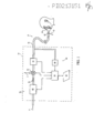
A Figura 1 e um diagrama esquematico de um sistema de suporte de pressao adaptado para operar de acordo com a tecnica de auto-titulaqao da presente INVENÇÃO;Figure 1 is a schematic diagram of a pressure support system adapted to operate according to the self-titration technique of the present INVENTION;
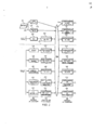
A Figura 2 e um diagrama esquematico de um sistema de controle para implementar a tecnica de auto-titulaqao da presente INVENÇÃO;Figure 2 is a schematic diagram of a control system for implementing the self-titration technique of the present INVENTION;
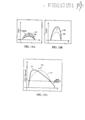
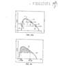
A Figura 3 e um grafico de pressao x fluxo que ilustra os criterios para determinar se deve iniciar varies aspectos de controle da tecnica de auto-titulaqao da presente INVENÇÃO;Figure 3 is a pressure x flow graph that illustrates the criteria for determining whether to initiate various aspects of controlling the self-titration technique of the present INVENTION;
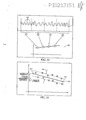
As Figuras 4A a 4C ilustram formas de onda exemplares adicionais que ilustram a diferenqa entre um pico efetivo do fluxo e um pico ponderado de fluxo QWpeak utilizado pela presente INVENÇÃO;Figures 4A to 4C illustrate additional exemplary waveforms that illustrate the difference between an effective peak flow and a weighted peak flow QWpeak used by the present INVENTION;
A Figura 5 e um grafico ilustrando uma forma de onda inspiratoria exemplar para explicar como a presente invenqao calcula varies parametros utilizados na execuqao das funqoes de auto-titulaqao;Figure 5 is a graph illustrating an exemplary inspiratory waveform to explain how the present invention calculates various parameters used in performing the self-titration functions;
A Figura 6 e um histograma exemplar dos fluxos de pico ponderados para as respiraqoes acumuladas durante o periodo de tempo de janela de movimento;Figure 6 is an exemplary histogram of the weighted peak flows for breaths accumulated during the period of time of movement window;
As Figuras 7A a 7E sao fluxogramas ilustrando o processo de detecpao de hipopneia de acordo com os principles da presente invenpao;Figures 7A to 7E are flowcharts illustrating the hypopnea detection process according to the principles of the present invention;
A Figura 8 e uma modalidade exemplar de uma forma de onda de fluxo de paciente para uso na descripao do processo de enchimento de lacuna na tecnica de detecpao de apneia da presente invenpao;Figure 8 is an exemplary embodiment of a patient flow waveform for use in describing the gap filling process in the apnea detection technique of the present invention;
A Figura 9 ilustra uma pressao de paciente exemplar para descrever a operapao do procedimento de tratamento de apneia/hipopneia do sistema de suporte de pressao;Figure 9 illustrates an exemplary patient pressure to describe the operation of the apnea / hypopnea treatment procedure of the pressure support system;
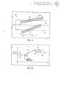
As Figuras 10A e 10B sao graficos ilustrando os exemplos da dispersao dos fluxos de pico ponderados;Figures 10A and 10B are graphs illustrating examples of dispersion of weighted peak flows;
A Figura 11 e um grafico ilustrando um processo pelo que o fluxo medio e mapeado ou normalizado de acordo com um processo de detecpao de respirapao variavel da presente invenpao;Figure 11 is a graph illustrating a process whereby the average flow is mapped or normalized according to a variable breath detection process of the present invention;
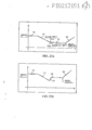
A Figura 12 e um grafico ilustrando os criterios de limite de histerese para declarar que o paciente esta experimentando respirapao variavel;Figure 12 is a graph illustrating the hysteresis limit criteria to declare that the patient is experiencing variable breathing;
A Figura 13 e um grafico ilustrando a operapao de controle de pressao do modulo de controle de respirapao variavel da presente invenpao;Figure 13 is a graph illustrating the pressure control operation of the variable breath control module of the present invention;
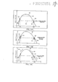
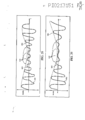
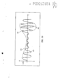
As Figuras 14A a 14C ilustram formas de onda inspiratorias de paciente exemplares para uso na explicapao dos calculos de arredondamento e achatamento da presente invenpao;Figures 14A to 14C illustrate exemplary patient inspiratory waveforms for use in explaining the rounding and flattening calculations of the present invention;
A Figura 15 ilustra uma forma de onda inspiratoria de paciente exemplar e um gabarito de onda senoidal para uso na explicapao dos calculos de arredondamento e achatamento;Figure 15 illustrates an exemplary patient inspiratory waveform and a sine wave template for use in explaining rounding and flattening calculations;
As Figuras 16A e 16B ilustram exemplos extremes de diferentes gabaritos de onda senoidal;Figures 16A and 16B illustrate extreme examples of different sine wave templates;
A Figura 17 ilustra uma curva normalizada que e utilizada para ajustar a razao dos gabaritos de onda senoidal;Figure 17 illustrates a normalized curve that is used to adjust the ratio of the sine wave templates;
As Figuras 18A e 18B ilustram gabaritos de onda senoidal mostrando como a amplitude do gabarito e corrigida de acordo com o processo de calculo de arredondamento e achatamento da presente invenpao;Figures 18A and 18B illustrate sine wave templates showing how the amplitude of the template is corrected according to the rounding and flattening calculation process of the present invention;
As Figuras 19A e 19B ilustram uma forma de onda inspiratoria de paciente exemplar e um gabarito de onda senoidal correspondente para uso na explicapao dos calculos de arredondamento e achatamento;Figures 19A and 19B illustrate an exemplary patient inspiratory waveform and a corresponding sine wave template for use in explaining rounding and flattening calculations;
A Figura 20 ilustra uma forma de onda inspiratoria de paciente mostrando como o achatamento e calculado de acordo com os principles da presente invenpao;Figure 20 illustrates a patient inspiratory waveform showing how flattening is calculated according to the principles of the present invention;
A Figura 21 ilustra uma forma de onda inspiratoria de paciente mostrando como o arredondamento e calculado de acordo com os principles da presente invenpao;Figure 21 illustrates a patient inspiratory waveform showing how rounding is calculated according to the principles of the present invention;
A Figura 22 ilustra uma forma de onda inspiratoria de paciente mostrando como a assimetria e calculada de acordo com os principios da presente invenpao;Figure 22 illustrates a patient inspiratory waveform showing how asymmetry is calculated according to the principles of the present invention;
A Figura 23 ilustra como os dados de parametro respiratorio sao acumulados para fins de analise de tendencia de acordo com os principios da presente invenpao;Figure 23 illustrates how the respiratory parameter data is accumulated for purposes of trend analysis according to the principles of the present invention;
A Figura 24 e um grafico ilustrando a tecnica de analise de tendencia da presente invenpao;Figure 24 is a graph illustrating the trend analysis technique of the present invention;
A Figura 25 e um grafico explicando o processo de votaqao realizado durante uma analise de tendencia a longo prazo de acordo com a presente INVENÇÃO;Figure 25 is a graph explaining the voting process carried out during a long-term trend analysis in accordance with the present INVENTION;
A Figura 26 ilustra uma curva de pressao exemplar transmitida pelo sistema de suporte de pressao durante uma operaqao de aumento de pressao;Figure 26 illustrates an exemplary pressure curve transmitted by the pressure support system during a pressure increase operation;
As Figuras 2 7A e 27B ilustram curvas de pressao exemplares adicionais transmitidas pelo sistema de suporte de pressao da presente INVENÇÃO;Figures 27A and 27B illustrate additional exemplary pressure curves transmitted by the pressure support system of the present INVENTION;
A Figura 2 8 ilustra uma forma de onda de fluxo de paciente exemplar durante um evento de apneia/hipopneia obstrutiva/restritiva;Figure 28 illustrates an exemplary patient flow waveform during an obstructive / restrictive apnea / hypopnea event;
A Figura 2 9 ilustra uma forma de onda de fluxo de paciente exemplar durante um evento de apneia/hipopneia central; eFigure 2 9 illustrates an exemplary patient flow waveform during a central apnea / hypopnea event; and
A Figura 3 0 ilustra uma forma de onda de fluxo de paciente exemplar adicional durante um evento de apneia/hipopneia obstrutiva/restritiva.Figure 30 illustrates an additional exemplary patient flow waveform during an obstructive / restrictive apnea / hypopnea event.
Os componentes basicos de um sistema de suporte de pressao 30 que e adaptado para implementar a tecnica de auto-titulaqao de acordo com os principios da presente invenpao sao discutidos abaixo com referenda a Figura 1. O sistema de suporte de pressao 30 inclui um sistema de geraqao de pressao, geralmente indicado em 32, e um circuito de pa-ciente 34, o qual inclui um conduto 36 e um dispositivo de interface de paciente 38. Na modalidade ilustrada, o sistema de gerapao de pressao 32 inclui um gerador de pressao 40 e uma valvula de controle de pressao 42 como a saida do gerador de pressao.The basic components of a
O gerador de pressao 40 recede o gas de respirapao de uma fonte de gas de respirapao, como indicado pela seta A, e transmite o gas de respirapao, como indicado pela seta B, para o circuito de paciente 34 em uma pressao que e superior a atmosferica para fornecimento a via aerea de um paciente (nao mostrado). Em uma modalidade preferida da presente invenpao, o gerador de pressao 40 e um gerador mecanico de pressao, como um insuflador, ventilador ou pistao, que recede ar amdiente, por exemplo, em uma entrada da fonte de gas. A valvula de controle de pressao 42 controla a pressao do fluxo de gas de respirapao fornecido ao paciente atraves do circuito de paciente limitando o fluxo para o paciente, pelo desvio do fluxo do circuito de paciente 34, como indicado pela seta C, ou uma comdinapao dos mesmos.The
A presente invenpao considera ainda o controle da pressao do fluxo de gas de respirapao fornecido ao paciente pelo controle da velocidade operacional do gerador de pressao 40, quer individualmente ou em comdinapao com a valvula 42. Evidentemente, a valvula 42 pode ser eliminada se a velocidade operacional individualmente for utilizada para controlar a pressao do fluxo de gas de respirapao fornecido ao paciente. Aqueles versados no estado da tecnica podem reconhecer que outras tecnicas para controlar a pressao do fluxo de gas de respirapao fornecido ao paciente podem ser implementadas no sistema de suporte de pressao 30, quer individualmente ou em combinagao com aquelas discutidas acima. Por exemplo, uma valvula limitadora de fluxo (nao mostrada) pode ser fomecida a montante do gerador de pressao 4 0 que controla o fluxo (seta A) de gas para o gerador de pressao 4 0 e, consequentemente, a pressao do fluxo de gas transmitido para fornecimento ao paciente.The present invention further considers the control of the pressure of the breathing gas flow provided to the patient by controlling the operating speed of the
Tipicamente, a fonte de gas de respirapao e a atmosfera ambiente, onde sua pressao e subsequentemente elevada para fornecimento ao paciente pelo sistema de gerapao de pressao. Deve ser subentendido que outras fontes de gas de respirapao sao consideradas pela presente invenpao, como oxigenio ou uma mistura de oxigenio a partir de uma fonte de oxigenio. Deve ser adicionalmente subentendido que a presente invenpao considera que o ar pressurizado pode ser fornecido a via aerea do paciente diretamente de um tanque de ar pressurizado atraves do circuito de paciente sem utilizar um gerador de pressao, com um insuflador, ventilador ou pistao, para aumentar a pressao do ar. Evidentemente, um regulador de pressao, como uma valvula 42, seria necessario para controlar a pressao do gas fornecido ao paciente. A caracteristica importante com relapao a presente invenpao e que o gas de respirapao pressurizado e fornecido no circuito de paciente para fornecimento ao paciente, nao necessariamente a fonte ou modo no qual o gas de respirapao pressurizado e gerado.Typically, the source of breathing gas is the ambient atmosphere, where its pressure is subsequently increased for delivery to the patient by the pressure generation system. It should be understood that other sources of breathing gas are considered by the present invention, such as oxygen or a mixture of oxygen from an oxygen source. It should be further understood that the present invention considers that pressurized air can be delivered to the patient's airway directly from a pressurized air tank through the patient circuit without using a pressure generator, with an insufflator, fan or piston, to increase air pressure. Of course, a pressure regulator, such as
Embora nao mostrado na Figura 1, a presente invenpao tambem considera a provisao de um fluxo de gas secundario, quer individualmente ou em combinapao com o fluxo primario de gas (seta A) da atmosfera. Por exemplo, um fluxo de oxigenio de qualquer fonte apropriada pode ser fornecido a montante para o gerador de pressao 40 ou a jusante do gerador de pressao no circuito de paciente ou no dispositivo de interface de paciente para controlar a fraqao de oxigenio inspirado fornecido ao paciente.Although not shown in Figure 1, the present invention also considers the provision of a secondary gas flow, either individually or in combination with the primary gas flow (arrow A) from the atmosphere. For example, an oxygen flow from any suitable source can be provided upstream to the
Na modalidade ilustrada, o conduto 36 no circuito de paciente 34 tern uma extremidade acoplada a safda do gerador de pressao 40 e outra extremidade acoplada ao dispositivo de interface de paciente 38. 0 conduto 36 e qualquer tube capaz de transporter o fluxo de gas do gerador de pressao ate a via aerea do paciente. Tipicamente, uma parte distal do conduto 36 em relac?ao ao gerador de pressao 4 0 e flexfvel para permitir liberdade de movimento do paciente. Deve ser entendido que varies componentes podem ser fornecidos em ou acoplados ao circuito de paciente 34. Por exemplo, um filtro de bacterias, valvula de controle de pressao, valvula de controle de fluxo, sensor, medidor, filtro de pressao, umidificador e/ou aquecedor podem ser fornecidos em ou fixados no circuito do paciente. De modo semelhante, outros componentes, como silenciosos e filtros, podem ser fornecidos na entrada do gerador de pressao 40 e na saida da valvula 42.In the illustrated embodiment, the
O dispositivo de interface de paciente 38 no circuito de paciente 34 e qualquer dispositivo apropriado para comunicar uma extremidade do conduto 3 6 com a via aerea do paciente. Os exemplos de dispositivos de interface de paciente apropriados incluem uma mascara nasal, mascara oral ou bocal, mascara nasal/oral, canula nasal, tubo da traqueia, tubo de intubaqao, capuz ou mascara completa para o rosto. Deve ser subentendido que essa lista de dispositivos de interface apropriados nao pretende ser exclusive ou exaustiva.
No circuito de paciente de membro unico da presente invenpao, o gas exalado do paciente sai tipicamente do circuito de paciente atraves de um suspiro de descarga 43, como indicado pela seta D. Na modalidade ilustrada, o suspiro de descarga 43 e fornecido em uma parte distal do conduto 34. Dependendo do volume de corrente do paciente e da pressao fornecida pelo sistema de suporte de pressao 30, uma pequena percentagem do gas exalado pode se deslocar de volta pelo conduto para dentro do sistema de suporte de pressao 30 e pode ate mesmo ser descarregado na atmosfera atraves da entrada de gas do gerador de pressao e/ou atraves de uma valvula de controle de pressao 42, se tai valvula esta sendo utilizada com o gerador de pressao.In the single member patient circuit of the present invention, the gas exhaled from the patient typically exits the patient circuit via a
Tipicamente, o suspiro de descarga 43 e um oriffcio fornecido no conduto que comunica o interior do conduto com a atmosfera, sem controle ativo sobre o fluxo de gas do sistema. Deve ser entendido, contudo, que uma ampla variedade de dispositivos e conFiguraqoes de descarga sao considerados para uso com o sistema de gerapao de pressao da presente invenpao. Por exemplo, a patente US no. 5.685.296 de Zdrojkowski e outros descreve um dispositive de exalapao e metodo onde a taxa de fluxo de exalapao atraves do dispositive permanece substancialmente constante em uma faixa de pressoes no circuito de paciente. Esse dispositive de exalapao, que e comumente mencionado como valvula de exalapao de plato ou PEV, e apropriado para uso com o sistema de suporte de pressao da presente INVENÇÃO.Typically, the
Como mostrado na Figura 1, o sistema de suporte de pressao 30 inclui um sistema de monitoragao, geralmente indicado em 44, para monitorar o fluxo e pressao de gas fornecido ao paciente. Na modalidade ilustrada, o sistema de monitoraqao 44 inclui um sensor de fluxo 46 que mede uma taxa na qual o gas de respiraqao flui dentro do circuito de paciente 34. A presente INVENÇÃO considera que qualquer sensor apropriado, como um pneumatach convencional, pode ser utilizado para sensor de fluxo 46. Deve ser adicionalmente entendido que o sensor de fluxo 46 nao necessita ser acoplado diretamente ao conduto 36. Ao contrario, a presente invenqao considera o uso de qualquer sensor ou uma pluralidade de sensores que possa medir quantitativamente o fluxo de ar no circuito de paciente. Por exemplo, o fluxo no sistema pode ser medido no dispositivo de interface de paciente ou pode ser medido ou estimado a partir do motor ou velocidade de pistao ou do torque utilizado para fornecer a pressao elevada pelo gerador de pressao 40. Em resumo, a presente invenqao considera qualquer tecnica convencional para medir o fluxo de gas fornecido ao paciente.As shown in Figure 1, the
O sistema de monitoraqao 44 tambem inclui um sensor de pressao 48 que detecta a pressao do gas no paciente. Na modalidade ilustrada, o sensor de pressao 48 esta em comunicaqao de fluido com o dispositivo de interface de paciente 38 via um conduto 36. Nessa modalidade, a pressao no paciente e calculada com base na queda de pressao conhecida que ocorre no tubo 36. Deve ser entendido, contudo, que a pressao do paciente pode ser medida diretamente no dispositive de interface de paciente 38.The
O sistema de suporte de pressao 30 inclui um controlador 50, o qual e de preferencia um microprocessador capaz de implementar um algoritmo armazenado, que recebe as variaveis monitoradas, tipicamente do sensor de fluxo 46 e do sensor de pressao 48, e controla o sistema de gerapao de pressao 32 com base nesses sinais. Evidentemente, o controlador 50 inclui a capacidade de processamento e memoria necessaria para implementar os aspectos da presente invenpao. Em uma modalidade preferida da presente invenpao, o controlador 50 e um microcontrolador AMTEL AT91M55800 que executa um software armazenado escrito na linguagem de programapao C.The
A presente invenpao considera ainda que o sistema de suporte de pressao 30 inclui uma interface de entrada/saida 52 para comunicar informapoes, dados e/ou instrupoes e quaisquer outros itens comunicaveis, coletivamente mencionados como "dados", entre um usuario e controlador 50. Os exemplos de interfaces de entrada/saida comuns apropriados para essa finalidade incluem um teclado e meio de exibipao. Outras tecnicas de comunicapao, quer com ligapao fisica ou sem fio, tambem sao consideradas pela presente invenpao. Por exemplo, a presente invenpao considera a provisao de um terminal de cartao inteligente que permite que dados sejam carregados no controlador 50 a partir do cartao inteligente ou carregados sobre o cartao inteligente a partir do controlador. Outros dispositivos de interface exemplares e tecnicas adaptados para uso com o sistema de suporte de pressao incluem, mas nao se limitam a, uma porta RS-232, leitor/gravador de CD, leitor/gravador de DVD, ligaqao RF e modem (telefone, cabo ou outro). Em resumo, qualquer tecnica convencional para fornecer, receber ou trocar dados com o controlador 50 sao considerados pela presente INVENÇÃO como dispositive de entrada/saida 52.The present invention further considers that the
O controlador 50 tambem executa tecnicas de monitoraqao de ciclo respiratorio e estimativa de vazamento convencionais. A presente INVENÇÃO considera o uso de qualquer tecnica convencional para calcular vazamento Qleak, que e o vazamento do gas do sistema de suporte de pressao e inclui vazamentos intencionais do suspiro de descarga e vazamentos nao intencionais da interface de paciente-mascara, por exem-plo. A presente INVENÇÃO tambem considera o uso de qualquer tecnica convencional para levar o vazamento em consideraqao ao se determiner o fluxo de paciente Qpatient, o qual e o fluxo de gas na via aerea do paciente, e fluxo total Qtotalr que e o fluxo de gas tipicamente medido pelo sensor de fluxo 46. Por exemplo, as patentes US nos. 5.148.802 de Sanders e outros, 5.313.937 de Zdrojkowski e outros, 5.433.193 de San-ders e outros, 5.632.269 de Zdrojkowski e outros, 5.803.065 de Zdrojkowski e outros, 6.029.664 de Zdrojkowski e outros, e 6.360.741 de Truschel, e pedidos de patente US pendentes 09/586.054 de Frank e outros e 09/970.383 de Jafari e outros, o teor de cada um e incorporado a titulo de referendana presente INVENÇÃO, todos revelam tecnicas para detectar e estimar vazamento e controlar o fornecimento de gas de respiraqao para o paciente na presenqa de vazamentos.
A presente INVENÇÃO tambem considera o uso de qualquer tecnica convencional para detectar fases inspiratoria e expiratoria do ciclo respiratorio do paciente. Por exemplo, as patentes US nos. 5.148.802 de Sanders e outros, 5.313.937 de Zdrojkowski e outros, 5.433.193 de Sanders e outros, 5.632.269 de Zdrojkowski e outros, 5.803.065 de Zdrojkowski e outros e 6.029.664 de Zdrojkowski e outros, e pedido de patente US pendente no. 09/970.383 de Jafari e outros, todos revelam tecnicas para diferenciar entre as fases inspiratoria e expiratoria de um ciclo respiratorio.The present INVENTION also considers the use of any conventional technique to detect inspiratory and expiratory phases of the patient's respiratory cycle. For example, US patents nos. 5,148,802 by Sanders et al, 5,313,937 by Zdrojkowski et al, 5,433,193 by Sanders et al, 5,632,269 by Zdrojkowski et al, 5,803,065 by Zdrojkowski et al and 6,029,664 by Zdrojkowski et al. US patent pending no. 09 / 970,383 by Jafari and others, all reveal techniques to differentiate between the inspiratory and expiratory phases of a respiratory cycle.
A tecnica de auto-titulaqao implementada pelo sistema de suporte de pressao 30 de acordo com os principles da presente INVENÇÃO se baseia no controlador 50 sendo programed© para operar em um tai modo que funcione eficazmente como um conjunto de controladores priorizados 100, com cada controlador, ou camada de controlador na hierarquia de controladores, competindo pelo controle do sistema de suporte de pressao, isto e, pelo controle em relaqao a pressao fornecida ao paciente pelo sistema de geraqao de pressao.The self-titration technique implemented by the
A Figura 2 ilustra esquematicamente esse sistema de controle priorizado, com a prioridade de cada camada de controle sendo identificada pelos numerals (1) -(8) no lado direito da Figura. A camada de controle na parte mais superior da Figura, isto e, tendo a primeira (1) prioridade, e o controlador de prioridade mais elevado e tern precedencia em relaqao a todos os outros controladores. A camada de controle na parte mais inferior da Figura, isto e, tendo uma oitava (8) prioridade, e o controlador de prioridade mais baixo que opera apenas se nenhum outro controlador estiver operando.Figure 2 schematically illustrates this prioritized control system, with the priority of each control layer being identified by the numerals (1) - (8) on the right side of the Figure. The control layer at the top of the Figure, that is, having the first (1) priority, is the highest priority controller and takes precedence over all other controllers. The control layer at the bottom of the Figure, that is, having an octave (8) priority, and the lowest priority controller that operates only if no other controller is operating.
O controlador 50 e adicionalmente programado para fornecer eficazmente um conjunto de detectores ou modules de deteeqao 102 e um conjunto de monitores ou modules de monitoraqao 104 de modo que um modulo de deteeqao individual e, se necessario, um modulo de monitoraqao individual esteja associado a cada camada de controle. Modulos de deteeqao 102 recebem as entradas novas, como o sinal do sensor de pressao 48, do sensor de fluxo 46 ou de ambos. Modulos de deteeqao 102 tambem desempenham qualquer processamento de sinal necessario que possa ser necessario para fornecer uma entrada para o modulo de monitorapao associado. Modulos de monitoraqao 104 determinam, a partir da safda do modulo de deteepao associado, se os criterios para solicitar ativaqao de um modulo de controle associado sao atendidos. Caso positive, uma solicitaqao para controle do sistema de suporte de pressao e iniciada para um processador de solicitaqao 106, que determina se o controle deve ser entregue ao modulo de controle associado ao modulo de monitoraqao que faz a solicitaqao. 0 algoritmo executado pelo controlador executa a funqao de processamento de solicitapao com base na prioridade da camada de controle que esta solicitando controle do sistema de suporte de pressao.
Apos ativapao de um controlador em uma camada de controle, o mesmo controla a operapao do sistema de suporte de pressao e mantem controle ate que a condipao que ativou o controlador seja resolvida ou um controlador de prioridade mais elevada assuma. Enquanto em controle, cada controlador trata a condipao/evento especifico realizando suas funpoes de controle, como ajuste da saida de pressao a partir do sistema de suporte de pressao via sistema de gerapao de pressao. Cada controlador opera em um modo exclusive com base no tipo de evento/condipao sendo tratado.After activating a controller in a control layer, it controls the operation of the pressure support system and maintains control until the condition that activated the controller is resolved or a higher priority controller takes over. While in control, each controller treats the specific condition / event by performing its control functions, such as adjusting the pressure output from the pressure support system via the pressure generation system. Each controller operates in an exclusive mode based on the type of event / condition being handled.
Deve ser entendido que a presente invenpao considera o ajuste de uma pressao minima prescrita Pmin e uma pressao maxima prescrita P^ que servem como limites de pressao absolutes que o sistema de suporte de pressao nao pode exceder. Evidentemente, alguns controladores podem ter limitapoes adicionais sobre o ajuste de pressao.It should be understood that the present invention considers the adjustment of a minimum prescribed pressure Pmin and a maximum prescribed pressure P ^ which serve as absolute pressure limits that the pressure support system cannot exceed. Of course, some controllers may have additional limitations on pressure adjustment.
A linha tracejada 108 na Figura 2 delineia uma diferenpa entre camadas de controle que se baseiam nas condipoes do sistema de suporte de pressao e camadas de controle que se baseiam na condipao monitorada do paciente. Mais especificamente, camadas de controle tendo uma prioridade de (1) (3) , que estao acima da linha 108, sao camadas de controle baseadas em maquina que assumem o controle da operapao do sistema de suporte de pressao 30 com base apenas na condipao do sistema de suporte de pressao. Por outro lado, camadas de controle tendo uma prioridade de (4)(8) , que estao abaixo da linha tracejada 108, sao camadas de controle base adas no paciente que assumem controle do sistema de suporte de pressao com base na condiqao monitorada do paciente.The dashed
As camadas de controle podem ser adicionalmente subdivididas em camadas de controle que operam com base em pressao monitorada, no fluxo ou em ambos, e camadas de controle que operam com base nas entradas manuals, como se o paciente ligou o sistema de suporte de pressao ou ativou um deslocamento de pressao. Na modalidade atualmente preferida da INVENÇÃO, apenas as duas primeiras camadas de controlador, isto e, as camadas de controle tendo prioridade (1) e (2), sao camadas de controle que se baseiam nas entradas manuals do paciente ou usuario.The control layers can be further subdivided into control layers that operate based on monitored pressure, flow or both, and control layers that operate based on manual inputs, as if the patient has turned on the pressure support system or activated a pressure displacement. In the currently preferred embodiment of the INVENTION, only the first two layers of controller, i.e., the layers of control having priority (1) and (2), are layers of control that are based on manual inputs from the patient or user.
A primeira camada de controle de prioridade recebe entradas 110 do dispositivo de entrada/saida 52. Nessa primeira camada de controle, a entrada e uma indicaqao, tipicamente de um botao ou interrupter ligar/desligar, de se o paciente ligou ou desligou a unidade. Naturalmente, se o paciente desliga o suporte de pressao, esse deve ultrapassar todos os outros controles de pressao, e esse e o motivo pelo qual ele recebe a prioridade mais elevada na hierarquia de camadas de controle na presente INVENÇÃO. A camada de deteeqao ligar/desliga 112 determina, a partir do sinal do interrupter ligar/desligar ou de outro dispositivo similar, como uma tecnica de ligar/desligar automatica mencionada abaixo, se o paciente ativou ou desativou o sistema de supor-te de pressao. Evidentemente, essa decisao dependera de se o sistema ja esta operand© no momento em que o interrupter ligar/desligar e ativado. Essa indicagao e fomecida ao processador de solicitagao 106, onde e considerado como tendo a prioridade mais elevada, e todas as outras operagoes de controle sao ultrapassadas, de modo que o controle do siste-ma de suporte de pressao seja fornecido sobre um controlador ligar/desligar 114.The first priority control layer receives
O controlador ligar/desligar 114 desempenha qualquer fungao que possa ser desejada ou necessaria na ativagao ou desativagao do sistema de suporte de pressao. Por exemplo, quando o sistema de suporte de pressao e desativado, o sistema de suporte de pressao pode executar tais processos como armazenar ajustes de pressao atuais, informagoes de conformidade e outras informagoes em uma memoria ou outro dispositivo de armazenamento, alem de desligar o sistema de geragao de pressao 32. Quando o sistema de suporte de pressao e ativado pelo usuario, o sistema pode executar processos de ativagao, como leitura de informagoes da memoria ou de um cartao inteligente, recuperaqao das configuragoes de entrada a partir dos dispositivos de entrada, execugao de funpoes de diagnostico, reconfiguragao de modulos de detecgao, monitoragao e controle de prioridade inferior, e ligagao do sistema de geragao de pressao.The on / off
A segunda camada de controle de prioridade tambem recebe entradas 110 a partir do dispositivo de entrada/saida 52. Nessa camada de controle, a entrada e uma indicagao, tipicamente de um botao de ativagao de deslocamento, de se o paciente ativou uma operagao de deslocamento de pressao. A camada de detecpao de deslocamento 116 determine, a partir do sinal do interruptor de ligar/desligar ou outro dispositive similar, se o paciente ativou o botao de ativapao de deslocamento. Caso positive, essa solicitapao de ativapao de deslocamento e fornecida ao processador de solicitapao 106, onde e considerado como tendo a segunda prioridade mais elevada, e todas as outras operapoes de controle, diferentes do controle de ligar/desligar, sao ultrapassadas, e o controle e entregue a um controlador de deslocamento 118.The second priority control layer also receives
O modulo de controle de deslocamento 118 faz com que o sistema de suporte de pressao reduza a pressao ate um ajuste mais baixo, como o mfnimo do sistema, por um periodo de tempo predeterminado ou por um numero predeterminado de ciclos de respirapao. A presente invenpao tambem completa a provisao de um deslocamento de pressao ao paciente utilizando qualquer tecnica de deslocamento de pressao convencional, em vez de simplesmente deixar cair a pressao.The
Em resumo, quando o controlador de deslocamento 118 assume controle do sistema de suporte de pressao, ele ultrapassa a pressao atual fornecida ao paciente e controla o sistema de gerapao de pressao 32 de modo que pressao relativamente baixa seja fornecida ao paciente. Apos decorrer a durapao de deslocamento, que pode ser baseado em tempo ou baseado em evento (com base na passagem de um numero predeterminado de ciclos de respirapao), o controle de deslocamento de pressao e liberado e outra camada de controle assume o controle do sistema de suporte de pressao. Se a caracteristica de deslocamento incluir um deslocamento de pressao efetivo, a pressao e entao aumentada durante um efetivo, a pressao e entao aumentada durante um periodo de tempo, como 5-35 minutos, ou durante um numero predeterminado de ciclos de respirapao. Posteriormente, o controle de deslocamento de pressao e liberado e outra camada de controle assume o controle do sistema de suporte de pressao. O objetivo dessa modalidade da presente invenpao e permitir ao paciente manualmente ultrapassar a pressao fornecida pelo sistema de modo que a pressao seja reduzida a um nivel relativamente baixo que permita ao paciente dormir sob essa pressao relativamente baixa e posteriormente receber a pressao terapeuticamente benefica.In summary, when
Se uma alterapao na pressao for incorporada no deslocamento de pressao, o formato especifico para a alterapao de pressao pode ser selecionado pelo usuario, como descrito, por exemplo, na patente US no. 5.682.878 de Ogden, cujo teor e aqui incorporado a titulo de referenda. A durapao do deslocamento tambem pode ser selecionada pelo paciente, pre-programada no controlador e pode depender de se o dispositive de ativapao de deslocamento ja foi ativado. Por exemplo, as patentes US nos. 5.492.131; 5.551.418; 5.904.141; 5.823.187 e 5.901.701 todas de Estes e outros, cujos teores sao aqui incorporados a titulo de referenda, descrevem uma tecnica de deslocamento de pressao na qual a ativapao de deslocamento uma primeira vez faz com que o sis-tema de suporte de pressao fornepa um deslocamento de pressao tendo uma primeira durapao, e uma segunda ativapao da deslocamento faz com que o sistema fornepa um deslocamento de pressao tendo uma segunda durapao, que e tipicamente mais curta do que a primeira duraqao. Essas caracteristicas podem ser incorporadas a operaqao do controlador de deslocamento 118 para determinar o formato e a duraqao de cada deslocamento de pressao.If a change in pressure is incorporated into the pressure shift, the specific format for the pressure change can be selected by the user, as described, for example, in US patent no. 5,682,878 by Ogden, the content of which is hereby incorporated by way of reference. The duration of the displacement can also be selected by the patient, pre-programmed in the controller and may depend on whether the displacement activation device has already been activated. For example, US patents nos. 5,492,131; 5,551,418; 5,904,141; 5,823,187 and 5,901.701, all of Estes and others, the contents of which are hereby incorporated by reference, describe a pressure displacement technique in which the displacement activation for the first time causes the pressure support system it provides a pressure displacement having a first duration, and a second activation of the displacement causes the system to provide a pressure displacement having a second duration, which is typically shorter than the first duration. These features can be incorporated into the operation of the
A camada de controle de limite de fluxo (FLC), que e atribuida uma terceira (3a) prioridade, inclui um modulo de detecpao FLC 120 que recebe os sinais de fluxo a partir do sensor de fluxo 46. 0 modulo de detecqao FLC 120 compara o fluxo total do paciente Qtotal (Qtotal = Qpatient + QieaJ com uma curva de pressao empiricamente desenvolvida versus fluxo 124, para determinar se uma condiqao de desconexao do paciente, como uma condiqao de retirada de mascara ou vazamento grande do sistema, esta ocorrendo. A Figura 3 ilustra um diagrama de pressao x fluxo utilizado para essa comparaqao.The flow limit control (FLC) layer, which is assigned a third (3rd) priority, includes an
Como mostrado na Figura 3, a pressao operacional (eixo horizontal) para o sistema de suporte de pressao e medida atraves do sensor de pressao 48 ou e conhecida, porque o sistema de suporte de pressao conhece qual pressao esta tentando fornecer ao paciente. A curva de pressao-fluxo 124 representa os diversos fluxos para cada nivel de pressao operacional que, se atendidas ou excedidas, representam uma condiqao de desconexao do paciente. Em outras palavras, o modulo de detecqao FLC 12 0 traqa o fluxo total Qtotal, o qual e medido diretamente pelo sensor de fluxo 46 como o fluxo no circuito de paciente 34, para a pressao operacional conhecida no grafico mostrado na Figura 3. Se o fluxo total estiver em ou acima da curva 124, como indicado pelos pontos 126 e 128, o detector de FLC considera que existe uma condiqao de desconexao do paciente. Desse modo, e assumido que o dispositivo de interface de paciente 38 se tornou desconectado do paciente ou alguma outra condiqao de desconexao do circuito de paciente ocorreu. Se, contudo, o fluxo total Qtotai estiver abaixo da curva 124, como indicado pelo ponto 13 0, o modulo de detecqao de FLC 122 considera que nao ha condiqao de desconexao do paciente.As shown in Figure 3, the operating pressure (horizontal axis) for the pressure support system is measured through
Pode ser reconhecido que a localizaqao da curva de pressao x fluxo 124 no grafico de pressao-fluxo e especifica ao hardware utilizado no sistema de suporte de pressao. Por exemplo, um circuito mais longo de paciente introduz uma maior queda de pressao e, consequentemente, uma diferente relaqao de fluxo de pressao que indicaria uma condiqao de desconexao do paciente, do que aquela presente em um sistema de suporte de pressao com um circuito mais curto de pacien-te. Como mencionado acima, a relaqao de fluxo de pressao 124 e preferivelmente determinada de forma empirica para o sistema de suporte de pressao especifico. Evidentemente, diversas relaqoes empiricas podem ser determinadas antecipadamente, com a relaqao especifica sendo selecionada quando os componentes do sistema sao montados.It can be recognized that the location of the pressure x
Com referenda novamente a Figura 2, se uma condiqao de desconexao do paciente for detectada pelo detector de FLC 120, essa indicaqao e fomecida pelo modulo de monitoraqao de FLC 12 0, que monitora a duraqao que o fluxo de paciente esta acima da curva FLC 124. Se o fluxo total estiver em ou acima da curva FLC 124, como indicado pela saida do detector de FLC 120, por um periodo de tempo predeterminado, como 7 segundos, uma solicitapao para controle e enviada para o processador de solicitapao 106. A solicitapao do modulo de monitorapao de FLC 122 e atribuida a terceira prioridade mais elevada, e todas as outras operapoes de controle, diferentes do controle ligar/desligar 114 e controle de deslocamento 118, sao ultrapassadas, de modo que o controle seja entregue a um controlador de FLC 132.Referring again to Figure 2, if a condition of disconnection of the patient is detected by the
A finalidade do retardo de tempo de sete segundos e assegurar que inalapoes profundas por um paciente, que podem fazer com que o fluxo total se mova temporariamente fora da curva FLC, nao sejam erroneamente consideradas como uma condipao de desconexao do paciente. Pode ser reconhecido que outros retardos de tempo de durapao podem ser utilizados desde que fluxos temporaries induzidos pelo paciente nao sejam erroneamente considerados como sendo uma condipao de desconexao. A presente invenpao considera ainda que se a condipao FLC existe por um periodo de tempo relativamente longo, como 90 segundos, e assumido que o paciente removeu o dispositive de interface de paciente. Em cujo caso, o sistema automaticamente desligara atraves de tecnicas automaticas de ligar/desligar bem conhecidas. Vide, por exemplo, a patente US no. 5.551.418 para Estes e outros, que revela tecnicas para desligar ou ligar automaticamente um sistema de suporte de pressao dependendo de se o paciente esta utilizando o sistema.The purpose of the seven-second time delay is to ensure that deep inhalations by a patient, which can cause the total flow to move temporarily outside the FLC curve, are not mistakenly considered to be a disconnecting condition for the patient. It can be recognized that other duration time delays can be used as long as temporary patient-induced flows are not mistakenly considered to be a disconnect condition. The present invention further considers that if the FLC condition exists for a relatively long period, such as 90 seconds, it is assumed that the patient has removed the patient interface device. In which case, the system will automatically shut down using well-known automatic on / off techniques. See, for example, US patent no. 5,551,418 to Estes and others, which reveals techniques for automatically turning off or on a pressure support system depending on whether the patient is using the system.
O controlador de FLC 132, apos ativapao, faz com que a pressao fornecida ao paciente seja reduzida a um nivel baixo que permits ao usuario corrigir a condiqao de desconexao sem ter de combater a pressao/fluxo que seria de outro modo fornecido pelo sistema de suporte de pressao. Esse nivel de pressao inferior fornecido pelo controlador de FLC 132 deve ser baixo o suficiente para permitir que o paciente recoloque a mascara sem desconforto, e ainda assim elevado o suficiente para permitir que o sistema de suporte de pressao detecte quando o paciente recolocou a mascara.The FLC 132 controller, after activation, causes the pressure supplied to the patient to be reduced to a low level that allows the user to correct the disconnection condition without having to fight the pressure / flow that would otherwise be provided by the support system. pressure. This lower pressure level provided by the FLC 132 controller must be low enough to allow the patient to replace the mask without discomfort, and yet high enough to allow the pressure support system to detect when the patient has replaced the mask.
O controlador de FLC 132 tambem faz com que o sistema de geraqao de pressao continue a fornecer o fluxo de gas de respiraqao nesse nivel inferior ate que a condiqao de desconexao seja corrigida, isto e, ate que o fluxo total medido Qtotal caia abaixo da curva 124 de modo que o controle nao mais seja solicitado pelo modulo de monitoraqao de FLC 122, ou ate decorrer um periodo de tempo que inicie a funqao de desligamento automatico. Em uma modalidade preferida da presente INVENÇÃO, quando a condiqao de desconexao do paciente e corrigida, o controlador de FLC 132 desloca a pressao fornecida ao paciente de volta ate um nivel de pressao anterior para fornecer fluxo normal.The FLC controller 132 also causes the pressure generation system to continue to supply the breath gas flow at that lower level until the disconnection condition is corrected, that is, until the total measured flow Qt falls below the curve. 124 so that control is no longer required by the
A camada de controle de ronco, que e atribuida uma quarta (4a) prioridade, inclui um modulo de detecqao de ronco 140 que recebe entradas do sistema de monitoraqao 44, como sensor de pressao 48 e/ou sensor de fluxo 46, e determine a partir dessas informaqoes se o paciente esta roncando. A presente INVENÇÃO considera que a decisao em relaqao ao fato de se o paciente esta roncando pode ser tomada utilizando qualquer tecnica de detecpao de ronco convencional, como aquelas descritas nas patentes US nos. 5.203.343;5.458.137 e 6.085.747 todas de Axe e outros. Contudo, em uma modalidade preferida da presente invenpao, a determina5 pao do fato de se o paciente esta roncando e tomada de acordo com os ensinamentos do pedido de patente provisoria US intitulado "Snore Detecting Method and Apparatus" de Truschel e outros e depositada em 10 de outubro de 2001, cujos teores sao incorporados aqui a titulo de referenda.The snoring control layer, which is assigned a fourth (4th) priority, includes a
A presente invenpao tambem considera ainda discri-minar o evento de ronco com base no fato de se o evento de ronco ocorre na fase inspiratoria ou expiratoria de um ciclo respiratorio. Durante qualquer fase do ciclo respiratorio, o limite acima do qual um evento de ronco seria nominalmente15 declarado pode ser dependente de algum(ns) parametro(s) adicionais, como aquele medido pelo sensor de pressao 48 na Figura 1. Para pressoes mais elevadas, o limite de detecpao de ronco pode ser elevado, desse modo tornando mais dificil detectar um evento de ronco. O valor do limite de detecpao 20 de ronco pode ser independentemente ajustavel para cada fase respiratoria. Isto indica que para um parametro especifico, como pressao, o limite no qual um evento de ronco seria declarado para a fase inspiratoria poderia ser mais elevado, mais baixo ou igual ao ajuste de limite para a fase expira-25 toria. Deve ser entendido que outros parametros, alem da pressao, ou uma combinapao de parametros, poderiam ser utilizados para a jus tar o limite no qual um evento de ronco e declarado.The present invention also considers further discriminating the snoring event based on whether the snoring event occurs in the inspiratory or expiratory phase of a respiratory cycle. During any phase of the respiratory cycle, the threshold above which a snoring event would be nominally declared15 may be dependent on some additional parameter (s), such as the one measured by
O modulo de detecpao de ronco 140 prove uma saida para o modulo de monitorapao de ronco 142 cada vez que um evento de ronco e declarado. O modulo de monitorapao de ronco 142 determine, com base nos eventos de ronco detectados, se deve iniciar uma solicitapao para controle do sistema de suporte de pressao a partir do processador de solicitapao 106. De acordo com uma modalidade atualmente preferida, o modulo de monitorapao de ronco 142 inclui um contador que conta o numero de eventos de ronco e um temporizador para medir o periodo de tempo entre eventos de ronco. Se um evento de ronco nao ocorrer em 30 segundos do ultimo evento de ronco, entao o contador e reajustado para zero. Se o contador atingir tres, uma solicitapao para controle e envi-ada para o processador de solicitapao 106. Desse modo, se tres eventos de ronco ocorrerem, onde cada evento de ronco nao e mais longo do que 30 segundos a partir do ultimo evento de ronco, uma solicitapao para controle e iniciada. Essa solicitapao expira apos 30 segundos, e o contador de ronco no modulo de monitorapao de ronco 142 e reinicializado.The
A solicitapao a partir do modulo de monitorapao de ronco 142 e atribuida a quarta prioridade mais elevada, e todas as outras operapoes de controle, diferentes do controle ligar/desligar 114, controle de deslocamento 118 e controle FLC 132, sao ultrapassadas, de modo que o controle seja entregue a um controlador de ronco 144. Se o processo de solicitapao resultar no controle sendo entregue ao controlador de ronco 144, o controlador de ronco faz com que o sistema de gerapao de pressao 32 eleve a pressao fornecida ao paciente em 1,0 cmH2O. Em uma modalidade preferida, esse aumento de pressao e feito em uma taxa de 1 cmH20 por 15 segundos.The request from the
O controlador de ronco 144 libera o controle e, como uma tarefa de fundo, estabelece um intervalo de bloqueio de um minuto. A pressao na extremidade do aumento de pressao e armazenada como uma pressao de tratamento de ronco. Acredita-se que essa pressao de tratamento de ronco represente um nivel de pressao que fornece um tratamento relativamente bom para o paciente, a firn de tratar muitos dos disturbios de respira<?ao que ele ou ela possa experimentar.The
O intervalo de bloqueio tambem evita que o sistema de suporte de pressao tente tratar em excess© o paciente com outro aumento de pressao se, por exemplo, eventos de ronco adicionais ocorrerem, o que de outro modo faria com que o controlador de ronco aumentasse a pressao. Se, contudo, eventos adicionais de ronco ocorrem tai que atendam os criterios acima descritos exigidos pelo modulo de monitoraqao de ronco 142 e tiver decorrido o intervalo de bloqueio, o modulo de monitoraqao de ronco solicitara novamente o controle e, se concedido, o controlador de ronco 144 novamente aumentara a pressao (ate o ponto de ajuste maximo de pressao) . Essa nova pressao e armazenada como a pressao de tratamento de ronco.The blocking interval also prevents the pressure support system from attempting to over-treat the patient with another pressure increase if, for example, additional snoring events occur, which would otherwise cause the snoring controller to increase the pressure. If, however, additional snoring events occur so that they meet the criteria described above required by the
Deve ser entendido que o numero de eventos de ronco utilizados no modulo de monitoraqao de ronco 142 para determinar quando solicitar controle do sistema de suporte de pressao, a quantidade e taxa do aumento de pressao fornecido pelo controlador de ronco 144 e duraqao do bloqueio podem ser variadas.It should be understood that the number of snoring events used in the
A camada de controle de vazamento grande, a qual e atribuida uma quinta (5a) prioridade, e de um certo modo similar a camada de controle FLC no sentido de que essa camada de controle analisa o vazamento estimado do circuito de paciente Qleak e compara o mesmo com outra curva de pressao versus fluxo empiricamente desenvolvida. Contudo, essa camada de controle nao esta tentando determinar se o paciente removeu o dispositivo de interface de paciente ou se ocorreu uma desconexao de circuito de paciente ou outro evento de vazamento grande. Em vez disso, a camada de controle de vazamento grande tenta determinar quando o vazamento estimado do sistema excede uma faixa de operagao segura.The large leak control layer, which is assigned a fifth (5th) priority, and somewhat similar to the FLC control layer in that this control layer analyzes the estimated leak from the Qleak patient circuit and compares the even with another empirically developed pressure versus flow curve. However, this control layer is not trying to determine whether the patient has removed the patient interface device or whether a patient circuit disconnect or other large leak event has occurred. Instead, the large leakage control layer tries to determine when the estimated leakage from the system exceeds a safe operating range.
A camada de controle de vazamento grande inclui um modulo de detecqao de vazamento grande 150 que recebe os sinais de fluxo do sensor de fluxo 46. O modulo de detecqao de vazamento grande 150 determina o vazamento estimado Qleak a partir desse sinal utilizando qualquer tecnica de estimativa de vazamento convencional e envia essa informaqao para o modulo de monitoraqao de vazamento grande 152. No modulo de monitoraqao de vazamento grande 152, o vazamento estimado e comparado com uma curva empiricamente desenvolvida para determinar se o vazamento do sistema excede um vazamento de pior caso.The large leak control layer includes a large
Com referenda novamente a Figura 3, e conhecida a pressao operacional (eixo horizontal) para o sistema de suporte de pressao. A curva 154 represents os varies fluxos para cada nlvel de pressao operacional que, se excedidos, representam um vazamento que e maior do que o vazamento de sistema do pior caso. Em outras palavras, o modulo de monitoraqao de vazamento grande 152 traqa o vazamento estimado Qieak para a pressao operacional conhecida no grafico mostrado na Figura 3. Se o vazamento estimado esta acima da curva 154, como indicado pelos pontos 126, 128 e 130, o vazamento estimado excede o fluxo de vazamento que constitui uma gama operacional segura para o sistema de suporte de pressao. Isto pode ocorrer, por exemplo, se o dispositivo de interface de paciente se tornar parcialmente desalojado do paciente de modo que mais gas esteja vazando do circuito de paciente do que seria de outro modo esperado para o tipo de circuito de paciente sendo utilizado. Se, contudo, o vazamento esti-mado Qleak situa-se em ou abaixo da curva 154, como indicado pelos pontos 156 e 158, o monitor de vazamento grande 152 considera que ha um nlvel aceitavel de vazamento de sistema.With reference again to Figure 3, the operating pressure (horizontal axis) for the pressure support system is known.
Pode ser reconhecido que a localizaqao especlfica da curva 154 no grafico de pressao x fluxo e especlfico para o hardware utilizado no sistema de suporte de pressao. Por exemplo, dispositivos de descarga de tamanhos diferentes que permitem fluxos de descarga diferentes exigiram relaqoes de fluxo-pressao diferentes. A relaqao de fluxo-pressao 154 e de preferencia empiricamente determinada para o sistema de suporte de pressao especlfico. Evidentemente, diversas re-lates emplricas podem ser determinadas antecipadamente, com a relagao especifica sendo selecionada quando os componentes do sistema sao montados.It can be recognized that the specific location of
Com referenda novamente a Figura 2, se uma condigao de vazamento grande for detectada pelo modulo de monitoragao de vazamento grande 152, uma solicitagao para o controle e enviada para o processador de solicitagao 106. Como observado acima, a solicitagao do modulo de monitoragao de vazamento grande 152 e atribuida a quinta prioridade mais elevada, e todas as outras operagoes de controle, diferentes de controle ligar/desligar 114, controle de deslocamento 118, controle FLC 132, e controle de ronco 144, sao ultrapassadas, de modo que o controle seja entregue ao controlador de vazamento grande 162.Referring again to Figure 2, if a large leak condition is detected by the large
Apos o controle ser dado ao controlador de vazamento grande 162, esse controlador faz com que a pressao fornecida ao paciente pelo sistema de geragao de pressao 32 seja reduzida em um valor predeterminado, em uma taxa predeterminada, por um periodo de tempo predeterminado. Por exemplo, uma modalidade atualmente preferida da presente invengao considera a redugao da pressao fornecida ao paciente em 1 cmH20 durante um periodo de 10 segundos e mantendo nessa pressao nova por 2 minutos.After control is given to the
O modulo de detecgao de vazamento grande 152 continuara para solicitar que o controlador de vazamento grande assuma o controle do sistema de suporte de pressao desde que os criterios necessaries para satisfazer o modulo de monitoragao de vazamento grande sejam cumpridos. Se a solicitagao for novamente concedida, apos a retengao de 2 minutos, o controlador de vazamento grande repetiria a redugao de pressao e reteria o processo ate que a condigao de vazamento grande seja resolvida ou a pressao minima seja atingida. A condigao de vazamento grande tambem deve liberar por um periodo predeterminado, como 90 segundos, antes do controle ser liberado por essa camada de controle.The large
Um resultado potencial da camada de controle de vazamento grande e que essa queda de pressao pode despertar o paciente pelo menos levemente. Acredita-se que a condigao de vazamento grande seja resolvida se esse despertar fizer com que o paciente role e inadvertidamente reposicione a mascara ou acorde e ajuste a mascara. Acredita-se tambem que, pela redugao da pressao, o dispositivo de interface de paciente pode reassentar, desse modo eliminando a condigao de vazamento grande.A potential result of the large leakage control layer is that this pressure drop can awaken the patient at least slightly. The large leak condition is believed to be resolved if this awakening causes the patient to roll over and inadvertently reposition the mask or wake up and adjust the mask. It is also believed that, by reducing the pressure, the patient interface device can reset, thereby eliminating the large leakage condition.
A camada de controle de apneia/hipopneia (A/H), a qual e atribuida uma sexta (6a) prioridade, inclui um modulo de detecgao de A/H 164 que recebe entradas do sistema de monitoragao 44 e, em particular, do sensor de fluxo 48, e determina, a partir dessa informagao, se o paciente esta experimentando uma apneia ou uma hipopneia. Essa determinagao e fomecida ao modulo de monitoragao de A/H 166 que decide se deve solicitar que um modulo de controle de A/H 168 assuma o controle do sistema de geragao de pressao.The apnea / hypopnea (A / H) control layer, which is assigned a sixth (6th) priority, includes an A /
A presente invengao considera que o modulo de detecgao de A/H 164 monitora a variagao do fluxo de pico inspiratorio, referido como o fluxo de pico ponderado (QWpeak) , e determina a partir do fluxo de pico ponderado, como discutido em detalhes abaixo, se o paciente esta experimentando uma apneia ou hipopneia. Desse modo, a firn de entender a operapao da camada de controle A/H, e necessario primeiramente compreender como a presente invenpao determina o fluxo de pico ponderado (QWpeak) .The present invention considers that the A /
A Figura 5 e um grafico de uma forma da onda inspiratoria exemplar 170 do fluxo de paciente, e as Figuras 4A-4C sao graficos ilustrando a diferenpa entre um fluxo de pico efetivo e um fluxo de pico ponderado QWpeak utilizado pela presente invenpao. Como mostrado nas Figuras 4A-4C, que ilustram diferentes formas de onda inspiratorias exemplares 172, 174 e 176, respectivamente, o pico efetivo Qpeak e o ponto elevado na forma de onda inspiratoria. Pode ser reconhecido a partir das Figuras 4A-4C que o fluxo de pico mais elevado pode ser de pouco valor clinico. Por exemplo, na Figura 4C o fluxo de pico e exagerado devido ao sobreimpulso de fluxo no inicio de inspirapao. Por esse motive, a presente invenpao nao utiliza Qpeak. Em vez disso, a presente invenpao utiliza o fluxo de pico ponderado QWpeak, cuja localizapao aproximada e mostrada pelas linhas tracejadas nas Figuras 4A-4C.Figure 5 is a graph of an exemplary
Com referenda agora a Figura 5, para determiner Qwpeak para uma forma de onda inspiratoria, como forma de onda de fluxo 170, a presente invenpao determina primeiramente um ponto de partida 180 e um ponto de parada 181 para a forma de onda inspiratoria. Isto e realizado utilizando qualquer tecnica convencional. 0 volume total do fluxo inspiratorio e entao calculado. Novamente, isto pode ser realizado utilizando qualquer tecnica convencional. A seguir, o sistema determine os pontos na forma de onda inspiratdria que correspondem a 5% de volume (ponto 182), 20% de volume (ponto 184) , 80% de volume (ponto 186) , e 95% de volume (ponto 188). As etapas seguintes exigem a determinaqao de dois niveis de linha de base, uma Linha de Base de Achatamento Redondo (FRB) e uma Linha de Base de Arredondamento (RB).Referring now to Figure 5, to determine Qwpeak for an inspiratory waveform, such as
A Linha de base de Achatamento Redondo (FRB) e determinada comparando todos os valores de fluxo dos pontos na forma de onda entre os pontos de volume de 5% e 95% contra os valores de fluxo nos pontos de volume de 5% e 95%. Isto e feito para encontrar o ponto mais baixo entre a gama de pontos entre 5% e 95%, que e utilizado para ajustar o FRB. Uma linha tracejada no ponto mais baixo entre esses pontos define o FRB.The Round Flattening Baseline (FRB) is determined by comparing all the flow values of the points in the waveform between the volume points of 5% and 95% against the flow values in the volume points of 5% and 95% . This is done to find the lowest point in the point range between 5% and 95%, which is used to adjust the FRB. A dashed line at the lowest point between these points defines the FRB.
A Linha de Base de Arredondamento (RB) e determinada comparando todos os valores de fluxo dos pontos na forma de onda entre os pontos de volume de 20% e 80% contra os valores de fluxo nos pontos de volume de 20% e 80%. Isto e feito para encontrar o ponto mais baixo entre a gama de pontos entre 20% e 80% que e utilizada para ajustar o RB. Uma linha traqada no ponto mais baixo entre esses pontos define o RB.The Rounding Baseline (RB) is determined by comparing all the flow values of the points in the waveform between the volume points of 20% and 80% against the flow values in the volume points of 20% and 80%. This is done to find the lowest point in the 20% to 80% point range that is used to adjust the RB. A line drawn at the lowest point between these points defines the RB.
O sistema tambem calcula duas linhas de base adicionais; uma Linha de Base de Achatamento Plana (FFB) e uma Linha de Base de Achatamento (FB), com base na Linha de Base de Arredondamento Plano (FRB) e a Linha de Base de Arredondamento (RB) , respectivamente. Mais especificamente, o FFB e determinado como a media de todas as mediqoes de fluxo acima do FRB e entre os pontos de volume de 5% e 95%. Na maioria dos caos, isso corresponded as mediqoes de fluxo entre os pontos de volume de 5% e 95%, como mostrado na Fi-gura 5. Contudo, e possivel que o FRB estej a abaixo do volume de 5% ou 95% mostrado na Figura 5. Pode ser apreciado que a descoberta da media das medipoes de fluxo do inicio ate o firn da linha de FRB e equivalente a determinagao do volume das areas A e B na Figura 5 e dividindo esse volume pelo periodo de tempo (T5%.95%) entre o volume de 5% e o volume de 95%.The system also calculates two additional baselines; a Flattening Baseline (FFB) and a Flattening Baseline (FB), based on the Flat Rounding Baseline (FRB) and Rounding Baseline (RB), respectively. More specifically, the FFB is determined as the average of all flow measurements above the FRB and between the volume points of 5% and 95%. In most cases, this corresponds to the flow measurements between the volume points of 5% and 95%, as shown in Figure 5. However, it is possible that the FRB is below the volume of 5% or 95% shown in Figure 5. It can be appreciated that the discovery of the mean of the flow measurements from the beginning to the end of the FRB line is equivalent to determining the volume of areas A and B in Figure 5 and dividing that volume by the time period (T5% .95%) between the 5% volume and the 95% volume.
A Linha de Base de Achatamento (FB) e determinada como a media de todas as mediqoes de fluxo acima do RB e entre os pontos de volume de 20% e 80%. Na maioria dos casos, isso correspondera a media de todas as medigoes de fluxo entre os pontos de volume de 2 0% e 8 0%. Contudo, e possivel que o RB esteja abaixo do volume de 2 0% ou 8 0% mostrado na Figura 5. Pode ser apreciado que a descoberta da media das medipoes de fluxo do inicio ate o firn da linha de RB e equivalente a determinaqao do volume da area B na Figura 5 e dividindo esse volume pelo periodo de tempo (T20%_80%) entre o volume de 2 0% e o volume de 80%. O nivel de Linha de Base de Achatamento e o fluxo de pico ponderado QWpeak.The Flattening Baseline (FB) is determined as the average of all flow measurements above the RB and between the 20% and 80% volume points. In most cases, this will correspond to the average of all flow measurements between the 20% and 80% volume points. However, it is possible that the RB is below the volume of 20% or 80% shown in Figure 5. It can be appreciated that the discovery of the mean of the flow measurements from the beginning to the end of the RB line is equivalent to determining the volume of area B in Figure 5 and dividing that volume by the time period (T20% _80%) between the volume of 20% and the volume of 80%. The flattening baseline level and the QWpeak weighted peak flow.
O modulo de detecgao de apneia/hipopneia 164 coleta informagoes de fluxo de pico ponderado QWpeak durante um periodo de tempo para determinar um fluxo de pico ponderado modelo QWPM, que e utilizado para fins de comparagao na execugao dos processes de detecgao de hipopneia e apneia discutidos abaixo. Em particular, o detector A/H 164 monitora os fluxos de pico ponderado para as respiragoes inspiratorias que ocorrem durante uma janela de movimento de 4 minutos. Esses fluxos de pico ponderados sao estatisticamente separados como mostrado na Figura 6, que e um histograma exemplar dos fluxos de pico ponderados para as respiragoes acumuladas durante a janela de movimento.The apnea /
Em uma modalidade da presente invengao, o fluxo de pico ponderado de pico modelo QWPM e determinado como os fluxos de pico ponderados que estao compreendidos no 852 percentil dos fluxos de pico ponderado acumulados. Contudo, em uma modalidade preferida da presente invengao, os fluxos de pico ponderados que estao compreendidos entre os 802 e 902 percentis sao tornados em media, e esse valor medio e tornado como o fluxo de pico ponderado de pico modelo QWPMIn one embodiment of the present invention, the peak weighted peak flow model QWPM is determined as the weighted peak flows that are comprised of the 852 percentile of the accumulated weighted peak flows. However, in a preferred embodiment of the present invention, the weighted peak flows that are between the 802 and 902 percentiles are averaged, and that average value is made like the peak weighted peak flow model QWPM
As Figuras 7A-7E sao fluxogramas que ilustram o processo de detecgao de hipopneia realizado pelo detector de A/H 164 de acordo com os principles da presente invengao. A detecgao de hipopneia comega na etapa 190, onde faz-se uma determinagao em relagao ao fato de se o fluxo de pico ponderado modelo QWPM existe. 0 fluxo de pico ponderado modelo QWPM pode ser reinicializado, por exemplo, se um nivel de vazamento elevado ou alteragoes rapidas no nivel de zamento elevado ou alterapoes rapidas no nlvel de vazamento forem detectadas. Em cujo caso, nao haveria informapao suficiente a partir da qual se determinar se o paciente esta experimentando uma hipopneia. Portanto, se nao houver dados suficientes para gerar o fluxo de pico ponderado modelo QWPM, o sistema continua a coletar dados para gerar essas informapoes. Se o fluxo de pico ponderado modelo QWPM existir, o sistema se move para a etapa 192.Figures 7A-7E are flowcharts illustrating the hypopnea detection process performed by the A /
Na etapa 192, determina-se um limite de armar. A finalidade do limite de armar e assegurar que o paciente tenha pelo menos uma respirapao relativamente grande indo para hipopneia. Essa respirapao relativamente grande deve ter um pico ponderado que esta fora da faixa de detecpao de hipopneia, de modo que respirapoes menores que estao compreendidas nessa faixa podem ser detectadas. Sem primeiramente descobrir uma respirapao que esteja fora da faixa de detecpao de hipopneia, seria dificil, por exemplo, determinar se o paciente iniciou uma nova hipopneia ou estd simplesmente continuando uma hipopneia existente. Em uma modalidade exemplar da presente invenpao, o limite de armar e ajustado para 60% do fluxo de pico ponderado modelo atual QWPMIn
Na etapa 194, o fluxo de pico ponderado atual QWpeak e comparado com o limite de armar para procurar a respirapao de entrada relativamente grande. Se nenhuma respirapao for detectada, isto e, se o fluxo de pico ponderado atual QWpeak for menor do que o limite de armar, o sistema retorna para a etapa 190 e esse processo e repetido. Se, contudo, uma respirapao tendo um fluxo de pico ponderado QWpeak que esta fora do limite de armar for detectado, o sistema se move para a etapa 200.In
Na etapa 200, o limite de detecpao de hipopneia e determinado como 50% do fluxo de pico ponderado modelo QWPM. Na etapa 2 02, um fluxo de pico ponderado QWpeak para uma fase inspiratoria atual e comparado com o limite de detecpao calculado na etapa 200. Se o fluxo de pico ponderado atual Qw_ peak for maior do que ou igual a 50% do fluxo de pico ponderado modelo QWPM, o sistema retorna a etapa 200. Se, contudo, o fluxo de pico ponderado atual QWpeak for inferior a 50% do fluxo de pico ponderado modelo QWPM, o sistema se move para a etapa 204 e inicia a monitorapao em relapao a ocorrencia de um evento de hipopneia.In
Na etapa 2 04, o fluxo de pico ponderado modelo QWPM no inicio da detecpao de hipopneia e grampeado ou travado para uso na determinapao de outros limites. Esse valor grampeado QWPMciamped para o fluxo de pico ponderado modelo QWPM e utilizado para determinar um nivel de histerese. 0 nivel de histerese e ajustado para 60% de QWPMclamped e o sistema se move para a etapa 206. 0 valor grampeado QWPMclatnped e utilizado tambem para ajustar um primeiro limite de terminapao, que e o fluxo de pico ponderado QWpeak que deve ser cumprido por uma forma de onda inspiratoria monitorada a firn de terminar o processo de detecpao de hipopneia. 0 primeiro limite de terminapao de hipopneia e ajustado a 75% de QWPMolaraped. Na etapa 204, um novo limite de armar e calculado. Isto e feito porque o limite de armar calculado na etapa 192 pode nao mais ser valido, em especial se uma quantidade significativa ^y&de tempo tiver passado desde o calculo do limite de armar na etapa 192. 0 limite de armar e ajustado em 60% do fluxo de pico ponderado modelo atual QWPM.In step 024, the weighted peak flow model QWPM at the beginning of hypopnea detection is stapled or locked for use in determining other limits. This stapled value QWPMciamped for the weighted peak flow model QWPM is used to determine a level of hysteresis. The level of hysteresis is adjusted to 60% QWPMclamped and the system moves to step 206. The stapled value QWPMclatnped is also used to adjust a first termination limit, which is the weighted peak flow QWpeak that must be met by a inspiratory waveform monitored in order to complete the hypopnea detection process. The first hypopnea termination limit is adjusted to 75% of QWPMolaraped. In
Na etapa 2 06, uma decisao e tomada em relapao ao fato de se deve parar o processo de monitorapao de hipopneia. Isto pode ocorrer, por exemplo, se um evento de descarte ocorrer ou se um fluxo de pico ponderado exceder o nlvel de histerese. Um evento de descarte ocorre, por exemplo, quando os dados fornecidos ao modulo de detecpao incluem uma aberrapao ou estao incompletos. Se o processo de monitorapao de hipopneia parar na etapa 206, o sistema, na etapa 207, verifica o fluxo de pico ponderado atual QWpeak contra o limite de armar, que e o limite de armar calculado na etapa 204. Se o fluxo de pico ponderado atual QWpeak for maior do que o limite de armar, o sistema retorna a etapa 200. Se o fluxo de pico ponderado atual QWpeak for menor do que ou igual ao limite de armar, o sistema retorna a etapa 190.In
O motive por retornar a etapa 200, em vez da etapa 190, se o fluxo de pico ponderado atual QWpeak for maior do que o limite de armar, e porque o paciente ja esta tendo respirapoes que sao grandes o bastante para determinar que uma hipopneia esteja ocorrendo. Desse modo, nao ha necessidade de recalcular o limite de armar, entao, em vez disso, o sistema retorna a etapa 200 para comepar a procurar por uma hipopneia.Motivate you to return to step 200, instead of
Se o processo de monitorapao de hipopneia continuar da etapa 206, o sistema determina na etapa 208 se decorreu um periodo de tempo suficiente com o fluxo de pico ponderado QWpeak estando abaixo do limite de detecpao de hipopneia e se ocorreu um numero suficiente de ciclos de respirapao. Na modalidade exemplar atualmente preferida, o fluxo de pico ponderado deve estar abaixo do limite de histerese por pelo menos 10 segundos e deve haver pelo menos dois ciclos de respirapao detectaveis a fim de se ter certeza que o paciente esteja experimentando uma hipopneia. Desse modo, na etapa 208, faz-se uma determinapao se decorreram 10 segundos e se dois ciclos de respirapao tendo niveis de fluxo de pico diferente de zero ocorreram. Caso negative, o sistema retorna a etapa 206. Caso positivo, o sistema comepa a monitorar em relapao a uma primeira respirapao de terminapao na etapa 210. A primeira respirapao de terminapao e uma respirapao que termina o evento de hipopneia.If the hypopnea monitoring process continues from
Durante o evento de hipopneia, isto e, apos infeio da monitorapao de hipopneia na etapa 2 04, os fluxos de pico ponderado mfnimos estavam sendo monitorados. Na etapa 210, os dois fluxos de pico ponderado minimos mais baixos que foram detectados ate o presente sao tirados em media. Esse valor medio e entao dobrado e utilizado como um segundo criterio de terminapao de hipopneia na monitorapao para a primeira respirapao de terminapao. A finalidade desse segundo criterio de terminapao de hipopneia e permitir que grandes desvios a partir dos niveis de pico relativamente baixo que ocorrem durante uma hipopneia terminem o processo de monitorapao de hipopneia. E necessario salientar tambem que o primeiro criterio de terminapao de hipopneia foi determinado na etapa 2 04 como 75% de QWPMclamped.During the hypopnea event, i.e., after the hypopnea monitoring was initiated in
Na etapa 212, uma decisao e tomada em relapao ao fato de parar o processo de detecpao de hipopneia. Isto ocorrera se, por exemplo, um evento de descarte ocorrer ou se a hipopneia durou alem de uma durapao normalmente associada a um evento de hipopneia verdadeiro. Na modalidade atualmente preferida, essa durapao e de 60 segundos. Desse modo, na etapa 212, o sistema determina se as condipoes de hipopneia foram atendidas por mais de 60 segundos. Caso positive, o processo de detecpao de hipopneia e parado, todas as sinalizapoes logicas sao reinicializadas, e o processo retorna a etapa 190. Se o processo de detecpao de hipopneia continua, faz-se uma determinapao na etapa 214 se o fluxo de pico ponderado para a respirapao atual atende o primeiro ou segundo limites de terminapao.In
Se o fluxo de pico ponderado para a respirapao atual for maior do que 75% de QWpMciaTnped (primeiro criterio de terminapao de hipopneia) ou se o fluxo de pico ponderado para a respirapao atual for maior do que duas vezes a media dos dois fluxos de pico ponderado mais baixos diferentes de zero (segundo criterio de terminapao de hipopneia), uma primeira respirapao de terminapao valida e declarada, e o sistema processa para a etapa 216. Se uma primeira respirapao de terminapao valida nao for detectada na etapa 214, o sistema retorna a etapa 210 e continua a monitorar em relapao a uma primeira respirapao de terminapao.If the weighted peak flow for the current breath is greater than 75% QWpMciaTnped (first hypopnea termination criterion) or if the weighted peak flow for the current breath is greater than twice the average of the two peak flows weighted nonzero lows (according to hypopnea termination criterion), a first validated termination breath is declared, and the system processes to step 216. If a first valid terminated breath is not detected in
Apos a detecpao de uma primeira respirapao de terminapao na etapa 214, a respirapao seguinte deve atender a um terceiro limite de terminapao de hipopneia, que e determinada na etapa 216. O terceiro limite de terminapao de hipopneia e estabelecido, na etapa 214, como 80% do minimo dos primeiro e segundo limites de criterios de terminapao.After detecting a first termination breath in
Na etapa 218, e determinado se o fluxo de pico ponderado da respirapao imediatamente seguinte a primeira respirapao de terminapao estiver em 80% do minimo dos primeiro e segundo limites de criterio de terminapao. Caso positive, o processo de monitorapao de hipopneia e terminado e uma hipopneia e declarada detectada na etapa 220. Caso negative, o processo de detecpao de hipopneia e parado, todas as sinalizapoes logicas sao reinicializadas, e o processo retorna a etapa 200.In
Em resumo, a firn de detectar uma hipopneia, os seguintes criterios devem ser atendidos:a) dados de fluxo de pico ponderado modelo validos QWPM devem existir (etapa 190) ;b) deve haver uma respirapao de entrada que esteja fora da faixa de detecpao de hipopneia (etapas 192 e 194) ;c) o fluxo de pico ponderado de uma respirapao deve estar compreendido abaixo do limite de detecpao de hipopneia (etapa 202);d) o fluxo de pico ponderado de respirapoes subsequentes deve permanecer abaixo do limite de histerese por pelo menos 10 segundos e pelo menos duas respirapoes devem ser detectadas (etapas 206 e 208);e) o fluxo de pico ponderado de uma respirapao deve se elevar acima do menor entre o primeiro limite de terminapao ou o segundo limite de terminapao (etapa 214) e a respirapao seguinte deve esta acima de um terceiro limite de respirapao que foi ajustado com base nos primeiro e segundo limites de terminapao;f) a durapao do evento de hipopneia nao deve exceder 60 segundos (etapa 212); eg) um evento de descarte nao deve ocorrer (etapas 206 e 212).In summary, in order to detect hypopnea, the following criteria must be met: a) weighted peak flow data valid QWPM model must exist (step 190); b) there must be an inlet breath that is outside the detection range hypopnea (
Como com detecpao de hipopneia, o modulo de detecpao de A/H 164 determine se o paciente esta sofrendo de apneia em comparapao com o fluxo de pico ponderado QWpeak para cada ciclo de respirapao para o fluxo de pico ponderado modelo QWPM_ Mais especificamente, um processo de detecpao de apneia inicia se o fluxo de pico ponderado atual QWpeak estiver abaixo de 20% do fluxo de pico ponderado modelo QWPM. Quando isto ocorre, o fluxo de pico ponderado modelo QWPM no inicio do processo de monitorapao de apneia e grampeado ou travado. Esse valor grampeado WWPMclamped tambem e utilizado para ajustar um limite de terminapao de apneia, o qual representa o fluxo de pico ponderado que deve ser cumprido por uma forma de onda inspiratoria monitorada, a firn de terminar o processo de detecpao de apneia. O limite de terminapao de apneia e ajustado como 30% de QWPMciamped. Nesse caso, a apneia tern precedencia e ultrapassa, reajusta ou temporariamente incapacita a detecpao de hipopneia.As with hypopnea detection, the A /
Apos inicio de um processo de monitorapao de apneia, se o fluxo de pico ponderado permanecer abaixo do limite de terminapao por um periodo de tempo predeterminado, que em uma modalidade preferida e de 10 segundos, um inicio de evento de apneia e declarado. Deve ser observado que a detecpao tanto de hipopneia como de apneia ocorre simultaneamente .After starting an apnea monitoring process, if the weighted peak flow remains below the termination limit for a predetermined period of time, which in a preferred mode is 10 seconds, an onset of apnea event is declared. It should be noted that the detection of both hypopnea and apnea occurs simultaneously.
Os presentes inventores reconheceram que durante um evento de apneia o paciente pode as vezes fazer um esforpo respiratorio momentaneo. A Figura 8 ilustra uma forma de onda de fluxo de paciente exemplar 222 na qual uma apneia 224 comepa em geral em 226 e termina em geral em 228. Durante apneia 224, o paciente fez um esforpo respiratorio tendo durapao muito curta, ainda assim fluxo de pico relativamente elevado, identificado em rajadas respiratdrias 230. Durante perfodos 232, antes e apos essas rajadas, o fluxo de paciente estava em um nivel relativamente baixo, tipico de uma apneia. A presente invenpao efetivamente ignora rajadas transitorias 230 na monitorapao em relapao a ocorrencia de uma apneia. Se essas rajadas nao forem ignoradas, ha uma chance de que um detector de apneia poderia erroneamente considerar a rajada e, desse modo, desconsiderar essa sequencia como uma apneia.The present inventors have recognized that during an apnea event the patient can sometimes make a momentary breathing effort. Figure 8 illustrates an exemplary
A ocorrencia de um evento de hipopneia e o inicio de um evento de apneia sao reportados pelo detector de A/H 164 para o monitor A/H 166, que deve entao determinar se deve solicitar que o controlador de A/H 168 assuma o controle do sistema de gerapao de pressao. Em uma modalidade atualmente preferida da invenpao, o monitor A/H 166 emitira uma solicitapao para controle para o processador de solicitapao 106 se dois eventos de apneia ou se dois eventos de hipopneia, como determinado no modo discutido acima pelo detector de A/H 164, ocorrerem em um periodo de tempo predeterminado. Em uma modalidade atualmente preferida, esse periodo de tempo e uma janela de movimento de tres minutos. Contudo, aqueles versados no estado da tecnica podem reconhecer que o periodo para essa janela pode variar.The occurrence of a hypopnea event and the start of an apnea event are reported by the A /
A presente invenpao tambem considera fazer com que o monitor de A/H 166 emita uma solicitapao de controle para o processador de solicitapao 106 se uma mistura de eventos de apneia e eventos de hipopneia ocorrerem. Por exemplo, se dois eventos de apneia ou hipopneia ocorrerem em um periodo de tempo predeterminado, o monitor A/H emitiria a solicitapao de controle.The present invention also envisages having the A / H monitor 166 issue a control request to the
Apos ser concedido controle ao controlador de A/H 168, ele inicialmente eleva gradualmente a pressao em 1 cmH20 e mantem a pressao nesse nlvel por 30 segundos. Apos o periodo de retenpao de 30 segundos, o controlador libera entao o controle (normalmente para um estado de retenpao de controlador de CPAP automatico discutido abaixo). Se o criterio para conceder controle ao controlador de AH 168 for atendido novamente, o controlador repete esse processo e eleva a pressao do paciente em 1 cmH20 e executa a retenpao por 30 segundos. Um controlador de A/H 168 pode aumentar a pressao para 8 cmH20 sem restripao. Se apneias ou hipopneias forem detectadas em pressoes superiores a 8 cmH20, uma restriqao adicional de controle de pressao e invocada como descrito abaixo.After control is given to the A /
Na modalidade da presente INVENÇÃO descrita ate aqui, o modulo de detecpao de A/H 164 nao pode detectar a diferenpa entre eventos de apneia/hipopneia obstrutivos e eventos de apneia/hipopneia centrais, porem compensa isto utilizando o controlador de A/H 168. Mais especificamente, o controlador de A/H e limitado ou em alguns casos impedido de aumentar a pressao se a pressao ja estiver acima de um limite. Eventos obstrutivos podem ser resolvidos pelo aumento da pressao. Contudo, acredita-se geralmente que apneias centrais nao sejam responsivas a aumentos de pressao. Portanto, se a pressao foi aumentada como resultado da ocorrencia de uma apneia, e apneias adicionais ocorrem, e assumido que as apneias que estao ocorrendo na pressao relativamente elevada, por exemplo 11 cmH20, sao centrais, e nao apneias obstrutivas. Em cujo caso, os aumentados adicionais de pressao nao sao desejados.In the embodiment of the present INVENTION described so far, the A /
Para obter esse objetivo, o controlador de A/H 168 estabelece um limite de tratamento de apneia/hipopneia quando uma solicitapao de controle de apneia ou hipopneia e feita pelo modulo de monitorapao de A/H 164. Em uma modalidade atualmente preferida, o limite de tratamento de apneia/hipopneia alvo e ajustado em 3 cmH20 acima da pressao sendo fornecida ao paciente quando o monitor de A/H 164 iniciou uma solicitaqao de controle. Se, contudo, a pressao de paciente for 8 cmH20 ou menos, o limite de tratamento de ap-neia/hipopneia alvo e estabelecido em 11 cmH20. Apos ajuste, o limite de tratamento de apneia/hipopneia alvo permanece no lugar ate decorrer um periodo de tempo onde nao haja eventos novos de apneia/hipopneia. A presente invenpao contempla atualmente o ajuste desse intervalo a 8 minutos, de modo que se passarem 8 minutos apos ajuste do limite de tratamento de apneia/hipopneia alvo sem nenhuma solicitapao nova de controle de apneia/hipopneia, o limite de tratamento de apneia/hipopneia alvo e liberado.To achieve this goal, the A /
Com referenda agora a Figura 9, que ilustra uma curva de pressao de exemplo 23 6 para a pressao do paciente gerada pelo sistema de suporte de pressao, se uma solicitapao de controle de apneia/hipopneia for concedida no ponto 238, onde o paciente esta atualmente a 8 cmH20, o limite de tratamento de apneia/hipopneia alvo 240 e ajustado em 11 cmH20. Um aumento de pressao de 1 cmH20 e retenpao de 3 0 segundos sao entao executados durante um intervalo de trata-mento de A/H 242, e o controle e liberado pelo controlador de A/H 168 no ponto 244. Durante o intervalo 246, o controle do sistema de suporte de pressao esta sendo manipulado por algum outro modulo de controle, como o modulo de CPAP automatico discutido abaixo. Para fins desse exemplo, a pressao do paciente foi aumentada durante esse intervalo em 1 cmH20. No ponto 248, que esta a 10 cmH20, outra solicita-pao de controle de apneia/hipopneia e concedida, e outro intervalo de tratamento de A/H 242 ocorre. Ao termino desse intervalo (ponto 250), a pressao do paciente esta em 11 cmH20, que e o limite de tratamento de apneia/hipopneia alvoReferring now to Figure 9, which illustrates an example pressure curve 23 6 for the patient pressure generated by the pressure support system, if an apnea / hypopnea control request is granted at
Se outra solicitapao de controle de apneia/hipopneia for feita pelo monitor de A/H 166 no ponto 250 ou em qualquer pressao acima do limite de tratamento de apneia/hipopneia alvo, o processador de solicitapao 106 ainda entregara o controle ao controlador de A/H 168, porem o controlador de A/H 168 e impedido de fazer aumentos adicionais devido a pressao atual do paciente estar em ou acima do limite de tratamento de apneia/hipopneia alvo. Em vez disso, o controlador de A/H 168 diminui a pressao do paciente em um valor predeterminado, como 2 cmH20, ate o ponto 252 durante um intervalo de diminuipao de pressao 254.If another apnea / hypopnea control request is made by the A /
Ao termino do intervalo 254, a pressao e mantida constants, como indicado pela linha 256, ou cai novamente e e mantida constants, como indicado pela linha 258. A decisao de se deve manter ou diminuir a pressao do ponto 2 52 e feita comparando a pressao atual, isto e, a pressao do paciente no ponto 252, com a pressao do tratamento de ronco. Se nao houver pressao de tratamento de ronco armazenada no sis-tema, o que sera o caso se o controlador de ronco nao foi ativado, a pressao e mantida na linha 256. Se houver uma pressao de tratamento de ronco, e se a pressao atual for superior a um valor predeterminado acima dessa pressao de tratamento de ronco, como superior a 2 cmH2O acima da pressao de tratamento de ronco, o controlador de A/H 168 diminuira a pressao a um nivel que e um valor predeterminado mais elevado do que a pressao de tratamento de ronco, e a mantera no nlvel inferior, como indicado pela linha 258, durante o intervalo 260. A presente invenpao diminui a pressao para 1 cmH20 acima da pressao de tratamento de ronco.At the end of
O controlador de A/H 168 mantem a pressao do paciente constante durante o intervalo 260 ate decorrer um periodo de tempo predeterminado desde o inicio da diminuipao de pressao, isto e, desde o ponto 250. Esse periodo de retenpao existe a fim de permitir que o paciente estabilize. Em uma modalidade atualmente preferida, a pressao e mantida constante ate expirar 15 minutos desde o inicio da diminuipao de 2 cmH20. A presente invenpao considera ajuste da durapao do periodo de retenpao em outros periodos de tempo, desde que o periodo de tempo seja suficiente para permitir que o paciente estabilize. Esse processo de retenpao pode ser interrompido e reajustado a qualquer momento por um controlador de nivel mais elevado. Ao termino da retenpao de 15 minutos, o limite de tratamento de apneia/hipopneia alvo e liberado e o controle e abandonado pelo controlador de A/H 160.The A /
O controlador de CPAP automatico, que e descrito na proxima sepao, se baseia na capacidade de dirigir os padroes de respirapao ritmica constantes associados a certos estagios de sono. Quando um paciente esta acordado, em sono REM, ou em angustia, a respirapao tende a ser mais erratica e a tendencia de CPAP automatico se torna instavel. Portanto, e importante interromper o controlador de CPAP automatico se o padrao de respirapao do paciente se tornar demasiadamente variavel. Em essencia, a camada de controle de respirapao variavel impede que a camada de controle de CPAP automatico seja demasiadamente erratica.The automatic CPAP controller, which is described in the next section, is based on the ability to direct the constant rhythmic breathing patterns associated with certain stages of sleep. When a patient is awake, in REM sleep, or in distress, breathing tends to be more erratic and the tendency for automatic CPAP to become unstable. Therefore, it is important to stop the automatic CPAP controller if the patient's breathing pattern becomes too variable. In essence, the variable breath control layer prevents the automatic CPAP control layer from being too erratic.
Com referenda novamente a Figura 2, a camada de controle de respirapao variavel, a qual e atribuida uma setima (7a) prioridade, inclui um detector de respirapao variavel 270, um monitor de respirapao variavel 272 e um controlador de respirapao variavel 274. Como descrito em maiores detalhes abaixo, a camada de controle de respirapao variavel executa analise estatistica sobre a dispersao dos dados de fluxo de pico ponderados tendenciosos para detectar padroes de respirapao instaveis ou alterapoes abruptas na resposta do paciente. Quando ativado, o modulo de controle de respirapao variavel 274 tern prioridade em relapao ao controlador de CPAP automatico, de modo que quando uma indicapao valida de respirapao variavel e fomecida pelo monitor de respirapao variavel 272, o controle do sistema de suporte de pressao e entregue ao controlador de respirapao variavel. Em resumo, a ativapao do modulo de controle de respirapao variavel 274 interrompe a operapao do controlador de CPAP automatico quando a respirapao se torna instavel e controla apropriadamente quaisquer alterapoes necessarias na pressao.With reference again to Figure 2, the variable breath control layer, which is assigned a seventh (7a) priority, includes a
O modulo de detecpao de respirapao variavel 270 monitora os fluxos de pico ponderados QWpeak sobre uma janela de movimento, que em uma modalidade atualmente preferida e uma janela de quatro (4) minutos. O modulo de detecpao em essencia inclina o valor de quatro minutos de informapoes de fluxo de pico ponderado para determinar se essa informapao esta se tornando demasiadamente erratica. As Figuras 10A e 10B sao graficos que ilustram exemplos da dispersao de fluxos de pico ponderados. Nas Figuras 10A e 10B, os fluxos de pico ponderados sao relativamente agrupados perto em torno de uma linha de tendencia 276 na area 278 e sao relativamente disperses da linha de tendencia na area 280. A linha de tendencia 276 e uma linha de melhor ajuste determinada utilizando qualquer tecnica de analise estatistica convencional com base nos dados de fluxo de pico ponderados coletados durante a janela de 4 minutos atual. A principal diferenpa entre as Figuras 10A e 10B e que a linha de tendencia na Figura 10B e mostrada com uma inclinapao diferente de zero. Isto e feito para destacar o fato de que a linha de tendencia e uma linha de melhor ajuste com base nos pontos de dados coletados.The variable
O modulo de detecpao de respiragao variavel 270 determina o desvio padrao dos dados de fluxo de pico ponderados coletados durante a janela de monitorapao como indicado pelas linhas tracejadas 282. Deve ser observado que o desvio padrao e calculado com base na linha de tendencia de melhor ajuste 276. Pode ser adicionalmente reconhecido que um desvio padrao 284 e menor na regiao 278 do que um desvio padrao 286 na regiao 280, indicando que os dados de fluxo de pico ponderados sao mais variaveis na regiao 280.The variable
Os presentes inventores reconheceram que o uso do desvio padrao individualmente como medigao do grau de variapao nos dados de fluxo de pico ponderados nao pode produzir resultados consequentemente corretos. Isto ocorre porque o desvio padrao dos dados de fluxo de pico ponderados quando o fluxo medio do paciente e relativamente baixo nao e exatamente comparavel com o mesmo desvio padrao para um fluxo de paciente medio mais elevado. A presente invenpao, portanto, busca normalizar o desvio padrao ao fluxo medio de paciente, e entao toma o fluxo medio em considerapao ao analisar a variapao nos dados.The present inventors have recognized that the use of the standard deviation individually as a measure of the degree of variation in the weighted peak flow data cannot produce consequently correct results. This is because the standard deviation of the weighted peak flow data when the average patient flow is relatively low is not exactly comparable with the same standard deviation for a higher average patient flow. The present invention, therefore, seeks to normalize the standard deviation from the average patient flow, and then takes the average flow into consideration when analyzing the variation in the data.
A Figura 11 e um grafico que ilustra uma curva de normalizapao 290 que descreve a relapao entre o fluxo medio de paciente e um fluxo medio ajustado de paciente. Pode ser reconhecido do exame dessa Figura que ha uma regiao linear 292 na qual o fluxo medio ajustado (eixo vertical) tern uma correspondencia de um para um com o fluxo medio efetivo (eixo horizontal). Se o fluxo medio do paciente para a janela de 4 minutos estiver compreendido na regiao 292, nao e feito nenhum ajuste nesse fluxo medio. Ha tambem uma primeira regiao 294 tendo uma relapao de % para um entre o fluxo medio ajustado e o fluxo medio efetivo. Desse modo, se o fluxo medio efetivo estiver compreendido na regiao 294, que esta entre 15 e 25 litros por minuto (1pm), entao um fluxo medio ajustado e calculado com base na curva 2 90. Ha tambem uma regiao plana 296 onde o fluxo medio ajustado e fixado em um valor de linha de base mesmo se o fluxo medio efetivo for diminuido. Desse modo, se o fluxo medio efetivo for inferior a 15 1pm, o fluxo medio ajustado e grampeado em 20 1pm.Figure 11 is a graph illustrating a
Deve ser expressamente subentendido que o formato especifico da curva 290 e as delineapoes entre as diversas regioes estao sujeitos a variapao. Por exemplo, embora nao ilustrado, a presente invenpao considera ainda a provisao dessa caracteristica de grampeamento se o fluxo medio exceder um valor predeterminado, como na regiao 298.Um numero de respirapao variavel (VB#) e calculado como a seguir:VB#= desvio padraofluxo medio ajustado (1)It should be expressly understood that the specific shape of
O resultado final do processo de detecpao de respirapao variavel realizado pelo modulo de detecpao de respirapao variavel 270 e esse numero de respirapao variavel. Quanto mais elevado o VB#, mais variaveis sao os dados de fluxo de pico ponderados.The final result of the variable breath detection process carried out by the variable
O numero de respirapao variavel e fornecido pelo modulo de detecpao de respirapao variavel 270 para o modulo de monitorapao de respirapao variavel 272, que compara esse numero com valores limites para determinar quando solicitar que o controlador de respirapao variavel 274 assuma o controle do controlador de CPAP automatico. A Figura 12 e um grafico que ilustra os criterios de limite de histerese para declarar que o paciente esta realizando respirapao variavel e consequentemente para solicitar controle do sistema de su-porte de pressao.The variable breath number is provided by the variable
Como mostrado na Figura 12, um limite superior 300 e um limite inferior 302 sao estabelecidos antecipadamente. De preferencia, os valores desses limites sao determinados a partir de dados empfricos. O monitor de respirapao variavel 274 declara que ha respirapao variavel e emite uma solicitapao para controle para o processador de solicitapao 106, quando o numero de respirapao variavel (VB#), representado pela linha 304, excede o limite superior 300. Isto ocorre no ponto 306 na Figura 12. 0 monitor de respirapao variavelAs shown in Figure 12, an
274 continuara a considerar que ha respirapao variavel e consequentemente continuara a solicitar controle, mesmo se o VB# cair abaixo do limite superior 300. Em resumo, uma indicapao ativa de respirapao variavel e ligada no ponto 306 e permanece ligada sobre a regiao 308, ate que o VB# caia abaixo do limite inferior 302 no ponto 310. Enquanto a indicapao ativa de respirapao variavel esta ligada, o monitor de respirapao variavel 2 74 emite uma solicitapao para controle do suporte de pressao a partir do processador de solicitapao 106.274 will continue to consider that there is variable breathing and consequently will continue to request control, even if the VB # falls below the
Similarmente, o monitor de respirapao variavel 274 continuara a considerar que nao ha respirapao variavel e consequentemente nao solicitara controle mesmo se o VB# se elevar acima do limite inferior 302. Isto e, a indicapao ativa de respirapao variavel esta desligada no ponto 310 e permanece desligada sobre a regiao 312, ate que o VB# exceda o limite superior 300, o que ocorre no ponto 314.Similarly, the variable breath monitor 274 will continue to consider that there is no variable breath and consequently will not request control even if the VB # rises above the
Apos concessao ao controlador de respirapao variavel 274 de controle do sistema de suporte de pressao, o mesmo toma alguma medida inicial com base naquela apao que o controlador de CPAP automatico discutido abaixo esta tomando. Apos essa apao inicial, o mesmo executa uma operapao de controle de pressao independents. A Figura 13 e um grafico que ilustra a operapao de controle de pressao do modulo de controle de respirapao variavel da presente invenpao.After granting the
Como mostrado na Figura 13, a opera^ao de controle de pressao realizada pelo controlador de respirapao variavel 274 e subdividida nas tres regioes que se seguem: a) uma regiao de resposta ativa 320, b) uma regiao de retenpao de pressao 322 e c) uma regiao de inclinapao lenta 324. O controle de pressao realizado pelo controlador de respirapao variavel 274 em cada uma dessas regioes e discutido por sua vez abaixo. Deve ser entendido que embora parepa haver descontinuidades na pressao fornecida na Figura 13, isto se deve apenas ao modo no qual cada regiao e ilustrada. Na pratica, a pressao na extremidade da regiao 320 e a pressao de inicio para o controle de pressao que ocorre na regiao 322. Similarmente, a pressao na extremidade da regiao 322 e a pressao de inicio para o controle de pressao que ocorre na regiao 324 .As shown in Figure 13, the pressure control operation performed by the
Na regiao 320, a coluna A ilustra as possiveis curvas de pressao anteriores, isto e, as possiveis apoes de controle de pressao sendo tomadas pelo sistema de suporte de pressao antes da operapao do sistema ser entregue ao controlador de respirapao variavel 274. A coluna B ilustra as curvas de controle de pressao correspondentes que sao produzidas pelo controlador de respirapao variavel 2 74 com base nas curvas anteriores. No caso no. 1, uma pressao anterior 326 e plana (sem aumento, sem diminuipao) . Em cujo caso, o controlador de respirapao variavel 274 fara com que a pressao fornecida ao paciente permanepa nesse nivel, como indicado pela curva de pressao 328.In
No caso no. 2, uma pressao anterior 330 esta aumentando. Em cujo caso, o controlador de respirapao variavel 274 diminui inicialmente a pressao fomecida ao paciente em uma taxa de 0,5 cmH2O por minuto, como indicado pela curva de pressao 332. A magnitude da diminuipao depende da magnitude do aumento em pressao anterior 330. A diminuipao de pressao 332 se destina a apagar o aumento de pressao anterior 330 que possivelmente causou a respirapao variavel. Contudo, a diminuipao total em queda de pressao 332 e limitada a 2 cmH20 Apos diminuipao de pressao 332, o controlador de respirapao variavel 274 mantem a pressao constante, como indicado pela curva de pressao 334.In the case no. 2, an
No caso no. 3, uma pressao previa 336 esta diminuindo. Em cujo caso, o controlador de respirapao variavel inicialmente aumenta a pressao fomecida ao paciente em uma taxa de 0,5 cmH2O por minuto, como indicado pela curva de pressao 338. A magnitude do aumento 338 depende da magnitude da diminuipao em pressao previa 336. O aumento de pressao 338 se destina a apagar a diminuipao de pressao previa 336 que pode ter causado a respirapao variavel. Contudo, o aumento total em pressao 33 8 e limitado a 2 cmH2O. Apos o aumento de pressao 338, o controlador de respirapao variavel 274 mantem a pressao constante, como indicado pela curva de pressao 340.In the case no. 3, a
Em uma modalidade atualmente preferida, a durapao na qual a pressao e fomecida de acordo com os paradigmas discutidos acima para a regiao 320, coluna B, e ajustada em 5 minutos. Desse modo, a curva de pressao 328 (caso no. 1), curva 332-334 (caso no. 2) ou curva 338-340 (caso no. 3) e fornecida por 5 minutos ou ate que a condipao de respirapao variavel seja liberada. Posteriormente, a pressao e controlada de acordo com as operapoes de pressao da regiao 322. Deve ser entendido, contudo, que essa durapao pode variar em uma gama de durapoes.In a currently preferred modality, the duration in which the pressure is provided according to the paradigms discussed above for
Na regiao 322, a pressao e mantida em um valor constante, como indicado pela curva de pressao 342 (caso no. 4) , ou segue um padrao de diminuir e manter, como indicado pela curva de pressao 344 (caso no. 5) . A decisao de manter a pressao (caso no. 4) ou diminuir a pressao (caso no. 5) e tomada pela comparapao da pressao atual, isto e, a pressao de paciente no final da regiao 320, com a pressao de trata-mento de ronco. Isto e similar a operapao de controle de pressao do controlador de A/H 168 discutido acima com relapao a Figura 9.In
Se nao houver pressao de tratamento de ronco armazenada no sistema, o que sera o caso se o controlador de ronco nao foi ativado, a pressao e mantida constante como a curva de pressao 342. Se houver uma pressao de tratamento de ronco, e se a pressao atual for superior a um valor predeterminado acima dessa pressao de tratamento de ronco, como superior a 2 cmH20 acima da pressao de tratamento de ronco, o controlador de respirapao variavel 274 diminui a pressao a um nivel que e um valor predeterminado superior a pressao de tratamento de ronco, como indicado pela curva de pressao 344, e mantem a pressao no nivel inferior, como indicado pela linha 346, pela durapao da regiao 322. A presente invenpao diminui a pressao durante diminuipao de pressao 344 para a pressao de tratamento de ronco + 1 cmH2O.If there is no snoring treatment pressure stored in the system, which will be the case if the snoring controller has not been activated, the pressure is kept constant as the
Em uma modalidade atualmente preferida, a durapao na qual a pressao e fornecida de acordo com os paradigmas discutidos acima para a regiao 322 e ajustada em 15 minutos. Desse modo, a curva de pressao 342 (caso no. 4) ou curva 344-346 (caso no. 5) e fornecida por 15 minutos ou ate que a condipao de respirapao variavel seja liberada. Posteriormente, a pressao e controlada de acordo com a operapao de pressao da regiao 324. Deve ser entendido, contudo, que essa durapao de 15 minutos pode variar em uma gama de durapoes.In a currently preferred embodiment, the duration in which the pressure is provided according to the paradigms discussed above for
Na regiao 324, ha apenas uma operapao de controle de pressao. A saber, a pressao fornecida ao paciente e lentamente deslocada para baixo, como indicado pela curva de pressao 348. Esse deslocamento de pressao descendente continue ate que a pressao minima do sistema seja atingida ou ate que a condipao de respirapao variavel seja liberada.In
A camada de controle de CPAP automatico e atribuida uma oitava (8a) e mais baixa prioridade entre todas as camadas de controle. Como resultado, as operapoes de controle de pressao realizadas por essa camada sao interrompidas se qualquer outro controlador for ativado. Como mostrado na Figura 2, a camada de controle de CPAP autom&tico inclui um modulo de detecpao de CPAP automatico 350, um modulo de monitorapao de CPAP automatico 352 e um modulo de contro-le de CPAP automatico 354.The automatic CPAP control layer is assigned an octave (8a) and lowest priority among all control layers. As a result, the pressure control operations performed by this layer are interrupted if any other controller is activated. As shown in Figure 2, the automatic CPAP control layer includes an automatic
Como sera, talvez melhor apreciado apos examinar a seguinte discussao da camada de controle de CPAP automatico, os diversos componentes dessa camada interagem muito estreitamente entre si. Isto e, enquanto o sistema de suporte de pressao esta operando nessa camada de controle, o detector e monitor de CPAP automatico estao analisando continuamente as saidas do sistema de monitorapao 44 porque a saida do monitor de CPAP automatico determina como o controlador de CPAP automatico ajusta a pressao no paciente. Ao contrario das outras camadas de controle, nao ha necessidade do modulo de monitorapao de CPAP automatico solicitar controle do processador de solicitapao 106, porque a camada de controle de CPAP automatico e a camada de controle padrao, e estara automaticamente operando se nenhuma outra camada de controle assumir o controle.As will be, perhaps best appreciated after examining the following discussion of the automatic CPAP control layer, the various components of that layer interact very closely with each other. That is, while the pressure support system is operating in that control layer, the automatic CPAP detector and monitor is continuously analyzing the outputs of the
O objetivo geral da camada de controle de CPAP automatico e induzir deslocamentos de pressao lenta, por exemplo, ± 0,5 cmHjO/min, ou fornecer um periodo de manutenpao de pressao, mencionado como uma pressao de terapia. A resposta do paciente a essas alterapoes de pressao e a pressao de terapia e avaliada pela monitorapao de certos parametros associados a forma de onda de fluxo, para determinar se a forma de onda de fluxo do paciente esta melhorando, degradando ou nao mostrando alterapao. Para cada respirapao, os valores sao calculados representando o fluxo de pico ponderado QWpeak/ arredondamento, achatamento e assimetria daquela respirapao. Esses dados sao armazenados e inclinados com o passar do tempo em um esforpo continuo para otimizar a pres-sao fomecida ao paciente pelo sistema de suporte de pressao .The general purpose of the automatic CPAP control layer is to induce slow pressure displacements, for example, ± 0.5 cmHjO / min, or to provide a pressure maintenance period, referred to as a therapy pressure. The patient's response to these pressure changes and the therapy pressure is assessed by monitoring certain parameters associated with the flow waveform, to determine whether the patient's flow waveform is improving, degrading or not showing change. For each breath, the values are calculated representing the weighted peak flow QWpeak / roundness, flattening and asymmetry of that breath. This data is stored and tilted over time in a continuous effort to optimize the pressure provided to the patient by the pressure support system.
Como observado acima, durante o processo de controle de CPAP automatico realizado pelo controlador de CPAP automatico, o fluxo de pico ponderado QWpeak, arredondamento, achatamento e assimetria da forma de onda inspiratoria para uma respirapao sao determinados. Cada uma dessas caracteristicas da forma de onda inspiratoria e inclinada com o passar do tempo pelo detector de CPAP automatico 350 para produzir um valor de tendencia. Esse valor de tendencia e fornecido ao modulo de monitorapao de CPAP automatico 352, onde e utilizado em um esquema de votapao discutido em maiores detalhes abaixo para determinar qual medida o controlador de CPAP automatico toma. Portanto, e importante compreender primeiro como a presente invenpao calcula essas caracteristicas de forma de onda inspiratorias.As noted above, during the automatic CPAP control process performed by the automatic CPAP controller, the QWpeak weighted peak flow, roundness, flattening and asymmetry of the inspiratory waveform for a breath are determined. Each of these features of the inspiratory waveform is tilted over time by the
O calculo do fluxo de pico ponderado QWpeak foi discutido acima com referenda ao modulo de detecpao de A/H 164. Portanto, nao e necessaria nenhuma explicapao adicional dessa caracterfstica de forma de onda inspiratoria.The calculation of the weighted peak flow QWpeak was discussed above with reference to the A /
A firn de calcular as caracteristicas de arredondamento da forma de onda inspiratoria, a presente invenpao compara a onda inspiratoria de um paciente com uma onda senoidal. As Figuras 14a-14C ilustram uma forma de onda inspiratoria de paciente exemplar 360, incluindo pontos 362 e 364 nessa forma de onda que correspondem aos volumes de 5% e 95%, respectivamente. Comparando a forma de onda 360 com uma onda senoidal requer a correspondencia da onda inspiratoria do paciente com a onda senoidal, ou vice versa, a firn de fazer a melhor comparaqao possivel. Por esse motivo, varias etapas devem ser tomadas a firn de ajustar a onda senoidal na forma de onda inspiratoria do paciente.In order to calculate the rounding characteristics of the inspiratory waveform, the present invention compares a patient's inspiratory wave with a sine wave. Figures 14a-14C illustrate an
Primeiramente, um valor de base senoidal, que e utilizado para colocar os pontos de inicio e final de uma onda senoidal na forma de onda inspiratoria do paciente 360, e calculado. O valor de base senoidal e definido como metade do valor de linha de base plana de achatamento (FFB). Os pontos 366 e 368, onde a linha 370, que e uma linha correspondendo a base senoidal (1/2 FFB), intersecta a forma de onda inspiratoria 3 60, sao selecionados como um ponto de partida e um ponto final da onda senoidal a serem cobertos na forma de onda inspiratoria. A tarefa entao e localizar os pontos 366 e 368 na forma de onda 360.First, a sinusoidal base value, which is used to place the start and end points of a sine wave in the patient's
A presente INVENÇÃO localiza esses pontos pela busca pelos pontos na forma de onda inspiratoria iniciando de um valor de marco conhecido, como o ponto de volume de 5% 362 e o ponto de volume de 95% 368. Como mostrado na Figura 14B, ao procurar na ext remi dade de partida ou proxima da forma de onda inspiratoria, se o valor de fluxo para o volume de 5% (ponto 362) for menor do que o valor de base senoidal, procure para cima, isto e, em direqao a uma extremidade distal da forma de onda 3 60, isto e, onde o ponto de volume de 95% esta localizado. Por outro lado, se o valor de fluxopara o volume de 5% (ponto 362) for maior do que o valor de base senoidal, procure para baixo, isto e, em direqao a extremidade proximal ou inicio da forma de onda 360. A seta 370 na Figura 14B indica uma busca para baixo a partir do ponto de volume de 5% em direqao a extremidade proximal da forma de onda, porque, nessa modalidade exemplar, o fluxo no ponto 362 e maior do que o valor de base senoidal.The present INVENTION locates these points by searching for points in the inspiratory waveform starting from a known landmark value, such as the 5
Ao procurar na extremidade distal da forma de onda inspiratoria, se o valor de fluxo para o volume de 95% (ponto 364) for maior do que o valor de base senoidal, procure para cima, isto e, em direqao a extremidade distal da forma de onda 360. Por outro lado, se o valor de fluxo para o volume de 95% (ponto 364) for menor do que o valor de base senoidal, procure para baixo, isto e, em direqao ao inicio proximal da forma de onda 360 onde o ponto de volume de 5% esta localizado. A seta 372 na Figura 14B indica uma busca para baixo a partir do ponto de volume de 95%, porque, nessa modalidade exemplar, o fluxo no ponto 364 e menor do que o valor de base senoidal.When searching at the distal end of the inspiratory waveform, if the flow value for the 95% volume (point 364) is greater than the sinusoidal base value, look upwards, that is, towards the distal end of the
Na busca pela localizaqao dos pontos na forma de onda 360 que correspondem ao valor de base senoidal, pode acontecer que uma busca iniciando em um marco, como o ponto de volume de 5%, nao encontre o ponto correto na forma de onda 360 que deve corresponder ao inicio da onda senoidal. Por exemplo, se o ponto 362 estiver acima do ponto de valor de base senoidal e a busca for feita para cima, como indica-do pela seta 374 na Figura 14C, a busca pelo ponto de partida pode localizar erroneamente o ponto 368, que esta proximo da extremidade da forma de onda inspiratoria, como o ponto de partida. Um erro similar ocorreria se o ponto de 95% fosse maior do que o ponto correspondendo ao valor de base senoidal, mostrado como ponto exemplar 376, e uma busca para baixo foi feita do ponto 376, como indicado pela seta 378.In the search for the location of the points on the 360 waveform that correspond to the sinusoidal base value, it may happen that a search starting at a landmark, such as the 5% volume point, does not find the correct point on the 360 waveform that must correspond to the start of the sine wave. For example, if
Para evitar esses erros, a presente invenpao inclui verificapoes de validade para ver se a busca (setas 374 e 376) cruzaram entre si. Caso positive, os pontos encontrados por cada busca sao descartados e nenhum calculo de arredondamento e achatamento e feito para aquela forma de onda. Um erro similar e resultado ocorrem se nenhum ponto e encontrado que corresponda ao valor de base senoidal. Isto pode ocorrer, por exemplo, se busca ascendents iniciar no ponto 364, como indicado pela seta 380.To avoid these errors, the present invention includes validity checks to see if the search (
Apos serem conhecidos o ponto de partida 366 e o ponto de termino 368 para um gabarito de onda senoidal 382 na Figura 15, a amplitude (Amp senoidal) do gabarito de onda senoidal 382 tendo esses pontos de partida e final e calculada utilizando a relapao conhecida entre a largura ou periodo de uma onda senoidal e sua amplitude. Vide a Figura 15. Por exemplo, a Amp senoidal e calculada como:
Do periodo conhecido da onda senoidal, isto e, o tempo entre os pontos de partida e final, e a amplitude calculada, a presente invenpao determine entao uma razao de amplitude sobre o periodo. Em outras palavras, uma razao e calculada como: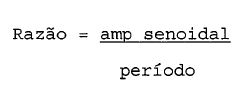
A finalidade de se determinar essa razao e tentar normalizar os gabaritos de onda senoidal entre si pelo ajuste da amplitude dos gabaritos de onda senoidal. Por exemplo, se a razao for muito elevada, indica que o gabarito de onda senoidal 384 e muito alto e fino, como mostrado, por exemplo , na Figura 16A. Se a razao e muito baixa, o gabarito de onda senoidal 3 86 e muito baixo e largo, como mostrado, por exemplo na Figura 16B. E preferivel nao comparar esses gabaritos altos e finos 384 ou gabaritos baixos e largos 386 com a forma de onda inspiratoria efetiva do paciente porque o ajuste entre esses dois padroes de onda nao e tipicamente muito bom e nao produz resultados significativos.The purpose of determining this ratio is to try to normalize the sine wave templates with each other by adjusting the amplitude of the sine wave templates. For example, if the ratio is very high, it indicates that the
Para responder por essas condigoes, a presente invengao ajusta a razao do gabarito de onda senoidal. A Figura 17 ilustra uma curva de normalizagao 390 que e utilizada para ajustar a razao dos gabaritos de onda senoidal. A curva de normalizagao 390 inclui uma regiao linear 392 onde nao e feito ajuste de razao. Acima da regiao linear 392, isto e, onde o gabarito de onda senoidal tern uma razao que e demasiadamente elevada, a curva de normalizagao 390 inclui uma primeira regiao 394 que ajusta para baixo a razao e uma regiao de grampeamento 396. Na modalidade exemplar ilustrada, a razao ajustada e grampeada em 36, nao importa quao elevada seja a razao efetiva. Abaixo da regiao linear 392, isto e, onde o gabarito de onda senoidal tern uma razao que e demasiadamente baixa, a curva de normalizagao 390 inclui uma segunda regiao 398 que ajusta para cima a razao e uma regiao de grampeamento 400. Na modalidade exemplar ilustrada, a razao ajustada e grampeada em 8 nao importa quao baixa seja a razao efetiva.To account for these conditions, the present invention adjusts the ratio of the sine wave template. Figure 17 illustrates a
A razao ajustada determinada a partir da relapao mostrada, por exemplo, na Figura 17, e utilizada para ajustar a amplitude do gabarito de onda senoidal, com o periodo sendo mantido constante. Por exemplo, a Figura 18A ilustra um gabarito de onda senoidal 4 02 onde a razao e demasiadamente baixa, significando que o gabarito de onda senoidal e demasiadamente achatado. Um gabarito de onda senoidal corrigido 404 tambem e mostrado indicando como o a juste da razao de forma eficaz aumenta a amplitude do gabarito de onda senoidal. A Figura 18B ilustra um gabarito de onda senoidal 406 onde a razao e demasiadamente elevada, significando que o gabarito de onda senoidal e demasiadamente alto. Um gabarito de onda senoidal corrigido 408 tambem e mostrado indicando como o ajuste da razao diminui efetivamente a amplitude do gabarito de onda senoidal.The adjusted ratio determined from the ratio shown, for example, in Figure 17, is used to adjust the amplitude of the sine wave template, with the period being kept constant. For example, Figure 18A illustrates a
Apos o gabarito de onda senoidal que corresponde ao fluxo inspiratorio do paciente ser determinado e corrigido, se necessario, o volume do gabarito de onda senoidal corrigido e calculado utilizando qualquer tecnica convencional. Em uma computaqao analogica, isto e realizado pela integraqao sobre o gabarito de onda senoidal corrigido a partir do ponto de partida ate o ponto final. Em um processo digital, isto e realizado somando os fluxos a partir do ponto de partida ate o ponto final e dividindo pelo numero de somas nesse processo.After the sine wave template that corresponds to the patient's inspiratory flow is determined and corrected, if necessary, the volume of the sine wave template is corrected and calculated using any conventional technique. In analog computing, this is accomplished by integrating over the corrected sine wave template from the starting point to the end point. In a digital process, this is done by adding the flows from the starting point to the end point and dividing by the number of sums in that process.
A Figura 19A ilustra uma forma de onda inspiratoria exemplar de paciente 410 e um gabarito de onda senoidal 412 determinada como discutido acima. Pode ser reconhecido a partir do exame dessa Figura que permanece um grau relativamente grande de desvio entre a forma de onda inspiratoria do paciente 410 e um gabarito de onda senoidal 412. A presente invenpao e responsavel por esse desvio deslocando efetivamente o gabarito de onda senoidal, como indicado pela seta 414, para cobrir a forma de onda inspiratoria do paciente.Figure 19A illustrates an exemplary patient
Em uma modalidade preferida da presente invenpao, o deslocamento do gabarito para cobrir a forma de onda inspiratoria do paciente e realizado determinando um centro C da forma de onda inspiratoria do paciente e utilizando esse centro como um novo centro para o gabarito de onda senoidal. O centro C da forma de onda inspiratoria do paciente 410 e determinada encontrando os pontos 416 e 418 na forma de onda inspiratoria que corresponde ao valor FFB. A descoberta dos pontos 416 e 418 na forma de onda inspiratoria que corresponde ao valor FFB e realizada buscando para cima ou para baixo a partir dos pontos de marco conhecidos 366 e 368, que correspondem ao valor de base senoidal (1/2 FFB). Essa busca e indicada pelas setas 420 e 422. Apos os pontos FFB serem localizados na forma de onda inspiratoria 410, o centro C da forma de onda inspiratoria e tornado como metade da distancia entre esses pontos FFB (416 e 418). Agora que o centro C da forma de onda inspiratoria e localizado, os pontosIn a preferred embodiment of the present invention, displacement of the template to cover the patient's inspiratory waveform is performed by determining a center C of the patient's inspiratory waveform and using that center as a new center for the sine wave template. The center C of the patient's
de localizapao definindo o gabarito de onda senoidal 412 podem ser recalculados em torno desse centre.of localization defining the
Com referenda agora a Figura 20, um nivel de achatamento e calculado determinando o volume da forma de onda inspiratoria 410 acima do nivel de linha de base plana de achatamento (FFB) entre o ponto de volume de 2 0% e o ponto de volume de 80%. De preferencia, uma constante de ponderapao e aplicada a esse resultado para torna-lo menos sensivel a alterapoes leves no formato da forma de onda inspiratoria.With reference now to Figure 20, a flattening level is calculated by determining the volume of the
Em um processador digital, o achatamento pode ser determinado como a seguir: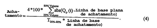
Nessa relapao, o valor constante 4 e a constante de ponderapao que torna essa determinapao menos sensivel a alterapoes no formato da forma de onda inspiratoria. O valor constante 100 e selecionado de modo que o valor de achatamento seja expresso como uma percentagem. De modo interessante, o valor de achatamento e grande quando a forma de onda inspiratoria e senoidal e poderia ser zero se a forma de onda inspiratoria fosse perfeitamente plana.In this relationship, the
Com referenda agora a Figura 21, o arredondamento e calculado como a diferenpa entre uma forma de onda inspiratoria de paciente 410 e o gabarito de onda senoidal 412 determinado como discutido acima entre o ponto de volume de 20% e o ponto de volume de 80%. Essa diferenpa e mostrada na Figura 21 como areas sombreadas 430. Uma constants de ponderaqao tambem e aplicada de preferencia a determinaqao de arredondamento para tornar a mesma menos sensivel a leves alteraqoes no formato da forma de onda inspiratoria.With reference now to Figure 21, rounding is calculated as the difference between a patient
Em um processador digital, pode-se determinar o arredondamento como a seguir:
De modo interessante, o valor de arredondamento e grande quando a forma de onda inspiratoria e plana e poderia ser zero se a forma de onda inspiratoria fosse uma senoide perfeita.Interestingly, the rounding value is large when the inspiratory waveform is flat and could be zero if the inspiratory waveform were a perfect sinusoid.
Com referenda agora a Figura 22, a assimetria e calculada primeiramente segmentando uma forma de onda inspiratoria 432 em regioes 434, 436 e 438. Cada regiao corresponde a 1/3 da duraqao da forma de onda inspiratoria. Uma quantidade predeterminada dos fluxos superiores em cada regiao e tirada em media. Por exemplo, em uma modalidade preferida da presente INVENÇÃO, os 5% superiores do fluxo em cada regiao sao tornados em media. Um numero de assimetria para a forma de onda inspiratoria e calculado como os 5% da regiao media 436 divididos pelos 5% da regiao esquerda. Dito de outra forma, o numero de assimetria e calculado como:
Pode ser reconhecido que o modo especlfico no qual a forma de onda inspiratoria e segmentada, e a percentagem de fluxo de cada que sao analisados para se determinar o valor de assimetria estao sujeitos a variapao.It can be recognized that the specific mode in which the inspiratory waveform is segmented, and the percentage of flow of each that are analyzed to determine the value of asymmetry are subject to variation.
O modulo de detecpao de CPAP automatico 350 desempenha dois tipos de analise de tendencia em cada um dos parametros de respirapao monitorados, isto e, dados de fluxo de pico ponderado, achatamento, arredondamento e assimetria coletados durante qualquer periodo de tempo, que e tipicamente 2,5 a 20 minutos. O primeiro e uma analise de tendencia a longo prazo e o segundo e mencionado como analise de tendencia a curto prazo. Contudo, cada tipo de analise de tendencia requer primeiro a coleta dos dados para a analise. Naturalmente, a medida que mais dados sao inseridos na analise de tendencia, maior a probabilidade de que a analise sera representative da resposta do paciente.The automatic
Como mostrado na Figura 23, os dados de parametro de respirapao para os ciclos de respirapao de um paciente 440 sao agrupados em conjuntos, com cada conjunto contendo os dados associados a multiples ciclos de respirapao. Em uma modalidade atualmente preferida, cada conjunto inclui dados de parametro respiratorios para quatro ciclos de respirapao .As shown in Figure 23, the breath parameter data for a 440 patient's breath cycles are grouped into sets, with each set containing the data associated with multiple breath cycles. In a currently preferred embodiment, each set includes respiratory parameter data for four breathing cycles.
Os parametros de respirapao ou respiratorios, isto e, fluxo de pico ponderado QWpeak, arredondamento, achatamento e assimetria, para cada respirapao sao calculados como discutido acima. Os dados de fluxo de pico ponderado para quaW.j&tro respirapoes, por exemplo, sao tornados em media e utilizados para determinar um unico valor de ponto para uso na analise de tendencia. Esse mesmo processo e conduzido para os outros parametros respiratorios de arredondamento, achatamento e assimetria. 0 resultado e um acumulo de dados, como indicado pelo grafico 442, que e utilizado para fins de analise de tendencia.Breathing or breathing parameters, i.e., weighted peak flow QWpeak, roundness, flattening and asymmetry, for each breath are calculated as discussed above. Peak flow data weighted for four breaths, for example, are averaged and used to determine a single point value for use in trend analysis. This same process is conducted for the other rounding, flattening and asymmetry respiratory parameters. The result is an accumulation of data, as indicated by
A Figura 24 ilustra um grafico de analise de tendencia exemplar, onde cada ponto representa os dados de parametro respiratorio tirados em media durante quatro ciclos de respirapao. A analise de tendencia desses dados envolve determinar uma linha de ajuste de mfnimos quadrados, tambem mencionada como uma linha de melhor ajuste 444, para os pontos de dados. Pode ser reconhecido que a inclinapao da linha de melhor ajuste 444 e indicativa do grau com o qual a tendencia dos dados esta mudando. A seguir, um desvio padrao 446 dos pontos de dados em torno dessa linha de melhor ajuste e determinado sobre o intervalo de tempo de interesse.Figure 24 illustrates an exemplary trend analysis graph, where each point represents the respiratory parameter data averaged over four breath cycles. Trend analysis of these data involves determining a least square fit line, also referred to as a best fit line 444, for the data points. It can be recognized that the slope of the best-fit line 444 is indicative of the degree to which the data trend is changing. Next, a
Uma variedade de tipos diferentes de analise pode ser feita com base nesses dados. Por exemplo, a presente invenpao considera a determinapao de uma alterapao em percentagem e um valor de diferenpa dos dados de tendencia. A percentagem de alterapao e calculada como: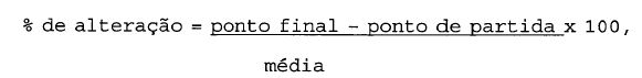
444 proximo ao inicio dos dados coletados, como ponto 450, e a media e o valor medio dos pontos de dados entre os pontos de partida e final. Um calculo equivalente para a percentagem de alterapao pode ser expresso como:
% de alterapao = inclinapao x comprimento de tendencia x 100, media (7b)onde inclinapao e a inclinapao da linha de melhor ajuste 444 e o comprimento de tendencia e o comprimento da tendencia, indicado como o tempo entre o ponto de partida e o ponto final.% change = inclination x trend length x 100, mean (7b) where inclination is the inclination of the best fit line 444 and the trend length and trend length, indicated as the time between the starting point and the point Final.
O valor de diferenpa e calculado como a diferenpa entre o valor do ponto final e do ponto de partida expresso como:valor de diferenpa = ponto final ponto de partida (7c)The difference value is calculated as the difference between the end point value and the starting point expressed as: difference value = end point starting point (7c)
A representaqao equivalente dessa equapao pode ser expressa como:valor de diferenpa = inclinapao x comprimento de tendencia (7d)The equivalent representation of this equation can be expressed as: difference value = slope x trend length (7d)
De acordo com uma modalidade preferida da presente invenpao, ao analisar os dados de fluxo de pico ponderados, apenas a percentagem de alterapao e utilizada. Ao analisar os dados de arredondamento, achatamento e assimetria, apenas o valor de diferenpa dos dados de tendencia e utilizado porque, em uma modalidade preferida da presente invenpao, essas medidas novas ja sao representadas como percentagens. Uma janela de erro, definida por uma percentagem de alterapao ou diferenpa como descrito acima, e comparada com limites predeterminados para determinar se a alteraqao nos dados, isto e, a tendencia, excedeu niveis aceitaveis. Deve ser observed© que o tipo de analise (alteraqao ou diferenqa de percentage™) depende do tipo de dados novos utilizados na analise de tendencia.According to a preferred embodiment of the present invention, when analyzing the weighted peak flow data, only the percentage of change is used. When analyzing the rounding, flattening and asymmetry data, only the difference value of the trend data is used because, in a preferred embodiment of the present invention, these new measures are already represented as percentages. An error window, defined by a percentage of change or difference as described above, is compared to predetermined limits to determine whether the change in the data, i.e., the trend, has exceeded acceptable levels. It should be noted that the type of analysis (change or difference in percentage ™) depends on the type of new data used in the trend analysis.
Como observado acima, o modulo de detecqao de CPAP automatico 350 olha uma tendencia a curto prazo e uma tendencia a longo prazo dos pontos de dados acumulados note que cada ponto de dados contem uma media dos dados de parametros para quatro ciclos de respiraqao. Ao desempenhar a analise de tendencia a longo prazo, a percentagem de alteraqao ou o valor de diferenqa (dependendo do parametro de interesse) e avaliado com o passar do tempo para determinar se esses criterios de analise de tendencia estao compreendidos fora de limites predeterminados. Ao realizar a tendencia a curto prazo, cada ponto de dados recentemente coletado e comparado com os pontos de dados ja coletados em um esforqo para localizar anomalias nos parametros monitorados em relaqao aos dados inclinados.As noted above, the automatic
Para desempenhar a analise de tendencia a longo prazo, a linha de melhor ajuste para os dados inclinados, que tern um desvio padrao associado para os pontos de dados em torno daquela linha, e utilizada para determinar uma janela de erro de tendencia. A janela de erro de tendencia representa uma gama de erros para os dados de tendencia. A janela de erro de tendencia e uma funqao do desvio padrao para a linha de melhor ajuste, o numero de pontos de dados utilizados no calculo de tendencia, e o nivel de confianpa desejado, e e determinado utilizando qualquer tecnica convencional, como utilizando uma tabela de consulta, apos estabelecer os criterios de entrada (desvio padrao, no. de amostras (pontos de dados) e nivel de confianpa).To perform long-term trend analysis, the best fit line for the slanted data, which has an associated standard deviation for the data points around that line, is used to determine a trend error window. The trend error window represents a range of errors for the trend data. The trend error window is a function of the standard deviation for the best fit line, the number of data points used in the trend calculation, and the desired confidence level, and is determined using any conventional technique, as using a consultation, after establishing the entry criteria (standard deviation, number of samples (data points) and level of confidence).
Na presente invenpao, o nivel de confianpa utilizado na selepao da janela de erro de tendencia e determinado com base em uma avaliapao empirica dos dados. Foi determinado a partir dessa analise empirica que, para fins da presente invenpao, um nivel de confianpa de 80% e apropriado para a janela de erro de tendencia. Contudo, aqueles versados no estado da tecnica podem apreciar que esse nivel pode variar e ainda fornecer resultados significativos. Em essencia, na selepao de um nivel de confianpa de 80%, a presente invenpao busca dizer, com um nivel de confianpa de 80%, que a linha de melhor ajuste, com sua dispersao de dados associada, representa a verdadeira tendencia dos dados sendo analisados.In the present invention, the level of confidence used in selecting the trend error window is determined based on an empirical assessment of the data. It was determined from this empirical analysis that, for the purposes of the present invention, an 80% confidence level is appropriate for the trend error window. However, those skilled in the art can appreciate that this level may vary and still provide significant results. In essence, in selecting an 80% confidence level, the present invention seeks to say, with an 80% confidence level, that the best fit line, with its associated data dispersion, represents the true trend of the data being analyzed.
Quando uma janela de erro de tendencia e determinada, essa faixa de erros e convertida em uma janela de erros com base no valor de diferenpa ou a percentagem de alterapao discutida acima. Isto pode ser realizado aplicando-se os calculos discutidos nas equapoes (7b) e (7d) da janela de erro de tendencia. Nesse caso, a inclinapao da linha de melhor ajuste seria representada por uma faixa de inclinapoes que levam em considerapao a linha de melhor ajuste 444 e seu erro de tendencia associado. Apos a janela de erro ser convertida em uma diferenpa ou percentagem de alterapao, e fornecida do detector de CPAP automatico 350 para o monitor de CPAP automatico 352, que utiliza essas informagoes baseadas em tendencia, como discutido abaixo, para julgar as alteragoes de resposta do paciente a pressao fomecida.When a trend error window is determined, that range of errors is converted into an error window based on the difference value or percentage of change discussed above. This can be accomplished by applying the calculations discussed in equations (7b) and (7d) of the trend error window. In this case, the slope of the best fit line would be represented by a range of slopes that take into account the best fit line 444 and its associated trend error. After the error window is converted into a difference or percentage of change, it is provided from the
A analise de tendencia a curto prazo tenta distinguir resposta de paciente relativamente rapida a pressao fomecida. Portanto, em vez de olhar as alterapoes nos dados de tendencia com o passar do tempo, a fungao de analise de tendencia a curto prazo do modulo de detecgao de CPAP automatico 350 em combinagao com o modulo de monitoragao de CPAP automatico 352, analisa cada ponto de dado a medida que o mesmo e gerado contra dois criterios de detecgao. O modulo de detecgao de CPAP automatico estabelece os criterios de tendencia a curto prazo, e o modulo de monitoragao de autoCPAP 350 analisa o ponto de dados recentemente gerado contra esses criterios.Short-term trend analysis attempts to distinguish patient response relatively quickly from the pressure provided. So instead of looking at changes in trend data over time, the short-term trend analysis function of the automatic
O primeiro criterio de tendencia a curto prazo determinado pelo modulo de detecgao de CPAP automatico e um intervalo de previsao. O objetivo do intervalo de previsao e fornecer uma faixa de valores contra os quais o ponto de dados recentemente gerado e comparado. O intervalo de previsao e determinado utilizando tecnicas de analise estatistica padrao, com base no desvio padrao dos pontos de dados sobre a linha de melhor ajuste, o numero de amostras ou pontos de dados no calculo de analise de tendencia e o nivel de confianga desejado. Na presente invengao, o nivel de confianga utilizado para selecionar o intervalo de previsao e determinado com base em uma avaliapao empirica dos dados. Foi determinado dessa analise empirica que, para fins da analise de tendencia a curto prazo, um nivel de confianpa de 95% e apropriado. Contudo, aqueles versados no estado da tecnica podem reconhecer que esse nivel pode variar e ainda fornecer resultado significativos. Com base nesses criterios, o intervalo de previsao representa uma faixa de valores nos quais temos 95% de confianpa de que o proximo ponto de dados gerado estara compreendido nessa faixa de valores.The first short-term trend criterion is determined by the automatic CPAP detection module and a forecast range. The purpose of the forecast range is to provide a range of values against which the newly generated data point is compared. The forecast interval is determined using standard statistical analysis techniques, based on the standard deviation of the data points on the best fit line, the number of samples or data points in the trend analysis calculation and the desired confidence level. In the present invention, the confidence level used to select the forecast range is determined based on an empirical assessment of the data. From this empirical analysis it was determined that, for the purposes of short-term trend analysis, a 95% confidence level is appropriate. However, those skilled in the art can recognize that this level can vary and still provide significant results. Based on these criteria, the forecast range represents a range of values in which we are 95% confident that the next data point generated will be included in that range of values.
O segundo criterio de tendencia a curto prazo determinado pelo modulo de detecpao de CPAP automatico e simplesmente um "inicio de ponto de dado de tendencia", que e um ponto de dado na linha de melhor ajuste no inicio da coleta de dados. 0 inicio de ponto de dados de tendencia e similar ao ponto de dados 450 na Figura 24. Como anteriormente descrito para a tendencia a longo prazo, uma percentagem de alterapao e diferenpa sao calculados para o curto prazo. Isto e realizado pelo uso das equapoes (7a) e (7c) descritas acima. Para o calculo de curto prazo, o ponto final e definido como valor do ponto de dados atual, e o ponto de partida e definido como o inicio do ponto de tendencia, similar ao ponto de dados 450 na Figura 24. Como discutido abaixo, o intervalo de previsao e a percentagem de alterapao a curto prazo (ou diferenpa, isto e, dependendo da medipao de respirapao individual, compativel com aquela descrita para a tendencia a longo prazo) sao fornecidos a partir do modulo de detecpao de CPAP automatico para o modulo de monitorapao de CPAP automatico 352.The second short-term trend criterion determined by the automatic CPAP detection module is simply a "start of trend data point", which is a data point on the best fit line at the beginning of data collection. The start of the trend data point is similar to the
O modulo de monitorapao de CPAP automatico 352 utiliza a informapao de tendencia fornecida pelo modulo de detecpao de CPAP automatico 350 em um processo de votapao para determinar a resposta do paciente a uma pressao sendo fornecida a via aerea. Por exemplo, o monitor de CPAP auto-matico determina se o perfil da forma de onda de fluxo de paciente esta ou nao aperfeipoando ou degradando, desse modo indicando se a restripao de fluxo de via aerea pode estar melhorando ou degradando.The automatic
A Figura 25 e um grafico 459 explicando por ilustrapao, a votapao realizada sobre as informapoes fornecidas pela analise de tendencia a longo prazo. No centro do grafico 459 encontra-se uma janela de votapao 461 que e limitada por um limite superior 462 e um limite inferior 464. Ha tres niveis de votapao nesse grafico: 1 = melhorando, 0 = sem alterapao, -1 = piorando.Figure 25 is a
Os dados de tendencia, juntamente com seu erro estatistico associado, que corresponde a uma janela de erro 464 calculada durante a analise de tendencia a longo prazo realizada pelo detector de CPAP automatico, sao comparados com limites 460 e 462. A firn de produzir um voto de 1, a janela de erro inteira deve exceder um nivel limite atribuido. Esse nivel de limite varia de medipao para medipao, porem tipicamente varia de 7% a 8%. Na Figura 25, o valor de 8% e selecionado. Se a faixa de erro inteira 4 64 estiver acima do nivel de limite 460, um voto de 1 e gerado, como indicado pela regiao 466. Similarmente, se a faixa de erro inteira 464 estiver abaixo do nivel de limite 462, como indicado pela regiao 468, um voto de -1 e gerado. De outro modo, um voto de zero (0) e gerado, regiao 470.The trend data, together with its associated statistical error, which corresponds to a 464 error window calculated during the long-term trend analysis performed by the automatic CPAP detector, are compared with
A analise de tendencia a curto prazo descrita acima e o esquema de votapao a curto prazo descrito abaixo sao elaborados para detectar alterapoes a curto prazo ou relativamente subitas no perfil de fluxo do paciente. Isto e realizado comparando um unico agrupamento de respirapoes (isto e, um ponto de dado, que contem 4 respirapoes) com o primeiro e segundo criterios de tendencia a curto prazo discutidos acima, e determinar se aquele grupo mostrou uma alterapao estatisticamente significativa com relapao aos dados inclinados a longo prazo.The short-term trend analysis described above and the short-term voting scheme described below are designed to detect short-term or relatively sudden changes in the patient's flow profile. This is done by comparing a single grouping of breaths (ie, a data point, which contains 4 breaths) with the first and second short-term trend criteria discussed above, and determining whether that group showed a statistically significant change with respect to the long-term skewed data.
Se (1) o ponto de dado recentemente gerado for igual a ou fora do intervalo de previsao e (2) o ponto de dado diferir do inicio de ponto de dado de tendencia em um valor limite predeterminado, o ponto de dado (isto e, grupo de respirapao) e considerado como representando uma alterapao significativa em relapao ao inicio da tendencia a longo prazo. Portanto, se essas duas condipoes forem atendidas, a tendencia a curto prazo gera um voto de 1 ou -1, dependendo de se o ponto de dados esta acima ou abaixo do inicio do ponto de dado de tendencia. De outro modo, um voto de zero (0) e gerado. 0 limite para a percentagem de alterapao ou diferenpa entre o ponto de dado e o inicio do ponto de dadode tendencia utilizado para inclinapao a curto prazo varia de medipao para medipao, porem tipicamente varia de 9% a14%.If (1) the newly generated data point is equal to or outside the forecast range and (2) the data point differs from the start of the trend data point by a predetermined threshold value, the data point (i.e., breathing group) is considered to represent a significant change from the beginning of the long-term trend. Therefore, if these two conditions are met, the short-term trend generates a vote of 1 or -1, depending on whether the data point is above or below the start of the trend data point. Otherwise, a vote of zero (0) is generated. The limit for the percentage of change or difference between the data point and the start of the trend point used for short-term inclination varies from measurement to measurement, but typically ranges from 9% to 14%.
Apos um voto a longo prazo e um voto a curto prazo ter sido emitido para cada medipao de respirapao individual, os votos de todas as medipoes sao entao acumulados em um voto unico e final. A seguinte tabela resume o processo de votapao final: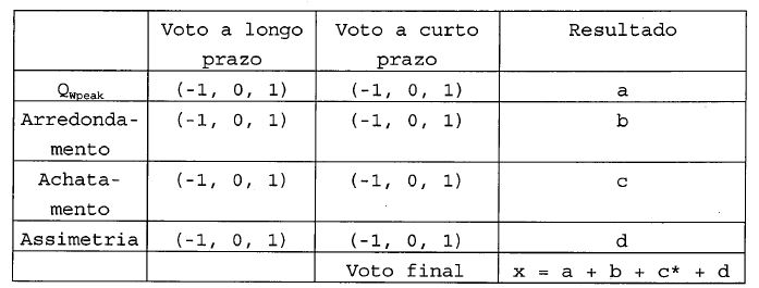
O valor colocado na coluna "Resultado" para cadaparametro de respirapao e o valor do voto a longo prazo, a menos que o voto a longo prazo seja zero. Se o voto a longo prazo for zero, o valor do voto a curto prazo e colocado na coluna resultados para aquele parametro de respirapao. Os resultados sao somados para gerar o voto final.The value placed in the "Result" column for each breath meter is the value of the long-term vote, unless the long-term vote is zero. If the long-term vote is zero, the short-term vote is placed in the results column for that breathing parameter. The results are added together to generate the final vote.
A unica outra exigencia implementada pela presente invenpao e que o parametro de respirapao de achatamento e ignorado ao somar para o voto final se o resultado de achatamento for diferente de zero e se for incompativel com os outros parametros de respirapao de votapao diferentes de zero associados ao formato da forma de onda inspiratoria, isto e, arredondamento e assimetria. E por esse motive que um asterisco e colocado ao lado de "c" na tabela acima, significando que em certas situapoes o valor de achatamento "c" e ignorado. Por exemplo, o resultado para achatamento el, e 5 o parametro de arredondamento ou o parametro de assimetria e -1, o resultado de achatamento e ignorado na soma para o vo-to final. Similarmente, se o resultado para achatamento for -1, e o parametro de arredondamento ou de assimetria for 1, o resultado de achatamento e ignorado na soma para o voto 10 final.The only other requirement implemented by the present invention is that the flattening breathing parameter is ignored when adding to the final vote if the flattening result is different from zero and if it is incompatible with the other nonzero breathing breathing parameters associated with the shape of the inspiratory waveform, that is, roundness and asymmetry. It is for this reason that an asterisk is placed next to "c" in the table above, meaning that in certain situations the flatness value "c" is ignored. For example, the result for flattening el,
O voto final "x" da tabela acima pode ter uma faixa de -4 a 4 e e utilizado para determinar as tres principals condipoes sobre o perfil da forma de onda de fluxo do paciente. A condipao do fluxo inspiratorio do paciente tam15 bem e indicativa da resposta do paciente a pressao sendo fornecida para a via aerea. As tres principals condipoes que resumem a resposta de um paciente a pressao, e o valor de voto final associado a cada condipao, sao fornecidas abaixo:1) degradapao estatisticamente significativa, x < -22) estatisticamente sem alterapao, -2 < x < 23) aperfeipoamento estatisticamente significativo x > 2Todos essas tres condipoes podem ser determinadas 25 independentes de se o controlador de CPAP automatico esta aumentando, diminuindo ou mantendo a pressao constante. A tabela que se segue resume onde cada condipao (1) , (2) ou(3) esta compreendida para cada valor de x:
A seguinte tabela resume onde cada condipao (1) , (2), (2,5) ou (3) esta compreendida para cada valor de xnessa situapao: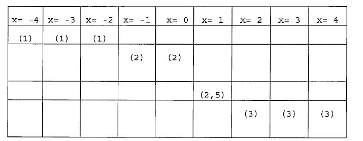
Deve ser entendido que um numero maior ou menor decondipoes pode ser fornecido dependendo de quao sintonizada a camada de controle de CPAP automatico deve estar com alterapoes na condipao do paciente.It should be understood that a greater or lesser number of deconditions can be provided depending on how tuned the automatic CPAP control layer must be with changes in the patient's condition.
O controlador de CPAP automatico utiliza o nivel de votapao final descrito acima, que e uma indicapao da resposta do paciente a pressao sendo fornecida a sua via aerea pelo sistema de suporte de pressao, juntamente com seu modo de operapao atual, para determinar quais medidas tomar. Tres casos gerais sao apresentados abaixo para descrever o comportamento do controlador de CPAP automdtico.The automatic CPAP controller uses the final voting level described above, which is an indication of the patient's response to the pressure being delivered to your airway by the pressure support system, along with your current mode of operation, to determine what steps to take . Three general cases are presented below to describe the behavior of the automatic CPAP controller.
A Figura 26 ilustra uma curva de pressao 500 transmitida pelo sistema de suporte de pressao durante o Caso 1. Quando o sistema de suporte de pressao e ligado, eleentrara em um periodo de manutenpao 502 e coletara dados.Figure 26 illustrates a
Em uma modalidade preferida, esse periodo de manutenpao dura 5 minutos. Contudo, a durapao do periodo de manutenpao pode ser um valor diferente de 5 minutos, desde que tempo suficiente decorra para coletar uma quantidade significativa de dados. Ao termino desse periodo, o controlador de CPAP automatico 354 inicia um estado de recuperapao no qual a pressao de paciente e deslocada para cima lentamente, com um aumento alvo de 1,5 cmH2O, e em uma taxa de aumento de aproximadamente 0,5 cmH20/min.In a preferred embodiment, this maintenance period lasts for 5 minutes. However, the duration of the maintenance period can be a different value than 5 minutes, as long as enough time elapses to collect a significant amount of data. At the end of this period, the
Durante esse deslocamento, os dados de tendencia sao continuamente examinados pelo monitor de CPAP automatico 352 utilizando as quatro condipoes (1), (2), (2,5) e (3) para determinar se o perfil de fluxo de paciente experimentou degradapao estatisticamente significativa condipao (1) , estatistica sem alterapao condipao (2), aperfeipoamento estatisticamente marginal condipao (2,5), ou aperfeipoamento estatisticamente significativo condipao (3) durante o periodo de deslocamento. Contudo, nenhuma medida e tomada sobre essa determinapao ate ~2,5 minutos terem decorrido desde o inicio do aumento de pressao. Essa janela de bloqueio de 2,5 minutos 504 e fornecida para permitir que o sistema colete dados suficientes para fins de tendencia. Pode ser reconhecido que a durapao do intervalo de bloqueio pode variar, por exemplo, entre 2-4 minutos. Contudo, quanto mais longa essa janela de bloqueio, menos responsive sera o sistema para tratar quaisquer disturbios de respirapao em potencial.During this shift, trend data is continuously examined by the automatic CPAP monitor 352 using the four conditions (1), (2), (2.5) and (3) to determine whether the patient flow profile has experienced statistically degradation significant condition (1), statistically unchanged condition (2), statistically significant improvement (2.5), or statistically significant improvement (3) during the period of displacement. However, no action is taken on this determination until ~ 2.5 minutes have elapsed since the start of the pressure increase. This 2.5
Se a forma de onda de fluxo inspiratorio do paciente tiver aperfeipoado ou degradado durante deslocamento 506, o deslocamento e a inclinapao continuam ate que o aperfeipoamento ou degradapao cesse, por exemplo, a condipao do paciente mude de (3) para (2,5) ou a condipao do paciente mude de (1) para (2). Entao, um periodo de manutenpao de 5 minutos sera iniciado, como indicado pela curva de pressao 508. Se nao houve aperfeipoamento durante o deslocamento, isto e, o perfil de fluxo inspiratorio do paciente permanecer igual condipao (2) ou condipao (2,5), o controlador de CPAP automatico 354 diminui a pressao 1,5 cmH20, como indicado pela curva de pressao 510, e um periodo de manutenpao de 5 minutos 512 e entao iniciado. Essa sequencia de controle de pressao se destina a determinar se existe limitapao de fluxo nas formas de onda, e para localizar uma pressao ideal na qual a limitapao de fluxo nao mais exista. Se a limitapao de fluxo for detectada durante qualquer periodo de manutenpao (indicando que o paciente pode ter alterado a posipao ou estagio de sono) , o deslocamento para cima lento sera novamente iniciado.If the patient's inspiratory flow waveform has perfected or degraded during
Durante o curso da terapia de suporte de pressao, que tipicamente se repete durante toda a noite, controladores de nivel mais elevado, como controlador de ronco 144 ou controlador de apneia/hipopneia 168, podem temporariamente assumir o controle e executar alterapoes de pressao como discutido acima. Apos terminarem todos os controladores de prioridade elevada ativos, o controle e retornado ao controlador de CPAP automatico 354. Apos receber controle de um controlador de prioridade mais elevada, o controlador de CPAP automatico desempenha as mesmas apoes como descrito no Caso 1 acima, com a excepao de que o periodo de manutenpao inicial de 5 minutos e substituido por um periodo de ~3 a 3,5 minutos.During the course of pressure support therapy, which typically recurs throughout the night, higher level controllers, such as
Quando o ultimo periodo de manutenpao de 5 minutos do Caso 1 ou Caso 2 for concluido, como indicado pela curva de pressao 520 nas Figuras 27A e 27B, a proxima sequencia de busca e iniciada. Nessa sequencia de busca, a pressao fornecida pelo sistema e lentamente reduzida em uma taxa de 0,5 cmH20/minuto, como indicado pela curva 522. Antes de iniciar a diminuipao em pressao, as tendencies de medipao de respirapao sao inicializadas com ate os tres ultimos minutos de dados disponiveis.When the last 5-minute maintenance period for
Apos deslocamento para baixo de 0,5 cmH20, os dados de tendencia sao entao continuamente examinados para determinar se o perfil de fluxo inspiratorio do paciente degradou ou nao durante o periodo de deslocamento. Nessa analise de tendencia, apenas as tres condipoes de paciente (1), (2) e (3) sao levadas em considerapao. Se nao for detectada degradapao de perfil de fluxo de paciente (condipao (2)), o deslocamento e inclinapao continuarao ate que a pressao minima do sistema Pmin seja atingida, como mostrado na Figura 27A. Posteriormente, o controlador de CPAP automatico 354 inicia o controle de pressao do Caso 1 discutido acima e inicia um periodo de manutenpao de 5 minutos 502.After displacement down to 0.5 cmH20, trend data is then continuously examined to determine whether the patient's inspiratory flow profile has degraded or not during the displacement period. In this trend analysis, only the three patient conditions (1), (2) and (3) are taken into account. If no degradation of the patient flow profile (condition (2)) is detected, the displacement and inclination will continue until the minimum pressure of the Pmin system is reached, as shown in Figure 27A. Thereafter, the
Se durante a diminuipao de pressao o perfil de fluxo inspiratorio de paciente degradar, por exemplo, se mover da condipao (2) para a condipao (1) , a pressao do paciente sera rapidamente aumentada 1,5 cmH20, curva 526, e entao mantida constante por ate 10 minutos, curva 528. Vide a Figura 27B. Apos terminar o periodo de manutenpao de 10 minutos, o controlador de CPAP automatico 354 entra diretamente no estado de recuperapao discutido acima com relapao ao Caso 1, e inicia o aumento de pressao 506.If during the pressure decrease the patient's inspiratory flow profile degrades, for example, moving from condition (2) to condition (1), the patient's pressure will be rapidly increased by 1.5 cmH20,
Essa sequencia inteira se destina a determinar a pressao na qual limitapao de fluxo ocorre e entao elevar a pressao ate um ajuste ideal. Essa sequencia e repetida durante toda a noite para localizar a pressao otima a medida que as condipoes do paciente mudam e melhorar o conforto mantendo a pressao tao baixa quanto pratico. Se a limitapao de fluxo for detectada durante qualquer periodo de manutenpao (indicando que o paciente pode ter mudado a posipao ou estagio de sono), o deslocamento para cima lento (estado de recuperapao) sera novamente iniciado.This entire sequence is intended to determine the pressure at which flow limitation occurs and then raise the pressure to an ideal setting. This sequence is repeated throughout the night to find the optimal pressure as the patient's condition changes and improve comfort by keeping the pressure as low as practical. If flow limitation is detected during any maintenance period (indicating that the patient may have changed the position or sleep stage), the upward slow movement (recovery state) will begin again.
Durante essa diminuipao de pressao, onde o controlador de CPAP automatico esta procurando um ponto de limitapao de fluxo potencial, a chance de ocorrer ronco e aumentada. Por esse motive, a presente invenpao considera a redupao do numero exigido de eventos de ronco de tres para dois, o que fara com que o modulo de monitorapao de ronco 142 solicite que o controlador de ronco assuma o controle. Isto aumenta efetivamente a sensibilidade do sistema ao ronco durante o intervalo de diminuipao de pressao.During this pressure decrease, where the automatic CPAP controller is looking for a potential flow limiting point, the chance of snoring is increased. For this reason, the present invention considers reducing the required number of snoring events from three to two, which will cause the
Durante qualquer periodo de manutenpao, como o periodo de manutenpao 502, 508, 512, 520 ou 528, o controlador de CPAP automatico 354 pode entrar no estado de recuperapao discutido acima no Caso 1 para tentar fornecer a pressao 6tima para o paciente. Isto pode ocorrer, por exemplo, se os dados de tendencies analisados durante a retenpao indicarem que o perfil de forma de onda inspiratoria do paciente esta experimentando uma degradapao estatisticamente significative (condipao (1)).During any maintenance period, such as the
Na sepao G acima, na qual a operapao da camada de controle de apneia/hipopneia e discutida, foi observado que o modulo de detecpao de A/H 164 nao pode detectar a diferenpa entre eventos de apneia/hipopneia obstrutivos e eventos de apneia/hipopneia centrais, porem compensa esse empecilho pelo modo no qual a pressao e fomecida ao paciente. Contudo, uma modalidade adicional da presente invenpao considera a detecpao da diferenpa entre eventos de apneia/hipopneia obstrutivos e eventos de apneia/hipopneia centrais A/H atraves do modulo de detecpao 164. Isto e realizado, por exem-plo, pela monitorapao da forma de onda inspiratoria do paciente durante o periodo de apneia/hipopneia, imediatamente apos o termino do periodo de apneia/hipopneia, ou durante esses dois periodos como discutido abaixo.In section G above, in which the operation of the apnea / hypopnea control layer is discussed, it was observed that the A /
Se for determinado que o paciente esta experimentando um evento de apneia/hipopneia obstrutivo, a pressao e fornecida ao paciente como discutido acima na Sepao G. Se, contudo, o paciente esta experimentando um evento de apneia/hipopneia central, e preferivel nao aumentar a pressao. E genericamente reconhecido que o aumento da pressao fornecida ao paciente nao trata um episodic de apneia/hipopneia central. Portanto, a presente invenpao considera manter a pressao fornecida ao paciente no nivel atual ou mesmo diminuir a pressao se o paciente for considerado como estando experimentando uma apneia/hipopneia central.If it is determined that the patient is experiencing an obstructive apnea / hypopnea event, pressure is provided to the patient as discussed above in Section G. If, however, the patient is experiencing a central apnea / hypopnea event, it is preferable not to increase the pressure. It is generally recognized that the increased pressure provided to the patient does not treat an episode of central apnea / hypopnea. Therefore, the present invention considers maintaining the pressure supplied to the patient at the current level or even decreasing the pressure if the patient is considered to be experiencing central apnea / hypopnea.
A manutenpao da pressao em seu nivel atual e realizada, de acordo com uma modalidade da presente invenpao, fazendo com que o modulo de detecpao de A/H rejeite o evento de apneia/hipopneia como um evento de apneia/hipopneia se for determinado como sendo um evento de apneia/hipopneia central. Em cujo caso, o sistema atua como se nenhum evento de apneia/hipopneia fosse detectado e nao solicita que o controlador de A/H 168 assuma controle do sistema. A presente invenpao tambem considera reduzir a pressao fornecida ao paciente se for determinado que o paciente esta experimentando uma apneia central.The maintenance of the pressure at its current level is performed, according to a modality of the present invention, causing the A / H detection module to reject the apnea / hypopnea event as an apnea / hypopnea event if it is determined to be a central apnea / hypopnea event. In which case, the system acts as if no apnea / hypopnea event was detected and does not request the A /
O modo no qual a presente invenpao discrimina entre eventos de apneia/hipopneia obstrutivo/restritivo e eventos de apneia/hipopneia central e discutido abaixo com referenda as Figuras 28-30, que ilustram formas de onda de fluxo de paciente exemplares durante eventos de apneia/hipopneia obstrutivo/restritivo (Figuras 28 e 30) e duran te um evento de apneia/hipopneia central (Figura 29). A determinapao do fato se o paciente esta experimentando um evento de apneia/hipopneia obstrutiva/restritiva ou um evento de apneia/hipopneia central e feita de preferencia pelo modulo de detecpao A/H 164, que fornece sua determinapao para o modulo de monitorapao de A/H 166 para acionar o controlador de A/H 168 de modo que o controle de pressao apropriado possa ser feito como discutido acima.The way in which the present invention discriminates between obstructive / restrictive apnea / hypopnea events and central apnea / hypopnea events is discussed below with reference to Figures 28-30, which illustrate exemplary patient flow waveforms during apnea / events obstructive / restrictive hypopnea (Figures 28 and 30) and during a central apnea / hypopnea event (Figure 29). The determination of whether the patient is experiencing an obstructive / restrictive apnea / hypopnea event or a central apnea / hypopnea event is preferably done by the A /
Em uma modalidade exemplar atualmente preferida, a forma de onda inspiratoria do paciente durante o periodo de apneia/hipopneia e monitorada para determinar se ele ou ela esta experimentando um evento de apneia/hipopneia obstrutiva/restritiva ou um evento de apneia/hipopneia central. Nas formas de onda de fluxo de paciente hipoteticas 600 e 602 nas Figuras 28 e 29, respectivamente, o evento de apneia/hipopneia comepa no ponto 604 e termina no ponto 606, que e determinado como discutido acima nas Sepoes G(3) e G(4) . Deve ser observado que as formas de onda 600 e 602 sao fornecidas para ilustrar uma tecnica utilizada por uma modalidade exemplar da presente invenpao, a firn de determinar se o paciente esta experimentando um evento de apneia/hipopneia obstrutiva/restritiva ou um evento de apneia/hipopneia central. Essas formas de onda podem nao estar em escala e podem nao representar de forma precisa um fluxo efetivo de paciente. As linhas tracejadas nas Figuras 28 e 29 ilustram o vale do fluxo do paciente que ocorre durante um evento de apneia/hipopneia. E nesse vale ou periodo de apneia/hipopneia que a presente invenpao examina o formato do fluxo do paciente, para determinar se ele ou ela esta experimentando um evento de apneia/hipopneia obstrutiva/restritiva ou um evento de apneia/hipopneia central.In a currently preferred exemplary modality, the patient's inspiratory waveform during the apnea / hypopnea period is monitored to determine whether he or she is experiencing an obstructive / restrictive apnea / hypopnea event or a central apnea / hypopnea event. In the hypothetical
Mais especificamente, os presentes inventores compreendem que durante um evento de apneia/hipopneia obstrutiva/restritiva, as caracterfsticas de formato da forma de onda inspiratoria do paciente tendem a apresentar as mesmas caracteristicas de formato associadas a um fluxo de ar restrito. A saber, durante um evento de apneia/hipopneia obstrutiva/restritiva, a forma de onda apresenta aumento em achatamento (se torna mais plana), uma diminuiqao em arredondamento (se torna menos redonda), um aumento em assimetria (se torna mais inclinado) (como mostrado na Figura 22) ou qualquer combinagao dessas caracteristicas.More specifically, the present inventors understand that during an obstructive / restrictive apnea / hypopnea event, the shape characteristics of the patient's inspiratory waveform tend to have the same shape characteristics associated with a restricted air flow. Namely, during an obstructive / restrictive apnea / hypopnea event, the waveform shows an increase in flatness (becomes flatter), a decrease in roundness (becomes less round), an increase in asymmetry (becomes more inclined) (as shown in Figure 22) or any combination of these features.
Por exemplo, na Figura 28, as formas de onda inspiratorias 610 que ocorrem durante o periodo de apneia/hipopneia entre os pontos 604 e 606 tendem a ter um grau aumentado de achatamento, uma ausencia de arredondamento, um aumento de assimetria ou qualquer combinagao dessas caracteristicas, indicando que a forma de onda 600 representa uma apneia/hipopneia obstrutiva/restritiva em vez de uma apneia/hipopneia central. Na Figura 29, por outro lado, as formas de onda inspiratorias 612 ocorrendo durante o periodo de apneia/hipopneia entre os pontos 604 e 606 tendem a nao ter um grau aumentado de achatamento, arredondamento relativamente normal e sem aumento em assimetria, indicando que a forma de onda 602 representa uma apneia/hipopneia central em vez de uma apneia/hipopneia central. Desse modo, a presente invenpao considera monitoragao de achatamento, arredondamento e assimetria das formas de onda que ocorrem durante o periodo de apneia/hipopneia atraves do modulo de detecpao de A/H 164, para determinar se o paciente esta experimentando um evento de apneia/hipopneia obstrutiva/restritiva ou um evento de apneia/hipopneia central. Em uma modalidade atualmente preferida, todos esses criterios de formato sao monitorados durante o periodo de apneia/hipopneia. Deve ser subentendido que a presente invenpao considera a monitorapao de um numero tao pequeno quanto um criterio, como achatamento, para fazer essa determinapao.For example, in Figure 28,
Em uma segunda modalidade da presente invenpao, a forma de onda do fluxo de ar do paciente durante um periodo imediatamente apos o termino da apneia/hipopneia e monitorado para determinar se ele ou ela experimentou um evento de apneia/hipopneia obstrutiva/restritiva ou um evento de ap-neia/hipopneia central. Mais especificamente, os presentes inventores entendem que o fluxo respiratorio do paciente e diferente ao termino do evento de apneia/hipopneia dependendo de se o paciente sofreu uma apneia/hipopneia obstrutiva/restritiva ou uma apneia/hipopneia central. Mais especificamente, como mostrado na Figura 30, que ilustra a forma de onda de fluxo respiratorio de um paciente 620 durante um evento de apneia/hipopneia obstrutiva/restritiva, foi determinado que no termino de um evento de apneia/hipopneia obstrutiva, um paciente frequentemente tende a ter uma respirapao com dificuldade relativamente grande ou uma serie de respiragoes com dificuldade, geralmente indicadas como respirapoes 622 na Figura 30. Ao termino de um evento de apneia/hipopneia central, por outro lado, o paciente nao tende a ter respirapoes grandes. Vide a Figura 29.In a second embodiment of the present invention, the patient's airflow waveform for a period immediately after the end of the apnea / hypopnea is monitored to determine whether he or she experienced an obstructive / restrictive apnea / hypopnea event or an event of central apnea / hypopnea. More specifically, the present inventors understand that the patient's respiratory flow is different at the end of the apnea / hypopnea event depending on whether the patient has suffered an obstructive / restrictive apnea / hypopnea or a central apnea / hypopnea. More specifically, as shown in Figure 30, which illustrates a patient 620's respiratory flow waveform during an obstructive / restrictive apnea / hypopnea event, it was determined that at the end of an obstructive apnea / hypopnea event, a patient often tends to have a relatively large breath with difficulty or a series of difficult breaths, usually indicated as 622 breaths in Figure 30. At the end of a central apnea / hypopnea event, on the other hand, the patient does not tend to have large breaths. See Figure 29.
Desse modo, a presente invenpao considera determinar se o paciente experimentou um evento de apneia/hipopneia obstrutiva/restritiva ou um evento de apneia/hipopneia central pela determinapao de se o paciente teve respirapoes com dificuldade grandes ao termino da apneia/hipopneia. Isto e realizado, por exemplo, pelo volume de corrente das respirapoes imediatamente apos o termino do periodo de apneia/hipopneia e comparando esse volume com um volume limite predeterminado. Se as respirapoes tern um volume de corrente que excede o nivel limite, o paciente e considerado como tendo experimentado uma apneia/hipopneia obstrutiva/restritiva. Em cujo caso, a pressao e fomecida ao paciente como discutido acima na Sepao G.Thus, the present invention considers determining whether the patient has experienced an obstructive / restrictive apnea / hypopnea event or a central apnea / hypopnea event by determining whether the patient has had difficult breaths at the end of the apnea / hypopnea. This is done, for example, by the current volume of the breaths immediately after the end of the apnea / hypopnea period and comparing this volume with a predetermined limit volume. If the breaths have a current volume that exceeds the threshold level, the patient is considered to have experienced an obstructive / restrictive apnea / hypopnea. In which case, pressure is provided to the patient as discussed above in Section G.
Deve ser observado que a presente invenpao considera a monitorapao de caracteristicas respiratorias diferentes do volume de corrente a fim de determinar se o paciente esta tendo respirapoes com dificuldade grandes ao termino do periodo de apneia/hipopneia. Por exemplo, o fluxo de pico pode tambem ser medido contra um limite para avaliar se o paciente esta tendo respirapoes relativamente grandes.It should be noted that the present invention considers the monitoring of respiratory characteristics different from the current volume in order to determine if the patient is having great difficulty breathing at the end of the apnea / hypopnea period. For example, peak flow can also be measured against a threshold to assess whether the patient is having relatively large breaths.
Duas tecnicas foram discutidas acima para determinar se um paciente esta experimentando um evento de apneia/hipopneia obstrutiva/restritiva ou um evento de apneia/hipopneia central. Essas tecnicas podem ser utilizadas individualmente ou em combinapao para fazer essa determina-pao. Alem disso, a presente invenpao tambem considera o uso de qualquer tecnica convencional para detectar uma apneia central, quer individualmente ou em combinapao com as duas tecnicas discutidas acima, como monitorapao em relapao a eventos respiratorios cardiogenicos ou teste da via aerea em relapao a desobstrupao durante um periodo de apneia/hipopneia .Two techniques were discussed above to determine whether a patient is experiencing an obstructive / restrictive apnea / hypopnea event or a central apnea / hypopnea event. These techniques can be used individually or in combination to make this determination. In addition, the present invention also considers the use of any conventional technique to detect a central apnea, either individually or in combination with the two techniques discussed above, such as monitoring for cardiogenic respiratory events or airway testing for clearance during a period of apnea / hypopnea.
Em uma modalidade atualmente preferida, a camada de controle de A/H nao discrimina entre evento de apneia/hipopneia obstrutiva/restritiva e central, a menos que a pressao sendo fornecida ao paciente esteja acima de um certo limite. Esse limite assegura que um tratamento de pressao seja fornecido se o paciente esta sendo tratado com uma pressao relativamente baixa independente de se a apneia/hipopneia era central ou obstrutiva. Se a pressao esta abaixo desse limite, o sistema realiza o tratamento de pressao como discutido acima na Sepao G. Se, contudo, o paciente esta sendo tratado com uma pressao relativamente elevada, isto e, uma pressao acima do limite de pressao, e preferivel determinar se a apneia/hipopneia e central ou obstrutiva, porque, como mencionado acima, o aumento da pressao para uma apneia central nao forneceu efeito terapeutico.In a currently preferred embodiment, the A / H control layer does not discriminate between obstructive / restrictive and central apnea / hypopnea events, unless the pressure being delivered to the patient is above a certain threshold. This limit ensures that a pressure treatment is provided if the patient is being treated with a relatively low pressure regardless of whether the apnea / hypopnea was central or obstructive. If the pressure is below this limit, the system performs the pressure treatment as discussed above in Section G. If, however, the patient is being treated with a relatively high pressure, that is, a pressure above the pressure limit is preferable. determine whether apnea / hypopnea is central or obstructive, because, as mentioned above, the increased pressure for central apnea did not provide a therapeutic effect.
Em uma modalidade preferida, o limite de pressao e a just ado em 8 cmH20, que foi determinado da analise de dados clfnicos como sendo um nivel de pressao que prove um grau moderado de suporte de pressao para a maioria dos pacientes, porem nao e demasiadamente elevado de modo a fazer com que pressoes indevidamente elevadas sejam fornecidas caso o paciente esteja experimentando uma apneia/hipopneia central. Deve ser entendido que esse limite pode ter outros valores e pode ser ajustavel dependendo das caracteristicas do paciente ou historico do paciente.In a preferred embodiment, the pressure limit is set at 8 cmH20, which was determined from the analysis of clinical data as being a pressure level that provides a moderate degree of pressure support for most patients, but not too much elevated to cause unduly high pressures to be provided if the patient is experiencing central apnea / hypopnea. It should be understood that this limit may have other values and may be adjustable depending on the characteristics of the patient or the patient's history.
Pode ser apreciado que a presente invenpao considera a provisao de camadas de controle adicionais aquelas mostradas na Figura 2. De outro modo, uma ou mais das camadas de controle mostradas na Figura 2 pode ser exclufda dependendo da capacidade de operapao desejada do sistema de suporte de pressao. Alem disso, a presente invenpao nao pretende ser limitada a hierarquia de priorizapao mostrada na Figura 2. Por exemplo, a camada de controle de apnei-a/hipopneia (prioridade no. 6) pode receber uma prioridade mais elevada pelo intercambio da mesma com a camada de controle de vazamento grande (prioridade no. 5).It can be appreciated that the present invention considers the provision of control layers in addition to those shown in Figure 2. Otherwise, one or more of the control layers shown in Figure 2 can be excluded depending on the desired operating capacity of the support system. pressure. In addition, the present invention is not intended to be limited to the prioritization hierarchy shown in Figure 2. For example, the apnea / hypopnea control layer (priority # 6) may receive a higher priority by exchanging it with the large leakage control layer (priority # 5).
Com referenda a Figura 2, o processador de solicitapao 106 reinicializada modulos de detecpao 102, modules de monitorapao 104 e modulos de controle 100 geralmente baseados em alterapoes entre modulos de controle. Modulos de detecpao 102 sao geralmente reinicializados apenas pelas camada de controle baseadas em maquina acima da linha 108. Modulos de monitorapao 104 sao geralmente reinicializados apos uma camada de controle concluir seu tratamento de pressao e entregar o controle do sistema de suporte de pressao de volta para as camadas de controle inferiores. Isto e feito de modo que os monitores possam manter registro do processo do paciente desde o ultimo tratamento de pressao.Referring to Figure 2, the
Isto tambem e importante a firn de evitar tratamento excessive do paciente em uma situapao onde ocorrem dois eventos de sobreposipao de paciente, por exemplo, hipopneia com ronco. Se o controlador de ronco estiver tratando ativamente a condipao de ronco, e desse modo esteja indiretamente auxiliando no tratamento da hipopneia que ocorre simultaneamente, o monitor de hipopneia sera reinicializado, desse modo inibindo uma solicitapao seguinte adicional do monitor de hipopneia. Modulos de controle 100 sao reinicializados com base na prioridade da camada de controle atual. Quando o controlador atual entrega o controle do sistema de suporte de pressao de volta as camadas de controle inferiores, em geral todas as camadas de controle inferiores sao reinicializadas de modo que seu processamento iniciara de onde a ultima camada de controle para.This is also important in order to avoid excessive treatment of the patient in a situation where two patient overlap events occur, for example, snoring hypopnea. If the snoring controller is actively treating snoring condition, and is thus indirectly assisting in the treatment of hypopnea that occurs simultaneously, the hypopnea monitor will be reset, thereby inhibiting an additional prompt from the hypopnea monitor. Control modules 100 are reset based on the priority of the current control layer. When the current controller delivers control of the pressure support system back to the lower control layers, in general all the lower control layers are reset so that their processing will start from where the last control layer stops.
Embora a presente invenpao tenha sido descrita em detalhes para fins de ilustrapao com base no que e atualmente considerado como sendo as modalidades mais praticas e preferidas, deve ser entendido que esse detalhe e unicamente para essa finalidade, e que a invenpao nao e limitada as modalidades descritas porem, ao contrario, pretende cobrir modificapoes e disposipoes equivalentes que estejam compreendidas no espirito e ambito das reivindicaçoes apensas.Although the present invention has been described in detail for purposes of illustration based on what is currently considered to be the most practical and preferred modalities, it should be understood that this detail is for that purpose only, and that the invention is not limited to the modalities described, however, on the contrary, it intends to cover modifications and equivalent provisions that are included in the spirit and scope of the attached claims.
Claims (7)
Applications Claiming Priority (7)
| Application Number | Priority Date | Filing Date | Title |
|---|---|---|---|
| US32925001P | 2001-10-12 | 2001-10-12 | |
| US60/329.250 | 2001-10-12 | ||
| US33183801P | 2001-11-20 | 2001-11-20 | |
| US60/331.838 | 2001-11-20 | ||
| US10/268,406 US7168429B2 (en) | 2001-10-12 | 2002-10-10 | Auto-titration pressure support system and method of using same |
| US10/268.406 | 2002-10-10 | ||
| PCT/US2002/032715 WO2003030804A2 (en) | 2001-10-12 | 2002-10-11 | Auto-titration pressure support system and method of using same |
Publications (2)
| Publication Number | Publication Date |
|---|---|
| BRPI0213151B1 true BRPI0213151B1 (en) | 2020-11-24 |
| BRPI0213151B8 BRPI0213151B8 (en) | 2021-06-22 |
Family
ID=27402071
Family Applications (2)
| Application Number | Title | Priority Date | Filing Date |
|---|---|---|---|
| BRPI0213151A BRPI0213151B8 (en) | 2001-10-12 | 2002-10-11 | self-titration pressure support system |
| BR0213151-0A BR0213151A (en) | 2001-10-12 | 2002-10-11 | Self-titrating pressure support system and method of using it |
Family Applications After (1)
| Application Number | Title | Priority Date | Filing Date |
|---|---|---|---|
| BR0213151-0A BR0213151A (en) | 2001-10-12 | 2002-10-11 | Self-titrating pressure support system and method of using it |
Country Status (8)
| Country | Link |
|---|---|
| US (2) | US7168429B2 (en) |
| EP (4) | EP2374491A3 (en) |
| JP (1) | JP4403223B2 (en) |
| AU (3) | AU2002334998B2 (en) |
| BR (2) | BRPI0213151B8 (en) |
| CA (1) | CA2463088C (en) |
| DE (1) | DE60237626D1 (en) |
| WO (1) | WO2003030804A2 (en) |
Families Citing this family (169)
| Publication number | Priority date | Publication date | Assignee | Title |
|---|---|---|---|---|
| CA2421808C (en) * | 2000-09-28 | 2009-12-15 | Invacare Corporation | Carbon dioxide-based bi-level cpap control |
| AUPR315401A0 (en) * | 2001-02-16 | 2001-03-15 | Resmed Limited | An apparatus for supplying clean breathable gas |
| US7938114B2 (en) * | 2001-10-12 | 2011-05-10 | Ric Investments Llc | Auto-titration bi-level pressure support system and method of using same |
| AU2003216622A1 (en) * | 2002-03-08 | 2003-09-22 | Kaerys S.A. | Apparatus to assist a patient's breathing with a variable ramp period to rise to treatment pressure |
| DE10253947C1 (en) * | 2002-11-19 | 2003-12-04 | Seleon Gmbh | Pressure loss compensation method for respiration device with calculation of pressure loss from measured air flow |
| US7252640B2 (en) * | 2002-12-04 | 2007-08-07 | Cardiac Pacemakers, Inc. | Detection of disordered breathing |
| US7189204B2 (en) * | 2002-12-04 | 2007-03-13 | Cardiac Pacemakers, Inc. | Sleep detection using an adjustable threshold |
| DE10337138A1 (en) * | 2003-08-11 | 2005-03-17 | Freitag, Lutz, Dr. | Method and arrangement for the respiratory assistance of a patient as well as tracheal prosthesis and catheter |
| US7588033B2 (en) | 2003-06-18 | 2009-09-15 | Breathe Technologies, Inc. | Methods, systems and devices for improving ventilation in a lung area |
| US7152598B2 (en) * | 2003-06-23 | 2006-12-26 | Invacare Corporation | System and method for providing a breathing gas |
| US7621270B2 (en) | 2003-06-23 | 2009-11-24 | Invacare Corp. | System and method for providing a breathing gas |
| US7527053B2 (en) * | 2003-08-04 | 2009-05-05 | Cardinal Health 203, Inc. | Method and apparatus for attenuating compressor noise |
| US8156937B2 (en) * | 2003-08-04 | 2012-04-17 | Carefusion 203, Inc. | Portable ventilator system |
| US8118024B2 (en) | 2003-08-04 | 2012-02-21 | Carefusion 203, Inc. | Mechanical ventilation system utilizing bias valve |
| US7607437B2 (en) * | 2003-08-04 | 2009-10-27 | Cardinal Health 203, Inc. | Compressor control system and method for a portable ventilator |
| AU2004263115B2 (en) * | 2003-08-04 | 2010-06-10 | Carefusion 203, Inc. | Portable ventilator system |
| US8606356B2 (en) | 2003-09-18 | 2013-12-10 | Cardiac Pacemakers, Inc. | Autonomic arousal detection system and method |
| AU2004266693B2 (en) | 2003-08-18 | 2011-03-10 | Breathe Technologies, Inc | Method and device for non-invasive ventilation with nasal interface |
| US8192376B2 (en) | 2003-08-18 | 2012-06-05 | Cardiac Pacemakers, Inc. | Sleep state classification |
| EP3495010B1 (en) * | 2003-11-26 | 2024-02-07 | ResMed Pty Ltd | Macro-control of treatment for sleep disordered breathing |
| US8011365B2 (en) | 2003-12-29 | 2011-09-06 | Resmed Limited | Mechanical ventilation in the presence of sleep disordered breathing |
| US7878198B2 (en) | 2004-03-31 | 2011-02-01 | Michael Farrell | Methods and apparatus for monitoring the cardiovascular condition of patients with sleep disordered breathing |
| US9144654B2 (en) | 2004-04-15 | 2015-09-29 | Resmed Limited | Snoring treatment apparatus and methods of managing snorers |
| US20060004297A1 (en) * | 2004-07-02 | 2006-01-05 | Orr Joseph A | Lung model-based cardiopulmonary performance determination |
| US7882834B2 (en) | 2004-08-06 | 2011-02-08 | Fisher & Paykel Healthcare Limited | Autotitrating method and apparatus |
| EP4049703B1 (en) | 2004-08-20 | 2023-09-27 | Fisher & Paykel Healthcare Limited | Apparatus for measuring properties of gases supplied to a patient |
| EP2526991B1 (en) * | 2004-09-03 | 2019-02-20 | ResMed Ltd. | Adjustment of target ventilation in a servoventilator |
| SE529989C2 (en) * | 2004-09-03 | 2008-01-29 | Ric Investments Llc | Gas regulator |
| US8578937B2 (en) | 2004-09-21 | 2013-11-12 | Medtronic Xomed, Inc. | Smart mandibular repositioning system |
| US7717110B2 (en) * | 2004-10-01 | 2010-05-18 | Ric Investments, Llc | Method and apparatus for treating Cheyne-Stokes respiration |
| DE102004051373A1 (en) * | 2004-10-21 | 2006-04-27 | Map Medizin-Technologie Gmbh | Device and method for evaluating a signal indicative of the respiration of a person |
| US10512429B2 (en) | 2004-12-23 | 2019-12-24 | ResMed Pty Ltd | Discrimination of cheyne-stokes breathing patterns by use of oximetry signals |
| NZ593988A (en) * | 2004-12-23 | 2012-12-21 | Resmed Ltd | Apparatus and method of diagnosis of Cheyne-Stokes breathing in a person |
| US20060218702A1 (en) * | 2005-04-01 | 2006-10-05 | Santos Carla C | Head harness for supporting an interface device |
| JP4896971B2 (en) * | 2005-06-14 | 2012-03-14 | レスメド・リミテッド | Method and apparatus for improving adaptation of CPAP (continuous positive airway pressure) patients |
| US11696992B2 (en) | 2005-09-12 | 2023-07-11 | ResMed Pty Ltd | High flow therapy device utilizing a non-sealing respiratory interface and related methods |
| US11833301B2 (en) | 2005-09-12 | 2023-12-05 | ResMed Pty Ltd | High flow therapy device utilizing a non-sealing respiratory interface and related methods |
| US11717174B2 (en) | 2005-09-12 | 2023-08-08 | ResMed Pty Ltd | High flow therapy device utilizing a non-sealing respiratory interface and related methods |
| US11458270B2 (en) * | 2005-09-12 | 2022-10-04 | ResMed Pty Ltd | High flow therapy device utilizing a non-sealing respiratory interface and related methods |
| US11497407B2 (en) | 2005-09-12 | 2022-11-15 | ResMed Pty Ltd | High flow therapy device utilizing a non-sealing respiratory interface and related methods |
| CA2623756A1 (en) * | 2005-09-20 | 2007-03-29 | Lutz Freitag | Systems, methods and apparatus for respiratory support of a patient |
| US8172766B1 (en) | 2005-11-04 | 2012-05-08 | Cleveland Medical Devices Inc. | Integrated sleep diagnosis and treatment device and method |
| US8545416B1 (en) * | 2005-11-04 | 2013-10-01 | Cleveland Medical Devices Inc. | Integrated diagnostic and therapeutic system and method for improving treatment of subject with complex and central sleep apnea |
| US8025052B2 (en) | 2005-11-21 | 2011-09-27 | Ric Investments, Llc | System and method of monitoring respiratory events |
| JP5107519B2 (en) * | 2005-12-27 | 2012-12-26 | 住友大阪セメント株式会社 | State analysis device and software program |
| US8931483B2 (en) * | 2006-03-06 | 2015-01-13 | Resmed Limited | Determination of apnea/hypopnea during CPAP treatment |
| NZ607280A (en) * | 2006-03-06 | 2014-06-27 | Resmed Ltd | Method and apparatus for improved flow limitation detection of obstructive sleep apnea |
| US7810497B2 (en) * | 2006-03-20 | 2010-10-12 | Ric Investments, Llc | Ventilatory control system |
| DE102007006689B4 (en) * | 2006-03-31 | 2021-07-29 | Löwenstein Medical Technology S.A. | Device and method for detecting obstruction during apnea phases by means of an additional pressure level |
| CA2652544A1 (en) | 2006-05-18 | 2007-12-13 | Breathe Technologies, Inc. | Tracheostoma spacer, tracheotomy method, and device for inserting a tracheostoma spacer |
| EP2068992B1 (en) * | 2006-08-03 | 2016-10-05 | Breathe Technologies, Inc. | Devices for minimally invasive respiratory support |
| US8069853B2 (en) * | 2006-08-14 | 2011-12-06 | Immediate Response Technologies | Breath responsive powered air-purifying respirator |
| DE102007033047A1 (en) * | 2006-08-24 | 2008-03-20 | Weinmann Geräte für Medizin GmbH + Co. KG | Physiological signal detecting method, involves comparing behavior of ventilation parameter with stored data, and determining end of episode of obstructive apnea on basis of comparison |
| US11318267B2 (en) | 2006-09-12 | 2022-05-03 | ResMed Pty Ltd | High flow therapy device utilizing a non-sealing respiratory interface and related methods |
| JP5261731B2 (en) * | 2006-09-14 | 2013-08-14 | イマジニアリング株式会社 | Oxygen supply equipment |
| US20080142011A1 (en) * | 2006-12-19 | 2008-06-19 | Acoba, L.L.C. | System and method of a positive airway pressure device gathering data as to apnea type |
| WO2008081449A2 (en) | 2007-01-04 | 2008-07-10 | Oridion Medical (1987) Ltd. | Capngoraphy device and method |
| ES2430613T3 (en) | 2007-01-29 | 2013-11-21 | Simon Fraser University | Transvascular Neurostimulation Apparatus |
| US8789527B2 (en) * | 2007-02-12 | 2014-07-29 | Ric Investments, Llc | Pressure support system with automatic comfort feature modification |
| CN101678220A (en) * | 2007-04-13 | 2010-03-24 | 英瓦卡尔公司 | Apparatus and method for providing positive airway pressure |
| NZ614401A (en) * | 2007-05-11 | 2015-03-27 | Resmed Ltd | Automated control for detection of flow limitation |
| WO2008144589A1 (en) | 2007-05-18 | 2008-11-27 | Breathe Technologies, Inc. | Methods and devices for sensing respiration and providing ventilation therapy |
| US8898036B2 (en) | 2007-08-06 | 2014-11-25 | Rosemount Inc. | Process variable transmitter with acceleration sensor |
| AU2008203812B2 (en) | 2007-08-17 | 2014-10-02 | ResMed Pty Ltd | Methods and Apparatus for Pressure Therapy in the Treatment of Sleep Disordered Breathing |
| WO2009026582A1 (en) | 2007-08-23 | 2009-02-26 | Invacare Corporation | Method and apparatus for adjusting desired pressure in positive airway pressure devices |
| WO2009042973A1 (en) * | 2007-09-26 | 2009-04-02 | Breathe Technologies, Inc. | Methods and devices for treating sleep apnea |
| CN101873875B (en) | 2007-09-26 | 2014-11-12 | 呼吸科技公司 | Method and apparatus for providing inspiratory and expiratory flow relief in ventilation therapy |
| US8186344B2 (en) * | 2007-11-01 | 2012-05-29 | Intermed-Equipamento Medico Hospitalar Ltda. | Method and system to control mechanical lung ventilation |
| US7997885B2 (en) * | 2007-12-03 | 2011-08-16 | Carefusion 303, Inc. | Roots-type blower reduced acoustic signature method and apparatus |
| CN101977656A (en) * | 2008-01-18 | 2011-02-16 | 呼吸科技公司 | Method and device for improving the efficiency of non-invasive ventilation |
| US8272379B2 (en) | 2008-03-31 | 2012-09-25 | Nellcor Puritan Bennett, Llc | Leak-compensated flow triggering and cycling in medical ventilators |
| US8267085B2 (en) | 2009-03-20 | 2012-09-18 | Nellcor Puritan Bennett Llc | Leak-compensated proportional assist ventilation |
| US8746248B2 (en) * | 2008-03-31 | 2014-06-10 | Covidien Lp | Determination of patient circuit disconnect in leak-compensated ventilatory support |
| EP2313138B1 (en) | 2008-03-31 | 2018-09-12 | Covidien LP | System and method for determining ventilator leakage during stable periods within a breath |
| US8888711B2 (en) * | 2008-04-08 | 2014-11-18 | Carefusion 203, Inc. | Flow sensor |
| WO2009129506A1 (en) | 2008-04-18 | 2009-10-22 | Breathe Technologies, Inc. | Methods and devices for sensing respiration and controlling ventilator functions |
| US8776793B2 (en) | 2008-04-18 | 2014-07-15 | Breathe Technologies, Inc. | Methods and devices for sensing respiration and controlling ventilator functions |
| WO2009149490A1 (en) | 2008-06-13 | 2009-12-17 | Resmed Ltd | Pressure control in respiratory treatment apparatus |
| CN102196837B (en) | 2008-08-22 | 2015-09-09 | 呼吸科技公司 | Methods and devices for providing mechanical ventilation utilizing an open airway interface |
| US20100071696A1 (en) * | 2008-09-25 | 2010-03-25 | Nellcor Puritan Bennett Llc | Model-predictive online identification of patient respiratory effort dynamics in medical ventilators |
| CA2739435A1 (en) | 2008-10-01 | 2010-04-08 | Breathe Technologies, Inc. | Ventilator with biofeedback monitoring and control for improving patient activity and health |
| US8616208B2 (en) * | 2008-10-29 | 2013-12-31 | Industrial Technology Research Institute | Oral appliance with auto negative pressure control and method thereof |
| US9132250B2 (en) * | 2009-09-03 | 2015-09-15 | Breathe Technologies, Inc. | Methods, systems and devices for non-invasive ventilation including a non-sealing ventilation interface with an entrainment port and/or pressure feature |
| US10695519B2 (en) * | 2009-04-02 | 2020-06-30 | Breathe Technologies, Inc. | Methods, systems and devices for non-invasive open ventilation with gas delivery nozzles within nasal pillows |
| EP2401017B1 (en) | 2009-02-25 | 2016-03-30 | Koninklijke Philips N.V. | Automatic pressure titration |
| US8424521B2 (en) * | 2009-02-27 | 2013-04-23 | Covidien Lp | Leak-compensated respiratory mechanics estimation in medical ventilators |
| US8418691B2 (en) | 2009-03-20 | 2013-04-16 | Covidien Lp | Leak-compensated pressure regulated volume control ventilation |
| US9962512B2 (en) | 2009-04-02 | 2018-05-08 | Breathe Technologies, Inc. | Methods, systems and devices for non-invasive ventilation including a non-sealing ventilation interface with a free space nozzle feature |
| US8985106B2 (en) * | 2009-06-05 | 2015-03-24 | Resmed Limited | Methods and devices for the detection of hypopnoea |
| WO2011029074A1 (en) | 2009-09-03 | 2011-03-10 | Breathe Technologies, Inc. | Methods, systems and devices for non-invasive ventilation including a non-sealing ventilation interface with an entrainment port and/or pressure feature |
| EP4215234A1 (en) | 2009-12-01 | 2023-07-26 | Fisher & Paykel Healthcare Limited | Breathing assistance apparatus |
| WO2011082346A2 (en) * | 2009-12-31 | 2011-07-07 | Doelling Eric N | Devices, systems, and methods for monitoring, analyzing, and/or adjusting sleep conditions |
| JP5777637B2 (en) | 2010-01-14 | 2015-09-09 | コーニンクレッカ フィリップス エヌ ヴェ | Auxiliary ventilator with pressure drop from baseline |
| AU2010342296B2 (en) | 2010-01-14 | 2014-08-14 | Koninklijke Philips Electronics N.V. | Servo ventilation using negative pressure support |
| US8707952B2 (en) | 2010-02-10 | 2014-04-29 | Covidien Lp | Leak determination in a breathing assistance system |
| US9295796B2 (en) * | 2010-05-22 | 2016-03-29 | Maquet Critical Care Ab | Breathing system with flow estimation |
| AU2011292111B2 (en) | 2010-08-16 | 2015-03-26 | Breathe Technologies, Inc. | Methods, systems and devices using LOX to provide ventilatory support |
| CA3027061C (en) | 2010-09-30 | 2020-12-01 | Breathe Technologies, Inc. | Methods, systems and devices for humidifying a respiratory tract |
| GB2500145B (en) * | 2010-12-03 | 2016-11-02 | Fisher & Paykel Healthcare Ltd | Apparatus for supplying gases |
| US8991392B1 (en) | 2010-12-21 | 2015-03-31 | Fisher & Paykel Healthcare Limited | Pressure adjustment method for CPAP machine |
| JP6050765B2 (en) * | 2011-03-16 | 2016-12-21 | コーニンクレッカ フィリップス エヌ ヴェKoninklijke Philips N.V. | System and method for diagnosis of central apnea |
| US9207670B2 (en) | 2011-03-21 | 2015-12-08 | Rosemount Inc. | Degrading sensor detection implemented within a transmitter |
| CN103501690B (en) * | 2011-03-23 | 2016-10-26 | 瑞思迈有限公司 | The detection of ventilation sufficiency |
| US10076625B2 (en) | 2011-04-29 | 2018-09-18 | Robert Tero | Nasal interface device |
| JP6342800B2 (en) * | 2011-06-03 | 2018-06-13 | コーニンクレッカ フィリップス エヌ ヴェKoninklijke Philips N.V. | Respiratory pressure adjustment |
| WO2013010169A1 (en) | 2011-07-14 | 2013-01-17 | Cook Medical Technologies Llc | A sling to be used in the treatment of obstructive sleep apnea |
| US20130080084A1 (en) * | 2011-09-28 | 2013-03-28 | John P. Miller | Pressure transmitter with diagnostics |
| US9498589B2 (en) | 2011-12-31 | 2016-11-22 | Covidien Lp | Methods and systems for adaptive base flow and leak compensation |
| CN104271195B (en) | 2012-03-05 | 2017-04-19 | 西蒙·弗雷瑟大学 | Device and method for transvascular nerve stimulation |
| EP3539605B1 (en) * | 2012-03-05 | 2021-09-15 | Keepmed Ltd | System to facilitate breathing of a subject |
| RU2014143783A (en) * | 2012-03-30 | 2016-05-27 | Конинклейке Филипс Н.В. | INITIAL PRESSURE FOR RESPIRATORY THERAPY DEVICES |
| EP4137185B1 (en) * | 2012-04-13 | 2025-07-09 | ResMed Pty Ltd | Apparatus and methods for ventilatory treatment |
| CA2871850A1 (en) | 2012-05-23 | 2013-11-28 | Fisher & Paykel Healthcare Limited | Flow path fault detection method for a respiratory assistance apparatus |
| WO2013188965A1 (en) | 2012-06-21 | 2013-12-27 | Simon Fraser University | Transvascular diaphragm pacing systems and methods of use |
| US9052240B2 (en) | 2012-06-29 | 2015-06-09 | Rosemount Inc. | Industrial process temperature transmitter with sensor stress diagnostics |
| US10384023B2 (en) * | 2012-08-03 | 2019-08-20 | Breathe Technologies, Inc. | Selective ramping of therapeutic pressure in a patient breathing apparatus |
| US9602122B2 (en) | 2012-09-28 | 2017-03-21 | Rosemount Inc. | Process variable measurement noise diagnostic |
| CA2888030A1 (en) | 2012-10-16 | 2014-11-27 | Cook Medical Technologies Llc | Method and apparatus for treating obstructive sleep apnea (osa) |
| WO2014150227A1 (en) * | 2013-03-15 | 2014-09-25 | Fisher & Paykel Healthcare Limited | Multi-night titration pressure determination |
| US9833584B2 (en) * | 2013-03-22 | 2017-12-05 | Breathe Technologies, Inc. | Portable ventilator secretion management system |
| JP6204086B2 (en) | 2013-06-28 | 2017-09-27 | 日本光電工業株式会社 | Respiratory state determination device |
| US10792448B2 (en) | 2013-07-01 | 2020-10-06 | ResMed Pty Ltd | Motor drive system for respiratory apparatus |
| EP3498239B1 (en) | 2013-08-01 | 2021-04-21 | Cook Medical Technologies LLC | Tissue adjustment implant |
| AU2014306232B2 (en) | 2013-08-05 | 2018-12-06 | C2Dx, Inc. | Medical devices having a releasable tubular member and methods of using the same |
| US9668692B2 (en) | 2013-09-06 | 2017-06-06 | Breathe Technologies, Inc. | Apnea and hypopnea detection |
| US9987445B2 (en) * | 2013-09-10 | 2018-06-05 | Breathe Technologies, Inc. | Continuous positive airway pressure therapy target pressure comfort signature |
| EP3043852A4 (en) * | 2013-09-10 | 2017-04-26 | Samir S. Ahmad | Zero pressure start continuous positive airway pressure therapy |
| US9675771B2 (en) | 2013-10-18 | 2017-06-13 | Covidien Lp | Methods and systems for leak estimation |
| CN105873630B (en) | 2013-11-22 | 2020-01-03 | 隆佩瑟尔医疗公司 | Device and method for assisted respiration by transvascular nerve stimulation |
| EP3096835B1 (en) | 2014-01-21 | 2019-08-07 | Lungpacer Medical Inc. | Systems for optimization of multi-electrode nerve pacing |
| CN104906682A (en) | 2014-01-24 | 2015-09-16 | 史蒂文·沙勒布瓦 | Articulating balloon catheter and method of use thereof |
| US10369310B2 (en) | 2014-03-05 | 2019-08-06 | ResMed Pty Ltd | Method and apparatus for treatment of respiratory disorders |
| US9974563B2 (en) | 2014-05-28 | 2018-05-22 | Cook Medical Technologies Llc | Medical devices having a releasable member and methods of using the same |
| US10286168B2 (en) * | 2014-07-17 | 2019-05-14 | Devilbiss Healthcare Llc | Phenotyping of sleep breathing disorders using a breathing therapy machine |
| US9937309B2 (en) * | 2014-07-22 | 2018-04-10 | Devilbiss Healthcare Llc | Method of optimizing therapy pressure in a breathing therapy machine having an auto-adjust feature |
| EP3177219B1 (en) | 2014-08-04 | 2018-09-26 | Cook Medical Technologies LLC | Medical devices having a releasable tubular member |
| TWI564041B (en) * | 2014-08-28 | 2017-01-01 | Apex Medical Corp | A breathing gas supply system and a control method thereof, and a computer program product for executing the method |
| US10850054B2 (en) | 2014-10-27 | 2020-12-01 | ResMed Pty Ltd | Method and apparatus for treating hyperarousal disorders |
| CN104564639B (en) * | 2014-12-24 | 2016-06-15 | 深圳市理邦精密仪器股份有限公司 | The method of protection membrane pump and device |
| US11497870B2 (en) | 2015-02-24 | 2022-11-15 | Somnetics International, Inc. | Systems and methods for estimating flow in positive airway pressure therapy |
| US10974000B2 (en) * | 2015-03-20 | 2021-04-13 | ResMed Pty Ltd | Methods and apparatus for ventilatory treatment of respiratory disorders |
| CN111603643B (en) | 2015-04-02 | 2023-05-23 | 希尔-罗姆服务私人有限公司 | Pressure control of breathing apparatus |
| CA3043325A1 (en) | 2016-11-10 | 2018-05-17 | The Research Foundation For The State University Of New York | System, method and biomarkers for airway obstruction |
| WO2018090095A1 (en) * | 2016-11-18 | 2018-05-24 | Resmed Limited | Methods and apparatus for ventilatory treatment of respiratory disorders |
| CN118750706A (en) * | 2016-12-06 | 2024-10-11 | 诺顿(沃特福特)有限公司 | Inhalation device with integrated electronic module |
| US10293164B2 (en) | 2017-05-26 | 2019-05-21 | Lungpacer Medical Inc. | Apparatus and methods for assisted breathing by transvascular nerve stimulation |
| US11234640B2 (en) * | 2017-06-28 | 2022-02-01 | The Nemours Foundation | Non-invasive pulmonary function assessment and treatment of respiratory fatigue |
| CN111093572A (en) | 2017-06-29 | 2020-05-01 | 库克医学技术有限责任公司 | Implantable medical devices for repositioning tissue |
| US12551642B2 (en) | 2017-06-30 | 2026-02-17 | Koninklijke Philips N.V. | Systems and methods for concurrent airway stabilization and pulmonary stretch receptor activation |
| EP3645095B1 (en) * | 2017-06-30 | 2021-11-03 | Koninklijke Philips N.V. | Systems for concurrent airway stabilization and pulmonary stretch receptor activation |
| JP7184370B2 (en) | 2017-06-30 | 2022-12-06 | ラングペーサー メディカル インコーポレイテッド | Device for prevention, alleviation and/or treatment of cognitive impairment |
| US10195429B1 (en) | 2017-08-02 | 2019-02-05 | Lungpacer Medical Inc. | Systems and methods for intravascular catheter positioning and/or nerve stimulation |
| US10940308B2 (en) | 2017-08-04 | 2021-03-09 | Lungpacer Medical Inc. | Systems and methods for trans-esophageal sympathetic ganglion recruitment |
| US10792449B2 (en) | 2017-10-03 | 2020-10-06 | Breathe Technologies, Inc. | Patient interface with integrated jet pump |
| US20190175908A1 (en) | 2017-12-11 | 2019-06-13 | Lungpacer Medical Inc. | Systems and methods for strengthening a respiratory muscle |
| US11759677B2 (en) | 2018-02-16 | 2023-09-19 | University Of Louisville Research Foundation, Inc. | Respiratory training and airway pressure monitoring device |
| JP6670881B2 (en) * | 2018-04-26 | 2020-03-25 | ミネベアミツミ株式会社 | Biological condition monitoring system |
| JP6829841B2 (en) | 2018-04-26 | 2021-02-17 | ミネベアミツミ株式会社 | Biological condition monitoring system |
| EP3793656A1 (en) | 2018-05-14 | 2021-03-24 | Covidien LP | Systems and methods for respiratory effort detection utilizing signal distortion |
| US12544523B2 (en) | 2018-06-28 | 2026-02-10 | Koninklijke Philips N.V. | Systems and methods for concurrent airway stabilization and pulmonary stretch receptor activation |
| EP3860434A1 (en) * | 2018-10-01 | 2021-08-11 | Koninklijke Philips N.V. | Systems and methods for sleep staging |
| US11752287B2 (en) | 2018-10-03 | 2023-09-12 | Covidien Lp | Systems and methods for automatic cycling or cycling detection |
| WO2020097331A1 (en) | 2018-11-08 | 2020-05-14 | Lungpacer Medical Inc. | Stimulation systems and related user interfaces |
| JP7763402B2 (en) * | 2019-03-05 | 2025-11-04 | フィッシャー アンド ペイケル ヘルスケア リミテッド | Patient connection detection in a respiratory flow therapy system |
| US11357979B2 (en) | 2019-05-16 | 2022-06-14 | Lungpacer Medical Inc. | Systems and methods for sensing and stimulation |
| WO2020252037A1 (en) | 2019-06-12 | 2020-12-17 | Lungpacer Medical Inc. | Circuitry for medical stimulation systems |
| CN113450901A (en) * | 2020-05-28 | 2021-09-28 | 孙羽 | Control method and device of respiratory support system and respiratory support system |
| WO2022175487A1 (en) * | 2021-02-22 | 2022-08-25 | Koninklijke Philips N.V. | Method for providing comfort feature in a pressure support device and pressure support device including same |
| CN114404753B (en) * | 2022-01-24 | 2023-09-26 | 湖南比扬医疗科技有限公司 | Breathing machine inspiration detection method and device and computer readable storage medium |
Family Cites Families (39)
| Publication number | Priority date | Publication date | Assignee | Title |
|---|---|---|---|---|
| US5199424A (en) | 1987-06-26 | 1993-04-06 | Sullivan Colin E | Device for monitoring breathing during sleep and control of CPAP treatment that is patient controlled |
| US5259373A (en) | 1989-05-19 | 1993-11-09 | Puritan-Bennett Corporation | Inspiratory airway pressure system controlled by the detection and analysis of patient airway sounds |
| US5845636A (en) | 1989-05-19 | 1998-12-08 | Puritan Bennett Corporation | Method and apparatus for maintaining patient airway patency |
| US5632269A (en) | 1989-09-22 | 1997-05-27 | Respironics Inc. | Breathing gas delivery method and apparatus |
| US5239995A (en) | 1989-09-22 | 1993-08-31 | Respironics, Inc. | Sleep apnea treatment apparatus |
| US5148802B1 (en) | 1989-09-22 | 1997-08-12 | Respironics Inc | Method and apparatus for maintaining airway patency to treat sleep apnea and other disorders |
| US5192113A (en) * | 1990-08-27 | 1993-03-09 | Leggett & Platt, Incorporated | Upholstery tension adjustment linkage mechanism |
| US5458137A (en) * | 1991-06-14 | 1995-10-17 | Respironics, Inc. | Method and apparatus for controlling sleep disorder breathing |
| US6085747A (en) | 1991-06-14 | 2000-07-11 | Respironics, Inc. | Method and apparatus for controlling sleep disorder breathing |
| US5203343A (en) | 1991-06-14 | 1993-04-20 | Board Of Regents, The University Of Texas System | Method and apparatus for controlling sleep disorder breathing |
| DE69231157T2 (en) * | 1991-11-14 | 2001-02-15 | University Technologies International Inc., Calgary | AUTOMATIC SYSTEM FOR GENERATING CONTINUOUS POSITIVE AIRWAY PRESSURE |
| US5490502A (en) | 1992-05-07 | 1996-02-13 | New York University | Method and apparatus for optimizing the continuous positive airway pressure for treating obstructive sleep apnea |
| US5335654A (en) | 1992-05-07 | 1994-08-09 | New York University | Method and apparatus for continuous adjustment of positive airway pressure for treating obstructive sleep apnea |
| US5803066A (en) * | 1992-05-07 | 1998-09-08 | New York University | Method and apparatus for optimizing the continuous positive airway pressure for treating obstructive sleep apnea |
| US5685296A (en) | 1993-07-30 | 1997-11-11 | Respironics Inc. | Flow regulating valve and method |
| US5353739A (en) * | 1993-09-27 | 1994-10-11 | King Ming Chu | Automatic animal food feeding apparatus |
| DE69435213D1 (en) | 1993-11-05 | 2009-07-16 | Resmed Ltd | Device for determining the openness of a respiratory tract |
| US6105575A (en) | 1994-06-03 | 2000-08-22 | Respironics, Inc. | Method and apparatus for providing positive airway pressure to a patient |
| US5794615A (en) | 1994-06-03 | 1998-08-18 | Respironics, Inc. | Method and apparatus for providing proportional positive airway pressure to treat congestive heart failure |
| US5492131A (en) | 1994-09-06 | 1996-02-20 | Guided Medical Systems, Inc. | Servo-catheter |
| US5503146A (en) * | 1994-10-26 | 1996-04-02 | Devilbiss Health Care, Inc. | Standby control for CPAP apparatus |
| US5682878A (en) | 1995-12-07 | 1997-11-04 | Respironics, Inc. | Start-up ramp system for CPAP system with multiple ramp shape selection |
| US5809065A (en) | 1996-02-20 | 1998-09-15 | Usa Digital Radio Partners, L.P. | Method and apparatus for improving the quality of AM compatible digital broadcast system signals in the presence of distortion |
| AUPO247496A0 (en) * | 1996-09-23 | 1996-10-17 | Resmed Limited | Assisted ventilation to match patient respiratory need |
| AU725095B2 (en) | 1997-08-14 | 2000-10-05 | D & D Group Pty Limited | Improvements in and relating to latches for gates |
| US6099481A (en) | 1997-11-03 | 2000-08-08 | Ntc Technology, Inc. | Respiratory profile parameter determination method and apparatus |
| AUPP026997A0 (en) | 1997-11-07 | 1997-12-04 | Resmed Limited | Administration of cpap treatment pressure in presence of apnea |
| US6360741B2 (en) | 1998-11-25 | 2002-03-26 | Respironics, Inc. | Pressure support system with a low leak alarm and method of using same |
| US6390091B1 (en) * | 1999-02-03 | 2002-05-21 | University Of Florida | Method and apparatus for controlling a medical ventilator |
| FR2789593B1 (en) * | 1999-05-21 | 2008-08-22 | Mallinckrodt Dev France | APPARATUS FOR SUPPLYING AIR PRESSURE TO A PATIENT WITH SLEEP DISORDERS AND METHODS OF CONTROLLING THE SAME |
| FR2789594A1 (en) * | 1999-05-21 | 2000-08-18 | Nellcor Puritan Bennett France | APPARATUS FOR PROVIDING AIR PRESSURE TO A PATIENT WITH SLEEP DISORDERS AND ITS CONTROL METHODS |
| US6920875B1 (en) | 1999-06-15 | 2005-07-26 | Respironics, Inc. | Average volume ventilation |
| AU5200600A (en) | 1999-06-16 | 2001-01-09 | Resmed Limited | Apparatus with automatic respiration monitoring and display |
| US7225809B1 (en) | 1999-11-01 | 2007-06-05 | Ric Investments, Llc | Method and apparatus for monitoring and controlling a medical device |
| US20020022973A1 (en) * | 2000-03-24 | 2002-02-21 | Jianguo Sun | Medical information management system and patient interface appliance |
| US6450164B1 (en) * | 2000-08-17 | 2002-09-17 | Michael J. Banner | Endotracheal tube pressure monitoring system and method of controlling same |
| EP1184487A1 (en) * | 2000-08-29 | 2002-03-06 | Enthone-OMI (Deutschland) GmbH | Process for purifying an electrolyte |
| US6814073B2 (en) | 2000-08-29 | 2004-11-09 | Resmed Limited | Respiratory apparatus with improved flow-flattening detection |
| US6626175B2 (en) * | 2000-10-06 | 2003-09-30 | Respironics, Inc. | Medical ventilator triggering and cycling method and mechanism |
-
2002
- 2002-10-10 US US10/268,406 patent/US7168429B2/en not_active Expired - Lifetime
- 2002-10-11 BR BRPI0213151A patent/BRPI0213151B8/en not_active IP Right Cessation
- 2002-10-11 AU AU2002334998A patent/AU2002334998B2/en not_active Expired
- 2002-10-11 EP EP10183094.1A patent/EP2374491A3/en not_active Withdrawn
- 2002-10-11 BR BR0213151-0A patent/BR0213151A/en active IP Right Grant
- 2002-10-11 EP EP02801056A patent/EP1434548B1/en not_active Expired - Lifetime
- 2002-10-11 DE DE60237626T patent/DE60237626D1/de not_active Expired - Lifetime
- 2002-10-11 EP EP10183674.0A patent/EP2374492B1/en not_active Expired - Lifetime
- 2002-10-11 WO PCT/US2002/032715 patent/WO2003030804A2/en not_active Ceased
- 2002-10-11 EP EP10162706.5A patent/EP2221080B1/en not_active Expired - Lifetime
- 2002-10-11 CA CA2463088A patent/CA2463088C/en not_active Expired - Lifetime
- 2002-10-11 JP JP2003533838A patent/JP4403223B2/en not_active Expired - Lifetime
-
2004
- 2004-02-27 US US10/788,507 patent/US7827988B2/en active Active
-
2007
- 2007-05-17 AU AU2007202224A patent/AU2007202224B2/en not_active Expired
-
2010
- 2010-04-30 AU AU2010201767A patent/AU2010201767B2/en not_active Expired
Also Published As
| Publication number | Publication date |
|---|---|
| EP1434548A4 (en) | 2005-07-27 |
| EP2221080B1 (en) | 2017-01-18 |
| EP2374492A3 (en) | 2013-07-03 |
| AU2010201767A1 (en) | 2010-05-27 |
| BRPI0213151B8 (en) | 2021-06-22 |
| JP4403223B2 (en) | 2010-01-27 |
| WO2003030804A2 (en) | 2003-04-17 |
| US20040187870A1 (en) | 2004-09-30 |
| CA2463088C (en) | 2012-03-27 |
| AU2007202224B2 (en) | 2010-02-18 |
| EP2221080A1 (en) | 2010-08-25 |
| US7827988B2 (en) | 2010-11-09 |
| EP2374492A2 (en) | 2011-10-12 |
| AU2007202224A1 (en) | 2007-06-07 |
| AU2002334998B2 (en) | 2007-03-15 |
| WO2003030804A3 (en) | 2003-10-16 |
| EP2374491A3 (en) | 2013-07-03 |
| EP1434548A2 (en) | 2004-07-07 |
| AU2010201767B2 (en) | 2012-07-19 |
| EP1434548B1 (en) | 2010-09-08 |
| US7168429B2 (en) | 2007-01-30 |
| EP2374491A2 (en) | 2011-10-12 |
| CA2463088A1 (en) | 2003-04-17 |
| US20030111079A1 (en) | 2003-06-19 |
| BR0213151A (en) | 2004-08-10 |
| JP2005505347A (en) | 2005-02-24 |
| DE60237626D1 (en) | 2010-10-21 |
| EP2374492B1 (en) | 2017-08-02 |
| WO2003030804A9 (en) | 2004-04-08 |
Similar Documents
| Publication | Publication Date | Title |
|---|---|---|
| BRPI0213151B1 (en) | SELF-TITRATION PRESSURE SUPPORT SYSTEM | |
| AU2006284784B2 (en) | Auto-titration bi-level pressure support system and method of using same | |
| AU2002334998A1 (en) | Auto-titration pressure support system and method of using same | |
| US9744322B2 (en) | Automatic pressure titration | |
| EP2646098B1 (en) | System, apparatus and methods for supplying gases | |
| JP5978356B2 (en) | Patient ventilation system controller | |
| BR112012017105B1 (en) | System to deliver a flow of breathing gas to a patient's airway | |
| BRPI0808338A2 (en) | PRESSURE SUPPORT SYSTEM, AND METHOD FOR OPERATING A PRESSURE SUPPORT SYSTEM. | |
| CN113069661A (en) | Multi-temperature-control automatic frequency conversion control system and method for atomization and humidification equipment |
Legal Events
| Date | Code | Title | Description |
|---|---|---|---|
| B21A | Patent or certificate of addition expired [chapter 21.1 patent gazette] |
Free format text: PATENTE EXTINTA EM 11/10/2022 |