BRPI0710652B1 - jet mill - Google Patents
jet mill Download PDFInfo
- Publication number
- BRPI0710652B1 BRPI0710652B1 BRPI0710652A BRPI0710652A BRPI0710652B1 BR PI0710652 B1 BRPI0710652 B1 BR PI0710652B1 BR PI0710652 A BRPI0710652 A BR PI0710652A BR PI0710652 A BRPI0710652 A BR PI0710652A BR PI0710652 B1 BRPI0710652 B1 BR PI0710652B1
- Authority
- BR
- Brazil
- Prior art keywords
- grinding
- jet
- jet mill
- separation
- nozzle
- Prior art date
Links
- 238000000227 grinding Methods 0.000 claims abstract description 97
- 239000011882 ultra-fine particle Substances 0.000 claims abstract description 8
- 238000004519 manufacturing process Methods 0.000 claims abstract description 5
- 238000000926 separation method Methods 0.000 claims description 68
- 239000000463 material Substances 0.000 claims description 49
- 230000003247 decreasing effect Effects 0.000 claims description 4
- 238000007654 immersion Methods 0.000 claims description 3
- 238000000034 method Methods 0.000 abstract description 24
- 230000008569 process Effects 0.000 abstract description 21
- 239000007789 gas Substances 0.000 description 27
- 239000012530 fluid Substances 0.000 description 16
- 239000002245 particle Substances 0.000 description 15
- 238000010438 heat treatment Methods 0.000 description 9
- 239000000203 mixture Substances 0.000 description 8
- 230000002093 peripheral effect Effects 0.000 description 8
- 239000007787 solid Substances 0.000 description 8
- 230000000875 corresponding effect Effects 0.000 description 6
- 238000011068 loading method Methods 0.000 description 6
- 239000011248 coating agent Substances 0.000 description 5
- 238000000576 coating method Methods 0.000 description 5
- 239000006185 dispersion Substances 0.000 description 5
- 230000001681 protective effect Effects 0.000 description 4
- 239000003795 chemical substances by application Substances 0.000 description 3
- 238000001514 detection method Methods 0.000 description 3
- 239000010419 fine particle Substances 0.000 description 3
- 238000012545 processing Methods 0.000 description 3
- 238000012360 testing method Methods 0.000 description 3
- VYPSYNLAJGMNEJ-UHFFFAOYSA-N Silicium dioxide Chemical compound O=[Si]=O VYPSYNLAJGMNEJ-UHFFFAOYSA-N 0.000 description 2
- 230000015572 biosynthetic process Effects 0.000 description 2
- 238000006243 chemical reaction Methods 0.000 description 2
- 238000006073 displacement reaction Methods 0.000 description 2
- 230000000694 effects Effects 0.000 description 2
- 238000011010 flushing procedure Methods 0.000 description 2
- -1 for example Substances 0.000 description 2
- 238000003801 milling Methods 0.000 description 2
- 230000036961 partial effect Effects 0.000 description 2
- 238000002360 preparation method Methods 0.000 description 2
- 239000002994 raw material Substances 0.000 description 2
- 230000009467 reduction Effects 0.000 description 2
- 230000007704 transition Effects 0.000 description 2
- 238000005406 washing Methods 0.000 description 2
- XLYOFNOQVPJJNP-UHFFFAOYSA-N water Chemical compound O XLYOFNOQVPJJNP-UHFFFAOYSA-N 0.000 description 2
- UFHFLCQGNIYNRP-UHFFFAOYSA-N Hydrogen Chemical compound [H][H] UFHFLCQGNIYNRP-UHFFFAOYSA-N 0.000 description 1
- 238000005299 abrasion Methods 0.000 description 1
- 230000009471 action Effects 0.000 description 1
- 229910021486 amorphous silicon dioxide Inorganic materials 0.000 description 1
- 239000006229 carbon black Substances 0.000 description 1
- 230000015556 catabolic process Effects 0.000 description 1
- 238000005352 clarification Methods 0.000 description 1
- 239000011362 coarse particle Substances 0.000 description 1
- 238000007906 compression Methods 0.000 description 1
- 230000006835 compression Effects 0.000 description 1
- 238000010276 construction Methods 0.000 description 1
- 230000002596 correlated effect Effects 0.000 description 1
- 230000002950 deficient Effects 0.000 description 1
- 230000001419 dependent effect Effects 0.000 description 1
- 238000011161 development Methods 0.000 description 1
- 238000010586 diagram Methods 0.000 description 1
- 238000009826 distribution Methods 0.000 description 1
- KEUKAQNPUBYCIC-UHFFFAOYSA-N ethaneperoxoic acid;hydrogen peroxide Chemical compound OO.CC(=O)OO KEUKAQNPUBYCIC-UHFFFAOYSA-N 0.000 description 1
- 238000011156 evaluation Methods 0.000 description 1
- 239000000499 gel Substances 0.000 description 1
- 238000005469 granulation Methods 0.000 description 1
- 230000003179 granulation Effects 0.000 description 1
- 239000001307 helium Substances 0.000 description 1
- 229910052734 helium Inorganic materials 0.000 description 1
- SWQJXJOGLNCZEY-UHFFFAOYSA-N helium atom Chemical compound [He] SWQJXJOGLNCZEY-UHFFFAOYSA-N 0.000 description 1
- 238000009434 installation Methods 0.000 description 1
- 238000005304 joining Methods 0.000 description 1
- 238000012423 maintenance Methods 0.000 description 1
- 238000005259 measurement Methods 0.000 description 1
- 238000012986 modification Methods 0.000 description 1
- 230000004048 modification Effects 0.000 description 1
- 230000003449 preventive effect Effects 0.000 description 1
- 230000002829 reductive effect Effects 0.000 description 1
- 150000004760 silicates Chemical class 0.000 description 1
- 125000005624 silicic acid group Chemical class 0.000 description 1
- 235000012239 silicon dioxide Nutrition 0.000 description 1
- 239000000377 silicon dioxide Substances 0.000 description 1
- 239000002893 slag Substances 0.000 description 1
- 239000000126 substance Substances 0.000 description 1
- 238000006467 substitution reaction Methods 0.000 description 1
Classifications
-
- B—PERFORMING OPERATIONS; TRANSPORTING
- B02—CRUSHING, PULVERISING, OR DISINTEGRATING; PREPARATORY TREATMENT OF GRAIN FOR MILLING
- B02C—CRUSHING, PULVERISING, OR DISINTEGRATING IN GENERAL; MILLING GRAIN
- B02C19/00—Other disintegrating devices or methods
- B02C19/06—Jet mills
- B02C19/065—Jet mills of the opposed-jet type
Landscapes
- Engineering & Computer Science (AREA)
- Food Science & Technology (AREA)
- Disintegrating Or Milling (AREA)
- Combined Means For Separation Of Solids (AREA)
Abstract
processo para produção de partículas ultrafinas por meio de moinho de jato a presente invenção refere-se a um processo para produção de partículas ultrafinas por meio de um moinho de jato (1), sendo que a distância relativa aid~ bocai~, com a para o comprimento do jato e dbocal para o diâmetro do bocal, de entradas de jato de moagem (5), dispostas, pelo menos aproximadamente, de modo concêntrico, cujas linhas centrais se encontram, pelo menos aproximadamente, em um ponto, é ajustada na dependência da pressão média de serviço.process for the production of ultrafine particles by means of a jet mill the present invention relates to a process for the production of ultrafine particles by means of a jet mill (1), with the relative distance aid ~ bocai ~ with the para the length of the jet and nozzle for the diameter of the nozzle, of grinding jet inlets (5), arranged at least approximately in a concentric manner, whose central lines are at least approximately at one point, is adjusted in dependence average service pressure.
Description
Relatório Descritivo da Patente de Invenção para MOINHO DE JATO.Descriptive Report of the Invention Patent for JET MILL.
DESCRIÇÃODESCRIPTION
[0001] A presente invenção refere-se a um moinho de jato para produção de partículas ultrafinas.[0001] The present invention relates to a jet mill for producing ultrafine particles.
[0002] O material a ser separado ou moído consiste em partículas mais grossas e mais finas, que são arrastadas em uma corrente de ar e formam a corrente de produto, que é inserida em uma carcaça de um separador a ar do moinho de jato. A corrente de produto chega em direção radical a uma roda de separação do separador a ar. Na roda de separação as partículas mais grossas são separadas da corrente de ar e a corrente de ar deixa axialmente a roda de separação com as partículas finas por um tubo de descarga. A corrente de ar com as partículas finas, a ser filtradas ou produzidas, pode depois ser alimentada a um filtro, no qual um fluido, tal como, por exemplo, ar, e partículas finas são separados uns dos outros.[0002] The material to be separated or ground consists of coarser and finer particles, which are dragged in an air stream and form the product stream, which is inserted into a housing of a jet mill air separator. The product stream radically reaches an air separator separation wheel. In the separation wheel the coarse particles are separated from the air stream and the air stream leaves the separation wheel with the fine particles axially through a discharge pipe. The air stream with the fine particles, to be filtered or produced, can then be fed to a filter, in which a fluid, such as, for example, air, and fine particles are separated from each other.
[0003] Do documento DE 198 24 062 A1 é conhecido um moinho de jato desse tipo, em cuja câmara de moagem é inserido, ainda, um jato de moagem rico em energia de vapor quente, com alta energia de corrente, sendo que a câmara de moagem, além do dispositivo de entrada para o pelo menos um jato de moagem, apresenta uma entrada para o material de moagem e uma saída para o produto, e sendo que na região do encontro do material de moagem e pelo menos um jato de moagem de vapor quente e material de moagem têm pelo menos aproximadamente a mesma temperatura.[0003] From document DE 198 24 062 A1, a jet mill of this type is known, in whose grinding chamber a grinding jet rich in hot steam energy is inserted, with high current energy, the chamber being grinding device, in addition to the inlet device for at least one grinding jet, has an inlet for the grinding material and an outlet for the product, and in the region where the grinding material meets and at least one grinding jet hot steam and grinding material have at least approximately the same temperature.
[0004] Além disso, é conhecido um separador a ar correspondente, particularmente para um moinho de jato, por exemplo, do documento EP 0 472 930 B1. Esse separador a ar e o processo de operação do mesmo são, em princípio, extremamente satisfatórios.[0004] In addition, a corresponding air separator is known, particularly for a jet mill, for example, from EP 0 472 930 B1. This air separator and the operation process of it are, in principle, extremely satisfactory.
[0005] Do documento DE 31 40 294 C2 são conhecidos um[0005] From document DE 31 40 294 C2 there are known a
Petição 870190094873, de 23/09/2019, pág. 4/36Petition 870190094873, of 9/23/2019, p. 4/36
2/26 processo e um dispositivo para separação de uma mistura de material em componentes com possibilidade de moagem diferente, em um componente de moagem mais fácil e um de moagem mais difícil, a mistura de material é posta em um estado fluidificado por jatos de vapor ou gás introduzidos e, nesse caso, submetida a uma trituração por impacto. A intensidade da trituração por impacto é ajustada pela escolha de pressão de serviço, velocidade e direção dos jatos, de tal modo que o componente de fácil moagem da mistura de material é triturada. Subseqüentemente à trituração por impacto, a mistura de material é submetida a uma separação por força centrífuga, pela qual o componente de moagem mais fácil é separado como material fino e o componente de moagem mais difícil, como material grosso, da mistura de material não moída. Nesse caso, é usado um moinho de jato de camada fluida, com um separador a ar de força centrífuga, disposto acima da camada fluida, sendo que a carcaça de moinho tem na região periférica do separador a ar de força centrífuga uma fenda anular, que entra em uma câmara de descarga. A fenda anular está realizada de modo ajustável em sua largura através de um anel concêntrico disposto na carcaça de moinho. Os eixos dos bocais de jato do moinho de jato de camada fluida estão situados em um plano e se encontram em um ponto e as saídas dos bocais, voltadas uma contra a outra, estão situadas sobre um círculo concêntrico à carcaça de moinho.2/26 process and a device for separating a material mixture into components with different grinding possibilities, in an easier grinding component and one that is more difficult to grind, the material mixture is put into a fluidized state by steam jets or gas introduced and, in that case, subjected to impact crushing. The intensity of the impact crushing is adjusted by choosing the operating pressure, speed and direction of the jets, in such a way that the easy-grinding component of the material mixture is crushed. Subsequently to impact crushing, the material mixture is subjected to separation by centrifugal force, whereby the easier grinding component is separated as a fine material and the more difficult grinding component, as coarse material, from the unground material mixture . In this case, a fluid-layer jet mill, with a centrifugal air separator, is used above the fluid layer, and the mill housing has an annular gap in the peripheral region of the centrifugal air separator, which enters a discharge chamber. The annular slot is made adjustable in width using a concentric ring arranged in the mill housing. The axles of the jet nozzles of the fluid-layer jet mill are located on a plane and meet at one point and the nozzles' outlets, facing each other, are located on a circle concentric to the mill housing.
[0006] O documento DE 38 25 469 A1 descreve um processo para dispersão, trituração ou desaglomeração e separação de sólidos com um moinho de jato de separação, no qual um moinho de jato e um separador de corrente de espiral estão combinados. A alimentação de produto dá-se através do carregador de produto por meio de gás de injetor em uma câmara de dispersão, que é limitada por uma tampa, um anel de moagem e uma placa de fundo. Um gás de moagem, que[0006] DE 38 25 469 A1 describes a process for dispersing, crushing or de-agglomerating and separating solids with a separation jet mill, in which a jet mill and a spiral current separator are combined. The product is fed through the product charger by means of injector gas in a dispersion chamber, which is limited by a cover, a grinding ring and a bottom plate. A grinding gas, which
Petição 870190094873, de 23/09/2019, pág. 5/36Petition 870190094873, of 9/23/2019, p. 5/36
3/26 simultaneamente também é gás de separação, é guiada através de uma câmara de distribuição e bocais dispostos no anel de moagem para uma câmara de dispersão e, ali, dependendo da pressão prévia, quantidade de gás e geometria dos bocais, garante uma solicitação do sólido dirigida, tempo de permanência e limite de separação. Tempo de permanência e limite de separação podem, além disso, ser variados em amplos limites por alimentação de gás secundário, que é dividido por um cone e corre através de uma fenda concêntrica. Pela alimentação da corrente de gás secundário através da fenda é possível influenciar de modo controlado o tempo de permanência e a solicitação do sólido. A corrente secundária modifica a probabilidade de passagem para um recipiente coletor e desloca o limite de separação dentro da câmara de dispersão para valores mais grossos. Pela fenda concêntrica de largura variável é possível uma retirada das partes grossas ou de difícil dispersão para o recipiente coletor. Por variação da pressão do gás de moagem, da corrente de volume do gás de moagem pelo anel de moagem e diferentes geométricas de bocal, bem como a alimentação de maior ou menor quantidade de gás secundário pode ser influenciado o resultado de trituração e separação.3/26 at the same time it is also separation gas, it is guided through a distribution chamber and nozzles arranged in the grinding ring to a dispersion chamber and, there, depending on the previous pressure, quantity of gas and geometry of the nozzles, guarantees a request of the directed solid, residence time and separation limit. Dwell time and separation limit can furthermore be varied over wide limits by supplying secondary gas, which is divided by a cone and flows through a concentric slit. By feeding the secondary gas stream through the crack, it is possible to influence the residence time and the demand of the solid in a controlled manner. The secondary current changes the probability of passing to a collecting container and shifts the separation limit within the dispersion chamber to thicker values. Through the concentric crack of variable width, it is possible to remove the thick or difficult to disperse parts to the collecting container. By varying the pressure of the grinding gas, the volume flow of the grinding gas through the grinding ring and different nozzle geometries, as well as the supply of more or less secondary gas, the result of grinding and separation can be influenced.
[0007] Além disso, o documento EP 1 080 786 A1, de autoria do presente inventor, descreve um processo para moagem por jato de camada fluida, um dispositivo para a mesma e uma instalação com este último. Nesse caso, uma camada fluida está circundada por uma carcaça, que, para geração de uma força centrífuga sobre a camada fluida, gira em torno de um eixo na região de pelo menos um jato de fluido, que entra, rico em energia na camada fluida, que se situa pelo menos aproximadamente de modo vertical ao pelo menos um jato de fluido, que está substancialmente voltado em direção oposta à força centrífuga. Desse modo, é obtido, de modo vantajoso, que a troca de[0007] In addition, EP 1 080 786 A1, authored by the present inventor, describes a process for fluid layer jet grinding, a device for the same and an installation with the latter. In this case, a fluid layer is surrounded by a housing, which, to generate a centrifugal force on the fluid layer, rotates around an axis in the region of at least one jet of fluid, which enters, rich in energy in the fluid layer , which is situated at least approximately vertically to at least one jet of fluid, which is substantially turned in the opposite direction to the centrifugal force. In this way, it is advantageously obtained that the exchange of
Petição 870190094873, de 23/09/2019, pág. 6/36Petition 870190094873, of 9/23/2019, p. 6/36
4/26 energia entre as partículas de sólido, que se tornam partes dos jatos de fluido rico em energia, já começa imediatamente depois da penetração dos jatos ricos em energia na camada fluida e que, em geral, a concentração das partículas de sólido dentro dos jatos de fluido é aperfeiçoada.4/26 energy between the solid particles, which become parts of the energy-rich fluid jets, already begins immediately after the energy-rich jets penetrate the fluid layer and that, in general, the concentration of the solid particles within the fluid jets are perfected.
[0008] A presente invenção tem o objetivo de otimizar adicionalmente um processo para produção de partículas ultrafinas por meio de um moinho de jato.[0008] The present invention aims to further optimize a process for producing ultrafine particles by means of a jet mill.
[0009] Por conseguinte, um processo para produção de partículas ultrafinas por meio de um moinho de jato está caracterizado pelo fato de que a distância relativa a/dbocal, com a para o comprimento do jato e dbocal para o diâmetro do bocal, de entradas de jato de moagem 5 dispostas, pelo menos aproximadamente, de modo concêntrico, cujas linha centrais se encontram, pelo menos aproximadamente, em um ponto, é ajustada na dependência da pressão média de serviço.[0009] Consequently, a process for producing ultrafine particles by means of a jet mill is characterized by the fact that the relative distance a / d nozzle, with that for the length of the jet and d nozzle for the diameter of the nozzle, inlets of grinding jet 5 arranged at least approximately in a concentric manner, the central lines of which are at least approximately at one point, is adjusted depending on the average service pressure.
[00010] Desse modo, é criado, de modo vantajoso, um processo para a operação energeticamente otimizada de um moinho de jato, por meio de gases comprimidos.[00010] In this way, a process is advantageously created for the energetically optimized operation of a jet mill, using compressed gases.
[00011] É preferível quando cada entrada de jato de moagem está formada por um bocal de entrada ou bocal de moagem.[00011] It is preferable when each grinding jet inlet is formed by an inlet or grinding nozzle.
[00012] Uma outra configuração, a ser prevista de preferência, consiste no fato de que estão presentes 3 ou 4 entradas de jato de moagem.[00012] Another configuration, to be provided for preferably, consists of the fact that 3 or 4 grinding jet inlets are present.
[00013] De preferência, é usado um moinho de jato de camada fluida.[00013] Preferably, a fluid-layer jet mill is used.
[00014] Ainda, de preferência, é usado um separador a ar dinâmico, integrado no moinho de jato. Nesse caso, está ainda previsto, de preferência, que o separador a ar contém um rotor de separação ou uma roda de separação, com uma alta interna crescente com raio decrescente, de modo que, em operação, a superfície atravessada por[00014] Preferably still, a dynamic air separator is used, integrated in the jet mill. In that case, it is also preferable that the air separator contains a separation rotor or a separation wheel, with an increasing internal high with decreasing radius, so that, in operation, the surface crossed by
Petição 870190094873, de 23/09/2019, pág. 7/36Petition 870190094873, of 9/23/2019, p. 7/36
5/26 corrente do rotor ou roda de separação é pelo menos aproximadamente constante. Alternativamente ou adicionalmente, pode estar previsto que o separador a ar contenha um rotor de separação ou uma roda de separação, com um tubo de imersão, particularmente trocável, que está configurado de tal modo que ele gira em conjunto quando o rotor de separação ou a roda de separação gira.5/26 current of the rotor or separation wheel is at least approximately constant. Alternatively or additionally, it may be provided that the air separator contains a separating rotor or a separating wheel, with a particularly exchangeable immersion tube, which is configured in such a way that it rotates together when the separating rotor or the separation wheel rotates.
[00015] Ainda uma outra modalidade preferida do processo consiste no fato de que está prevista uma câmara de saída de material fino, que na direção da corrente apresenta uma ampliação de secção transversal.[00015] Yet another preferred method of the process consists of the fact that an exit chamber of fine material is provided, which in the direction of the current presents an enlargement of cross section.
[00016] A invenção é explicada mais detalhadamente a seguir, apenas a título de exemplo, por meio de exemplos de modalidade, sob referência aos desenhos, nos quais[00016] The invention is explained in more detail below, by way of example only, by means of modality examples, with reference to the drawings, in which
[00017] Figura 1 mostra em forma de diagrama um exemplo de modalidade de um moinho de jato, em um desenho esquemático parcialmente cortado.[00017] Figure 1 shows in diagram form an example of a jet mill modality, in a partially cut schematic drawing.
[00018] Figura 2 um exemplo de modalidade de um separador a ar de um moinho de jato, mostrado em disposição vertical e como corte longitudinal central esquemático, sendo que à roda de separação está associado o tubo de descarga para a mistura de ar de separação e partículas de sólido.[00018] Figure 2 is an example of a jet mill air separator modality, shown in vertical layout and as a schematic central longitudinal section, with the discharge tube associated with the discharge tube for the separation air mixture. and solid particles.
[00019] Figura 3 em representação esquemática e como corte vertical, uma roda de separação de um separador a ar.[00019] Figure 3 in schematic representation and as a vertical section, a separation wheel of an air separator.
[00020] Figura 4 uma representação gráfica da relação entre a pressão de gás p0 antes do bocal e o comprimento de jato relativo arel.[00020] Figure 4 is a graphical representation of the relationship between the gas pressure p0 before the nozzle and the relative jet length arel.
[00021] Por meio dos exemplos de modalidade e aplicação, descritos a seguir e representados nos desenhos, a invenção é explicada mais detalhadamente, apenas a título de exemplo, isto é, ela não está restrita a esses exemplos de modalidade e aplicação ou às[00021] By means of the examples of modality and application, described below and represented in the drawings, the invention is explained in more detail, just by way of example, that is, it is not restricted to those examples of modality and application or to
Petição 870190094873, de 23/09/2019, pág. 8/36Petition 870190094873, of 9/23/2019, p. 8/36
6/26 respectivas combinações de características dentro de exemplos de modalidade e aplicação individuais. Características de processo e dispositivo evidenciam-se, em cada caso, analogamente, também das descrições de dispositivo ou processo.6/26 respective combinations of characteristics within examples of individual modality and application. Process and device characteristics are evidenced, in each case, similarly, also from the device or process descriptions.
[00022] Características individuais, que estão indicadas e/ou representadas em conexão com exemplos de modalidade concretos, não estão limitadas a esses exemplos de modalidade ou à combinação com as características restantes desses exemplos de modalidade, mas podem ser combinadas, no âmbito das possibilidades técnicas, com quaisquer outras variantes, também quando não tratadas separadamente nos presentes documentos.[00022] Individual characteristics, which are indicated and / or represented in connection with concrete modality examples, are not limited to these modality examples or to the combination with the remaining characteristics of these modality examples, but can be combined, within the scope of the possibilities techniques, with any other variants, also when not dealt with separately in these documents.
[00023] Sinais de referência iguais nas figuras e representações individuais dos desenhos designam componentes iguais ou similares ou de ação igual ou similar. Por meio das representações no desenho, também ficam nítidas aquelas características que não estão dotadas de sinais de referência, independentemente do fato de que essas características são descritas ou não a seguir. Por outro lado, também características, que estão contidas na presente descrição, mas não são estão visíveis ou representadas no desenho, podem ser entendidas facilmente por um técnico.[00023] Same reference signs in the figures and individual representations of the drawings designate the same or similar components or the same or similar action. Through the representations in the drawing, those characteristics that are not provided with reference signs are also clear, regardless of the fact that these characteristics are described or not below. On the other hand, also features, which are contained in the present description, but are not visible or represented in the drawing, can be easily understood by a technician.
[00024] No processo para produção de partículas ultrafinas por meio de um moinho de jato, as novas etapas, previstas pela presente invenção, podem ser vistas e entendidas de tal modo que é dispensável uma representação gráfica das etapas individuais.[00024] In the process for producing ultrafine particles by means of a jet mill, the new steps, provided by the present invention, can be seen and understood in such a way that a graphical representation of the individual steps is unnecessary.
[00025] Na figura 1 está representado esquematicamente um exemplo de modalidade de um moinho de jato 1, para realização do processo explicado acima. Tal como já descrito acima, o processo de acordo com a invenção pode ser realizado manualmente ou automaticamente, o que não tem nenhuma influência decisiva sobre a utilidade do processo. A variante automática possibilita, naturalmente,[00025] In figure 1 an example of a jet mill 1 is shown schematically for carrying out the process explained above. As already described above, the process according to the invention can be carried out manually or automatically, which has no decisive influence on the usefulness of the process. The automatic variant naturally makes it possible
Petição 870190094873, de 23/09/2019, pág. 9/36Petition 870190094873, of 9/23/2019, p. 9/36
7/26 uma redução adicional da complexidade de manobra e pode ser realizada facilmente com dispositivos e meios que, em si, são conhecidos do técnico, com o que, no entanto, não deve ser inferido que o técnico também conhece as etapas individuais do processo, que foram criadas como novas pela presente invenção. Em todo o caso, um detalhamento de dispositivos de sensor, medição, processador, memória e controle, bem como controle, parece, em geral e em particular, dispensável, uma vez que a conversão da invenção, em termos de dispositivos, no conhecimento do mesmo, não requer etapas inventivas próprias.7/26 further reduction in the complexity of maneuver and can be easily accomplished with devices and means that, in themselves, are known to the technician, with which, however, it should not be inferred that the technician also knows the individual steps of the process , which were created as new by the present invention. In any case, a breakdown of sensor, measurement, processor, memory and control devices, as well as control, seems, in general and in particular, dispensable, since the conversion of the invention, in terms of devices, in the knowledge of the even, it does not require its own inventive steps.
[00026] O moinho de jato 1 contém uma carcaça 2 cilíndrica, que circunda uma câmara de moagem 3, um carregamento de material de moagem 4, aproximadamente à metade da altura da câmara de moagem 3, pelo menos uma entrada de jato de moagem 5 na região inferior da câmara de moagem 3 e uma saída de produto 6 na região superior da câmara de moagem 3. Ali está disposto um separador a ar 7, com uma roda de separação 8, com a qual o material de moagem (não mostrado) é classificado, para descarregar apenas material de moagem abaixo de um determinado tamanho de grão pela saída de produto 6 da câmara de moagem 3 e alimentar material de moagem, com um tamanho de grão acima do valor escolhido, a um outro processo de moagem.[00026] The jet mill 1 contains a cylindrical housing 2, which surrounds a grinding chamber 3, a load of grinding material 4, approximately half the height of the grinding chamber 3, at least one grinding jet inlet 5 in the lower region of the grinding chamber 3 and a product outlet 6 in the upper region of the grinding chamber 3. There is arranged an air separator 7, with a separating wheel 8, with which the grinding material (not shown) it is classified, to discharge only grinding material below a certain grain size through the product outlet 6 of the grinding chamber 3 and to feed grinding material, with a grain size above the chosen value, to another grinding process.
[00027] A roda de separação 8 pode ser uma roda de separação usual em separadores a ar, cujas pás (vide posteriormente, por exemplo, em conexão com a figura 3) limitam canais de pá estendidos radialmente, em cujas extremidades externas entra o ar de separação e arrasta partículas de tamanho de grão ou massa menor para a saída central e para a saída de produto 6, enquanto partículas maiores ou partículas de massa maior são separadas sob a influência da força centrífuga. Particularmente, o separador a ar 7 e/ou pelo menos a roda[00027] The separating wheel 8 can be a usual separating wheel in air separators, whose blades (see later, for example, in connection with figure 3) limit radially extended blade channels, into whose outer ends air enters separation and drag particles of grain size or smaller mass to the central outlet and to the product outlet 6, while larger particles or particles of larger mass are separated under the influence of centrifugal force. In particular, the air separator 7 and / or at least the wheel
Petição 870190094873, de 23/09/2019, pág. 10/36Petition 870190094873, of 9/23/2019, p. 10/36
8/26 de separação 8 do mesmo estão equipados com pelo menos uma característica de configuração de acordo com o documento EP 0 472 930 B1.8/26 of separation 8 thereof are equipped with at least one configuration feature according to EP 0 472 930 B1.
[00028] Apenas para explicação e para fácil entendimento, estão previstas, por exemplo, entradas de jato de moagem 5, que consistem, em cada caso, por exemplo, em uma abertura de entrada ou bocal de entrada 9 dirigida radialmente, que também pode ser designada como bocal de moagem 9, para, em cada caso, deixar um jato de moagem 10 incidir, com alta energia, sobre o material de moagem, que chega do carregamento de material de moagem 4, para a região do jato de moagem 10 e tritura o mesmo em partículas parciais menores, que são aspiradas pela roda de separação 8 e, desde que tenham um tamanho ou massa correspondentemente pequeno, são transportados para fora pela saída de produto 6. Pela disposição das entradas de jato de moagem 5 ou, mais precisamente, bocais de entrada ou bocais de moagem 9, dispostos correspondentemente, de tal modo que as entradas de jato de moagem 5 estão dispostos, pelo menos aproximadamente, de modo concêntrico, e suas linhas centrais se encontram, pelo menos aproximadamente, em um ponto, é obtido que sejam formados jatos de moagem 10, que se chocam uns sobre os outros e provocam uma trituração das partículas mais intensiva. É obtido, particularmente, um efeito melhor do que é possível com apenas um jato de moagem 10, particularmente, quando são produzidos diversos jatos de moagem, tais como, de preferência, 3 ou 4 jatos de moagem.[00028] Just for explanation and for easy understanding, for example, grinding jet inlets 5 are provided, which consist, in each case, for example, of an inlet opening or inlet nozzle 9 directed radially, which can also be designated as a grinding nozzle 9, in order to allow a grinding jet 10 to focus, with high energy, on the grinding material, which arrives from the grinding material loading 4, for the grinding jet region 10 and grind it into smaller partial particles, which are sucked in by the separating wheel 8 and, as long as they have a correspondingly small size or mass, are transported out by the product outlet 6. By the arrangement of the grinding jet inlets 5 or, more precisely, inlet nozzles or grinding nozzles 9, correspondingly arranged, such that the grinding jet inlets 5 are arranged, at least approximately, concentric, and their central lines are at least approx. immaterially, at one point, grinding jets 10 are formed, which collide with each other and cause more intensive crushing of the particles. In particular, a better effect is obtained than is possible with just one grinding jet 10, particularly when several grinding jets are produced, such as preferably 3 or 4 grinding jets.
[00029] Para criar, no sentido de acordo com a invenção, um processo para a operação energeticamente otimizada de um moinho de jato, tal como, por exemplo, de um moinho de jato de camada fluida, por meio de gases comprimidos, a distância relativa a/dbocal, com a para o comprimento do jato e dbocal, para o diâmetro do bocal,[00029] To create, in the sense according to the invention, a process for the energetically optimized operation of a jet mill, such as, for example, a fluid layer jet mill, by means of compressed gases, at a distance relative to / d nozzle, with a for the jet length and d nozzle, for the nozzle diameter,
Petição 870190094873, de 23/09/2019, pág. 11/36Petition 870190094873, of 9/23/2019, p. 11/36
9/26 de entradas de jato de moagem 5 dispostas, de modo aproximadamente concêntrico, cujas linhas centrais se encontram, pelo menos aproximadamente, em um ponto, é ajustada na dependência da pressão média de serviço. Não é forçosamente necessário, quando também a condição acima não estiver atendida, pelo fato de que as entradas de jato de moagem 5 estão voltadas, particularmente, em pares, dirigidas uma contra a outra. De preferência, existem, mais precisamente, 3 ou 4 entradas de jato de moagem 5. É preferido, ainda, quando cada entrada de jato de moagem 5 está formada por um bocal de entrada ou bocal de moagem 9. Além disso, podem ser usados manobras e controles tanto manuais como também automáticos, sendo que também devem ser previstos dispositivos de detecção apropriados, para detecção da pressão média de serviço e da distância relativa de camada entrada de jato de moagem 5. Esses dispositivos para detecção, para determinação e para comparação de valores, bem como para o controle correspondente e deslocamento das entradas de jato de moagem 5, para ajuste de suas distâncias relativas, são conhecidos do técnico e, sob conhecimento da presente invenção, ele pode escolher e usar os mesmos, sem que ele próprio precise ser ativamente inventivo. Um detalhamento maior sobre esses dispositivos para detecção, para determinação e para comparação de valores, bem como para o controle correspondente e deslocamento das entradas de jato de moagem 5, para ajuste, particularmente, das distâncias relativas dos mesmos é, portanto, dispensável.9/26 of grinding jet inlets 5 arranged in an approximately concentric manner, whose central lines are at least approximately at one point, is adjusted depending on the average service pressure. It is not necessarily necessary when the above condition is also not met, due to the fact that the grinding jet inlets 5 are turned, particularly in pairs, directed against each other. Preferably, there are, more precisely, 3 or 4 grinding jet inlets 5. It is further preferred when each grinding jet inlet 5 is formed by an inlet or grinding nozzle 9. In addition, they can be used both manual and automatic maneuvers and controls, and appropriate detection devices must also be provided for detecting the average service pressure and the relative distance of the grinding jet inlet layer 5. These devices for detection, determination and comparison of values, as well as for the corresponding control and displacement of the grinding jet inlets 5, to adjust their relative distances, are known to the technician and, under knowledge of the present invention, he can choose and use them, without himself need to be actively inventive. Further details on these devices for the detection, determination and comparison of values, as well as for the corresponding control and displacement of the grinding jet inlets 5, for adjustment, in particular, of their relative distances, is therefore dispensable.
[00030] Além disso, a temperatura de processamento pode ser influenciada, por exemplo, pelo uso de uma fonte de aquecimento 11 interno, entre carregamento de material de moagem e a região dos jatos de moagem 10 ou de uma fonte de aquecimento 12 correspondente na região fora do descarregamento de material de[00030] Furthermore, the processing temperature can be influenced, for example, by the use of an internal heating source 11, between loading of grinding material and the region of the grinding jets 10 or a corresponding heating source 12 in the region outside the unloading of material from
Petição 870190094873, de 23/09/2019, pág. 12/36Petition 870190094873, of 9/23/2019, p. 12/36
10/26 moagem 4 ou por processamento de partículas de um material de moagem, de qualquer modo já quente, que, sob impedimento de perdas de calor chega ao carregamento de material de moagem 4, para o que um tubo de alimentação 13 está envolto por um revestimento 14 isolante de temperatura. A fonte de aquecimento 11 ou 12, quando é usada, pode, em princípio, ser de qualquer maneira desejada e, portanto, ser escolhida apta para uso, voltada para a finalidade, de acordo com a disponibilidade no mercado, de modo que outras explicações sobre a mesma não são necessárias.10/26 grinding 4 or by processing particles of a grinding material, in any case already hot, which, under the avoidance of heat losses, arrives at the loading of grinding material 4, for which a feed tube 13 is surrounded by a temperature insulating coating 14. The heating source 11 or 12, when used, can, in principle, be in any way desired and, therefore, be chosen suitable for use, focused on the purpose, according to the availability in the market, so that other explanations about it are not necessary.
[00031] Para a temperatura, é importante, particularmente, a temperatura do jato de moagem ou dos jatos de moagem 10 e a temperatura do material de moagem deve corresponder, pelo menos aproximadamente, a essa temperatura do jato de moagem.[00031] For the temperature, it is particularly important that the temperature of the grinding jet or the grinding jets 10 and the temperature of the grinding material must correspond at least approximately to that temperature of the grinding jet.
[00032] Para formação dos jatos de moagem 10 introduzidos pelas entradas de jato de moagem 5 na câmara de moagem 3, pode ser usado, por exemplo, vapor de aquecimento, mas também qualquer outro fluido apropriado. No uso de vapor de aquecimento, deve-se partir do fato de que o teor de calor do vapor de água depois do bocal de entrada 9 da respectiva entrada de jato de moagem 5 não é substancialmente menor do que antes desse bocal de entrada 9. Como a energia necessária para a trituração por impacto deve estar à disposição, principalmente como energia de corrente, por outro lado, a queda de pressão entre a entrada 15 do bocal de entrada 9 e a saída 16 do mesmo é considerável (a energia de pressão está extensivamente convertida em energia de corrente) e também a queda de temperatura não é desprezível. Particularmente, essa queda de temperatura deve ser compensada pelo aquecimento do material de moagem até um ponto em que o material de moagem e o jato de moagem 10 têm a mesma tempertura na região do centro 17 da câmara de moagem 3, a pelo menos dois jatos de moagem 10 ou a[00032] For the formation of the grinding jets 10 introduced by the grinding jet inlets 5 in the grinding chamber 3, for example, heating steam, but also any other suitable fluid can be used. When using heating steam, one must start from the fact that the heat content of the water vapor after the inlet nozzle 9 of the respective grinding jet inlet 5 is not substantially less than before that inlet nozzle 9. As the energy required for impact crushing must be available, mainly as current energy, on the other hand, the pressure drop between the inlet 15 of the inlet 9 and the outlet 16 of it is considerable (the pressure energy is extensively converted into current energy) and the drop in temperature is also not negligible. In particular, this drop in temperature must be compensated by heating the grinding material to a point where the grinding material and the grinding jet 10 have the same temperature in the center region 17 of the grinding chamber 3, at least two jets. grinding machine 10 or
Petição 870190094873, de 23/09/2019, pág. 13/36Petition 870190094873, of 9/23/2019, p. 13/36
11/26 uma multiplicidade de dois jatos de moagem 10.11/26 a multiplicity of two grinding jets 10.
[00033] Para formação e execução da preparação do jato de moagem 10 de vapor de aquecimento, particularmente, na forma de um sistema fechado, faz-se referência ao documento DE 198 24 062 A1, como teor de descrição completo está incorporado ao presente pela presente referência, para evitar uma transcrição apenas idêntica. Por um sistema fechado é possível, por exemplo, uma moagem de escória quente como material de moagem com efeito ótimo.[00033] For the formation and execution of the preparation of the heating steam grinding jet 10, particularly in the form of a closed system, reference is made to document DE 198 24 062 A1, as the full description content is incorporated herein by reference, in order to avoid an identical transcript. For example, a closed system makes it possible to grind hot slag as a grinding material with optimum effect.
[00034] Na preparação do presente exemplo de modalidade do moinho de jato 1, em substituição a qualquer alimentação de um agente de serviço ou meio de serviço B, está previsto um dispositivo de serviço ou de produção 18, tal como, por exemplo, um tanque 18a, do qual o agente de serviço ou meio de serviço B é guiado para a entrada do jato de moagem 5 ou as entradas de jato de moagem 10. Em vez do tanque 18a, também pode ser usado, por exemplo, um compressor, para pôr à disposição um meio de serviço B correspondente.[00034] In the preparation of the present example of jet mill mode 1, replacing any supply of a service agent or service medium B, a service or production device 18, such as, for example, a tank 18a, from which the service agent or service medium B is guided to the grinding jet inlet 5 or the grinding jet inlets 10. Instead of tank 18a, for example, a compressor can also be used, to provide a corresponding service medium B.
[00035] Particularmente, partindo de um moinho de jato 1, equipado com um separador a ar 7 desse tipo, sendo que os exemplos de modalidade a esse respeito no presente, pretendem ser e devem ser entendidos apenas como exemplos e não restritivamente, com esse moinho de jato 1, com um separador a ar 7 dinâmico, integrado, é realizado um processo para produção de partículas ultrafinas. Como agente de serviço B é usado, em geral, um fluido, de preferência, o vapor de água já citado, mas também gás de hidrogênio ou gás de hélio ou simplesmente ar.[00035] Particularly, starting from a jet mill 1, equipped with an air separator 7 of that type, the examples of modality in this regard at present, are intended and should be understood only as examples and not restrictively, with this jet mill 1, with an integrated, dynamic air separator 7, a process for producing ultrafine particles is carried out. As a service agent B, in general, a fluid is used, preferably the water vapor already mentioned, but also hydrogen gas or helium gas or simply air.
[00036] Além disso, é vantajoso e, portanto, preferido, quando o rotor de separação 8 apresenta, com raio decrescente, uma altura interna, portanto, crescente em direção ao seu eixo, sendo que, particularmente, a área passada por corrente do rotor de separação 8[00036] Furthermore, it is advantageous and, therefore, preferred, when the separation rotor 8 presents, with decreasing radius, an internal height, therefore increasing towards its axis, being, particularly, the area passed by current from the separation rotor 8
Petição 870190094873, de 23/09/2019, pág. 14/36Petition 870190094873, of 9/23/2019, p. 14/36
12/26 é constante. Adicionalmente ou alternativamente, pode estar prevista uma câmara de saída de material fino (não mostrada), que na direção da corrente apresenta uma ampliação de secção transversal.12/26 is constant. Additionally or alternatively, an exit chamber made of fine material (not shown) may be provided, which in the direction of the current has an enlargement in cross section.
[00037] Uma configuração particularmente preferida do moinho de jato 1 consiste no fato de que o rotor de separação 8 apresenta um tubo de imersão 20 de rotação conjunta, trocável.[00037] A particularly preferred configuration of the jet mill 1 consists of the fact that the separating rotor 8 has an exchangeable, jointly rotating immersion tube 20.
[00038] Apenas para explicação e para aprofundamento do entendimento total, doravante ainda são detalhadas as partículas a serem produzidas, de preferência, do material a ser tratado. Por exemplo, nesse caso, trata-se de SiO2 amorfo ou outros produtos químicos amorfos, que são triturados com o moinho de jato. Outros materiais são ácidos silícicos, géis de sílica ou silicatos ou materiais na base de negro de carvão ou que contêm o mesmo.[00038] Just for explanation and to deepen the total understanding, from now on, the particles to be produced, preferably of the material to be treated, are still detailed. For example, in this case, it is amorphous SiO2 or other amorphous chemicals, which are crushed with the jet mill. Other materials are silicic acids, silica gels or silicates or materials based on carbon black or containing the same.
[00039] A seguir, são explicados outros detalhes e variantes de configurações do moinho de jato 1 e de seus componentes, com referência às figs. 2 e 3.[00039] In the following, other details and variants of configurations of the jet mill 1 and its components are explained, with reference to figs. 2 and 3.
[00040] Tal como pode ser visto na representação esquemática da figura 2, o moinho de jato 1 contém um separador a ar 7, no qual, em tipos de construção do moinho de jato 1 como moinho de jato de camada fluida, trata-se de um separador a ar 7 dinâmico, que está disposto, vantajosamente, no centro da câmara de moagem 3 do moinho de jato 1. Na dependência da corrente de volume de gás de moagem e número de rotações do separador, pode ser influenciada a fineza visada do material de moagem.[00040] As can be seen in the schematic representation of figure 2, the jet mill 1 contains an air separator 7, in which, in types of construction of the jet mill 1 as a fluid layer jet mill, it is treated of a dynamic air separator 7, which is advantageously arranged in the center of the grinding chamber 3 of the jet mill 1. Depending on the volume of grinding gas volume and number of revolutions of the separator, the target fineness can be influenced of the grinding material.
[00041] No caso do separador a ar 7 do moinho de jato 1 de acordo com a figura 2, todo separador a ar 7 vertical é circundado por uma carcaça de separador 21, que consiste, substancialmente, em uma parte superior de carcaça 22 e uma parte inferior de carcaça 23. A parte superior de carcaça 22 e a parte inferior de carcaça 23 estão dotadas na borda superior ou inferior, em cada caso, de um flange[00041] In the case of the air separator 7 of the jet mill 1 according to figure 2, every vertical air separator 7 is surrounded by a separator housing 21, which substantially consists of an upper part of the housing 22 and a lower part of the housing 23. The upper part of the housing 22 and the lower part of the housing 23 are provided at the top or bottom edge, in each case, with a flange
Petição 870190094873, de 23/09/2019, pág. 15/36Petition 870190094873, of 9/23/2019, p. 15/36
13/26 periférico 25 ou 25 voltado para fora. No estado montado ou de funcionamento do separador a ar 8, os dois flanges periféricos 24, 25 estão apoiados um sobre o outro e estão fixados um ao outro por meios apropriados. Meios apropriados para fixação são, por exemplo, uniões por parafuso (não mostradas). Como meios de fixação desprendíveis também podem servir grampos (não mostrados) ou similares.13/26 peripheral 25 or 25 facing outward. In the installed or operating state of the air separator 8, the two peripheral flanges 24, 25 are supported on each other and are fixed to each other by appropriate means. Suitable means of attachment are, for example, screw connections (not shown). Clamps (not shown) or similar can also be used as detachable fixing means.
[00042] Em praticamente qualquer ponto da periferia do flange os dois flanges periféricos 24 e 25 estão unidos um ao outro por uma articulação 26, de tal modo que, depois do desprendimento dos meios de união de flange, a parte superior de carcaça 22 pode ser girada para cima em relação à parte inferior de carcaça 23, na direção da seta 27 e a parte superior de carcaça 22 é acessível por baixo, bem como a parte inferior de carcaça 23, por cima. A parte inferior de carcaça 23, por sua vez, está formada em duas partes e consiste, substancialmente, em uma carcaça de câmara de separação 28 cilíndrica, com o flange periférico 25 em sua extremidade superior aberta e um cone de descarga 29, que se estreita conicamente para baixo. O cone de descarga 29 e a carcaça de câmara de separação 28 estão apoiados com flanges 30, 31 um sobre o outro na extremidade superior ou inferior e os dois flanges 30, 31 do cone de descarga 29 e da carcaça de câmara de separação 28 estão unidos um ao outro, tal como os flanges periféricos 24, 25, por meios de fixação desprendíveis (não mostrados). A carcaça de separação 21 composta desse modo está suspensa dentro de ou em braços de suporte, dos quais diversos estão distribuídos, distanciados o mais uniformemente possível, em torno do perímetro da carcaça de separação ou compressão 21 do separador a ar 7 do moinho de jato e prendem-se na carcaça da câmara de separação 28 cilíndrica.[00042] At practically any point on the periphery of the flange the two peripheral flanges 24 and 25 are joined to each other by a hinge 26, such that, after the flange joining means come loose, the upper housing part 22 can be rotated upwards in relation to the lower part of the housing 23 in the direction of the arrow 27 and the upper part of the housing 22 is accessible from below, as well as the lower part of the housing 23 from above. The lower part of the housing 23, in turn, is formed in two parts and consists substantially of a cylindrical separation chamber housing 28, with the peripheral flange 25 at its open upper end and a discharge cone 29, which conically narrows down. The discharge cone 29 and the separation chamber housing 28 are supported with flanges 30, 31 on top of each other at the top or bottom end and the two flanges 30, 31 of the discharge cone 29 and the separation chamber housing 28 are joined to each other, such as peripheral flanges 24, 25, by detachable fastening means (not shown). The separation housing 21 thus composed is suspended within or on support arms, several of which are distributed, spaced as evenly as possible, around the perimeter of the separation or compression housing 21 of the air separator 7 of the jet mill. and attach to the housing of the cylindrical separation chamber 28.
[00043] Uma parte essencial das peças de montagem interior do[00043] An essential part of the interior mounting parts of the
Petição 870190094873, de 23/09/2019, pág. 16/36Petition 870190094873, of 9/23/2019, p. 16/36
14/26 separador a ar 7 é, por sua vez, a roda de separação 8, com um disco de cobertura superior 32, com um disco de cobertura inferior 33 no lado da descarga de corrente, axialmente afastado do outro, e pás 34 de contorno apropriado, dispostas entre as bordas externas dos dois discos de cobertura 32 e 33, unidas fixamente com os mesmos e distribuídas uniformemente em torno do perímetro da roda de separação 8. Nesse separador a ar 7, o acionamento da roda de separação 8 é produzido através do disco de cobertura superior 32, enquanto o disco de cobertura inferior 33 é o disco de cobertura do lado de descarga de corrente. O apoio da roda de separação 8 compreende um eixo de roda de separação 35, forçosamente acionado de modo apropriado, que com a extremidade superior está guiada para fora da carcaça de separador 21 e com sua extremidade inferior, sustenta a roda de separação 8 à prova de torção, dentro da carcaça de separador 21, em montagem suspensa. A saída do eixo da roda de separação 35 da carcaça de separador 21 dá-se em um par de placas trabalhadas 36, 37, que fecham a carcaça de separador 21 na extremidade superior de uma parte terminal de carcaça 38, que se estende em forma de cone truncado para cima, guiam o eixo de roda de separação 35 e vedam essa passagem de eixo, sem impedir os movimentos de rotação do eixo da roda de separação 35. Convenientemente, a placa superior 36 pode estar associada como flange à prova de torção ao eixo da roda de separação35 e estar apoiada de modo rotativo, através de mancais rotativos 35a, sobre a placa inferior 37, que, por sua vez, está associada a uma parte terminal de carcaça 38. O lado inferior do disco de cobertura 33 no lado da descarga de corrente, de modo que a roda de separação 8 está disposta em sua totalidade dentro da parte superior de carcaça 22 dobradiça. Na região da parte terminal de carcaça 38 cônica, a parte superior de carcaça 22 apresenta, além disso, um bocal de14/26 air separator 7 is, in turn, the separation wheel 8, with an upper cover disk 32, with a lower cover disk 33 on the side of the chain discharge, axially away from the other, and blades 34 of appropriate contour, arranged between the outer edges of the two cover discs 32 and 33, fixedly attached to them and evenly distributed around the perimeter of the separation wheel 8. In this air separator 7, the drive of the separation wheel 8 is produced through the upper cover disk 32, while the lower cover disk 33 is the cover disk on the current discharge side. The support of the separating wheel 8 comprises a separating wheel axle 35, forced in an appropriate manner, which with the upper end is guided out of the separator housing 21 and with its lower end, supports the separating wheel 8 with proof torque, inside the separator housing 21, in suspended mounting. The axle output of the separator wheel 35 of the separator housing 21 takes place on a pair of worked plates 36, 37, which close the separator housing 21 at the upper end of a housing end part 38, which extends in shape with truncated cone upwards, guide the separation wheel shaft 35 and seal this shaft passage, without preventing the rotation movements of the separation wheel shaft 35. Conveniently, the upper plate 36 can be associated as a torsion-proof flange to the axis of the separation wheel35 and be supported in a rotating manner, through rotary bearings 35a, on the lower plate 37, which, in turn, is associated with a housing end part 38. The underside of the cover disk 33 in the side of the chain discharge, so that the separation wheel 8 is arranged in its entirety within the upper hinge housing part 22. In the region of the conical terminal part 38, the upper part of carcass 22 has, in addition, a
Petição 870190094873, de 23/09/2019, pág. 17/36Petition 870190094873, of 9/23/2019, p. 17/36
15/26 alimentação de produto 39 tubular do carregamento de material de moagem 4, cujo eixo longitudinal estende-se paralelamente ao eixo de rotação 40 da roda de separação 8 e ao seu eixo de acionamento ou eixo de roda de separação 35, e que está disposto o mais longe possível desse eixo de rotação 40 da roda de separação 8 e de seu eixo de acionamento ou eixo de roda de separação 35, situado radialmente por fora na parte superior de carcaça 22.15/26 tubular product feed 39 of the grinding material loading 4, the longitudinal axis of which extends parallel to the axis of rotation 40 of the separation wheel 8 and to its driving axis or axis of separation wheel 35, and which is arranged as far away as possible from that axis of rotation 40 of the separation wheel 8 and its driving axis or axis of separation wheel 35, located radially from the outside in the upper part of the housing 22.
[00044] A carcaça do separador 21 aloja o bocal de saída 20 tubular, disposto coaxialmente à roda de separação 8, que com sua extremidade superior situa-se próximo abaixo do disco de cobertura 33 no lado da descarga de corrente da roda de separação 8, sem, no entanto, estar unida com o mesmo. Na extremidade inferior do bocal de saída 20 formado como tubo, está montada coaxialmente uma câmara de saída 41, que também é tubular, mas cujo diâmetro é substancialmente maior do que o diâmetro do bocal de saída 20 e, no presente exemplo de modalidade, tem pelo menos o dobro do tamanho do diâmetro do bocal de saída 20. Portanto, na transição entre o bocal de saída 20 e a câmara de saída 41 existe um nítido salto de diâmetro. O bocal de saída 20 está inserido em uma placa de cobertura superior 42 da câmara de saída 41. Em baixo, a câmara de saída 41 está fechada por uma tampa 43 removível. A unidade estrutural de bocal de saída 20 e câmara de saída 41 está sustentada em diversos braços de suporte 44, que estão distribuídos uniformemente, em forma de estrela, em torno do perímetro da unidade estrutural, unidos fixamente com suas extremidades na região do bocal de saída 20 com a unidade estrutural e fixados com suas extremidades externas na carcaça de separador 21.[00044] The separator housing 21 houses the tubular outlet nozzle 20, coaxially disposed to the separation wheel 8, which with its upper end is located near below the cover disk 33 on the discharge side of the separation wheel 8 , without, however, being united with it. At the lower end of the outlet nozzle 20 formed as a tube, an outlet chamber 41 is coaxially mounted, which is also tubular, but whose diameter is substantially larger than the diameter of the outlet nozzle 20 and, in the present example of embodiment, has at least twice the size of the outlet nozzle diameter 20. Therefore, in the transition between the outlet nozzle 20 and the outlet chamber 41 there is a clear leap in diameter. The outlet nozzle 20 is inserted in an upper cover plate 42 of the outlet chamber 41. Below, the outlet chamber 41 is closed by a removable cover 43. The outlet nozzle structural unit 20 and outlet chamber 41 are supported on several support arms 44, which are evenly distributed, in a star shape, around the perimeter of the structural unit, fixedly connected with their ends in the region of the outlet nozzle. outlet 20 with the structural unit and fixed with its outer ends to the separator housing 21.
[00045] O bocal de saída 20 está circundado por uma carcaça anular 45 cônica, cujo diâmetro externo inferior, maior, corresponde, pelo menos aproximadamente, ao diâmetro da câmara de saída 41, e[00045] The outlet nozzle 20 is surrounded by a conical annular housing 45, the larger, lower outer diameter of which corresponds at least approximately to the diameter of the outlet chamber 41, and
Petição 870190094873, de 23/09/2019, pág. 18/36Petition 870190094873, of 9/23/2019, p. 18/36
16/26 cujo diâmetro externo superior, menor, corresponde, pelo menos aproximadamente, ao diâmetro da roda de separação 8. Na parede cônica da carcaça anular 45 terminam os braços de suporte 44 e estão unidos fixamente com essa parede, que, por sua vez, é novamente parte da unidade estrutural de bocal de saída 20 e câmara de saída 41.16/26 whose upper, smaller outside diameter corresponds, at least approximately, to the diameter of the separation wheel 8. On the conical wall of the annular housing 45, the support arms 44 end and are fixedly connected with this wall, which in turn , is again part of the outlet nozzle structural unit 20 and outlet chamber 41.
[00046] Os braços de suporte 44 e a carcaça anular 45 são partes de um dispositivo de ar de lavagem (não mostrado), sendo que o ar de lavagem impede a entrada de matéria do espaço interno da carcaça de separador 21 na fenda entre a roda de separação 8 ou, mais precisamente, o disco de cobertura inferior 3 da mesma e bocal de saída 20. Para deixar esse ar de lavagem chegar à carcaça anular 45 e, daí, para a fenda a ser mantida livre, os braços de suporte 44 estão formados como tubos, que com suas partes terminais externas são guiados através da parede da carcaça de separador 21 e ligados através de um filtro de aspiração 46 em uma fonte de ar de lavagem (não mostrada). A carcaça anular 45 está fechada para cima por uma placa perfurada 47 e a própria fenda pode ser ajustável por um disco anular axialmente ajustável na região entre placa perfurada 47 e disco de cobertura inferior 33 da roda de separação 8.[00046] The support arms 44 and the annular housing 45 are parts of a flushing air device (not shown), the flushing air preventing material from entering the internal space of the separator housing 21 into the gap between the separating wheel 8 or, more precisely, the lower cover disc 3 of the same and outlet nozzle 20. To let this washing air reach the annular housing 45 and, from there, to the gap to be kept free, the support arms 44 are formed as tubes, which with their outer terminal parts are guided through the wall of the separator housing 21 and connected through a suction filter 46 in a source of washing air (not shown). The annular housing 45 is closed upwards by a perforated plate 47 and the slot itself can be adjusted by an annular disk axially adjustable in the region between perforated plate 47 and lower cover disk 33 of the separation wheel 8.
[00047] A saída da câmara de saída 41 é formada por um tubo de descarga de material fino 48, que está guiado do exterior para dentro da carcaça de separador 21 e está ligado em disposição tangencial na câmara de saída 41. O tubo de descarga de material fino 48 é componente da saída de produto 6. Como revestimento da entrada do tubo de descarga de material fino 48 na câmara de saída 41 serve um cone defletor 49.[00047] The outlet of the outlet chamber 41 is formed by a discharge tube of fine material 48, which is guided from the outside into the separator housing 21 and is connected in tangential arrangement in the outlet chamber 41. The discharge tube of fine material 48 is a component of the product outlet 6. As a coating for the inlet of the fine material discharge tube 48 in the outlet chamber 41, a deflector cone 49 is used.
[00048] Na extremidade inferior da parte terminal de carcaça 38 côncia estão associados em disposição horizontal à parte terminal de carcaça 38 uma espiral de entrada de ar de separação 50 e uma[00048] At the lower end of the carcass terminal part 38, a separation air inlet spiral 50 and a
Petição 870190094873, de 23/09/2019, pág. 19/36Petition 870190094873, of 9/23/2019, p. 19/36
17/26 descarga de material grosso 51. A direção de rotação da espiral de entrada de ar de separação 50 está oposta à direção de rotação da roda de separação 8. A descarga de material grosso 51 está associada de modo removível à parte terminal de carcaça 38, sendo que à extremidade inferior da parte terminal de carcaça 38 está associado um flange 52 e à parte superior da descarga de material grosso 51, um flange 53 e os dois flanges 52 e 53, por sua vez, estão unidos um ao outro de modo desprendível por meios conhecidos, quando o separador a ar 7 está pronto para funcionar.17/26 thick material discharge 51. The direction of rotation of the separation air inlet spiral 50 is opposite to the direction of rotation of the separation wheel 8. The discharge of thick material 51 is removably associated with the terminal end of the housing 38, with a lower flange 52 associated with the lower end of the carcass terminal 38 and the upper part of the thick material discharge 51, a flange 53 and the two flanges 52 and 53, in turn, are joined to each other. detachable by known means, when the air separator 7 is ready for operation.
[00049] A zona de dispersão a ser prevista está designada com 54. Flanges trabalhados na borda interna (chanfrados), para uma guia de corrente uniforme e um revestimento simples, estão designados com 55.[00049] The dispersion zone to be provided is designated with 54. Flanges worked on the inner edge (chamfered), for a uniform chain guide and a simple coating, are designated with 55.
[00050] Finalmente, ainda está montado na parede interna do bocal de saída 20 um tubo de proteção 56 trocável, como parte de desgaste, e um tubo de proteção 57 trocável, correspondente, pode estar montado na parede interna da câmara de saída 41.[00050] Finally, an exchangeable protective tube 56, as part of wear, is still mounted on the inner wall of the outlet nozzle 20, and a corresponding exchangeable protective tube 57 can be mounted on the inner wall of the outlet chamber 41.
[00051] Para começar a operação do separador a ar 7 no estado de serviço representado, ar de separação é introduzido através da espiral de entrada de ar de separação 50 no separador a ar 7, sob uma queda de pressão e com uma velocidade de entrada escolhida de acordo com a finalidade. Em conseqüência da introdução do ar de separação por meio de uma espiral, particularmente em conexão com a conicidade da parte terminal de carcaça 38, o ar de separação sobe para cima, em forma de espiral, para a região da roda de separação. Simultaneamente, o produto de partículas de sólido de massa diferente é introduzido, através do bocal de alimentação de produto 39, na carcaça de separador 21.[00051] To start the operation of the air separator 7 in the represented service state, separation air is introduced through the separation air inlet coil 50 in the air separator 7, under a pressure drop and with an inlet speed. chosen according to the purpose. As a result of the introduction of the separation air by means of a spiral, particularly in connection with the taper of the carcass terminal part 38, the separation air rises upwards, in a spiral form, to the region of the separation wheel. At the same time, the product of solid particles of different mass is introduced through the product feed nozzle 39 into the separator housing 21.
[00052] Desse produto, o material bruto, isto é, a parte de partículas com massa maior, chega em sentido contrário ao ar de separação à[00052] Of this product, the raw material, that is, the part of particles with a larger mass, arrives in the opposite direction to the separation air at
Petição 870190094873, de 23/09/2019, pág. 20/36Petition 870190094873, of 9/23/2019, p. 20/36
18/26 região da descarga de material bruto 51 e é posto à disposição para processamento adicional. O material fino, isto é, a parte de partículas com massa menor, é misturado com o ar de separação e chega de fora para dentro pela roda de separação 8 ao bocal de saída 20, à camada de saída 41 e, finalmente, através de um tubo de saída de material fino 48, a uma saída ou descarga de material fino 58, bem como, dali, a um filtro, no qual o meio de serviço, na forma de um fluido, tal como, por exemplo, ar, e material fino são separados um do outro. Componentes de material fino mais grossos são expelidos radialmente da roda de separação 8 e misturados com o material grosso, para deixar a carcaça de separador 21 com o material grosso ou circular por tanto tempo na carcaça de separador 21, até tiver se tornado material fino, com uma granulação tal que seja descarregado com o ar de separação.18/26 raw material discharge region 51 and is made available for further processing. The fine material, that is, the part of particles with a smaller mass, is mixed with the separating air and arrives from the outside through the separation wheel 8 to the outlet nozzle 20, to the outlet layer 41 and, finally, through a thin material outlet tube 48, a fine material outlet or discharge 58, as well as, from there, a filter, in which the service medium, in the form of a fluid, such as, for example, air, and fine material are separated from each other. Thicker thin material components are expelled radially from the separation wheel 8 and mixed with the thick material, to leave the separator housing 21 with the thick material or to circulate for so long in the separator housing 21, until it has become thin material, with a granulation such that it is discharged with the separation air.
[00053] Devido à ampliação abrupta da secção transversal do bocal de saída 20 para câmara de saída 41, ocorre ali uma nítida redução da velocidade de corrente da mistura de material fino-ar. Essa mistura chega, portanto, com uma velocidade de corrente muito baixa pela câmara de saída 41, através do tubo de saída de material fino 48, à descarga de material fino 58 e só produz uma abrasão em pequena medida na parede da câmara de saída 41. Por esse motivo, o tubo de proteção 57 também só é uma medida altamente preventiva. Mas a alta velocidade de corrente na roda de separação 8, por razões de uma boa técnica de separação, ainda prevalece no bocal de descarga ou saída 20, motivo pelo qual o tubo de proteção 56 é mais importante do que o tubo de proteção 57. É particularmente significativo o salto de diâmetro, com uma ampliação de diâmetro na transição do bocal de saída 20 para a câmara de saída 41.[00053] Due to the abrupt enlargement of the cross section of the outlet nozzle 20 for outlet chamber 41, there is a marked reduction in the current speed of the fine-air material mixture. This mixture therefore arrives at a very low current speed through the outlet chamber 41, through the outlet tube of fine material 48, to the discharge of fine material 58 and only produces a small abrasion on the wall of the outlet chamber 41 For this reason, protection tube 57 is also only a highly preventive measure. But the high current speed at the separation wheel 8, for reasons of good separation technique, still prevails at the discharge or outlet nozzle 20, which is why the protection tube 56 is more important than the protection tube 57. The leap in diameter is particularly significant, with an increase in diameter at the transition from the outlet nozzle 20 to the outlet chamber 41.
[00054] Aliás, o separador a ar 7, pela divisão da carcaça de separador 21 da maneira descrita e pala associação dos componentes[00054] Incidentally, the air separator 7, by dividing the separator housing 21 in the manner described and by associating the components
Petição 870190094873, de 23/09/2019, pág. 21/36Petition 870190094873, of 9/23/2019, p. 21/36
19/26 de separação às carcaças parciais individuais pode, por sua vez, pode ser facilmente mantido e componentes que ficaram defeituosos, podem ser trocados com esforço relativamente pequeno e dentro de tempos de manutenção curtos.19/26 separation to individual partial housings can, in turn, be easily maintained and defective components can be replaced with relatively little effort and within short maintenance times.
[00055] Enquanto na representação esquemática da figura 2 a roda de separação 8, com os dois discos de cobertura 32 e 33 e a coroa de pás 59 disposta entre os mesmos, com as pás 34, ainda está representada de maneira usual, conhecida, com discos de cobertura paralelos e de paralelamente planos, na figura 3 a roda de separação para um outro exemplo de modalidade do separador a ar 7 está representado em um desenvolvimento vantajoso.[00055] While in the schematic representation of figure 2 the separation wheel 8, with the two cover discs 32 and 33 and the crown of blades 59 arranged between them, with the blades 34, is still represented in a usual, known way, with parallel and parallel planing discs, in figure 3 the separation wheel for another example of the air separator 7 is shown in an advantageous development.
[00056] Essa roda de separação 8 de acordo com a figura 3 contém, adicionalmente à coroa de pás 59 com as pás 34, o disco de cobertura superior 32 e o disco de cobertura inferior 33 no lado da descarga de corrente, axialmente distanciado do mesmo, e é girável em torno do eixo de rotação 40 e, com isso, em torno do eixo longitudinal do separador a ar 7. A extensão diametral da roda de separação 8 está vertical ao eixo de rotação 40, isto é, ao eixo longitudinal do separador a ar, independentemente do fato de se o eixo de rotação 40 e, com o mesmo, o eixo longitudinal citado, se estende verticalmente ou horizontalmente. O disco de cobertura inferior 33, no lado da descarga de corrente, circunda concentricamente o bocal de saída 20. As pás 34 estão unidas com os dois discos de cobertura 33 e 32. Os dois discos de cobertura 32 e 33, diferentemente do estado da técnica, estão formados conicamente e, mais precisamente, de tal modo que a distância do disco de cobertura superior 32 do disco de cobertura inferior 33 no lado da descarga de corrente fica maior da coroa 50 das pás 34 para dentro, isto é, em direção ao eixo de rotação, mais de preferência, continuamente, tal como, por exemplo, linearmente ou não linearmente, e, de modo[00056] This separation wheel 8 according to figure 3 contains, in addition to the blade crown 59 with the blades 34, the upper cover disk 32 and the lower cover disk 33 on the side of the chain discharge, axially distant from the same, and it can be rotated around the axis of rotation 40 and, therefore, around the longitudinal axis of the air separator 7. The diametrical extension of the separation wheel 8 is vertical to the axis of rotation 40, that is, to the longitudinal axis of the air separator, regardless of whether the axis of rotation 40 and, with it, the aforementioned longitudinal axis, extends vertically or horizontally. The lower cover disk 33, on the side of the chain discharge, concentrically surrounds the outlet nozzle 20. The blades 34 are joined with the two cover disks 33 and 32. The two cover disks 32 and 33, differently from the state of the technique, they are conically formed and, more precisely, in such a way that the distance of the upper cover disk 32 from the lower cover disk 33 on the side of the chain discharge is greater from the crown 50 of the blades 34 inwards, that is, in the direction to the axis of rotation, more preferably continuously, such as, for example, linearly or non-linearly, and so
Petição 870190094873, de 23/09/2019, pág. 22/36Petition 870190094873, of 9/23/2019, p. 22/36
20/26 particularmente preferido, de tal modo que a área da camisa de cilindro passada por corrente permanece constante para cada raio entre bordas de saída de pá e bocal de saída 20. A velocidade de descarga de corrente, que fica menor, devido ao raio decrescente, em soluções conhecidas, permanece constante nesta solução.20/26 particularly preferred, in such a way that the area of the cylinder liner passed by chain remains constant for each radius between the edges of the paddle outlet and the outlet nozzle 20. The current discharge speed, which is reduced due to the radius decreasing, in known solutions, remains constant in this solution.
[00057] Além da variante descrita acima e na figura 3 da configuração do disco de cobertura superior 32 e do disco de cobertura inferior 33, também é possível que apenas um desses dois discos de cobertura 32 ou 33 esteja formado conicamente da maneira descrita e o outro disco de cobertura 33 ou 32 seja plano, tal como é o caso em conexão com o exemplo de modalidade de acordo com a figura 2 para os dois discos de cobertura 32 e 33. Particularmente, nesse caso, a forma do disco de cobertura que não é paralelamente plano pode ser de tal modo que, pelo menos aproximadamente, a área da camisa de cilindro passada por corrente permanece constante para cada raio entre bordas de saída de pá e bocal de saída 20.[00057] In addition to the variant described above and in figure 3 of the configuration of the upper cover disk 32 and the lower cover disk 33, it is also possible that only one of these two cover disks 32 or 33 is conically formed in the manner described and the another cover disk 33 or 32 is flat, as is the case in connection with the modality example according to figure 2 for the two cover disks 32 and 33. Particularly in this case, the shape of the cover disk that it is not parallel to the plane it can be such that, at least approximately, the area of the cylinder liner passed by chain remains constant for each radius between the edges of the blade and the outlet nozzle 20.
[00058] A seguir, para esclarecimento adicional e como base pra outros aspectos inventivos, ainda é abordado o comprimento de jato otimizado em moinhos de jato.[00058] Below, for further clarification and as a basis for other inventive aspects, the optimized jet length in jet mills is still addressed.
[00059] De observações de resultados de testes no âmbito de baixa pressão (p0 < 0,4 MPa (4 bar) (abs)), pode-se concluir uma dependência do comprimento de jato ótimo da pressão do gás de moagem. A seguir, é apresentada uma fórmula para quantificar essa dependência. Simultaneamente, é feita uma previsão teórica de se essa dependência também existe da temperatura do gás de moagem.[00059] From observations of test results in the low pressure range (p0 <0.4 MPa (4 bar) (abs)), one can conclude a dependence on the optimum jet length on the pressure of the grinding gas. The following is a formula for quantifying this dependency. At the same time, a theoretical forecast is made as to whether this dependence also exists on the temperature of the grinding gas.
[00060] Para descrever os processos durante a expansão dos jatos, parte-se do fato de que tanto as relações de pressão na superfície externa do jato, pela qual as partículas de sólido a ser trituradas chegam ao jato, para ali ser aceleradas e trituradas, como também na área redutora de pressão , onde, opcionalmente, dois ou mais jatos[00060] To describe the processes during the expansion of the jets, we start from the fact that both the pressure relationships on the external surface of the jet, by which the solid particles to be crushed arrive at the jet, to be accelerated and crushed there , as well as in the pressure reducing area, where, optionally, two or more jets
Petição 870190094873, de 23/09/2019, pág. 23/36Petition 870190094873, of 9/23/2019, p. 23/36
21/26 se encontram, devem ser constantes.21/26 meet, must be constant.
[00061] Além disso, é presumido que essas relações de pressão estão correlacionadas com a densidade de corrente de impulso no jato:[00061] Furthermore, it is assumed that these pressure ratios are correlated with the impulse current density in the jet:
na qual significam: [m2] a área do jé Ci constante [N/m2] densidade i [kg/s] corrente de a área do jato constante densidade de corrente de impulso corrente de massa de gás velocidade adiabática depois do bocal.in which they mean: [m 2 ] the area of the constant Ci [N / m 2 ] density i [kg / s] current of the area of the constant jet impulse current density gas mass current adiabatic velocity after the nozzle.
[m/s] velocidade[m / s] speed
[00062] (Pode-se contar com o fluxo de massa e a velocidade na saída de bocal, uma vez que a corrente de impulso no jato é mantida.) [00063] Sob o pressuposto de que o jato se amplia conicamente e o ângulo de abertura do jato α é independente de pressão e temperatura (pelo menos o primeiro foi constatado nos testes de Hãgele, Joachim: Experimentelle Untersuchungen na Aerosolstrahalen aus Mikrodüsen; Mitteilungen aus dem Max-Planck-Institut für Strõmungsforschung Nr. 72, 1981, para bocais que se etreitam continuamente, bem como para bocais de Laval), as duas áreas podem ser calculadas de acordo com a relação geométrica[00062] (Mass flow and velocity at the nozzle outlet can be counted on, as the impulse current in the jet is maintained.) [00063] Under the assumption that the jet expands conically and the angle of opening of the α jet is independent of pressure and temperature (at least the first was found in the tests of Hagele, Joachim: Experimentelle Untersuchungen at Aerosolstrahalen aus Mikrodüsen; Mitteilungen aus dem Max-Planck-Institut für Strõmungsforschung Nr. 72, 1981, for nozzles that are continuously ethereal, as well as for Laval nozzles), the two areas can be calculated according to the geometric relation
Astrahl - C2 ' K ' í 2) onde ainda significamAstrahl - C2 'K' í 2) where they still mean
C2 constanteConstant C2
[m] comprimento do jato.[m] length of the jet.
[00064] A corrente de massa de gás por um bocal resulta em[00064] Mass gas flow through a nozzle results in
Petição 870190094873, de 23/09/2019, pág. 24/36Petition 870190094873, of 9/23/2019, p. 24/36
22/26 mL po ’ y<max *22/26 mL po ’y <max *
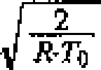
(4) , a velocidade de sida do jato adiabática é = ] (5) onde significam, além disso d bocal [m] diâmetro de bocal mL [kg/s] corrente de massa de gás pi [bar (abs)] pressão de gás antes do bocal(4), the adiabatic jet's velocity is =] (5) where, in addition, nozzle [m] nozzle diameter mL [kg / s] gas mass current pi [bar (abs)] pressure of gas before the nozzle
R [kJ/kgK] constante de gásR [kJ / kgK] gas constant
To [K] temperatura do gás antes do bocal k componente isentrópicoTo [K] gas temperature before the nozzle k isentropic component
Tmax coeficiente de descarga.Tmax discharge coefficient.
[00065] Quando as equações 2, 4 e 5 são usadas na equação 1, então obtém-se r = c, = ^^•^•^-[i-í#)'*1]<6) com[00065] When equations 2, 4 and 5 are used in equation 1, then r = c, = ^^ • ^ • ^ - [i-í #) '* 1 ] <6) with
Cj = 2^ eCj = 2 ^ e
ÍKmax ““ V x+1 V K+i ) onde adicionalmente significaÍKmax ““ V x + 1 V K + i) where additionally means
C3 constante.Constant C3.
Se, finalmente, t9 >If finally t9>
comwith

Petição 870190094873, de 23/09/2019, pág. 25/36Petition 870190094873, of 9/23/2019, p. 25/36
23/2623/26
C constante, então, depois da conversão, obtém-seConstant C, then, after conversion, you get
- arei — c =- the king - c =
J onde finalmente significa arei comprimento de jato relativoJ where r i means finally jet relative length
[00066] Por conseguinte, o comprimento do jato arei só é dependente da pressão de gás de moagem po, da relação de pressão pi/po e de k, mas não da temperatura do gás de moagem.[00066] Therefore, the length of the jet is only re i th dependent milling gas pressure, pressure ratio pi / n and k, but not of the milling gas temperature.
[00067] De testes (vide também Nied, R.: Strahlmahlung in der Fliexxbettgegenstrahlmühle; tiz 109 (1985)1, p. 23 ss) é conhecido que • para uma pressão de gás de moagem de po = 7 bar (abs) • uma relação de pressão de pi/po = 1,1/7 e • k = 1 m4 o comprimento do jato relativo arei fica = 20.[00067] From tests (see also Nied, R .: Strahlmahlung in der Fliexxbettgegenstrahlmühle; tiz 109 (1985) 1, p. 23 ss) it is known that • for a grinding gas pressure of po = 7 bar (abs) • a pressure ratio of pi / po = 1.1 / 7 and • k = 1 m4 the length of the jet relative to remainder = 20.
[00068] Com isso, pode ser calculado o valor da constante C em C = 9,922 (11).[00068] With this, the value of constant C can be calculated at C = 9.922 (11).
[00069] Na figura 4 está representada graficamente a relação entre a pressão de gás po antes do bocal e o comprimento de jato relativo arei na base da avaliação gráfica da equação 10, com C de acordo com a equação 11.[00069] Figure 4 shows the relationship between the gas pressure po before the nozzle and the jet length relative to re i on the basis of the graphical evaluation of equation 10, with C according to equation 11.
[00070] A invenção está representada apenas exemplificadamente por meio dos exemplos de modalidade na descrição e no desenho e não está limitada aos mesmos, mas abrange todas as variações, modificações, substituições e combinações, que o técnico pode extrair dos presentes documentos, particularmente no âmbito das exposições gerais na introdução desta descrição, bem como da descrição dos exemplos de modalidade e de suas representações no desenho e combinar os mesmos com seu conhecimento técnico, bem como do estado da técnica. Particularmente, todas as características e[00070] The invention is represented only as an example by means of the modality examples in the description and drawing and is not limited to them, but covers all variations, modifications, substitutions and combinations, which the technician can extract from these documents, particularly in the scope of the general exhibitions in the introduction of this description, as well as the description of the modality examples and their representations in the drawing and to combine them with their technical knowledge, as well as the state of the art. In particular, all the features and
Petição 870190094873, de 23/09/2019, pág. 26/36Petition 870190094873, of 9/23/2019, p. 26/36
24/26 possibilidades de configuração individuais da invenção e suas variantes de execução podem ser combinadas.24/26 individual configuration possibilities of the invention and its execution variants can be combined.
LISTAGEM DE REFERÊNCIAS moinho de jato carcaça cilíndrica câmara de moagem carregamento de material de moagem entrada de jato de moagem saída de produto separador a ar roda de separação abertura de entrada ou bocal de entrada ou bocal de entrada jato de moagem fonte de aquecimento fonte de aquecimento tubo de alimentação revestimento isolante de temperatura entrada saída centro da câmara de moagem dispositivo de reservatório ou produção dispositivos de tubulação bocal de saída carcaça de separação parte superior de carcaça parte inferior de carcaça flange periférico flange periférico articulaçãoREFERENCE LISTING jet mill cylindrical housing grinding chamber loading of grinding material grinding jet inlet product outlet air separator separating wheel inlet or inlet nozzle or inlet nozzle grinding jet heating source heating source supply pipe temperature insulating coating inlet outlet center of grinding chamber reservoir or production device piping devices outlet nozzle separation housing upper housing lower housing peripheral flange peripheral flange joint
Petição 870190094873, de 23/09/2019, pág. 27/36Petition 870190094873, of 9/23/2019, p. 27/36
25/26 seta carcaça de câmara de separação braços de suporte cone de descarga flange flange disco de cobertura disco de cobertura Pá eixo de roda de separação mancal giratório placas trabalhadas superiores placas trabalhadas inferiores parte terminal de carcaça bocal de carregamento de produto eixo de rotação câmara de saída placa de cobertura superior tampa removível braços de suporte carcaça anular cônica filtro de aspiração placa perfurada tubo de descarga de material fino cone defletor espiral de entrada de ar de separação descarga de material grosso flange flange zona de dispersão25/26 arrow separation chamber housing support arms discharge cone flange flange cover disc cover disc Shovel separating wheel shaft upper bearing plates lower worked plates lower worked plate housing end part product loading nozzle rotation axis chamber outlet top cover plate removable cover support arms conical annular housing suction filter perforated plate thin material discharge tube cone separator air inlet separator thick material discharge flange flange dispersion zone
Petição 870190094873, de 23/09/2019, pág. 28/36Petition 870190094873, of 9/23/2019, p. 28/36
26/26 flange trabalhados na borda interna (chanfrados) e revestimento tubo de proteção trocável tubo de proteção trocável saída/descarga de material fino coroa de pás26/26 flanges worked on the inner edge (chamfered) and coating exchangeable protective tube exchangeable protective tube outlet / discharge of fine material crown of blades
Claims (8)
Applications Claiming Priority (3)
| Application Number | Priority Date | Filing Date | Title |
|---|---|---|---|
| DE102006017472.0 | 2006-04-13 | ||
| DE102006017472A DE102006017472A1 (en) | 2006-04-13 | 2006-04-13 | Method for producing finest particles by means of a jet mill |
| PCT/DE2007/000649 WO2007118460A1 (en) | 2006-04-13 | 2007-04-13 | Method for the production of very fine particles by means of a jet mill |
Publications (2)
| Publication Number | Publication Date |
|---|---|
| BRPI0710652A2 BRPI0710652A2 (en) | 2011-08-23 |
| BRPI0710652B1 true BRPI0710652B1 (en) | 2020-05-19 |
Family
ID=38461131
Family Applications (1)
| Application Number | Title | Priority Date | Filing Date |
|---|---|---|---|
| BRPI0710652A BRPI0710652B1 (en) | 2006-04-13 | 2007-04-13 | jet mill |
Country Status (8)
| Country | Link |
|---|---|
| US (1) | US8177149B2 (en) |
| EP (1) | EP2004329B1 (en) |
| JP (1) | JP5463138B2 (en) |
| CN (1) | CN101421044B (en) |
| BR (1) | BRPI0710652B1 (en) |
| DE (1) | DE102006017472A1 (en) |
| ES (1) | ES2773730T3 (en) |
| WO (1) | WO2007118460A1 (en) |
Families Citing this family (15)
| Publication number | Priority date | Publication date | Assignee | Title |
|---|---|---|---|---|
| DE102006017472A1 (en) | 2006-04-13 | 2007-10-18 | Nied, Roland, Dr. Ing. | Method for producing finest particles by means of a jet mill |
| DE102006023193A1 (en) * | 2006-05-17 | 2007-11-22 | Nied, Roland, Dr.-Ing. | Method for producing finest particles by means of a jet mill |
| DE102006048864A1 (en) * | 2006-10-16 | 2008-04-17 | Roland Dr. Nied | Process for the production of finest particles and jet mill therefor and air classifier and operating method thereof |
| DE102009045116A1 (en) | 2009-09-29 | 2011-03-31 | Evonik Degussa Gmbh | Niederdruckvermahlungsverfahren |
| US20120325942A1 (en) * | 2011-06-27 | 2012-12-27 | General Electric Company | Jet milling of boron powder using inert gases to meet purity requirements |
| DE102013000426A1 (en) * | 2013-01-14 | 2014-07-17 | Roland Nied | Method for jet grinding and jet mill for it |
| CN103977870B (en) * | 2014-05-26 | 2016-03-30 | 北京航空航天大学 | Air-flow crushing stripping technology is adopted to prepare the method for Graphene presoma two-dimensional nano graphite powder |
| WO2016202320A1 (en) * | 2015-06-15 | 2016-12-22 | Netzsch Trockenmahltechnik Gmbh | Method for comminuting material to be ground and mill therefor |
| US10780443B2 (en) * | 2017-05-11 | 2020-09-22 | Roger Swensen | Method, system and apparatus for hard contaminate separation from a particulate |
| CN107213972B (en) * | 2017-05-17 | 2019-06-04 | 宁波拜尔玛生物科技有限公司 | Mannan prepared based on nanotechnology and its antitumor and antiviral application |
| DE102018120596A1 (en) * | 2018-08-23 | 2020-02-27 | Netzsch Trockenmahltechnik Gmbh | Method and device for removing difficult-to-grind particles from a spiral jet mill |
| KR102777240B1 (en) * | 2019-01-09 | 2025-03-07 | 큐웨이브 솔루션즈 인코포레이티드 | Method and system for jet milling |
| DE102020006724A1 (en) * | 2020-11-03 | 2022-05-05 | Netzsch Trockenmahltechnik Gmbh | Method of operation for a sifter and sifter for classification |
| DE102021002671A1 (en) | 2021-05-21 | 2022-11-24 | Hosokawa Alpine Aktiengesellschaft | Process for determining the optimum nozzle spacing in jet mills and grinding processes for producing the finest particles |
| US20260091903A1 (en) * | 2024-10-02 | 2026-04-02 | Weiler Engineering Inc. | Particulate matter containment system |
Family Cites Families (26)
| Publication number | Priority date | Publication date | Assignee | Title |
|---|---|---|---|---|
| US3877647A (en) * | 1973-05-30 | 1975-04-15 | Vladimir Ivanovich Gorobets | Jet mill |
| GB1481304A (en) | 1974-09-05 | 1977-07-27 | Boc International Ltd | Powder forming |
| DE2922438A1 (en) | 1979-06-01 | 1980-12-18 | Stiegler Karl Heinz | MACHINE FOR MACHINING A MOVING MATERIAL RAIL BY MEANS OF A MOVING WELDING TOOL |
| DE3140294C2 (en) * | 1981-10-10 | 1983-11-17 | Alpine Ag, 8900 Augsburg | Method and device for separating a material mixture into components of different grindability |
| EP0211117A3 (en) | 1985-08-02 | 1988-02-03 | Rmd Industries, Inc. | Method and apparatus for providing finely divided powder |
| DE3620440A1 (en) | 1986-06-18 | 1987-12-23 | Indutec Industrietechnik Gmbh | Two-stage opposing jet comminution method operated under pressure for enlarging the surface area of fine grained to granular bulk materials |
| DE3825469A1 (en) * | 1988-07-27 | 1990-02-01 | Basf Ag | METHOD FOR DISPERSION, CRUSHING OR DESAGGLOMERATION AND SIGHTING OF SOLIDS |
| US5252110A (en) * | 1990-08-01 | 1993-10-12 | Roland Nied | Preferably vertical air separator |
| IT1248066B (en) * | 1991-06-17 | 1995-01-05 | Italcementi Spa | DYNAMIC SEPARATOR FOR POWDERED MATERIALS, IN PARTICULAR CEMENT AND PLANT THAT INCLUDES IT |
| CN2111798U (en) * | 1991-12-10 | 1992-08-05 | 武汉工业大学 | Pneumatic jet powders classifier |
| DE4243438C2 (en) * | 1992-12-22 | 1996-06-05 | Hosokawa Alpine Ag | Method and device for fluid bed jet grinding |
| JPH06271309A (en) * | 1993-03-22 | 1994-09-27 | Sumitomo Sitix Corp | Method for crushing polycrystalline silicon |
| CN2180331Y (en) * | 1994-05-26 | 1994-10-26 | 西安秦岭超细粉厂 | Ultramicro air flow crusher with fluidized bed structure crushing chamber |
| JP2953985B2 (en) * | 1995-04-20 | 1999-09-27 | 松下電子工業株式会社 | Sandblasting device and method for manufacturing gas discharge type display device |
| US5899396A (en) * | 1995-09-04 | 1999-05-04 | Nied; Roland | Air separator and single-rotor air separator mill with such an air separator |
| DE19824062A1 (en) * | 1998-05-29 | 1999-12-02 | Roland Nied | Grinding process using a jet mill |
| JP2000015126A (en) * | 1998-06-29 | 2000-01-18 | Minolta Co Ltd | Fluidized-bed jet crusher |
| JP3901862B2 (en) * | 1998-12-21 | 2007-04-04 | 信越半導体株式会社 | Wafer bonding method |
| US6398139B1 (en) * | 1999-08-23 | 2002-06-04 | Roland Nied | Process for fluidized-bed jet milling, device for carrying out this process and unit with such a device for carrying out this process |
| US6383706B1 (en) * | 2000-07-13 | 2002-05-07 | Xerox Corporation | Particulate smoothing process |
| JP2005046758A (en) * | 2003-07-30 | 2005-02-24 | Daifuku Kogyo Kk | Rubber tire crushing device and its method |
| JP2005213062A (en) * | 2004-01-27 | 2005-08-11 | Toyota Motor Corp | Granulated slag manufacturing method and granulated slag manufacturing apparatus |
| EP1952334A4 (en) * | 2005-11-18 | 2011-06-08 | Chicago Mercantile Exchange | Detection of intra-firm matching and response thereto |
| DE102006017472A1 (en) | 2006-04-13 | 2007-10-18 | Nied, Roland, Dr. Ing. | Method for producing finest particles by means of a jet mill |
| DE102006023193A1 (en) * | 2006-05-17 | 2007-11-22 | Nied, Roland, Dr.-Ing. | Method for producing finest particles by means of a jet mill |
| US7713614B2 (en) * | 2006-09-19 | 2010-05-11 | Kuraray Co., Ltd. | Resin composition and multilayer structure |
-
2006
- 2006-04-13 DE DE102006017472A patent/DE102006017472A1/en not_active Withdrawn
-
2007
- 2007-04-13 BR BRPI0710652A patent/BRPI0710652B1/en active IP Right Grant
- 2007-04-13 US US12/296,761 patent/US8177149B2/en active Active
- 2007-04-13 CN CN2007800131720A patent/CN101421044B/en active Active
- 2007-04-13 EP EP07722207.3A patent/EP2004329B1/en active Active
- 2007-04-13 ES ES07722207T patent/ES2773730T3/en active Active
- 2007-04-13 JP JP2009504565A patent/JP5463138B2/en active Active
- 2007-04-13 WO PCT/DE2007/000649 patent/WO2007118460A1/en not_active Ceased
Also Published As
| Publication number | Publication date |
|---|---|
| US8177149B2 (en) | 2012-05-15 |
| BRPI0710652A2 (en) | 2011-08-23 |
| EP2004329B1 (en) | 2019-11-27 |
| CN101421044A (en) | 2009-04-29 |
| WO2007118460A1 (en) | 2007-10-25 |
| US20100065668A1 (en) | 2010-03-18 |
| DE102006017472A1 (en) | 2007-10-18 |
| EP2004329A1 (en) | 2008-12-24 |
| JP5463138B2 (en) | 2014-04-09 |
| CN101421044B (en) | 2012-11-28 |
| JP2009533207A (en) | 2009-09-17 |
| ES2773730T3 (en) | 2020-07-14 |
Similar Documents
| Publication | Publication Date | Title |
|---|---|---|
| BRPI0710652B1 (en) | jet mill | |
| US8074907B2 (en) | Method for generating finest particles and jet mill therefor as well as classifier and operating method thereof | |
| BRPI0717607B1 (en) | PROCESS FOR THE PRODUCTION OF FINISH PARTICULES BY A JET MILL | |
| JP5200168B2 (en) | Method for classifying pulverized product-fluid mixture and pulverizing classifier | |
| JP5432707B2 (en) | Method for producing very fine particles using a jet mill | |
| JP2011530404A5 (en) | Method for classifying pulverized product-fluid mixture and pulverizing classifier | |
| CN206642897U (en) | The used manifold type mill separator of rotation | |
| US6398139B1 (en) | Process for fluidized-bed jet milling, device for carrying out this process and unit with such a device for carrying out this process | |
| CN103752426A (en) | Online hydrocyclone regulating device based on overflow pipe | |
| CA2680393C (en) | Apparatus and method for sifting feedstock | |
| JP3326188B2 (en) | Air classifier | |
| CN206643008U (en) | Mill separator | |
| JP4753387B2 (en) | Airflow classifier | |
| CN106622617B (en) | Tailing separator is used in binary channels rotation | |
| JP2000343040A (en) | Centrifugal selector | |
| CN104190621B (en) | Wind sweeping type moving and motionless combination efficient dust separator | |
| JP3211420B2 (en) | Classifier | |
| JPS5919738B2 (en) | Composite vane rotor separator for roll mills | |
| JPH02187179A (en) | Separator | |
| US2914172A (en) | Pneumatic classifier system |
Legal Events
| Date | Code | Title | Description |
|---|---|---|---|
| B06F | Objections, documents and/or translations needed after an examination request according [chapter 6.6 patent gazette] | ||
| B06A | Patent application procedure suspended [chapter 6.1 patent gazette] | ||
| B09A | Decision: intention to grant [chapter 9.1 patent gazette] | ||
| B16A | Patent or certificate of addition of invention granted [chapter 16.1 patent gazette] |
Free format text: PRAZO DE VALIDADE: 10 (DEZ) ANOS CONTADOS A PARTIR DE 19/05/2020, OBSERVADAS AS CONDICOES LEGAIS. |