BRPI0801488B1 - COVER FOR MOTONE TYPE VEHICLE RADIATOR AND MOTONE TYPE VEHICLE PROVIDED WITH THE SAME - Google Patents
COVER FOR MOTONE TYPE VEHICLE RADIATOR AND MOTONE TYPE VEHICLE PROVIDED WITH THE SAME Download PDFInfo
- Publication number
- BRPI0801488B1 BRPI0801488B1 BRPI0801488-4A BRPI0801488A BRPI0801488B1 BR PI0801488 B1 BRPI0801488 B1 BR PI0801488B1 BR PI0801488 A BRPI0801488 A BR PI0801488A BR PI0801488 B1 BRPI0801488 B1 BR PI0801488B1
- Authority
- BR
- Brazil
- Prior art keywords
- radiator
- ventilation hole
- central surface
- scooter
- type vehicle
- Prior art date
Links
Classifications
-
- F—MECHANICAL ENGINEERING; LIGHTING; HEATING; WEAPONS; BLASTING
- F01—MACHINES OR ENGINES IN GENERAL; ENGINE PLANTS IN GENERAL; STEAM ENGINES
- F01P—COOLING OF MACHINES OR ENGINES IN GENERAL; COOLING OF INTERNAL-COMBUSTION ENGINES
- F01P11/00—Component parts, details, or accessories not provided for in, or of interest apart from, groups F01P1/00 - F01P9/00
- F01P11/10—Guiding or ducting cooling-air, to, or from, liquid-to-air heat exchangers
-
- B—PERFORMING OPERATIONS; TRANSPORTING
- B62—LAND VEHICLES FOR TRAVELLING OTHERWISE THAN ON RAILS
- B62M—RIDER PROPULSION OF WHEELED VEHICLES OR SLEDGES; POWERED PROPULSION OF SLEDGES OR SINGLE-TRACK CYCLES; TRANSMISSIONS SPECIALLY ADAPTED FOR SUCH VEHICLES
- B62M7/00—Motorcycles characterised by position of motor or engine
- B62M7/12—Motorcycles characterised by position of motor or engine with the engine beside or within the driven wheel
-
- B—PERFORMING OPERATIONS; TRANSPORTING
- B62—LAND VEHICLES FOR TRAVELLING OTHERWISE THAN ON RAILS
- B62K—CYCLES; CYCLE FRAMES; CYCLE STEERING DEVICES; RIDER-OPERATED TERMINAL CONTROLS SPECIALLY ADAPTED FOR CYCLES; CYCLE AXLE SUSPENSIONS; CYCLE SIDECARS, FORECARS, OR THE LIKE
- B62K2202/00—Motorised scooters
-
- F—MECHANICAL ENGINEERING; LIGHTING; HEATING; WEAPONS; BLASTING
- F01—MACHINES OR ENGINES IN GENERAL; ENGINE PLANTS IN GENERAL; STEAM ENGINES
- F01P—COOLING OF MACHINES OR ENGINES IN GENERAL; COOLING OF INTERNAL-COMBUSTION ENGINES
- F01P2050/00—Applications
- F01P2050/16—Motor-cycles
-
- F—MECHANICAL ENGINEERING; LIGHTING; HEATING; WEAPONS; BLASTING
- F01—MACHINES OR ENGINES IN GENERAL; ENGINE PLANTS IN GENERAL; STEAM ENGINES
- F01P—COOLING OF MACHINES OR ENGINES IN GENERAL; COOLING OF INTERNAL-COMBUSTION ENGINES
- F01P5/00—Pumping cooling-air or liquid coolants
- F01P5/02—Pumping cooling-air; Arrangements of cooling-air pumps, e.g. fans or blowers
- F01P5/06—Guiding or ducting air to, or from, ducted fans
Landscapes
- Engineering & Computer Science (AREA)
- Chemical & Material Sciences (AREA)
- Combustion & Propulsion (AREA)
- Mechanical Engineering (AREA)
- Transportation (AREA)
- General Engineering & Computer Science (AREA)
- Cooling, Air Intake And Gas Exhaust, And Fuel Tank Arrangements In Propulsion Units (AREA)
- Automatic Cycles, And Cycles In General (AREA)
Abstract
cobertura para radiador de veículo do tipo motoneta e veículo do tipo motoneta provido com a mesma. uma cobertura de radiador (cobertura de radiador de um veículo do tipo motoneta) é disposta em relação a um radiador, do qual uma superfície central está disposta na direção da seta r (lateralmente em relação ao veículo), de maneira a cobrir um lado externo (um lado na direção da seta r) da superfície central, e está provida com uma pluralidade de orifícios de ventilação (oríficios de ventilação fron- tais, orifícios de ventilação posteriores e oríficios de ventilação inferiores), que são formados de modo a ficarem opostos à superfície central e respectivamente abertos em diferentes direções.radiator cover for scooter type vehicle and scooter type vehicle provided with it. a radiator hood (radiator hood of a scooter type vehicle) is disposed relative to a radiator, of which a central surface is arranged in the direction of the arrow r (laterally relative to the vehicle) so as to cover an outside (one side in the direction of arrow r) of the central surface, and is provided with a plurality of ventilation holes (front ventilation holes, rear ventilation holes and bottom ventilation holes), which are formed so that they are opposite each other. central surface and respectively open in different directions.
Description
(54) Título: COBERTURA PARA RADIADOR DE VEÍCULO DO TIPO MOTONETA E VEÍCULO DO TIPO MOTONETA PROVIDO COM A MESMA (51) Int.CI.: B62J 31/00 (30) Prioridade Unionista: 17/05/2007 JP 2007-131630 (73) Titular(es): YAMAHA HATSUDOKI KABUSHIKI KAISHA (72) Inventor(es): NOBUYUKI MIYOSHI; SATOSHI KAWAKAMI(54) Title: COVERAGE FOR MOTORCYCLE VEHICLE RADIATOR AND MOTORCYCLE VEHICLE PROVIDED WITH THE SAME (51) Int.CI .: B62J 31/00 (30) Unionist Priority: 17/05/2007 JP 2007-131630 ( 73) Holder (s): YAMAHA HATSUDOKI KABUSHIKI KAISHA (72) Inventor (s): NOBUYUKI MIYOSHI; SATOSHI KAWAKAMI
Cobertura para Radiador de Veículo do Tipo Motoneta e Veículo do tipo Motoneta Provido com a Mesma presente pedido reivindica a prioridade do Pedido de Patente japonês No 2007 - 131 630, depositado em 17 de maio de 2007.Coverage for Radiator Vehicle Type Scooter and Vehicle Type Scooter Provided with the same present application claims the priority of Japanese Patent Application No. 2007 - 131 630, filed on May 17, 2007.
Embasamento da InvençãoBasis of the Invention
1. Campo da Invenção.1. Field of the Invention.
A presente invenção está relacionada a uma cobertura de radiador de um veículo do tipo motoneta e a um veí10 culo.do tipo motoneta provido com a mesma; mais especificamente a uma cobertura de radiador de um veículo do tipo motoneta, o qual inclui um orifício de ventilação, e a um veículo do tipo motoneta provido com a mesma.The present invention relates to a radiator cover of a scooter-type vehicle and a scooter-type vehicle provided with it; more specifically to a radiator hood of a scooter-type vehicle, which includes a ventilation hole, and to a scooter-type vehicle provided with it.
2. Descrição da Técnica Correlacionada.2. Description of the Correlated Technique.
Foram propostos veículo providos com uma grelha (cobertura de radiador) do tipo de veículos de pequeno porte conhecidos como motonetas (biciclos) (ver, por exemplo, o registro de modelo de utilidade japonês No 2 576 872). O registro de modelo de utilidade japonês No 2 576 872 descreveVehicles equipped with a grille (radiator cover) of the type of small vehicles known as scooters (bicycles) have been proposed (see, for example, Japanese utility model registration No. 2 576 872). Japanese utility model registration No. 2 576 872 describes
2.0 um radiador possuindo uma superfície central disposta de modo a apresentar um ângulo predeterminado em relação a direção de movimento em lugar de lateralmente ao corpo do veículo, e uma grelha disposta por fora da superfície central do radiador. A grelha do veículo' do tipo motoneta de pequeno porte é conformada com uma pluralidade de membros em forma de placa de modo a apresentarem um ângulo predeterminado em relação à direção de movimento em lugar de lateralmente ao corpo do veículo; e uma pluralidade de portas ou aberturas de entrada / admissão é respectivamente formada entre a pluralidade de membros em forma de placas de modo a se abrirem substancialmente em uma só direção.2.0 a radiator having a central surface arranged so as to have a predetermined angle in relation to the direction of movement instead of laterally to the vehicle body, and a grid arranged outside the central surface of the radiator. The vehicle grid of the small scooter type is formed with a plurality of plate-shaped members so as to present a predetermined angle in relation to the direction of movement instead of laterally to the vehicle body; and a plurality of entry / inlet doors or openings are respectively formed between the plurality of plate-shaped members so as to open substantially in one direction.
No entanto, com a grelha (cobertura do radiador) do veiculo de pequeno porte do tipo motoneta descrita no registro de modelo de utilidade japonês No 2 576 872, a pluralidade de aberturas de entrada ficam abertas substancialmente em uma só direção, de forma que apenas o ar de um dos lados penetra.. Portanto, surge um problema que torna difícil a melhoria da eficiência de tomada de .ar para refrigeração de um radiador montado no veículo de pequeno porte do tipo motoneta.However, with the grille (radiator cover) of the small motor scooter type described in the Japanese utility model registration No. 2 576 872, the plurality of entry openings are open substantially in one direction, so that only the air from one side enters. Therefore, a problem arises that makes it difficult to improve the air intake efficiency for cooling a radiator mounted on a small scooter-type vehicle.
Resumo da InvençãoSummary of the Invention
O objetivo da invenção consiste em solucionar os problemas acima descritos através do provimento de uma cobertura de radiador para um veículo do tipo motoneta capaz de melhorar a eficiência de tomada de ar para refrigeração de um radiador; bem como de um veículo tipo motoneta provido com a mesma.The aim of the invention is to solve the problems described above by providing a radiator cover for a scooter-type vehicle capable of improving the air intake efficiency for cooling a radiator; as well as a scooter-type vehicle fitted with it.
Uma cobertura de radiador de um veículo do tipo motoneta em um primeiro aspecto da invenção compreende uma pluralidade de orifícios de ventilação dispostos em relação a um radiador com uma superfície central disposta lateralmente em relação ao veículo de modo a cobrir um lado externo da superfície central, voltados para a superfície central e respectivamente abertos para diferentes direções.A radiator cover of a scooter-type vehicle in a first aspect of the invention comprises a plurality of ventilation holes arranged in relation to a radiator with a central surface disposed laterally in relation to the vehicle in order to cover an external side of the central surface, facing the central surface and respectively opened in different directions.
Com a cobertura de radiador de um veículo do tipo motoneta no primeiro aspecto, é provida uma pluralidade deWith the radiator cover of a scooter-type vehicle in the first aspect, a plurality of

orifícios de ventilação para cobrir um lado externo de uma (Q superfície central de um radiador, com a superfície central disposta lateralmente em relação ao veículo e para estar respectivamente aberta em diferentes direções, pelo que a pluralidade de orifícios de ventilação respectivamente abertos para diferentes direções permitem a tomada de ar para refrigeração do radiador em uma pluralidade de direções. Conseqüentemente, é possível me^lhorar a eficiência de tomada de ar para a refrigeração do radiador.ventilation holes to cover an external side of a (Q central surface of a radiator, with the central surface arranged laterally in relation to the vehicle and to be respectively open in different directions, so the plurality of ventilation holes respectively opened for different directions they allow air intake for cooling the radiator in a plurality of directions, consequently it is possible to improve the air intake efficiency for cooling the radiator.
Na cobertura de radiador de um veículo do tipo motoneta no primeiro aspecto, os orifícios de ventilação compreendem de preferência um primeiro orifício de ventilação aberto para uma direção do movimento do veículo, e um segundo orifício de ventilação aberto para uma direção oposta à direção do movimento. Com tal estrutura, é possível a pronta e fácil tomada de ar para refrigeração do radiador, tanto na direção de movimento como em uma direção oposta à direção de movimento.In the radiator cover of a scooter-type vehicle in the first aspect, the ventilation holes preferably comprise a first ventilation hole open for one direction of movement of the vehicle, and a second ventilation hole open for a direction opposite to the direction of movement . With such a structure, ready and easy air intake for cooling the radiator is possible, both in the direction of movement and in a direction opposite to the direction of movement.
A cobertura de radiador de um veículo do tipo motoneta no primeiro aspecto de preferência compreende também um membro de chicana ou defletor provido em um lado do radiador para direcionar o ar, que é tomado a partir da pluralidade de orifícios de ventilação para refrigerar o radiador, para a superfície central do radiador. Com tal estrutura, é possível impedir que o ar, que é tomado a partir da pluralidade de orifícios de ventilação para refrigerar o radiador, passe a outras partes que não a superfície central do radiador, de forma a melhorar a eficiência de refrigeração do ra4 diador.The radiator cover of a scooter-type vehicle in the first aspect preferably also comprises a baffle or deflector member provided on one side of the radiator to direct the air, which is taken from the plurality of ventilation holes to cool the radiator, to the central surface of the radiator. With such a structure, it is possible to prevent the air, which is taken from the plurality of ventilation holes to cool the radiator, from passing to parts other than the central surface of the radiator, in order to improve the cooling efficiency of the radiator. .
Na cobertura de radiador de um veículo do tipo motoneta no primeiro aspecto, os orifícios de ventilação compreendem de preferência um primeiro orifício de ventilação aberto para a direção do movimento para tomar pelo menos uma parte do ar do movimento, e um segundo orifício de ventilação aberto para a direção oposta à direção do movimento para tomar o vento de entrada de uma ventoinha de entrada ou admissão' disposta sobre uma superfície oposta à superfície central do radiador. Com tal estrutura, é possível facilmente levar um ar do movimento a entrar a partir do primeiro orifício de ventilação para tomada de ar para refrigeração do radiador e levar um ar de entrada da ventoinha de entrada a entrar a partir do segundo orifício de ventilação para tomada de ar para refrigeração do radiador.In the radiator cover of a scooter-type vehicle in the first aspect, the ventilation holes preferably comprise a first open ventilation hole for the direction of movement to take at least part of the air from the movement, and a second open ventilation hole. in the direction opposite to the direction of movement to take the incoming wind from an inlet or intake fan 'arranged on a surface opposite the central surface of the radiator. With such a structure, it is possible to easily bring air from the movement in from the first ventilation hole for cooling air from the radiator and take air from the intake fan in from the second ventilation hole to the outlet air for cooling the radiator.
Na cobertura de radiador de um veículo do tipo motoneta, em que são providos os orifícios de ventilação compreendendo o primeiro orifício de ventilação e o segundo orifício de ventilação, de preferência o primeiro orifício de ventilação é provido de modo a estar aberto para uma direção inclinada em um ângulo predeterminado em relação à largura do veículo na direção de percurso, enquanto o segundo orifício de ventilação é provido de modo a estar aberto para uma direção inclinada em um ângulo predeterminado em relação à largura do veículo na direção oposta àquela de percurso. Por meio de tal estrutura, é possível levar um, vento devido ao movimento a fluir prontamente a partir do primeiro orifício de ventilação aberto para uma direção inclinada em um ânguloIn the radiator cover of a scooter-type vehicle, where the ventilation holes comprising the first ventilation hole and the second ventilation hole are provided, preferably the first ventilation hole is provided so that it is open to an inclined direction at a predetermined angle to the width of the vehicle in the direction of travel, while the second ventilation hole is provided so as to be open to a direction inclined at a predetermined angle to the width of the vehicle in the direction opposite to that of travel. Through such a structure, it is possible to take a wind due to the movement to flow readily from the first open ventilation hole to an inclined direction at an angle

ao predeterminado em relação à largura do veículo na direção do movimento, e levar um vento devido à ventoinha de entrada a fluir prontamente a partir do segundo orifício de ventilação em uma direção inclinada em um ângulo predeterminado em relação à largura do veículo em uma direção oposta àquela da direção do movimento.to the predetermined in relation to the width of the vehicle in the direction of movement, and to bring a wind due to the inlet fan to flow readily from the second ventilation hole in a direction inclined at a predetermined angle in relation to the width of the vehicle in an opposite direction that of the direction of movement.
De preferência, a cobertura de radiador de um veículo. do tipo motoneta, em que são providos de ventilação compreendendo o primeiro orifício de ventilação e o segundo orifício de ventilação, compreende também uma pluralidade de primeiros membros em forma de placa providos sobre o primeiro orifício de ventilação e uma pluralidade de segundos membros em forma de placa providos sobre o segundo orifício de ventilação, estando a pluralidade de primeiros membros em forma de placa dispostos em um ângulo de inclinação menor em relação à superfície central do que a pluralidade de segundos membros em forma de placa. Por meio de tal estrutura, é inibida a entrada de respingos de lama ou similares provenientes da direção de movimento, em comparação ao segundo orifício de ventilação aberto em uma direção oposta à direção de movimento.Preferably, a vehicle's radiator cover. scooter type, in which ventilation is provided comprising the first ventilation hole and the second ventilation hole, it also comprises a plurality of first plate-shaped members provided over the first ventilation hole and a plurality of second shaped members plate provided over the second ventilation hole, the plurality of first plate-shaped members being disposed at a lower angle of inclination with respect to the central surface than the plurality of second plate-shaped members. Through such a structure, the entry of mud or similar splashes from the direction of movement is inhibited, in comparison to the second ventilation hole opened in a direction opposite to the direction of movement.
Na cobertura de radiador de um veículo do tipo motoneta, em que a pluralidade de primeiros membros em forma de placa é provida sobre o primeiro orifício de ventilação, de preferência a pluralidade de primeiros membros em forma de placa estão respectivamente dispostos de modo a não se sobrepor uns aos outros quando observados em proj eção. Por meio de tal estrutura, é possível impedir que o fluxo de en6 trada do vento devido ao movimento seja obstruída, inibindo porém que lama e similares penetrem através do primeiro orifício de ventilação.In the radiator cover of a scooter-type vehicle, where the plurality of first plate-like members is provided over the first ventilation hole, preferably the plurality of first plate-like members are respectively arranged so as not to overlap each other when viewed in projection. Through this structure, it is possible to prevent the flow of incoming wind due to movement to be obstructed, however inhibiting mud and the like from penetrating through the first ventilation hole.
A cobertura de radiador de um veículo do tipo motoneta, em que são providos os orifícios de ventilação compreendendo o primeiro orifício de ventilação e o segundo orifício de ventilação, de preferência compreende. também uma parte de parede provida abaixo do segundo orifício de ventilação, através do qual é tomado o ar da ventoinha de entrada, para cobrir uma parte inferior da superfície central do radiador, os orifícios de ventilação compreendendo também um terceiro orifício de ventilação provido na parte de parede aberto em uma direção pela qual pelo menos uma parte do vento do movimento possa ser tomada. Por meio de tal estrutura, o terceiro orifício de ventilação, além do primeiro orifício de ventilação, permite a entrada do vento do movimento, o que possibilita uma melhoria adicional da eficiência de tomada .The radiator cover of a scooter-type vehicle, in which the ventilation holes comprising the first ventilation hole and the second ventilation hole are preferably provided. also a part of the wall provided below the second ventilation hole, through which air is taken from the intake fan, to cover a lower part of the central surface of the radiator, the ventilation holes also comprising a third ventilation hole provided in the part wall open in a direction by which at least part of the movement wind can be taken. Through this structure, the third ventilation hole, in addition to the first ventilation hole, allows the movement wind to enter, which allows for a further improvement in the shooting efficiency.
Na cobertura de radiador de um veículo do tipo motoneta, em que são providos os orifícios de ventilação compreendendo o terceiro orifício de ventilação, de preferência o primeiro orifício de ventilação está disposto de forma a ficar voltado para uma parte da superfície central na direção do movimento, o segundo orifício de ventilação está disposto de forma a ficar voltado para uma parte de uma porção superior da superfície central em uma direção oposta à direção de movimento, e o terceiro orifício de ventilação está disposto de forma a ficar voltado para uma parte de uma por7In the radiator cover of a scooter-type vehicle, in which the ventilation holes comprising the third ventilation hole are provided, preferably the first ventilation hole is arranged so that it faces a part of the central surface in the direction of movement , the second ventilation hole is arranged so that it faces a part of an upper portion of the central surface in a direction opposite to the direction of movement, and the third ventilation hole is arranged so that it faces a part of a por7

ção inferior da superfície central em uma direção oposta à direção do movimento. Por meio de tal estrutura, o primeiro orifício de ventilação permite a tomada de ar para refrigeração de um lado da superfície central na direção do movimento, o segundo orifício de ventilação permite a tomada de ar para refrigeração de uma parte da porção superior da superfície central em um lado oposto à direção do movimento, e o terceiro orifício de ventilação permite a tomada de ar para refrigeração de uma parte da porção inferior da superfície central em uma direção oposta à direção do movimento.lower part of the central surface in a direction opposite to the direction of movement. By means of such a structure, the first ventilation hole allows the intake of cooling air from one side of the central surface in the direction of movement, the second ventilation hole allows the intake of cooling air from a part of the upper portion of the central surface. on one side opposite to the direction of movement, and the third ventilation hole allows the intake of air for cooling part of the lower portion of the central surface in a direction opposite to the direction of movement.
Na cobertura de radiador de um veículo do tipo motoneta, em que são providos os orifícios de ventilação compreendendo o terceiro orifício de ventilação, de preferência o terceiro orifício de ventilação é conformado de modo a se estender obliquamente para baixo na direção do movimento. Por meio de tal estrutura, o terceiro orifício de ventilação permite que o ar devido ao movimento seja prontamente levado para baixo da superfície central do radiador, o qual é provido de modo a estar voltado para a cobertura de radiador.In the radiator cover of a scooter-type vehicle, where the ventilation holes comprising the third ventilation hole are provided, preferably the third ventilation hole is shaped so that it extends obliquely downward in the direction of movement. By means of such a structure, the third ventilation hole allows air due to movement to be readily taken down from the central surface of the radiator, which is provided so that it faces the radiator cover.
Na cobertura de radiador de um veículo do tipo motoneta, em que são providos os orifícios de ventilação compreendendo o terceiro orifício de ventilação, de preferência é também provido um membro de chicana sobre um lado da parte de parede em direção ao radiador para levar um ar do movimento, o qual é tomado a partir do primeiro orifício de ventilação e do. terceiro orifício de ventilação, para a parte inferior da superfície central do radiador. Por meio de tal estrutura, a parte de chicana pode impedir que o ar de movi8 mento, que flui a partir do terceiro orificio de ventilação, passe para trás, de forma a que o ar do movimento que flui a partir do terceiro orificio de ventilação possa ser eficientemente levado à parte inferior da superfície central do radiador.In the radiator cover of a scooter-type vehicle, where the ventilation holes comprising the third ventilation hole are provided, preferably a baffle member is also provided on one side of the wall part towards the radiator to bring air of the movement, which is taken from the first ventilation hole and the. third ventilation hole, to the bottom of the central surface of the radiator. By means of such a structure, the baffle part can prevent the movement air, which flows from the third ventilation hole, to pass backwards, so that the movement air flowing from the third ventilation hole can be efficiently driven to the bottom of the central radiator surface.
A cobertura de radiador de um veiculo do tipo motoneta, em que são providos os orifícios de ventilação compreendendo o primeiro orifício de ventilação e o segundo orifício de ventilação, de preferência compreende também uma parte de suporte ou viga provida entre o primeiro orifício de ventilação e o segundo orifício de ventilação para dividir o primeiro orifício de ventilação e o segundo orifício de ventilação. Por meio de tal estrutura, é possível melhorar a resistência mecânica contra um impacto externo.The radiator cover of a scooter-type vehicle, in which ventilation holes are provided comprising the first ventilation hole and the second ventilation hole, preferably also comprises a support part or beam provided between the first ventilation hole and the second ventilation hole to divide the first ventilation hole and the second ventilation hole. Through such a structure, it is possible to improve the mechanical resistance against an external impact.
De preferência, neste caso, a parte de viga é conformada de modo a se projetar para a frente em uma direção oposta à superfície central do radiador. Por meio de tal estrutura, é possível aumentar um espaço entre a superfície central do radiador e a superfície posterior da cobertura de radiador, de forma a que possa ser transferido o ar tomado para o interior do espaço entre a superfície central do radiador e a superfície posterior da cobertura de radiador. Desse modo, o ar tomado pode ser distribuído por toda a superfície central do radiador, de forma a possibilitar a melhoria da eficiência de refrigeração do radiador.Preferably, in this case, the beam part is shaped so that it projects forward in a direction opposite to the central surface of the radiator. By means of this structure, it is possible to increase a space between the central surface of the radiator and the rear surface of the radiator cover, so that the air taken into the space between the central surface of the radiator and the surface can be transferred. back of the radiator cover. In this way, the air taken in can be distributed throughout the central surface of the radiator, in order to improve the cooling efficiency of the radiator.
De preferência, a cobertura de radiador de um veículo do tipo motoneta no primeiro aspecto compreende também uma parte de cobertura de tampa, que cobre uma tampa de ra-Preferably, the radiator cover of a scooter-type vehicle in the first aspect also comprises a cap cover part, which covers a radiator cap.


diador do radiador. Por meio de tal estrutura, é possível proteger facilmente a tampa de radiador do radiador.radiator fan. By means of such a structure, it is possible to easily protect the radiator cap of the radiator.
veículo do tipo motoneta em um segundo aspecto da invenção compreende um radiador com uma superfície cen5 trai disposta lateralmente ao veículo; e uma cobertura de radiador disposta de modo a cobrir um lado externo da superfície central do radiador e compreendendo uma pluralidade de orifícios de ventilação conformados de modo a ficarem voltados para a superfície central e, respectivamente, abertos para diferentes direções. Por meio de tal estrutura, é possível se obter um veículo do tipo motoneta compreendendo uma cobertura de radiador por meio da qual pode ser melhorada a eficiência de tomada de ar para refrigeração de um radiador.A scooter-type vehicle in a second aspect of the invention comprises a radiator with a central surface arranged laterally to the vehicle; and a radiator cover arranged to cover an external side of the central surface of the radiator and comprising a plurality of ventilation holes shaped to face the central surface and, respectively, opened in different directions. Through such a structure, it is possible to obtain a scooter-type vehicle comprising a radiator cover by means of which the efficiency of air intake for cooling a radiator can be improved.
Breve Descrição dos DesenhosBrief Description of Drawings
A Figura 1 é uma vista lateral mostrando toda a estrutura de uma motocicleta de acordo com uma modalidade da invenção.Figure 1 is a side view showing the entire structure of a motorcycle according to an embodiment of the invention.
A .Figura 2 é uma vista' em corte ilustrando a estrutura de uma periferia de um radiador da motocicleta de acordo com a modalidade da Figura 1.Figure 2 is a cross-sectional view illustrating the structure of a motorcycle radiator periphery according to the embodiment of Figure 1.
A Figura 3 é uma vista em perspectiva ilustrando a estrutura de uma cobertura de radiador da motocicleta de acordo com a modalidade da Figura 1.Figure 3 is a perspective view illustrating the structure of a motorcycle radiator cap according to the embodiment of Figure 1.
A Figura 4 é uma vista frontal ilustrando a' estru25 tura da cobertura de radiador da motocicleta de acordo com a modalidade da Figura 1.Figure 4 is a front view illustrating the structure of the motorcycle radiator cover according to the embodiment of Figure 1.
A Figura 5 é um corte tomado ao longo da linha .100-100 da Figura 4.Figure 5 is a section taken along the .100-100 line in Figure 4.

A Figura 6 é um corte tomado ao longo da linha 200-200 da Figura 4.Figure 6 is a section taken along line 200-200 of Figure 4.
A Figura 7 é uma vista em perspectiva ilustrando a estrutura da cobertura de radiador da motocicleta de acordo com a modalidade da Figura 1.Figure 7 is a perspective view illustrating the structure of the motorcycle's radiator cover according to the embodiment of Figure 1.
A Figura 8 é uma vista posterior ilustrando a estrutura da cobertura de radiador da motocicleta de . acordo com a modalidade da Figura 1.; eFigure 8 is a rear view illustrating the structure of the motorcycle radiator hood. according to the modality of Figure 1 .; and
A Figura 9 é uma vista em projeção ilustrando a estrutura da cobertura de radiador da motocicleta de acordo com a modalidade da Figura 1.Figure 9 is a projected view illustrating the structure of the motorcycle's radiator cover according to the modality of Figure 1.
Descrição Detalhada das Modalidades PreferidasDetailed Description of Preferred Modalities
A seguir, será descrita uma modalidade da invenção com referência aos desenhos.In the following, an embodiment of the invention will be described with reference to the drawings.
A Figura 1 é uma vista lateral mostrando toda a estrutura de uma motocicleta de acordo com uma modalidade da invenção. As Figuras 2 a 9 são vistas que ilustram uma estrutura da periferia de uma cobertura de radiador da motocicleta de acordo com a modalidade apresentada na Figura. 1. Além disso, a modalidade será descrita com referência a uma motocicleta do tipo motoneta ou scooter como exemplo de um veiculo do tipo motoneta / biciclo da invenção. Nos desenhos, FWD indica a frente em uma direção de movimento ou percurso de uma motocicleta. A estrutura de uma motocicleta 1 de acordo com uma modalidade da invenção será descrita em detalhes com referência às Figuras 1 a 9.Figure 1 is a side view showing the entire structure of a motorcycle according to an embodiment of the invention. Figures 2 to 9 are views that illustrate a structure of the periphery of a motorcycle radiator cover according to the modality shown in the Figure. 1. In addition, the modality will be described with reference to a scooter-type motorcycle or scooter as an example of a scooter-type vehicle of the invention. In the drawings, FWD indicates the front in a direction of movement or travel on a motorcycle. The structure of a motorcycle 1 according to an embodiment of the invention will be described in detail with reference to Figures 1 to 9.
Na motocicleta 1 de acordo com a modalidade da invenção, um quadro principal 3 está fixado a uma parte infe11On motorcycle 1 according to the modality of the invention, a main frame 3 is attached to a lower part11

rior de um cano frontal 2, tal como mostrado na Figura 1. O quadro principal 3 se estende para trás a partir de uma parte inferior do mesmo. O cano frontal 2 e o quadro principal 3 constituem um quadro de corpo.front of a front pipe 2, as shown in Figure 1. The main frame 3 extends backwards from the bottom of it. The front barrel 2 and the main frame 3 constitute a body frame.
Além disso, uma manopla 4 está montada em uma parte superior do cano frontal 2, de modo a poder girar. Além disso, um capot frontal 5 cobrindo a frente do cano frontal 2 é provido à frente do cano frontal 2. Além disso, um par de garfos frontais 6, possuindo uma suspensão para absorção de um choque vertical, está disposto abaixo do cano frontal 2. Uma roda dianteira 7 é montada de forma rotativa às partes inferiores do par de garfos frontais 6. Além disso, uma defesa ou pára-lama frontal 8 está disposto acima da roda dianteira 7.In addition, a handle 4 is mounted on an upper part of the front barrel 2, in order to be able to rotate. In addition, a front bonnet 5 covering the front of the front barrel 2 is provided in front of the front barrel 2. In addition, a pair of front forks 6, having a suspension for absorbing a vertical shock, is arranged below the front barrel 2 A front wheel 7 is rotatably mounted to the undersides of the pair of front forks 6. In addition, a front fender or fender 8 is arranged above the front wheel 7.
Além disso, um descanso de pé 9 está disposto acima de uma parte central do quadro principal 3. Além disso, um assento 10 está disposto acima de uma parte posterior do quadro principal 3. Além disso, um motor 11 está disposto abaixo da parte posterior do quadro principal 3. tal como mostrado na Figura 2, o motor 11 inclui uma caixa de partida 12, um cilindro 13 montado à frente (na direção de uma seta FWD) da caixa de partida 12, e um cabeçote de cilindro 14 montado de modo a fechar uma abertura frontal (na direção da seta FWD) do cilindro 13.In addition, a footrest 9 is arranged above a central part of the main frame 3. In addition, a seat 10 is arranged above a rear part of the main frame 3. In addition, an engine 11 is arranged below the rear part main frame 3. As shown in Figure 2, the engine 11 includes a starter box 12, a cylinder 13 mounted at the front (in the direction of an FWD arrow) of the starter box 12, and a cylinder head 14 mounted to in order to close a front opening (in the direction of the FWD arrow) of cylinder 13.
Uma alavanca de partida 15 está disposta de forma rotativa sobre a caixa de partida 12 estendendo-se na direção da largura do veículo (na direção de uma seta L (ou à esquerda) e de uma seta R (ou à direita) ) . Montada na ala12 vanca de partida 15 encontra-se uma haste de conexão 17 para conexão de um pistão 16 disposto no cilindro 13 com a alavanca de partida 15. Além disso, um mecanismo de mudança de marchas 18 é provido em uma lateral da alavanca de partida 15 na direção da seta L. Além disso, uma unidade de geração de energia 19 é provida em uma lateral da alavanca de partida 15 na direção da seta R. A unidade de geração de energia 19 inclui um membro rotativo 20, que gira com a alavanca de partida 15, estando o membro rotativo 20 montado em uma extremidade da alavanca de partida 15 na direção da seta R. Além disso, sobre o membro rotativo 20 é provida uma ventoinha de tomada 21 que gira em torno de um eixo de rotação do membro rotativo 20 em conjunto com o membro rotativo 20. Quando gira a alavanca de partida 15, a ventoinha de tomada gira em conjunto com o membro rotativo 20, funcionando desse modo para levar ar a fluir em uma direção Fl a partir de um orifício de ventilação posterior 24c descrito mais adiante e a fluir em uma direção F2 em torno da ventoinha de tomada 21.A starting lever 15 is rotatably arranged on the starting box 12 extending in the direction of the vehicle width (in the direction of an L arrow (or left) and an R arrow (or right)). Mounted on the wing12 starting van 15 is a connecting rod 17 for connecting a piston 16 arranged on the cylinder 13 with the starting lever 15. In addition, a gear shifting mechanism 18 is provided on one side of the gear lever. start 15 in the direction of arrow L. In addition, a power generation unit 19 is provided on one side of the start lever 15 in the direction of arrow R. Power generation unit 19 includes a rotating member 20, which rotates with the starting lever 15, the rotating member 20 being mounted on one end of the starting lever 15 in the direction of the arrow R. In addition, on the rotating member 20 a socket fan 21 is provided which rotates about an axis of rotation of the rotating member 20 in conjunction with the rotating member 20. When the starting lever 15 rotates, the intake fan rotates together with the rotating member 20, thereby working to cause air to flow in a direction F1 from an orifice posterior ventilation 2 4c described later and flowing in a direction F2 around the outlet fan 21.
Além disso, um suporte 22 feito de alumínio és tá montado em uma lateral da caixa de partida 12 na direção da seta R de forma a cobrir a ventoinha de entrada 21. Além disso, um radiador 23 está montado em uma lateral do suporte na direção da seta R. Especificamente, o radiador 23 está disposto de forma a que uma superfície central 23a fique voltada para a direção da seta R (lateralmente ao veículo) e uma parte de superfície 23b em um lado oposto à superfície central 23a fique oposta à ventoinha de entrada 21. Isto é,In addition, a support 22 made of aluminum is mounted on one side of the starter box 12 in the direction of the arrow R in order to cover the intake fan 21. In addition, a radiator 23 is mounted on one side of the support in the direction of the arrow R. Specifically, the radiator 23 is arranged so that a central surface 23a faces the direction of the arrow R (laterally to the vehicle) and a portion of the surface 23b on a side opposite the central surface 23a is opposite the fan input 21. That is,
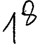
o radiador 23 está disposto de forma a que a direção (direção Fl) do ar levado pela ventoinha de entrada 21 a fluir fique, substancialmente perpendicular à superfície de núcleothe radiator 23 is arranged so that the direction (direction Fl) of the air taken by the inlet fan 21 to flow is substantially perpendicular to the core surface
23a.23a.
Nesta modalidade, uma cobertura de radiador 24 feita de uma resina está disposta em uma lateral da superfície central 23a do-radiador 23 na direção da seta R de modo a cobrir o exterior (uma lateral na direção da seta R) da superfície central 23a. Adicionalmente, a cobertura de radiador 24 constitui um exemplo de uma cobertura de radiador de uma veículo do tipo motoneta da invenção. Tal como mostrado nas Figuras 3 e 4, a cobertura de radiador 24 é conformada com quatro orifícios 24a para inserção de parafusos. Como mostrado na Figura 2, membros de parafusos 25 são aparafusados em orifícios rosqueados 22a do suporte 22 através dos orifícios para inserção de parafusos 24a, pelo que a cobertura de radiador 24 é montada no suporte 22.In this embodiment, a radiator cover 24 made of a resin is arranged on one side of the central surface 23a of the radiator 23 in the direction of arrow R so as to cover the outside (one side in the direction of arrow R) of the central surface 23a. Additionally, the radiator cap 24 is an example of a radiator cap of a scooter-type vehicle of the invention. As shown in Figures 3 and 4, the radiator cover 24 is formed with four holes 24a for inserting screws. As shown in Figure 2, screw members 25 are screwed into threaded holes 22a of the support 22 through the screw insertion holes 24a, whereby the radiator cover 24 is mounted on the support 22.
Além disso, nesta .modalidade, a cobertura de radiador 24 está provida com um orifício de ventilação frontal 24b, um orifício de ventilação posterior 24c e um orifício de ventilação inferior 24d. Adicionalmente, o orifício de ventilação frontal 24b constitui um exemplo do primeiro orifício de ventilação da invenção e o orifício de ventilação posterior 24c constitui um exemplo do segundo orifício de ventilação da invenção. Além disso, o orifício de ventilação inferior 24d constitui um exemplo do terceiro orifício de ventilação da invenção. Além disso, o orifício de ventilação frontal 24b, o orifício de ventilação posteriorIn addition, in this mode, the radiator cover 24 is provided with a front ventilation hole 24b, a rear ventilation hole 24c and a lower ventilation hole 24d. In addition, the front ventilation hole 24b is an example of the first ventilation hole of the invention and the rear ventilation hole 24c is an example of the second ventilation hole of the invention. In addition, the bottom vent hole 24d is an example of the third vent hole of the invention. In addition, the front ventilation hole 24b, the rear ventilation hole

24c e o orifício de ventilação inferior 24d, respectivamente, são conformados de modo a ficarem opostos à superfície central 23a do radiador 23 (ver Figura 4) e abertos para direções diferentes.24c and the bottom ventilation hole 24d, respectively, are shaped so that they are opposite the central surface 23a of the radiator 23 (see Figure 4) and open in different directions.
O orifício de ventilação frontal 24b está aberto para a direção de movimento (a seta na direção FWD) e conformado de modo a tomar pelo menos uma parte do vento causado pelo movimento F3 (ver Figuras 1 e 4). Especificamente, o orifício de ventilação- frontal 24b é provido no lado frontal (um lado na direção da seta FWD) da cobertura de radiador 24, de modo a ficar aberto para uma direção inclinada em um ângulo predeterminado na direção do movimento (a direção da seta FWD) em relação à direção da largura do veículo (a direção da seta L e a direção da seta R) (ver Figura 3). Além disso, tal como mostrado na Figura 4, o orifício de ventilação frontal 24b está disposto em oposição a uma parte da superfície centrai 23a do radiador 23 na direção do movimento (a direção da seta FWD) de modo a funcionar para direcionar o. ar (o vento causado pelo movimento F3) para uma parte da superfície central 23a na direção de movimento (a direção da seta FWD).The front ventilation hole 24b is open for the direction of movement (the arrow in the FWD direction) and shaped to take at least part of the wind caused by the F3 movement (see Figures 1 and 4). Specifically, the front vent hole 24b is provided on the front side (one side in the direction of the FWD arrow) of the radiator cover 24, so that it is open to a direction inclined at a predetermined angle in the direction of movement (the direction of arrow FWD) in relation to the direction of the vehicle width (the direction of arrow L and the direction of arrow R) (see Figure 3). In addition, as shown in Figure 4, the front vent hole 24b is arranged opposite a portion of the central surface 23a of the radiator 23 in the direction of movement (the direction of the arrow FWD) in order to function to direct the. air (the wind caused by movement F3) to a part of the central surface 23a in the direction of movement (the direction of the arrow FWD).
Além disso, nesta modalidade, o orifício de ventilação frontal 24b está provido com uma pluralidade de membros em forma de placa (aletas) 24e, que são conformadas, de forma integral com a cobertura de radiador 24. Cada um dos membros da pluralidade de membros em forma de placa 24e estão respectivamente dispostos de modo a se estender para trás e obliquamente para cima a partir da frente da aberturaIn addition, in this embodiment, the front ventilation hole 24b is provided with a plurality of plate-like members (fins) 24e, which are integrally shaped with the radiator cover 24. Each of the members of the plurality of members plate-shaped 24e are respectively arranged to extend backwards and obliquely upwards from the front of the opening

do orifício de ventilação frontal 24b e não se sobrepor uns aos outros quando vistos em projeção. Além disso, cada um dentre a pluralidade de membros em forma de placa 24e são respectivamente conformados em um ângulo predeterminado de inclinação em relação à superfície central 23a. Além disso, tal como pode ser visto nas Figuras 5 e 6, a pluralidade de cada um dentre a pluralidade de membros em forma de placa 24e (ver Figura 5) está respectivamente disposto de forma a possuir um ângulo de inclinação predeterminado menor do que um ângulo de inclinação predeterminado em que os membros em forma de placa 24f do orifício de ventilação posterior 24c (ver Figura 6) , estão inclinados em relação à superfície central 23a. Isto é, os membros em forma de placa 24e (ver Figura 5) do orifício de ventilação frontal 24b estão dispostos de forma a dificultar a entrada de lama ou similares ao interior (na direção da seta L) da cobertura de radiador 24 em comparação aos membros em forma de placa 24f do orifício de ventilação posterior 24c (ver Figura 6).front vent hole 24b and do not overlap each other when viewed in projection. In addition, each of the plurality of plate-like members 24e are respectively shaped at a predetermined angle of inclination with respect to the central surface 23a. In addition, as can be seen in Figures 5 and 6, the plurality of each of the plurality of plate-shaped members 24e (see Figure 5) is respectively arranged to have a predetermined inclination angle less than one predetermined inclination angle at which the plate-shaped members 24f of the posterior ventilation hole 24c (see Figure 6) are inclined with respect to the central surface 23a. That is, the plate-like members 24e (see Figure 5) of the front ventilation hole 24b are arranged in such a way as to make it difficult for mud or the like to enter the interior (in the direction of arrow L) of the radiator cover 24 compared to plate-shaped members 24f of the posterior ventilation hole 24c (see Figure 6).
Além disso, nesta modalidade, o orifício de ventilação posterior 24c é- conformado tal como mostrado nas Figuras 3 e 4 de modo a ficar aberto em oposição à direção do movimento (a direção da seta FWD) e para tomar um ar de entrada Fl (ver Figura 2) proveniente da ventoinha de entrada / admissão 21 (ver Figura 2). Especificamente, tal como pode ser visto na Figura 3, o orifício de ventilação posterior 24c é provido posteriormente à cobertura de radiador. 24 de modo a ficar aberto para uma direção inclinada em um ângulo predeterminado em uma direção oposta à direção do movimentoIn addition, in this embodiment, the rear ventilation hole 24c is shaped as shown in Figures 3 and 4 so as to be open in opposition to the direction of movement (the direction of the arrow FWD) and to take in an incoming air Fl ( see Figure 2) from the inlet / intake fan 21 (see Figure 2). Specifically, as can be seen in Figure 3, the rear ventilation hole 24c is provided after the radiator cover. 24 so that it is open to a direction inclined at a predetermined angle in a direction opposite to the direction of movement

do veículo (a direção da seta FWD) e a direção da largura do veículo (a direção da seta L e a direção da seta R) (ver Figura 2). Além disso, tal como mostrado na Figura 4, o orifício de ventilação posterior 24c está disposto de forma a es5 tar voltado para um lado oposto da parte superior da superfície central 23a do radiador 23 em relação à direção de movimento (a direção da seta FWD), funcionando para direcionar ar (o vento de entrada Fl) (ver Figura 2) para uma parte oposta da porção superior da superfície central 23a em rela10 ção à direção de movimento (a direção da seta FWD).of the vehicle (the direction of the arrow FWD) and the direction of the width of the vehicle (the direction of the arrow L and the direction of the arrow R) (see Figure 2). In addition, as shown in Figure 4, the rear ventilation hole 24c is arranged to face away from the top of the central surface 23a of the radiator 23 in relation to the direction of movement (the direction of the arrow FWD ), working to direct air (the incoming wind F1) (see Figure 2) to an opposite part of the upper portion of the central surface 23a in relation to the direction of movement (the direction of the arrow FWD).
Além disso, nesta modalidade, o orifício de ventilação posterior 24c está provido com uma pluralidade de membros em forma de placa (aletas) 24f, integrados à cobertura de radiador 24. Cada um dentre a pluralidade de membros em forma de placa 24f está respectivamente disposto de modo a se estender para trás e obliquamente para cima a partir da frente da abertura do orifício de ventilação posterior 24c e não se sobrepor uns aos outros quando observados em projeção. Além dissó, cada um dentre a.pluralidade de membros em forma de placa 2.4f é respectivamente conformado com um ângulo predeterminado de inclinação em relação à superfície central 23a. Além disso, como pode ser visto nas Figuras 5 e 6, cada um dentre a pluralidade de membros em forma de placa 24f (ver Figura 6) está respectivamente disposto de forma a possuir um ângulo predeterminado de inclinação maior do que um ângulo predeterminado de inclinação em que os membros em forma de placa 24e (ver Figura 5) do orifício de ventilação frontal 24b estão inclinados em relação à superfície centralIn addition, in this embodiment, the rear ventilation hole 24c is provided with a plurality of plate-like members (fins) 24f, integrated with the radiator cover 24. Each of the plurality of plate-like members 24f is respectively arranged so as to extend backwards and obliquely upwards from the front of the rear vent hole opening 24c and not overlap each other when viewed in projection. In addition, each of the plurality of plate-shaped members 2.4f is respectively conformed to a predetermined angle of inclination with respect to the central surface 23a. In addition, as can be seen in Figures 5 and 6, each of the plurality of plate-shaped members 24f (see Figure 6) is respectively arranged to have a predetermined angle of inclination greater than a predetermined angle of inclination where the plate-like members 24e (see Figure 5) of the front ventilation hole 24b are angled in relation to the central surface

23a. Isto é, os membros em forma de placa 24f (ver Figura 6) do orifício de ventilação posterior 24c estão dispostos de modo a que o ar seja capaz de entrar para o interior (na direção da seta L) da cobertura de radiador 24, em comparação aos membros em forma de placa 24e do orifício de ventilação frontal 24b (ver Figura 5).23a. That is, the plate-shaped members 24f (see Figure 6) of the rear ventilation hole 24c are arranged so that air is able to enter the interior (in the direction of arrow L) of the radiator cover 24, in comparison to the plate-like members 24 and the front ventilation hole 24b (see Figure 5).
Além disso, nesta modalidade, tal como pode ser visto nas Figuras 1 e 4, o orifício de ventilação inferior 24d é provido de modo a ficar aberto para uma direção em que pelo menos parte do vento decorrente do movimento F4 (ver Figura 1) abaixo do orifício de ventilação frontal 24b possa ser tomado, abaixo do orifício de ventilação posterior 2 4c. Especificamente, uma parte de parede 24g conformada de modo a se projetar na direção da seta R (ver Figura 3) e a cobrir uma parte inferior da superfície central 23a do radiador 23 é provida abaixo do orifício de ventilação posterior 24c,e o orifício de ventilação inferior 24d é formado entre o orifício de ventilação posterior 24c e a parte de parede 24g. Além disso, o orifício de ventilação inferior 24d está conformado de modo a se estender obliquamente para baixo na direção do movimento (a direção da seta FWD) . 0 orifício de ventilação inferior 24d está disposto de modo a ficar voltado para um lado oposto da parte inferior da superfície central 23a do radiador 23 em relação à direção de movimento (a direção da seta FWD) e para direcionar o ar (o vento decorrente do movimento F4) (ver Figura 1) para uma parte oposta da parte inferior da superfície central 23a à direção do movimento (a direção da seta FWD).In addition, in this modality, as seen in Figures 1 and 4, the lower ventilation hole 24d is provided so that it is open in a direction in which at least part of the wind due to the F4 movement (see Figure 1) below of the front ventilation hole 24b can be taken, below the rear ventilation hole 2 4c. Specifically, a wall part 24g shaped to project in the direction of the arrow R (see Figure 3) and to cover a lower part of the central surface 23a of the radiator 23 is provided below the rear ventilation hole 24c, and the bottom vent 24d is formed between the rear vent hole 24c and the wall part 24g. In addition, the lower vent hole 24d is shaped so that it extends obliquely downward in the direction of movement (the direction of the arrow FWD). The bottom ventilation hole 24d is arranged so that it faces away from the bottom of the central surface 23a of the radiator 23 in relation to the direction of movement (the direction of the arrow FWD) and to direct the air (the wind due to the movement F4) (see Figure 1) to an opposite part of the lower part of the central surface 23a to the direction of movement (the direction of the arrow FWD).

Além disso, nesta modalidade, tal como ser visto nas Figuras 7 e 8, uma parte de chicana 24h, conformada para levar o ar que flui a partir do orifício de ventilação inferior 24d para uma. parte inferior da superfície central 23a do radiador 23 (ver Figura 8) é provida sobre a cobertura de radiador 24 na parte de parede 24g sobre um lado da superfície posterior (em uma direção da seta L) (ver Figura 7) da cobertura de radiador 24. Além disso, a parte de chicana 24h constitui um exemplo de membro de chicana da invenção. A parte de chicana 24h é provida de modo a se projetar sobre um lado da superfície posterior (na direção da seta L) (ver Figura 7) da parte de parede 24g e inclui uma parte de chicana posterior 24i, que se estende para baixo a partir das vizinhanças de uma extremidade posterior do orifício de ventilação inferior 24d, e uma parte de chicana inferior 24j, que se estende para a frente (na direção da seta FWD) e obliquamente para baixo. A parte de chicana posterior 24i funciona para direcionar o ar para uma parte oposta da parte inferior do radiador 23 (Figura 8) à direção de movimento (a direção da seta FWD), impedindo concomitantemente que o ar (o vento acarretado pelo movimento F4) (ver Figura 8) fluindo a partir do orifício de ventilação inferior 24d vá para trás. Além disso, a parte de chicana inferior 24 j funciona para levar o ar para a parte oposta da parte inferior do radiador 23 (Figura 8) â direção de movimento (a direção da seta FWD) , impedindo concomitantemente que o ar (o vento acarretado pelo movimento F4) (ver Figura 8) que flui a partir do orifício de ventilação inferior 24d vá para baixo.Furthermore, in this embodiment, as seen in Figures 7 and 8, a part of baffle 24h, shaped to take the air flowing from the lower ventilation hole 24d to one. the bottom part of the central surface 23a of the radiator 23 (see Figure 8) is provided on the radiator cover 24 in the wall part 24g on one side of the rear surface (in a direction of the arrow L) (see Figure 7) of the radiator cover 24. In addition, the 24h baffle part is an example of baffle member of the invention. The baffle part 24h is provided so that it projects on one side of the back surface (in the direction of the arrow L) (see Figure 7) of the wall part 24g and includes a baffle part 24i, which extends downwards to from the vicinity of a rear end of the lower ventilation hole 24d, and a part of the lower baffle 24j, which extends forward (in the direction of the FWD arrow) and obliquely downward. The posterior baffle part 24i works to direct the air to an opposite part of the bottom of the radiator 23 (Figure 8) to the direction of movement (the direction of the FWD arrow), concomitantly preventing air (the wind caused by the F4 movement) (see Figure 8) flowing from the bottom vent hole 24d go back. In addition, the lower baffle part 24 j works to take the air to the opposite part of the lower part of the radiator 23 (Figure 8) to the direction of movement (the direction of the FWD arrow), concomitantly preventing the air (the wind caused by movement F4) (see Figure 8) flowing from the lower ventilation hole 24d go down.

Além disso, pelo menos uma parte da porção de chicana inferior 24j está conformada sobre uma parte limite 24k entre duas superfícies incluídas na parte de parede 24g.In addition, at least a part of the lower baffle portion 24j is formed on a boundary part 24k between two surfaces included in the wall part 24g.
Além disso, nesta modalidade, tal como pode ser visto nas Figuras 3 e 4, uma parte de viga 241 para divisão do orifício de ventilação frontal 24b e do orifício de ventilação posterior 24c é provida entre o orifício de ventilação frontal 24b e o orifício de ventilação posterior 24c. Como pode ser visto nas Figuras 3 e 9, a parte de viga 241 é conformada para se estender verticalmente entre o orifício de ventilação frontal 24b e o orifício de ventilação posterior 24c e para se projetar por a parte mais externo sobre um lado oposto (um lado na direção da seta R) do radiador 23 até a superfície centrai 23a. Além disso, uma parte de cobertura de tampa 24m conformada de modo a cobrir uma tampa de radiador 23c (ver Figura 6) é provida sobre uma parte posterior, superior, da cobertura de radiador 24.In addition, in this embodiment, as can be seen in Figures 3 and 4, a beam part 241 for dividing the front ventilation hole 24b and the rear ventilation hole 24c is provided between the front ventilation hole 24b and the ventilation hole. posterior ventilation 24c. As can be seen in Figures 3 and 9, the beam part 241 is shaped to extend vertically between the front ventilation hole 24b and the rear ventilation hole 24c and to project from the outermost part on an opposite side (a side in the direction of the arrow R) of the radiator 23 to the center surface 23a. In addition, a cap cover part 24m shaped to cover a radiator cap 23c (see Figure 6) is provided on a rear, upper part of the radiator cap 24.
Além disso, uma roda traseira 26 é provida de forma rotativa posteriormente ao motor 11. Além disso, um páralama posterior 27 está montado acima da roda traseira 26 para cobrir uma parte superior da roda traseira 26. Além disso, um cano de escapamento 28 está conectado ao motor 11. O cano de escapamento 28 está direcionado para trás e conectado a um silencioso 29.In addition, a rear wheel 26 is rotatably provided after the engine 11. In addition, a rear fender 27 is mounted above the rear wheel 26 to cover an upper part of the rear wheel 26. In addition, an exhaust pipe 28 is connected to the engine 11. The exhaust pipe 28 is directed backwards and connected to a muffler 29.
Na modalidade, tal como acima descrito, pelo provimento de uma pluralidade de orifícios de ventilação (o orifício de ventilação frontal 24b, o orifício de ventilação posterior 24c e o orifício de ventilação inferior 24d) aber20In the embodiment, as described above, by providing a plurality of ventilation holes (the front ventilation hole 24b, the rear ventilation hole 24c and the lower ventilation hole 24d) open20

tos para diferentes direções sobre o radiador 23, do qual a superfície central 23a está disposta na direção da seta R (lateralmente ao veículo) de forma a cobrir uma parte externa (na direção da seta R) da superfície central 23a, a pluralidade de orifícios de ventilação (o orifício de ventilação frontal 24b, o orifício de ventilação posterior 24c e o orifício de ventilação inferior 24d) abertos para diferentes direções, pode tomar ar para refrigeração do radiador 23 em uma pluralidade de direções. Consequentemente, é possível melhorar a eficiência de tomada de ar para refrigeração do radiador 23,different directions on the radiator 23, of which the central surface 23a is arranged in the direction of the arrow R (laterally to the vehicle) in order to cover an external part (in the direction of the arrow R) of the central surface 23a, the plurality of holes ventilation holes (the front ventilation hole 24b, the rear ventilation hole 24c and the lower ventilation hole 24d) opened in different directions, can take air for cooling the radiator 23 in a plurality of directions. Consequently, it is possible to improve the air intake efficiency for cooling the radiator 23,
Além disso, nesta modalidade, pelo provimento em um orifício de ventilação do orifício de ventilação frontal 24b, que está aberto para a direção do movimento (a direção da seta FWD) e capta pelo menos uma parte do vento causado pelo movimento F3, e o orifício de ventilação posterior 24c, que está aberto para uma direção oposta à direção do movimento (a direção da seta FWD) e capta o vento causado pelo movimento F1 da ventoinha de entrada 21 disposta sobre uma superfície oposta (na direção da seta L) do radiador 23 para a superfície central 23a, é possível prontamente levar o vento causado pelo movimento F3 a penetrar a partir do orifício de ventilação frontal 24b para tomada de ar para refrigeração do radiador 23 e levar o vento de entrada F1 proveniente da ventoinha de entrada 21 para penetrar a partir do orifício de ventilação posterior 24c para tomada de ar para refrigeração do radiador 23.In addition, in this mode, by providing a ventilation hole for the front ventilation hole 24b, which is open for the direction of movement (the direction of the FWD arrow) and captures at least part of the wind caused by the F3 movement, and the posterior ventilation hole 24c, which is open in a direction opposite to the direction of movement (the direction of the FWD arrow) and captures the wind caused by the F1 movement of the inlet fan 21 arranged on an opposite surface (in the direction of the L arrow). radiator 23 to the central surface 23a, it is possible to readily take the wind caused by the movement F3 to penetrate from the front ventilation hole 24b for air intake for cooling the radiator 23 and to take the incoming wind F1 from the input fan 21 to penetrate from the rear ventilation hole 24c for air intake for cooling the radiator 23.
Além disso, nesta modalidade, ao fazer os ângulosFurthermore, in this modality, when making the angles

de inclinação da pluralidade de membros em forma de placas 24e em relação à superfície central 23a menores do que os ângulos de inclinação dos membros em forma de placa 24f em relação à superfície central 23a, pode se impedir que respingos de lama ou similares penetrem no orifício de ventilação frontal 24b, no qual respingos de lama ou similares podem penetrar na direção do movimento (a direção da seta FWD) em comparação com o orifício de ventilação posterior 24c aberto para uma direção oposta à direção do movimento (a direção da seta FWD) , na direção do movimento (a direção da seta FWD).of inclination of the plurality of plate-shaped members 24e with respect to the central surface 23a less than the angles of inclination of the plate-like members 24f with respect to the central surface 23a, splashes of mud or the like may be prevented from penetrating the orifice front ventilation fan 24b, in which mud spatter or the like can penetrate in the direction of movement (the direction of the FWD arrow) compared to the rear ventilation hole 24c opened in a direction opposite to the direction of movement (the direction of the FWD arrow) , in the direction of movement (the direction of the FWD arrow).
Além disso, nesta modalidade, através da disposição da pluralidade de membros em forma de placa 24e respectivamente de modo a não se sobrepor uns aos outros quando observados em projeção, é possível impedir a penetração do vento causado pelo movimento F3 seja . obstruída impedindo concomitantemente a entrada de lama e similares provenientes do orifício de ventilação, frontal 24b.In addition, in this embodiment, by arranging the plurality of plate-like members 24e respectively so as not to overlap each other when viewed in projection, it is possible to prevent the penetration of the wind caused by the F3 movement. obstructed concomitantly preventing the entry of mud and the like from the ventilation hole, front 24b.
Além disso, nesta modalidade, pelo provimerito sobre a parte de parede 24g do orifício de ventilação inferior 24d, o qual é provido de modo a estar aberto em uma direção em que pelo menos uma parte do vento causado pelo movimento F4 pode ser tomado, o orifício de ventilação inferior 24d, além do orifício de ventilação frontal 24b, permite que o vento do movimento F4 penetre, de forma a ser possível melhorar adicionalmente a eficiência de tomada.In addition, in this modality, through the provision on the wall part 24g of the lower ventilation hole 24d, which is provided so that it is open in a direction in which at least a part of the wind caused by the F4 movement can be taken, the lower ventilation hole 24d, in addition to the front ventilation hole 24b, allows the wind of the F4 movement to penetrate, so that it is possible to further improve the efficiency of the socket.
Além disso, nesta modalidade, pela disposição do orifício de ventilação frontal 24b em oposição a uma parte da superfície central 23a na direção do movimento (a direção da seta FWD), pela disposição do orifício de ventilação posterior 24c em oposição a uma parte superior da superfície central 23a à direção do movimento (a direção da seta FWD) e pela disposição do orifício de ventilação inferior 24d em oposição a uma parte oposta da parte inferior da superfície central 23a à direção de movimento (a direção da seta FWD) , o orifício de ventilação frontal 24b permite a tomada do ar para refrigeração de uma lateral da superfície central 23a na direção do movimento (a direção da seta FWD), o orifício de ventilação posterior 24c permite a tomada de ar para refrigeração de uma parte oposta da parte superior da superfície central 23e à direção de movimento (a direção da seta FWD), e o orifício de ventilação inferior 24d permite a tomada de ar para refrigeração de uma parte oposta da parte inferior da superfície central 23a à direção do movimento (a direção da seta FWD).In addition, in this embodiment, by the arrangement of the front ventilation hole 24b in opposition to a part of the central surface 23a in the direction of movement (the direction of the arrow FWD), by the arrangement of the posterior ventilation hole 24c in opposition to an upper part of the central surface 23a to the direction of movement (the direction of the arrow FWD) and the arrangement of the lower ventilation hole 24d as opposed to an opposite part of the bottom of the central surface 23a to the direction of movement (the direction of the arrow FWD), the hole front ventilation fan 24b allows the intake of cooling air from one side of the central surface 23a in the direction of movement (the direction of the arrow FWD), the rear ventilation hole 24c allows intake of cooling air from an opposite part of the upper part from the central surface 23e to the direction of movement (the direction of the arrow FWD), and the bottom ventilation hole 24d allows air intake to cool an opposite part of the lower part of the central surface 23a to the direction of movement (the direction of the arrow FWD).
Além disso, nesta modalidade, pelo provimento da parte de chicana 24h, gue é provida sobre um lado (a direção da seta L) da parte de parede 24g em direção ao radiador 23 para levar o ar, que flui a partir do orifício de ventilação inferior 24d, para a parte inferior da superfície central 23a do radiador 23, a parte de chicana 24h pode impedir o vento do movimento F4, que flui a partir do orifício de ventilação inferior 24d, de ir para trás de forma a que o vento do movimento F4 que flui a partir do orifício de ventilação inferior 24d possa ser levado eficientemente para a parte inferior da superfície central 23a do radiador 23.In addition, in this modality, by providing the chicane part 24h, which is provided on one side (the direction of the arrow L) of the wall part 24g towards the radiator 23 to carry the air, which flows from the ventilation hole bottom 24d, to the bottom of the central surface 23a of the radiator 23, the baffle part 24h can prevent the wind from movement F4, which flows from the bottom ventilation hole 24d, from going backwards so that the wind from the movement F4 flowing from the lower ventilation hole 24d can be efficiently carried to the bottom of the central surface 23a of the radiator 23.

Além disso, nesta modalidade, pela formação da parte de viga 241 de forma a se projetar pelo exterior sobre um lado oposto (um lado na direção da seta R) do radiador 23 à superfície central 23a, é possível aumentar um espaço entre a superfície central 23a do radiador 23 e a superfície posterior da cobertura de radiador 24, de forma a que o ar tomado possa ser transportado para o espaço entre a superfície central 23a do radiador 23 e a superfície posterior da cobertura de radiador 24. Desse modo, o ar tomado pode ser distribuído por toda a superfície central 23a do radiador 23, de modo a melhorar a eficiência de refrigeração do radiador 23.In addition, in this embodiment, by forming the beam part 241 in order to project from the outside on an opposite side (one side in the direction of the arrow R) of the radiator 23 to the central surface 23a, it is possible to increase a space between the central surface 23a of the radiator 23 and the rear surface of the radiator cover 24, so that the air taken can be transported to the space between the central surface 23a of the radiator 23 and the rear surface of the radiator cover 24. Thus, the air taken can be distributed over the central surface 23a of the radiator 23, in order to improve the cooling efficiency of the radiator 23.
Além disso, deve ser considerado que a modalidade aqui descrita, em todos os respeitos, é exemplar e não limitativa. O escopo da invenção não é indicado pelas descrições da modalidade acima descrita, mas sim pelas reivindicações, devendo ser incluídas no mesmo todas as mudanças que se insiram no significado e amplitude de equivalência das reivindicações.In addition, it must be considered that the modality described here, in all respects, is exemplary and not limiting. The scope of the invention is not indicated by the descriptions of the modality described above, but by the claims, and all changes that fall within the meaning and breadth of equivalence of the claims must be included in it.
Apesar de a modalidade apresentar uma motocicleta do tipo motoneta ou scooter, como exemplo de um veículo do tipo motoneta provido com uma cobertura de radiador, a invenção não fica limitada à mesma, podendo ser aplicada a outros veículos tais como triciclos, um ATV (veículo para qualquer terreno), etc., contanto que eles sejam do tipo motoneta com uma cobertura de radiador.Although the modality features a scooter or scooter type motorcycle, as an example of a scooter type vehicle provided with a radiator cover, the invention is not limited to it, it can be applied to other vehicles such as tricycles, an ATV (vehicle for any terrain), etc., as long as they are of the scooter type with a radiator cover.
Além disso, apesar de a modalidade apresentar um exemplo em que um orifício de ventilação frontal está abertoIn addition, although the modality presents an example where a front ventilation hole is open

na direção do movimento para captar pelo menos uma parte do vento do movimento, a invenção não fica limitada à mesma, um orifício de ventilação podendo ser formado para tomar pelo menos uma parte do vento causado pelo movimento através, por exemplo, de um duto, contanto que o orifício de ventilação possa captar pelo menos uma parte do vento do movimento.in the direction of movement to capture at least a part of the wind from the movement, the invention is not limited to it, a ventilation hole can be formed to take at least a part of the wind caused by the movement through, for example, a duct, as long as the ventilation hole can capture at least part of the movement wind.
Além disso, apesar de a modalidade apresentar um exemplo em que a superfície central do radiador está disposta lateralmente ao corpo do veículo, a invenção não fica limitada ao mesmo, a superfície central de um radiador podendo ser disposta em uma direção inclinada em um ângulo predeterminado à direção da largura do veículo, em uma direção do movimento ou em uma direção oposta à direção do movimento.In addition, although the modality presents an example in which the central surface of the radiator is arranged laterally to the vehicle body, the invention is not limited to it, the central surface of a radiator can be arranged in an inclined direction at a predetermined angle to the direction of vehicle width, in a direction of movement or in a direction opposite to the direction of movement.
Além disso, apesar de a modalidade apresentar um exemplo em que são providos orifícios de ventilação em três locais, a invenção não fica limitada a tal, podendo ser providos orifícios de ventilação em quatro ou mas locais, ou providos em apenas dois locais.Furthermore, although the modality presents an example in which ventilation holes are provided in three places, the invention is not limited to this, and ventilation holes can be provided in four or more places, or provided in only two places.
Além disso, apesar de a modalidade apresentar um exemplo em que o vento de entrada da ventoinha de entrada é tomado através do orifício de ventilação posterior, a invenção não fica limitada ao mesmo, um ar que não o vento de entrada de uma ventoinha de entrada, tal como o vento causado pelo movimento, etc., pode ser levado a fluir para o interior do orifício de ventilação posterior.In addition, although the modality presents an example in which the inlet wind of the inlet fan is taken through the rear ventilation hole, the invention is not limited to it, an air other than the inlet wind of an inlet fan , such as wind caused by movement, etc., can be caused to flow into the rear ventilation hole.
Além disso, apesar de a modalidade apresentar um exemplo em que os membros em forma de placa estão dispostos sobre o orifício de ventilação frontal e o orifício de ven25 tilação posterior, a invenção não fica limitado ao mesmo, os membros em forma de placa podendo também ser dispostos sobre o orifício de ventilação inferior.In addition, although the modality presents an example in which the plate-shaped members are arranged over the front ventilation hole and the posterior ventilation hole, the invention is not limited to it, the plate-shaped members can also be arranged over the bottom ventilation hole.
Além disso, apesar de a modalidade apresentar um exemplo em que a parte de chicana formada para levar o ar que flui a partir do orifício de ventilação inferior para a parte inferior da superfície central do radiador ser provida sobre o lado da superfície posterior da cobertura do radiador e a parte de chicana compreender a parte de chicana posterior, que se estende para baixo a partir das vizinhanças de uma extremidade posterior do orifício de ventilação inferior, e a parte de chicana inferior, que está conectada à extremidade inferior da parte de chicana posterior e se estende para a frente e obliquamente para baixo, a invenção não fica limitada ao mesmo, uma parte de chicana podendo ser provida sobre o lado da superfície posterior da cobertura de radiador exceto a parte de chicana posterior e a parte de chicana inferior, por exemplo, para trás do orifício de ventilação posterior sobre o lado da superfície posterior da cobertura de radiador.'Furthermore, although the modality presents an example in which the baffle part formed to carry the air flowing from the lower ventilation hole to the bottom of the central surface of the radiator is provided on the side of the back surface of the the radiator and the baffle portion comprise the posterior baffle portion, which extends downwardly from the vicinity of a rear end of the lower vent hole, and the lower baffle portion, which is connected to the lower end of the posterior baffle portion and extends forward and obliquely downward, the invention is not limited to it, a part of baffle may be provided on the side of the back surface of the radiator cover except the part of the posterior baffle and the part of the lower baffle, for example, behind the rear ventilation hole on the side of the rear surface of the radiator cap. '
Além disso, apesar de a modalidade apresentar um exemplo em que a parte de cobertura de tampa ser provida de maneira a cobrir a tampa de radiador do radiador, a invenção não fica limitada a tal, podendo ser dispensado o provimento da parte de cobertura de tampa, que cobre a tampa de radiador do radiador.In addition, although the embodiment presents an example in which the cap cover part is provided in such a way as to cover the radiator cap of the radiator, the invention is not limited to this, and the cap cover part can be dispensed with. , which covers the radiator cap of the radiator.
Claims (15)
Applications Claiming Priority (2)
| Application Number | Priority Date | Filing Date | Title |
|---|---|---|---|
| JP2007-131630 | 2007-05-17 | ||
| JP2007131630A JP2008284992A (en) | 2007-05-17 | 2007-05-17 | Radiator cover for saddle riding type vehicle and saddle riding type vehicle equipped with the same |
Publications (2)
| Publication Number | Publication Date |
|---|---|
| BRPI0801488A2 BRPI0801488A2 (en) | 2009-01-06 |
| BRPI0801488B1 true BRPI0801488B1 (en) | 2018-05-02 |
Family
ID=39717679
Family Applications (1)
| Application Number | Title | Priority Date | Filing Date |
|---|---|---|---|
| BRPI0801488-4A BRPI0801488B1 (en) | 2007-05-17 | 2008-05-15 | COVER FOR MOTONE TYPE VEHICLE RADIATOR AND MOTONE TYPE VEHICLE PROVIDED WITH THE SAME |
Country Status (6)
| Country | Link |
|---|---|
| EP (1) | EP1992514B1 (en) |
| JP (1) | JP2008284992A (en) |
| CN (1) | CN101306704B (en) |
| AT (1) | ATE513704T1 (en) |
| BR (1) | BRPI0801488B1 (en) |
| ES (1) | ES2366761T3 (en) |
Families Citing this family (8)
| Publication number | Priority date | Publication date | Assignee | Title |
|---|---|---|---|---|
| JP2010076751A (en) * | 2008-08-29 | 2010-04-08 | Yamaha Motor Co Ltd | Motorcycle |
| JP2012017085A (en) * | 2010-06-11 | 2012-01-26 | Yamaha Motor Co Ltd | Saddle-ride type vehicle |
| CN102556132B (en) * | 2012-01-20 | 2014-12-17 | 美固龙金属制品(中国)有限公司 | Children's seat board of shopping cart and children's seat of shopping cart |
| EP2716532B1 (en) * | 2012-10-08 | 2015-04-08 | Yamaha Motor Co., Ltd. | Straddle-type vehicle |
| JP6038844B2 (en) * | 2014-06-26 | 2016-12-07 | 本田技研工業株式会社 | Cooling device for internal combustion engine for saddle riding type vehicle |
| CN210310698U (en) * | 2019-05-31 | 2020-04-14 | 赛格威科技有限公司 | All-terrain vehicle |
| JP6997141B2 (en) * | 2019-07-19 | 2022-01-17 | 本田技研工業株式会社 | Saddle-type vehicle |
| CN116409420B (en) * | 2021-12-30 | 2026-01-27 | 浙江春风动力股份有限公司 | Electric motor cycle |
Family Cites Families (5)
| Publication number | Priority date | Publication date | Assignee | Title |
|---|---|---|---|---|
| JPH01233186A (en) * | 1989-01-27 | 1989-09-18 | Yamaha Motor Co Ltd | Engine cooling device for scooter type motorcycle |
| JP2576872Y2 (en) | 1990-10-05 | 1998-07-16 | 本田技研工業株式会社 | Engine cooling system for scooter type small vehicle |
| JPH09249170A (en) * | 1996-03-15 | 1997-09-22 | Yamaha Motor Co Ltd | Scooter type vehicle |
| JP3791897B2 (en) * | 2000-12-05 | 2006-06-28 | 本田技研工業株式会社 | Wind guide structure at the front of the vehicle body in a scooter type vehicle |
| JP3696508B2 (en) * | 2000-12-28 | 2005-09-21 | 本田技研工業株式会社 | Radiator device for vehicle |
-
2007
- 2007-05-17 JP JP2007131630A patent/JP2008284992A/en active Pending
-
2008
- 2008-05-14 AT AT08251703T patent/ATE513704T1/en not_active IP Right Cessation
- 2008-05-14 EP EP08251703A patent/EP1992514B1/en active Active
- 2008-05-14 ES ES08251703T patent/ES2366761T3/en active Active
- 2008-05-15 BR BRPI0801488-4A patent/BRPI0801488B1/en not_active IP Right Cessation
- 2008-05-19 CN CN2008100932674A patent/CN101306704B/en active Active
Also Published As
| Publication number | Publication date |
|---|---|
| EP1992514B1 (en) | 2011-06-22 |
| ES2366761T3 (en) | 2011-10-25 |
| CN101306704A (en) | 2008-11-19 |
| CN101306704B (en) | 2013-06-12 |
| JP2008284992A (en) | 2008-11-27 |
| BRPI0801488A2 (en) | 2009-01-06 |
| ATE513704T1 (en) | 2011-07-15 |
| EP1992514A1 (en) | 2008-11-19 |
Similar Documents
| Publication | Publication Date | Title |
|---|---|---|
| BRPI0801488B1 (en) | COVER FOR MOTONE TYPE VEHICLE RADIATOR AND MOTONE TYPE VEHICLE PROVIDED WITH THE SAME | |
| US7793748B2 (en) | Vehicle cowl with opening for horn | |
| CN101424210B (en) | Radiator cover and straddle-type vehicle having the same | |
| JP3159207U (en) | Motorcycle | |
| TWI653174B (en) | Straddle type vehicle | |
| BRPI1001707A2 (en) | Motorcycle | |
| JP6130119B2 (en) | Motorcycle | |
| EP2055624B1 (en) | Vehicle with unit swing engine and radiator | |
| EP2055520B1 (en) | Radiator cover and straddle-type vehicle having the same | |
| JP3140231B2 (en) | Shroud opening structure for cooling air intake of air-cooled internal combustion engine for vehicles | |
| BR102016003183B1 (en) | VEHICLE FRONT STRUCTURE OF THE TYPE TO ASSEMBLE | |
| JP2011011570A (en) | Front cowling for motorcycle | |
| JP5932920B2 (en) | Front structure of motorcycle body cover | |
| JP6270321B2 (en) | Two-wheeled vehicle radiator structure | |
| EP2159093A1 (en) | Motorcycle | |
| JPS6247756B2 (en) | ||
| JP3716063B2 (en) | Storage box for motorcycle | |
| JP6083816B2 (en) | Front structure of motorcycle body cover | |
| BRPI0608984A2 (en) | motorcycle | |
| JPS6225988Y2 (en) | ||
| JP6254572B2 (en) | Cooling device for unit swing type internal combustion engine | |
| JP6175123B2 (en) | Radiator structure for saddle-ride type vehicles | |
| JPS635315B2 (en) | ||
| TWI516387B (en) | Straddle type vehicle | |
| JPH08142956A (en) | Motorcycle mudguard structure |
Legal Events
| Date | Code | Title | Description |
|---|---|---|---|
| B03A | Publication of a patent application or of a certificate of addition of invention [chapter 3.1 patent gazette] | ||
| B09A | Decision: intention to grant [chapter 9.1 patent gazette] | ||
| B16A | Patent or certificate of addition of invention granted [chapter 16.1 patent gazette] | ||
| B21F | Lapse acc. art. 78, item iv - on non-payment of the annual fees in time |
Free format text: REFERENTE A 18A ANUIDADE. |