BRPI0802196B1 - axis manufacturing method - Google Patents
axis manufacturing method Download PDFInfo
- Publication number
- BRPI0802196B1 BRPI0802196B1 BRPI0802196-1A BRPI0802196A BRPI0802196B1 BR PI0802196 B1 BRPI0802196 B1 BR PI0802196B1 BR PI0802196 A BRPI0802196 A BR PI0802196A BR PI0802196 B1 BRPI0802196 B1 BR PI0802196B1
- Authority
- BR
- Brazil
- Prior art keywords
- magnet
- mold
- shaft
- seat
- axis
- Prior art date
Links
- 238000004519 manufacturing process Methods 0.000 title claims abstract description 19
- 229920000642 polymer Polymers 0.000 claims abstract description 13
- 238000000034 method Methods 0.000 claims abstract description 12
- 229920003023 plastic Polymers 0.000 claims abstract description 12
- 238000002485 combustion reaction Methods 0.000 claims abstract description 10
- 239000000463 material Substances 0.000 claims abstract description 9
- 238000001746 injection moulding Methods 0.000 claims abstract 4
- 230000015572 biosynthetic process Effects 0.000 claims abstract 3
- 238000002347 injection Methods 0.000 claims description 15
- 239000007924 injection Substances 0.000 claims description 15
- 238000005266 casting Methods 0.000 claims 1
- 239000011159 matrix material Substances 0.000 description 3
- 239000011230 binding agent Substances 0.000 description 2
- 239000007769 metal material Substances 0.000 description 2
- 239000002245 particle Substances 0.000 description 2
- 239000000843 powder Substances 0.000 description 2
- 229910052779 Neodymium Inorganic materials 0.000 description 1
- 230000004308 accommodation Effects 0.000 description 1
- 238000013037 co-molding Methods 0.000 description 1
- 238000010586 diagram Methods 0.000 description 1
- 230000000694 effects Effects 0.000 description 1
- 239000003292 glue Substances 0.000 description 1
- 238000009413 insulation Methods 0.000 description 1
- 230000005415 magnetization Effects 0.000 description 1
- 229910052751 metal Inorganic materials 0.000 description 1
- 239000002184 metal Substances 0.000 description 1
- QEFYFXOXNSNQGX-UHFFFAOYSA-N neodymium atom Chemical compound [Nd] QEFYFXOXNSNQGX-UHFFFAOYSA-N 0.000 description 1
- 239000007787 solid Substances 0.000 description 1
Images


Classifications
-
- G—PHYSICS
- G01—MEASURING; TESTING
- G01D—MEASURING NOT SPECIALLY ADAPTED FOR A SPECIFIC VARIABLE; ARRANGEMENTS FOR MEASURING TWO OR MORE VARIABLES NOT COVERED IN A SINGLE OTHER SUBCLASS; TARIFF METERING APPARATUS; MEASURING OR TESTING NOT OTHERWISE PROVIDED FOR
- G01D5/00—Mechanical means for transferring the output of a sensing member; Means for converting the output of a sensing member to another variable where the form or nature of the sensing member does not constrain the means for converting; Transducers not specially adapted for a specific variable
- G01D5/12—Mechanical means for transferring the output of a sensing member; Means for converting the output of a sensing member to another variable where the form or nature of the sensing member does not constrain the means for converting; Transducers not specially adapted for a specific variable using electric or magnetic means
- G01D5/14—Mechanical means for transferring the output of a sensing member; Means for converting the output of a sensing member to another variable where the form or nature of the sensing member does not constrain the means for converting; Transducers not specially adapted for a specific variable using electric or magnetic means influencing the magnitude of a current or voltage
- G01D5/142—Mechanical means for transferring the output of a sensing member; Means for converting the output of a sensing member to another variable where the form or nature of the sensing member does not constrain the means for converting; Transducers not specially adapted for a specific variable using electric or magnetic means influencing the magnitude of a current or voltage using Hall-effect devices
- G01D5/145—Mechanical means for transferring the output of a sensing member; Means for converting the output of a sensing member to another variable where the form or nature of the sensing member does not constrain the means for converting; Transducers not specially adapted for a specific variable using electric or magnetic means influencing the magnitude of a current or voltage using Hall-effect devices influenced by the relative movement between the Hall device and magnetic fields
-
- B—PERFORMING OPERATIONS; TRANSPORTING
- B29—WORKING OF PLASTICS; WORKING OF SUBSTANCES IN A PLASTIC STATE IN GENERAL
- B29C—SHAPING OR JOINING OF PLASTICS; SHAPING OF MATERIAL IN A PLASTIC STATE, NOT OTHERWISE PROVIDED FOR; AFTER-TREATMENT OF THE SHAPED PRODUCTS, e.g. REPAIRING
- B29C45/00—Injection moulding, i.e. forcing the required volume of moulding material through a nozzle into a closed mould; Apparatus therefor
- B29C45/0013—Injection moulding, i.e. forcing the required volume of moulding material through a nozzle into a closed mould; Apparatus therefor using fillers dispersed in the moulding material, e.g. metal particles
-
- B—PERFORMING OPERATIONS; TRANSPORTING
- B29—WORKING OF PLASTICS; WORKING OF SUBSTANCES IN A PLASTIC STATE IN GENERAL
- B29C—SHAPING OR JOINING OF PLASTICS; SHAPING OF MATERIAL IN A PLASTIC STATE, NOT OTHERWISE PROVIDED FOR; AFTER-TREATMENT OF THE SHAPED PRODUCTS, e.g. REPAIRING
- B29C45/00—Injection moulding, i.e. forcing the required volume of moulding material through a nozzle into a closed mould; Apparatus therefor
- B29C45/16—Making multilayered or multicoloured articles
-
- F—MECHANICAL ENGINEERING; LIGHTING; HEATING; WEAPONS; BLASTING
- F02—COMBUSTION ENGINES; HOT-GAS OR COMBUSTION-PRODUCT ENGINE PLANTS
- F02D—CONTROLLING COMBUSTION ENGINES
- F02D9/00—Controlling engines by throttling air or fuel-and-air induction conduits or exhaust conduits
- F02D9/08—Throttle valves specially adapted therefor; Arrangements of such valves in conduits
- F02D9/10—Throttle valves specially adapted therefor; Arrangements of such valves in conduits having pivotally-mounted flaps
- F02D9/1035—Details of the valve housing
- F02D9/105—Details of the valve housing having a throttle position sensor
-
- F—MECHANICAL ENGINEERING; LIGHTING; HEATING; WEAPONS; BLASTING
- F02—COMBUSTION ENGINES; HOT-GAS OR COMBUSTION-PRODUCT ENGINE PLANTS
- F02D—CONTROLLING COMBUSTION ENGINES
- F02D9/00—Controlling engines by throttling air or fuel-and-air induction conduits or exhaust conduits
- F02D9/08—Throttle valves specially adapted therefor; Arrangements of such valves in conduits
- F02D9/10—Throttle valves specially adapted therefor; Arrangements of such valves in conduits having pivotally-mounted flaps
- F02D9/107—Manufacturing or mounting details
-
- F—MECHANICAL ENGINEERING; LIGHTING; HEATING; WEAPONS; BLASTING
- F02—COMBUSTION ENGINES; HOT-GAS OR COMBUSTION-PRODUCT ENGINE PLANTS
- F02D—CONTROLLING COMBUSTION ENGINES
- F02D9/00—Controlling engines by throttling air or fuel-and-air induction conduits or exhaust conduits
- F02D9/08—Throttle valves specially adapted therefor; Arrangements of such valves in conduits
- F02D9/10—Throttle valves specially adapted therefor; Arrangements of such valves in conduits having pivotally-mounted flaps
- F02D9/1075—Materials, e.g. composites
- F02D9/108—Plastics
-
- F—MECHANICAL ENGINEERING; LIGHTING; HEATING; WEAPONS; BLASTING
- F16—ENGINEERING ELEMENTS AND UNITS; GENERAL MEASURES FOR PRODUCING AND MAINTAINING EFFECTIVE FUNCTIONING OF MACHINES OR INSTALLATIONS; THERMAL INSULATION IN GENERAL
- F16K—VALVES; TAPS; COCKS; ACTUATING-FLOATS; DEVICES FOR VENTING OR AERATING
- F16K1/00—Lift valves or globe valves, i.e. cut-off apparatus with closure members having at least a component of their opening and closing motion perpendicular to the closing faces
- F16K1/16—Lift valves or globe valves, i.e. cut-off apparatus with closure members having at least a component of their opening and closing motion perpendicular to the closing faces with pivoted closure-members
- F16K1/18—Lift valves or globe valves, i.e. cut-off apparatus with closure members having at least a component of their opening and closing motion perpendicular to the closing faces with pivoted closure-members with pivoted discs or flaps
- F16K1/22—Lift valves or globe valves, i.e. cut-off apparatus with closure members having at least a component of their opening and closing motion perpendicular to the closing faces with pivoted closure-members with pivoted discs or flaps with axis of rotation crossing the valve member, e.g. butterfly valves
-
- F—MECHANICAL ENGINEERING; LIGHTING; HEATING; WEAPONS; BLASTING
- F16—ENGINEERING ELEMENTS AND UNITS; GENERAL MEASURES FOR PRODUCING AND MAINTAINING EFFECTIVE FUNCTIONING OF MACHINES OR INSTALLATIONS; THERMAL INSULATION IN GENERAL
- F16K—VALVES; TAPS; COCKS; ACTUATING-FLOATS; DEVICES FOR VENTING OR AERATING
- F16K37/00—Special means in or on valves or other cut-off apparatus for indicating or recording operation thereof, or for enabling an alarm to be given
- F16K37/0025—Electrical or magnetic means
- F16K37/0033—Electrical or magnetic means using a permanent magnet, e.g. in combination with a reed relays
-
- F—MECHANICAL ENGINEERING; LIGHTING; HEATING; WEAPONS; BLASTING
- F16—ENGINEERING ELEMENTS AND UNITS; GENERAL MEASURES FOR PRODUCING AND MAINTAINING EFFECTIVE FUNCTIONING OF MACHINES OR INSTALLATIONS; THERMAL INSULATION IN GENERAL
- F16K—VALVES; TAPS; COCKS; ACTUATING-FLOATS; DEVICES FOR VENTING OR AERATING
- F16K37/00—Special means in or on valves or other cut-off apparatus for indicating or recording operation thereof, or for enabling an alarm to be given
- F16K37/0025—Electrical or magnetic means
- F16K37/0041—Electrical or magnetic means for measuring valve parameters
-
- B—PERFORMING OPERATIONS; TRANSPORTING
- B29—WORKING OF PLASTICS; WORKING OF SUBSTANCES IN A PLASTIC STATE IN GENERAL
- B29K—INDEXING SCHEME ASSOCIATED WITH SUBCLASSES B29B, B29C OR B29D, RELATING TO MOULDING MATERIALS OR TO MATERIALS FOR MOULDS, REINFORCEMENTS, FILLERS OR PREFORMED PARTS, e.g. INSERTS
- B29K2995/00—Properties of moulding materials, reinforcements, fillers, preformed parts or moulds
- B29K2995/0003—Properties of moulding materials, reinforcements, fillers, preformed parts or moulds having particular electrical or magnetic properties, e.g. piezoelectric
- B29K2995/0008—Magnetic or paramagnetic
-
- B—PERFORMING OPERATIONS; TRANSPORTING
- B29—WORKING OF PLASTICS; WORKING OF SUBSTANCES IN A PLASTIC STATE IN GENERAL
- B29L—INDEXING SCHEME ASSOCIATED WITH SUBCLASS B29C, RELATING TO PARTICULAR ARTICLES
- B29L2015/00—Gear wheels or similar articles with grooves or projections, e.g. control knobs
- B29L2015/003—Gears
-
- H—ELECTRICITY
- H01—ELECTRIC ELEMENTS
- H01F—MAGNETS; INDUCTANCES; TRANSFORMERS; SELECTION OF MATERIALS FOR THEIR MAGNETIC PROPERTIES
- H01F1/00—Magnets or magnetic bodies characterised by the magnetic materials therefor; Selection of materials for their magnetic properties
- H01F1/01—Magnets or magnetic bodies characterised by the magnetic materials therefor; Selection of materials for their magnetic properties of inorganic materials
- H01F1/03—Magnets or magnetic bodies characterised by the magnetic materials therefor; Selection of materials for their magnetic properties of inorganic materials characterised by their coercivity
- H01F1/12—Magnets or magnetic bodies characterised by the magnetic materials therefor; Selection of materials for their magnetic properties of inorganic materials characterised by their coercivity of soft-magnetic materials
- H01F1/14—Magnets or magnetic bodies characterised by the magnetic materials therefor; Selection of materials for their magnetic properties of inorganic materials characterised by their coercivity of soft-magnetic materials metals or alloys
- H01F1/20—Magnets or magnetic bodies characterised by the magnetic materials therefor; Selection of materials for their magnetic properties of inorganic materials characterised by their coercivity of soft-magnetic materials metals or alloys in the form of particles, e.g. powder
- H01F1/28—Magnets or magnetic bodies characterised by the magnetic materials therefor; Selection of materials for their magnetic properties of inorganic materials characterised by their coercivity of soft-magnetic materials metals or alloys in the form of particles, e.g. powder dispersed or suspended in a bonding agent
Landscapes
- Engineering & Computer Science (AREA)
- General Engineering & Computer Science (AREA)
- Mechanical Engineering (AREA)
- Chemical & Material Sciences (AREA)
- Combustion & Propulsion (AREA)
- Manufacturing & Machinery (AREA)
- General Physics & Mathematics (AREA)
- Physics & Mathematics (AREA)
- Dispersion Chemistry (AREA)
- Lift Valve (AREA)
- Permanent Field Magnets Of Synchronous Machinery (AREA)
- Moulds For Moulding Plastics Or The Like (AREA)
- Magnetically Actuated Valves (AREA)
- Injection Moulding Of Plastics Or The Like (AREA)
- Indication Of The Valve Opening Or Closing Status (AREA)
Abstract
Description
[001] A presente invenção se refere a um eixo dotado de um magneto para uma válvula de ajuste do fluxo de ar em um motor a combustão interna.[001] The present invention relates to a shaft equipped with a magnet for an air flow adjustment valve in an internal combustion engine.
[002] A presente invenção encontra uma aplicação vantajosa no eixo da válvula borboleta, ao qual será feita referência específica na descrição abaixo, sem com isto comprometer a generalidade do objeto.[002] The present invention finds an advantageous application on the axis of the butterfly valve, to which specific reference will be made in the description below, without thereby compromising the generality of the object.
[003] Uma válvula borboleta, a qual é disposta à jusante de um coletor de admissão e ajusta o fluxo de ar que é alimentado nos cilindros, é prevista nos motores a combustão interna que funcionam a gasolina. Uma válvula borboleta conhecida apresenta um corpo de válvula, no qual é realizada uma sede de válvula, engrenada por uma placa da válvula borboleta, a qual é chaveada sobre um eixo de rotação de modo a bascular entre uma posição aberta e uma posição fechada por efeito da ação de um motor elétrico acoplado no próprio eixo por meio de um comando dotado de engrenagens.[003] A butterfly valve, which is arranged downstream of an intake manifold and adjusts the air flow that is fed into the cylinders, is provided for in internal combustion engines that run on gasoline. A known butterfly valve has a valve body, in which a valve seat is engaged, engaged by a butterfly valve plate, which is switched on a rotation axis in order to tilt between an open position and an effect closed position. the action of an electric motor coupled to the axis itself by means of a command with gears.
[004] Um sensor de posição, o qual é adaptado de modo a detectar a posição angular do eixo (isto é, da placa da válvula borboleta), é acoplado em uma extremidade do eixo de suporte da placa da válvula borboleta de modo a permitir que a unidade de controle possa controlar, através de uma ação de retorno, o motor elétrico. Nas válvulas borboleta modernas, o sensor de posição é do tipo sem contato e consiste de um rotor, o qual é fixado sobre uma extremidade do eixo de suporte da placa da válvula borboleta, e de um estator, o qual, em uso, fica de frente para o rotor de modo a detectar a posição angular do dito rotor. Tipicamente, o motor elétrico, o comando dotado de engrenagens e o sensor de posição são acomodados dentro de uma câmara de alojamento do corpo da válvula, sendo que a camada de alojamento é fechada por meio de uma tampa removível a qual, em geral, suporta o estator da posição do sensor.[004] A position sensor, which is adapted to detect the angular position of the shaft (ie, of the butterfly valve plate), is coupled to one end of the support shaft of the butterfly valve plate in order to allow that the control unit can control, through a return action, the electric motor. In modern butterfly valves, the position sensor is of the non-contact type and consists of a rotor, which is fixed on one end of the support shaft of the butterfly valve plate, and a stator, which, in use, is towards the rotor in order to detect the angular position of said rotor. Typically, the electric motor, the geared control and the position sensor are accommodated within a housing chamber of the valve body, the housing layer being closed by means of a removable cover which, in general, supports the stator of the sensor position.
[005] No caso de um sensor de posição de tipo magnético, o rotor consiste de um imã ou magneto, em geral circular, o qual é fixado sobre uma extremidade do eixo de suporte da placa da válvula borboleta. Atualmente, tal magneto, o qual constitui o rotor do sensor de posição, é fixado em uma extremidade do eixo de suporte da placa da válvula borboleta através de cola ou por meio de co-moldagem; porem, tais métodos de manufatura apresentam custos de produção relativamente caros.[005] In the case of a magnetic position sensor, the rotor consists of a magnet or magnet, generally circular, which is fixed on one end of the support shaft of the butterfly valve plate. Currently, such a magnet, which constitutes the rotor of the position sensor, is fixed to one end of the support shaft of the butterfly valve plate through glue or by means of co-molding; however, such manufacturing methods have relatively expensive production costs.
[006] Constitui um objetivo da presente invenção o de fornecer um magneto para uma válvula de ajuste do fluxo de ar em um motor a combustão interna, o método de manufatura deste estando isento dos problemas supra descritos e, especificamente, apresentando uma implementação fácil e com um custo pertinente.[006] It is an objective of the present invention to provide a magnet for an air flow adjustment valve in an internal combustion engine, the method of manufacture of which is free from the problems described above and, specifically, presenting an easy and with a relevant cost.
[007] De acordo com a presente invenção, é previsto um eixo com um magneto para a válvula de ajuste do fluxo de ar em um motor a combustão interna, de acordo com o quanto reivindicado nas reivindicações que seguem.[007] According to the present invention, an axis with a magnet is provided for the air flow adjustment valve in an internal combustion engine, according to what is claimed in the claims that follow.
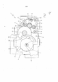
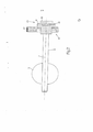
[008] A presente invenção será ora descrita com referência aos desenhos que acompanham, os quais ilustram um exemplo não limitativo de uma forma de realização desta, nos quais: - A figura 1 é uma vista frontal na forma de diagrama de uma válvula borboleta para um motor a combustão interna, com partes removidas por questão de clareza; - A figura 2 é uma vista lateral parcialmente seccionada do eixo da válvula borboleta da figura 1, feita de acordo com o método de manufatura, objeto da presente invenção; - A figura 3 é uma vista diagramática em perspectiva e em secção do eixo da figura 2; e - A figura 4 é uma vista diagramática em perspectiva de uma etapa de manufatura do eixo da figura 2.[008] The present invention will now be described with reference to the accompanying drawings, which illustrate a non-limiting example of an embodiment thereof, in which: - Figure 1 is a front view in the form of a diagram of a butterfly valve for an internal combustion engine, with parts removed for clarity; Figure 2 is a partially sectioned side view of the butterfly valve axis of Figure 1, made according to the manufacturing method, object of the present invention; - Figure 3 is a diagrammatic view in perspective and in section of the axis of figure 2; and - Figure 4 is a diagrammatic view in perspective of a manufacturing step on the axis of Figure 2.
[009] Na figura 1, o número 1 indica, no seu conjunto, uma válvula borboleta para um motor a combustão interna (não mostrado). A válvula borboleta 1 compreende um corpo de válvula 2 que acomoda um motor elétrico 3 e no qual é formada uma sede de válvula 4, a qual é engrenada por uma placa 5 da válvula borboleta (mostrada na figura 2), a qual é deslocada entre uma posição de abertura e uma posição de fechamento da sede de válvula 4 por efeito da ação do motor elétrico 3. Especificamente, a placa da válvula borboleta 5 é basculada sobre o eixo 6 que apresenta um eixo de rotação longitudinal 7 e a posição fechada, por efeito da ação do motor elétrico 3, é mecanicamente acoplada ao próprio eixo 6 por meio de um comando de engrenagens 8.[009] In figure 1, the number 1 indicates, as a whole, a butterfly valve for an internal combustion engine (not shown). The butterfly valve 1 comprises a
[0010] O motor elétrico 3 apresenta um corpo cilíndrico 9, o qual é delimitado, em sua base, por uma placa metálica 10 dotada de um par de furos passantes (não mostrados) atravessados por dois fios elétricos 11, os quais fornecem energia elétrica para o motor elétrico 3; uma correspondente bucha de isolamento 12 é disposta entre cada fio elétrico 11 e o correspondente furo (não mostrado) na placa 10. A função principal da placa 10 é a de permitir a fixação do motor elétrico 3 no corpo de válvula 2; para este propósito, a placa 10 apresenta três apêndices radiais perfurados 13, através dos quais passam os correspondentes parafusos de fixação 14 para o corpo da válvula 2.[0010] The
[0011] O motor elétrico 3 apresenta um eixo 15 que termina em uma roda dentada 16, a qual é mecanicamente acoplada ao eixo 6 por meio de uma rida dentada livre 17, interposta entre a roda dentada 16 e uma engrenagem terminal 18 integrada com o eixo 6. A roda dentada 17 apresenta um primeiro conjunto de dentes 19 acoplados com a roda dentada 16 e um segundo conjunto de dentes 20 acoplado com a engrenagem terminal 18; o diâmetro do primeiro conjunto de dentes 19 é diferente do diâmetro do segundo conjunto de dentes 20, assim a roda dentada 17 determina uma relação de transmissão não unitária. A engrenagem terminal 18 é definida por um corpo central totalmente cilíndrico 21, integral com o eixo 6 e dotado de uma poção de coroa circular 22, a qual apresenta uma série de dentes acoplados com a roda dentada 17. O comando totalmente composto por engrenagens 8, isto é, a roda dentada 16, a roda dentada 17 e a engrenagem terminal 18, é normalmente formado em material plástico.[0011] The
[0012] Tal como o quanto ilustrado através das figuras 1 e 2, a válvula borboleta 1 compreende um sensor de posição 23, o qual é acoplado ao eixo 6 e o qual está adaptado para detectar a posição angular da placa 5 da borboleta. O sensor de posição 23 é do tipo magnético sem contato e consiste de um magneto 24, integral em relação ao eixo 6, e de um dispositivo de leitura 25, disposto de frente ao magneto 24, para ler a posição angular do magneto 24. Especificamente, o magneto 24 apresenta um formato circular e é ao menos parcialmente inserido dentro do corpo central totalmente cilíndrico 21 de uma engrenagem terminal 18. Tal como o quanto ilustrado pelas figuras em anexo, o magneto 24 é parcialmente inserido dentro do corpo central totalmente cilíndrico 21 de uma engrenagem terminal 18, isto é, a parede de base do magneto 24 é visível e assim não recoberta pelo corpo central totalmente cilíndrico 21; de acordo com uma forma de realização diferente (não mostrada), o magneto 24 é completamente inserido dentro do corpo central totalmente cilíndrico 21 da engrenagem terminal 18, isto é, o magneto 24 é completamente encerrado dentro do corpo central totalmente cilíndrico 21.[0012] As shown in figures 1 and 2, the butterfly valve 1 comprises a position sensor 23, which is coupled to the
[0013] Tal como mostrado na figura 4, o eixo 6 e a engrenagem terminal 18 são formados juntos a partir de um material plástico (tecno polímeros) através de injeção; por conseqüência, o eixo 6 e a engrenagem terminal 18 são monolíticos, isto é, formado de modo inteiriço ou sem emendas pelo mesmo material. A manufatura do eixo 6 e da engrenagem terminal 18 contempla o uso de um primeiro molde 26, o qual reproduz o negativo do formato do eixo 6 e da engrenagem terminal 18 e, no qual, um material plástico fundido é injetado de modo a formar o eixo 6 e a engrenagem terminal 18. O primeiro molde 26 é conformado de modo a definir uma sede circular ou cavidade 28 na engrenagem terminal 18 destinada a uma posterior acomodação do magneto 24 do sensor de posição 23.[0013] As shown in figure 4, the
[0014] Em seguida, o eixo 6 e a engrenagem terminal 18 (ou apenas a engrenagem terminal 18) são ao menos parcialmente inseridos em um segundo molde 27, o qual reproduz o negativo do formato do magneto 24 do sensor de posição 23 e no qual um polímero magnético fundido (p. ex., um polímero de neodímio) é injetado de modo a formar o magneto 24. Obviamente, a segunda cavidade 27 abraça (envolve) a sede circular ou cavidade 28 destinada a acomodar o magneto 24 do sensor de posição 23. O polímero magnético consiste de pequenas partículas de material metálico magnético (pó) e de uma matriz de ligante plástico; de modo a injetar o polímero magnético, a matriz de ligante plástico é fundida, enquanto que as pequenas partículas de material metálico magnético (pó) permanecem sólidas e suspensas na matriz plástica fundida.[0014] Then, the
[0015] De acordo com uma forma preferida de realização, a injeção do polímero magnético plástico para formar o magneto 24 é realizada radialmente (isto é, perpendicular ao eixo de rotação radial 7) a partir de dois pontos de injeção diferentes e simetricamente dispostos ao redor do eixo de rotação longitudinal 7, e posicionados no perímetro externo da sede 28 para o magneto 24, de modo a otimizar a posição da linha uniforme de fluxo do material plástico, forçando-o dentro do volume do magneto 24. Em outras palavras, o polímero magnético fundido é injetado ao longo de uma direção radial a partir de pelo menos dois pontos de injeção diferentes, de modo a formar o magneto 24; o número de pontos de injeção é pelo menos igual a 2 e, de forma mais em geral, está compreendido entre dois e quatro. Em virtude do uso da injeção radial, a partir de diversos pontos de injeção diferentes, do polímero magnético fundido, as linhas contínuas ou inteiriças do magneto 24 ficam dispostas dentro do magneto 24 e assim o próprio magneto 24 fica particularmente homogêneo; devido a considerável homogeneidade do material injetado, as linhas de fluxo do campo magnético geradas pelo magneto 24, após a sua magnetização, são uniformes e assim a leitura da posição pelo sensor 23 é muito precisa.[0015] According to a preferred embodiment, the injection of the plastic magnetic polymer to form the
[0016] Por fim, o magneto 24 é magnetizado através da disposição do magneto dentro de um campo apropriadamente orientado e variando a intensidade do campo magnético, de modo a fazer com que o magneto 24 realize o ciclo de histerese. Normalmente, o magneto 24 é magnetizado após a injeção do próprio magneto 24; alternativamente, o magneto 24 poderia ser magnetizado durante a injeção, por exemplo, provendo o segundo molde 27 com uma bobina na qual uma corrente elétrica passasse com o uso.[0016] Finally, the
[0017] De acordo com uma forma possível de realização, dois moldes 26 e 27 apresentam uma peça comum 29 (isto é, que é usada tanto para o molde 26 quanto para o 27) e duas correspondentes partes características 30 e 31 (isto é, apropriada para cada molde 26 ou 27). Em outras palavras, o primeiro molde consiste de uma parte comum 29 e de uma parte característica apropriada 30, enquanto que o segundo molde 27 consiste de uma parte comum 28 e de uma parte característica apropriada 31.[0017] According to a possible embodiment, two
[0018] Em outras palavras, o eixo 6, a engrenagem terminal 18 e o magneto 24 são manufaturados através de uma injeção em duas etapas ou de uma injeção seqüencial de um material plástico de formação do eixo 6 e da engrenagem 18 e de um polímero magnético de formação do magneto 24.[0018] In other words,
[0019] No processo de manufatura supra descrito, o eixo 6 é inicialmente feito junto com a engrenagem 18 e o magneto 24 é feito posteriormente; de acordo com uma forma diversa de realização, o magneto 24 pode ser feito primeiro e a engrenagem terminal 18 depois.[0019] In the manufacturing process described above,
[0020] O método de manufatura supra descrito do eixo 6, da engrenagem terminal 18 e do magneto 24 é particularmente vantajoso uma vez que este permite restringir os tempos de manufatura e os custos, além de obter um componente altamente integrado e uma considerável precisão na manufatura, especificamente, no posicionamento do magneto 24 com relação ao eixo 6. Especificamente, a contenção dos tempos de manufatura e dos custos é obtida em virtude do fato de que o método supra descrito de manufatura do eixo 6, da engrenagem terminal 18 e do magneto 24 pode ser automatizado de forma simples e completa.[0020] The above-described manufacturing method of
[0021] O método de manufatura supra descrito obviamente pode ser usado para fabricar o conjunto eixo/rotor magnético para qualquer tipo de válvula de ajuste do fluxo de ar para um motor a combustão interna; por exemplo, um tal método de manufatura poderia ser usado para fabricar um conjunto eixo/rotor magnético de uma válvula de abafamento ou de afogador de um sistema de turbilhonamento ou de um sistema de inversão do coletor de admissão de um motor a combustão interna.[0021] The manufacturing method described above can obviously be used to manufacture the magnetic shaft / rotor assembly for any type of air flow adjustment valve for an internal combustion engine; for example, such a manufacturing method could be used to manufacture a magnetic shaft / rotor assembly of a choke or choke valve for a whirlwind system or an intake manifold reversing system for an internal combustion engine.
Claims (10)
Applications Claiming Priority (2)
| Application Number | Priority Date | Filing Date | Title |
|---|---|---|---|
| EP07425348.5 | 2007-06-04 | ||
| EP07425348A EP2000781B2 (en) | 2007-06-04 | 2007-06-04 | A manufacturing method of a shaft provided with a magnet for an air flow rate adjustment valve in an internal combustion engine |
Publications (2)
| Publication Number | Publication Date |
|---|---|
| BRPI0802196A2 BRPI0802196A2 (en) | 2009-04-07 |
| BRPI0802196B1 true BRPI0802196B1 (en) | 2020-10-27 |
Family
ID=38521163
Family Applications (1)
| Application Number | Title | Priority Date | Filing Date |
|---|---|---|---|
| BRPI0802196-1A BRPI0802196B1 (en) | 2007-06-04 | 2008-06-04 | axis manufacturing method |
Country Status (6)
| Country | Link |
|---|---|
| US (1) | US20080296804A1 (en) |
| EP (1) | EP2000781B2 (en) |
| CN (1) | CN101323161B (en) |
| AT (1) | ATE438839T1 (en) |
| BR (1) | BRPI0802196B1 (en) |
| DE (1) | DE602007001880D1 (en) |
Families Citing this family (7)
| Publication number | Priority date | Publication date | Assignee | Title |
|---|---|---|---|---|
| JP2011156664A (en) * | 2010-01-29 | 2011-08-18 | Showa Corp | Method and apparatus for manufacturing power transmission system molding |
| BR112014002889A2 (en) * | 2011-08-08 | 2017-03-01 | Husqvarna Ab | magnet holder for use in a choke position sensor and method of manufacture |
| DE102011119514B4 (en) * | 2011-11-26 | 2020-11-12 | Gm Tec Industries Holding Gmbh | Gear with permanently connected drive shaft |
| AU2013351120B2 (en) * | 2012-11-30 | 2016-08-11 | Petrolvalves S.P.A. | Continuous magnetic motion position indicator |
| DE202017106253U1 (en) * | 2017-10-16 | 2019-01-17 | Flaco-Geräte GmbH | Oval gear |
| CN110360012B (en) * | 2019-08-09 | 2024-08-09 | 马瑞利(中国)有限公司 | Electronic throttle output shaft assembly and manufacturing method |
| JP2022012529A (en) * | 2020-07-01 | 2022-01-17 | 株式会社デンソー | Rotatable component and method for manufacturing rotatable component |
Family Cites Families (13)
| Publication number | Priority date | Publication date | Assignee | Title |
|---|---|---|---|---|
| US4327346A (en) * | 1979-02-28 | 1982-04-27 | Tdk Electronics Co., Ltd. | Anisotropic polymeric magnet in the tubular form and process for producing the same |
| US4364011A (en) * | 1979-05-16 | 1982-12-14 | Ransome Hoffmann Pollard Ltd. | Mechanical assemblies employing sensing means for sensing motion or position |
| FR2583514B1 (en) * | 1985-06-18 | 1990-04-20 | Peugeot | DEVICE FOR MARKING A MOVING PART USING MAGNETIC PLASTICS AND ITS MANUFACTURING METHOD |
| US5427514A (en) * | 1988-04-28 | 1995-06-27 | Yazaki Corporation | Magnetic plastic rotor disk manufacturing apparatus |
| EP1024267A3 (en) * | 1999-01-29 | 2003-08-06 | AB Elektronik GmbH | Throttle valve rotation angle sensor |
| US6288534B1 (en) * | 1999-02-10 | 2001-09-11 | Cts Corporation | Non-contacting throttle valve position sensor |
| US6278269B1 (en) * | 1999-03-08 | 2001-08-21 | Allegro Microsystems, Inc. | Magnet structure |
| US6498311B1 (en) * | 2001-06-29 | 2002-12-24 | Microsoft Corporation | Multi-layer keys with translucent outer layer |
| DE10137771A1 (en) † | 2001-08-02 | 2003-02-20 | Bosch Gmbh Robert | Throttle valve unit with integrated throttle valve |
| JP2003130045A (en) * | 2001-10-25 | 2003-05-08 | Pentax Corp | Bearing structure |
| JP2005048671A (en) * | 2003-07-29 | 2005-02-24 | Mitsubishi Electric Corp | Engine intake control system |
| JP3983722B2 (en) * | 2003-08-04 | 2007-09-26 | 三菱電機株式会社 | Engine intake control device |
| DE102004020734A1 (en) † | 2004-04-27 | 2005-11-24 | Windhorst Beteiligungsgesellschaft Mbh | Measuring system for angular positions based on magnets uses a magneto-resistive sensor to detect permanent magnet field components in interlinked bridge circuits |
-
2007
- 2007-06-04 AT AT07425348T patent/ATE438839T1/en not_active IP Right Cessation
- 2007-06-04 DE DE602007001880T patent/DE602007001880D1/en active Active
- 2007-06-04 EP EP07425348A patent/EP2000781B2/en active Active
-
2008
- 2008-06-04 CN CN2008101099127A patent/CN101323161B/en active Active
- 2008-06-04 BR BRPI0802196-1A patent/BRPI0802196B1/en active IP Right Grant
- 2008-06-04 US US12/133,235 patent/US20080296804A1/en not_active Abandoned
Also Published As
| Publication number | Publication date |
|---|---|
| EP2000781A1 (en) | 2008-12-10 |
| CN101323161B (en) | 2012-10-24 |
| ATE438839T1 (en) | 2009-08-15 |
| EP2000781B2 (en) | 2013-03-13 |
| DE602007001880D1 (en) | 2009-09-17 |
| CN101323161A (en) | 2008-12-17 |
| US20080296804A1 (en) | 2008-12-04 |
| BRPI0802196A2 (en) | 2009-04-07 |
| EP2000781B1 (en) | 2009-08-05 |
Similar Documents
| Publication | Publication Date | Title |
|---|---|---|
| BRPI0802257B1 (en) | axis manufacturing method | |
| BRPI0802196B1 (en) | axis manufacturing method | |
| JP5496924B2 (en) | Method for manufacturing insert molded product, insert nut, pin member, and insert molded product | |
| US8635986B2 (en) | Rotation angle sensors | |
| JP4192716B2 (en) | Method of manufacturing throttle device for internal combustion engine | |
| JP5225966B2 (en) | Method of manufacturing rotation angle detection device | |
| JP2008298083A (en) | Method of adjusting opening of throttle body opener | |
| JP4103721B2 (en) | Method of forming throttle device for internal combustion engine | |
| JP2005054627A (en) | Throttle body | |
| CN103022775B (en) | Terminal-supporting apparatus | |
| JP6070242B2 (en) | Method for producing insert resin molded body | |
| BR0303819B1 (en) | Production method for the rotor component of a position sensor of a butterfly valve for internal combustion engine. | |
| JP4767765B2 (en) | Rotation angle sensor, rotation angle sensor forming method and throttle opening control device | |
| US20140043020A1 (en) | Rotator for an angle sensor | |
| JP2015081510A (en) | Air intake system | |
| US6325045B1 (en) | Device for controlling intake air quantity of combustion engine and a method of producing the same | |
| JP2011102770A (en) | Rotation angle detector and throttle controller | |
| JP5329367B2 (en) | Rotation angle detection device, manufacturing method thereof, and throttle control device | |
| CN108397558A (en) | A kind of high cooperation precision electric valve | |
| JPH07167674A (en) | Rotation angle sensor | |
| JP2010106690A (en) | Valve unit and method for manufacturing the same | |
| JP2021167094A (en) | Motor manufacturing method | |
| JP2010116795A (en) | Intake device for internal combustion engine | |
| CN208826971U (en) | A kind of precision rotor injection forming mold | |
| JP2012224048A (en) | Injection molding method |
Legal Events
| Date | Code | Title | Description |
|---|---|---|---|
| B03A | Publication of a patent application or of a certificate of addition of invention [chapter 3.1 patent gazette] | ||
| B06T | Formal requirements before examination [chapter 6.20 patent gazette] | ||
| B06F | Objections, documents and/or translations needed after an examination request according [chapter 6.6 patent gazette] | ||
| B09A | Decision: intention to grant [chapter 9.1 patent gazette] | ||
| B16A | Patent or certificate of addition of invention granted [chapter 16.1 patent gazette] |
Free format text: PRAZO DE VALIDADE: 10 (DEZ) ANOS CONTADOS A PARTIR DE 27/10/2020, OBSERVADAS AS CONDICOES LEGAIS. |