BRPI0803577B1 - MOTORCYCLE INTERLOCK BRAKE DEVICE - Google Patents
MOTORCYCLE INTERLOCK BRAKE DEVICE Download PDFInfo
- Publication number
- BRPI0803577B1 BRPI0803577B1 BRPI0803577-6A BRPI0803577A BRPI0803577B1 BR PI0803577 B1 BRPI0803577 B1 BR PI0803577B1 BR PI0803577 A BRPI0803577 A BR PI0803577A BR PI0803577 B1 BRPI0803577 B1 BR PI0803577B1
- Authority
- BR
- Brazil
- Prior art keywords
- brake
- pressure
- pressure regulator
- master cylinder
- motorcycle
- Prior art date
Links
- 239000002184 metal Substances 0.000 claims description 8
- 230000002093 peripheral effect Effects 0.000 abstract description 11
- 239000000470 constituent Substances 0.000 abstract description 10
- 230000001105 regulatory effect Effects 0.000 description 28
- 230000006835 compression Effects 0.000 description 23
- 238000007906 compression Methods 0.000 description 23
- 238000003780 insertion Methods 0.000 description 6
- 230000037431 insertion Effects 0.000 description 6
- 230000003247 decreasing effect Effects 0.000 description 4
- 230000002787 reinforcement Effects 0.000 description 2
- 235000008733 Citrus aurantifolia Nutrition 0.000 description 1
- 229910000831 Steel Inorganic materials 0.000 description 1
- 235000011941 Tilia x europaea Nutrition 0.000 description 1
- 239000006096 absorbing agent Substances 0.000 description 1
- 230000005540 biological transmission Effects 0.000 description 1
- 230000001276 controlling effect Effects 0.000 description 1
- 239000000446 fuel Substances 0.000 description 1
- 239000004571 lime Substances 0.000 description 1
- 239000007788 liquid Substances 0.000 description 1
- 239000000203 mixture Substances 0.000 description 1
- 230000035939 shock Effects 0.000 description 1
- 238000009751 slip forming Methods 0.000 description 1
- 239000010959 steel Substances 0.000 description 1
- 239000000725 suspension Substances 0.000 description 1
- 238000003466 welding Methods 0.000 description 1
Images


Landscapes
- Hydraulic Control Valves For Brake Systems (AREA)
- Braking Arrangements (AREA)
- Motorcycle And Bicycle Frame (AREA)
- Transmission Of Braking Force In Braking Systems (AREA)
Abstract
dispositivo de freio de intertravamento de motocicleta. a presente invenção refere-se a um dispositivo de freio de intertravamento (50) de uma motocicleta (10) que pode montar facilmente os respectivos componentes constituintes do dispositivo de freio de intertravamento (50) em uma maneira compacta ao mesmo tempo em que assegura um intervalo entre os respectivos componentes constituintes e os componentes periféricos. em um dispositivo de freio de intertravamento (50) de uma motocicleta (10) que inclui um freio traseiro hidráulico (52), um cilindro mestre traseiro (61) para suprir pressão de óleo correspondente a uma manipulação de freio de um motociclista para o freio traseiro (52), e um regulador de pressão (62) para regular a pressão de óleo do cilindro mestre traseiro (61) e para suprir pressão de óleo para um freio dianteiro hidráulico (53), o cilindro mestre traseiro (61) e o regulador de pressão (62) sendo integralmente montados em um dispositivo de freio de intertravamento (50), o regulador de pressão (62) está disposto dentro do cilindro mestre traseiro (61) na direção da largura do veículo e acima de uma variação (h) oscilante de um braço oscilante (24) que sustenta oscilante e articuladamente uma roda traseira (rw) do veículo (10).motorcycle interlock brake device. the present invention relates to an interlocking brake device (50) of a motorcycle (10) that can easily assemble the respective constituent components of the interlocking brake device (50) in a compact manner while ensuring a gap between the respective constituent components and the peripheral components. on a motorcycle interlock brake device (50) (10) that includes a hydraulic rear brake (52), a rear master cylinder (61) to supply oil pressure corresponding to a motorcycle rider's brake handling for the brake rear (52), and a pressure regulator (62) to regulate the oil pressure of the rear master cylinder (61) and to supply oil pressure for a hydraulic front brake (53), the rear master cylinder (61) and the pressure regulator (62) being integrally mounted on an interlocking brake device (50), the pressure regulator (62) is arranged inside the rear master cylinder (61) in the direction of the vehicle width and above a variation (h ) swinging from a swinging arm (24) that swing and swing a rear wheel (rw) of the vehicle (10).
Description
[0001] A presente invenção refere-se a um dispositivo de freio de intertravamento de uma motocicleta e mais particularmente a um dispositivo de freio de intertravamento de uma motocicleta que inclui um cilindro mestre do tipo integral regulador de pressão que é integralmente formado de um regulador de pressão e de um cilindro mestre traseiro.[0001] The present invention relates to a motorcycle interlock brake device and more particularly to a motorcycle interlock brake device that includes a master cylinder of the integral pressure regulator type which is integrally formed of a regulator pressure and a rear master cylinder.
[0002] Como um dispositivo de freio de intertravamento convencional de uma motocicleta, tem sido conhecida a estrutura na qual um regulador de pressão e um cilindro mestre traseiro são integralmente formados paralelos um ao outro, (por exemplo, vide o Documento de Patente 1).[0002] As a conventional motorcycle interlock brake device, the structure in which a throttle and rear master cylinder are integrally formed parallel to each other has been known (for example, see Patent Document 1) .
[0003] Documento de Patente 1: Patente Japonesa N° 3270194[0003] Patent Document 1: Japanese Patent No. 3270194
[0004] Aqui, uma parte de manipulação e uma parte de operação de um dispositivo de freio de intertravamento de uma motocicleta estão dispostas em partes respectivas do veículo em uma maneira distribuída por motivos funcionais. Assim, na disposição dos respectivos componentes constituintes do dispositivo de freio de intertravamento nas respectivas partes do veículo, é necessária uma disposição dos respectivos componentes constituintes em uma maneira compacta e de montagem fácil, ao mesmo tempo em que assegura um intervalo entre os respectivos componentes constituintes e os componentes do chassi ou similares. Além disso, apesar de uma rota de freio para suprir óleo de funcionamento para a parte de operação proveniente da parte de manipulação ser alongada, é necessária uma disposição da rota de freio de maneira a obter alta fluidez de frenagem ao mesmo tempo em que assegura um intervalo entre a rota de freio e os componentes periféricos. Contudo, com relação ao dispositivo de freio de intertravamento da motocicleta descrito no Documento de Patente 1, apesar de estarem descritos os respectivos componentes constituintes do dispositivo de freio de intertravamento, não estão descritas a estrutura específica e a disposição de mangueira específica para verdadeiramente dispor os respectivos componentes constituintes em um corpo de veículo.[0004] Here, a handling part and an operating part of a motorcycle interlocking brake device are arranged in respective parts of the vehicle in a distributed manner for functional reasons. Thus, in the arrangement of the respective constituent components of the interlocking brake device in the respective parts of the vehicle, an arrangement of the respective constituent components is required in a compact and easily assembled manner, while ensuring an interval between the respective constituent components and chassis components or the like. In addition, although a brake route for supplying operating oil to the operating part from the handling part is lengthened, an arrangement of the brake route is necessary in order to obtain high braking fluidity while ensuring a gap between the brake route and the peripheral components. However, with respect to the motorcycle interlocking brake device described in Patent Document 1, although the respective constituent components of the interlocking brake device are described, the specific structure and specific hose arrangement are not described to truly dispose of the respective constituent components in a vehicle body.
[0005] A presente invenção foi feita sob tais circunstâncias e é um objetivo da mesma proporcionar um dispositivo de freio de intertravamento de uma motocicleta que possa facilmente montar os respectivos elementos constituintes do dispositivo de freio de intertravamento de maneira compacta ao mesmo tempo em que assegura um intervalo entre os respectivos elementos constituintes e os componentes periféricos.[0005] The present invention was made under such circumstances and it is an object of the same to provide a motorcycle interlocking brake device that can easily assemble the respective constituent elements of the interlocking brake device in a compact manner while ensuring an interval between the respective constituent elements and the peripheral components.
[0006] Para alcançar o supracitado objetivo, a invenção descrita na reivindicação 1 é caracterizada pelo fato de que, em um dispositivo de freio de intertravamento de uma motocicleta compreendendo um freio traseiro hidráulico, um cilindro mestre traseiro para suprir pressão de óleo correspondente a uma manipulação de freio de um motociclista para o freio traseiro e um regulador de pressão para regular a pressão do óleo do cilindro mestre traseiro e para suprir pressão óleo para um freio dianteiro hidráulico e o cilindro mestre traseiro e o regulador de pressão sendo integralmente montados no dispositivo de freio de intertravamento, o regulador de pressão está disposto dentro do cilindro mestre traseiro na direção da largura do veículo e acima de uma variação oscilante de um braço oscilante que sustenta oscilante e giratoriamente uma roda traseira do veículo.[0006] To achieve the aforementioned objective, the invention described in claim 1 is characterized by the fact that, in a motorcycle interlock brake device comprising a hydraulic rear brake, a rear master cylinder to supply oil pressure corresponding to a a motorcycle rider's handling of the rear brake and a pressure regulator to regulate the oil pressure of the rear master cylinder and to supply oil pressure to a hydraulic front brake and the rear master cylinder and pressure regulator being integrally mounted on the device interlocking brake, the pressure regulator is arranged inside the rear master cylinder in the direction of the vehicle width and above an oscillating variation of an oscillating arm that pivots and rotates a vehicle's rear wheel.
[0007] A invenção descrita na reivindicação 2 é, além da constituição da invenção descrita na reivindicação 1, caracterizada pelo fato de que a armação do corpo do veículo inclui um membro de retenção no estribo do assento traseiro, e um cilindro mestre do tipo integral regulador de pressão que é integralmente formado do cilindro mestre traseiro e do regulador de pressão está montado no membro de retenção no estribo do assento traseiro.[0007] The invention described in
[0008] A invenção descrita na reivindicação 3 é, além da constituição da invenção descrita na reivindicação 1 ou na reivindicação 2, caracterizada pelo fato de que o dispositivo de freio de intertravamento também inclui uma rota de freio traseiro que conecta o regulador de pressão e o freio traseiro e uma rota de freio de intertravamento que conecta o regulador de pressão de o freio dianteiro, e os orifícios de suprimento de pressão e óleo para conectar a rota de freio traseiro e a rota de freio de intertravamento para o regulador de pressão serem formados no regulador de pressão em um estado que os orifícios de suprimento de pressão de óleo são direcionados para dentro da motocicleta na direção da largura do veículo.[0008] The invention described in claim 3 is, in addition to the constitution of the invention described in claim 1 or
[0009] A invenção descrita na reivindicação 4 é, além da constituição da invenção descrita em qualquer uma das reivindicações 1 a 3, a rota de freio de intertravamento inclui uma mangueira elástica traseira conectada ao regulador de pressão, um tubo intermediário feito de metal conectado à mangueira elástica traseira e uma mangueira elástica dianteira para o tubo intermediário, e uma parte conectada do tubo intermediário e a mangueira elástica dianteira está disposta na frente de um tubo frontal da motocicleta e na proximidade do centro na direção da largura do veículo.[0009] The invention described in
[00010] De acordo com o dispositivo de freio de intertravamento da motocicleta descrito na reivindicação 1, o cilindro mestre traseiro para suprir pressão de óleo correspondente a uma manipulação de freio de um motociclista para o freio traseiro e o regulador de pressão para regular a pressão do óleo do cilindro mestre traseiro e para suprir pressão de óleo para o freio dianteiro hidráulico são integralmente montados no dispositivo de freio de intertravamento, e o regulador de pressão está disposto dentro do cilindro mestre traseiro na direção da largura do veículo e acima da faixa oscilante do braço oscilante que sustenta oscilante e giratoriamente a roda traseira do veículo e, portanto, é possível facilmente montar os respectivos componentes constituintes do dispositivo de freio de intertravamento no corpo do veículo de maneira compacta ao mesmo tempo em que assegura um intervalo entre os componentes constituintes e os componentes periféricos.[00010] According to the motorcycle interlocking brake device described in claim 1, the rear master cylinder for supplying oil pressure corresponding to a motorcyclist's brake handling for the rear brake and the pressure regulator to regulate the pressure of the oil from the rear master cylinder and to supply oil pressure to the hydraulic front brake are integrally mounted on the interlocking brake device, and the pressure regulator is arranged inside the rear master cylinder in the direction of the vehicle width and above the oscillating range of the swing arm that swings the rear wheel of the vehicle oscillating and rotating and therefore it is possible to easily assemble the respective components of the interlocking brake device in the vehicle body in a compact manner while ensuring an interval between the constituent components and peripheral components.
[00011] De acordo com o dispositivo de freio de intertravamento de motocicleta descrito na reivindicação 2, a armação do corpo do veículo do veículo inclui o membro de retenção de estribo de assento traseiro, e o cilindro mestre do tipo integral regulador de pressão que é integralmente formado do cilindro mestre traseiro e o regulador de pressão está montado no membro de retenção de estribo de assento traseiro e, portanto, é possível facilmente montar o cilindro mestre do tipo integral regulador de pressão no corpo do veículo em uma maneira compacta ao mesmo tempo em que evita a interferência o cilindro mestre com o braço oscilante que é oscilado juntamente com a movimentação do veículo.[00011] According to the motorcycle interlock brake device described in
[00012] De acordo com o dispositivo de freio de intertravamento de motocicleta descrito na reivindicação 3, o dispositivo de freio de intertravamento inclui a rota de freio traseiro que conecta o regulador de pressão e o freio traseiro e a rota de freio de intertravamento que conecta o regulador de pressão e o freio dianteiro, e os orifícios de suprimento de pressão de óleo para conectar a rota de freio traseiro e a rota de freio de intertravamento para o regulador de pressão são respectivamente formados no regulador de pressão em um estado que os orifícios de suprimento de pressão de óleo são direcionados para dentro da motocicleta na direção da largura do veículo e, portanto, é possível encurtar as extensões das respectivas rotas de freio a partir do regulador de pressão para o freio dianteiro e para o freio traseiro respectivamente. Além disso, a disposição das respectivas rotas de freio pode ser facilmente realizada ao mesmo tempo em que assegura o intervalo entre as rotas de freio e os componentes periféricos e, portanto, é possível aperfeiçoar a aparência da motocicleta.[00012] According to the motorcycle interlock brake device described in claim 3, the interlock brake device includes the rear brake route that connects the throttle and the rear brake and the interlock brake route that connects the pressure regulator and the front brake, and the oil pressure supply holes for connecting the rear brake route and the interlocking brake route for the pressure regulator are respectively formed in the pressure regulator in a state that the holes oil pressure supplies are directed into the motorcycle towards the width of the vehicle and, therefore, it is possible to shorten the lengths of the respective brake routes from the pressure regulator to the front brake and the rear brake respectively. In addition, the arrangement of the respective brake routes can be easily carried out while ensuring the interval between the brake routes and the peripheral components and, therefore, it is possible to improve the appearance of the motorcycle.
[00013] De acordo com o dispositivo de freio de intertravamento de motocicleta descrito na reivindicação 4, a rota de freio de intertravamento inclui a mangueira elástica traseira conectada ao regulador de pressão, o tubo intermediário feito de metal conectado à mangueira elástica traseira e à mangueira elástica dianteira conectadas ao tubo intermediário, e a parte e conexão do tub intermediário e a mangueira elástica dianteira está disposta em frente ao tubo frontal da motocicleta e na proximidade do centro na direção da largura do veículo e, portanto, é possível dispor a rota de freio de intertravamento ao mesmo tempo em que assegura um intervalo entre um grupo de mangueiras da rota de freio de intertravamento e os componentes periféricos tal qual um farol no momento de direção de um manípulo. Ademais, o tubo intermediário feito de metal está disposto entre a mangueira elástica traseira e a mangueira elástica dianteira e, portanto, é possível obter a alta rigidez do freio.[00013] According to the motorcycle interlock brake device described in
[00014] Nas partes que se seguem, a explicação é feita em detalhes com relação a uma modalidade de um dispositivo de freio de intertravamento de uma motocicleta de acordo com a presente invenção juntamente com os desenhos em anexo. Aqui, os desenhos são vistos na direção dos números.[00014] In the following parts, the explanation is given in detail with respect to a modality of a motorcycle interlocking brake device according to the present invention together with the attached drawings. Here, the drawings are seen in the direction of the numbers.
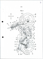
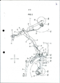
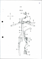
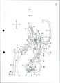
[00015] A figura 1 é uma vista lateral da uma motocicleta na qual um dispositivo de freio de intertravamento de uma motocicleta de acordo com a presente invenção é montada, a Figura 2 é uma vista lateral para explicar toda a constituição do dispositivo de freio de intertravamento, a Figura 3 é uma vista plana para explicar toda a constituição do dispositivo de freio de intertravamento, a Figura 4 é uma vista ampliada de uma parte essencial para explicar uma posição de disposição de um cilindro mestre do tipo integral regulador de pressão, a Figura 5 é uma vista em perspectiva do cilindro mestre do tipo integral regulador de pressão montado em um retentor de estribo de assento traseiro conforme visto da face esquerda e dianteira do corpo do veículo, a Figura 6 é uma vista plana do cilindro mestre do tipo integral regulador de pressão ilustrado na Figura 5, conforme visto de cima, a Figura 7 é uma vista em corte transversal tomada ao longo da linha A-A na figura 4, a Figura 8 é uma vista em corte transversal ampliada de uma parte essencial para explicar uma operação do cilindro mestre do tipo integral regulador de pressão, a Figura 9 é um gráfico ilustrando uma curva característica do regulador de pressão, a Figura 10 é uma vista plana com uma parte interrompida longe do mecanismo de freio dianteiro montado em uma alavanca conforme visto de cima, a Figura 11 é uma vista posterior com uma parte interrompida longe do mecanismo de freio dianteiro ilustrado na Figura 10, conforme visto debaixo, e a Figura 12 é uma vista frontal do mecanismo de freio ilustrado na Figura 10, conforme visto de uma lateral frontal. Aqui, na explicação feita nas partes que se seguem, as direções para frente e para trás, nas direções para a esquerda e para a direita, e as direções ascendente e descendente correspondendo às direções conforme vistas a partir de um motociclista e a direção para frente é indicada pelo símbolo Fr, a direção para trás é indicada pelo símbolo Rr, e a direção para a esquerda é indicada pelo símbolo L, a direção para a direita é indicada pelo símbolo R, e a direção ascendente é indicada pelo símbolo U, e a direção descendente é indicada pelo símbolo D.[00015] Figure 1 is a side view of a motorcycle on which a motorcycle interlocking brake device according to the present invention is mounted, Figure 2 is a side view to explain the entire constitution of the motorcycle brake device. interlocking, Figure 3 is a plan view to explain the entire constitution of the interlocking brake device, Figure 4 is an enlarged view of an essential part to explain a disposition position of a master cylinder of the integral pressure regulator type, the Figure 5 is a perspective view of the pressure regulator integral type master cylinder mounted on a rear seat stirrup retainer as seen from the left and front face of the vehicle body, Figure 6 is a plan view of the integral type master cylinder pressure regulator illustrated in Figure 5, as seen from above, Figure 7 is a cross-sectional view taken along line AA in Figure 4, Figure 8 is a view in enlarged cross-section of an essential part to explain an operation of the master cylinder of the integral pressure regulator type, Figure 9 is a graph illustrating a characteristic curve of the pressure regulator, Figure 10 is a plan view with an interrupted part away from the front brake mechanism mounted on a lever as seen from above, Figure 11 is a rear view with a broken part away from the front brake mechanism shown in Figure 10, as seen from below, and Figure 12 is a front view of the brake illustrated in Figure 10, as seen from a front side. Here, in the explanation made in the following parts, the forward and backward directions, in the left and right directions, and the up and down directions corresponding to the directions as seen from a motorcyclist and the forward direction. is indicated by the Fr symbol, the backward direction is indicated by the Rr symbol, and the left direction is indicated by the L symbol, the right direction is indicated by the R symbol, and the upward direction is indicated by the U symbol, and the downward direction is indicated by the symbol D.
[00016] Conforme ilustrado na figura 1, a motocicleta 10 dessa modalidade inclui uma armação de corpo de veículo 11. Conforme ilustrado na Figura 2 e na Figura 3, a armação de corpo de veículo 11 inclui um tubo frontal 13 que sustenta giratoriamente um garfo dianteiro 12, uma armação principal 14 que se estende para trás e para baixo a partir do tubo frontal 13, um par de chapas de pivô esquerdo e direito 15 que é unido a uma parte traseira da armação principal 14 e se estende para baixo, um par de armações traseiras esquerda e direita 16 que é unido às superfície laterais traseiras da armação principal 14 e se estende para trás e para cima, uma armação de reforço 17 que conecta uma parte de extremidade traseira da armação principal 14 e uma parte intermediária da armação traseira 16, e membros de retenção de estribo de assento traseiro 18 que são montados nas superfícies laterais das chapas de pivô 15. Aqui, os membros respectivos acima mencionados da armação do corpo de veículo 11 estão unidos um ao outro por soldagem ou similar.[00016] As shown in figure 1, the motorcycle 10 of this modality includes a vehicle body frame 11. As shown in Figure 2 and Figure 3, the vehicle body frame 11 includes a front tube 13 that swivelly supports a
[00017] Uma roda dianteira FW é sustentada articuladamente em uma parte de extremidade inferior de um garfo dianteiro 12 e uma alavanca 21 está montada em uma parte de extremidade superior do garfo dianteiro 12. Além disso, um para-lama dianteiro 22 que cobre a roda dianteira FW a partir de cima está montada no garfo dianteiro 12.[00017] An FW front wheel is pivotally supported on a lower end part of a
[00018] Um braço de oscilação 24 que sustenta articuladamente uma roda traseira RW é sustentado oscilante no par de chapas de pivô esquerdo e direito 15 por meio de um eixo de articulação 23. Ademais, os absorventes de choque traseiros 25 estão dispostos entre a armação traseira 16 da armação de corpo de veículo 11 e uma parte de extremidade traseira do braço de oscilação 24.[00018] A
[00019] Uma unidade de força P que é integralmente constituída de um motor E e uma transmissão M está disposta abaixo da armação principal 14, e a unidade de força P é sustentada em chapas suspensoras 26 montadas em uma parte intermediária da armação principal 14 e as chapas de pivô 15.[00019] A power unit P which is integrally constituted by an E motor and a transmission M is arranged below the
[00020] Um corpo de válvula 28 que ajusta uma quantidade de suprimento de uma mistura de combustível e ar para o motor E é conectado a uma parede lateral superior de uma cabeça de cilindro 27 do motor E, e um filtro de ar 29 que purifica a entrada de ar está conectado a uma extremidade contra a corrente do corpo de válvula 28. Além disso, um tubo de exaustão 30 está conectado a uma parede lateral inferior de uma cabeça de cilindro 27.[00020] A valve body 28 that adjusts a supply amount of a mixture of fuel and air to the E engine is connected to an upper side wall of a cylinder head 27 of the E engine, and an
[00021] Aqui, na figura 1, o número 31 indica uma cobertura lateral dianteira, o número 32 indica uma proteção de perna, o número 33 indica uma cobertura dianteira, o número 34 indica uma cobertura interna, o número 35 indica uma cobertura lateral traseira, o número 36 indica um para-lama traseiro, o número 37 indica um assento, o número 38 indica um trilho de agarrar, o numeral 39 indica um farol dianteiro, o número 40 indica uma lâmpada de freio, o número 41 indica um pedal de freio e o número 43 indica um estribo de assento.[00021] Here, in figure 1, the number 31 indicates a front side cover, the number 32 indicates a leg cover, the
[00022] Ademais, nessa modalidade, conforme ilustrado na Figura 2 a Figura 6, um dispositivo de freio de intertravamento 50 está montado na motocicleta 10. O dispositivo de freio de intertravamento 50 inclui um cilindro mestre do tipo integral regulador de pressão 51, um freio traseiro hidráulico tipo disco 52 que confere uma força de frenagem à roda traseira RW, um freio dianteiro hidráulico tipo disco 53 que confere uma força de frenagem à roda dianteira FW, uma rota de freio traseiro 54 que supre óleo de funcionamento ao freio traseiro 52 e uma rota de freio de intertravamento 55 que supre óleo de funcionamento para o freio dianteiro 53.[00022] Furthermore, in this modality, as shown in Figure 2 to Figure 6, an
[00023] Conforme ilustrado na Figura 5 e na figura 6, o cilindro mestre do tipo integral regulador de pressão 51 é integralmente formado de um cilindro mestre traseiro 61 e um regulador de pressão em um estado que o cilindro mestre traseiro 61 e o regulador de pressão 62 estão dispostos em paralelo um ao outro, e está fixado em uma lateral interna do membro de retenção estribo de assento traseiro 18 na direção da largura do veículo por um pino 63. Além disso, o regulador de pressão 62 está disposto acima do cilindro mestre traseiro 61 em uma maneira deslocada. Ademais, o regulador de pressão 62 está disposto acima de uma variação oscilante H (vide Figura 7) do braço de oscilação 24. Consequentemente, mesmo quando o braço de oscilação 24 é oscilado para cima e para baixo juntamente com o funcionamento da motocicleta 10, não há a possibilidade do braço de oscilação 24 interferir com o regulador de pressão 62. Aqui, a estrutura e a maneira de operação do cilindro mestre do tipo integral regulador de pressão 51 estão descritos em detalhes posteriormente.[00023] As illustrated in Figure 5 and Figure 6, the master cylinder of the integral
[00024] Ademais, os orifícios de suprimento de pressão de óleo 64, 65 para conectar a rota de freio traseiro 54 e a rota de freio de intertravamento 55 para o regulador de pressão 62 são formados no regulador de pressão 62 em um estado que os orifícios de suprimento de pressão de óleo 64, 65 são respectivamente direcionados para dentro da motocicleta 10 na direção da largura do veículo. Além disso, um tanque reservatório 67 que está fixado na armação traseira 16 está conectado ao cilindro mestre traseiro 61 por meio de uma mangueira 66.[00024] In addition, the oil
[00025] Um pedal de freio 41 é sustentado oscilante e articuladamente em uma parte de extremidade inferior de uma chapa de pivô 15 em uma face direita do corpo do veículo, e uma alavanca 41a formada em uma parte de extremidade traseira do pedal de freio 41 está ligada a um pistão 70 do cilindro mestre traseiro 61 por meio de um esteio de ligação 68 e de uma haste de conexão 69.[00025] A
[00026] Por exemplo, a rota de freio traseiro 54 é formada de uma mangueira elástica feita de borracha resistente à pressão, e conecta o orifício de suprimento de óleo 64 do regulador de pressão 62 e um calibrador de freio traseiro 52a do freio traseiro 52. O calibrador de freio traseiro 52a é acionado por óleo de funcionamento suprido da rota de freio traseiro 54, e confere uma força de frenagem à roda traseira RW pela retenção de um rotor de freio traseiro 52b fixado à roda traseira RW. Além disso, uma parte intermediária da rota de freio traseiro 54 é fixada ao braço de oscilação 24 usando os membros de fixação 71, 71.[00026] For example, the
[00027] A rota de freio de intertravamento 55 inclui uma mangueira elástica traseira 72 conectada ao orifício de suprimento de pressão de óleo 65 do regulador de pressão 62, um tubo intermediário feito de metal 73 conectado à mangueira elástica traseira 72, e uma mangueira elástica dianteira 74 conectada ao tubo intermediário 73. A rota de freio intermediaria 55 conecta o orifício de suprimento de pressão de óleo 65 do regulador de pressão 62 e um mecanismo de freio dianteiro 110 do freio dianteiro 53 descrito posteriormente. Além disso, um calibrador de freio dianteiro 53a está conectado ao mecanismo de freio dianteiro 110 por meio de uma mangueira de freio 75. O calibrador de freio dianteiro 53a é acionado pelo óleo de funcionamento suprido da mangueira de freio 75 e confere uma força de frenagem à roda dianteira FW pela retenção de um rotor de freio dianteiro 53b fixado na roda dianteira FW.[00027]
[00028] Além disso, por exemplo, a mangueira elástica traseira 72, a mangueira elástica dianteira 74 e a mangueira de freio 75 são formadas de uma mangueira feita de borracha resistente à pressão, e essas mangueiras são flexíveis. Ademais por exemplo, o tubo intermediário 73 é formado de um tubo de aço. O tubo intermediário 73 se estende para frente ao longo da armação principal 14 a partir de uma lateral dianteira e disposta em um estado que o tubo intermediário 73 avança sobre a armação principal 14 a partir da face direita para a face esquerda.[00028] In addition, for example, the rear
[00029] Aqui, uma extensão total da rota de freio de intertravamento 55 é alongada para introduzir óleo de funcionamento para o freio dianteiro 53 a partir do cilindro mestre do tipo integral regulador de pressão 51 disposto no centro substancialmente do corpo do veículo. Por exemplo, quando toda a rota é constituída de mangueira elástica, existe a possibilidade de que a mangueira elástica se expanda devido à pressão do óleo de funcionamento, portanto, ocasionando o surgimento do inconveniente de que a rigidez do freio se torne insuficiente. Contudo, nessa modalidade, o tubo intermediário feito de metal 73 sendo dotado de alta rigidez é usado para formar uma parte da rota de freio de intertravamento 55 e, portanto, a rota de freio de intertravamento pode obter rigidez de freio alta.[00029] Here, a total length of the interlocking
[00030] Além disso, nessa modalidade, uma parte de conexão 76 entre o tubo intermediário 73 e a mangueira elástica dianteira 74 está disposta em frente ao tubo frontal 13 da armação do corpo do veículo 11 e na proximidade do centro na direção da largura do veículo. Consequentemente, é possível impedir a interferência entre a rota de freio de intertravamento 55 e os componentes periféricos como, por exemplo, o farol dianteiro 39 quando a alavanca está direcionada.[00030] Furthermore, in this embodiment, a
[00031] A seguir, em combinação com a Figura 7 a Figura 9, serão explicadas em detalhe a constituição e a maneira de operação do cilindro mestre do tipo integral regulador de pressão 51.[00031] Next, in combination with Figure 7 to Figure 9, the constitution and operation of the master cylinder of the integral
[00032] Conforme ilustrado na Figura 7, o cilindro mestre do tipo integral regulador de pressão 51 é integralmente formado do cilindro mestre traseiro 61 e do regulador de pressão 62. O cilindro mestre traseiro 61 é proporcionado para gerar pressão no óleo de funcionamento quando o pedal de freio 41 é manipulado. O pistão 70 é encaixado deslizante em uma câmara de cilindro 82 formado em um corpo de cilindro 81. Em ambas as partes de extremidade do pistão 70, as vedações de anel 83, 83 estão respectivamente dispostas de maneira a vedar rigorosamente líquido um intervalo entre a câmara de cilindro 82 e o pistão 70, e uma câmara de pressão de óleo 84 é definida na câmara de cilindro 82 acima do pistão 70. Além disso, uma mola de retorno 85 está disposta na câmara de pressão de óleo 84, e a mola de retorno 85 polariza o pistão 70 na direção para baixo no desenho (em outras palavras, na direção na qual aumenta a capacidade da câmara de pressão de óleo 84).[00032] As shown in Figure 7, the master cylinder of the integral
[00033] Além disso, o pistão 70 está ligado ao pedal de freio 41 por meio da haste de conexão 69 e do esteio de ligação 68. Quando o pedal de freio 41 é manipulado, o pistão 70 é movido na direção para cima no desenho aumentando, assim, a pressão do óleo de funcionamento na câmara de pressão de óleo 84.[00033] In addition,
[00034] O regulador de pressão 62 inclui uma câmara de cilindro de regulagem de pressão 86 que está disposta acima da câmara de cilindro 82 em uma maneira deslocada e é formada em paralelo à câmara de cilindro 82, e uma câmara de válvula 93 que é dotada de um diâmetro menor do que um diâmetro da câmara de cilindro de regulagem de pressão 86 que é definida acima da câmara de cilindro de regulagem de pressão 86 de maneira contínua. Ademais, a vedação de válvula feita de borracha 96 está montada em uma parte em degraus entre a câmara de cilindro de regulagem de pressão 86 e uma câmara de válvula 93. Ademais, a câmara de cilindro 82 e a câmara de cilindro de regulagem de pressão 86 se comunicam uma com a outra por meio de uma passagem de comunicação 87.[00034]
[00035] Além disso, está alojado dentro da câmara de cilindro de regulagem de pressão 86, um pistão de válvula 89 polarizado por uma mola de compressão 88 na direção ascendente no desenho. O pistão de válvula 89 é formado integral e continuamente de um elemento de válvula 90 sendo dotado de uma base de válvula 90a em uma superfície inferior do mesmo, uma parte de recebimento de mola 91 com a qual uma extremidade superior da mola de compressão 88 é levada em contato, e uma parte de diâmetro pequeno 92 em ordem a partir de cima.[00035] Furthermore, inside a pressure regulating
[00036] O pistão de válvula 89 está configurado de maneira que, o elemento de válvula 90 é encaixado deslizantemente na câmara de válvula 93, a parte de recebimento de mola 91 e a parte de diâmetro pequeno 92 são encaixados deslizantemente na câmara de cilindro de regulagem e pressão 86, e uma parte de extremidade inferior da parte de diâmetro pequeno 92 é vedada pela vedação de anel 94 e, ao mesmo tempo, é encaixada deslizantemente em uma vedação de extremidade 95.[00036] The
[00037] Além disso, conforme ilustrado na Figura 8(a), o pistão de válvula 89 é polarizado na direção ascendente no desenho pela mola de compressão 88 e, portanto, uma superfície superior da parte de recebimento de mola é levada em contato com uma superfície inferior da vedação de válvula 96 e, ao mesmo tempo, a base de válvula 90a e a base de válvula 96 são espaçados à distância um do outro por um intervalo L, portanto, levando a válvula em um estado aberto. Ademais, em uma superfície inferior da base de válvula 96, é formada uma ranhura não ilustrada no desenho que constitui uma passagem para o óleo de funcionamento e, portanto, mesmo em um estado em que a superfície superior da parte de recebimento de mola 91 é levada em contato com a superfície inferior da base de válvula 96, a câmara de cilindro de regulagem de pressão 86 e a câmara de válvula 93 se comunicam uma com a outra por meio da ranhura.[00037] In addition, as shown in Figure 8 (a),
[00038] Conforme ilustrado na Figura 7, a câmara de válvula 93 é comunicada com o orifício de suprimento de pressão de óleo 64 do regulador de pressão 62, e a câmara de cilindro de regulagem de pressão 86 é comunicada com o orifício de suprimento de pressão de óleo 65 do regulador de pressão 62. Nos orifícios de suprimento de pressão de óleo respectivos 64, 65, é formada uma parte de rosca fêmea. A mangueira elástica da rota de freio traseiro 54 está conectada ao orifício de suprimento de pressão de óleo 64 por meio de um pino de comunicação de óleo 97, e a mangueira elástica traseira 72 da rota de freio de intertravamento 55 é conectada ao orifício de suprimento de pressão de óleo 65 por meio de um pino de comunicação de óleo 97.[00038] As shown in Figure 7,
[00039] Além disso, a parte de conexão 56 entre a mangueira elástica da rota de freio traseiro 54 e o pino de comunicação de óleo 97 e a parte de conexão 56 entre a mangueira elástica traseira 72 e o pino de comunicação de óleo 97, respectivamente, inclui integralmente uma parte de cabeça substancialmente cilíndrica 57 na qual um furo de inserção de pino 59 é formado de maneira a permitir a inserção do pino de comunicação de óleo 97 e uma parte de inserção de mangueira 58 que é formada em uma superfície periférica externa da parte de cabeça 57 em uma maneira se projetando radialmente e na qual é formado um furo de comunicação de óleo 60 comunicada com o furo de inserção de pino 59.[00039] In addition, the
[00040] O pino de comunicação de óleo 97 inclui uma parte de encaixe 98 sendo dotada do mesmo diâmetro do furo de inserção de pino 59 da parte de cabeça 57, uma parte de rosca macho 99 formada em uma extremidade distal da parte de encaixe 98, um furo tocando o fundo 101 formado na parte de encaixe 98 ao longo de um eixo geométrico da parte de encaixe 98, um furo radial 102 que se comunica com o furo tocando o fundo 101 e é formado na parte de encaixe 98 na direção radial, e uma ranhura anular 103 formada em uma superfície periférica externa da parte de encaixe 98.[00040] The
[00041] Encaixando o pino de comunicação de óleo 97 no furo de inserção de pino 59 formado na parte de cabeça 57 da mangueira elástica e engatando rosqueadamente a parte de rosca macho 99 com cada parte de rosca fêmea dos orifícios de suprimento de pressão de óleo 64, 65, o orifício de pressão de óleo 64 e a parte de conexão 56 da mangueira elástica da rota de freio traseiro 54 são conectadas uma com a outra por meio do pino de comunicação de óleo 97, e o orifício de suprimento de pressão de óleo 65 e a parte de conexão 56 da mangueira elástica traseira 72 são respectivamente conectadas uma com a outra por meio do pino de comunicação de óleo 97. Pela conexão da rota de freio traseiro 54 e a mangueira elástica traseira 72 para os respectivos orifícios de suprimento de pressão de óleo 64, 65 do regulador de pressão 62 usando os parafusos de comunicação de óleo 97 sendo dotados de tal constituição, a rota de freio traseiro 54 e a mangueira elástica traseira 72 podem estar paralelas uma a outra na direção axial do regulador de pressão 62 realizando, portanto, a montagem compacta e fácil da rota de freio traseira 54 e a mangueira elástica traseira 72 no regulador de pressão 62.[00041] Inserting the
[00042] A seguir, está explicada a maneira de operação do regulador de pressão 62. Conforme ilustrado na Figura 7, quando um motociclista manipula o pedal de freio 41, o pistão 70 é impulsionado na direção ascendente por meio do esteio de ligação 68 e a haste de conexão 69 e é movida da direção ascendente dentro da câmara de cilindro 82 contra uma força de mola da mola de retorno 85. Desta maneira, a pressão Pm de óleo de funcionamento na câmara de pressão de óleo 84 é aumentada, o óleo de funcionamento flui para dentro da câmara de cilindro de regulagem de pressão 86 através da passagem de comunicação 87, e pressão de óleo de funcionamento na câmara de cilindro de regulagem de pressão 86 é aumentada. Então, uma parte do óleo de funcionamento da pressão Pm que flui na câmara de cilindro de regulagem de pressão 86 é suprida para o mecanismo de freio dianteiro 110 do freio dianteiro 53 a partir do orifício de suprimento de pressão de óleo 65 por meio da rota de freio de intertravamento 55, e o calibrador de freio dianteiro 53a do freio dianteiro 53 é operado pelo mecanismo de freio dianteiro 110 e, portanto, é aplicada uma força de frenagem à roda dianteira FW.[00042] The manner in which the
[00043] Ademais, conforme ilustrado na Figura 8(a), o óleo de funcionamento de pressão Pm na câmara de cilindro de regulagem de pressão 86 flui para dentro da câmara de válvula 93 através da ranhura (não ilustrada no desenho) da vedação de válvula 96, e confere uma força hidráulica de pressão Pm para a superfície superior do pistão de válvula 89. Devido a tal operação, uma força de impulsão age no pistão de válvula 89 na direção para baixo. Contudo, o pistão de válvula 89 é polarizado na direção ascendente pela mola de compressão, não há a possibilidade de que o pistão de válvula 89 seja movido na direção para baixo de maneira que o óleo de funcionamento da pressão Pm seja continuamente suprido para o orifício de suprimento de pressão de óleo 64 proveniente da câmara de cilindro de regulagem de pressão 86. Então, o óleo de funcionamento é suprido para o calibrador de freio traseiro 52a do freio traseiro 52 proveniente do orifício de suprimento de pressão de óleo 64 por meio da rota de freio traseiro 54 e uma força de frenagem é suprida para a roda traseira RW.[00043] Furthermore, as shown in Figure 8 (a), the pressure operating oil Pm in the pressure regulating
[00044] Nas partes que se seguem, a relação entre o pistão de válvula 89 e a mola de compressão 88 é explicada usando a fórmula que se segue. Na fórmula, os símbolos respectivos indicam o seguinte: A: área de seção transversal do elemento de válvula 90 (cm2) B: área de seção transversal do orifício de diâmetro pequeno 92 (cm2) Pm: pressão na câmara de cilindro de regulagem de pressão 86 (pressão de orifício de entrada) (Kg/cm2) PW: pressão na câmara de válvula 93 (pressão de orifício de saída) (Kg/cm2) Pc: pressão de ponto de freio (Kg/cm2) W: carga inicial da mola de compressão 88 (Kg) K: constante de mola da mola de compressão 88 (Kg/mm) L: distância entre o elemento de válvula 90 e a vedação de válvula 96 (mm)[00044] In the following parts, the relationship between
[00045] Uma vez que Pw=Pm, uma fórmula de equilíbrio do pistão de válvula 89 e a da mola de compressão 88 é expressa pela seguinte fórmula (fórmula 1). Fórmula 1 PmxB<W[00045] Since Pw = Pm, a balancing formula of
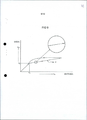
[00046] Conforme ilustrado na Figura 9, quando o pedal de freio 41 é também manipulado, a pressão Pm do óleo de funcionamento na câmara de cilindro 82 e a câmara de cilindro de regulagem de pressão 86 é gradualmente aumentada. Quando a pressão Pm chega a uma pressão de ponto de freio Pc, a pressão do óleo de funcionamento que age no pistão de válvula 89 (na direção para baixo) excede uma força de mola da mola de compressão 88 e, assim, o pistão de válvula 89 é movido na direção para baixo (vide Figura 8(b)). Devido ao movimento do pistão de válvula 89 a base de válvula 90a é levado em contato com uma superfície superior da base de válvula 96, a câmara de cilindro de regulagem de pressão 86 e a câmara de válvula 93 são interrompidas uma da outra e, portanto, a pressão (pressão de saída) do orifício de suprimento de pressão de óleo 64 (câmara de válvula 93) se torna a pressão do ponto de freio Pc. Além disso, uma fórmula de equilíbrio quando o pistão de válvula 89 inicia o movimento é expressa por uma fórmula que se segue (fórmula 2), e a pressão de ponto de freio Pc é expressa por uma fórmula que se segue (fórmula 3). Fórmula 2 Pm=W/B Fórmula 3 Pc=(W+LxK)/B[00046] As illustrated in Figure 9, when the
[00047] Quando a pressão Pm do óleo de funcionamento na câmara de cilindro de regulagem de pressão 86 é adicionalmente aumentada a partir de tal estado, o pistão de válvula 89 é ligeiramente impulsionado para cima e é aberto e, portanto, a pressão na câmara de válvula 93 (o orifício de suprimento de pressão de óleo 64) é aumentada. Assim, o pistão de válvula 89 é novamente impulsionado para baixo de maneira que a base de válvula 90a e a superfície superior da base de válvula 96 sejam levadas em contato uma com a outra por meio do que a câmara de cilindro de regulagem de pressão 86 e a câmara de válvula 93 são interrompidas uma da outra. A operação acima mencionada é repetidamente realizada e, portanto, conforme ilustrado em uma vista parcialmente ampliada que é circundada por um círculo na Figura 9, a pressão na câmara de válvula 93 (o orifício de pressão de óleo 64) é reduzido quando comparada com a pressão de entrada e aumentada em uma maneira em degraus por minuto. Então, a pressão reduzida do orifício de pressão de óleo 64 é expressa por uma fórmula que se segue (fórmula 4). Assim, uma proporção de redução de pressão tanθ(Pw/Pm) nesse ponto do tempo é expressa por uma fórmula que se segue (fórmula 5). Conforme pode ser compreendido da fórmula (fórmula 5), a redução de pressão tanθ é determinada com base na área de sessão transversal A do elemento de válvula 90 e a área de sessão transversal B da parte de diâmetro pequeno 92. O ajuste apropriado de ambas as áreas A, B é possível para obter a redução de pressão arbitrária tanθ. Fórmula 4 Pw=(A-B)/AxPm+(W+LxK)/A Fórmula 5 tanθ=(A-B)/A=1-B/A[00047] When the pressure Pm of the operating oil in the pressure regulating
[00048] A seguir, quando o pedal de freio 41 é liberado, o pistão 70 é movido para baixo dentro da câmara de cilindro 82 devido a uma força de mola da mola de retorno 85 de maneira que a pressão Pm do óleo de funcionamento dentro da câmara de pressão de óleo 84 e da câmara de cilindro de regulagem de pressão 86 seja diminuída. Assim, devido à relação entre a área de recebimento de pressão do elemento de válvula 90 do pistão de válvula 89 e a área de recebimento de pressão da parte de diâmetro pequeno 92, o pistão de válvula é movido para baixo contra uma força de mola da mola de compressão 89 e, portanto, a vedação de válvula 96 é deformada, por meio disso um volume da câmara de válvula 93 é alterado diminuindo, portanto, a pressão na câmara de válvula 93. Além disso, quando a pressão Pm na câmara de cilindro de regulagem de pressão 86 é diminuída, o pistão de válvula 89 é impulsionado para cima devido à ação da mola de compressão 88 e retorna para uma posição original de maneira que a câmara de válvula 93 e a câmara de cilindro de regulagem de pressão 86 se comuniquem uma com a outra por meio disso a pressão Pw na câmara de válvula 93 é diminuída para a mesma pressão.[00048] Next, when the
[00049] Controlando a frenagem da motocicleta 10 usando o regulador de pressão 62 conforme descrito acima, é possível conferir a característica de freio desejada à roda dianteira FW e à roda de freio traseira RW.[00049] By controlling the braking of motorcycle 10 using
[00050] A seguir, serão explicadas em detalhe a constituição e a maneira de operação do mecanismo de freio dianteiro 110 que aplica a força de frenagem à roda dianteira FW, em combinação com as Figuras de 10 a 12.[00050] In the following, the constitution and operation of the
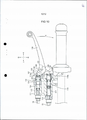
[00051] O mecanismo de freio dianteiro 110 está, conforme ilustrado da Figura 10 a Figura 12, disposto em uma parte lateral direita da alavanca 21. Em um corpo de cilindro 111 fixado na alavanca 21, estão formadas uma câmara de cilindro mestre secundária 112 e uma câmara de cilindro mestre dianteira 113 paralelas uma a outra. A câmara de cilindro mestre secundária 112 está conectada com uma mangueira elástica dianteira 74 de uma rota de freio de intertravamento 55 e se comunica com o orifício de suprimento de pressão de óleo 65 do regulador de pressão 62. Além disso, um calibrador de freio dianteiro 53a está conectado à câmara de cilindro mestre dianteira 113 por meio da mangueira de freio 75.[00051] The
[00052] Um pistão secundário 114 que é polarizado na direção em que o pistão secundário 114 é impulsionado dentro da câmara de cilindro mestre secundária 112 devido à mola de compressão 115 estar fixada deslizantemente na câmara de cilindro mestre secundária 112, e uma parte de extremidade 114a do pistão secundário 114 está configurada para se projetar ou retrair no corpo de cilindro 111.[00052] A secondary piston 114 which is polarized in the direction in which the secondary piston 114 is propelled into the secondary master cylinder chamber 112 due to the
[00053] Na câmara de cilindro mestre dianteira 113, um pistão dianteiro 116 que é polarizado na direção em que o pistão dianteiro 116 é impulsionado para fora da câmara de cilindro mestre dianteira 113 devido à mola de compressão 117 é fixado deslizantemente. Uma parte de extremidade 116a do pistão dianteiro 116 está configurada para se projetar do ou se retrair para o corpo de cilindro 111. Além disso, uma parte de extremidade 114a do pistão secundário 114 e uma parte de extremidade 116a do pistão dianteiro 116 estão dispostas fora do corpo de cilindro 111 na direção da largura do veículo. Ademais, no corpo de cilindro 111, é formado um ladrão 131 para descarregar ar na câmara de cilindro mestre secundária 112 e na câmara de cilindro mestre dianteira 113, e o ladrão 131 é coberto com uma tampa de ladrão 132.[00053] In the front master cylinder chamber 113, a
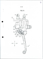
[00054] Conforme ilustrado na Figura 10, em uma parte de extremidade direita do corpo de cilindro 111, está montado um eixo de suporte 118 entre a câmara de cilindro mestre secundária 112 e a câmara de cilindro mestre dianteira 113. Uma parte de extremidade proximal 120 de uma alavanca de freio 119 para aplicar uma força de frenagem à roda dianteira FW está sustentada oscilantemente no eixo de suporte 118. Além disso, uma parte em degraus 121 sendo dotada de uma forma aproximadamente em L conforme vista em uma vista plana é formada em uma superfície inferior da parte de extremidade proximal 120 da alavanca de freio 119.[00054] As shown in Figure 10, on a right end part of
[00055] Ademais, uma argola dupla 122 sendo dotada de uma forma aproximadamente triangular é sustentada oscilantemente no eixo de suporte 118, e a argola dupla 122 é encaixada na parte em degraus 121 da alavanca de freio 119 de maneira sobreposta. A argola dupla 122 é formada de um membro de chapa sendo dotado de uma forma aproximadamente triangular, e inclui uma primeira parte de impulsão 123 formada em uma posição correspondendo a uma parte de extremidade 114a do pistão secundário 114, e uma segunda parte de impulsão 124 formada em uma posição correspondendo a uma parte de extremidade 116a do pistão dianteiro 116, e uma parte de engate de intertravamento 125 formada em uma posição correspondendo à parte em degraus 121 da alavanca de freio 119.[00055] In addition, a
[00056] Além disso, uma mola de compressão 126 é incorporada entre a parte em degrau 121 da alavanca de freio 119 e a parte de engate de intertravamento 125 da argola dupla 122. A mola de compressão 126 é proporcionada para polarizar a alavanca de freio 119 e a argola dupla 122 de maneira que a alavanca de freio 119 e a argola dupla 122 sejam giradas nas direções opostas uma a outra absorvendo, portanto, um movimento na direção rotacional entre a alavanca de freio 119 e a argola dupla 122. Quando a alavanca de freio 119 é girada na direção indicada por uma seta X ao ser manipulada, a parte em degrau 121 da alavanca de freio 119 é levada em contato com a parte de engate de intertravamento 125 da argola dupla 122, de maneira que a argola dupla 122 também seja girada na direção indicada pela seta X.[00056] In addition, a
[00057] Além disso, conforme ilustrado na Figura 11 e na Figura 12, uma parte de impulsão de interruptor 127 é formada na argola dupla 122 em uma maneira se projetando para baixo. A parte de impulsão de interruptor 127 está configurada para sempre impulsionar uma alavanca de interruptor 129 de um interruptor de lâmpada de freio 128 fixada em uma parte inferior do corpo do cilindro 111. Quando a argola dupla 122 é girada na direção indicada pela seta X, é liberado um estado impulsionado da alavanca de interruptor 129 pela parte de impulsão de interruptor 127. Desta maneira, interruptor de lâmpada de freio 128 apaga a lâmpada de freio 40 em um estado de não manipulação de freio (estado de impulsão) e acende a lâmpada de freio 40 em um estado de manipulação de freio (estado de não impulsão).[00057] In addition, as shown in Figure 11 and Figure 12, a
[00058] A seguir, será explicada a maneira de operação do dispositivo de freio de intertravamento 50 dessa modalidade.[00058] Next, the operation of the interlocking
[00059] Primeiro, é explicado o caso em que o freio é aplicado à roda dianteira FW devido à manipulação da alavanca de freio 119. Conforme ilustrado na Figura 10, quando o motociclista manipula giratoriamente a alavanca de freio 119 na direção indicada pela seta X, a parte em degraus 121 da alavanca de freio 119 é engatada com a parte de engate de intertravamento 125 da argola dupla 122 de maneira que a argola dupla 122 seja girada na direção indicada pela seta X. Dessa maneira, a segunda parte de impulsão 124 da argola dupla 122 impulsiona uma parte de extremidade 116a do pistão dianteiro 116 e impulsiona o pistão dianteiro 116 para dentro de uma câmara de cilindro mestre dianteiro 113 contra a força de mola da mola de compressão e, portanto, é aumentada a pressão do óleo de funcionamento na câmara de cilindro mestre dianteiro 113.[00059] First, the case where the brake is applied to the front wheel FW due to the manipulation of the
[00060] Então, o óleo de funcionamento na câmara de cilindro mestre dianteiro 113 é suprido para o calibrador de freio dianteiro 53a por meio de uma mangueira de freio 75 de maneira a suprir uma força de frenagem para a roda dianteira FW. Além disso, quando a argola dupla 122 é girada, a alavanca de interruptor 129 do interruptor da lâmpada de freio 128 que é impulsionada pela parte de impulsão de interruptor 127 é liberado e, portanto, a lâmpada de freio 40 é ligada.[00060] Then, the operating oil in the front master cylinder chamber 113 is supplied to the
[00061] A seguir, é explicado o caso no qual o freio é aplicado à roda dianteira FW e a roda traseira RW devido à manipulação do pedal de freio 41. Conforme ilustrado nas Figuras 7 e 10, quando o motociclista manipula giratoriamente o pedal de freio 41 com seu pé, essa rotação impulsiona o pistão 70 para dentro da câmara de cilindro 82 contra a força de mola da mola de retorno 85 por meio do esteio de ligação 68 e a haste de conexão 69. Assim, é aumentada a pressão Pm do óleo de funcionamento na câmara de pressão 84 e a câmara de cilindro de regulagem de pressão 86.[00061] The following explains the case in which the brake is applied to the front wheel FW and the rear wheel RW due to the manipulation of the
[00062] Uma parte do óleo de funcionamento na câmara de cilindro de regulagem de pressão 86 é suprida para a câmara de cilindro mestre 112 a partir do orifício de pressão de óleo 65 por meio da rota de freio de intertravamento 55 de maneira a mover o pistão secundário 114 na direção lateral direita do corpo do veículo contra a força de polarização da mola de compressão 115. Assim, uma parte de extremidade 114a do pistão secundário 114 se projeta a partir do corpo de cilindro 111 e impulsiona a primeira parte de impulso 123 da argola dupla 122 e, portanto, a argola dupla 122 é girada na direção indicada pela seta X em volta do eixo de suporte 118. Assim, a segunda parte de impulso 124 impulsiona uma parte de extremidade 116a do pistão dianteiro 116 de maneira a mover o pistão dianteiro 116 na direção lateral esquerda do corpo do veículo aumentando, portanto, a pressão do óleo de funcionamento na câmara de cilindro mestre dianteira 113. Então, o óleo de funcionamento é suprido para o calibrador de freio dianteiro 53a de maneira a aplicar a força de frenagem para a roda dianteira FW.[00062] A portion of the operating oil in the pressure regulating
[00063] Uma vez que o orifício de suprimento de pressão de óleo 65 e a câmara de cilindro de regulagem de pressão 86 se comunicam um com o outro, a pressão substancialmente igual à pressão na câmara de cilindro de regulagem de pressão 86 gerada pela manipulação do pedal de freio 41 é aplicada ao pistão secundário 114 da câmara de cilindro mestre secundária 112. Contudo, o pistão secundário 114 é polarizado na direção contra a pressão do óleo de funcionamento suprido da câmara de cilindro de regulagem de pressão 86 devido à mola de compressão 115 e, portanto, o pistão secundário 114 não é movido até que a pressão do óleo de funcionamento suprida do orifício de suprimento de pressão de óleo 65 seja aumentada para uma pressão predeterminada que supera a força de mola da mola de compressão 115. Em outras palavras, não é aplicada nenhuma força de frenagem para o freio dianteiro 53 até que a pressão do óleo de funcionamento suprida do orifício de suprimento de pressão de óleo 65 seja aumentada para uma pressão predeterminada que possa superar a força de mola da mola de compressão 115.[00063] Since the oil
[00064] Além disso, quando a argola dupla 122 é girada pelo pistão secundário 114, apenas a argola dupla 122 é girada e a alavanca de freio 119 não é girada. Contudo, a mola de compressão 126 está montada entre a alavanca de freio 119 e a argola dupla 122 de maneira a polarizar a alavanca de freio 119 na direção oposta à direção indicada pela seta X e, portanto, pode ser absorvido um movimento da alavanca de freio na direção rotacional.[00064] Furthermore, when the
[00065] Além disso, outra parte do óleo de funcionamento na câmara de cilindro de regulagem de pressão 86 é dotada de uma pressão da mesma regulada na maneira acima mencionada pelo pistão de válvula 89 e a vedação de válvula 96 e, portanto, o óleo de funcionamento de pressão regulada é suprido para o calibrador de freio traseiro 52a do freio traseiro 52 por meio da câmara de válvula 93, para o orifício de suprimento de pressão de óleo 64 e para a rota de freio traseiro 54 de maneira a aplicar uma força de frenagem à roda traseira RW.[00065] In addition, another part of the operating oil in the pressure regulating
[00066] Conforme explicado acima, de acordo com o dispositivo de freio de intertravamento 50 da motocicleta 10 dessa modalidade, o cilindro mestre posterior 61 para suprir pressão de óleo correspondente à manipulação de freio de um motociclista para o freio traseiro 52 e o regulador de pressão 62 para regular a pressão de óleo do cilindro mestre traseiro 61 e para suprir pressão de óleo para o freio dianteiro hidráulico 53 são integralmente montados no dispositivo de freio de intertravamento, e o regulador de pressão 62 está disposto dentro do cilindro mestre traseiro 61 na direção da largura do veículo e acima da área de oscilação H do braço de oscilação 24 que sustenta oscilante e articuladamente a roda traseira RW do veículo 10 e, portanto, é possível encurtar uma extensão do cilindro mestre do tipo integral regulador de pressão 51 que é integralmente formado do cilindro mestre traseiro 61 e do regulador de pressão 62 e, ao mesmo tempo, é possível facilmente montar o cilindro mestre do tipo integral regulador de pressão 51 no corpo do veículo em uma maneira compacta ao mesmo tempo em que assegura um intervalo entre o cilindro mestre do tipo integral regulador de pressão 51 e o braço de oscilação 24. Ademais, ajustando a pressão do óleo de funcionamento usando o regulador de pressão 62, é possível conferir uma força de frenagem sendo dotada da característica de frenagem desejada para a roda dianteira FW e para a roda traseira RW.[00066] As explained above, according to the interlocking
[00067] Além disso, de acordo com o dispositivo de freio de intertravamento 50 da motocicleta 10 dessa modalidade, a armação do corpo de veículo 11 do veículo 10 inclui o membro de retenção de estribo de assento traseiro 18, e o cilindro mestre do tipo integral regulador de pressão 51 está montado no membro de retenção de estribo de assento traseiro 18 e, portanto, é possível facilmente montar o cilindro mestre do tipo integral regulador de pressão 51 no corpo do veículo de maneira compacta ao mesmo tempo em que evita seguramente a interferência do cilindro mestre 51 com o braço de oscilação 24 que oscila juntamente com o funcionamento do veículo 10.[00067] In addition, according to the interlocking
[00068] Além disso, de acordo com o dispositivo de freio de intertravamento 50 da motocicleta 10 dessa modalidade, o dispositivo de freio de intertravamento 50 inclui a rota de freio traseiro 54 que conecta o regulador de pressão 62 e o freio traseiro 52 e a rota de freio de intertravamento 56 que conecta o regulador de pressão 62 e o freio dianteiro 53, e os orifícios de suprimento de pressão de óleo 64, 65 para conectar a rota de freio 54 e a rota de freio de intertravamento 55 ao regulador de pressão 62 são respectivamente formados no regulador de pressão em um estado que os orifícios de suprimento de pressão de óleo 64, 65 são direcionados para dentro da motocicleta 10 na direção da largura do veículo e, portanto, é possível encurtar as extensões das respectivas rotas de freio 54, 55, a partir do regulador de pressão 62 para o freio dianteiro 53 e o freio traseiro 52 respectivamente. Ademais, a disposição das respectivas rotas de freio 54, 55 pode ser facilmente realizada ao mesmo tempo em que asseguram um intervalo entre as rotas de freio 54, 55 e os componentes periféricos e, portando, é possível realçar a aparência da motocicleta 10.[00068] In addition, according to the motorcycle
[00069] Além disso, de acordo com o dispositivo de freio de intertravamento 50 da motocicleta 10 dessa modalidade, a rota de freio de intertravamento 55 inclui a mangueira elástica traseira 72 conectada ao regulador 62, o tubo intermediário feito de metal 73 conectado à mangueira elástica traseira 72 e a mangueira elástica dianteira 74 conectada ao tubo intermediário 73, e a parte de conexão 76 entre o tubo intermediário 73 e a mangueira elástica dianteira 74 está disposta na frente do tubo frontal 13 da motocicleta 10 e na proximidade do centro na direção da largura do veículo e, portanto, é possível dispor a rota de freio de intertravamento 55 ao mesmo tempo em que assegura um intervalo entre um grupo de mangueiras da rota de freio de intertravamento 55 e os componentes periféricos como, por exemplo, um luz farol dianteiro 39 no momento de direção de uma alavanca. Além disso, o tubo intermediário feito de metal 73 está disposto entre a mangueira elástica traseira 72 e a mangueira elástica dianteira 74 e, portanto, é possível obter a alta rigidez de freio.[00069] Furthermore, according to the interlocking
[00070] A Figura 1 é uma vista lateral de uma motocicleta na qual está montado um dispositivo de freio de intertravamento de uma motocicleta de acordo com a presente invenção.[00070] Figure 1 is a side view of a motorcycle on which a motorcycle interlocking brake device according to the present invention is mounted.
[00071] A Figura 2 é uma vista lateral para explicar toda a constituição do dispositivo de freio de intertravamento.[00071] Figure 2 is a side view to explain the entire constitution of the interlocking brake device.
[00072] A Figura 3 é uma vista para explicar toda a constituição do dispositivo de freio de intertravamento.[00072] Figure 3 is a view to explain the entire constitution of the interlocking brake device.
[00073] A Figura 4 é uma vista ampliada de uma parte essencial para explicar uma posição de disposição de um cilindro mestre do tipo integral regulador de pressão.[00073] Figure 4 is an enlarged view of an essential part to explain a disposition position of a master cylinder of the integral pressure regulator type.
[00074] A figura 5 é uma vista em perspectiva do cilindro mestre do tipo integral regulador de pressão montado no retentor de estribo de assento traseiro conforme visto de uma lateral esquerda e dianteira do corpo de veículo.[00074] Figure 5 is a perspective view of the master cylinder of the integral pressure regulator type mounted on the rear seat stirrup retainer as seen from the left and front side of the vehicle body.
[00075] A Figura 6 é uma vista plana do cilindro mestre do tipo integral regulador de pressão ilustrado na Figura 5 conforme visto de cima.[00075] Figure 6 is a plan view of the master cylinder of the integral pressure regulator type illustrated in Figure 5 as seen from above.
[00076] A Figura 7 é uma vista em corte transversal tomada ao longo da linha A-A na Figura 4.[00076] Figure 7 is a cross-sectional view taken along line A-A in Figure 4.
[00077] A Figura 8 é uma vista em corte transversal ampliada de uma parte essencial para explicar uma operação do cilindro mestre do tipo integral regulador de pressão.[00077] Figure 8 is an enlarged cross-sectional view of an essential part to explain a master cylinder operation of the integral pressure regulator type.
[00078] A Figura 9 é um gráfico ilustrando uma curva característica de um regulador de pressão.[00078] Figure 9 is a graph illustrating a characteristic curve of a pressure regulator.
[00079] A Figura 10 é uma vista plana de uma parte interrompida longe de um mecanismo de freio dianteiro montado em uma alavanca conforme vista de cima.[00079] Figure 10 is a plan view of an interrupted part away from a front brake mechanism mounted on a lever as seen from above.
[00080] A Figura 11 é uma vista traseira com uma parte interrompida longe do mecanismo de freio dianteiro ilustrado na Figura 10 conforme visto de baixo.[00080] Figure 11 is a rear view with a broken part away from the front brake mechanism shown in Figure 10 as seen from below.
[00081] A Figura 12 é uma vista frontal do mecanismo de freio dianteiro ilustrado na Figura 10 conforme visto de uma face dianteira. Descrição das Referências Numéricas e dos sinais 10: motocicleta 11: armação de corpo de veículo 12: garfo dianteiro 13: tubo frontal 14: armação principal 15: chapa de pivô 16: armação traseira 17: armação de reforço 18: membro de retenção de estribo de assento traseiro 21: alavanca 24: braço de oscilação 39: farol dianteiro 40: lâmpada de freio 41: pedal de freio 50: dispositivo de freio de intertravamento 51: cilindro mestre do tipo integral regulador de pressão 52: freio traseiro 53: freio dianteiro 54: rota de freio traseiro 55: rota de freio de intertravamento 61: cilindro mestre traseiro 62: regulador de pressão 64: orifício de suprimento de pressão de óleo 65: orifício de suprimento de pressão de óleo 72: mangueira elástica traseira 73: tubo intermediário 74: mangueira elástica dianteira 76: parte de conexão 110: mecanismo de freio dianteiro 111: corpo de cilindro 112: câmara de cilindro mestre secundária 113: câmara de cilindro mestre dianteira 114: pistão secundário 115: mola de compressão 116: pistão dianteiro 117: mola de compressão 118: eixo de suporte 119: alavanca de freio 122: argola dupla FW: roda dianteira RW: roda traseira H: variação oscilante do braço oscilante[00081] Figure 12 is a front view of the front brake mechanism illustrated in Figure 10 as seen from a front face. Description of Numerical References and signs 10: motorcycle 11: vehicle body frame 12: front fork 13: front tube 14: main frame 15: pivot plate 16: rear frame 17: reinforcement frame 18: stirrup retaining member rear seat 21: lever 24: swing arm 39: headlight 40: brake lamp 41: brake pedal 50: interlock brake device 51: master cylinder of integral pressure regulator type 52: rear brake 53: front brake 54: rear brake route 55: interlocking brake route 61: rear master cylinder 62: pressure regulator 64: oil pressure supply port 65: oil pressure supply port 72: rear elastic hose 73: intermediate pipe 74: front elastic hose 76: connection part 110: front brake mechanism 111: cylinder body 112: secondary master cylinder chamber 113: front master cylinder chamber 114: secondary piston 115: spring compression wheel 116: front piston 117: compression spring 118: support shaft 119: brake lever 122: double ring FW: front wheel RW: rear wheel H: swing arm swing
Claims (4)
Applications Claiming Priority (2)
| Application Number | Priority Date | Filing Date | Title |
|---|---|---|---|
| JP2007-235462 | 2007-09-11 | ||
| JP2007235462A JP4883414B2 (en) | 2007-09-11 | 2007-09-11 | Interlocking brake device for motorcycles |
Publications (3)
| Publication Number | Publication Date |
|---|---|
| BRPI0803577A2 BRPI0803577A2 (en) | 2009-05-05 |
| BRPI0803577B1 true BRPI0803577B1 (en) | 2021-04-13 |
| BRPI0803577B8 BRPI0803577B8 (en) | 2022-09-06 |
Family
ID=40603876
Family Applications (1)
| Application Number | Title | Priority Date | Filing Date |
|---|---|---|---|
| BRPI0803577A BRPI0803577B8 (en) | 2007-09-11 | 2008-09-09 | MOTORCYCLE INTERLOCK BRAKE DEVICE |
Country Status (4)
| Country | Link |
|---|---|
| JP (1) | JP4883414B2 (en) |
| CN (1) | CN101423098B (en) |
| BR (1) | BRPI0803577B8 (en) |
| MY (1) | MY180563A (en) |
Families Citing this family (8)
| Publication number | Priority date | Publication date | Assignee | Title |
|---|---|---|---|---|
| JP5593274B2 (en) * | 2011-06-29 | 2014-09-17 | 本田技研工業株式会社 | Saddle riding |
| JP5953100B2 (en) * | 2012-04-26 | 2016-07-20 | 本田技研工業株式会社 | Step part structure of saddle-ride type vehicle |
| JP6041305B2 (en) * | 2012-08-24 | 2016-12-07 | 曙ブレーキ工業株式会社 | Front / rear interlocking brake mechanism |
| CN104815868A (en) * | 2015-04-22 | 2015-08-05 | 贵州大学 | Machining process of high-strength and heat-resisting aluminum alloy wires |
| EP3409571B1 (en) | 2016-01-28 | 2020-01-22 | Yamaha Hatsudoki Kabushiki Kaisha | Saddled vehicle equipped with combined brake system |
| TWI636915B (en) * | 2016-06-21 | 2018-10-01 | 液壓系統發展股份有限公司 | Brake master cylinder device and vehicle provided with the brake master cylinder device |
| CN106627947B (en) * | 2017-02-13 | 2022-10-28 | 江门市大长江集团有限公司 | Riding type motorcycle linkage brake device and riding type motorcycle |
| JP6773704B2 (en) * | 2018-03-15 | 2020-10-21 | 本田技研工業株式会社 | Rear brake hose layout structure for saddle-riding vehicles |
Family Cites Families (6)
| Publication number | Priority date | Publication date | Assignee | Title |
|---|---|---|---|---|
| JPS55102759A (en) * | 1979-01-30 | 1980-08-06 | Sumitomo Electric Ind Ltd | Master cylinder for autobicycle |
| JPS5747282A (en) * | 1980-09-04 | 1982-03-18 | Yamaha Motor Co Ltd | Front and rear interlocking brake for autobicycle |
| JP3270194B2 (en) * | 1993-05-10 | 2002-04-02 | 本田技研工業株式会社 | Interlocking brake device for vehicles |
| JP4153174B2 (en) * | 2001-03-28 | 2008-09-17 | 本田技研工業株式会社 | Motorcycle front cowl structure |
| JP4306442B2 (en) * | 2003-12-19 | 2009-08-05 | スズキ株式会社 | Motorcycle with anti-lock brake device |
| JP4326506B2 (en) * | 2005-07-01 | 2009-09-09 | 川崎重工業株式会社 | Motorcycle |
-
2007
- 2007-09-11 JP JP2007235462A patent/JP4883414B2/en not_active Expired - Fee Related
-
2008
- 2008-08-27 CN CN2008101463749A patent/CN101423098B/en not_active Expired - Fee Related
- 2008-09-05 MY MYPI20083434A patent/MY180563A/en unknown
- 2008-09-09 BR BRPI0803577A patent/BRPI0803577B8/en not_active IP Right Cessation
Also Published As
| Publication number | Publication date |
|---|---|
| MY180563A (en) | 2020-12-02 |
| JP2009067133A (en) | 2009-04-02 |
| CN101423098A (en) | 2009-05-06 |
| JP4883414B2 (en) | 2012-02-22 |
| BRPI0803577B8 (en) | 2022-09-06 |
| BRPI0803577A2 (en) | 2009-05-05 |
| CN101423098B (en) | 2011-10-12 |
Similar Documents
| Publication | Publication Date | Title |
|---|---|---|
| BRPI0803577B1 (en) | MOTORCYCLE INTERLOCK BRAKE DEVICE | |
| JP6660964B2 (en) | bicycle | |
| ES2311139T3 (en) | CONTROL UNIT OF HYDRAULIC BRAKES OF BICYCLES, MOTORCYCLES AND SIMILAR VEHICLES. | |
| TWI558606B (en) | Bicycle hydraulic component operating device | |
| JP6577053B2 (en) | Hydraulic brake system, bicycle, and control method of hydraulic brake system | |
| TWI788391B (en) | Hydraulic operating device | |
| BR102013024188B1 (en) | MOTORCYCLE BRAKE DEVICE | |
| TWI906221B (en) | Hydraulic operating device for human-powered vehicle | |
| BRPI1100683B1 (en) | combined brake system for motorcycle | |
| BR102012029935B1 (en) | brake tube structure of a motorcycle | |
| BR102013024666A2 (en) | combined brake system for a saddle mount type vehicle | |
| TW201910178A (en) | Operating device | |
| JP2009179260A (en) | Interlocking brake device for motorcycles | |
| BR112012017323B1 (en) | motorcycle brake device | |
| CN109305279B (en) | Hydraulic operating system | |
| BRPI0902834A2 (en) | vehicle engine unit and mounting vehicle | |
| TW201803765A (en) | Hydraulic time difference brake device (2) | |
| TW202110694A (en) | Operating device for human-powered vehicle | |
| TW202308890A (en) | Hydraulic operating device for human-powered vehicle | |
| BR102013026402A2 (en) | MOTORCYCLE | |
| JP2009269418A (en) | Air supply device for tire of two-wheeler | |
| BRPI1105916A2 (en) | SLAVE CYLINDER AND VEHICLE OF TYPE EQUIPPED WITH THE SAME | |
| JP2016141182A (en) | Saddle-riding type vehicle | |
| TW202308891A (en) | Hydraulic operating device for human-powered vehicle | |
| TWI307667B (en) | Interlocking brake system for bar-handle vehicle |
Legal Events
| Date | Code | Title | Description |
|---|---|---|---|
| B03A | Publication of a patent application or of a certificate of addition of invention [chapter 3.1 patent gazette] | ||
| B06F | Objections, documents and/or translations needed after an examination request according [chapter 6.6 patent gazette] | ||
| B06U | Preliminary requirement: requests with searches performed by other patent offices: procedure suspended [chapter 6.21 patent gazette] | ||
| B06A | Patent application procedure suspended [chapter 6.1 patent gazette] | ||
| B06A | Patent application procedure suspended [chapter 6.1 patent gazette] | ||
| B09A | Decision: intention to grant [chapter 9.1 patent gazette] | ||
| B16A | Patent or certificate of addition of invention granted [chapter 16.1 patent gazette] |
Free format text: PRAZO DE VALIDADE: 10 (DEZ) ANOS CONTADOS A PARTIR DE 13/04/2021, OBSERVADAS AS CONDICOES LEGAIS. |
|
| B16C | Correction of notification of the grant [chapter 16.3 patent gazette] |
Free format text: REF. RPI 2623 DE 13/04/2021 QUANTO AO TITULAR. |
|
| B21F | Lapse acc. art. 78, item iv - on non-payment of the annual fees in time |
Free format text: REFERENTE A 15A ANUIDADE. |
|
| B24J | Lapse because of non-payment of annual fees (definitively: art 78 iv lpi, resolution 113/2013 art. 12) |
Free format text: EM VIRTUDE DA EXTINCAO PUBLICADA NA RPI 2739 DE 04-07-2023 E CONSIDERANDO AUSENCIA DE MANIFESTACAO DENTRO DOS PRAZOS LEGAIS, INFORMO QUE CABE SER MANTIDA A EXTINCAO DA PATENTE E SEUS CERTIFICADOS, CONFORME O DISPOSTO NO ARTIGO 12, DA RESOLUCAO 113/2013. |