BRPI0905189B1 - impact tool - Google Patents
impact tool Download PDFInfo
- Publication number
- BRPI0905189B1 BRPI0905189B1 BRPI0905189-9A BRPI0905189A BRPI0905189B1 BR PI0905189 B1 BRPI0905189 B1 BR PI0905189B1 BR PI0905189 A BRPI0905189 A BR PI0905189A BR PI0905189 B1 BRPI0905189 B1 BR PI0905189B1
- Authority
- BR
- Brazil
- Prior art keywords
- tool
- impact
- bit
- drill
- tool holder
- Prior art date
Links
- 238000006073 displacement reaction Methods 0.000 claims abstract description 14
- 238000009527 percussion Methods 0.000 claims description 16
- 230000033001 locomotion Effects 0.000 claims description 14
- 230000005540 biological transmission Effects 0.000 claims description 3
- 238000006243 chemical reaction Methods 0.000 description 13
- 239000002184 metal Substances 0.000 description 12
- 230000014759 maintenance of location Effects 0.000 description 9
- 238000010276 construction Methods 0.000 description 6
- 238000000034 method Methods 0.000 description 4
- 230000002411 adverse Effects 0.000 description 1
- 238000005553 drilling Methods 0.000 description 1
- 238000004519 manufacturing process Methods 0.000 description 1
- 238000003825 pressing Methods 0.000 description 1
Images


Classifications
-
- B—PERFORMING OPERATIONS; TRANSPORTING
- B25—HAND TOOLS; PORTABLE POWER-DRIVEN TOOLS; MANIPULATORS
- B25D—PERCUSSIVE TOOLS
- B25D17/00—Details of, or accessories for, portable power-driven percussive tools
- B25D17/11—Arrangements of noise-damping means
-
- B—PERFORMING OPERATIONS; TRANSPORTING
- B25—HAND TOOLS; PORTABLE POWER-DRIVEN TOOLS; MANIPULATORS
- B25D—PERCUSSIVE TOOLS
- B25D17/00—Details of, or accessories for, portable power-driven percussive tools
- B25D17/08—Means for retaining and guiding the tool bit, e.g. chucks allowing axial oscillation of the tool bit
-
- B—PERFORMING OPERATIONS; TRANSPORTING
- B25—HAND TOOLS; PORTABLE POWER-DRIVEN TOOLS; MANIPULATORS
- B25D—PERCUSSIVE TOOLS
- B25D17/00—Details of, or accessories for, portable power-driven percussive tools
- B25D17/24—Damping the reaction force
-
- B—PERFORMING OPERATIONS; TRANSPORTING
- B25—HAND TOOLS; PORTABLE POWER-DRIVEN TOOLS; MANIPULATORS
- B25D—PERCUSSIVE TOOLS
- B25D2211/00—Details of portable percussive tools with electromotor or other motor drive
- B25D2211/003—Crossed drill and motor spindles
-
- B—PERFORMING OPERATIONS; TRANSPORTING
- B25—HAND TOOLS; PORTABLE POWER-DRIVEN TOOLS; MANIPULATORS
- B25D—PERCUSSIVE TOOLS
- B25D2217/00—Details of, or accessories for, portable power-driven percussive tools
- B25D2217/0011—Details of anvils, guide-sleeves or pistons
- B25D2217/0019—Guide-sleeves
-
- B—PERFORMING OPERATIONS; TRANSPORTING
- B25—HAND TOOLS; PORTABLE POWER-DRIVEN TOOLS; MANIPULATORS
- B25D—PERCUSSIVE TOOLS
- B25D2222/00—Materials of the tool or the workpiece
- B25D2222/54—Plastics
- B25D2222/57—Elastomers, e.g. rubber
-
- B—PERFORMING OPERATIONS; TRANSPORTING
- B25—HAND TOOLS; PORTABLE POWER-DRIVEN TOOLS; MANIPULATORS
- B25D—PERCUSSIVE TOOLS
- B25D2250/00—General details of portable percussive tools; Components used in portable percussive tools
- B25D2250/345—Use of o-rings
Landscapes
- Engineering & Computer Science (AREA)
- Mechanical Engineering (AREA)
- Percussive Tools And Related Accessories (AREA)
Abstract
FERRAMENTA DE IMPACTO. Um objetivo da invenção consiste em reduzir o ruido causado pelo deslocamento de uma broca de ferramenta em uma ferramenta de impacto. A ferramenta de impacto representativa de acordo com a invenção inclui um suporte de ferramenta 137 que aloja uma broca de ferramenta 119, de tal maneira que a broca de ferramenta possa se movimentar linearmente em sua direção axial, e um barril 108 que é integralmente conectado ao suporte de ferramenta 137. A ferramenta de impacto inclui adicionalmente um elemento elástico 155 que é disposto entre uma superfície circunferencial interna do suporte de ferramenta 137 e uma superfície circunferencial externa da broca de ferramenta 119 em uma região de extremidade da broca de ferramenta 119 no lado do barril e conectado intimamente ao suporte de ferramenta 137 e à broca de ferramenta 119 ao longo de um comprimento pré-determinado da broca de ferramenta 119 na direção axial. O elemento elástico 155 aplica uma força de inclinação para evitar um deslocamento da broca de ferramenta 119 em uma direção transversal à direção axial. Adicionalmente, um elemento intermediário 145 entra em contato de ponto com a broca de ferramenta 119 em sua linha central axial. Desenhos Representativos: Figura 1IMPACT TOOL. An objective of the invention is to reduce the noise caused by the displacement of a tool bit in an impact tool. The representative impact tool according to the invention includes a tool holder 137 that houses a tool bit 119, such that the tool bit can move linearly in its axial direction, and a barrel 108 that is integrally connected to the tool holder 137. The impact tool additionally includes an elastic element 155 which is disposed between an internal circumferential surface of the tool holder 137 and an external circumferential surface of the tool drill 119 in an end region of the tool drill 119 on the side of the barrel and intimately connected to the tool holder 137 and the tool drill 119 over a predetermined length of the tool drill 119 in the axial direction. The elastic element 155 applies a tilting force to prevent displacement of the tool drill 119 in a direction transverse to the axial direction. In addition, an intermediate element 145 comes into contact with the tool drill 119 in its axial center line. Representative Drawings: Figure 1
Description
[001] A invenção refere-se a uma ferramenta de impacto.[001] The invention relates to an impact tool.
[002] WO 2007/000899 A1 divulga um perfurador e US 4476941 A descreve outra ferramenta de percussão.[002] WO 2007/000899 A1 discloses a perforator and US 4476941 A describes another percussion tool.
[003] A publicação de patente japonesa no 2646108 revela uma ferramenta de impacto que executa uma operação de martelamento em uma peça de trabalho tal como concreto. Quando a broca de ferramenta é acionada e a operação de martelamento é executada, a broca de ferramenta recebe uma força de reação da peça de trabalho.[003] Japanese patent publication 2646108 reveals an impact tool that performs a hammering operation on a workpiece such as concrete. When the tool bit is engaged and the hammering operation is carried out, the tool bit receives a reaction force from the workpiece.
[004] Em muitos casos, a força de reação inclui não somente componentes axiais, mas também componentes radiais, de modo que a broca de ferramenta se submete a um deslocamento em uma direção radial. Tal deslocamento radial é causado não somente na broca de ferramenta, mas também em um elemento intermediário tal como um parafuso de impacto, pois o parafuso de impacto está em contato com a broca de ferramenta. Quando a broca de ferramenta e o parafuso de impacto se submetem ao deslocamento radial e golpeiam um suporte de ferramenta para retê-lo, um som de metal contra metal causado por tal golpeamento gera ruído para o exterior através do suporte de ferramenta e do barril conectado ao suporte de ferramenta.[004] In many cases, the reaction force includes not only axial components, but also radial components, so that the tool bit undergoes a displacement in a radial direction. Such radial displacement is caused not only in the tool bit, but also in an intermediate element such as an impact screw, as the impact screw is in contact with the tool bit. When the tool bit and the impact screw undergo radial displacement and strike a tool holder to retain it, a metal-to-metal sound caused by such a strike generates noise to the outside through the tool holder and the connected barrel to the tool holder.
[005] Assim sendo, um objetivo da invenção consiste em reduzir efetivamente o ruído que é causado pelo deslocamento de uma broca de ferramenta em uma ferramenta de impacto.[005] Therefore, an objective of the invention is to effectively reduce the noise that is caused by the displacement of a tool drill in an impact tool.
[006] Um objetivo descrito acima pode ser alcançado por uma ferramenta de impacto de acordo com a reivindicação 1. A ferramenta de impacto representativa de acordo com a invenção inclui um suporte de ferramenta que aloja a broca de ferramenta e um barril integralmente conectado ao suporte de ferramenta. A ferramenta de impacto inclui ainda um elemento de percussão alojado no interior do barril para executar um movimento linear e um elemento intermediário também alojado no interior do barril para ser acionado pelo elemento de percussão para se mover linearmente na direção axial para o contato com a broca de ferramenta, transmitindo assim uma força de acionamento para a broca de ferramenta. O elemento intermediário entra em contato de ponto com a broca de ferramenta em sua linha central axial. Ao menos o elemento intermediário ou a broca de ferramenta pode ser formado com uma superfície esférica a fim de fornecer o contato de ponto.[006] An objective described above can be achieved by an impact tool according to claim 1. The representative impact tool according to the invention includes a tool holder that houses the tool bit and a barrel integrally connected to the holder of tool. The impact tool also includes a percussion element housed inside the barrel to perform a linear movement and an intermediate element also housed inside the barrel to be driven by the percussion element to move linearly in the axial direction for contact with the drill. tool, thus transmitting a driving force to the tool bit. The intermediate element comes into contact with the tool bit on its axial center line. At least the intermediate element or tool bit can be formed with a spherical surface in order to provide point contact.
[007] A ferramenta de impacto inclui adicionalmente um elemento elástico que é disposto entre uma superfície circunferencial interna do suporte de ferramenta e uma superfície circunferencial externa da broca de ferramenta em uma região de extremidade da broca de ferramenta no lado do barril e conectada intimamente ao suporte de ferramenta e a broca de ferramenta por um comprimento pré-determinado da broca de ferramenta na direção axial. Com esta construção, o elemento elástico aplica uma força de inclinação para evitar um deslocamento da broca de ferramenta em uma direção transversal à direção axial.[007] The impact tool additionally includes an elastic element that is disposed between an inner circumferential surface of the tool holder and an outer circumferential surface of the tool bit in an end region of the tool bit on the side of the barrel and intimately connected to the tool holder and tool bit for a predetermined length of the tool bit in the axial direction. With this construction, the elastic element applies a tilt force to prevent the tool bit from shifting in a direction transverse to the axial direction.
[008] Adicionalmente,, quando a broca de ferramenta se submete ao deslocamento em uma direção transversal à direção axial pela força de reação aplicada a partir da peça de trabalho para a broca de ferramenta durante uma operação da ferramenta de impacto, o elemento elástico disposto entre a broca de ferramenta e o suporte de ferramenta aplica uma força de inclinação para evitar o deslocamento da broca de ferramenta. Como um resultado, o deslocamento da broca de ferramenta pode ser minimizado de modo que o golpeamento da broca de ferramenta contra o suporte de ferramenta pode ser evitado ou reduzido. Adicionalmente, devido ao fato de que o elemento intermediário entra em contato de ponto com a broca de ferramenta, evita-se que o movimento da broca de ferramenta em qualquer direção além da direção axial seja transmitido para o elemento intermediário. Dessa forma, o deslocamento do elemento intermediário pode ser aliviado. Desta maneira, o ruído causado pelo deslocamento da broca de ferramenta pode ser efetivamente reduzido.[008] Additionally, when the tool bit is displaced in a direction transversal to the axial direction by the reaction force applied from the workpiece to the tool bit during an impact tool operation, the elastic element disposed between the tool bit and the tool holder apply a tilt force to prevent the tool bit from moving. As a result, displacement of the tool bit can be minimized so that striking the tool bit against the tool holder can be avoided or reduced. Additionally, due to the fact that the intermediate element comes into contact with the tool bit, the movement of the tool bit in any direction other than the axial direction is prevented from being transmitted to the intermediate element. In this way, the displacement of the intermediate element can be relieved. In this way, the noise caused by the displacement of the tool bit can be effectively reduced.
[009] Adicionalmente, o elemento elástico pode ser conectado intimamente à broca de ferramenta somente parcialmente em uma direção circunferencial da broca de ferramenta. Para este recurso, o elemento elástico pode ser conformado como um anel que é contínuo na direção circunferencial, e uma superfície da parede externa do anel pode ser conformada de modo que o anel seja mantido em contato com a broca de ferramenta em uma pluralidade de pontos em sua direção circunferencial. Alternativamente, o elemento elástico pode ser formado por uma pluralidade de elementos elásticos separados entre si na direção circunferencial.[009] Additionally, the elastic element can be intimately connected to the tool bit only partially in a circumferential direction of the tool bit. For this feature, the elastic element can be shaped like a ring that is continuous in the circumferential direction, and a surface of the outer wall of the ring can be shaped so that the ring is kept in contact with the tool bit at a plurality of points in its circumferential direction. Alternatively, the elastic element can be formed by a plurality of elastic elements separated from each other in the circumferential direction.
[0010] Em uma ferramenta de impacto tal como um martelete elétrico e uma furadeira de impacto, a broca de ferramenta pode ser mantida de tal maneira que seja linearmente móvel através da inserção de uma haste da broca de ferramenta em um orifício de retenção de broca do suporte de ferramenta na direção longitudinal. Adicionalmente, o elemento elástico é mantido em contato com a broca de ferramenta somente parcialmente em sua direção circunferencial. Portanto, quando a broca de ferramenta é inserida no orifício de retenção de broca do suporte de ferramenta a fim de fixar a broca de ferramenta ao suporte de ferramenta, o elemento elástico pode ser mais facilmente deformado de modo que a broca de ferramenta possa ser mais facilmente inserida no orifício de retenção de broca do suporte de ferramenta.[0010] In an impact tool such as an electric hammer and an impact drill, the tool bit can be maintained in such a way that it is linearly movable by inserting a tool bit shank into a bit holding hole of the tool holder in the longitudinal direction. In addition, the elastic element is kept in contact with the tool bit only partially in its circumferential direction. Therefore, when the tool bit is inserted into the tool holder bit retention hole in order to secure the tool bit to the tool holder, the elastic element can be more easily deformed so that the tool bit can be more easily inserted into the drill holder hole of the tool holder.
[0011] Adicionalmente, o elemento elástico pode ter um formato similar a anel e a broca de ferramenta ou o elemento elástico pode ter uma seção circular e o outro pode ter uma seção poligonal.[0011] Additionally, the elastic element may have a ring-like shape and the tool drill or elastic element may have a circular section and the other may have a polygonal section.
[0012] Adicionalmente, ao menos parte do elemento intermediário pode ser disposta no interior do suporte de ferramenta, uma luva pode ser disposta entre o elemento intermediário e o suporte de ferramenta, e um membro elástico pode ser disposto entre a luva e o suporte de ferramenta.[0012] Additionally, at least part of the intermediate element can be arranged inside the tool holder, a glove can be arranged between the intermediate element and the tool holder, and an elastic member can be arranged between the sleeve and the tool holder tool.
[0013] Adicionalmente, o elemento intermediário pode entrar em contato de ponto com o elemento de percussão em sua linha central longitudinal. Outros objetivos, recursos e vantagens da presente invenção serão prontamente entendidos após a leitura da seguinte descrição detalhada junto com os desenhos e as reivindicações em anexo.[0013] Additionally, the intermediate element can come into contact with the percussion element in its longitudinal center line. Other objectives, resources and advantages of the present invention will be readily understood after reading the following detailed description together with the attached drawings and claims.
[0014] A Figura 1 é uma vista lateral seccional que mostra um martelete elétrico integral 101 de acordo com uma modalidade representativa da invenção.[0014] Figure 1 is a sectional side view showing an integral
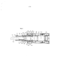
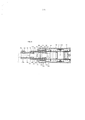
[0015] A Figura 2 é uma vista seccional ampliada de uma parte (em um lado da broca da furadeira de impacto) da Figura 1, sob condições não carregadas nas quais a broca da furadeira de impacto 119 não é pressionada contra uma peça de trabalho.[0015] Figure 2 is an enlarged sectional view of part (on one side of the impact drill bit) of Figure 1, under unloaded conditions in which the
[0016] A Figura 3 é uma vista seccional ampliada da parte (no lado da broca da furadeira de impacto) da Figura 1, sob condições carregadas nas quais a broca da furadeira de impacto 119 é pressionada contra uma peça de trabalho.[0016] Figure 3 is an enlarged sectional view of the part (on the impact drill bit side) of Figure 1, under loaded conditions in which the
[0017] A Figura 4 é uma vista seccional que mostra uma estrutura de encaixe de um anel de borracha 155 em uma porção de diâmetro pequeno 119c da broca da furadeira de impacto 119.[0017] Figure 4 is a sectional view showing a fitting structure of a
[0018] A Figura 5 é uma vista seccional que mostra uma variante da estrutura de encaixe do anel de borracha 155 na porção de diâmetro pequeno 119c da broca da furadeira de impacto 119.[0018] Figure 5 is a sectional view showing a variant of the fitting structure of the
[0019] Cada uma das etapas de método e recursos adicionais reveladas acima e abaixo pode ser utilizada separadamente ou em conjunto com outras etapas de método e recursos para fornecer e fabricar ferramentas de impacto aprimoradas e método para uso de tais ferramentas de impacto e dispositivos utilizados no mesmo. Os exemplos representativos da presente invenção, cujos exemplos utilizaram muitas destas etapas de método e recursos adicionais em conjunto, serão descritos agora em detalhes com referência aos desenhos. Esta descrição detalhada é meramente destinada a ensinar detalhes adicionais para um versado na técnica para praticar os aspectos preferenciais dos presentes ensinamentos e não se destina a limitar o escopo da invenção. Somente as reivindicações definem o escopo da invenção reivindicada. Portanto, as combinações de recursos e etapas reveladas na seguinte descrição detalhada podem não ser necessárias para a prática da invenção em seu sentido mais amplo e, adversamente, são ensinadas simplesmente para descreverem particularmente alguns exemplos representativos da invenção, cuja descrição detalhada será dada no momento com referência aos desenhos em anexo.[0019] Each of the additional method steps and resources revealed above and below can be used separately or in conjunction with other method steps and resources to provide and manufacture improved impact tools and method for using such impact tools and devices used. the same. Representative examples of the present invention, examples of which used many of these additional method steps and resources together, will now be described in detail with reference to the drawings. This detailed description is merely intended to teach additional details for one skilled in the art to practice the preferred aspects of the present teachings and is not intended to limit the scope of the invention. Only the claims define the scope of the claimed invention. Therefore, the combinations of features and steps revealed in the following detailed description may not be necessary for the practice of the invention in its broadest sense and, adversely, are taught simply to describe particularly some representative examples of the invention, the detailed description of which will be given in the moment with reference to the attached drawings.
[0020] Uma modalidade representativa da invenção é descrita agora com referência às Figuras de 1 a 5. A Figura 1 mostra um martelete elétrico integral 101 como uma modalidade representativa de uma ferramenta de impacto de acordo com a invenção. As Figuras 2 e 3 são vistas parcialmente ampliadas do martelete elétrico 101 na Figura 1, sob condições não carregadas nas quais uma broca da furadeira de impacto 119 não é pressionada contra uma peça de trabalho e sob condições carregadas nas quais a broca da furadeira de impacto 119 é pressionada contra a peça de trabalho, respectivamente. A Figura 4 mostra uma estrutura de encaixe de um anel de borracha 155 em uma porção de diâmetro pequeno 119c da broca da furadeira de impacto 119, e a Figura 5 mostra uma variante da estrutura de encaixe do anel de borracha 155 na porção de diâmetro pequeno 119c da broca da furadeira de impacto 119.[0020] A representative embodiment of the invention is now described with reference to Figures 1 to 5. Figure 1 shows an integral
[0021] Conforme mostrado na Figura 1, o martelete elétrico 101 de acordo com esta modalidade representativa inclui principalmente um corpo de ferramenta na forma de um corpo 103 que forma uma carcaça externa do martelete elétrico 101, um suporte de ferramenta 137 conectado a uma região de extremidade apical (no lado esquerdo quando visualizado na Figura 1) do corpo 103 em sua direção longitudinal, uma broca da furadeira de impacto 119 montada de modo separável ao suporte de ferramenta 137 e uma pega manual 109 que é conectada à outra extremidade (no lado direito quando visualizado na Figura 1) do corpo 103 em sua direção longitudinal e projetada para ser segurada por um usuário. A broca da furadeira de impacto 119 é um recurso que corresponde a uma "broca de ferramenta" de acordo com a invenção. A broca da furadeira de impacto 119 é presa pelo suporte de ferramenta 137 de tal modo que seja permitida a alternância em relação ao suporte de ferramenta em sua direção axial (a direção longitudinal do corpo 103) e evitada a rotação em relação ao suporte de ferramenta em sua direção circunferencial. A guisa de conveniência na explicação, em uma posição horizontal do corpo 103 na qual uma direção axial da broca da furadeira de impacto 119 coincide com uma direção horizontal, o lado da broca da furadeira de impacto 119 é adotado como a frente, e o lado da pega manual 109 como a traseira.[0021] As shown in Figure 1,
[0022] O corpo 103 inclui principalmente um alojamento de motor 105 que aloja um motor de acionamento 111, um alojamento de engrenagem 107 que é conectado ao alojamento de motor 105 e aloja um mecanismo de conversão de movimentação 113 e um mecanismo de redução de velocidade de engrenagem 117 e um barril tubular 108 que é conectado ao alojamento de engrenagem 107 e aloja um mecanismo de percussão 115. O alojamento de engrenagem 107 é disposto em uma região na frente e acima do alojamento de motor 105. O barril 108 é disposto em uma extremidade frontal do alojamento de engrenagem 107 e se estende para frente em um eixo geométrico da broca da furadeira de impacto 119. Adicionalmente, uma pega manual 109 é conectada à traseira do alojamento de motor 105 e forma uma empunhadura em formato de D. Uma chave elétrica 131 que energiza o motor de acionamento 111 e um membro operacional 133 que é operado para mover a chave elétrica 131 entre uma posição de liga e uma posição de desliga são dispostos em uma região superior da pega manual 109. O membro operacional 133 é montado na pega manual 109 de tal modo que possa deslizar em uma direção horizontal (direção transversal) transversal à direção axial da broca da furadeira de impacto. Quando o usuário desliza o membro operacional 133 pelo dedo a fim de mover a chave elétrica 133 para a posição de liga, o motor de acionamento 111 é energizado.[0022]
[0023] Uma saída rotatória do motor de acionamento 111 é apropriadamente convertida em movimentação linear pelo mecanismo de conversão de movimentação 113 e, então, transmitida para o mecanismo de percussão 115. Como um resultado, uma força de impacto é gerada na direção axial da broca da furadeira de impacto 119 através do mecanismo de percussão 115. O motor de acionamento 111 é disposto de tal modo que um eixo geométrico do eixo de saída 112 se estenda em uma direção transversal para o eixo geométrico da broca da furadeira de impacto 119. O mecanismo de conversão de movimentação 113 é alojado em uma região superior de um espaço interno do alojamento de engrenagem 107 e serve para converter a saída rotatória do motor de acionamento 111 em movimentação linear e transmiti-la ao mecanismo de percussão 115.[0023] A rotary output of
[0024] O mecanismo de conversão de movimentação 113 que serve para converter a rotação do motor de acionamento 111 em movimentação linear e transmiti-la para o mecanismo de percussão 115, inclui principalmente um mecanismo de manivela. O mecanismo de manivela é projetado de tal modo que, quando o mecanismo de manivela é acionado rotatoriamente pelo motor de acionamento 111, um pistão 129 que forma um membro móvel final do mecanismo de manivela se move linearmente na direção axial da broca da furadeira de impacto no interior de um cilindro 141. O pistão 129 é um recurso que corresponde ao "elemento de acionamento" de acordo com a invenção. O mecanismo de manivela é disposto na frente do motor de acionamento 111 e acionado pelo motor de acionamento 111 em velocidade reduzida através do mecanismo de redução de velocidade de engrenagem 117 que é formado por uma pluralidade de engrenagens. As construções do mecanismo de conversão de movimentação 113 e do mecanismo de redução de velocidade de engrenagem 117 são bem conhecidas e, portanto, sua explicação detalhada é omitida.[0024] The
[0025] O mecanismo de percussão 115 inclui principalmente um elemento de percussão na forma de um percussor 143 que é disposto de modo deslizável no interior de um furo do cilindro 141 junto com o pistão 129, e um parafuso de impacto 145 que é disposto de modo deslizável no interior do suporte de ferramenta 137. O percussor 143 é acionado através de uma ação elástica de ar ou variações de pressão de uma câmara de ar 141a do cilindro 141 que é ocasionado pelo movimento deslizante do pistão 129 e, então, o percussor 143 colide com o parafuso de impacto 145 e transmite a força de percussão para a broca da furadeira de impacto 119 através do parafuso de impacto 145. O percussor 143 e o parafuso de impacto 145 são recursos que correspondem ao "elemento de percussão"e o "elemento intermediário", respectivamente, de acordo com a invenção.[0025] The
[0026] Conforme mostrado nas Figuras 2 e 3, o parafuso de impacto 145 é configurado como um membro colunar escalonado que tem uma porção de diâmetro grande 145a, uma porção de diâmetro pequeno 145b e uma porção escalonada radial 145c formada em uma região limítrofe entre a porção de diâmetro pequeno e grande 145a, 145b, na direção axial do parafuso de impacto 145. Adicionalmente, o parafuso de impacto 145 é disposto no interior do suporte de ferramenta 137 com a porção de diâmetro grande 145a na frente e a porção de diâmetro pequeno 145b na traseira.[0026] As shown in Figures 2 and 3, the
[0027] O martelete elétrico 101 trem um membro de posicionamento 121. Quando um usuário aplica força de pressionamento dianteira ao corpo 103 e, dessa forma, a broca da furadeira de impacto 119 é pressionada contra uma peça de trabalho, que é definida as condições carregadas conforme mostrado na Figura 3, o parafuso de impacto 145 é impulsionado para trás para o lado do pistão 129 junto com a broca da furadeira de impacto 119. Neste estado, o membro de posicionamento 121 entra em contato com a porção escalonada 145c do parafuso de impacto 145 e assim posiciona o corpo 103 em relação à peça de trabalho. O membro de posicionamento 121 é configurado como uma parte unitária que inclui um anel de borracha 123, uma arruela metálica frontal rígida 125 que é conectada a uma superfície frontal axial do anel de borracha 123 e pode ser mantida em contato com a porção escalonada 145c do parafuso de impacto 145, e uma arruela metálica traseira rígida 127 que é conectada a uma superfície traseira axial do anel de borracha 123 e mantida em contato com a superfície da extremidade frontal do cilindro 141. O membro de posicionamento 121 pode ser encaixado livremente sobre a porção de diâmetro pequeno 145b do parafuso de impacto 145. Adicionalmente, é evitado o movimento para trás do cilindro 141 na direção axial pelo alojamento de engrenagem 107 (vide Figura 1).[0027] The
[0028] O suporte de ferramenta 137 é conectado de modo separável à região de extremidade apical do barril 108 por roscas 151. O suporte de ferramenta 137 é configurado como membro de retenção de broca e tem um orifício de retenção de broca 137a com uma seção hexagonal através da qual a broca da furadeira de impacto 119 é inserida. A broca da furadeira de impacto 119 tem uma haste poligonal 119a com uma seção hexagonal no meio em sua direção axial, e a haste poligonal 119a é inserida e encaixada no orifício de retenção de broca 137a, de tal modo que a broca da furadeira de impacto 119 é impedida de girar em relação ao suporte de ferramenta 137.[0028]
[0029] Um entalhe plano 119b é formado em uma parte circunferencial da haste poligonal 119a da broca da furadeira de impacto 119 e se estende por um comprimento pré-determinado na direção axial. Um retentor de ferramenta 153 é fornecido no suporte de ferramenta 137 e serve para evitar que a broca da furadeira de impacto 119 inserida no orifício de retenção de broca 137a deslize para fora. O retentor de ferramenta 153 é um membro de pino em formato similar a bastão que tem uma seção circular e é disposto transversalmente na direção axial da broca da furadeira de impacto 119. Adicionalmente, o retentor de ferramenta 153 é engatado a uma porção de extremidade traseira do entalhe 119b da broca da furadeira de impacto 119 e evita assim que a broca da furadeira de impacto 119 deslize para fora. Neste estado, permite-se o movimento da broca da furadeira de impacto 119 em relação ao suporte de ferramenta 137 na direção axial em uma faixa do comprimento do entalhe 119b. Adicionalmente, um entalhe plano, que não é mostrado, é formado em uma parte circunferencial do retentor de ferramenta 153 e se estende por um comprimento pré-determinado em sua direção longitudinal. Quando o retentor de ferramenta 153 é girado em torno de seu eixo geométrico para uma posição na qual o entalhe do retentor de ferramenta 153 está oposto ao entalhe 119b da broca da furadeira de impacto 119, o retentor de ferramenta 153 é desengatado do entalhe 119b, de tal modo que seja permitido que a broca da furadeira de impacto 119 seja removida do orifício de retenção de broca 137a.[0029] A
[0030] Um furo 137b que tem uma seção circular e um diâmetro maior que o do orifício de retenção de broca 137a é formado em uma região de extremidade traseira do suporte de ferramenta 137. Uma porção de diâmetro pequeno 119c que tem uma seção circular e um diâmetro menor que o da haste poligonal 119a é formada na porção de extremidade traseira da broca da furadeira de impacto 119. Em um estado no qual a broca da furadeira de impacto 119 é inserida no orifício de retenção de broca 137a e impedida de deslizar (conforme mostrado na Figura 2), a porção de diâmetro pequeno 119c é localizada no interior do furo 137b. Um anel de borracha 155 que tem um orifício de anel de uma seção poligonal é encaixado no furo 137b em contato próximo com a superfície de parede do furo. Portanto, quando a broca da furadeira de impacto 119 é inserida no orifício de retenção de broca 137a, o anel de borracha 155 prende elasticamente a porção de diâmetro pequeno 119c inserida no orifício do anel de borracha 155.[0030] A hole 137b that has a circular section and a larger diameter than the
[0031] Especificamente, o anel de borracha 155 é disposto entre a superfície de parede do furo 137b e a porção de diâmetro pequeno 119c sobre a porção de extremidade traseira da broca da furadeira de impacto 119, e mantida em contato próximo com a superfície de parede do furo 137b e a superfície circunferencial externa da porção de diâmetro pequeno 119c sobre um comprimento pré-determinado da broca da furadeira de impacto 119 em sua direção axial. Portanto, quando a broca da furadeira de impacto 119 se move linearmente em sua direção axial, o anel de borracha 155 exerce uma força de inclinação sobre a broca da furadeira de impacto 119 em direções que minimizem o deslocamento da broca da furadeira de impacto 119 em uma direção (doravante chamada de direção radial) transversal a sua direção axial. O anel de borracha 155 é um recurso que corresponde ao "elemento elástico"de acordo com a invenção.[0031] Specifically, the
[0032] Adicionalmente, conforme mostrado na Figura 4, o orifício de anel do anel de borracha 155 tem um formato hexagonal e a porção de diâmetro pequeno 119c da broca da furadeira de impacto 119 tem uma seção circular. Com esta construção, o anel de borracha 155 mantém a porção de diâmetro pequeno 119c em contato em seis pontos na direção circunferencial. Portanto, quando a broca da furadeira de impacto 119 é inserida no orifício de retenção de broca 137a a fim de ser montado no suporte de ferramenta 137, a porção de diâmetro pequeno 119c é mantida em contato com o orifício de anel superfície de parede do anel de borracha 155 parcialmente na direção circunferencial e, neste estado, a porção de diâmetro pequeno 119c é inserida no orifício de anel do anel de borracha 155. Neste instante, comparado com uma construção, por exemplo, no qual a porção de diâmetro pequeno é mantida em contato com o orifício de anel superfície de parede em sua totalidade na direção circunferencial, o anel de borracha 155 pode ser mais facilmente deformado, de modo que a broca da furadeira de impacto 119 possa ser mais facilmente inserida no orifício de retenção de broca 137a.[0032] Additionally, as shown in Figure 4, the ring bore of the
[0033] A superfície frontal do anel de borracha 155 é mantida em contato com uma superfície de extremidade 137c que é radialmente formada em uma porção escalonada entre o furo 137b e o orifício de retenção de broca 137a, de modo que o anel de borracha 155 seja impedido de se movimentar adicionalmente para frente. Adicionalmente, uma luva 157 é disposta na traseira do anel de borracha 155 (no lado do percussor 143). A luva 157 serve como um membro para impedir que o anel de borracha 155 se movimente para trás. Uma extremidade traseira axial da luva 157 é mantida em contato com a arruela metálica frontal 125 do membro de posicionamento 121 e sua extremidade frontal axial é mantida em contato com uma superfície traseira do anel de borracha 155 através de uma arruela metálica 161. Com esta construção, o anel de borracha 155 é disposto no interior do furo 137b do suporte de ferramenta 137 no estado no qual é impedido de se movimentar na direção axial. Adicionalmente, a arruela metálica 161 é encaixada livremente sobre a porção de diâmetro pequeno 119c da broca da furadeira de impacto 119.[0033] The front surface of the
[0034] Adicionalmente, a luva 157 também serve como um membro para guiar um movimento linear do parafuso de impacto 145. A luva 157 é coaxialmente disposta no interior do furo 137b do suporte de ferramenta 137 e o parafuso de impacto 145 é encaixado de modo deslizável no furo. Um diâmetro externo da luva 157 é menor que um diâmetro do furo 137b do suporte de ferramenta 137, de tal modo que uma folga pré-determinada seja definida entre a superfície circunferencial externa da luva e a superfície de parede do furo. Adicionalmente, uma pluralidade de (três nesta modalidade representativa) anéis em O 159 é encaixada na luva 157 em intervalos pré-determinados na direção axial, e a luva 157 é conectada ao suporte de ferramenta 137 através dos anéis em O 159. Com esta construção, os anéis em O 159 servem para evitar ou reduzir a transmissão de vibração do parafuso de impacto 145 para o suporte de ferramenta 137 através da luva 157. O anel em O 159 é um recurso que corresponde ao "membro elástico"de acordo com a invenção.[0034] Additionally,
[0035] Adicionalmente, uma superfície da extremidade frontal 145d e uma superfície de extremidade traseira do parafuso de impacto 145 na direção axial são dimensionada esfericamente de tal modo que um impacto da broca da furadeira de impacto 119 para o parafuso de impacto 145 e um impacto do parafuso de impacto 145 para o percussor 143 sejam transmitidos na direção axial. Uma superfície de extremidade traseira da broca da furadeira de impacto 119 e uma superfície da extremidade frontal do percussor 143 compreendem uma superfície plana perpendicular à direção axial. Portanto, o parafuso de impacto 145 entra em contato esférico com a superfície de extremidade traseira da broca da furadeira de impacto 119 e a superfície da extremidade frontal do percussor 143. Especificamente, o parafuso de impacto 145 entra em contato de ponto com a broca da furadeira de impacto 119 e o percussor 143 em sua linha central axial. A superfície de extremidade traseira da broca da furadeira de impacto 119 e a superfície da extremidade frontal do percussor 143 também podem ser dimensionadas esfericamente. Adicionalmente, todos dentre a broca da furadeira de impacto 119, o suporte de ferramenta 137, o barril 108, a luva 157, o parafuso de impacto 145 e o percussor 143 são feitos de metal.[0035] Additionally, a front end surface 145d and a rear end surface of the
[0036] No martelete elétrico 101 construído conforme descrito acima, quando o motor de acionamento 111 é acionado, o pistão 129 do mecanismo de manivela se move linearmente no interior do cilindro 141, que faz com que o percussor 143 seja acionado através da ação elástica do ar da câmara de ar 141a. Então, o percussor 143 aplica uma força de percussão na direção axial à broca da furadeira de impacto 119 através do parafuso de impacto 145. Deste modo, a broca da furadeira de impacto 119 é ocasionada a se mover linearmente na direção axial e executa uma operação de martelamento sobre a peça de trabalho.[0036] In the
[0037] Durante a operação de martelamento descrita acima, uma força de reação é aplicada a partir da peça de trabalho para a broca da furadeira de impacto 119 após o movimento de percussão. Esta força de reação pode incluir não somente componentes axiais, mas também componentes radiais, de tal modo que a broca da furadeira de impacto 119 possa se mover linearmente enquanto é submetida ao deslocamento em uma direção transversal para a direção axial.[0037] During the hammering operation described above, a reaction force is applied from the workpiece to the drill of the
[0038] Consequentemente, nesta modalidade representativa, o anel de borracha 155 encaixado no furo 137b do suporte de ferramenta 137 mantém a porção de diâmetro pequeno 119c da broca da furadeira de impacto 119 na região de extremidade traseira da broca da furadeira de impacto 119 e aplica uma força de inclinação nas direções que evitam ou minimizam o deslocamento radial da broca da furadeira de impacto 119. Portanto, mesmo se a força de reação que tem não somente componentes axiais, mas também componentes radiais aplicados a partir da peça de trabalho para a broca da furadeira de impacto 119, o deslocamento radial da broca da furadeira deimpacto 119 pode ser evitado ou minimizado. Dessa forma, o golpeamento da broca da furadeira de impacto 119 contra o suporte de ferramenta 137 pode ser evitado ou reduzido. Como um resultado, o ruído (som de metal contra metal que é causado por uma colisão entre a broca da furadeira de impacto 119 e o suporte de ferramenta 137) que é liberado para o exterior através do suporte de ferramenta 137 e do barril 108 conectado ao suporte de ferramenta 137 pode ser reduzido.[0038] Consequently, in this representative embodiment, the
[0039] Adicionalmente, nesta modalidade representativa, o parafuso de impacto 145 é projetado para entrar em contato com a superfície de extremidade traseira da broca da furadeira de impacto 119 através de sua superfície esférica. Portanto, mesmo se a broca da furadeira de impacto 119 entrar em contato com o parafuso de impacto 145 enquanto se submete ao deslocamento radial, o impacto que é causado pela força de reação da broca da furadeira de impacto 119 é aplicado ao parafuso de impacto 145 na direção axial. Especificamente, mesmo se a broca da furadeira de impacto 119 se mover linearmente enquanto é submetida ao deslocamento na direção radial, o movimento da broca da furadeira de impacto 119 em qualquer direção diferente da direção axial é impedido de ser transmitido para o parafuso de impacto 145. Dessa forma, o deslocamento do parafuso de impacto 145 pode ser evitado ou atenuado.[0039] Additionally, in this representative embodiment, the
[0040] Adicionalmente, nesta modalidade representativa, a luva 157 é disposta entre o parafuso de impacto 145 e o suporte de ferramenta 137, e os anéis em O 159 são dispostos entre a periferia externa da luva 157 e a superfície de parede do furo 137b do suporte de ferramenta 137. Portanto, a transmissão de vibração do parafuso de impacto 145 para o suporte de ferramenta 137 através da luva 157 pode ser evitado ou reduzido pelos anéis em O 159. Como um resultado, o ruído que é liberado para o exterior através do suporte de ferramenta 137 e do barril 108 conectado ao suporte de ferramenta 137pode ser reduzido adicionalmente.[0040] Additionally, in this representative embodiment,
[0041] Adicionalmente, como para a estrutura de encaixe do anel de borracha 155 na porção de diâmetro pequeno 119c da broca da furadeira de impacto 119, o orifício de anel do anel de borracha 155 tem um formato hexagonal e a porção de diâmetro pequeno 119c tem um formato circular. Entretanto, conforme mostrado na Figura 5, isto pode ser de outro modo ou, especificamente, o orifício de anel do anel de borracha 155 pode ter um formato circular e a porção de diâmetro pequeno 119c pode ter um formato hexagonal. Adicionalmente, qualquer formato poligonal além do formato hexagonal pode ser usado. Adicionalmente, a fim de mantida em contato com a porção de diâmetro pequeno 119c da broca da furadeira de impacto 119 em uma pluralidade de pontos na direção circunferencial, o anel de borracha 155 pode ser configurado para ter uma superfície da parede externa com projeções e depressões que se estendem axialmente que são alternadamente dispostas na direção circunferencial. Adicionalmente, como o elemento elástico, uma pluralidade de elementos elásticos que são separados entre si na direção circunferencial pode ser usada em vez do anel de borracha 155.[0041] Additionally, as for the rubber
[0042] Adicionalmente, uma mola metálica também pode ser usada como o elemento elástico no lugar do anel de borracha 155. A mola metálica pode ser fornecida, por exemplo, de tal modo que uma pluralidade de molas lamelares que se estendem axialmente são separadas entre si na direção circunferencial ou de tal modo que um elemento tubular seja formado como sua base e uma pluralidade de peças de mola que se estendem axialmente que são cortadas e elevadas radialmente para dentro do elemento tubular são dispostas na direção circunferencial. Adicionalmente, nesta modalidade representativa, o elemento elástico é formado pelo anel de borracha 155 e configurado para ser mantido em contato com a porção de diâmetro pequeno 119c da broca da furadeira de impacto 119 em uma pluralidade de pontos na direção circunferencial, mas pode ser configurada para ser mantido em contato em sua totalidade na direção circunferencial.[0042] In addition, a metal spring can also be used as the elastic element in place of the
[0043] Adicionalmente, nesta modalidade representativa, a superfície da extremidade frontal 145d e a superfície de extremidade traseira 145e do parafuso de impacto 145 são dimensionadas esfericamente de tal modo que um impacto da broca da furadeira de impacto 119 para o parafuso de impacto 145 e um impacto do parafuso de impacto 145 para o percussor 143 sejam transmitidos na direção axial. Entretanto, além disso, a superfície de extremidade traseira da broca da furadeira de impacto 119 e a superfície da extremidade frontal do percussor 143 também podem ser dimensionadas esfericamente. Alternativamente, a superfície da extremidade frontal 145d e a superfície de extremidade traseira 145e do parafuso de impacto 145 podem compreender uma superfície plana perpendicular à direção axial, enquanto a superfície de extremidade traseira da broca da furadeira de impacto 119 e a superfície da extremidade frontal do percussor 143 podem compreender uma superfície esférica.[0043] Additionally, in this representative embodiment, the front end surface 145d and the
[0044] Adicionalmente, na modalidade representativa descrita acima, o martelete elétrico 101 é explicado como um exemplo representativo da ferramenta de impacto. Entretanto, esta modalidade representativa não se limita ao martelete elétrico e também pode ser aplicada a uma furadeira de impacto que pode acionar a broca da furadeira de impacto para executar um movimento de martelamento na direção axial e um movimento de perfuração na direção circunferencial.[0044] Additionally, in the representative modality described above, the
[0045] Adicionalmente, em relação aos aspectos descritos acima, os seguintes recursos podem ser fornecidos:[0045] Additionally, in relation to the aspects described above, the following resources can be provided:
[0046] "Quando o lado da broca da furadeira de impacto é definido como a frente e o lado do mecanismo de acionamento como a traseira, o movimento frontal do anel de borracha disposto no interior do suporte de ferramenta é evitado por uma superfície de parede que é radialmente formada no suporte de ferramenta, e adicionalmente impedido de se movimentar para trás por uma luva que é disposta no interior do suporte de ferramenta e impedida de se mover para trás".[0046] "When the drill bit of the impact drill is defined as the front and the drive mechanism side as the rear, the frontal movement of the rubber ring disposed inside the tool holder is prevented by a wall surface which is radially formed in the tool holder, and additionally prevented from moving backwards by a glove that is arranged inside the tool holder and prevented from moving backwards ".
[0047] "Uma arruela similar a anel pode ser disposta entre o anel de borracha e a luva". Descrição dos Numerais 101 martelete elétrico (ferramenta de impacto) 103 corpo (corpo de ferramenta) 105 alojamento de motor 107 alojamento de engrenagem 108 barril 109 pega manual 111 motor de acionamento 112 eixo de saída 113 mecanismo de conversão de movimentação 115 mecanismo de percussão 117 mecanismo de redução de velocidade de engrenagem 119 broca da furadeira de impacto (broca de ferramenta) 119a haste poligonal 119b entalhe 119c porção de diâmetro pequeno 121 membro de posicionamento 123 anel de borracha 125 arruela metálica frontal 127 arruela metálica traseira 129 pistão 131 chave elétrica 133 membro operacional 137 suporte de ferramenta 137a orifício de retenção de broca 137b furo 137c superfície de extremidade 141 cilindro 141a câmara de ar 143 percussor (elemento de percussão) 145 parafuso de impacto (elemento intermediário) 145d superfície da extremidade frontal 145e superfície de extremidade traseira 151 rosca 153 retentor de ferramenta 155 anel de borracha (elemento elástico) 157 luva 159 anel em O (membro elástico)[0047] "A ring-like washer can be arranged between the rubber ring and the sleeve". Description of
Claims (6)
Applications Claiming Priority (2)
| Application Number | Priority Date | Filing Date | Title |
|---|---|---|---|
| JP2008-324775 | 2008-12-19 | ||
| JP2008324775A JP5294826B2 (en) | 2008-12-19 | 2008-12-19 | Impact tool |
Publications (2)
| Publication Number | Publication Date |
|---|---|
| BRPI0905189A2 BRPI0905189A2 (en) | 2011-02-15 |
| BRPI0905189B1 true BRPI0905189B1 (en) | 2021-03-09 |
Family
ID=41739315
Family Applications (1)
| Application Number | Title | Priority Date | Filing Date |
|---|---|---|---|
| BRPI0905189-9A BRPI0905189B1 (en) | 2008-12-19 | 2009-12-21 | impact tool |
Country Status (6)
| Country | Link |
|---|---|
| US (1) | US8413742B2 (en) |
| EP (1) | EP2199030B1 (en) |
| JP (1) | JP5294826B2 (en) |
| CN (1) | CN101745895A (en) |
| BR (1) | BRPI0905189B1 (en) |
| RU (1) | RU2520242C2 (en) |
Families Citing this family (18)
| Publication number | Priority date | Publication date | Assignee | Title |
|---|---|---|---|---|
| JP5180697B2 (en) * | 2008-06-19 | 2013-04-10 | 株式会社マキタ | Hand-held work tool |
| DE102011007433A1 (en) * | 2010-04-20 | 2011-12-08 | Robert Bosch Gmbh | Hand machine tool device |
| SE534844C2 (en) * | 2010-05-28 | 2012-01-17 | Atlas Copco Rock Drills Ab | Rock drill, detachable cartridge, padding and drill rig including rock drill |
| CN103328159B (en) * | 2011-01-10 | 2015-12-16 | 博世电动工具(中国)有限公司 | Percussion tool |
| BR112014008062B1 (en) * | 2011-10-04 | 2020-11-03 | The Gsi Group, Llc | pendulum fixable to a hopper outlet at the bottom of a container of dispersible material |
| AU2014275576A1 (en) * | 2013-06-07 | 2016-01-28 | Progressive Ip Limited | Improvements in and relating to pile and impact driving equipment |
| EP2821183B1 (en) | 2013-07-05 | 2017-06-21 | Black & Decker Inc. | Hammer Drill |
| EP2842696B1 (en) * | 2013-08-30 | 2016-06-01 | HILTI Aktiengesellschaft | Power tool |
| US9573254B2 (en) | 2013-12-17 | 2017-02-21 | Ingersoll-Rand Company | Impact tools |
| DE112017002574T5 (en) * | 2016-05-18 | 2019-02-14 | Makita Corporation | impact tool |
| US20170080554A1 (en) * | 2016-11-30 | 2017-03-23 | Caterpillar Inc. | Hydraulic hammer assembly |
| WO2019079560A1 (en) | 2017-10-20 | 2019-04-25 | Milwaukee Electric Tool Corporation | Percussion tool |
| US11059155B2 (en) | 2018-01-26 | 2021-07-13 | Milwaukee Electric Tool Corporation | Percussion tool |
| WO2020150622A1 (en) * | 2019-01-17 | 2020-07-23 | Carlson Donald W | Multi-stroke powered safety hammer system |
| JP7236921B2 (en) * | 2019-04-18 | 2023-03-10 | 株式会社マキタ | impact tool |
| US11529727B2 (en) * | 2019-10-21 | 2022-12-20 | Makita Corporation | Power tool having hammer mechanism |
| US12029437B1 (en) | 2020-08-14 | 2024-07-09 | Henry Schein, Inc. | Hand piece for powered osteotome |
| US11945084B2 (en) * | 2021-04-26 | 2024-04-02 | Snap-On Incorporated | Offset impact mechanism for a hammer tool |
Family Cites Families (22)
| Publication number | Priority date | Publication date | Assignee | Title |
|---|---|---|---|---|
| BE440894A (en) | ||||
| SU118457A1 (en) * | 1958-03-10 | 1958-11-30 | И.М. Батуев | Impact mechanism |
| US4015671A (en) * | 1973-04-17 | 1977-04-05 | Vladimir Mikhailovich Borisov | Electric hammer |
| US4239143A (en) * | 1979-05-21 | 1980-12-16 | Olin Corporation | Driver assembly for small-diameter fasteners |
| DE3224176C2 (en) * | 1982-06-29 | 1995-02-02 | Bosch Gmbh Robert | Motor-driven striking hand machine tool |
| JP2646108B2 (en) | 1988-05-18 | 1997-08-25 | 株式会社芝浦製作所 | Impact tool |
| SU1662832A1 (en) * | 1988-09-23 | 1991-07-15 | Московское Научно-Производственное Объединение По Механизированному Строительному Инструменту И Отделочным Машинам | Percussive machine |
| US5335409A (en) * | 1993-06-18 | 1994-08-09 | Enderes Tool Co., Inc. | Screwdriver including a handle with an O-ring therein for retaining a removable bit and method of assembly therefor |
| US5407018A (en) * | 1994-01-10 | 1995-04-18 | Tc Services | Pneumatic impact tool having improved vibration and noise attenuation |
| GB2285763B (en) * | 1994-01-11 | 1997-06-11 | Ingersoll Rand Co | Fluid metering device for compressed fluid operated tool |
| DE4418103A1 (en) * | 1994-05-24 | 1995-11-30 | Hilti Ag | Drilling and / or chiseling device |
| JP3459493B2 (en) * | 1995-05-25 | 2003-10-20 | 株式会社マキタ | Impact tool |
| JP2002254352A (en) * | 2001-03-01 | 2002-09-10 | Hitachi Koki Co Ltd | Impact tool |
| JP4016772B2 (en) * | 2001-11-16 | 2007-12-05 | 日立工機株式会社 | Hammer drill |
| JP4275930B2 (en) | 2002-11-07 | 2009-06-10 | 株式会社マキタ | Work tools |
| JP4647957B2 (en) | 2004-08-27 | 2011-03-09 | 株式会社マキタ | Work tools |
| JP2007007738A (en) | 2005-06-28 | 2007-01-18 | Yamada Kikai Kogyo Kk | Breaker |
| JP4686372B2 (en) * | 2006-02-01 | 2011-05-25 | 株式会社マキタ | Impact type work tool |
| JP4793755B2 (en) | 2006-03-07 | 2011-10-12 | 日立工機株式会社 | Electric tool |
| DE102007000059A1 (en) * | 2007-01-31 | 2008-09-18 | Hilti Aktiengesellschaft | Hand tool with vibration absorber |
| US7878265B2 (en) * | 2007-02-06 | 2011-02-01 | Makita Corporation | Impact power tool |
| US7861799B2 (en) * | 2008-03-21 | 2011-01-04 | Makita Corporation | Impact tool |
-
2008
- 2008-12-19 JP JP2008324775A patent/JP5294826B2/en active Active
-
2009
- 2009-10-30 CN CN200910209473A patent/CN101745895A/en active Pending
- 2009-12-10 US US12/654,115 patent/US8413742B2/en active Active
- 2009-12-15 EP EP09015506.0A patent/EP2199030B1/en active Active
- 2009-12-18 RU RU2009147219/02A patent/RU2520242C2/en active
- 2009-12-21 BR BRPI0905189-9A patent/BRPI0905189B1/en active IP Right Grant
Also Published As
| Publication number | Publication date |
|---|---|
| JP2010142916A (en) | 2010-07-01 |
| EP2199030A1 (en) | 2010-06-23 |
| JP5294826B2 (en) | 2013-09-18 |
| RU2520242C2 (en) | 2014-06-20 |
| US8413742B2 (en) | 2013-04-09 |
| EP2199030B1 (en) | 2015-01-28 |
| BRPI0905189A2 (en) | 2011-02-15 |
| RU2009147219A (en) | 2011-06-27 |
| CN101745895A (en) | 2010-06-23 |
| US20100155094A1 (en) | 2010-06-24 |
Similar Documents
| Publication | Publication Date | Title |
|---|---|---|
| BRPI0905189B1 (en) | impact tool | |
| US8167054B2 (en) | Power tool | |
| US9339924B2 (en) | Hammer | |
| CN106457544A (en) | Impact tool | |
| JP2009248241A (en) | Hand-held work tool | |
| US9925653B2 (en) | Hammer drill | |
| BR102012013240B1 (en) | Electric tool | |
| EP3213876B1 (en) | Striking device | |
| JP2007160420A (en) | Impact tool | |
| JP4552843B2 (en) | Hammer tool adapter | |
| JP2017042887A (en) | Hammering tool | |
| TWI807799B (en) | Impact mechanism and impact tool | |
| CN101228008A (en) | Impact devices and hand-held power tools with impact devices capable of being driven at least impact-wise | |
| CN204123370U (en) | Reciprocating tool | |
| CN101992454B (en) | Cutter holding device for hammer drill | |
| WO2008062851A1 (en) | Percussion tool | |
| JP7412135B2 (en) | impact tool | |
| JP7716874B2 (en) | Impact tools | |
| JP4456558B2 (en) | Impact type work tool | |
| JP4458035B2 (en) | Electric tool | |
| JP4664253B2 (en) | Impact tool | |
| JP2017042888A (en) | Impact tool | |
| JP2008126378A5 (en) | ||
| JP2007326193A (en) | Impact tool |
Legal Events
| Date | Code | Title | Description |
|---|---|---|---|
| B03A | Publication of a patent application or of a certificate of addition of invention [chapter 3.1 patent gazette] | ||
| B06F | Objections, documents and/or translations needed after an examination request according [chapter 6.6 patent gazette] | ||
| B09A | Decision: intention to grant [chapter 9.1 patent gazette] | ||
| B16A | Patent or certificate of addition of invention granted |
Free format text: PRAZO DE VALIDADE: 10 (DEZ) ANOS CONTADOS A PARTIR DE 09/03/2021, OBSERVADAS AS CONDICOES LEGAIS. |