BRPI0905906B1 - METHOD AND DEVICE TO PROVIDE AIR CONDITIONING FOR AN ENVIRONMENT - Google Patents
METHOD AND DEVICE TO PROVIDE AIR CONDITIONING FOR AN ENVIRONMENT Download PDFInfo
- Publication number
- BRPI0905906B1 BRPI0905906B1 BRPI0905906-7A BRPI0905906A BRPI0905906B1 BR PI0905906 B1 BRPI0905906 B1 BR PI0905906B1 BR PI0905906 A BRPI0905906 A BR PI0905906A BR PI0905906 B1 BRPI0905906 B1 BR PI0905906B1
- Authority
- BR
- Brazil
- Prior art keywords
- air flow
- desiccant
- temperature
- exhaust
- ambient air
- Prior art date
Links
- 238000000034 method Methods 0.000 title claims abstract description 24
- 238000004378 air conditioning Methods 0.000 title claims description 9
- 239000003570 air Substances 0.000 claims abstract description 177
- 239000002274 desiccant Substances 0.000 claims abstract description 83
- 238000001816 cooling Methods 0.000 claims abstract description 43
- 239000012080 ambient air Substances 0.000 claims abstract description 38
- 238000011084 recovery Methods 0.000 claims abstract description 38
- 238000007791 dehumidification Methods 0.000 claims abstract description 32
- 238000005057 refrigeration Methods 0.000 claims abstract description 26
- 230000003750 conditioning effect Effects 0.000 claims abstract description 7
- 230000000694 effects Effects 0.000 claims description 26
- 230000008929 regeneration Effects 0.000 claims description 20
- 238000011069 regeneration method Methods 0.000 claims description 20
- 230000007423 decrease Effects 0.000 claims description 6
- 230000008859 change Effects 0.000 claims description 2
- 238000007599 discharging Methods 0.000 claims 2
- 239000002245 particle Substances 0.000 claims 2
- 238000005086 pumping Methods 0.000 claims 2
- 230000003247 decreasing effect Effects 0.000 claims 1
- 239000003507 refrigerant Substances 0.000 abstract description 4
- 230000001143 conditioned effect Effects 0.000 abstract 1
- 238000010276 construction Methods 0.000 description 27
- 230000008901 benefit Effects 0.000 description 8
- 238000010438 heat treatment Methods 0.000 description 5
- 230000008569 process Effects 0.000 description 5
- 230000009467 reduction Effects 0.000 description 4
- 230000007420 reactivation Effects 0.000 description 3
- XLYOFNOQVPJJNP-UHFFFAOYSA-N water Substances O XLYOFNOQVPJJNP-UHFFFAOYSA-N 0.000 description 3
- VYPSYNLAJGMNEJ-UHFFFAOYSA-N Silicium dioxide Chemical compound O=[Si]=O VYPSYNLAJGMNEJ-UHFFFAOYSA-N 0.000 description 2
- 230000003068 static effect Effects 0.000 description 2
- 230000015572 biosynthetic process Effects 0.000 description 1
- 238000005265 energy consumption Methods 0.000 description 1
- 238000005516 engineering process Methods 0.000 description 1
- 230000006872 improvement Effects 0.000 description 1
- 238000009434 installation Methods 0.000 description 1
- 239000000463 material Substances 0.000 description 1
- 238000012986 modification Methods 0.000 description 1
- 230000004048 modification Effects 0.000 description 1
- 239000011148 porous material Substances 0.000 description 1
- 238000002203 pretreatment Methods 0.000 description 1
- 238000003303 reheating Methods 0.000 description 1
- 230000035945 sensitivity Effects 0.000 description 1
- 239000000377 silicon dioxide Substances 0.000 description 1
Images







Classifications
-
- F—MECHANICAL ENGINEERING; LIGHTING; HEATING; WEAPONS; BLASTING
- F24—HEATING; RANGES; VENTILATING
- F24F—AIR-CONDITIONING; AIR-HUMIDIFICATION; VENTILATION; USE OF AIR CURRENTS FOR SCREENING
- F24F12/00—Use of energy recovery systems in air conditioning, ventilation or screening
- F24F12/001—Use of energy recovery systems in air conditioning, ventilation or screening with heat-exchange between supplied and exhausted air
- F24F12/002—Use of energy recovery systems in air conditioning, ventilation or screening with heat-exchange between supplied and exhausted air using an intermediate heat-transfer fluid
- F24F12/003—Use of energy recovery systems in air conditioning, ventilation or screening with heat-exchange between supplied and exhausted air using an intermediate heat-transfer fluid using a heat pump
-
- F—MECHANICAL ENGINEERING; LIGHTING; HEATING; WEAPONS; BLASTING
- F24—HEATING; RANGES; VENTILATING
- F24F—AIR-CONDITIONING; AIR-HUMIDIFICATION; VENTILATION; USE OF AIR CURRENTS FOR SCREENING
- F24F3/00—Air-conditioning systems in which conditioned primary air is supplied from one or more central stations to distributing units in the rooms or spaces where it may receive secondary treatment; Apparatus specially designed for such systems
- F24F3/12—Air-conditioning systems in which conditioned primary air is supplied from one or more central stations to distributing units in the rooms or spaces where it may receive secondary treatment; Apparatus specially designed for such systems characterised by the treatment of the air otherwise than by heating and cooling
- F24F3/14—Air-conditioning systems in which conditioned primary air is supplied from one or more central stations to distributing units in the rooms or spaces where it may receive secondary treatment; Apparatus specially designed for such systems characterised by the treatment of the air otherwise than by heating and cooling by humidification; by dehumidification
- F24F3/1411—Air-conditioning systems in which conditioned primary air is supplied from one or more central stations to distributing units in the rooms or spaces where it may receive secondary treatment; Apparatus specially designed for such systems characterised by the treatment of the air otherwise than by heating and cooling by humidification; by dehumidification by absorbing or adsorbing water, e.g. using an hygroscopic desiccant
- F24F3/1423—Air-conditioning systems in which conditioned primary air is supplied from one or more central stations to distributing units in the rooms or spaces where it may receive secondary treatment; Apparatus specially designed for such systems characterised by the treatment of the air otherwise than by heating and cooling by humidification; by dehumidification by absorbing or adsorbing water, e.g. using an hygroscopic desiccant with a moving bed of solid desiccants, e.g. a rotary wheel supporting solid desiccants
-
- F—MECHANICAL ENGINEERING; LIGHTING; HEATING; WEAPONS; BLASTING
- F24—HEATING; RANGES; VENTILATING
- F24F—AIR-CONDITIONING; AIR-HUMIDIFICATION; VENTILATION; USE OF AIR CURRENTS FOR SCREENING
- F24F12/00—Use of energy recovery systems in air conditioning, ventilation or screening
- F24F12/001—Use of energy recovery systems in air conditioning, ventilation or screening with heat-exchange between supplied and exhausted air
- F24F2012/007—Use of energy recovery systems in air conditioning, ventilation or screening with heat-exchange between supplied and exhausted air using a by-pass for bypassing the heat-exchanger
-
- F—MECHANICAL ENGINEERING; LIGHTING; HEATING; WEAPONS; BLASTING
- F24—HEATING; RANGES; VENTILATING
- F24F—AIR-CONDITIONING; AIR-HUMIDIFICATION; VENTILATION; USE OF AIR CURRENTS FOR SCREENING
- F24F2203/00—Devices or apparatus used for air treatment
- F24F2203/10—Rotary wheel
- F24F2203/1016—Rotary wheel combined with another type of cooling principle, e.g. compression cycle
-
- F—MECHANICAL ENGINEERING; LIGHTING; HEATING; WEAPONS; BLASTING
- F24—HEATING; RANGES; VENTILATING
- F24F—AIR-CONDITIONING; AIR-HUMIDIFICATION; VENTILATION; USE OF AIR CURRENTS FOR SCREENING
- F24F2203/00—Devices or apparatus used for air treatment
- F24F2203/10—Rotary wheel
- F24F2203/1032—Desiccant wheel
-
- F—MECHANICAL ENGINEERING; LIGHTING; HEATING; WEAPONS; BLASTING
- F24—HEATING; RANGES; VENTILATING
- F24F—AIR-CONDITIONING; AIR-HUMIDIFICATION; VENTILATION; USE OF AIR CURRENTS FOR SCREENING
- F24F2203/00—Devices or apparatus used for air treatment
- F24F2203/10—Rotary wheel
- F24F2203/1068—Rotary wheel comprising one rotor
-
- F—MECHANICAL ENGINEERING; LIGHTING; HEATING; WEAPONS; BLASTING
- F24—HEATING; RANGES; VENTILATING
- F24F—AIR-CONDITIONING; AIR-HUMIDIFICATION; VENTILATION; USE OF AIR CURRENTS FOR SCREENING
- F24F2203/00—Devices or apparatus used for air treatment
- F24F2203/10—Rotary wheel
- F24F2203/1084—Rotary wheel comprising two flow rotor segments
-
- F—MECHANICAL ENGINEERING; LIGHTING; HEATING; WEAPONS; BLASTING
- F28—HEAT EXCHANGE IN GENERAL
- F28D—HEAT-EXCHANGE APPARATUS, NOT PROVIDED FOR IN ANOTHER SUBCLASS, IN WHICH THE HEAT-EXCHANGE MEDIA DO NOT COME INTO DIRECT CONTACT
- F28D19/00—Regenerative heat-exchange apparatus in which the intermediate heat-transfer medium or body is moved successively into contact with each heat-exchange medium
- F28D19/04—Regenerative heat-exchange apparatus in which the intermediate heat-transfer medium or body is moved successively into contact with each heat-exchange medium using rigid bodies, e.g. mounted on a movable carrier
-
- Y—GENERAL TAGGING OF NEW TECHNOLOGICAL DEVELOPMENTS; GENERAL TAGGING OF CROSS-SECTIONAL TECHNOLOGIES SPANNING OVER SEVERAL SECTIONS OF THE IPC; TECHNICAL SUBJECTS COVERED BY FORMER USPC CROSS-REFERENCE ART COLLECTIONS [XRACs] AND DIGESTS
- Y02—TECHNOLOGIES OR APPLICATIONS FOR MITIGATION OR ADAPTATION AGAINST CLIMATE CHANGE
- Y02B—CLIMATE CHANGE MITIGATION TECHNOLOGIES RELATED TO BUILDINGS, e.g. HOUSING, HOUSE APPLIANCES OR RELATED END-USER APPLICATIONS
- Y02B30/00—Energy efficient heating, ventilation or air conditioning [HVAC]
-
- Y—GENERAL TAGGING OF NEW TECHNOLOGICAL DEVELOPMENTS; GENERAL TAGGING OF CROSS-SECTIONAL TECHNOLOGIES SPANNING OVER SEVERAL SECTIONS OF THE IPC; TECHNICAL SUBJECTS COVERED BY FORMER USPC CROSS-REFERENCE ART COLLECTIONS [XRACs] AND DIGESTS
- Y02—TECHNOLOGIES OR APPLICATIONS FOR MITIGATION OR ADAPTATION AGAINST CLIMATE CHANGE
- Y02B—CLIMATE CHANGE MITIGATION TECHNOLOGIES RELATED TO BUILDINGS, e.g. HOUSING, HOUSE APPLIANCES OR RELATED END-USER APPLICATIONS
- Y02B30/00—Energy efficient heating, ventilation or air conditioning [HVAC]
- Y02B30/12—Hot water central heating systems using heat pumps
-
- Y—GENERAL TAGGING OF NEW TECHNOLOGICAL DEVELOPMENTS; GENERAL TAGGING OF CROSS-SECTIONAL TECHNOLOGIES SPANNING OVER SEVERAL SECTIONS OF THE IPC; TECHNICAL SUBJECTS COVERED BY FORMER USPC CROSS-REFERENCE ART COLLECTIONS [XRACs] AND DIGESTS
- Y02—TECHNOLOGIES OR APPLICATIONS FOR MITIGATION OR ADAPTATION AGAINST CLIMATE CHANGE
- Y02B—CLIMATE CHANGE MITIGATION TECHNOLOGIES RELATED TO BUILDINGS, e.g. HOUSING, HOUSE APPLIANCES OR RELATED END-USER APPLICATIONS
- Y02B30/00—Energy efficient heating, ventilation or air conditioning [HVAC]
- Y02B30/52—Heat recovery pumps, i.e. heat pump based systems or units able to transfer the thermal energy from one area of the premises or part of the facilities to a different one, improving the overall efficiency
-
- Y—GENERAL TAGGING OF NEW TECHNOLOGICAL DEVELOPMENTS; GENERAL TAGGING OF CROSS-SECTIONAL TECHNOLOGIES SPANNING OVER SEVERAL SECTIONS OF THE IPC; TECHNICAL SUBJECTS COVERED BY FORMER USPC CROSS-REFERENCE ART COLLECTIONS [XRACs] AND DIGESTS
- Y02—TECHNOLOGIES OR APPLICATIONS FOR MITIGATION OR ADAPTATION AGAINST CLIMATE CHANGE
- Y02B—CLIMATE CHANGE MITIGATION TECHNOLOGIES RELATED TO BUILDINGS, e.g. HOUSING, HOUSE APPLIANCES OR RELATED END-USER APPLICATIONS
- Y02B30/00—Energy efficient heating, ventilation or air conditioning [HVAC]
- Y02B30/56—Heat recovery units
Landscapes
- Engineering & Computer Science (AREA)
- Chemical & Material Sciences (AREA)
- Combustion & Propulsion (AREA)
- Mechanical Engineering (AREA)
- General Engineering & Computer Science (AREA)
- Central Air Conditioning (AREA)
- Drying Of Gases (AREA)
- Air Conditioning Control Device (AREA)
Abstract
método e dispositivo para fornecer ar condicionado para um recinto. é descrito um método e um dispositivo para condicionamento de ar ambiente para uso em um recinto, o qual esfria o fluxo de ar ambiente fornecido em um dispositivo de recuperação de energia sensível, ou resfria e desumidifica o fluxo de ar ambiente fornecido em um dispositivo de recuperação de energia de entalpia. assim, o ar refrigerado é então resfriado por uma serpentina de resfriamento de um sistema de refrigeração refrigerante para reduzir sua temperatura e umidade. assim, o ar resfriado e desumidificado é então, passado através de um segmento de uma roda rotativa dessecante ou através de um tipo diferente de dispositivo de desumidificação dessecante sob condições as quais reduz o seu teor de umidade e aumenta sua temperatura.method and device for providing conditioned air to a room. A method and device for conditioning ambient air for use in an enclosure is described, which cools the ambient air stream supplied in a sensitive energy recovery device, or cools and dehumidifies the ambient air stream supplied in a sensitive energy recovery device. enthalpy energy recovery. thus, the chilled air is then cooled by a cooling coil of a refrigerant refrigeration system to reduce its temperature and humidity. Thus, the cooled and dehumidified air is then passed through a segment of a rotating desiccant wheel or through a different type of desiccant dehumidification device under conditions which reduce its moisture content and increase its temperature.
Description
[0001] A presente invenção refere-se a equipamentos de desumidificação e condicionamento de ar, e mais particularmente a um método de condicionamento de ar e aparelhos que utilizam tecnologia de desumidificação dessecante.[0001] The present invention relates to dehumidification and air conditioning equipment, and more particularly to an air conditioning method and apparatus using desiccant dehumidification technology.
[0002] É bem conhecido que a serpentina de resfriamento tradicional com base sistemas de condicionamento de ar, não fornece meios eficientes de desumidificação. Em função que tais sistemas devem prover refrigeração adequada para fornecer desumidificação, em muitos casos o resfriamento ocorre em excesso o que é requerido e desejado em recintos ou em espaços a serem muito resfriados. Se o resfriamento insuficiente é fornecido ao espaço a ser refrigerado, este estará sob desumidificação. Para contornar este problema, serpentinas de reaquecimento têm sido utilizadas a jusantes da serpentina de resfriamento de desumidificação. Isto permite a serpentina de resfriamento desumidificar, quando necessário, e a serpentina de reaquecimento para então elevar a temperatura do ar fornecido para evitar o fornecimento de mais ar resfriado no recinto. Este método é ineficiente porque a energia é utilizada para diminuir a temperatura do ar, e em seguida, mais energia é utilizada para elevar a temperatura de volta.[0002] It is well known that traditional cooling coil based air conditioning systems do not provide efficient means of dehumidification. As such systems must provide adequate refrigeration to provide dehumidification, in many cases the cooling occurs in excess of what is required and desired in rooms or spaces to be very cooled. If insufficient cooling is provided to the space to be cooled, it will be under dehumidification. To get around this problem, reheat coils have been used downstream of the dehumidification cooling coil. This allows the cooling coil to dehumidify when necessary and the reheat coil to then raise the temperature of the supply air to avoid supplying more cooled air into the room. This method is inefficient because energy is used to lower the air temperature, and then more energy is used to raise the temperature back up.
[0003] Devido à sua ineficiência, a norma ASHRAE 62-1989 impediu o uso de dispositivos de reaquecimento em sistemas de condicionador de ar, a menos que o calor seja recuperado a partir do local. Adicionalmente, a norma ASHRAE 62-1989 exige que os sistemas com maiores fluxos de ar, devam utilizar alguma forma de recuperação da energia de exaustão para minimizar a quantidade de energia utilizada para condicionar o ar externo, inicialmente introduzido no espaço.[0003] Due to its inefficiency, ASHRAE standard 62-1989 has prevented the use of reheating devices in air conditioning systems unless heat is recovered from the premises. Additionally, ASHRAE 62-1989 requires that systems with higher airflows must use some form of exhaust energy recovery to minimize the amount of energy used to condition the outside air, initially introduced into the space.
[0004] Muitos sistemas comercialmente disponíveis foram desenvolvidos para combinar a recuperação de energia pré- tratamento, com a serpentina de resfriamento e desumidificação e recuperação do local reaquecido. Um desse sistema é ilustrado na Figura 1, onde um ventilador de recuperação de energia com um pacote de refrigeração DX e um sistema de condensador de reaquecimento é ilustrado. Um ventilador de recuperação de energia, geralmente consiste de uma roda de entalpia de construção conhecida que transfere o calor e a energia sensível entre os dois fluxos de ar. Rodas de entalpia são comumente utilizadas para a transferência de temperatura e umidade (energia) de saída para o ar ambiente de entrada. Estes trocadores de energia geralmente são feitos de materiais porosos para aumentar a área superficial, que auxilia na transferência de energia. Outras formas de sistemas de transferência de energia, tais como tubos de calor (“heat pipes”), também podem ser utilizadas.[0004] Many commercially available systems have been developed to combine pretreatment energy recovery with cooling and dehumidification coil and reheated site recovery. One such system is illustrated in Figure 1, where an energy recovery fan with a DX cooling package and a reheat condenser system is illustrated. An energy recovery fan generally consists of an enthalpy wheel of known construction that transfers heat and sensible energy between the two air streams. Enthalpy wheels are commonly used to transfer outgoing temperature and moisture (energy) to incoming ambient air. These energy exchangers are usually made of porous materials to increase surface area, which aids in energy transfer. Other forms of energy transfer systems, such as heat pipes, can also be used.
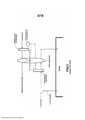
[0005] No sistema ilustrado na Figura 1, um ar fornecido puro ou de ar externo (ar ambiente) é passado através de um segmento do dispositivo de recuperação de energia (neste caso, uma roda de entalpia) para reduzir a umidade e temperatura do ar fornecido. O ar fornecido é então passada através de um evaporador/serpentina de resfriamento de um sistema de refrigeração convencional, para reduzir sua umidade e ainda, sua temperatura. O ar desumidificado e resfriado é então passado através da serpentina do condensador do sistema de refrigeração para elevar a temperatura do ar fornecido. Dessa forma, o ar quente e desumidificado é então fornecido através de um sistema de dutos diretamente para o espaço desejado.[0005] In the system illustrated in Figure 1, a fresh supply air or outside air (ambient air) is passed through a segment of the energy recovery device (in this case, an enthalpy wheel) to reduce the humidity and temperature of the supplied air. The supplied air is then passed through an evaporator/cooling coil of a conventional refrigeration system to reduce its humidity and temperature. The dehumidified and cooled air is then passed through the refrigeration system condenser coil to raise the supply air temperature. In this way, hot, dehumidified air is then supplied through a duct system directly to the desired space.
[0006] No sistema da Figura 1, o ar de exaustão é retirado do espaço com um ventilador ou ventoinha (não é ilustrado) e passado através de um segmento separado de um dispositivo de recuperação de energia, roda de entalpia. Como resultado, a temperatura e umidade do fluxo de ar de exaustão são aumentadas, e em seguida, a exaustão é rejeitada para a atmosfera. Este tipo de dispositivo da técnica anterior é eficaz em reduzir a umidade do ar fornecido e utilizando recuperação de energia, mas requer um resfriamento significativo para obter o desejado desempenho de desumidificação. Grande parte da energia utilizada para resfriar o ar para obter essa desumidificação, é revertida através da serpentina de aquecimento para eliminar o resfriamento em excesso do espaço.[0006] In the system of Figure 1, exhaust air is drawn from the space with a fan or fan (not shown) and passed through a separate segment of an energy recovery device, enthalpy wheel. As a result, the temperature and humidity of the exhaust air flow are increased, and then the exhaust is vented to the atmosphere. This type of prior art device is effective in reducing supply air humidity and utilizing energy recovery, but requires significant cooling to achieve the desired dehumidification performance. Much of the energy used to cool the air to achieve this dehumidification is reverted through the heating coil to eliminate excess cooling of the space.
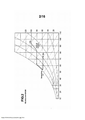
[0007] A figura 2 é um gráfico psicrométrico do sistema na figura 1, e fornece a análise psicrométrica dos efeitos de cada componente do sistema sobre o ar fornecido.[0007] Figure 2 is a psychrometric graph of the system in Figure 1, and provides a psychrometric analysis of the effects of each component of the system on the supplied air.
[0008] Neste sistema ilustrativo, o ar ambiente ou externo (OA) tem uma taxa de umidade de cerca de 220,46 g/kg (100 g/lb) e uma temperatura de cerca de 34,44 °C (94°F); após deixar a roda de recuperação de energia, que tem uma taxa de umidade de cerca de 176,37 g/kg (80 g/lb) e uma temperatura de cerca de 28,33 °C (83°F); após passar através da serpentina do evaporador, que tem uma taxa de umidade de cerca de 130,073 g/kg (59 g/lb) e uma temperatura de cerca de 11,66 °C (53°F) e, após deixar a serpentina do condensador que tem a mesma taxa de umidade, cerca de 130,073 g/kg (59 g/lb) e uma temperatura de cerca de 22,22 °C (72°F) .[0008] In this illustrative system, the ambient or outside air (OA) has a humidity rate of about 220.46 g/kg (100 g/lb) and a temperature of about 34.44 °C (94°F ); after leaving the energy recovery wheel, which has a moisture rate of about 176.37 g/kg (80 g/lb) and a temperature of about 28.33 °C (83 °F); after passing through the evaporator coil, which has a moisture rate of about 130.073 g/kg (59 g/lb) and a temperature of about 11.66°C (53°F) and, after leaving the evaporator coil. condenser that has the same moisture rate, about 130.073 g/kg (59 g/lb) and a temperature of about 22.22°C (72°F) .
[0009] Outra forma do sistema de condicionamento do condensador regenerado é ilustrado na figura 3 e também na figura 7 da Patente US 6.557.365 B2. Esse sistema usa uma serpentina de resfriamento DX, para o resfriamento e desumidificação do ar ambiente/externo antes de entrar em uma roda dessecante. O ar é então desumidificado e ainda aquecido com a roda dessecante antes de ser inicialmente fornecido ao espaço. Um fluxo de ar ambiente separado é utilizado como o fluxo de ar de regeneração, e é aquecido primeiro utilizando o calor do condensador do ciclo de refrigeração DX; o fluxo de ar aquecido, portanto, é então utilizado para conduzir a umidade para fora da roda dessecante. O fluxo de ar de regeneração coleta a umidade e a rejeita para a atmosfera. Muitos outros sistemas de desumidificação dessecante são comercialmente disponíveis, que utilizam outras fontes de calor para regenerar rodas dessecantes para fornecer ciclos de desumidificação e aquecimento para o ar fornecido. A grande maioria destes dispositivos requer elevadas temperaturas de regeneração para regenerar o dessecante.[0009] Another form of the regenerated condenser conditioning system is illustrated in figure 3 and also in figure 7 of US Patent 6,557,365 B2. This system uses a DX cooling coil to cool and dehumidify ambient/outside air before entering a desiccant wheel. The air is then dehumidified and further heated with the desiccant wheel before being initially supplied to the space. A separate ambient air stream is used as the regeneration air stream, and it is heated first using the condenser heat from the DX refrigeration cycle; the heated airflow, therefore, is then used to drive moisture out of the desiccant wheel. The regeneration airflow collects moisture and rejects it to the atmosphere. Many other desiccant dehumidification systems are commercially available that use other heat sources to regenerate desiccant wheels to provide dehumidification and heating cycles for the supplied air. The vast majority of these devices require high regeneration temperatures to regenerate the desiccant.
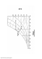
[0010] A figura 4 ilustra o gráfico psicrométrico para o sistema da figura 3, e ilustra o efeito dos componentes do sistema sobre o sistema de ar fornecido. Como pode ser observado, o ar externo fornecido à serpentina do evaporador tem uma temperatura de cerca de 33,88 °C (93°F) e taxa de umidade de cerca de 220,46 g/kg (100 g/lb). Depois de deixar a serpentina do evaporador, o ar, tem uma temperatura de cerca de 16,66 °C (62°F) e taxa de umidade de cerca de 171,96 g/kg (78 g/lb). Após deixar a roda dessecante, dito ar, tem uma temperatura de cerca de 22,22 °C (72°F) e uma taxa de umidade de cerca de 127,87 g/kg (58 g/lb).[0010] Figure 4 illustrates the psychrometric chart for the system of Figure 3, and illustrates the effect of system components on the air supply system. As can be seen, the outside air supplied to the evaporator coil has a temperature of about 33.88°C (93°F) and a humidity rate of about 220.46 g/kg (100 g/lb). After leaving the evaporator coil, the air has a temperature of about 16.66°C (62°F) and a humidity rate of about 171.96 g/kg (78 g/lb). After leaving the desiccant wheel, called air, it has a temperature of about 22.22°C (72°F) and a humidity rate of about 127.87 g/kg (58 g/lb).
[0011] A figura 5 ilustra outra técnica anterior de sistema de condicionador de ar que, neste caso, utiliza um sistema dessecante de condensador de regeneração com pré- tratamento de recuperação da entalpia do ar fornecido. Como pode ser observado, o ar fornecido fresco do ambiente externo é passado através de um setor de um dispositivo de recuperação de entalpia, desumidificado e resfriando, é então passado na serpentina de resfriamento de um sistema convencional de refrigeração DX, reduzindo ainda mais sua umidade e temperatura. Assim, o fluxo do ar fornecido, resfriado e seco, é então passado através de um dispositivo dessecante, o qual é desumidificado, aquecido e posteriormente fornecido para o espaço através de um sistema de dutos.[0011] Figure 5 illustrates another prior art air conditioner system which, in this case, uses a regeneration condenser desiccant system with pre-treatment to recover the enthalpy of the supplied air. As can be seen, fresh supply air from the outdoor environment is passed through a section of an enthalpy recovery device, dehumidified and cooled, then passed into the cooling coil of a conventional DX refrigeration system, further reducing its humidity and temperature. Thus, the flow of supplied air, cooled and dried, is then passed through a desiccant device, which is dehumidified, heated and subsequently supplied to the space through a system of ducts.
[0012] O ar de exaustão é extraído do espaço com um ventilador ou ventoinha (não é ilustrado) e passado através de outra seção do dispositivo de recuperação de entalpia o qual o ar de exaustão é aquecido e umidificado e, em seguida, rejeitado para a atmosfera. Neste sistema, um fluxo de ar separado do ambiente é aquecido, utilizando a serpentina do condensador do sistema de refrigeração, e então, utilizado como o fluxo de ar de regeneração. O fluxo de ar de regeneração é passado através de outra seção do dispositivo dessecante, resfriado e umidificado, e em seguida, rejeitado para a atmosfera.[0012] The exhaust air is drawn from the space with a fan or fan (not shown) and passed through another section of the enthalpy recovery device which exhaust air is heated and humidified and then rejected to the atmosphere. In this system, a separate ambient air stream is heated using the refrigeration system condenser coil and then used as the regeneration air stream. The regeneration airflow is passed through another section of the desiccant device, cooled and humidified, and then rejected to atmosphere.
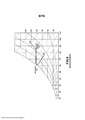
[0013] A figura 6 ilustra o gráfico psicrométrico do sistema da figura 5 e ilustra os efeitos de cada componente do sistema sobre o ar fornecido. Como pode ser observado, o ar fornecido externo, inicialmente tem uma taxa de umidade de cerca de 220,46 g/kg (100 g/lb) e temperatura de cerca de 33, 88 °C (93°F), após passar pela roda de entalpia, o ar fornecido tem uma taxa de umidade de cerca de 185,19 g/kg (84 g/lb) e uma temperatura de cerca de 28,88 °C (84°F). Após a passagem através da serpentina do evaporador, o ar fornecido, tem uma taxa de umidade de cerca de 171,96 g/kg (78 g/lb) e uma temperatura de cerca de 16,66 °C (62°F). Após a passagem através da roda dessecante, dito ar fornecido, tem uma taxa de umidade de cerca de 127,87 g/kg (58 g/lb) e temperatura de cerca de 22,22 °C (72°F), como fornecido ao espaço.[0013] Figure 6 illustrates the psychrometric chart of the system in Figure 5 and illustrates the effects of each component of the system on the supplied air. As can be seen, the external supply air initially has a humidity rate of about 220.46 g/kg (100 g/lb) and a temperature of about 33.88°C (93°F) after passing through the Enthalpy wheel, the supply air has a humidity rate of about 185.19 g/kg (84 g/lb) and a temperature of about 28.88 °C (84 °F). After passing through the evaporator coil, the supplied air has a humidity rate of about 171.96 g/kg (78 g/lb) and a temperature of about 16.66 °C (62 °F). After passing through the desiccant wheel, called supply air, it has a moisture rate of about 127.87 g/kg (58 g/lb) and a temperature of about 22.22°C (72°F), as supplied. to space.
[0014] Em comparação aos sistemas convencionais de condicionador de ar e processos como descrito acima, a presente invenção tem vantagens significativas no tratamento de ar fresco ou externo para alimentar o ar à temperatura do espaço e com a umidade igual ou inferior ao do espaço. A vantagem mais significativa, é o baixo consumo de energia. Mais especificamente, a presente invenção reduz a energia requerida em 30 a 75% em comparação com as outras técnicas disponíveis.[0014] Compared to conventional air conditioner systems and processes as described above, the present invention has significant advantages in treating fresh or outdoor air to supply air at the temperature of the space and with the humidity equal to or less than that of the space. The most significant advantage is low power consumption. More specifically, the present invention reduces the energy requirement by 30 to 75% compared to other available techniques.
[0015] Um benefício adicional significativo da invenção é a capacidade de fornecer condições de ar fornecido com baixa umidade (ponto de orvalho ou g/lb (taxa de umidade absoluta)) que algumas outras técnicas. Mais particularmente, sistemas de desumidificação baseados em serpentina têm problemas com a formação de gelo sobre as serpentinas do evaporador, assim, proporcionando baixas temperaturas da serpentina a fim de proporcionar condições de baixa umidade. A presente invenção, por outro lado oferece a possibilidade de fornecer condições de ar fornecido com baixa umidade (ponto de orvalho ou g/lb), pela utilização de um ciclo de desumidificação dessecante após a serpentina de resfriamento.[0015] A significant additional benefit of the invention is the ability to provide supply air conditions with lower humidity (dew point or g/lb (absolute humidity rate)) than some other techniques. More particularly, coil-based dehumidification systems have problems with the formation of ice on the evaporator coils, thus providing low coil temperatures in order to provide low humidity conditions. The present invention on the other hand offers the possibility of providing supply air conditions with low humidity (dew point or g/lb), by using a desiccant dehumidification cycle after the cooling coil.
[0016] É um objetivo da presente invenção, tratar o ar externo ou fresco, do ar ambiente fornecido e desumidificar e resfriar o ar a partir da condição do ambiente externo, para a condição de ar desejada do espaço. ASHRAE definiu que as condições de conforto para uma construção estão entre 22,77 °C (73°F) e 235,55 °C (78°F) de temperatura e cerca de 50% de umidade relativa ou 121,25 g/kg (55 g/lb) de ar a 156,52 g/kg (71 g/lb) de ar. Em particular, a presente invenção é particularmente adequada para tratar ar quente e úmido do sudeste dos Estados Unidos e de outros climas quentes e úmidos ao redor do mundo, com as condições do ar ambiente variando de 15,55 °C (60°F) a 40,55 °C (105°F) ou mais e um teor de umidade de 70 a 1176,37 g/kg (80 g/lb) e liberar o ar tratado na temperatura do espaço, e umidade igual ou inferior a do espaço, geralmente na faixa de cerca de 21,11 °C (70°F) a 29,44 °C (85°F) de temperatura e um nível de umidade de cerca de 99,20 g/kg (45 g/lb) a cerca de 156,52 g/kg (71 g/lb). Faixas um pouco menores e maiores que os propostos pela ASHRAE também podem ser obtidas pela presente invenção, quando as condições do espaço de projeto variam das condições determinadas pela ASHRAE.[0016] It is an objective of the present invention, to treat outdoor or fresh air, from the ambient air supplied and to dehumidify and cool the air from the condition of the external environment, to the desired air condition of the space. ASHRAE has defined comfort conditions for a building to be between 22.77 °C (73 °F) and 235.55 °C (78 °F) temperature and about 50% relative humidity or 121.25 g/kg (55 g/lb) of air to 156.52 g/kg (71 g/lb) of air. In particular, the present invention is particularly suitable for treating hot and humid air from the southeastern United States and other hot and humid climates around the world, with ambient air conditions ranging from 15.55 °C (60 °F) at 40.55 °C (105°F) or more and a moisture content of 70 to 1176.37 g/kg (80 g/lb) and release the treated air at room temperature, and humidity equal to or less than the space, generally in the range of about 21.11°C (70°F) to 29.44°C (85°F) temperature and a humidity level of about 99.20 g/kg (45 g/lb) ) at about 156.52 g/kg (71 g/lb). Slightly smaller and larger ranges than those proposed by ASHRAE can also be obtained by the present invention, when the design space conditions vary from the conditions determined by ASHRAE.
[0017] Outro objeto da presente invenção é fornecer esse tratamento de ar ambiente, ar externo e ar fresco de forma muito eficiente, com menor entrada de energia que a maioria dos sistemas de tratamentos atualmente disponíveis.[0017] Another object of the present invention is to provide this treatment of ambient air, outside air and fresh air very efficiently, with less energy input than most treatment systems currently available.
[0018] No entanto, outro objeto da presente invenção é fornecer um sistema que pode proporcionar diferentes capacidades de desumidificação e refrigeração, para reagir e superar diferentes cargas de refrigeração e desumidificação do ar fornecido fresco ou externo e/ou da própria construção. Outro objetivo da presente invenção é fornecer o aquecimento, do ar exterior ou ar fornecido fresco, com a utilização de um dispositivo de recuperação de energia durante períodos de clima frio para reduzir a exigência de entrada de ar aquecido para a condição de temperatura do espaço. Mais especificamente, o sistema utiliza ar de exaustão com calor transferido para o ar fornecido fresco ou ao ar externo, com um trocador de calor de recuperação de energia para aumentar, substancialmente, a temperatura e/ou a umidade do ar, antes de ser aquecido por um dispositivo de aquecimento. Assim, uma temperatura, tal como -23,33 °C (-10°F) seria aquecida para aproximadamente, a uma temperatura de 10 °C (50°F) ou superior, conforme necessário.[0018] However, another object of the present invention is to provide a system that can provide different dehumidification and refrigeration capabilities, to react and overcome different refrigeration and dehumidification loads of fresh or external supplied air and/or the building itself. Another object of the present invention is to provide heating of outdoor air or fresh supply air using an energy recovery device during periods of cold weather to reduce the heated air input requirement for the space temperature condition. More specifically, the system uses exhaust air with heat transferred to fresh supply air or outside air, with an energy recovery heat exchanger to substantially increase the temperature and/or humidity of the air before it is heated. by a heating device. Thus, a temperature such as -23.33 °C (-10 °F) would be heated to approximately 10 °C (50°F) or higher as needed.
[0019] De acordo com um aspecto da invenção, um sistema de condicionador de ar incluindo um meio para recuperar energia a partir de um fluxo de ar de exaustão pela passagem do fluxo de ar de exaustão através de um dispositivo de recuperação de energia, como uma roda de entalpia. O ar ambiente fornecido, fresco, externo são passados sobre o outro “lado" do dispositivo de recuperação de energia. O dispositivo de recuperação de energia transfere energia de um fluxo de ar para o outro, sem a transferência de ar através do dispositivo. Isto permite uma redução da temperatura e, em alguns dispositivos, a redução na umidade do ar fornecido, quando a condição do ambiente é mais quente e mais úmida do que a condição do espaço. O dispositivo permite também o aumento da temperatura e, em alguns dispositivos, o aumento da umidade do ar fornecido quando a condição do ambiente é mais fria e seca que a condição de espaço.[0019] According to one aspect of the invention, an air conditioning system including a means for recovering energy from an exhaust air stream by passing the exhaust air stream through an energy recovery device such as an enthalpy wheel. The supplied, fresh, outside ambient air is passed over the other “side” of the energy recovery device. The energy recovery device transfers energy from one air stream to the other, without transferring air through the device. allows a reduction in temperature and, in some devices, a reduction in the humidity of the supplied air, when the ambient condition is hotter and more humid than the space condition. The device also allows an increase in temperature, and in some devices , the increase in humidity of the supplied air when the ambient condition is cooler and drier than the space condition.
[0020] De acordo com outro aspecto da invenção, o sistema da presente invenção utiliza uma serpentina de resfriamento para diminuir a temperatura e umidade do ar fornecido antes de fornecê-lo para o espaço em que ele é necessário. Um dispositivo de desumidificação dessecante que utiliza o calor de reativação a partir de um sistema de refrigeração fornece uma desumidificação adicional, enquanto aumenta a temperatura do ar fornecido. A refrigeração adicional do ar é uma opção para prover uma temperatura menor de ar fornecido contornando a sensibilidade da carga na construção interna, se desejado.[0020] According to another aspect of the invention, the system of the present invention uses a cooling coil to decrease the temperature and humidity of the supplied air before supplying it to the space in which it is needed. A desiccant dehumidification device that utilizes reactivation heat from a refrigeration system provides additional dehumidification while increasing the temperature of the supply air. Additional air cooling is an option to provide a lower supply air temperature by bypassing the load sensitivity in the interior construction, if desired.
[0021] Sistemas de acordo com a presente invenção também podem utilizar a exaustão do ar que passou através de um dispositivo de recuperação de energia para fornecer uma fonte de ar de reativação para o ciclo de desumidificação dessecante. Uma serpentina de condensador a partir de um sistema de refrigeração convencional é utilizada para aumentar a temperatura de ar de exaustão e, em seguida, passar este ar através de outro segmento do dispositivo dessecante, para a regeneração do dispositivo dessecante. O fluxo de ar de exaustão é resfriado e umidificado durante este processo de regeneração permitindo que ele seja passado através de uma serpentina de condensador adicional, para receber o calor adicional rejeitado a partir do sistema de refrigeração. Um dispositivo de refrigeração evaporativo também pode ser adicionado antes da segunda serpentina do condensador para diminuir a exaustão do ar que entra na segunda serpentina do condensador para melhorar a eficiência dos sistemas de refrigeração e/ou aumentar a capacidade de rejeição de calor do condensador.[0021] Systems in accordance with the present invention may also use exhaust air that has passed through an energy recovery device to provide a source of reactivation air for the desiccant dehumidification cycle. A condenser coil from a conventional refrigeration system is used to increase the exhaust air temperature and then pass this air through another segment of the desiccant device for regeneration of the desiccant device. The exhaust air stream is cooled and humidified during this regeneration process allowing it to be passed through an additional condenser coil to receive the additional heat rejected from the refrigeration system. An evaporative cooling device can also be added before the second condenser coil to decrease exhaust air entering the second condenser coil to improve the efficiency of the refrigeration systems and/or increase the heat rejection capacity of the condenser.
[0022] O acima exposto, e outros objetivos, características e vantagens da presente invenção, serão evidentes na descrição detalhada das construções ilustrativas da mesma abaixo, as quais deverão ser lidas em conjunto com os desenhos que acompanham, onde:[0022] The above, and other objectives, characteristics and advantages of the present invention, will be evident in the detailed description of the illustrative constructions thereof below, which should be read in conjunction with the accompanying drawings, where:
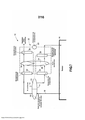
[0023] A figura 1 ilustra um gráfico esquemático de uma técnica anterior convencional de recuperação de energia de condicionador de ar ou ventilador, usando um sistema de resfriamento DX e um condensador de reaquecimento;[0023] Figure 1 illustrates a schematic graph of a conventional prior art air conditioner or fan energy recovery using a DX cooling system and a reheat condenser;
[0024] A figura 2 ilustra um gráfico psicrométrico descrevendo os efeitos dos componentes do sistema de fluxo de ar fornecido do sistema ilustrado na Figura 1;[0024] Figure 2 illustrates a psychrometric graph describing the effects of the components of the air flow system provided from the system illustrated in Figure 1;
[0025] A figura 3 ilustra um gráfico esquemático da técnica anterior, de um sistema de condensador reativado dessecante;[0025] Figure 3 illustrates a schematic graph of the prior art of a desiccant reactivated condenser system;
[0026] A figura 4 ilustra um gráfico psicrométrico descrevendo os efeitos dos componentes do sistema de fluxo de ar fornecido do sistema ilustrado na Figura 3;[0026] Figure 4 illustrates a psychrometric chart describing the effects of the system components provided air flow from the system illustrated in Figure 3;
[0027] A figura 5 ilustra um gráfico esquemático da técnica anterior, de um sistema de condensador reativado dessecante, utilizando um sistema de pré-tratamento de recuperação da energia de entalpia;[0027] Figure 5 illustrates a schematic graph of the prior art of a desiccant reactivated condenser system using an enthalpy energy recovery pretreatment system;
[0028] A figura 6 ilustra um gráfico psicrométrico descrevendo os efeitos dos componentes do sistema de fluxo de ar fornecido do sistema ilustrado na Figura 5;[0028] Figure 6 illustrates a psychrometric graph describing the effects of the system components provided air flow from the system illustrated in Figure 5;
[0029] A figura 7 ilustra uma vista esquemática de um sistema de condicionador de ar de acordo com a presente invenção;[0029] Figure 7 illustrates a schematic view of an air conditioner system according to the present invention;
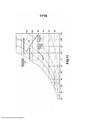
[0030] A figura 8 ilustra um gráfico psicrométrico mostrando os efeitos dos componentes do fluxo de ar fornecido no sistema ilustrado na Figura 7;[0030] Figure 8 illustrates a psychrometric graph showing the effects of airflow components provided in the system illustrated in Figure 7;
[0031] A figura 9 ilustra um gráfico psicrométrico mostrando os efeitos dos componentes do fluxo de ar de exaustão no sistema ilustrado na Figura 7;[0031] Figure 9 illustrates a psychrometric graph showing the effects of exhaust airflow components in the system illustrated in Figure 7;
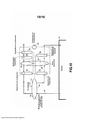
[0032] A figura 10 ilustra, esquematicamente, uma segunda construção da presente invenção;[0032] Figure 10 schematically illustrates a second construction of the present invention;
[0033] A figura 11 ilustra um gráfico psicrométrico mostrando os efeitos dos componentes no fluxo de ar de exaustão no sistema ilustrado na figura 10;[0033] Figure 11 illustrates a psychrometric graph showing the effects of components on the exhaust air flow in the system illustrated in Figure 10;
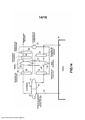
[0034] A figura 12 ilustra esquematicamente, uma terceira construção da invenção;[0034] Figure 12 schematically illustrates a third construction of the invention;
[0035] A figura 13 ilustra esquematicamente, uma quarta construção da invenção;[0035] Figure 13 schematically illustrates a fourth construction of the invention;
[0036] A figura 14 ilustra esquematicamente, uma quinta construção da invenção;[0036] Figure 14 schematically illustrates a fifth construction of the invention;
[0037] A figura 15 ilustra esquematicamente, uma sexta construção da invenção;[0037] Figure 15 schematically illustrates a sixth construction of the invention;
[0038] A figura 16 ilustra esquematicamente, uma sétima construção da invenção; e[0038] Figure 16 schematically illustrates a seventh construction of the invention; and
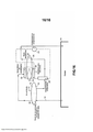
[0039] A figura 17 ilustra esquematicamente, uma oitava construção da invenção.[0039] Figure 17 schematically illustrates an eighth construction of the invention.
[0040] Referindo-se agora ao desenho em detalhe e inicialmente a figura 7, um sistema de condicionamento de ar 10, de acordo com uma configuração da invenção é ilustrado, na qual um fluxo de ar ambiente 12 é tratado a condições de temperatura e umidade desejadas para uso em um quarto, recinto ou espaço 14. Na construção ilustrada, o sistema é utilizado em áreas onde o ar ambiente externo tem uma alta temperatura e alto teor de umidade ou a razão, como descrito acima. A figura 7 é um desenho esquemático e deve ser compreendido por um técnico no assunto que os fluxos de ar descritos estão contidos em dutos de trabalho apropriados e movidos com ventiladores apropriados, os quais não são ilustrados.[0040] Referring now to the detailed drawing and initially to Figure 7, an
[0041] Como pode ser visto na figura 7, o ar fornecido 12, ambiente, fresco, externo, é primeiro passado através de uma seção 13, de um dispositivo de recuperação de energia 16. O ar é resfriado e desumidificado quando passa através do dispositivo de recuperação de energia 16. Como descrito acima, esse dispositivo pode ser uma roda de entalpia rotativa convencional ou outro tipo de trocador de calor, tal como um trocador de calor, tal como um tubo de calor (“heat pipe”), para trocar calor entre o fluxo de ar fornecido 12 e um fluxo de ar de exaustão 18, retirado a partir do espaço 14. No caso de usar um tubo de calor, o ar ambiente deve ser resfriado, mas não desumidificado.[0041] As can be seen in Figure 7,
[0042] O fluxo de ar fornecido resfriado e desumidificado é então passado através da serpentina do evaporador ou serpentina de resfriamento 20 de uma unidade convencional de refrigeração DX 22, a qual inclui um compressor 23, para reduzir ainda mais a sua temperatura e umidade. O ar fornecido então passa através de um segmento de um dispositivo dessecante 26, tal como uma roda dessecante ondulada rotativa revestida de sílica convencional, para reduzir ainda mais a sua umidade, enquanto aumenta sua temperatura. Neste ponto, o ar fornecido é igual ou próximo à temperatura desejada no espaço 14 e é igual ou inferior a umidade desejada nesse espaço.[0042] The cooled and dehumidified supply air flow is then passed through the evaporator coil or cooling
[0043] Quando o ar fornecido ao sair da roda dessecante 26 tem uma taxa de umidade menor do que o desejado no espaço 14, o ar fornecido irá fornecer capacidade de desumidificação para o espaço para superar a carga latente interna. O ar fornecido pode ser fornecido diretamente para o espaço naquele momento ou pode ainda ser resfriado utilizando uma serpentina de evaporador ou resfriamento 28 entre a roda dessecante e o espaço 14 para fornecer um efeito de resfriamento do espaço e superar a carga sensível interna. O fluxo de ar de exaustão 18 é retirado a partir do espaço 14 com um ventilador ou ventoinha (não é ilustrado), e depois passado sobre outra seção 30 do dispositivo de recuperação de energia 16. A exaustão do ar é aquecida pelo calor absorvido na seção 13 e umidificado ao passar pela seção 30 e, em seguida, é passado através de uma serpentina do condensador 32 do sistema de refrigeração 22 para aumentar sua temperatura. O ar de exaustão que sai do condensador 32 tem uma temperatura mais elevada do que quando entrou e é então utilizado para regenerar a roda dessecante 26, pela passagem do ar de exaustão através de uma seção separada 34 do dispositivo dessecante. O fluxo de ar de exaustão é resfriado e umidificado durante este processo de regeneração. Agora o ar de exaustão refrigerado, pode então ser utilizado para passar sobre uma segunda serpentina do condensador 36 no sistema 22 para recuperar ainda mais o ar do sistema de refrigeração e então rejeitá-lo na atmosfera.[0043] When the supplied air exiting the
[0044] Como será apreciado pelos técnicos no assunto que, o sistema da presente invenção utiliza o fluxo de ar de exaustão para recuperar calor a partir do fluxo de ar fornecido ambiente e para regenerar a roda dessecante. Dito sistema, também é utilizado para recuperar ou absorver o calor do sistema de refrigeração através de condensadores 32 e/ou 36. Esse potencial de rejeição de calor do fluxo de ar de exaustão é aumentado pelo efeito de resfriamento evaporativo no processo de regeneração dessecante. Este fluxo de exaustão/regeneração de ar 18 pode ser igual ou inferior que o fluxo de ar fornecido em termos de volume, conforme desejado, utilizando controles adequados. Este é um aspecto importante, que é de conhecimento que a construção cautelosa de condicionador de ar, requer uma pressão de ar positiva. Para obter a pressão de ar positiva, a quantidade de ar fornecido fresco ou externo, deve ser igual ou maior que a quantidade de ar de exaustão.[0044] As will be appreciated by those skilled in the art that, the system of the present invention uses exhaust airflow to recover heat from the ambient supplied airflow and to regenerate the desiccant wheel. Said system is also used to recover or absorb heat from the refrigeration system through
[0045] A figura 8 é um gráfico psicrométrico, o qual ilustra o efeito dos componentes da invenção ilustrados na figura 7, sobre o fornecimento do fluxo de ar 12. Como pode ser visto, os efeitos são semelhantes aos obtidos no dispositivo da técnica anterior da figura 5, embora a presente invenção possibilite a inclusão de uma serpentina de resfriamento 28 adicional, para tratamento do fluxo de ar fornecido depois de deixar a roda dessecante 26. No entanto, ao contrário da figura 5, o sistema da presente invenção, recupera o calor desperdiçado no fluxo de escapamento de ar do sistema da figura 5. Assim, a fluxo de ar de exaustão, saindo o espaço 14 e entrando no segmento 30 da roda de entalpia 16, tem uma temperatura de cerca de 22,22 °C (72°F) e uma taxa de umidade de cerca de 141,09 g/kg (64 g/lb), ao deixar a roda de entalpia, tem uma temperatura de cerca de 28, 33 °C (83°F) e uma taxa de umidade de 176, 37 g/kg (80 g/lb). À medida que passa através da serpentina do condensador 32, o fluxo de ar de exaustão absorve o calor rejeitado da serpentina de modo que quando ele sai da serpentina e entra no segmento de regeneração de 34, da roda dessecante, o fluxo de ar de exaustão tem uma temperatura de cerca de 42,22 °C (108°F) e uma taxa de umidade de 176,37 g/kg (80 g/lb).[0045] Figure 8 is a psychrometric graph, which illustrates the effect of the components of the invention illustrated in Figure 7 on the supply of
[0046] Depois de passar através do segmento 34 da roda dessecante e antes de entrar na serpentina do condensador 36, o fluxo de ar de exaustão tem uma temperatura de cerca de 26,66 °C (80°F) e uma taxa de umidade de cerca de 268,96 g/kg (122 g/lb).[0046] After passing through
[0047] Quando passa através da serpentina do condensador 36, o fluxo de ar de exaustão, absorve o calor rejeitado por essa serpentina e sua temperatura sobe para cerca de 42,22 °C (108°F) ou superior, antes de ser rejeitado para a atmosfera.[0047] When passing through the
[0048] A figura 10 ilustra outra construção da invenção ilustrada na figura 7 e os mesmos numerais de referência são utilizados para identificar as partes semelhantes. Nesta construção, um dispositivo de resfriamento evaporativo 38 é adicionado entre a roda dessecante 26 e a segunda serpentina do condensador 36 no fluxo de ar de exaustão. O dispositivo de resfriamento evaporativo pode ser de construção convencional, por exemplo, utilizando, materiais em chapa onduladas entrelaçadas de construção conhecida através da qual o fornecimento de água é passado através ou no contra fluxo da corrente de ar para resfriar o fluxo de ar. Esse resfriamento evaporativo adicional do fluxo de ar de exaustão promove a temperatura mais baixa. O fluxo de exaustão nesse ponto tem uma temperatura menor e uma capacidade adicional de rejeição de calor quando ele entra na serpentina do condensador 36, permitindo, assim, uma menor e mais eficiente temperatura de condensação e redução da pressão de descarga de refrigeração.[0048] Figure 10 illustrates another construction of the invention illustrated in Figure 7 and the same reference numerals are used to identify similar parts. In this construction, an
[0049] A figura 11 é um gráfico psicrométrico ilustrando os efeitos da invenção, como ilustrado na figura 10. Como um resultado da utilização do dispositivo de resfriamento evaporativo adicionado entre a roda dessecante 26 e o segundo condensador 36, a temperatura de exaustão do fluxo de ar é reduzida ainda à cerca de 25 °C (77°F) e sua taxa de umidade aumentada à cerca de 286,60 g/kg (130 g/lb), para fornecer refrigeração adicional e baixa temperatura ao entrar no segundo condensador.[0049] Figure 11 is a psychrometric graph illustrating the effects of the invention, as illustrated in Figure 10. As a result of using the evaporative cooling device added between the
[0050] A presente invenção proporciona vantagens significativas sobre a técnica anterior. A utilização de um único fluxo de ar para exaustão, regeneração e rejeição de calor do condensador, diminui significativamente a potência do ventilador requerida (por movimento de vários fluxos de ar) para realizar estas três funções. Enquanto o sistema não exige um aumento da pressão estática total para superar os diferentes trocadores de calor, o fluxo de ar total é substancialmente reduzido. Quando a potência do ventilador é proporcional ao quadrado da pressão estática e ao cubo do fluxo de ar, a redução do fluxo de ar é um fator muito importante na redução das exigências fornecido do ventilador.[0050] The present invention provides significant advantages over the prior art. The use of a single airflow for exhaust, regeneration and condenser heat rejection significantly decreases the fan power required (by moving multiple airflows) to perform these three functions. While the system does not require an increase in total static pressure to overcome the different heat exchangers, the total airflow is substantially reduced. When fan power is proportional to the square of the static pressure and the cube of the airflow, reducing airflow is a very important factor in reducing fan supplied requirements.
[0051] Adicionalmente, o uso de um único fluxo de ar para fornecer essas funções, também oferece os níveis mais baixos de umidade para a roda dessecante para o processo de reativação. A construção do ar de exaustão do ar é feita a partir do espaço considerando o teor de umidade no espaço. Em seguida, passa através de um dispositivo de recuperação de energia. Este dispositivo também não aumenta a sua umidade (quando se utiliza um dispositivo de recuperação de calor sensível) ou aumenta em certa proporção entre a condição externa e a condição interna, baseada na eficiência do dispositivo de recuperação de entalpia. Em ambos os casos a umidade deixada no dispositivo de recuperação de energia e entrando na roda dessecante é menor do que a condição externa. A temperatura de ar de exaustão é na mesma temperatura, independentemente da umidade. A temperatura é determinada pelo processo de recuperação de exaustão, onde a troca de temperatura é independente do nível de umidade e do calor do condensador adicionado, novamente, independente de umidade. Como a roda dessecante atua como um trocador de umidade relativa, uma condição de baixa umidade em um fluxo de ar com determinada temperatura, proporciona uma umidade relativa baixa. Assim, a menor umidade no ar dá ao dispositivo dessecante, aumento da capacidade através da regeneração aperfeiçoada.[0051] Additionally, the use of a single airflow to provide these functions also provides the lowest moisture levels for the desiccant wheel for the reactivation process. The construction of exhaust air is made from the space considering the moisture content in the space. It then passes through an energy recovery device. This device also does not increase its humidity (when using a sensitive heat recovery device) or increase by a certain proportion between the external condition and the internal condition, based on the efficiency of the enthalpy recovery device. In both cases the moisture left in the energy recovery device and entering the desiccant wheel is less than the external condition. The exhaust air temperature is the same temperature regardless of humidity. The temperature is determined by the exhaust recovery process, where the temperature change is independent of the moisture level and the added condenser heat, again independent of moisture. Since the desiccant wheel acts as a relative humidity exchanger, a low humidity condition in an air stream at a certain temperature provides a low relative humidity. Thus, the lower moisture in the air gives the desiccant device increased capacity through improved regeneration.
[0052] Outras vantagens da invenção sobre a técnica anterior são relacionadas com a temperatura e o ciclo de refrigeração do condensador e capacidade de rejeição de calor. O calor de condensador deve ser rejeitado para a atmosfera. A temperatura do fluxo de ar de exaustão da presente invenção é inferior à temperatura ambiente. Assim, com relação à umidade, o ar de exaustão é retirado do espaço e percorre através de um dispositivo de recuperação de energia. Sua temperatura é aumentada em uma fração da diferença entre a temperatura do espaço e da temperatura externa. A temperatura de partida é algumas vezes uma temperatura menor do que a do ambiente externo. Isso oferece dois benefícios. Primeiro, a taxa de fluxo de ar necessário para rejeitar o calor da serpentina do condensador para o fluxo de ar é reduzida, devido à sua baixa temperatura e a maior diferença entre a temperatura refrigerante que entra no condensador e a temperatura do ar que entra no condensador. A redução do fluxo de ar exigido, também reduz a exigência da potência do ventilador. É de certa forma, incluídos na exigência de redução do fluxo de ar discutido acima. Adicionalmente, a menor temperatura do ar de entrada para o condensador, permite uma menor temperatura de refrigeração que deixa o condensador e proporciona uma menor pressão de descarga. Com a menor pressão de descarga, o volume de trabalho do compressor deve ser elevado à pressão do refrigerante a ser reduzida permitindo o compressor a operar com um menor consumo de energia.[0052] Other advantages of the invention over the prior art are related to the temperature and refrigeration cycle of the condenser and heat rejection capability. Condenser heat must be rejected to atmosphere. The temperature of the exhaust air flow of the present invention is below ambient temperature. Thus, with respect to humidity, the exhaust air is drawn from the space and passed through an energy recovery device. Its temperature is increased by a fraction of the difference between space temperature and outside temperature. The starting temperature is sometimes a temperature lower than that of the outside environment. This offers two benefits. First, the air flow rate required to reject heat from the condenser coil to the air flow is reduced, due to its low temperature and the greater difference between the refrigerant temperature entering the condenser and the temperature of the air entering the condenser. condenser. Reducing the required airflow also reduces the fan power requirement. It is somewhat included in the airflow reduction requirement discussed above. Additionally, the lower inlet air temperature to the condenser allows for a lower refrigeration temperature that leaves the condenser and provides a lower discharge pressure. With the lower discharge pressure, the working volume of the compressor must be raised with the refrigerant pressure being reduced allowing the compressor to operate with less energy consumption.
[0053] No entanto, outro aprimoramento da presente invenção é a capacidade e eficiência do fluxo de ar de exaustão para rejeitar mais calor no segundo condensador. O efeito de resfriamento por evaporação da roda dessecante reduz a temperatura de retorno a uma temperatura que permite que o mesmo fluxo de ar realize a rejeição de mais calor. Este novamente reduz o fluxo de ar total e proporciona a redução da potência do ventilador. A adição de um dispositivo de resfriamento evaporativo antes do segundo condensador, reduz ainda a temperatura para proporcionar a mesma eficiência para o segundo condensador como discutido acima para o primeiro condensador. Isto dá ao segundo condensador a capacidade de rejeitar mais calor a um menor fluxo de ar e economizar energia do ventilador. Ele também diminui a temperatura e reduz a pressão na cabeça do circuito de refrigeração, reduzindo a potência do compressor.[0053] However, another improvement of the present invention is the ability and efficiency of the exhaust air flow to reject more heat in the second condenser. The evaporative cooling effect of the desiccant wheel reduces the return temperature to a temperature that allows the same airflow to reject more heat. This again reduces the total airflow and provides the fan power reduction. The addition of an evaporative cooling device before the second condenser further reduces the temperature to provide the same efficiency for the second condenser as discussed above for the first condenser. This gives the second condenser the ability to reject more heat at less airflow and save fan energy. It also lowers the temperature and reduces the pressure in the head of the refrigeration circuit, reducing compressor power.
[0054] Adicionalmente, os ganhos de eficiência acima, ainda podem ser alcançados quando uma roda dessecante é utilizada como o dispositivo dessecante 26, uma vez que a velocidade de rotação da roda pode ser controlada para aumentar ou diminuir o aquecimento e desumidificação para controlar a temperatura e a umidade do fluxo de ar fornecido.[0054] Additionally, the above efficiency gains can still be achieved when a desiccant wheel is used as the
[0055] As figuras de 12 a 14 ilustram outras construções da invenção, como ilustrado na figura 10, novamente usando os mesmos números de referência para as partes correspondentes. Em cada uma das construções, um ou mais desvios de fluxo de ar são providos, utilizando dutos de trabalho convencionais, defletores e controles para seletivamente desviar uma porção de um ou ambos fluxos de ar em torno da roda dessecante.[0055] Figures 12 to 14 illustrate other constructions of the invention, as illustrated in Figure 10, again using the same reference numerals for corresponding parts. In each of the constructions, one or more airflow bypasses are provided, utilizing conventional working ducts, deflectors and controls to selectively bypass a portion of one or both of the airflows around the desiccant wheel.
[0056] A figura 12 ilustra o uso de um bypass 42 para direcionar uma parte do fluxo de ar fornecido em torno da seção de desumidificação da roda dessecante 26.[0056] Figure 12 illustrates the use of a
[0057] A figura 13 ilustra o uso do bypass 42 junto com um bypass 44, o qual desvia uma parte do fluxo de ar de exaustão em torno da seção de regeneração 34 da roda dessecante. A figura 14 simplesmente ilustra o uso de um único bypass 44 na seção de regeneração de 34 da roda dessecante.[0057] Figure 13 illustrates the use of
[0058] Fornecer uma ou mais “bypass’s” em torno de uma roda dessecante, permite diversas vantagens. Modulando o bypass em ambos os lados, fornecimento ou regeneração, fornece a capacidade de modulação dos efeitos dessecantes sobre o fluxo de ar fornecido. Adicionalmente, a queda de pressão da roda dessecante pode ser evitada durante as épocas quando a desumidificação não é necessária, permitindo a redução de energia do ventilador requerida e uma operação mais eficiente. Isto também permite uma maior flexibilidade no projeto da unidade, provendo a capacidade para a unidade fornecer mais ar do que a roda dessecante pode acomodar. Essa flexibilidade pode diminuir o custo do equipamento para atender aos requisitos específicos de desempenho da unidade.[0058] Providing one or more "bypass's" around a desiccant wheel allows for several advantages. Modulating bypass on either side, supply or regeneration, provides the ability to modulate desiccant effects on the supply air flow. Additionally, the desiccant wheel pressure drop can be avoided during times when dehumidification is not required, allowing for reduced fan power required and more efficient operation. This also allows for greater flexibility in unit design, providing the ability for the unit to supply more air than the desiccant wheel can accommodate. This flexibility can lower the cost of equipment to meet specific unit performance requirements.
[0059] A figura 15 é outra construção da invenção, conforme ilustrado na figura 10, novamente com peças similares identificadas com os mesmos números de referência.[0059] Figure 15 is another construction of the invention, as illustrated in Figure 10, again with similar parts identified with the same reference numbers.
[0060] Nesta construção o condensado da serpentina do evaporador 20 é recuperado em um reservatório 50 ou semelhante e alimentado ao refrigerador evaporativo por uma bomba 52.[0060] In this construction the condensate from the
[0061] A recuperação do condensado para as necessidades do refrigerador evaporativo, permite uma maior eficiência sem a necessidade de utilização de água. Isso obterá também menores custos com uso de água e menor custo de instalação.[0061] The recovery of condensate for the needs of the evaporative cooler, allows greater efficiency without the need to use water. This will also get lower water usage costs and lower installation cost.
[0062] A figura 16 é ainda outra variante da invenção, como descrito acima com relação à figura 7. Nesta construção, a configuração do duto de trabalho em relação com a roda dessecante é rearranjado de modo que os fluxos de ar ambiente/fornecido fluam através da roda dessecante em uma direção oposta aos fluxos de exaustão/regeneração ao invés da mesma direção ilustrada na figura 7. Esta construção de contrafluxo proporciona maior desempenho dessecante para maior eficiência. O layout físico desta construção é mais difícil para construir do que as outras construções e, potencialmente, exigiria mais custos. Todas as outras construções anteriores, indicadas nas figuras que também podem ser adicionadas a esta construção para fornecer muitas opções e variações da presente invenção.[0062] Figure 16 is yet another variant of the invention, as described above with respect to figure 7. In this construction, the configuration of the working duct in relation to the desiccant wheel is rearranged so that the ambient/supplied air flows flow through the desiccant wheel in a direction opposite to the exhaust/regeneration flows rather than the same direction illustrated in figure 7. This counter-flow construction provides increased desiccant performance for greater efficiency. The physical layout of this building is more difficult to build than other buildings and would potentially require more cost. All other prior constructions indicated in the figures can also be added to this construction to provide many options and variations of the present invention.
[0063] Embora construções ilustrativas da presente invenção, foram descritas neste documento com referência aos desenhos anexos, deve ser entendido que a invenção não se limita as estas construções precisas, mas que várias alterações e modificações podem ser efetuadas pelos técnicos no assunto, sem se afastar do escopo ou espírito de da presente invenção.[0063] Although illustrative constructions of the present invention have been described in this document with reference to the accompanying drawings, it should be understood that the invention is not limited to these precise constructions, but that various changes and modifications can be made by those skilled in the art, without depart from the scope or spirit of the present invention.
Claims (23)
Applications Claiming Priority (3)
| Application Number | Priority Date | Filing Date | Title |
|---|---|---|---|
| US2869308P | 2008-02-14 | 2008-02-14 | |
| US61/028,693 | 2008-02-14 | ||
| PCT/US2009/033988 WO2009102910A1 (en) | 2008-02-14 | 2009-02-13 | Energy recovery enhanced condenser reactivated desiccant refrigerant dehumidifier |
Publications (2)
| Publication Number | Publication Date |
|---|---|
| BRPI0905906A2 BRPI0905906A2 (en) | 2015-06-30 |
| BRPI0905906B1 true BRPI0905906B1 (en) | 2021-11-03 |
Family
ID=40957270
Family Applications (1)
| Application Number | Title | Priority Date | Filing Date |
|---|---|---|---|
| BRPI0905906-7A BRPI0905906B1 (en) | 2008-02-14 | 2009-02-13 | METHOD AND DEVICE TO PROVIDE AIR CONDITIONING FOR AN ENVIRONMENT |
Country Status (10)
| Country | Link |
|---|---|
| US (1) | US8631661B2 (en) |
| EP (1) | EP2257750A4 (en) |
| JP (1) | JP2011512507A (en) |
| KR (1) | KR101481706B1 (en) |
| CN (1) | CN101918777B (en) |
| AU (1) | AU2009214663B2 (en) |
| BR (1) | BRPI0905906B1 (en) |
| CA (1) | CA2707793C (en) |
| MX (1) | MX2010008800A (en) |
| WO (1) | WO2009102910A1 (en) |
Families Citing this family (53)
| Publication number | Priority date | Publication date | Assignee | Title |
|---|---|---|---|---|
| US20100242507A1 (en) * | 2009-03-24 | 2010-09-30 | Milton Meckler | Dynamic outside air management system and method |
| KR100943285B1 (en) * | 2009-06-01 | 2010-02-23 | (주)에이티이엔지 | Hybrid desiccant dehumidification apparatus and threrof control method |
| US9234665B2 (en) | 2010-06-24 | 2016-01-12 | Nortek Air Solutions Canada, Inc. | Liquid-to-air membrane energy exchanger |
| US8584479B2 (en) * | 2010-08-05 | 2013-11-19 | Sanyo Electric Co., Ltd. | Air conditioner having a desiccant rotor with moisture adsorbing area |
| US9885486B2 (en) * | 2010-08-27 | 2018-02-06 | Nortek Air Solutions Canada, Inc. | Heat pump humidifier and dehumidifier system and method |
| US10274210B2 (en) * | 2010-08-27 | 2019-04-30 | Nortek Air Solutions Canada, Inc. | Heat pump humidifier and dehumidifier system and method |
| WO2012032608A1 (en) * | 2010-09-07 | 2012-03-15 | 富士通株式会社 | Air-conditioning system |
| CN103250005A (en) * | 2010-11-22 | 2013-08-14 | 蒙特斯公司 | Desiccant dehumidification system with chiller boost |
| JP5576327B2 (en) * | 2011-03-30 | 2014-08-20 | 三機工業株式会社 | Air conditioning system |
| US9810439B2 (en) | 2011-09-02 | 2017-11-07 | Nortek Air Solutions Canada, Inc. | Energy exchange system for conditioning air in an enclosed structure |
| SE537199C2 (en) * | 2011-11-23 | 2015-03-03 | Swegon Ab | System for controlling the indoor climate in a building |
| US9976822B2 (en) * | 2012-03-22 | 2018-05-22 | Nortek Air Solutions Canada, Inc. | System and method for conditioning air in an enclosed structure |
| US9816760B2 (en) | 2012-08-24 | 2017-11-14 | Nortek Air Solutions Canada, Inc. | Liquid panel assembly |
| WO2014085860A1 (en) * | 2012-12-05 | 2014-06-12 | Commonwealth Scientific And Industrial Research Organisation | Compact desiccant cooling system |
| US10041743B2 (en) * | 2013-01-07 | 2018-08-07 | Carrier Corporation | Energy recovery ventilator |
| CN103075770B (en) * | 2013-01-18 | 2015-04-22 | 清华大学 | Rotating wheel dehumidification device utilizing indoor exhaust evaporation cooling and use method of rotating wheel dehumidification device |
| CN103292392B (en) * | 2013-01-18 | 2016-03-30 | 清华大学 | A kind of multistage rotary dehumidifier with auxiliary heat extraction and using method thereof |
| US9772124B2 (en) | 2013-03-13 | 2017-09-26 | Nortek Air Solutions Canada, Inc. | Heat pump defrosting system and method |
| US9109808B2 (en) | 2013-03-13 | 2015-08-18 | Venmar Ces, Inc. | Variable desiccant control energy exchange system and method |
| US10352628B2 (en) | 2013-03-14 | 2019-07-16 | Nortek Air Solutions Canada, Inc. | Membrane-integrated energy exchange assembly |
| US10584884B2 (en) | 2013-03-15 | 2020-03-10 | Nortek Air Solutions Canada, Inc. | Control system and method for a liquid desiccant air delivery system |
| US11408681B2 (en) | 2013-03-15 | 2022-08-09 | Nortek Air Solations Canada, Iac. | Evaporative cooling system with liquid-to-air membrane energy exchanger |
| US10393443B1 (en) * | 2013-09-23 | 2019-08-27 | Neal Energy Management, Llc | Rooftop packaged heating, ventilating and air conditioning system utilizing phase change materials |
| CN103791592B (en) * | 2014-02-25 | 2016-04-13 | 上海理工大学 | For the cool-down dehumidification method of warm and humid autonomous control system |
| EP3158271B1 (en) | 2014-06-20 | 2021-09-22 | Nortek Air Solutions Canada, Inc. | Systems and methods for managing conditions in enclosed space |
| CA2958480C (en) | 2014-08-19 | 2022-10-25 | Nortek Air Solutions Canada, Inc. | Liquid to air membrane energy exchangers |
| CN104235973B (en) * | 2014-09-01 | 2017-05-03 | 南京迪泽尔空调设备有限公司 | Rotating wheel energy recovery type solution dehumidification air-conditioning system |
| US10962243B2 (en) * | 2014-12-22 | 2021-03-30 | Mitsubishi Electric Us, Inc. | Air conditioning system with dehumidification mode |
| EP3271659A4 (en) * | 2015-03-15 | 2018-12-05 | Cotes A/S | A cooling system, a cooling unit, and a method of cooling intake-air to an air-conditioned building space |
| KR102403512B1 (en) | 2015-04-30 | 2022-05-31 | 삼성전자주식회사 | Outdoor unit of air conditioner, control device applying the same |
| US10088178B2 (en) | 2015-05-05 | 2018-10-02 | MJC, Inc. | Multi-zone variable refrigerant flow heating/cooling unit |
| EP3295088B1 (en) | 2015-05-15 | 2022-01-12 | Nortek Air Solutions Canada, Inc. | Using liquid to air membrane energy exchanger for liquid cooling |
| WO2017152268A1 (en) | 2016-03-08 | 2017-09-14 | Nortek Air Solutions Canada, Inc. | Systems and methods for providing cooling to a heat load |
| US11092349B2 (en) | 2015-05-15 | 2021-08-17 | Nortek Air Solutions Canada, Inc. | Systems and methods for providing cooling to a heat load |
| AU2016281963A1 (en) | 2015-06-26 | 2018-02-15 | Nortek Air Solutions Canada, Inc. | Three-fluid liquid to air membrane energy exchanger |
| KR101746154B1 (en) * | 2015-07-15 | 2017-06-13 | 한국과학기술연구원 | Air conditioning system |
| CN105465350B (en) * | 2015-12-24 | 2017-07-11 | 新源动力股份有限公司 | Enthalpy wheel torque monitoring device and monitoring method for vehicle fuel cell system |
| EP3400407A4 (en) | 2016-01-08 | 2019-08-07 | Nortek Air Solutions Canada, Inc. | Integrated make-up air system in 100% air recirculation system |
| CN105671216A (en) * | 2016-03-29 | 2016-06-15 | 海宁市富升裘革有限公司 | Low-temperature dehumidifying and drying system for leather |
| US10921012B1 (en) * | 2017-03-06 | 2021-02-16 | EnTouch Controls Inc. | System and method for compressor optimization and system cycling using ambient air for cooling or heating |
| SG11201909648VA (en) | 2017-04-18 | 2019-11-28 | Nortek Air Solutions Canada Inc | Desiccant enhanced evaporative cooling systems and methods |
| US12385654B2 (en) | 2017-04-18 | 2025-08-12 | Nortek Air Solutions Canada, Inc. | Systems and methods for managing conditions in enclosed space |
| JP2020012602A (en) * | 2018-07-19 | 2020-01-23 | 株式会社西部技研 | Outside air conditioner |
| CN112714844B (en) * | 2018-07-30 | 2022-09-27 | 阿卜杜拉国王科技大学 | Humidity pump, evaporative cooler and air purification system based on liquid desiccant |
| US11592215B2 (en) | 2018-08-29 | 2023-02-28 | Waterfurnace International, Inc. | Integrated demand water heating using a capacity modulated heat pump with desuperheater |
| KR102152390B1 (en) * | 2018-12-28 | 2020-09-04 | 주식회사 휴마스터 | Building cooling and dehumidifying system with desiccant cooling devices installed in each room |
| US11231211B2 (en) * | 2019-04-02 | 2022-01-25 | Johnson Controls Technology Company | Return air recycling system for an HVAC system |
| EP4119858B1 (en) * | 2021-06-01 | 2026-01-07 | Puresci Environmental Technology Co., Ltd | Fresh air conditioning system |
| WO2023223527A1 (en) * | 2022-05-20 | 2023-11-23 | 三菱電機株式会社 | Dehumidification system |
| CN117956747B (en) * | 2023-12-14 | 2024-07-12 | 广东同方瑞风节能科技股份有限公司 | Constant temperature and humidity air conditioning system |
| CN222012156U (en) * | 2024-03-22 | 2024-11-15 | 苏州科技大学 | A cabinet type rotary dehumidifier for swimming pools |
| CN118310105B (en) * | 2024-04-18 | 2025-02-25 | 广东海洋大学 | Evaporative cooling device and method for heat-driven rotary dehumidification |
| CN119196798B (en) * | 2024-10-25 | 2025-11-25 | 珠海格力电器股份有限公司 | Control method and readable storage medium for rotary dehumidifier air conditioners |
Family Cites Families (27)
| Publication number | Priority date | Publication date | Assignee | Title |
|---|---|---|---|---|
| US4180985A (en) | 1977-12-01 | 1980-01-01 | Northrup, Incorporated | Air conditioning system with regeneratable desiccant bed |
| IL64915A (en) | 1982-02-02 | 1985-04-30 | Joel Harband | Apparatus and method for temperature and humidity control |
| SE8500584L (en) | 1985-02-08 | 1986-08-09 | Munters Ab Carl | SET AND DEVICE FOR CONDITIONING GAS |
| US5564281A (en) * | 1993-01-08 | 1996-10-15 | Engelhard/Icc | Method of operating hybrid air-conditioning system with fast condensing start-up |
| US5826434A (en) * | 1995-11-09 | 1998-10-27 | Novelaire Technologies, L.L.C. | High efficiency outdoor air conditioning system |
| US5791153A (en) * | 1995-11-09 | 1998-08-11 | La Roche Industries Inc. | High efficiency air conditioning system with humidity control |
| US5758508A (en) * | 1996-02-05 | 1998-06-02 | Larouche Industries Inc. | Method and apparatus for cooling warm moisture-laden air |
| US6018953A (en) * | 1996-02-12 | 2000-02-01 | Novelaire Technologies, L.L.C. | Air conditioning system having indirect evaporative cooler |
| DE19631245A1 (en) * | 1996-08-02 | 1998-02-05 | Inst Luft Kaeltetech Gem Gmbh | Air-conditioning plant for rooms in building |
| US6029467A (en) * | 1996-08-13 | 2000-02-29 | Moratalla; Jose M. | Apparatus for regenerating desiccants in a closed cycle |
| JPH1096542A (en) * | 1996-09-24 | 1998-04-14 | Ebara Corp | Air conditioning system |
| JPH10176842A (en) * | 1996-12-03 | 1998-06-30 | Seibu Giken:Kk | Air conditioner |
| JPH10205817A (en) * | 1997-01-21 | 1998-08-04 | Ebara Corp | Air conditioner and air conditioning system |
| US6029462A (en) * | 1997-09-09 | 2000-02-29 | Denniston; James G. T. | Desiccant air conditioning for a motorized vehicle |
| US5931016A (en) * | 1997-10-13 | 1999-08-03 | Advanced Thermal Technologies, Llc | Air conditioning system having multiple energy regeneration capabilities |
| JP3425088B2 (en) * | 1998-10-05 | 2003-07-07 | 松下エコシステムズ株式会社 | Desiccant air conditioning system |
| US6094835A (en) * | 1998-12-14 | 2000-08-01 | University Of Central Florida | Heat pump dryer with desciccant enhanced moisture removal |
| US6199388B1 (en) * | 1999-03-10 | 2001-03-13 | Semco Incorporated | System and method for controlling temperature and humidity |
| US6141979A (en) * | 1999-11-19 | 2000-11-07 | American Standard Inc. | Dual heat exchanger wheels with variable speed |
| SE516900C2 (en) | 2000-04-18 | 2002-03-19 | Munters Europ Ab | Method and apparatus for heat and moisture exchange between two air streams and method for controlling said device |
| JP2002219325A (en) * | 2001-01-23 | 2002-08-06 | Ohbayashi Corp | Heat recovery type chemical washer device |
| US6711907B2 (en) * | 2001-02-28 | 2004-03-30 | Munters Corporation | Desiccant refrigerant dehumidifier systems |
| US6557365B2 (en) * | 2001-02-28 | 2003-05-06 | Munters Corporation | Desiccant refrigerant dehumidifier |
| US6751964B2 (en) | 2002-06-28 | 2004-06-22 | John C. Fischer | Desiccant-based dehumidification system and method |
| KR100504489B1 (en) * | 2002-12-26 | 2005-08-03 | 엘지전자 주식회사 | air conditioner |
| KR100504503B1 (en) * | 2003-01-14 | 2005-08-01 | 엘지전자 주식회사 | air conditioning system |
| JP4432369B2 (en) * | 2003-05-30 | 2010-03-17 | ダイキン工業株式会社 | Humidity control device |
-
2009
- 2009-02-13 MX MX2010008800A patent/MX2010008800A/en active IP Right Grant
- 2009-02-13 CN CN2009801017064A patent/CN101918777B/en active Active
- 2009-02-13 WO PCT/US2009/033988 patent/WO2009102910A1/en not_active Ceased
- 2009-02-13 EP EP09710305.5A patent/EP2257750A4/en not_active Withdrawn
- 2009-02-13 US US12/745,433 patent/US8631661B2/en active Active
- 2009-02-13 AU AU2009214663A patent/AU2009214663B2/en active Active
- 2009-02-13 JP JP2010546907A patent/JP2011512507A/en active Pending
- 2009-02-13 BR BRPI0905906-7A patent/BRPI0905906B1/en active IP Right Grant
- 2009-02-13 KR KR1020107016224A patent/KR101481706B1/en active Active
- 2009-02-13 CA CA2707793A patent/CA2707793C/en active Active
Also Published As
| Publication number | Publication date |
|---|---|
| CA2707793C (en) | 2016-03-29 |
| WO2009102910A1 (en) | 2009-08-20 |
| CN101918777A (en) | 2010-12-15 |
| AU2009214663B2 (en) | 2013-01-17 |
| JP2011512507A (en) | 2011-04-21 |
| CA2707793A1 (en) | 2009-08-20 |
| CN101918777B (en) | 2013-01-16 |
| MX2010008800A (en) | 2010-12-21 |
| KR20100121602A (en) | 2010-11-18 |
| AU2009214663A1 (en) | 2009-08-20 |
| EP2257750A1 (en) | 2010-12-08 |
| BRPI0905906A2 (en) | 2015-06-30 |
| EP2257750A4 (en) | 2015-02-11 |
| KR101481706B1 (en) | 2015-01-12 |
| US8631661B2 (en) | 2014-01-21 |
| US20100307175A1 (en) | 2010-12-09 |
Similar Documents
| Publication | Publication Date | Title |
|---|---|---|
| BRPI0905906B1 (en) | METHOD AND DEVICE TO PROVIDE AIR CONDITIONING FOR AN ENVIRONMENT | |
| CN100551480C (en) | dehumidification system | |
| US7654101B2 (en) | Split-air stream air conditioning with desiccant dehumidification | |
| US9976822B2 (en) | System and method for conditioning air in an enclosed structure | |
| US9885486B2 (en) | Heat pump humidifier and dehumidifier system and method | |
| CA2823421C (en) | Heat pump system having a pre-processing module | |
| DK2751493T3 (en) | ENERGY EXCHANGE SYSTEM FOR CONDITIONING AIR IN A CLOSED STRUCTURE | |
| CN105757836B (en) | Dehumidification regeneration system heat pump system based on dehumidification heat exchange and its operation method | |
| BR0316773B1 (en) | METHOD AND CONDITIONING SYSTEM AND DEVICE FOR SELECTING AIR HEATING, COOLING AND DEHUMIDIFICATION IN A CLOSED INSIDE | |
| JPH10288488A (en) | Air conditioning system and operating method thereof | |
| JP5611079B2 (en) | Outside air treatment equipment using desiccant rotor | |
| US10274210B2 (en) | Heat pump humidifier and dehumidifier system and method | |
| JP5425112B2 (en) | Air conditioning apparatus and air conditioning system | |
| CN111819398A (en) | Humidity control unit and method | |
| CN105805868B (en) | Regenerate backheat dehumidifying heat pump system and its operation method | |
| JP5890873B2 (en) | Outside air treatment equipment using desiccant rotor | |
| JP4857901B2 (en) | Desiccant air conditioning system | |
| JP6425750B2 (en) | Air conditioning system | |
| JPH10288487A (en) | Air-conditioning system and its operating method | |
| JP5543002B2 (en) | Air conditioning apparatus and air conditioning system | |
| US20130186593A1 (en) | Split-air flow cooling and dehumidification system | |
| WO2024123238A1 (en) | Dedicated outdoor air system with energy recovery ventilator | |
| JP2010243003A (en) | Dehumidification system | |
| Murphy | Using VAV to limit humidity at part load | |
| CN113339899A (en) | Heat pump type low-temperature regeneration runner fresh air frequency conversion dehumidification system for radiant air conditioner |
Legal Events
| Date | Code | Title | Description |
|---|---|---|---|
| B06F | Objections, documents and/or translations needed after an examination request according [chapter 6.6 patent gazette] | ||
| B06G | Technical and formal requirements: other requirements [chapter 6.7 patent gazette] | ||
| B07A | Application suspended after technical examination (opinion) [chapter 7.1 patent gazette] | ||
| B09A | Decision: intention to grant [chapter 9.1 patent gazette] | ||
| B16A | Patent or certificate of addition of invention granted [chapter 16.1 patent gazette] |
Free format text: PRAZO DE VALIDADE: 20 (VINTE) ANOS CONTADOS A PARTIR DE 13/02/2009, OBSERVADAS AS CONDICOES LEGAIS. PATENTE CONCEDIDA CONFORME ADI 5.529/DF, QUE DETERMINA A ALTERACAO DO PRAZO DE CONCESSAO. |