CN100347350C - Method for producing yarn and apparatus thereof - Google Patents
Method for producing yarn and apparatus thereof Download PDFInfo
- Publication number
- CN100347350C CN100347350C CNB028266048A CN02826604A CN100347350C CN 100347350 C CN100347350 C CN 100347350C CN B028266048 A CNB028266048 A CN B028266048A CN 02826604 A CN02826604 A CN 02826604A CN 100347350 C CN100347350 C CN 100347350C
- Authority
- CN
- China
- Prior art keywords
- yarn
- rolls
- rollers
- air
- tensioner
- Prior art date
- Legal status (The legal status is an assumption and is not a legal conclusion. Google has not performed a legal analysis and makes no representation as to the accuracy of the status listed.)
- Expired - Fee Related
Links
Images


Classifications
-
- D—TEXTILES; PAPER
- D01—NATURAL OR MAN-MADE THREADS OR FIBRES; SPINNING
- D01D—MECHANICAL METHODS OR APPARATUS IN THE MANUFACTURE OF ARTIFICIAL FILAMENTS, THREADS, FIBRES, BRISTLES OR RIBBONS
- D01D10/00—Physical treatment of artificial filaments or the like during manufacture, i.e. during a continuous production process before the filaments have been collected
-
- D—TEXTILES; PAPER
- D01—NATURAL OR MAN-MADE THREADS OR FIBRES; SPINNING
- D01D—MECHANICAL METHODS OR APPARATUS IN THE MANUFACTURE OF ARTIFICIAL FILAMENTS, THREADS, FIBRES, BRISTLES OR RIBBONS
- D01D5/00—Formation of filaments, threads, or the like
- D01D5/12—Stretch-spinning methods
- D01D5/16—Stretch-spinning methods using rollers, or like mechanical devices, e.g. snubbing pins
-
- D—TEXTILES; PAPER
- D01—NATURAL OR MAN-MADE THREADS OR FIBRES; SPINNING
- D01D—MECHANICAL METHODS OR APPARATUS IN THE MANUFACTURE OF ARTIFICIAL FILAMENTS, THREADS, FIBRES, BRISTLES OR RIBBONS
- D01D10/00—Physical treatment of artificial filaments or the like during manufacture, i.e. during a continuous production process before the filaments have been collected
- D01D10/04—Supporting filaments or the like during their treatment
-
- D—TEXTILES; PAPER
- D01—NATURAL OR MAN-MADE THREADS OR FIBRES; SPINNING
- D01D—MECHANICAL METHODS OR APPARATUS IN THE MANUFACTURE OF ARTIFICIAL FILAMENTS, THREADS, FIBRES, BRISTLES OR RIBBONS
- D01D7/00—Collecting the newly-spun products
-
- D—TEXTILES; PAPER
- D02—YARNS; MECHANICAL FINISHING OF YARNS OR ROPES; WARPING OR BEAMING
- D02G—CRIMPING OR CURLING FIBRES, FILAMENTS, THREADS, OR YARNS; YARNS OR THREADS
- D02G1/00—Producing crimped or curled fibres, filaments, yarns, or threads, giving them latent characteristics
- D02G1/16—Producing crimped or curled fibres, filaments, yarns, or threads, giving them latent characteristics using jets or streams of turbulent gases, e.g. air, steam
- D02G1/168—Producing crimped or curled fibres, filaments, yarns, or threads, giving them latent characteristics using jets or streams of turbulent gases, e.g. air, steam including drawing or stretching on the same machine
-
- D—TEXTILES; PAPER
- D02—YARNS; MECHANICAL FINISHING OF YARNS OR ROPES; WARPING OR BEAMING
- D02G—CRIMPING OR CURLING FIBRES, FILAMENTS, THREADS, OR YARNS; YARNS OR THREADS
- D02G1/00—Producing crimped or curled fibres, filaments, yarns, or threads, giving them latent characteristics
- D02G1/20—Combinations of two or more of the above-mentioned operations or devices; After-treatments for fixing crimp or curl
-
- D—TEXTILES; PAPER
- D02—YARNS; MECHANICAL FINISHING OF YARNS OR ROPES; WARPING OR BEAMING
- D02J—FINISHING OR DRESSING OF FILAMENTS, YARNS, THREADS, CORDS, ROPES OR THE LIKE
- D02J1/00—Modifying the structure or properties resulting from a particular structure; Modifying, retaining, or restoring the physical form or cross-sectional shape, e.g. by use of dies or squeeze rollers
- D02J1/08—Interlacing constituent filaments without breakage thereof, e.g. by use of turbulent air streams
-
- D—TEXTILES; PAPER
- D02—YARNS; MECHANICAL FINISHING OF YARNS OR ROPES; WARPING OR BEAMING
- D02J—FINISHING OR DRESSING OF FILAMENTS, YARNS, THREADS, CORDS, ROPES OR THE LIKE
- D02J1/00—Modifying the structure or properties resulting from a particular structure; Modifying, retaining, or restoring the physical form or cross-sectional shape, e.g. by use of dies or squeeze rollers
- D02J1/22—Stretching or tensioning, shrinking or relaxing, e.g. by use of overfeed and underfeed apparatus, or preventing stretch
Landscapes
- Engineering & Computer Science (AREA)
- Textile Engineering (AREA)
- Mechanical Engineering (AREA)
- Physics & Mathematics (AREA)
- Fluid Mechanics (AREA)
- Yarns And Mechanical Finishing Of Yarns Or Ropes (AREA)
- Spinning Methods And Devices For Manufacturing Artificial Fibers (AREA)
Abstract
Description
技术领域technical field
本发明涉及空气屏蔽件和门式张力器装置的增效组合以及在纱线制造期间在松弛区中操作所述增效组合的方法。在纱线的制造过程中,空气屏蔽件和门式张力器装置均包括在松弛区中,以增加纱线在松弛辊上的稳定性,尤其是在处理速度(process speed)大于4,000米/分钟的情况下。特别地,本发明涉及纱线制造中的这一部分,在该部分中纱线被放松以控制它的收缩,同时不会降低纱线在松弛辊上的稳定性。具有用于在制造过程中放松纱线的装置的典型方法是纺丝拉伸、拉伸加捻、拉伸络丝、拉伸膨化方法。The present invention relates to a synergistic combination of an air shield and a portal tensioner device and a method of operating the synergistic combination in a slack zone during yarn manufacture. Air shields and door tensioner devices are included in the relaxation zone during the yarn manufacturing process to increase the stability of the yarn on the relaxation rolls, especially at process speeds greater than 4,000 m/min in the case of. In particular, the invention relates to the part of yarn manufacture in which the yarn is relaxed to control its shrinkage without reducing the stability of the yarn on the relaxation rolls. Typical methods with means for relaxing the yarn during manufacture are spin-draw, draw-twist, draw-twist, draw-bulk methods.
背景技术Background technique
已知在纱线制造的松弛阶段中使用空气屏蔽件。还已知在松弛区中使用门式张力器。It is known to use air shields in the relaxation phase of yarn manufacture. It is also known to use portal tensioners in the slack zone.
Andrews,Jr.等人的美国专利5,240,667公开了一种在成对的辊之间具有松弛区的尼龙纱线制造方法。具体来说,一对辊在比另一对辊的速度低大约11%的处理速度下进行运转。在所述辊对之间是一对拉伸点固定棒,用来增加前进到跟在所述固定棒之后的成对辊子上的纱线的张力。该专利讨论了超过2,000码/分钟的卷绕速度,并且优选为2,400码/分钟。而本发明着眼于超过3,500米/分钟的速度,并且优选为超过5,000米/分钟。在Andrews,Jr.等人的专利中所提到的速度下使用的拉伸点固定棒适用于尼龙,然而在本发明中被提高的速度下,拉伸点固定棒不适于聚酯,因为它们磨擦并且磨损聚酯,从而降低其机械质量。该专利未教导对于空气屏蔽件的使用。US Patent 5,240,667 to Andrews, Jr. et al. discloses a method of making nylon yarn with a slack zone between a pair of rollers. Specifically, one pair of rollers was operated at a processing speed approximately 11% lower than the speed of the other pair of rollers. Between said pair of rollers is a pair of draw point fixing bars for increasing the tension of the yarn advancing to the pair of rollers following said fixing bars. This patent discusses winding speeds in excess of 2,000 yards/minute, and preferably 2,400 yards/minute. Instead, the present invention looks at speeds in excess of 3,500 m/min, and preferably in excess of 5,000 m/min. The stretch point fixing rods used at the speeds mentioned in the Andrews, Jr. et al. patent are suitable for nylon, however at the increased speeds of the present invention, the stretch point fixing rods are not suitable for polyester because they Rubs and wears polyester, reducing its mechanical quality. This patent does not teach the use of air shields.
以下专利涉及在纱线制造期间使用空气屏蔽件。总的来说,这些专利教导在一对导丝辊附近使用带有孔或不带有孔的空气屏蔽件。这些专利中没有一个专利教导结合门式张力器使用空气屏蔽件。The following patents relate to the use of air shields during yarn manufacture. In general, these patents teach the use of an air shield with or without holes in the vicinity of a pair of godets. None of these patents teach the use of air shields in conjunction with portal tensioners.
Ishihara Masatoshi等人转让给Toray工业股份有限公司的日本专利58-26767描述了一种空气屏蔽板,用来防止纱线振动,从而提高在高速卷绕应用中的被卷绕纱线的质量。该专利使用JP 58-26767的图2中的限制导纱器以及空气屏蔽板。Japanese Patent No. 58-26767 assigned to Toray Industries Co., Ltd. by Ishihara Masatoshi et al. describes an air shield to prevent yarn vibration and thereby improve the quality of the wound yarn in high speed winding applications. This patent uses the limiting yarn guide and air shielding plate in Fig. 2 of JP 58-26767.
Ohata Takahiro等人转让给Teijin Seiki有限公司的日本专利62-116477公开了一种位于一对导丝辊之间的空气屏蔽板,用来防止发生纱线振动。Japanese Patent No. 62-116477 assigned to Teijin Seiki Co., Ltd. by Ohata Takahiro et al. discloses an air shield between a pair of godets to prevent yarn vibrations from occurring.
Baek等人的、转让给Cheil Synthetics股份有限公司的韩国专利申请94-4689和94-4690均涉及在第一导丝辊附近使用的多孔空气屏蔽板,所述多孔空气屏蔽板在高于6,000米/分钟的速度下使用,以防止空气流,从而减少纤维断损,并且确保过程的高生产率。Korean Patent Applications 94-4689 and 94-4690 to Baek et al., assigned to Cheil Synthetics Co., Ltd., both relate to porous air shields used in the /min speed to prevent air flow, thereby reducing fiber breakage and ensuring high productivity of the process.
Takashi Inoue的、转让给Teijin Seiki有限公司的日本专利2761789描述了空气屏蔽件型装置。具体来说,两个导丝辊被用在纱线在辊表面上过度移动的位置处。每对导丝辊包括从动辊和分离辊。空气屏蔽件是安装在辊之间的单一板,其一个边缘紧靠从动导丝辊表面。所述板上穿有多个孔,它们分散偏斜的空气流,其中所述偏斜空气流从板上弹回并且减小了卷包(roll wrap)的出现。Japanese Patent 2761789 by Takashi Inoue, assigned to Teijin Seiki Co., Ltd., describes an air shield type device. Specifically, two godet rolls are used at locations where the yarn moves excessively on the roll surface. Each pair of godet rollers includes a driven roller and a separation roller. The air shield is a single plate mounted between the rolls with one edge abutting against the surface of the driven godet roll. The plate is perforated with a plurality of holes which disperse the deflected air flow which bounces off the plate and reduces the occurrence of roll wrap.
尽管有以上所列的所有现有技术,然而在市场中仍有提高纱线稳定性、改善在纺织纤维制造期间所产生的磨损和破损的需要。这种需求随着卷绕速度的增加而增加。在所述技术领域中,还需要在纱线绕经辊时提供在辊上的较大松弛,同时不丧失纱线的稳定性。这些需求本发明均能满足。Despite all the prior art listed above, there is still a need in the market for improved yarn stability, improved wear and breakage that occurs during the manufacture of textile fibres. This demand increases as the winding speed increases. In said technical field, there is also a need to provide greater slack on the rollers as the yarn is wound around the rollers without losing the stability of the yarn. These needs are met by the present invention.
发明内容Contents of the invention
本发明涉及门式张力器和空气屏蔽件的组合。不仅所述组合在现有技术中是未知的,而且所述组合提供超过单独使用空气屏蔽件或者单独使用门式张力器的效果的增效效果。空气屏蔽件可以是带有孔或者没有孔的任意阻挡式板。并且,这些空气屏蔽件可以紧靠成对松弛辊设置,其中所述松弛辊跟在纤维制造过程的松弛区域中的门式张力器之后。所述板位于纺丝的内侧,以便在纺丝周围的空气流被充分地减少。门式张力器可以是一个或更多个空气阻力装置、一个或更多个液体阻力装置、一个或更多个固体表面接触装置、或者这些装置的任意组合,如2000年7月10日提交的美国S.N.09/613,225专利中发明人所公开的一样。本发明的优选实施例是带有门式张力器的,所述门式张力器包括在纤维制造过程的松弛区域中的一个或多个辊子,空气屏蔽件位于在门式张力器之后的成对辊子之间装线(string up)的纤维(纺丝)的内侧。The present invention relates to the combination of a portal tensioner and an air shield. Not only is this combination unknown in the prior art, but it also provides a synergistic effect that exceeds the effect of using air shields alone or gate tensioners alone. The air shield can be any blocking plate with or without holes. Also, these air shields may be placed next to the pair of relax rolls that follow the portal tensioners in the relax zone of the fiber manufacturing process. The plate is located inside the spin so that the air flow around the spin is substantially reduced. Portal tensioners can be one or more air resistance devices, one or more liquid resistance devices, one or more solid surface contact devices, or any combination of these devices, as filed on July 10, 2000 The same as disclosed by the inventor in the US patent S.N.09/613,225. A preferred embodiment of the invention is with a portal tensioner comprising one or more rollers in the slack zone of the fiber manufacturing process, with an air shield located in a pair of rollers following the portal tensioner. The inside of the fiber (spun) that strings up between the rollers.
在最宽泛的意义上,本发明包括用于在纤维制造过程中的松弛区域里的空气屏蔽件和门式张力器。In its broadest sense, the present invention includes air shields and portal tensioners for use in slack zones in fiber manufacturing processes.
同样地,本发明涉及在松弛区中制造纤维的方法,包括以下步骤:将门式张力器引入松弛区;以及将空气屏蔽件引入纤维松弛区中,所述空气屏蔽件位于跟在所述门式张力器之后的成对辊(松弛辊)周围。Likewise, the present invention relates to a method of fabricating fibers in a slack zone, comprising the steps of: introducing a portal tensioner into the slack zone; and introducing an air shield into the fiber slack zone, said air shield positioned behind said Around the paired rolls (relaxation rolls) after the tensioner.
优选地,所述门式张力器包括一个或更多个空气阻力装置、一个或更多个液体阻力装置、一个或更多个固体表面接触装置或者这些装置中的任意装置的组合。Preferably, the portal tensioner comprises one or more air resistance devices, one or more liquid resistance devices, one or more solid surface contact devices or a combination of any of these devices.
优选地,所述空气阻力装置包括混合件或者空气逆流装置。Preferably, the air resistance device comprises a mixing element or an air counterflow device.
优选地,所述液体阻力装置包括给油装置或者在纺丝路径上的液体池。Preferably, the liquid resistance device includes an oil feed device or a liquid pool on the spinning path.
优选地,所述固体表面接触装置包括一个或更多个辊。Preferably, said solid surface contacting means comprises one or more rollers.
优选地,所述一个或更多个辊包括涡轮从动辊或者自由旋转辊、或者它们的组合。Preferably, said one or more rollers comprise turbine driven rollers or free rotating rollers, or a combination thereof.
优选地,所述纱线是聚酯。Preferably, the yarn is polyester.
优选地,所述空气屏蔽件包括一对板。Preferably, the air shield comprises a pair of plates.
优选地,所述板被打孔。Preferably said plate is perforated.
优选地,所述板设置在松弛辊之间。Preferably, said plates are arranged between relaxation rolls.
优选地,所述门式张力器在所述纱线上产生至少5毫克/旦尼尔的张力差。Preferably, said portal tensioner produces a tension differential across said yarn of at least 5 mg/denier.
根据本发明的另一方面,其提供一种在纱线制造方法中用在松弛区中的装置,包括:一对分开的第一辊、在纱线丝条流水线中设置在所述第一辊之后的门式张力器、在纱线丝条流水线中设置在所述门式张力器之后的一对分开的松弛辊以及设置在所述松弛辊之间的空气屏蔽件。According to another aspect of the present invention, there is provided an apparatus for use in a relaxation zone in a yarn manufacturing method, comprising: a pair of spaced first rollers, arranged on said first rollers in a yarn sliver line A subsequent gate tensioner, a pair of separate relax rolls disposed after said gate tensioner in the yarn sliver line, and an air shield disposed between said relax rolls.
附图简述Brief description of the drawings
附图用于帮助本领域技术人员理解本发明、与本发明相关的概念以及本发明的范围。然而,附图绝不意味着限制本发明的范围,或者将权利要求之外的任何限制强加于本发明。The accompanying drawings are provided to help those skilled in the art understand the present invention, concepts related to the present invention, and the scope of the present invention. However, the drawings are in no way intended to limit the scope of the invention, or to impose any limitations on the invention other than those in the claims.
图1示出了空气屏蔽件和门式张力器装置的组合的示意图,其中空气屏蔽件位于跟在门式张力器之后的两个辊子之间的纺丝的内侧;Figure 1 shows a schematic diagram of the combination of an air shield and a gate tensioner arrangement, where the air shield is located on the inside of the spin between the two rollers following the gate tensioner;
图2示出了空气屏蔽件和门式张力器装置的组合的第二示意图,其中门式张力器具有附加的纺丝阻力装置;Figure 2 shows a second schematic view of the combination of an air shield and a portal tensioner device with an additional spinning resistance device;
图3是跟随门式张力器的辊子的侧示意图,空气屏蔽件位于两个辊之间的纺丝的内侧;Figure 3 is a schematic side view of the rollers following the portal tensioner with the air shield positioned on the inside of the spin between the two rollers;
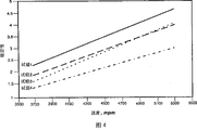
图4是处理速度相对于松弛辊上的纱线稳定性的关系曲线图。Figure 4 is a graph of process speed versus yarn stability on relax rolls.
具体实施方式Detailed ways
申请人已经申请了有关门式张力器及它们在纤维制造过程中在松弛区里使用的专利申请。本文引用DeBenedictis等人于2000年7月10日申请的美国S.N.09/613,225的内容。The applicant has filed a patent application concerning portal tensioners and their use in the slack zone in the fiber manufacturing process. US S.N. 09/613,225, filed July 10, 2000 by DeBenedictis et al. is cited herein.
本发明是空气屏蔽件和门式张力器装置的组合。诸如纺丝拉伸方法、拉伸加捻方法、拉伸络丝方法或拉伸膨化方法等现有方法包括松弛区,从而本发明的方法和装置能够用在这样的松弛区中。通过以上方法中的任何方法而被使用的任何熔纺聚合物,诸如聚酯、聚酰胺(尼龙),聚烯烃、聚酮、聚醚酮、聚苯硫醚以及多芳基化合物,可用于本发明。典型的聚酯是聚对苯二甲酸乙二酯、聚对苯二甲酸丁二酯、聚对苯二甲酸丙二酯、聚对苯二甲酸丙二醇酯、聚萘二甲酸乙二醇酯或者这些聚酯中任何聚酯的混合物,或者含有重量达到大约15%的聚烯烃、聚亚烷基二醇的这些聚酯的共聚物,或者诸如聚对苯二甲酸间苯二甲酸乙二醇酯之类的其它共聚多脂。典型的尼龙是尼龙6和尼龙66。典型的聚烯烃是聚乙烯、聚丙稀、聚丁烯或者它们的混合物。这些聚合物中的任何聚合物或者这些聚合物中任一种聚合物与其他诸如聚乙烯或聚丙稀等聚合物的以双组分纤维或异质复合丝纤维的形式形成的组合也在本发明的范围内。The present invention is a combination of an air shield and a door tensioner device. Existing methods such as spin-drawing methods, draw-twisting methods, draw-winding methods or draw-bulking methods include a relaxation zone so that the method and apparatus of the present invention can be used in such a relaxation zone. Any melt-spun polymer used by any of the above methods, such as polyesters, polyamides (nylons), polyolefins, polyketones, polyetherketones, polyphenylene sulfides, and polyarylates, can be used in this invention invention. Typical polyesters are polyethylene terephthalate, polybutylene terephthalate, polytrimethylene terephthalate, polytrimethylene terephthalate, polyethylene naphthalate or these Mixtures of any of polyesters, or copolymers of these polyesters containing up to about 15% by weight of polyolefins, polyalkylene glycols, or such polyesters as polyethylene terephthalate isophthalate Other copolyesters of the class. Typical nylons are nylon 6 and nylon 66. Typical polyolefins are polyethylene, polypropylene, polybutene or mixtures thereof. Any of these polymers or combinations of any of these polymers with other polymers such as polyethylene or polypropylene in the form of bicomponent fibers or heterogeneous composite filament fibers are also subject to the present invention. In the range.
当松弛程度增加时,在松弛区中的纱线张力减小,这样导致纱线在松弛区下游的辊子上变得不稳定。当处理速度增大时,由于作用在处于松弛辊上的纱线上的离心力增大,在恒定的松弛率下,稳定性变差。这样,当处理速度增大时,松弛程度必须减小以保持稳定性。由于低张力而移动或者摆动越过辊表面的纱线被定义为不稳定纱线。高度不稳定的纱线会使机械质量降低,在严重的情况下,会断开(纱线断丝)。As the degree of relaxation increases, the yarn tension in the relaxation zone decreases, which causes the yarn to become unstable on the rollers downstream of the relaxation zone. As the processing speed increases, the stability becomes poorer at a constant relaxation rate due to the increased centrifugal force acting on the yarn resting on the relaxation rollers. Thus, as processing speed increases, the degree of slack must decrease to maintain stability. Yarns that move or wobble across the roll surface due to low tension are defined as unstable yarns. Highly unstable yarns lead to reduced mechanical quality and, in severe cases, breakage (broken yarn).
当本发明的方法或者装置被用在具有松弛区的纱线制造方法中的任何方法中时,与传统的方法和装置相比,能获得较高程度的松弛以及由此产生的低热风收缩。在较高处理速度下通过使用本发明,与传统的低速条件相比,能够在高速条件下获得相同的松弛水平,或者能够保持处理速度而增加松弛水平,以便热风收缩能够被极大改善(即被降低),或者同时获得以上两者。When the method or apparatus of the present invention is used in any of the yarn manufacturing processes having a relaxation zone, a higher degree of relaxation and consequently lower through-air shrinkage can be achieved compared to conventional methods and apparatus. By using the present invention at higher processing speeds, the same level of relaxation can be achieved at high speeds compared to conventional low speed conditions, or the processing speed can be maintained while increasing the relaxation level so that hot air shrinkage can be greatly improved (i.e. be reduced), or both at the same time.
本发明的门式张力器将传统方法中的松弛区分隔成松弛区和小的拉伸区。不同的装置在设置于传统松弛区中时能产生分隔。可以利用空气阻力、液体阻力或者在固定表面上拉纱线而产生的阻力,对纱线施加阻力,从而生成门式张力器。通过使用例如一个或更多个混合件(intermingler)或者空气逆流装置(counter-current air-flow device),可以将空气阻力施加在纱线上。典型的是,用于空气阻力装置的空气压力是从5到50psi,更典型的是从10至40psi,并且优选在大约10至30psi。吹过纺丝的空气压力可直接与混合件设置在纺丝上的张力量相关。空气压力越高,张力越大。The portal tensioner of the present invention separates the relaxation zone in the conventional method into a relaxation zone and a small stretching zone. Different devices can create separation when placed in a traditional slack zone. A portal tensioner can be created by applying resistance to the yarn using air resistance, liquid resistance, or the resistance created by pulling the yarn on a fixed surface. Air resistance can be imposed on the yarn by using, for example, one or more interminglers or counter-current air-flow devices. Typically, the air pressure for the air resistance means is from 5 to 50 psi, more typically from 10 to 40 psi, and preferably about 10 to 30 psi. The air pressure blown through the spin can be directly related to the amount of tension the mixing element is placed on the spin. The higher the air pressure, the greater the tension.
例如,通过使用一个或更多个给油装置(给油装置是纺织工业中的技术人员所熟知的一种装置,它将涂饰剂或者涂料涂在纱线上)或者通过拉伸纱线使它经过液体池,可以引入液体阻力。典型地是,对应1000旦尼尔纱线,以大约4-7ml/分钟的速率涂液体。涂敷速率随着处理速度、旦尼尔量、所希望的张力以及本领域技术人员知试验的其他因素而变化。For example, by using one or more finishers (a finisher is a device well known to those skilled in the textile industry that applies a finish or paint to the yarn) or by stretching the yarn so that it Through the liquid pool, liquid resistance can be introduced. Typically, the liquid is applied at a rate of about 4-7 ml/minute for 1000 denier yarn. Coating rates will vary with process speed, denier, desired tension, and other factors known to those skilled in the art to experiment.
通过使纱线与一个或更多个固体表面(例如辊子)接触,可以引入固定表面阻力,其中纱线绕过或围绕着所述固体表面,然而因为纱线在辊上不具有多个卷,所以不存在纱线在门式张力器上来回移动或者摆动的问题,也不会引起纱线断损。在只希望获得越过一个或多个自由旋转辊(free-wheeling roll)的低张力梯度(例如5mg/d)的情况下,或者希望限制越过这种辊的张力梯度的情况下,有必要协助一个或更多个门式张力器辊的转动。换言之,因为总的转动阻力可能超过张力梯度,所以自由旋转辊具有充足的轴承摩擦和空气阻力,以致很难获得大约只有5mg/d的张力梯度。为了获得低的张力梯度,可以利用使用空气帮助驱动辊的涡轮驱动来帮助辊旋转。在本领域技术人员以及本发明的范围内,利用涡轮驱动或者诸如电动机等非常灵敏的二次辅助来操作辊是熟知的。Fixed surface resistance can be introduced by bringing the yarn into contact with one or more solid surfaces, such as rollers, over which the yarn passes or surrounds, however because the yarn does not have multiple turns on the rollers, So there is no problem of yarn moving or swinging back and forth on the portal tensioner, and there is no yarn breakage. In cases where only low tension gradients (e.g. 5mg/d) are desired across one or more free-wheeling rolls, or where it is desired to limit the tension gradient across such rolls, it is necessary to assist a or more rotations of the gate tensioner rolls. In other words, since the total rotational resistance may exceed the tension gradient, the freely rotating roll has sufficient bearing friction and air resistance so that it is difficult to obtain a tension gradient of only about 5 mg/d. To achieve low tension gradients, a turbine drive using air to help drive the rolls can be used to assist the roll rotation. Operating the rolls with turbine drives or very sensitive secondary assistance such as electric motors is well known to those skilled in the art and within the scope of the present invention.
门式张力器是这样一种装置:当用在纱线制造方法中的松弛区里时,它的出口纱线张力大于入口纱线张力,从而产生张力差。附加地,本发明的包括一个或更多个辊的门式张力器是非多卷纱线辊装置。张力差一般大于5毫克/旦尼尔(mg/d),这样如果纱线是1000旦尼尔纱线,那么本发明的门式张力器是5克,而如果纱线具有2000旦尼尔,那么门式张力器至少为10克。对于本发明,优选实施例是具有至少大约7mg/旦尼尔的张力差的门式张力器或者方法,更优选的是,大于大约9mg/d。本发明的门式张力器和方法在纱线制造系统的松弛区中的使用允许在相同的处理速度下具有较高的松弛程度以及相应的纱线热风收缩的显著降低。A gate tensioner is a device that, when used in the slack zone of a yarn manufacturing process, has an outlet yarn tension greater than an inlet yarn tension, thereby creating a tension differential. Additionally, the portal tensioner of the present invention comprising one or more rollers is a non-multi-roll yarn roller device. Tension differentials are generally greater than 5 milligrams per denier (mg/d), such that if the yarn is 1000 denier yarn, the gate tensioner of the present invention is 5 grams, and if the yarn has 2000 denier, Then the portal tensioner is at least 10 grams. For the present invention, a preferred embodiment is a portal tensioner or method having a tension differential of at least about 7 mg/denier, more preferably greater than about 9 mg/d. The use of the portal tensioner and method of the present invention in the relaxation zone of a yarn manufacturing system allows for a higher degree of relaxation at the same process speed and a corresponding significant reduction in yarn shrinkage through air.
如果我们假设,处理速度显著提高了10%,或者如果我们假设,松弛程度显著增加了15%,那么离开门式张力器的纱线与进入门式张力器的纱线之间的张力差为大约7mg/旦尼尔的门式张力器实现了显著的改进。这是优选实施例。当然,即使处理速度的提高小于10%和/或松弛程度的增加小于15%,也能获得好的稳定性。这种结果不以“显著改善”为特征,但也在本发明的范围内。If we assume, a significant 10% increase in processing speed, or if we assume, a significant 15% increase in slack, then the difference in tension between the yarn leaving the portal tensioner and the yarn entering the portal tensioner is approximately The 7mg/denier portal tensioner achieved a significant improvement. This is the preferred embodiment. Of course, good stability is obtained even with an increase in processing speed of less than 10% and/or an increase in relaxation of less than 15%. Such results are not characterized as "significantly improved", but are within the scope of the present invention.
图1示意性地示出包括门式张力器和空气屏蔽件的组合的本发明。参考图1,标号10在全文中表示位于纤维制造过程中的松弛区里的本发明的装置。松弛区具有一对间隔开的拉伸辊12、14,纤维纺丝16多重绕卷在拉伸辊12、14上。经过拉伸辊之后,纺丝16前进至门式张力器装置18,并且从门式张力器装置到达一对松弛辊20、22(这样辊20、22沿纺丝路径跟在门式张力器之后)。成对松弛辊具有在全文中用附图标记24示出的空气屏蔽件,所述空气屏蔽件安装在辊20、22附近并且与辊分离开大约1cm。如所述技术领域中已知的,屏蔽件24可以被穿孔或者为实心。空气屏蔽件24被支架(未示出)支撑,所述支架可以固定至辊20、22的支撑框(也未示出)上。空气屏蔽件位于纺丝16的内侧,以便阻止气流吹过纺丝并在辊20、22上产生运动。空气屏蔽件24包括至少一个板(薄并且为扁平形——大致呈两维),并且优选包括一对板26、28。所述板可以由任何能被打孔或为实心的材料制成,诸如:金属,例如铝或铜(实质上任何金属都能同样好地实现作用);塑料,例如聚碳酸酯、聚酯、聚酰胺等,这些材料在所述技术领域中是公知的;木材,橡胶;或者这些材料的组合。优选的是,间隔开的板26、28位于松弛辊20、22之间,并且在连接各个辊外表面的各个切线内,从而在纺丝16内。所述板阻止由于辊20、22的旋转而产生的空气流动,以及例如在生产设备中由风扇或送风机产生的任何空气流。依靠空气屏蔽件24距离辊20、22大约1cm并且离纺丝16有相同距离的事实,产生空气屏蔽件24附近的静止澄清区,从而显著地减少了由气流引起的、在辊20、22上的纺丝的运动带来的任何破坏。Figure 1 schematically shows the invention comprising a combination of a portal tensioner and an air shield. Referring to Figure 1, the numeral 10 indicates throughout the apparatus of the present invention in the relaxation zone of the fiber manufacturing process. The relaxation zone has a pair of spaced draw rolls 12, 14 upon which the spun
门式张力器装置18可以是发明人的现有专利申请中所讨论的任何装置,诸如一个或者更多个空气阻力装置、一个或更多个液体阻力装置、一个或更多个固体表面接触装置、或者这些装置中任何装置的两个或更多个的组合。关于图1,门式张力器装置包括一对辊30、32。离开门式张力器18的纱线所具有的张力大于进入门式张力器的纱线所具有的张力。The
在图1所述装置的操作中,例如来自拉伸阶段(未示出)的纺丝16多重地绕卷在成对辊12、14上。辊12、14的功能不是本发明的一部分,其依赖于存在有松弛区(松弛区包括辊12、14,门式张力器1 8以及辊20、22)的方法的类型。辊对12,14具有比辊对20,22快的处理速度(速率),从而在操作期间纱线松弛。因此,辊12、14可以是在纺丝拉伸方法中的一对拉伸辊,或者是在拉伸加捻方法中的一对辊,或者是在拉伸络丝方法中的一对辊,或者是在拉伸膨化方法中的一对辊。当离开成对辊12,14时,纺丝16进入门式张力器18。图1所示门式张力器包括一对辊30、32,与进入门式张力器的纺丝的张力相比,所述成对辊增大纺丝上的张力。然后,纺丝16前进至一对辊20、22,所述成对辊20、22例如可以是一对松弛辊。纺丝多重地绕卷在辊20、22上,并且离开所述辊进一步前进或者绕卷。在辊20、22附近是板26、28,纺丝16紧靠板的外侧表面通过。因为板26、28位于由纱线或者纤维16多重绕卷而产生的纺丝的内侧,如图3所示,所以空气屏蔽件24例如不会干扰装线(string-up)。门式张力器18利用辊30、32的旋转速度从门式张力器的入口至门式张力器的出口增加纺丝16上的张力。典型的是,在门式张力器中的第一辊30可以以小于辊12、14的速度旋转。门式张力器的第二辊32的旋转速度高于第一辊30的旋转速度,并且优选地是,与辊20、22的速度相同或者稍小于辊20、22的速度,从而保持围绕辊20、22的拉紧卷绕,由此增加在这些辊上的稳定性。In operation of the apparatus described in FIG. 1 , the spun
图2示出了本发明的第二变更实施方式,其中空气阻力装置或者液体阻力装置34结合门式张力器中的成对辊30、32而被使用。用于形成门式张力器装置18的该装置的组合公开在先前提到的申请人的专利申请中。图2所示装置的操作与图1所示装置的操作大致相类似,明显的区别在于:当离开辊12、14时纺丝16首先经过空气或者液体阻力装置34,然后绕在成对辊30、32上。气体或者液体阻力装置34将张力提供给来自例如位于辊12、14与门式张力器18之间的那部分松弛区的纺丝16。Figure 2 shows a second modified embodiment of the invention in which an air or
参考图3,示出了辊20、22的侧视图。位于辊20、22之间的是在纺丝内部的板28,从而允许观察者看见绕着辊20、22的纺丝卷,并且纺丝延伸到板28的外部(板28位于辊20、22的切线的内侧)。卷绕部分位于板28的外侧,从而板不与装置的装线(string-up)发生干扰。当从图3看时,纺丝16来自辊20右侧顶部上的门式张力器,卷绕辊20、22,并且从辊20左手侧顶部离开,以便进一步处理或缠绕。Referring to FIG. 3 , a side view of the
辊对12、14和20、22可以具有相同或不同的尺寸。附加地,成对的辊12、14或者成对的辊20、22也不需要具有相同尺寸。例如,辊12可以是从动辊,辊14可以是较小的分离辊,类似地,辊20可以是从动辊,辊22可以是较小的分离辊。The roller pairs 12, 14 and 20, 22 may be of the same or different dimensions. Additionally, the pair of
例子example
在传统纺丝拉伸方法中,聚酯聚合物通过喷丝头被挤出,然后被纺制、拉伸和松弛。纺成的纱线的特性粘度(IV)是0.88(25℃下在邻氯苯酚中测得)。In traditional spin-drawing methods, polyester polymer is extruded through a spinneret, then spun, drawn and relaxed. The intrinsic viscosity (IV) of the spun yarn was 0.88 (measured in o-chlorophenol at 25°C).
纺成的纱线在两级过程中被拉伸。最终的拉伸辊具有242℃的温度。在240℃的温度下,纱线在这些拉伸辊与成对松弛辊之间被松弛9.62%。The spun yarn is stretched in a two-stage process. The final draw rolls had a temperature of 242°C. At a temperature of 240°C, the yarn was relaxed by 9.62% between these draw rolls and the pair of relaxation rolls.
初始条件是678mpm的纺丝速度、3658mpm的最终拉伸速度。最终拉伸速度以250mpm的增量增加,以生成图4所示的线,同时纺丝速度也增加,以保持恒定的纱线物理属性(韧性和伸长率)。生产量被调整(增加),以保持1000的最终拉伸旦尼尔。在松弛辊上的绕线的纱线稳定性被记录作为拉伸辊速度的函数。Initial conditions were a spinning speed of 678 mpm, a final drawing speed of 3658 mpm. The final drawing speed was increased in 250 mpm increments to produce the yarn shown in Figure 4, while the spinning speed was also increased to maintain constant yarn physical properties (tenacity and elongation). The throughput was adjusted (increased) to maintain a final stretch denier of 1000. The yarn stability of the winding on the relaxation roll was recorded as a function of the draw roll speed.
主观标尺(subjective scale)用于定义纱线稳定性。等级1(优秀)被定义为非常稳定,没有纺丝移动或者摆动,等级5(极差)被定义为足以使纺丝立即断损的纱线移动。等级3.0至3.5被认为是制造过程中所允许的非稳定性的最大程度。优选可接收的稳定性是从1.0至2.5。A subjective scale is used to define yarn stability. A rating of 1 (excellent) is defined as very stable with no spin movement or wobbling and a rating of 5 (extremely poor) is defined as sufficient yarn movement to cause an immediate spin break. A rating of 3.0 to 3.5 is considered the maximum degree of instability allowed in the manufacturing process. A preferred acceptable stability is from 1.0 to 2.5.
例子1Example 1
试验(run)1在松弛辊(控制)之间没有门式张力器或者空气吹提器(air stripper)。
试验2具有门式张力器,所述门式张力器包括2两个空气从动辊,如图1所示。在第一辊上的断损角是161度,第二辊上的断损角是175度。这样产生55-70克的门式张力器。
试验3在成对松弛辊之间使用空气吹提器板,并且距离所述辊大约1cm。
试验4结合了试验2的门式张力器和试验3的空气吹提器板。
图4示出了跟随门式张力器的第一组辊上的纱线稳定性,其中所述纱线稳定性作为这些试验的拉伸速度的函数。特别地,在紧靠门式张力器之前的拉伸辊上进行拉伸速度的测量,以米/分钟(mpm)进行测量。从该图中,对应第3等级纱线稳定性的处理速度示出在表1中。Figure 4 shows the yarn stability on the first set of rollers following the portal tensioner as a function of the stretching speed for these tests. In particular, the measurement of the drawing speed, measured in meters per minute (mpm), was performed on the drawing rolls immediately preceding the portal tensioner. From this figure, the processing speeds corresponding to
表1
以往认为,组合不会产生比单独使用空气屏蔽件或者单独使用门式张力器明显更好的结果,因为一旦松弛辊上的纱线稳定了,最多只能期望较小的改进。所能期望的最好的情况是门式张力器和空气吹提器的组合产生加和效果,即620mpm的速度增量,同时保持3的稳定性等级。但令人惊讶的是,速度增量在1,100mpm,提高了60%,从而显示了增效效果。It was previously thought that the combination would not produce significantly better results than either the air shield or the gate tensioner alone, as at best only minor improvements could be expected once the yarn on the relax roll had stabilized. The best that can be hoped for is that the combination of the portal tensioner and the air stripper produces an additive effect, a speed increment of 620 mpm, while maintaining a stability rating of 3. But surprisingly, the speed increment is 60% higher at 1,100mpm, thus showing the synergistic effect.
例2Example 2
使用例1、试验4的构造,在两个辊门式张力器之前添加附加的门式张力器,如图2所示。这种门式张力器是在30psig的压力下工作的空气混合件(air intermingler)。使用5000mpm的拉伸速度,150℃温度下在松弛辊上的松弛率是8.91%(拉伸辊保持在242℃下)。Using the configuration of Example 1,
在5,000mpm下,当空气供至混合件时,纺丝稳定性从3.0改进至2.75。At 5,000 mpm, the spinning stability improved from 3.0 to 2.75 when air was supplied to the mixing element.
从而可以了解,根据本发明已经提供了一种能够完全满足上述目的、目标和优点的方法和装置。尽管已经结合本发明的特定实施例描述了本发明,但显然根据以上的描述,许多可选实施方式、变更实施方式和变化实施方式对于本领域技术人员是显而易见的。由此,本发明旨在将所有这些可选实施方式、变更实施方式以及变化实施方式涵盖在权利要求的实质和广泛的范围内。It will thus be appreciated that in accordance with the present invention there has been provided a method and apparatus which fully satisfy the above objects, objects and advantages. While the invention has been described in conjunction with specific embodiments thereof, it is evident from the foregoing description that many alternatives, modifications and variations will be apparent to those skilled in the art. Accordingly, the present invention intends to cover all such alternatives, modifications, and variations within the true and broad scope of the claims.
Claims (29)
Applications Claiming Priority (1)
| Application Number | Priority Date | Filing Date | Title |
|---|---|---|---|
| PCT/US2002/000153 WO2003060205A1 (en) | 2002-01-03 | 2002-01-03 | Yarn making process and apparatus |
Publications (2)
| Publication Number | Publication Date |
|---|---|
| CN1610770A CN1610770A (en) | 2005-04-27 |
| CN100347350C true CN100347350C (en) | 2007-11-07 |
Family
ID=21743192
Family Applications (1)
| Application Number | Title | Priority Date | Filing Date |
|---|---|---|---|
| CNB028266048A Expired - Fee Related CN100347350C (en) | 2002-01-03 | 2002-01-03 | Method for producing yarn and apparatus thereof |
Country Status (8)
| Country | Link |
|---|---|
| EP (1) | EP1463852B1 (en) |
| KR (1) | KR100624573B1 (en) |
| CN (1) | CN100347350C (en) |
| AU (1) | AU2002235295A1 (en) |
| CA (1) | CA2469220A1 (en) |
| DE (1) | DE60225477T2 (en) |
| MX (1) | MXPA04006527A (en) |
| WO (1) | WO2003060205A1 (en) |
Cited By (1)
| Publication number | Priority date | Publication date | Assignee | Title |
|---|---|---|---|---|
| CN102912464A (en) * | 2012-11-13 | 2013-02-06 | 南通芯迎设计服务有限公司 | Thermoplastic material spinning equipment |
Families Citing this family (6)
| Publication number | Priority date | Publication date | Assignee | Title |
|---|---|---|---|---|
| EP1778898A4 (en) * | 2004-07-30 | 2008-05-28 | Invista Tech Sarl | VARIABLE AIR SHIELD FOR CYCLES |
| CN1319978C (en) * | 2005-04-06 | 2007-06-06 | 西南合成制药股份有限公司 | Combretastatin compound preparation method |
| CN102373525B (en) * | 2010-08-06 | 2015-10-07 | 日本Tmt机械株式会社 | Yarn heating apparatus |
| WO2015185245A1 (en) * | 2014-06-07 | 2015-12-10 | Oerlikon Textile Gmbh & Co. Kg | Method and device for drawing off and drawing a plurality of freshly spun fibres |
| DE102014012145A1 (en) | 2014-08-14 | 2016-03-03 | Oerlikon Textile Gmbh & Co. Kg | Apparatus for stripping and drawing a plurality of threads |
| JP6446292B2 (en) * | 2015-03-06 | 2018-12-26 | Tmtマシナリー株式会社 | Spinning and drawing equipment |
Citations (2)
| Publication number | Priority date | Publication date | Assignee | Title |
|---|---|---|---|---|
| JPS5826767A (en) * | 1981-08-06 | 1983-02-17 | Toray Ind Inc | Method for preventing yarn from vibrating in high-speed winding of yarn |
| US5240667A (en) * | 1991-11-13 | 1993-08-31 | E. I. Du Pont De Nemours And Company | Process of making high strength, low shrinkage polyamide yarn |
-
2002
- 2002-01-03 AU AU2002235295A patent/AU2002235295A1/en not_active Abandoned
- 2002-01-03 CA CA002469220A patent/CA2469220A1/en not_active Abandoned
- 2002-01-03 KR KR1020047010485A patent/KR100624573B1/en not_active Expired - Fee Related
- 2002-01-03 DE DE60225477T patent/DE60225477T2/en not_active Expired - Fee Related
- 2002-01-03 MX MXPA04006527A patent/MXPA04006527A/en not_active Application Discontinuation
- 2002-01-03 EP EP02701893A patent/EP1463852B1/en not_active Expired - Lifetime
- 2002-01-03 CN CNB028266048A patent/CN100347350C/en not_active Expired - Fee Related
- 2002-01-03 WO PCT/US2002/000153 patent/WO2003060205A1/en not_active Ceased
Patent Citations (2)
| Publication number | Priority date | Publication date | Assignee | Title |
|---|---|---|---|---|
| JPS5826767A (en) * | 1981-08-06 | 1983-02-17 | Toray Ind Inc | Method for preventing yarn from vibrating in high-speed winding of yarn |
| US5240667A (en) * | 1991-11-13 | 1993-08-31 | E. I. Du Pont De Nemours And Company | Process of making high strength, low shrinkage polyamide yarn |
Cited By (2)
| Publication number | Priority date | Publication date | Assignee | Title |
|---|---|---|---|---|
| CN102912464A (en) * | 2012-11-13 | 2013-02-06 | 南通芯迎设计服务有限公司 | Thermoplastic material spinning equipment |
| CN102912464B (en) * | 2012-11-13 | 2016-08-24 | 广州市新辉联无纺布有限公司 | A kind of thermoplastic spinning equipment |
Also Published As
| Publication number | Publication date |
|---|---|
| KR20040078119A (en) | 2004-09-08 |
| EP1463852B1 (en) | 2008-03-05 |
| MXPA04006527A (en) | 2005-03-31 |
| EP1463852A1 (en) | 2004-10-06 |
| WO2003060205A1 (en) | 2003-07-24 |
| KR100624573B1 (en) | 2006-09-19 |
| EP1463852A4 (en) | 2005-10-12 |
| CN1610770A (en) | 2005-04-27 |
| DE60225477T2 (en) | 2009-03-26 |
| DE60225477D1 (en) | 2008-04-17 |
| CA2469220A1 (en) | 2003-07-24 |
| AU2002235295A1 (en) | 2003-07-30 |
Similar Documents
| Publication | Publication Date | Title |
|---|---|---|
| CN1263903C (en) | Method and device for filament spinning, drawing and winding | |
| US9080258B2 (en) | Process of making highly oriented and crystalline thermoplastic filaments | |
| EP0438421A1 (en) | Improved process for high speed, multi-end polyester high performance tire and industrial yarn. | |
| CN1006471B (en) | A method and device for fiber spinning | |
| CN100347350C (en) | Method for producing yarn and apparatus thereof | |
| CN1238579C (en) | Spin draw process of making partially orientated yarns from polytrimethylene terephthalate | |
| US3936253A (en) | Apparatus for melt-spinning synthetic fibers | |
| CN104903501B (en) | Stretching device and drawing process | |
| US4045534A (en) | Process for melt-spinning synthetic fibers | |
| CN1304651C (en) | Ultra-low tension letdown method and tension brake apparatus | |
| CN100445435C (en) | Synthetic fiber manufacturing method and manufacturing device | |
| CN1268532C (en) | Method of winding monofilament | |
| US20050029700A1 (en) | Yarn making process and apparatus | |
| US7273578B1 (en) | Method and apparatus for low-speed, high-throughput fiber drawing using coiled fiber loops | |
| US3756006A (en) | False-twist arrangement | |
| US3123891A (en) | Apparatus for drawing textile filaments | |
| CN101001983A (en) | Adjustable air shield for skewed godet rolls | |
| KR100232726B1 (en) | Process for preparing different shrinkage blended yarn | |
| JP2906678B2 (en) | Direct spinning and drawing method for synthetic fibers | |
| KR100211134B1 (en) | Method for producing polyester fiber | |
| JP4563849B2 (en) | Synthetic fiber spinning direct drawing apparatus and method | |
| CN1155303A (en) | Process for preparing polybenzoxazole filaments and fibers | |
| JPH09228137A (en) | High-definition high multifilament yarn manufacturing equipment | |
| CN1238815A (en) | Process and device for producing industrial polyester yarn | |
| JPH10273842A (en) | Winding method for undrawn yarn |
Legal Events
| Date | Code | Title | Description |
|---|---|---|---|
| C06 | Publication | ||
| PB01 | Publication | ||
| C10 | Entry into substantive examination | ||
| SE01 | Entry into force of request for substantive examination | ||
| C14 | Grant of patent or utility model | ||
| GR01 | Patent grant | ||
| C19 | Lapse of patent right due to non-payment of the annual fee | ||
| CF01 | Termination of patent right due to non-payment of annual fee |