CN100354103C - Bellows manufacturing method and device - Google Patents
Bellows manufacturing method and device Download PDFInfo
- Publication number
- CN100354103C CN100354103C CNB028250281A CN02825028A CN100354103C CN 100354103 C CN100354103 C CN 100354103C CN B028250281 A CNB028250281 A CN B028250281A CN 02825028 A CN02825028 A CN 02825028A CN 100354103 C CN100354103 C CN 100354103C
- Authority
- CN
- China
- Prior art keywords
- module
- row
- unit
- unit modules
- bellows
- Prior art date
- Legal status (The legal status is an assumption and is not a legal conclusion. Google has not performed a legal analysis and makes no representation as to the accuracy of the status listed.)
- Expired - Fee Related
Links
Images


Classifications
-
- B—PERFORMING OPERATIONS; TRANSPORTING
- B29—WORKING OF PLASTICS; WORKING OF SUBSTANCES IN A PLASTIC STATE IN GENERAL
- B29C—SHAPING OR JOINING OF PLASTICS; SHAPING OF MATERIAL IN A PLASTIC STATE, NOT OTHERWISE PROVIDED FOR; AFTER-TREATMENT OF THE SHAPED PRODUCTS, e.g. REPAIRING
- B29C49/00—Blow-moulding, i.e. blowing a preform or parison to a desired shape within a mould; Apparatus therefor
- B29C49/0015—Making articles of indefinite length, e.g. corrugated tubes
- B29C49/0021—Making articles of indefinite length, e.g. corrugated tubes using moulds or mould parts movable in a closed path, e.g. mounted on movable endless supports
- B29C49/0022—Making articles of indefinite length, e.g. corrugated tubes using moulds or mould parts movable in a closed path, e.g. mounted on movable endless supports characterised by mould return means
-
- B—PERFORMING OPERATIONS; TRANSPORTING
- B29—WORKING OF PLASTICS; WORKING OF SUBSTANCES IN A PLASTIC STATE IN GENERAL
- B29C—SHAPING OR JOINING OF PLASTICS; SHAPING OF MATERIAL IN A PLASTIC STATE, NOT OTHERWISE PROVIDED FOR; AFTER-TREATMENT OF THE SHAPED PRODUCTS, e.g. REPAIRING
- B29C48/00—Extrusion moulding, i.e. expressing the moulding material through a die or nozzle which imparts the desired form; Apparatus therefor
- B29C48/03—Extrusion moulding, i.e. expressing the moulding material through a die or nozzle which imparts the desired form; Apparatus therefor characterised by the shape of the extruded material at extrusion
- B29C48/09—Articles with cross-sections having partially or fully enclosed cavities, e.g. pipes or channels
-
- B—PERFORMING OPERATIONS; TRANSPORTING
- B29—WORKING OF PLASTICS; WORKING OF SUBSTANCES IN A PLASTIC STATE IN GENERAL
- B29C—SHAPING OR JOINING OF PLASTICS; SHAPING OF MATERIAL IN A PLASTIC STATE, NOT OTHERWISE PROVIDED FOR; AFTER-TREATMENT OF THE SHAPED PRODUCTS, e.g. REPAIRING
- B29C48/00—Extrusion moulding, i.e. expressing the moulding material through a die or nozzle which imparts the desired form; Apparatus therefor
- B29C48/03—Extrusion moulding, i.e. expressing the moulding material through a die or nozzle which imparts the desired form; Apparatus therefor characterised by the shape of the extruded material at extrusion
- B29C48/13—Articles with a cross-section varying in the longitudinal direction, e.g. corrugated pipes
-
- B—PERFORMING OPERATIONS; TRANSPORTING
- B29—WORKING OF PLASTICS; WORKING OF SUBSTANCES IN A PLASTIC STATE IN GENERAL
- B29C—SHAPING OR JOINING OF PLASTICS; SHAPING OF MATERIAL IN A PLASTIC STATE, NOT OTHERWISE PROVIDED FOR; AFTER-TREATMENT OF THE SHAPED PRODUCTS, e.g. REPAIRING
- B29C48/00—Extrusion moulding, i.e. expressing the moulding material through a die or nozzle which imparts the desired form; Apparatus therefor
- B29C48/25—Component parts, details or accessories; Auxiliary operations
- B29C48/30—Extrusion nozzles or dies
- B29C48/303—Extrusion nozzles or dies using dies or die parts movable in a closed circuit, e.g. mounted on movable endless support
-
- B—PERFORMING OPERATIONS; TRANSPORTING
- B29—WORKING OF PLASTICS; WORKING OF SUBSTANCES IN A PLASTIC STATE IN GENERAL
- B29C—SHAPING OR JOINING OF PLASTICS; SHAPING OF MATERIAL IN A PLASTIC STATE, NOT OTHERWISE PROVIDED FOR; AFTER-TREATMENT OF THE SHAPED PRODUCTS, e.g. REPAIRING
- B29C48/00—Extrusion moulding, i.e. expressing the moulding material through a die or nozzle which imparts the desired form; Apparatus therefor
- B29C48/25—Component parts, details or accessories; Auxiliary operations
- B29C48/92—Measuring, controlling or regulating
-
- B—PERFORMING OPERATIONS; TRANSPORTING
- B29—WORKING OF PLASTICS; WORKING OF SUBSTANCES IN A PLASTIC STATE IN GENERAL
- B29C—SHAPING OR JOINING OF PLASTICS; SHAPING OF MATERIAL IN A PLASTIC STATE, NOT OTHERWISE PROVIDED FOR; AFTER-TREATMENT OF THE SHAPED PRODUCTS, e.g. REPAIRING
- B29C49/00—Blow-moulding, i.e. blowing a preform or parison to a desired shape within a mould; Apparatus therefor
- B29C49/02—Combined blow-moulding and manufacture of the preform or the parison
- B29C49/04—Extrusion blow-moulding
-
- B—PERFORMING OPERATIONS; TRANSPORTING
- B29—WORKING OF PLASTICS; WORKING OF SUBSTANCES IN A PLASTIC STATE IN GENERAL
- B29C—SHAPING OR JOINING OF PLASTICS; SHAPING OF MATERIAL IN A PLASTIC STATE, NOT OTHERWISE PROVIDED FOR; AFTER-TREATMENT OF THE SHAPED PRODUCTS, e.g. REPAIRING
- B29C49/00—Blow-moulding, i.e. blowing a preform or parison to a desired shape within a mould; Apparatus therefor
- B29C49/42—Component parts, details or accessories; Auxiliary operations
- B29C49/78—Measuring, controlling or regulating
-
- B—PERFORMING OPERATIONS; TRANSPORTING
- B29—WORKING OF PLASTICS; WORKING OF SUBSTANCES IN A PLASTIC STATE IN GENERAL
- B29C—SHAPING OR JOINING OF PLASTICS; SHAPING OF MATERIAL IN A PLASTIC STATE, NOT OTHERWISE PROVIDED FOR; AFTER-TREATMENT OF THE SHAPED PRODUCTS, e.g. REPAIRING
- B29C2791/00—Shaping characteristics in general
- B29C2791/001—Shaping in several steps
-
- B—PERFORMING OPERATIONS; TRANSPORTING
- B29—WORKING OF PLASTICS; WORKING OF SUBSTANCES IN A PLASTIC STATE IN GENERAL
- B29C—SHAPING OR JOINING OF PLASTICS; SHAPING OF MATERIAL IN A PLASTIC STATE, NOT OTHERWISE PROVIDED FOR; AFTER-TREATMENT OF THE SHAPED PRODUCTS, e.g. REPAIRING
- B29C2791/00—Shaping characteristics in general
- B29C2791/004—Shaping under special conditions
- B29C2791/006—Using vacuum
-
- B—PERFORMING OPERATIONS; TRANSPORTING
- B29—WORKING OF PLASTICS; WORKING OF SUBSTANCES IN A PLASTIC STATE IN GENERAL
- B29C—SHAPING OR JOINING OF PLASTICS; SHAPING OF MATERIAL IN A PLASTIC STATE, NOT OTHERWISE PROVIDED FOR; AFTER-TREATMENT OF THE SHAPED PRODUCTS, e.g. REPAIRING
- B29C2791/00—Shaping characteristics in general
- B29C2791/004—Shaping under special conditions
- B29C2791/007—Using fluid under pressure
-
- B—PERFORMING OPERATIONS; TRANSPORTING
- B29—WORKING OF PLASTICS; WORKING OF SUBSTANCES IN A PLASTIC STATE IN GENERAL
- B29C—SHAPING OR JOINING OF PLASTICS; SHAPING OF MATERIAL IN A PLASTIC STATE, NOT OTHERWISE PROVIDED FOR; AFTER-TREATMENT OF THE SHAPED PRODUCTS, e.g. REPAIRING
- B29C2948/00—Indexing scheme relating to extrusion moulding
- B29C2948/92—Measuring, controlling or regulating
- B29C2948/92504—Controlled parameter
- B29C2948/9258—Velocity
-
- B—PERFORMING OPERATIONS; TRANSPORTING
- B29—WORKING OF PLASTICS; WORKING OF SUBSTANCES IN A PLASTIC STATE IN GENERAL
- B29C—SHAPING OR JOINING OF PLASTICS; SHAPING OF MATERIAL IN A PLASTIC STATE, NOT OTHERWISE PROVIDED FOR; AFTER-TREATMENT OF THE SHAPED PRODUCTS, e.g. REPAIRING
- B29C2948/00—Indexing scheme relating to extrusion moulding
- B29C2948/92—Measuring, controlling or regulating
- B29C2948/92504—Controlled parameter
- B29C2948/92609—Dimensions
-
- B—PERFORMING OPERATIONS; TRANSPORTING
- B29—WORKING OF PLASTICS; WORKING OF SUBSTANCES IN A PLASTIC STATE IN GENERAL
- B29C—SHAPING OR JOINING OF PLASTICS; SHAPING OF MATERIAL IN A PLASTIC STATE, NOT OTHERWISE PROVIDED FOR; AFTER-TREATMENT OF THE SHAPED PRODUCTS, e.g. REPAIRING
- B29C2948/00—Indexing scheme relating to extrusion moulding
- B29C2948/92—Measuring, controlling or regulating
- B29C2948/92819—Location or phase of control
- B29C2948/92933—Conveying, transporting or storage of articles
-
- B—PERFORMING OPERATIONS; TRANSPORTING
- B29—WORKING OF PLASTICS; WORKING OF SUBSTANCES IN A PLASTIC STATE IN GENERAL
- B29C—SHAPING OR JOINING OF PLASTICS; SHAPING OF MATERIAL IN A PLASTIC STATE, NOT OTHERWISE PROVIDED FOR; AFTER-TREATMENT OF THE SHAPED PRODUCTS, e.g. REPAIRING
- B29C33/00—Moulds or cores; Details thereof or accessories therefor
- B29C33/30—Mounting, exchanging or centering
- B29C33/308—Adjustable moulds
-
- B—PERFORMING OPERATIONS; TRANSPORTING
- B29—WORKING OF PLASTICS; WORKING OF SUBSTANCES IN A PLASTIC STATE IN GENERAL
- B29C—SHAPING OR JOINING OF PLASTICS; SHAPING OF MATERIAL IN A PLASTIC STATE, NOT OTHERWISE PROVIDED FOR; AFTER-TREATMENT OF THE SHAPED PRODUCTS, e.g. REPAIRING
- B29C48/00—Extrusion moulding, i.e. expressing the moulding material through a die or nozzle which imparts the desired form; Apparatus therefor
- B29C48/001—Combinations of extrusion moulding with other shaping operations
-
- B—PERFORMING OPERATIONS; TRANSPORTING
- B29—WORKING OF PLASTICS; WORKING OF SUBSTANCES IN A PLASTIC STATE IN GENERAL
- B29C—SHAPING OR JOINING OF PLASTICS; SHAPING OF MATERIAL IN A PLASTIC STATE, NOT OTHERWISE PROVIDED FOR; AFTER-TREATMENT OF THE SHAPED PRODUCTS, e.g. REPAIRING
- B29C49/00—Blow-moulding, i.e. blowing a preform or parison to a desired shape within a mould; Apparatus therefor
- B29C49/0015—Making articles of indefinite length, e.g. corrugated tubes
- B29C49/0025—Making articles of indefinite length, e.g. corrugated tubes subsequent mould cavities being different, e.g. for making bells
-
- B—PERFORMING OPERATIONS; TRANSPORTING
- B29—WORKING OF PLASTICS; WORKING OF SUBSTANCES IN A PLASTIC STATE IN GENERAL
- B29C—SHAPING OR JOINING OF PLASTICS; SHAPING OF MATERIAL IN A PLASTIC STATE, NOT OTHERWISE PROVIDED FOR; AFTER-TREATMENT OF THE SHAPED PRODUCTS, e.g. REPAIRING
- B29C49/00—Blow-moulding, i.e. blowing a preform or parison to a desired shape within a mould; Apparatus therefor
- B29C49/0015—Making articles of indefinite length, e.g. corrugated tubes
- B29C49/0027—Making articles of indefinite length, e.g. corrugated tubes involving the change of moulds, e.g. in production processes without interrupting the production processes
-
- B—PERFORMING OPERATIONS; TRANSPORTING
- B29—WORKING OF PLASTICS; WORKING OF SUBSTANCES IN A PLASTIC STATE IN GENERAL
- B29K—INDEXING SCHEME ASSOCIATED WITH SUBCLASSES B29B, B29C OR B29D, RELATING TO MOULDING MATERIALS OR TO MATERIALS FOR MOULDS, REINFORCEMENTS, FILLERS OR PREFORMED PARTS, e.g. INSERTS
- B29K2021/00—Use of unspecified rubbers as moulding material
-
- B—PERFORMING OPERATIONS; TRANSPORTING
- B29—WORKING OF PLASTICS; WORKING OF SUBSTANCES IN A PLASTIC STATE IN GENERAL
- B29L—INDEXING SCHEME ASSOCIATED WITH SUBCLASS B29C, RELATING TO PARTICULAR ARTICLES
- B29L2016/00—Articles with corrugations or pleats
-
- B—PERFORMING OPERATIONS; TRANSPORTING
- B29—WORKING OF PLASTICS; WORKING OF SUBSTANCES IN A PLASTIC STATE IN GENERAL
- B29L—INDEXING SCHEME ASSOCIATED WITH SUBCLASS B29C, RELATING TO PARTICULAR ARTICLES
- B29L2023/00—Tubular articles
- B29L2023/18—Pleated or corrugated hoses
-
- B—PERFORMING OPERATIONS; TRANSPORTING
- B29—WORKING OF PLASTICS; WORKING OF SUBSTANCES IN A PLASTIC STATE IN GENERAL
- B29L—INDEXING SCHEME ASSOCIATED WITH SUBCLASS B29C, RELATING TO PARTICULAR ARTICLES
- B29L2023/00—Tubular articles
- B29L2023/18—Pleated or corrugated hoses
- B29L2023/183—Pleated or corrugated hoses partially
Landscapes
- Engineering & Computer Science (AREA)
- Mechanical Engineering (AREA)
- Manufacturing & Machinery (AREA)
- Extrusion Moulding Of Plastics Or The Like (AREA)
- Moulds For Moulding Plastics Or The Like (AREA)
- Blow-Moulding Or Thermoforming Of Plastics Or The Like (AREA)
Abstract
能够不进行改装工作而改变随着波纹管规格的改变而改变的模块的排列样式,在机械设备不停止工作的情况下,任意改变模块的排列样式后送入成形区,提高了波纹管的生产率。根据对形成与波纹管的形状相对应的第1模块列(20)以及第2模块列(22)的、每一种单位模块MBa、MBb、MBc、MBd的数量以及顺序进行指定的队列编组,选择所需要的单位模块编组成第1模块列(20、22)向成形区(24)移送,从挤出机(26)的挤出模(25)向第1模块列(20)和第2模块列(22)之间挤出熔融树脂,使得在第1模块列(20)和第2模块列(22)在向同方向移动的同时进行合模而成的模具的内部产生负压从而形成波纹管,从成形区返回的各模块列被分往其单位模块按类别的排列中。
The module arrangement can be changed without modification to accommodate changes in the bellows specifications. The module arrangement can be changed arbitrarily before being fed into the forming area without stopping the machinery, thus improving the bellows production rate. Based on the number and order of each unit module MBa, MBb, MBc, MBd in the first module column (20) and the second module column (22) corresponding to the shape of the bellows, the required unit modules are selected and arranged into the first module column (20, 22) and transferred to the forming area (24). Molten resin is extruded from the extrusion die (25) of the extruder (26) between the first module column (20) and the second module column (22), so that a negative pressure is generated inside the mold formed by the mold closing while the first module column (20) and the second module column (22) move in the same direction, thereby forming the bellows. The module columns returning from the forming area are assigned to their respective unit modules according to their categories.
Description
技术领域technical field
本发明涉及可用作汽车等的燃料配管和油气配管的树脂制造波纹管的制造方法以及装置。The present invention relates to a method and an apparatus for manufacturing a resin-made corrugated pipe that can be used as fuel pipes and oil-gas pipes for automobiles and the like.
背景技术Background technique
图5示出树脂制造的波纹管。树脂制造的波纹管2,由于管子本身具有很好的强度、耐腐蚀性而且易于弯曲,因此,作为组装在汽车车体的狭小空间内的燃料配管等而得到广泛应用。这种波纹管2,通常是将由波纹状管体构成的波纹部3、以及、为了安装管接头5而由直管形管体构成的直管部4做成一体而构成。在整理配管时有时需要将波纹管3用夹子等进行固定,因而有的波纹管在波纹部3的中间形成有直管部4。Fig. 5 shows a bellows made of resin. The
如图6所示,作为构成波纹管2的形状要素,较典型的有:波纹形状要素A(图6(a))、直管形状要素B(图6(b))、波纹部的端部为直管部的形状要素C(图6(c))、以及、直管部的两端为波纹部的形状要素D(图6(d))等。具有各种波纹样式的波纹管无论长短,均是由这些形状要素组合而成的。As shown in Fig. 6, as the shape elements constituting the
过去,波纹管2,是将对应于上述形状要素的模块进行组合而构成模具,采用向该模具内挤出作为材料的树脂的挤出成形方式进行制造的。Conventionally, the
图7示出制造波纹管2的现有的挤出成形方法。作为与此有关的现有技术的典型例子,特表平7-520815(对应于USP5460771号)号公报所公开的现有技术已经公知。FIG. 7 shows a conventional extrusion molding method for manufacturing the
图7中,参考编号10是下模块,12是上模块。下模块10和上模块12各自具有半圆筒形的成形面,它们是例如安装在构成循环移送装置的链条或皮带上,以无接头方式相连的,当在成形区中移动时,下模块10和上模块12在合模状态下作直线移动。14是对由未图示的挤出机供给的熔融树脂进行挤出的挤出模。该挤出模14,配置在成形区的入口处,将熔融树脂挤出到处于从打开状态即将闭合的状态的下模块10和上模块12之间。In FIG. 7,
在成形区中,进行抽真空以分别在下模块10和上模块12的成形面上产生负压,使得被挤出出来的熔融树脂紧密贴合在成形面上而成形为凹凸部连续的波纹管状,在移动到成形区的下游时,下模块10和上模块12打开,使成形的管子脱模。In the forming area, vacuuming is carried out to generate negative pressure on the forming surfaces of the
以现有的挤出成形方法制造波纹管时,需要根据成品的波纹样式,预先如图7所示进行具有所设定形状要素的单位模块的组合。这些单位模块,以相同的排列样式呈环形连接而分别形成下模块10和上模块12。When corrugated pipes are produced by the conventional extrusion molding method, it is necessary to combine unit modules having predetermined shape elements in advance as shown in FIG. 7 according to the corrugation pattern of the finished product. These unit modules are ring-connected in the same arrangement pattern to form the
过去,在改变作为制造对象的波纹管的规格时,必须进行改装工作,按照波纹样式改变单位模块的排列。在该改装工作中,由于单位模块的排列要因波纹样式的改变而改变,因此,要进行,反复拆卸和安装单位模块、按照新的波纹样式进行排列而重新组合成环形,这种作业繁杂而劳动强度很大,为了进行该改装工作,要使挤出成形机停止工作,这一段时间便成了空置时间。而且,在停止工作期间,多会发生树脂在挤出成形机的挤出筒和挤出模的内部滞留、老化的情况。为此,在将单位模块的排列改为新的样式后开始进行管子的成形时,必须将滞留和老化的的树脂去除,不仅造成树脂材料的浪费,而且要占用时间进行该作业,影响生产率的提高。In the past, when changing the specifications of corrugated pipes to be manufactured, it was necessary to carry out refitting work to change the arrangement of unit modules according to the corrugated pattern. In this refitting work, since the arrangement of the unit modules will be changed due to the change of the corrugation pattern, it is necessary to repeatedly disassemble and install the unit modules, arrange them according to the new corrugation pattern and recombine them into a ring, which is complicated and laborious. The strength is very high. In order to carry out the conversion work, the extrusion molding machine must be stopped, and this period of time becomes an idle time. Furthermore, resin stagnation and aging in the extrusion barrel and extrusion die of the extrusion molding machine often occur during shutdown. For this reason, when starting to form the pipe after changing the arrangement of the unit modules to a new pattern, it is necessary to remove the stagnant and aged resin, which not only causes waste of resin material, but also takes time for this operation, which affects productivity. improve.
发明的公开disclosure of invention
因此,本发明的目的是,解决上述现有技术存在的问题,提供这样一种波纹管制造方法以及装置,即,能够不进行改装工作而随着波纹管规格的改变而改变的模块的排列样式,能够任意改组模块的排列样式,在机械设备不停止工作的情况下,自由地高效率地制造各种规格的波纹管。Therefore, the object of the present invention is to solve the above-mentioned problems in the prior art, and provide such a bellows manufacturing method and device, that is, the arrangement pattern of the modules can be changed with the change of the bellows specifications without refitting. , can arbitrarily reorganize the arrangement of the modules, and freely and efficiently manufacture bellows of various specifications without stopping the work of the mechanical equipment.
为实现上述目的,本发明作为一种波纹管制造方法,由,使用与波纹管的各单位形状要素相对应的分成两半的单位模块,按照所说波纹管的规格进行排列的由多种单位模块构成的第1模块列、以及、由与所说第1模块列相同的所说单位模块的排列构成的第2模块列,形成模具;以挤出成形方式成形所说波纹管,其特征是,具有:根据对,形成与所说波纹管的形状相对应的所说第1模块列以及所说第2模块列的、每一种所说单位模块的数量和排列顺序,进行指定的编组样式,选择所需要的单位模块编组成所说第1模块列以及第2模块列向成形区移送的工序;从挤出机的挤出模向所说第1模块列与所说第2模块列之间挤出熔融树脂,在所说第1模块列和所说第2模块列向同方向移动的同时进行合模而成的模具的内部产生负压从而成形所说波纹管的工序;以及,将从所说成形区返回的所说第1模块列以及第2模块列分别分拣到其单位模块按类别的排列中去的工序。In order to achieve the above object, the present invention, as a method for manufacturing bellows, consists of using unit modules divided into two halves corresponding to each unit shape element of the bellows, and arranging a plurality of units according to the specifications of the bellows. The first module row composed of modules, and the second module row composed of the same arrangement of the unit modules as the first module row form a mold; the bellows is formed by extrusion molding, and it is characterized in that , having a grouping pattern designated according to the number and arrangement order of each of the unit modules forming the first module row and the second module row corresponding to the shape of the bellows , select the required unit modules to form the first module row and the second module row to transfer to the forming area; from the extrusion die of the extruder to the first module row and the second module row extruding molten resin between them, and forming the bellows by generating a negative pressure inside the mold formed by clamping the first module row and the second module row while moving in the same direction; and, The step of sorting the first module row and the second module row returned from the forming area into the arrangement of the unit modules by category.
旨在实施上述制造方法的、本发明所提供的制造装置,作为一种波纹管制造装置,由,使用与所说波纹管的各单位形状要素相对应的分成两半的单位模块按照所说波纹管的规格进行排列的由多种单位模块构成的第1模块列、以及、由与所说第1模块列相同的所说单位模块的排列构成的第2模块列,形成模具;以挤出成形方式成形所说波纹管,其特征是,具有:具有可使所说第1模块列与第2模块列二者边合模边导入的入口和为了使成形品脱模而边分模边导出的出口的、使合模后的所说模具的内部产生负压的成形区;具有配置在所说成形区的所说入口附近的挤出模的、从所说挤出模向所说第1模块列与所说第2模块列之间挤出熔融树脂的挤出机;使多种所说单位模块按照指定的编组样式排列、进行要送入所说成形区内的所说第1模块列以及第2模块列的编组的编组装置;以及,使所说第1模块列和所说第2模块列在所说编组装置和所说成形区之间循环移动的移送装置。The manufacturing apparatus provided by the present invention for carrying out the above-mentioned manufacturing method, as a corrugated pipe manufacturing apparatus, consists of using unit modules divided into two halves corresponding to each unit shape element of said corrugated pipe according to said corrugated pipe. A first module row composed of various unit modules arranged in tube specifications, and a second module row composed of the same arrangement of the unit modules as the first module row form a mold; The bellows is formed by means of a method, and it is characterized in that it has an inlet that allows both the first module row and the second module row to be introduced while closing the mold, and an inlet that can be led out while separating the mold for releasing the molded product. a forming zone that generates negative pressure inside the mold after mold closing; a forming zone that has an extrusion die disposed near the entrance of the forming zone, from the extrusion die to the first module an extruder for extruding molten resin between the column and the second module column; a plurality of the unit modules are arranged according to a designated grouping pattern, and the first module column and the second module column to be sent into the forming area are carried out An assembly device for grouping 2 module rows; and a transfer device for circularly moving said first module row and said second module row between said grouping device and said forming area.
在上述制造方法或者制造装置中,为了使挤出出来的树脂与模具紧密贴合,也可以对被挤出出来的树脂从内部施加内压而替代在模具内部产生负压的做法。In the above-mentioned manufacturing method or manufacturing apparatus, in order to closely adhere the extruded resin to the mold, internal pressure may be applied to the extruded resin instead of generating negative pressure inside the mold.
此外,根据本发明,其特征是,所说编组装置,具有:使所说单位模块按类别排列后暂时存放起来的模块存放部;分别对从所说成形区返回的所说第1模块列以及所说第2模块列进行各单位模块的种类的识别并且按其类别分拣并送回所说模块存放部中去的分拣装置;根据所指定的编组样式从所说模块存放部中选择所需要的单位模块,排列成所说第1模块列和所说第2模块列的排列装置;以及,向所说排列装置发出指定所说编组样式的指令的编组样式指定装置。In addition, according to the present invention, it is characterized in that the grouping device includes: a module storage section for temporarily storing the unit modules arranged in categories; Said 2nd module row carries out the identification of the kind of each unit module and sorts by its category and sends back to the sorting device that goes in said module storage part; Arranging means for arranging required unit modules into said first module row and said second module row; and an arrangement pattern specifying means for issuing an instruction to specify said arrangement pattern to said arrangement means.
此外,其特征是,具有由预先编制好的多种所说编组样式组成的编组样式数据,所说编组样式指定装置,从所说编组样式数据中选择与所说波纹管的形状相对应的所说编组样式。In addition, it is characterized in that it has forming pattern data consisting of a plurality of forming patterns prepared in advance, and the forming pattern specifying means selects the forming pattern corresponding to the shape of the bellows from the forming pattern data. Say marshalling style.
此外,其特征是,所说单位模块上粘贴有识别标识,为了进行分拣并送回所说单位模块的按类别的排列中,所说分拣装置具有对所说识别标识进行识别的检测传感器。In addition, it is characterized in that an identification mark is pasted on the unit module, and the sorting device has a detection sensor for identifying the identification mark in order to sort and return the unit module according to the type arrangement. .
附图的简要说明Brief description of the drawings
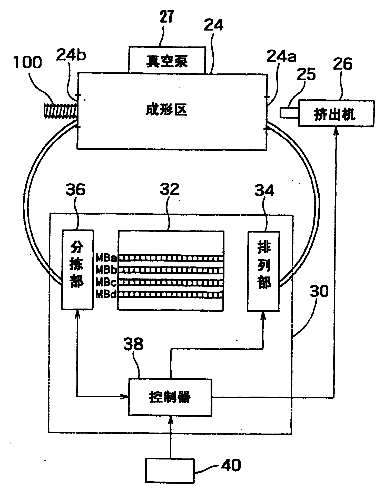
图1是本发明一实施形式所提供的波纹管制造装置的构成说明图。Fig. 1 is an explanatory view showing the structure of a bellows manufacturing device according to an embodiment of the present invention.
图2是该实施形式所提供的波纹管制造装置的编组部的构成框图。Fig. 2 is a block diagram of the formation part of the bellows manufacturing device provided by this embodiment.
图3是对模块列的编组样式的例子进行说明的说明图。FIG. 3 is an explanatory diagram illustrating an example of an arrangement pattern of a module column.
图4是波纹管的侧视图。Fig. 4 is a side view of the bellows.
图5是另一个实施形式所提供的波纹管制造装置的构成框图。Fig. 5 is a block diagram of a bellows manufacturing device provided by another embodiment.
图6是波纹管的形状要素图。Fig. 6 is a shape element diagram of a bellows.
图7是对现有技术所提供的波纹管制造装置的主要部分进行说明的说明图。Fig. 7 is an explanatory diagram for explaining main parts of a conventional corrugated tube manufacturing apparatus.
发明的最佳实施形式BEST MODE FOR CARRYING OUT THE INVENTION
下面,对本发明所提供的波纹管制造方法以及装置的一个实施形式,结合附图进行说明。Next, an implementation form of the bellows manufacturing method and device provided by the present invention will be described with reference to the accompanying drawings.
图1是对本实施形式所提供的波纹管制造装置的成形部进行展示的示意图。该图1中,参考编号20是整个第1模块列,参考编号22是整个第2模块列。Fig. 1 is a schematic diagram showing a forming section of a bellows manufacturing apparatus provided in this embodiment. In this FIG. 1 , reference numeral 20 is the entire first module column, and reference numeral 22 is the entire second module column.
图2是对进行第1模块列20的编组的编组部30的构成加以展示的构成框图。对第2模块列22进行编组的编组部的构成也与此相同,在图2中予以省略。FIG. 2 is a configuration block diagram showing the configuration of the organizing
第1模块列20与第2模块列22,是分别将与图6所示波纹管的波纹形状要素相对应的、分成两半的单位模块MB排列成一串而成。在这种场合,当单位模块MB需要与图6的波纹形状要素相对应时,对于与图6(a)的波纹形状要素A相对应的模块,在参考编号中添加a而用MBa表示之,同样地,对于与下面的形状要素B、C、D相对应的单位模块,在参考编号中添加b、c、d而加以区别。The first module row 20 and the second module row 22 are each formed by arranging unit modules MB divided into two halves corresponding to the corrugated shape elements of the corrugated tube shown in FIG. 6 in a row. In this case, when the unit module MB needs to correspond to the corrugated shape element of FIG. 6, for the module corresponding to the corrugated shape element A of FIG. Similarly, unit modules corresponding to the following shape elements B, C, and D are distinguished by adding b, c, and d to the reference numbers.
而且,第1模块列20的单位模块MBa与第2模块列22的单位模块MBa组合而构成旨在成形一个波纹形状要素A的模具。同样地,由第1模块列20的单位模块MBb与第2模块列22的单位模块MBb构成用来形成直管形状要素B的模具。在第1模块列20与第2模块列22中,单位模块MB的排列顺序是相同的。Then, the unit module MBa of the first module row 20 is combined with the unit module MBa of the second module row 22 to form a die for molding one corrugated shape element A. Similarly, the unit block MBb of the first block row 20 and the unit block MBb of the second block row 22 constitute a mold for forming the straight pipe shape element B. In the first module row 20 and the second module row 22 , the arrangement order of the unit modules MB is the same.
将这些第1模块列20和第2模块列22安装在未图示的皮带或链条上,向箭头所示的同方向以相同的速度移送。并且,成对的单位模块MB边逐渐合模边导入成形区24的入口部24a,在成形区24内重合而形成连续的模具。为了在成形区24的出口部24b使已成形的波纹管100脱模,单位模块MB边分模边被导离成形区。The first module row 20 and the second module row 22 are attached to a belt or a chain not shown, and are moved in the same direction indicated by the arrow at the same speed. Then, the paired unit modules MB are introduced into the
在成形区24的入口部24a附近,配置有挤出模25。挤出机26与该挤出模25相连接,从挤出机26通过加压送出来的熔融树脂,从挤出模25呈管状挤出到第1模块列20和第2模块列22之间。处于合模状态的单位模块MB、MB的内部,被真空泵27抽成真空,使得熔融树脂能够紧密贴合在闭合的单位模块MB、MB的内周面上。Near the
图1中,参考编号30是根据所要制造的波纹管的规格排列模块、进行第1模块列20、第2模块列22的编组的编组部。In FIG. 1 ,
图2中,编组部30具有:将单位模块MB以按类别排列好的状态暂时存放的模块存放部32;从模块存放部32中选择所需要的单位模块MB,使单位模块MB按照所指定的编组样式排列的排列部34;从自成形区24返回的第1模块列20中将各单位模块MB按类别进行分拣并送回模块存放部32中去的分拣部36;以及控制器38。In Fig. 2, the
下面,结合编组部30的各部的功能,对波纹管的制造工序进行说明。Next, the manufacturing process of the corrugated tube will be described in conjunction with the functions of each part of the forming
在本实施形式中,模块存放部32中存放的是,用来构成第1模块列20的4种单位模块MBa、MBb、MBc、MBd(它们分别对应于图6的形状要素A~D)。将这些单位模块MBa、MBb、MBc、MBd分别按类别排列成一排进行存放。In the present embodiment, four types of unit modules MBa, MBb, MBc, and MBd (corresponding to shape elements A to D in FIG. 6 , respectively) for constituting the first module array 20 are stored in the
排列部34,具有与控制器38相连接的排列装置,由控制器38向排列部34发出,针对构成第1模块列20的每一种单位模块MB的数量和顺序指定相关编组样式的编组指令。The
该编组样式的具体的例子示于图3。A specific example of this grouping pattern is shown in FIG. 3 .
样式1,是除了管子的两个端部为直管之外全部为波纹状这样一种管子的样式。对于该样式1,将端头指定为单位模块MBc,在其后续接与波纹部分的长度相应的既定数量的单位模块MBa,将串的最后指定为单位模块MBc。Pattern 1 is a pattern in which all pipes are corrugated except that both ends of the pipe are straight pipes. In this pattern 1, the terminal is designated as a unit module MBc, followed by a predetermined number of unit modules MBa corresponding to the length of the corrugated portion, and the end of the string is designated as a unit module MBc.
样式2,是管子的一端延续既定长度的直管部分后变成波纹状、另一个端部为直管这样一种管子的样式。对于该样式2,使与端头直管部分的长度相应的数量的单位模块MBb相连接,其后续接与波纹部分的长度相应的数量的单位模块MBa,将末端指定为单位模块MBc。
样式3,是与样式1相近的类型之中、在波纹部的中间具有直管部分这样一种管子的样式。对于该样式3,将端头指定为单位模块MBc,其后续接与直到位于中间的直管部分为止的波纹部分的长度相应的既定数量的单位模块MBa,接下来续接直管部分的单位模块MBd、以及、之后的波纹部分的单位模块MBa,将串的末尾指定为单位模块MBc。Pattern 3 is a pipe pattern that has a straight pipe part in the middle of the corrugated part among the types similar to pattern 1. For this style 3, the terminations are designated as unit modules MBc, followed by a predetermined number of unit modules MBa corresponding to the length of the corrugated section up to the straight section located in the middle, followed by unit modules of the straight section MBd and the subsequent unit block MBa of the wave portion designate the end of the string as the unit block MBc.
通过如上所述指定各种单位模块MBa、MBb、MBc、MBd的种类、数量进行排列,便可编组出与任意样式的波纹管相对应的模块列。By specifying the types and numbers of the various unit modules MBa, MBb, MBc, and MBd and arranging them as described above, it is possible to assemble a module row corresponding to any style of bellows.
其次,在如上进行编组而成的模块列在成形品脱模后从成形区24返回时,分拣部36对各单位模块MBa、MBb、MBc、MBd的种类进行识别,按其类别分拣并送回模块存放部32中。例如,在单位模块MBa、MBb、MBc、MBd上粘贴有能够以光学或磁学方法对其种类进行识别的识别标识,以检测传感器对该识别标识进行识别,分拣部36按类别进行分拣并送回模块存放部32中的按类别的排列中。Next, when the modules grouped as above are returned from the forming
另外,作为分拣部36,可以采用,具有通过检测传感器识别单位模块MBa、MBb、MBc、MBd、夹持单位模块MBa、MBb、MBc、MBd按其类别送回模块存放部32的队列中的功能的工业用机器人。此外,也可以设计成,按照单位模块MBa、MBb、MBc、MBd的类别,设置从分拣部36向模块存放部32延伸的导轨和道岔的切换机构,沿该导轨移送单位模块,并根据检测传感器的识别结果使切换机构动作,从而对单位模块MBa、MBb、MBc、MBd进行分拣。In addition, as the sorting
下面,结合图1、图2对制造工序进行说明。Next, the manufacturing process will be described with reference to FIGS. 1 and 2 .
控制器38中已输入了与所要制造的波纹管的规格相对应的单位模块编组样式数据40。作为该编组样式数据40,也可以预先存储数种编组样式,由控制器38来指定任意一种编组样式。Unit module
当控制器38向排列部34发出编组样式指令时,该排列部34,从在模块存放部32中排列好的相应类别的单位模块MBa、MBb、MBc、MBd的端头一个一个地依次取出所需要的单位模块,编组成符合指令所指定的样式的第1模块列20、第2模块列22。当编组而成的第1模块列20、第2模块列22移动到移送装置上时,控制器38驱动移送装置将第1模块列20和第2模块列22以相同的速度向成形区24移送。When the
在成形区24的入口部24a处,从挤出机26的挤出模25向第1模块列20和第2模块列22之间挤出熔融树脂,继而,在第1模块列20和第2模块列22在向同方向移动的同时合模后,真空泵27进行抽吸使模具内部产生负压,熔融树脂将紧密贴合在第1模块列20、第2模块列22的内周面上而成形为波纹管100,。在成形区24的出口部24b处,第1模块列20和第2模块列22分模,成形后的波纹管100边脱模边原样直线前进。At the
另一方面,第1模块列20和第2模块列22分别返回分拣部36。在该分拣部36中,将第1模块列20、第2模块列22,分别按单位模块MBa、MBb、MBc、MBd的类别进行分拣,送回模块存放部32中的不同类别的队列中。On the other hand, the first module row 20 and the second module row 22 are each returned to the
这样,一个成形循环便结束。若继续成形相同规格的波纹管,只要依照相同的模块列编组样式重复上述成形循环即可。In this way, a forming cycle is ended. To continue to form bellows of the same specification, just repeat the above forming cycle according to the same module column grouping pattern.
而若要成形不同规格的波纹管,只要由控制器38重新向排列部34发出相应编组样式的指令即可。于是,排列部34将按照指令要求,改变第1模块列20、第2模块列22的编组,之后将它们送往成形区24。And if it is desired to form corrugated tubes of different specifications, the
按照以上方法,改变模块列的编组样式时,不需要将设备停下来进行改装工作,并能够按照任意的编组样式连续地成形波纹管,因此,不再产生空置时间,可大幅度提高生产率。According to the above method, when changing the grouping pattern of the module row, it is not necessary to stop the equipment for refitting work, and the bellows can be continuously formed according to an arbitrary grouping pattern, so there is no idle time, and the productivity can be greatly improved.
此外,由于不需要进行改装工作并能够按照任意编组样式连续进行成形,因而树脂不会滞留在挤出机等设备中,因此,可避免树脂材料的浪费和老化,提高生产率。In addition, since there is no need for modification work and continuous molding can be performed in any group pattern, resin does not remain in equipment such as extruders, so waste and deterioration of resin materials can be avoided, and productivity can be improved.
在这里,图4示出本发明的另一个实施形式。与图2的实施形式的不同之处在于,由从挤出模25挤出出来的树脂的内部施加内压,以替代对成形区24内部进行抽真空的做法。为此,在成形区24的入口处设置了内压加压部28,可使树脂紧密贴合在边合模边在成形区24内移动的模块列的内周面上而成形为波纹管。FIG. 4 here shows another embodiment of the invention. The difference from the embodiment shown in FIG. 2 is that the internal pressure is applied from the inside of the resin extruded from the extrusion die 25 instead of evacuating the inside of the
由以上说明可知,根据本发明,能够不进行改装工作而改变随着波纹管规格的改变而改变的模块的排列样式,能够在机械设备不停止工作的情况下,自由改变模块的排列样式而连续地制造波纹管。As can be seen from the above description, according to the present invention, the arrangement pattern of the modules that changes with the change of the bellows specifications can be changed without refitting, and the arrangement pattern of the modules can be freely changed without stopping the operation of the mechanical equipment to continuously to manufacture bellows.
Claims (8)
Applications Claiming Priority (2)
| Application Number | Priority Date | Filing Date | Title |
|---|---|---|---|
| JP378306/2001 | 2001-12-12 | ||
| JP2001378306A JP3883859B2 (en) | 2001-12-12 | 2001-12-12 | Bellows tube manufacturing method and apparatus |
Publications (2)
| Publication Number | Publication Date |
|---|---|
| CN1604838A CN1604838A (en) | 2005-04-06 |
| CN100354103C true CN100354103C (en) | 2007-12-12 |
Family
ID=19186066
Family Applications (1)
| Application Number | Title | Priority Date | Filing Date |
|---|---|---|---|
| CNB028250281A Expired - Fee Related CN100354103C (en) | 2001-12-12 | 2002-12-09 | Bellows manufacturing method and device |
Country Status (7)
| Country | Link |
|---|---|
| US (1) | US20050012249A1 (en) |
| EP (1) | EP1473136A4 (en) |
| JP (1) | JP3883859B2 (en) |
| CN (1) | CN100354103C (en) |
| CA (1) | CA2469694A1 (en) |
| MX (1) | MXPA04005052A (en) |
| WO (1) | WO2003049919A1 (en) |
Families Citing this family (9)
| Publication number | Priority date | Publication date | Assignee | Title |
|---|---|---|---|---|
| DE102006048512B4 (en) * | 2006-10-13 | 2014-03-06 | Ralph Peter Hegler | Apparatus for producing composite pipes |
| JP6131094B2 (en) * | 2013-05-09 | 2017-05-17 | 矢崎総業株式会社 | Corrugated tube manufacturing apparatus and corrugated tube manufacturing method |
| JP6211386B2 (en) * | 2013-10-23 | 2017-10-11 | 矢崎総業株式会社 | Manufacturing method of harness exterior protective material |
| EP3110619B1 (en) * | 2014-02-25 | 2019-04-10 | Sns Unicorp Pty. Ltd. | Method and apparatus for forming profiled articles |
| CN105690717B (en) * | 2016-01-29 | 2018-02-06 | 姜维雁 | Manufacturing system and manufacturing method of sealed heat preservation pipe |
| DE102016112421B4 (en) * | 2016-07-06 | 2021-10-21 | Schlemmer Gmbh | Corrugator, extrusion system and process |
| CN108859054B (en) * | 2018-08-07 | 2023-12-05 | 江苏烨欣塑业有限公司 | HDPE farmland irrigation pipe preparation method, HDPE farmland irrigation pipe and manufacturing device |
| DE102019212130A1 (en) * | 2019-08-13 | 2021-02-18 | Fränkische Industrial Pipes GmbH & Co. KG | CHANGING CORRUGATOR |
| JP2025117253A (en) * | 2024-01-30 | 2025-08-12 | 三桜工業株式会社 | Joint pipe and manufacturing method of joint pipe |
Citations (5)
| Publication number | Priority date | Publication date | Assignee | Title |
|---|---|---|---|---|
| JPS61148036A (en) * | 1984-12-21 | 1986-07-05 | Takiron Co Ltd | Manufacture of double wall pipe |
| WO1995001251A1 (en) * | 1993-06-30 | 1995-01-12 | Lupke Manfred Arno Alfred | Method and apparatus for forming a double walled thermoplastic tube with integral bells |
| JPH07171882A (en) * | 1993-10-28 | 1995-07-11 | Tigers Polymer Corp | Method of manufacturing flexible hose and flexible hose |
| EP1044775A2 (en) * | 1999-04-01 | 2000-10-18 | FRÄNKISCHE ROHRWERKE, GEBR. KIRCHNER GmbH & Co. | Corrugator with means to exchange moulding elements |
| CN1068827C (en) * | 1995-09-22 | 2001-07-25 | 拉尔夫·P·赫格勒 | Apparatus for making thermoplastic tubes characterized by transverse shapes |
Family Cites Families (7)
| Publication number | Priority date | Publication date | Assignee | Title |
|---|---|---|---|---|
| US3286305A (en) * | 1964-09-03 | 1966-11-22 | Rexall Drug Chemical | Apparatus for continuous manufacture of hollow articles |
| US3430292A (en) * | 1967-04-28 | 1969-03-04 | Acme Hamilton Mfg Corp | Apparatus for the continuous formation of tubular articles |
| US4325685A (en) * | 1980-09-12 | 1982-04-20 | Lupke Manfred Arno Alfred | Apparatus for producing thermoplastic tubing having interchangeable mold blocks |
| DE69121410T2 (en) * | 1991-06-14 | 1997-02-20 | Manfred Arno Alfred Lupke | MACHINE WITH MIGRATING SHAPED TUNNEL FOR THE PRODUCTION OF SMALL-WALLED TUBES |
| US5460771A (en) * | 1992-10-16 | 1995-10-24 | Itt Corporation | Process for producing corrugated multi-layer tubing having layers of differing plastic characteristics |
| CA2271395C (en) * | 1999-05-07 | 2006-07-11 | Manfred A. A. Lupke | Molding apparatus with mold block replacement system |
| DE10110775B4 (en) * | 2001-03-07 | 2013-03-14 | Ralph-Peter Hegler | Method and device for producing thermoplastic pipes with transverse profiling |
-
2001
- 2001-12-12 JP JP2001378306A patent/JP3883859B2/en not_active Expired - Fee Related
-
2002
- 2002-12-09 CA CA002469694A patent/CA2469694A1/en not_active Abandoned
- 2002-12-09 EP EP02786062A patent/EP1473136A4/en not_active Withdrawn
- 2002-12-09 US US10/496,220 patent/US20050012249A1/en not_active Abandoned
- 2002-12-09 CN CNB028250281A patent/CN100354103C/en not_active Expired - Fee Related
- 2002-12-09 WO PCT/JP2002/012865 patent/WO2003049919A1/en not_active Ceased
- 2002-12-09 MX MXPA04005052A patent/MXPA04005052A/en active IP Right Grant
Patent Citations (5)
| Publication number | Priority date | Publication date | Assignee | Title |
|---|---|---|---|---|
| JPS61148036A (en) * | 1984-12-21 | 1986-07-05 | Takiron Co Ltd | Manufacture of double wall pipe |
| WO1995001251A1 (en) * | 1993-06-30 | 1995-01-12 | Lupke Manfred Arno Alfred | Method and apparatus for forming a double walled thermoplastic tube with integral bells |
| JPH07171882A (en) * | 1993-10-28 | 1995-07-11 | Tigers Polymer Corp | Method of manufacturing flexible hose and flexible hose |
| CN1068827C (en) * | 1995-09-22 | 2001-07-25 | 拉尔夫·P·赫格勒 | Apparatus for making thermoplastic tubes characterized by transverse shapes |
| EP1044775A2 (en) * | 1999-04-01 | 2000-10-18 | FRÄNKISCHE ROHRWERKE, GEBR. KIRCHNER GmbH & Co. | Corrugator with means to exchange moulding elements |
Also Published As
| Publication number | Publication date |
|---|---|
| MXPA04005052A (en) | 2004-08-19 |
| EP1473136A1 (en) | 2004-11-03 |
| WO2003049919A1 (en) | 2003-06-19 |
| CA2469694A1 (en) | 2003-06-19 |
| JP2003175539A (en) | 2003-06-24 |
| EP1473136A4 (en) | 2006-03-29 |
| US20050012249A1 (en) | 2005-01-20 |
| CN1604838A (en) | 2005-04-06 |
| JP3883859B2 (en) | 2007-02-21 |
Similar Documents
| Publication | Publication Date | Title |
|---|---|---|
| CN100354103C (en) | Bellows manufacturing method and device | |
| US12508763B2 (en) | Device and method for manufacturing plastic containers | |
| CN100384613C (en) | Hollow product made of thermoplastic resin, its manufacturing method and manufacturing equipment | |
| CN1112050A (en) | Compact core and ejector assembly | |
| CN87100836A (en) | The device that is used for molding thermoplastic pipes | |
| CN101784377B (en) | Method of moulding object of indefinite length using an injection mould apparatus | |
| CN117818085B (en) | Multilayer continuous molding process for plastic bottle | |
| JP2019524488A (en) | Corrugator, extrusion system and method | |
| US5762970A (en) | Parison forming apparatus including core insert and parison transfer devices for forming a composite parison | |
| US6471907B1 (en) | Shuttle-type blow molding method and apparatus | |
| CN111246986B (en) | Method for producing components from preforms designed as hollow bodies | |
| JP2024545306A (en) | Apparatus for the continuous cycle production of containers from plastic materials | |
| CN111251574B (en) | Mold for cross-specification production of high-density large-caliber polyethylene pipe | |
| CN101878103B (en) | Method and device for producing double-walled thermoplastic corrugated pipe having a connecting sleeve | |
| US6168750B1 (en) | System and method for preforming an extruded parison | |
| CN104260310B (en) | Device for manufacturing fiber materials and product by laminating method | |
| CN1960849A (en) | Method and device for extrusion/molding of thermoplastic hollow bodies | |
| KR101173460B1 (en) | Mult-pipe for communication cable and apparatus for making the same | |
| CN115702074B (en) | Method for forming a container with a suspension device | |
| CN220464613U (en) | Shaping equipment for automobile nonmetallic accessories | |
| CN216708300U (en) | Vortex double-layer extrusion molding machine head for solving problem of double-layer pipe extrusion layering | |
| CN223173455U (en) | Multimode PET bottle embryo mould | |
| CN219505413U (en) | Single-station injection stretch blow dust cover die | |
| JPH05154896A (en) | Manufacturing method of tubular body | |
| CN119682137A (en) | A bottle embryo production device |
Legal Events
| Date | Code | Title | Description |
|---|---|---|---|
| C06 | Publication | ||
| PB01 | Publication | ||
| C10 | Entry into substantive examination | ||
| SE01 | Entry into force of request for substantive examination | ||
| C14 | Grant of patent or utility model | ||
| GR01 | Patent grant | ||
| CF01 | Termination of patent right due to non-payment of annual fee |
Granted publication date: 20071212 Termination date: 20151209 |
|
| EXPY | Termination of patent right or utility model |