CN100366875C - compressor wheel assembly - Google Patents
compressor wheel assembly Download PDFInfo
- Publication number
- CN100366875C CN100366875C CNB200310119812XA CN200310119812A CN100366875C CN 100366875 C CN100366875 C CN 100366875C CN B200310119812X A CNB200310119812X A CN B200310119812XA CN 200310119812 A CN200310119812 A CN 200310119812A CN 100366875 C CN100366875 C CN 100366875C
- Authority
- CN
- China
- Prior art keywords
- shaft
- compressor wheel
- wheel
- turbocharger
- compressor
- Prior art date
- Legal status (The legal status is an assumption and is not a legal conclusion. Google has not performed a legal analysis and makes no representation as to the accuracy of the status listed.)
- Expired - Fee Related
Links
Images

Classifications
-
- B—PERFORMING OPERATIONS; TRANSPORTING
- B21—MECHANICAL METAL-WORKING WITHOUT ESSENTIALLY REMOVING MATERIAL; PUNCHING METAL
- B21H—MAKING PARTICULAR METAL OBJECTS BY ROLLING, e.g. SCREWS, WHEELS, RINGS, BARRELS, BALLS
- B21H7/00—Making articles not provided for in the preceding groups, e.g. agricultural tools, dinner forks, knives, spoons
- B21H7/16—Making articles not provided for in the preceding groups, e.g. agricultural tools, dinner forks, knives, spoons turbine blades; compressor blades; propeller blades
-
- F—MECHANICAL ENGINEERING; LIGHTING; HEATING; WEAPONS; BLASTING
- F04—POSITIVE - DISPLACEMENT MACHINES FOR LIQUIDS; PUMPS FOR LIQUIDS OR ELASTIC FLUIDS
- F04D—NON-POSITIVE-DISPLACEMENT PUMPS
- F04D29/00—Details, component parts, or accessories
- F04D29/26—Rotors specially for elastic fluids
- F04D29/266—Rotors specially for elastic fluids mounting compressor rotors on shafts
Landscapes
- Engineering & Computer Science (AREA)
- Mechanical Engineering (AREA)
- General Engineering & Computer Science (AREA)
- Life Sciences & Earth Sciences (AREA)
- Agronomy & Crop Science (AREA)
- Structures Of Non-Positive Displacement Pumps (AREA)
- Supercharger (AREA)
- ing And Chemical Polishing (AREA)
Abstract
一种涡轮增压器包括安装在涡轮增压器轴(8)的一端处的压缩机转轮(7)。通过将一螺母(17)拧到轴(8)的一端将转轮(7)夹紧到轴上从而防止转轮(7)沿轴(8)发生轴向移动和旋转滑动。通过对联接部分的接触表面进行处理来增大它们的摩擦系数从而增大压缩机转轮(7)和螺母(17)之间的联接承载扭矩的能力。
A turbocharger includes a compressor wheel (7) mounted at one end of a turbocharger shaft (8). Axial movement and rotational slippage of the runner (7) along the shaft (8) is prevented by clamping the runner (7) to the shaft by screwing a nut (17) onto one end of the shaft (8). The torque carrying capacity of the coupling between the compressor wheel (7) and the nut (17) is increased by treating the contact surfaces of the coupling parts to increase their coefficient of friction.
Description
技术领域 technical field
本发明涉及装配在转轴上的压缩机转轮组件。本发明尤其涉及一涡轮增压器的压缩机转轮组件。The present invention relates to compressor wheel assemblies mounted on shafts. More particularly, the present invention relates to a turbocharger compressor wheel assembly.
背景技术 Background technique
众所周知的是涡轮增压器是在一高于大气压的压力下(升压)将空气输入到内燃机入口处的装置。传统的涡轮增压器主要包括一安装在涡轮机壳体内的转轴上由排放气体驱动的涡轮机转轮。涡轮机转轮的旋转带动安装在压缩机壳体内的转轴的另一端上的压缩机转轮进行旋转。压缩机转轮将压缩空气输送到发动机的进气歧管中,由此增加发动机的动力。该轴由连接于涡轮机和压缩机转轮室之间的中心轴承室内的径向推力轴承支承。It is well known that a turbocharger is a device for feeding air at a pressure above atmospheric pressure (boost) to the intake of an internal combustion engine. A conventional turbocharger basically consists of a turbine wheel driven by exhaust gases on a shaft mounted in a turbine housing. The rotation of the turbine wheel rotates the compressor wheel mounted on the other end of the shaft in the compressor housing. The compressor wheel delivers compressed air into the engine's intake manifold, thereby increasing the engine's power. The shaft is supported by radial thrust bearings connected in a central bearing chamber between the turbine and compressor wheel chambers.
传统的压缩机转轮包括一组从中心轮毂上延伸的叶片,其中该中心轮毂上有用于安装涡轮增压器轴的一端的孔。通过把一螺母拧到所述轴的一端上将压缩机转轮固定在轴上,在此处该螺母延伸穿过转轮孔,并且压紧在转轮的前端,从而将该转轮夹紧在一轴肩处(或者其它的和所述轴一起旋转的径向延伸的支座)。重要的是要使夹紧力足够大以防止转轮在轴上发生滑动,而这种滑动会使转轮失去平衡。失去平衡的转轮至少会使其振动增加,这种振动会缩短转轮的寿命,并且在最坏的情况下这种振动会带来致命的损坏。A conventional compressor wheel includes a set of blades extending from a central hub with a bore for receiving one end of a turbocharger shaft. The compressor wheel is secured to the shaft by screwing a nut onto one end of the shaft where the nut extends through the hole in the wheel and compresses against the front end of the wheel, thereby clamping the wheel At a shaft shoulder (or other radially extending seat that rotates with the shaft). It is important to have enough clamping force to prevent the runner from slipping on the shaft, which would throw the runner out of balance. An out-of-balance rotor will at least increase its vibration, which will shorten the life of the rotor and, at worst, cause fatal damage.
现在对涡轮增压器性能的需求要求增大来自一给定尺寸的涡轮增压器的空气流,从而提高转速,例如超过100,000rpm。为了达到这种高转速,必须使涡轮增压器的轴承和由此带来的涡轮增压器轴的直径达到最小。然而,使用直径相对小的轴会给传统的压缩机转轮的装配组件带来问题,原因是,必须使轴能承受为防止转轮滑动所需要的高夹紧力。因此,轴的强度,即,它能承受的夹紧力负荷可能会限制安装在轴上的压缩机转轮的质量。Today's demands on turbocharger performance require increased air flow from a turbocharger of a given size, thereby increasing the rotational speed, eg, over 100,000 rpm. In order to achieve such high rotational speeds, the diameter of the turbocharger bearings and thus the turbocharger shaft must be minimized. However, the use of relatively small diameter shafts presents problems in conventional compressor wheel assembly assemblies because the shaft must be made to withstand the high clamping forces required to prevent the wheel from slipping. Therefore, the strength of the shaft, ie the clamping force load it can withstand may limit the mass of the compressor wheel mounted on the shaft.
由于涡轮增压器的持续发展要求使用性能较高的材料,如具有比通常使用的铝合金密度更大的钛,这样上述问题被恶化了。这种材料增加的惯量增加了压缩机转轮滑动的可能性,特别是当在瞬时运行条件下涡轮机转轮快速加速时。这种来自传统的压缩机转轮的装配组件所要求的夹紧力可能会极大地超出轴能承受的夹紧力。This problem is exacerbated by the continued development of turbochargers requiring the use of higher performance materials such as titanium having a higher density than the aluminum alloys commonly used. The increased inertia of this material increases the likelihood of compressor wheel slippage, especially when the turbine wheel accelerates rapidly under transient operating conditions. The clamping force required for such an assembly assembly from a conventional compressor wheel can greatly exceed the clamping force that the shaft can withstand.
为避免上述问题可能采用的一个方法是使用一个例如美国专利第4,705,463号中披露的所谓的“无孔”压缩机转轮。采用这种压缩机转轮的组件,其压缩机转轮上仅仅只有一个相对较短的螺纹孔,缩短的涡轮增压器轴的螺纹端装配在其内。然而,由于压缩机转轮和轴之间的螺纹连接和在这种连接中所固有的间隙可能会造成很难保持所需要的同心度的问题,因此这种组件也会产生平衡的问题。One possible approach to avoid the above-mentioned problems is to use a so-called "holeless" compressor wheel such as that disclosed in US Patent No. 4,705,463. With this compressor wheel assembly, there is only a relatively short threaded hole in the compressor wheel into which the threaded end of the shortened turbocharger shaft fits. However, such assemblies also create balancing problems because the threaded connection between the compressor wheel and shaft and the clearances inherent in such a connection can make it difficult to maintain the desired concentricity.
发明内容 Contents of the invention
本发明的一个目的是为了消除或者减轻上述问题。It is an object of the present invention to eliminate or alleviate the above-mentioned problems.
根据本发明的第一方面,提供一种涡轮增压器,它包括安装在涡轮机壳体内的转轴的第一端上的涡轮机转轮,和安装在压缩机壳体内的转轴的第二端上的压缩机转轮,该压缩机转轮具有一延伸在转轮的第一端和转轮的第二端之间的轴向通孔,所述第二端远离所述涡轮机,其中轴的第二端延伸穿过该孔,并且在压缩机转轮的第二端之外伸出一短的长度,将一螺母拧到轴的所述第二端上,从而直接地将夹紧力施加到压缩机转轮上,或通过一设置在与压缩机转轮第二端相邻的所述轴的周围的中间夹紧部件间接地将夹紧力施加到压缩机转轮上,这样压缩机转轮的第二端具有一与螺母或中间夹紧部件的径向表面相接触的径向表面,并且对所述径向表面其中的至少一个面进行处理用以提高它相对于另一表面的摩擦系数。According to a first aspect of the present invention there is provided a turbocharger comprising a turbine wheel mounted on a first end of a shaft in a turbine housing, and a second end of the shaft mounted in a compressor housing A compressor wheel having an axial through hole extending between a first end of the wheel and a second end of the wheel, said second end being remote from said turbine, wherein the first end of the shaft Two ends extend through this hole, and protrude a short length beyond the second end of compressor wheel, and a nut is screwed on the said second end of axle, thereby directly clamping force is applied to on the compressor wheel, or indirectly through an intermediate clamping member disposed around said shaft adjacent to the second end of the compressor wheel, to apply a clamping force to the compressor wheel so that the compressor wheel The second end of the wheel has a radial surface in contact with the radial surface of the nut or the intermediate clamping member, and at least one of said radial surfaces is treated to increase its friction against the other surface coefficient.
因此,本发明不需对压缩机转轮组件进行大的改进便提高了夹紧联接部分承载扭矩的能力。该表面处理可以是例如简单地提高相关表面的粗糙度,例如通过激光在表面上蚀刻一适合的图案。Thus, the present invention increases the torque carrying capacity of the clamp coupling without requiring major modifications to the compressor wheel assembly. The surface treatment may for example simply increase the roughness of the relevant surface, eg by etching a suitable pattern on the surface with a laser.
本发明也提供了一种在制造上述涡轮增压器中用于提高压缩机转轮的轴向夹紧组件承载扭矩的能力的方法,所述方法包括对所述径向表面的至少一个面进行处理以增大它相对于另一表面的摩擦系数。The present invention also provides a method for improving the torque-carrying capacity of an axial clamping assembly of a compressor wheel in the manufacture of the above-mentioned turbocharger, said method comprising subjecting at least one of said radial surfaces to Treated to increase its coefficient of friction against another surface.
附图说明 Description of drawings
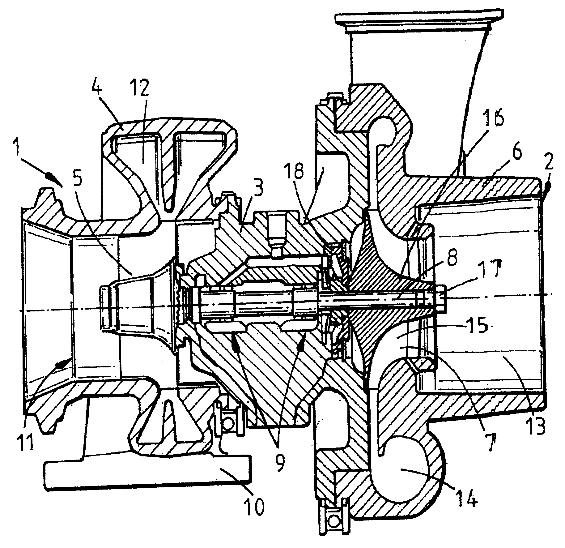
现在仅仅通过举例并结合附图的方式对本发明的具体实施例进行描述,其中附图示出一传统的涡轮增压器的轴剖面图,用以说明传统的涡轮增压器和传统的压缩机转轮组件的主要部件。Embodiments of the present invention will now be described, by way of example only, with reference to the accompanying drawing, which shows a conventional turbocharger in axial section to illustrate a conventional turbocharger and a conventional compressor Main component of the runner assembly.
具体实施方式 Detailed ways
图示的涡轮增压器包括经一中央轴承室3连接到压缩机2上的涡轮机1。该涡轮机1包括一容纳涡轮机转轮5的涡轮机壳体4。类似地,压缩机2包括容纳压缩机转轮7的压缩机壳体6。涡轮机转轮5和压缩机转轮7安装在一共用轴8的相对端上,该轴8由位于轴承室3内的轴承组件9支承。The illustrated turbocharger comprises a turbine 1 connected to a compressor 2 via a central bearing chamber 3 . The turbine 1 comprises a
涡轮机壳体4设有一排放气体进口10和一排放气体出口11。进口10将引入的排放气体导入到涡轮机转轮5周围的环形进气腔12内。排放气体流经涡轮机并且经一与涡轮机转轮5同轴的圆形排气开口流入到排气出口11。涡轮机转轮5旋转带动压缩机转轮7旋转,该压缩机转轮通过轴向进口13将空气吸入并且经环形的出气涡腔14将压缩空气输送到发动机进口处。The
现在对压缩机转轮组件进行更详细的描述,该压缩机转轮包括若干从中心轮毂16上延伸的叶片15,该中心轮毂16具有一用于安装轴8的一端的通孔。该轴8从压缩机转轮7的前端处延伸出一小部分,并且将一螺母17拧在轴8上,该螺母17压在压缩机转轮的前端从而将压缩机转轮7夹紧在推力轴承和油封组件18上。推力轴承/油封组件的细节可以改变并且对理解压缩机转轮安装结构并不重要。实质问题是,通过由螺母17施加的夹紧力防止压缩机转轮7在轴8上发生滑动。The compressor wheel assembly will now be described in more detail, the compressor wheel comprising a number of
在本说明书的介绍中将会讨论上述传统的压缩机转轮组件所带来的问题。The problems associated with the conventional compressor wheel assembly described above will be discussed in the introduction to this specification.
根据本发明,在不增加夹紧力或者不对夹紧部件进行显著的改进的情况下,可以加大传递给压缩机转轮的旋转驱动力。这是通过对部件的夹紧表面进行处理提高它们之间的摩擦系数来实现的。According to the present invention, it is possible to increase the rotational driving force transmitted to the compressor wheel without increasing the clamping force or making significant modifications to the clamping components. This is achieved by treating the clamping surfaces of the components to increase the coefficient of friction between them.
参照图1的传统的夹紧组件,可以对螺母17压紧的压缩机转轮7的前端部件的径向表面进行处理从而提高它相对于螺母的摩擦系数,例如通过增加它的表面粗糙度提高它相对于螺母的摩擦系数。例如,可以用激光在其表面上蚀刻出一适合的图案来增加其表面粗糙度。这样就可以在不牺牲部件形成公差的条件下使夹紧点可承载的扭矩增大。Referring to the conventional clamping assembly of FIG. 1, the radial surface of the front part of the
除了对压缩机转轮的表面进行处理,还可以或仅仅对螺母的接触表面进行类似的处理,从而又一次地增大接触表面之间的摩擦系数。In addition to the surface treatment of the compressor wheel, a similar treatment may also or only be performed on the contact surfaces of the nut, thereby again increasing the coefficient of friction between the contact surfaces.
在某些夹紧结构中,在压缩机转轮和螺母之间设置一垫圈或其它类似物,在这种情况下可对与压缩机转轮相接触的垫圈表面进行处理使其摩擦系数增大。In some clamping configurations, a washer or the like is placed between the compressor wheel and the nut, in which case the surface of the washer in contact with the compressor wheel can be treated to increase the coefficient of friction .
加大压缩机转轮的后表面和推力轴承组件之间的摩擦系数,或者加大其它的由螺母17施加的力将压缩机转轮夹紧在其上的径向表面之间的摩擦系数也是可取的。在上述所示实施例中,也应该包括对压缩机转轮的后表面或推力轴承组件的径向表面进行处理。在其它的实施例中,轴可以具有一环状的肩部,该肩部靠压在压缩机转轮的后表面上并且也可对其进行类似的处理。Increasing the coefficient of friction between the rear surface of the compressor wheel and the thrust bearing assembly, or other radial surfaces against which the force exerted by the
应该理解的是除了激光蚀刻之外还有其它的表面处理方法可以用来补充本发明,包括增加相应种材料的表面粗糙度所适合的机械的或者化学的处理方法。这些适合的表面处理方法对于本领域的技术人员来说都是显而易见的。It should be understood that other surface treatments besides laser etching may be used to complement the present invention, including mechanical or chemical treatments suitable for increasing the surface roughness of the respective material. Such suitable surface treatments will be apparent to those skilled in the art.
Claims (13)
Applications Claiming Priority (2)
| Application Number | Priority Date | Filing Date | Title |
|---|---|---|---|
| GB0224727.8 | 2002-10-24 | ||
| GBGB0224727.8A GB0224727D0 (en) | 2002-10-24 | 2002-10-24 | Compressor wheel assembly |
Publications (2)
| Publication Number | Publication Date |
|---|---|
| CN1523212A CN1523212A (en) | 2004-08-25 |
| CN100366875C true CN100366875C (en) | 2008-02-06 |
Family
ID=9946479
Family Applications (1)
| Application Number | Title | Priority Date | Filing Date |
|---|---|---|---|
| CNB200310119812XA Expired - Fee Related CN100366875C (en) | 2002-10-24 | 2003-10-24 | compressor wheel assembly |
Country Status (7)
| Country | Link |
|---|---|
| US (1) | US7010917B2 (en) |
| EP (1) | EP1413765B1 (en) |
| JP (1) | JP2004144097A (en) |
| KR (1) | KR20040036658A (en) |
| CN (1) | CN100366875C (en) |
| DE (1) | DE60304128T2 (en) |
| GB (1) | GB0224727D0 (en) |
Families Citing this family (19)
| Publication number | Priority date | Publication date | Assignee | Title |
|---|---|---|---|---|
| GB0224721D0 (en) * | 2002-10-24 | 2002-12-04 | Holset Engineering Co | Compressor wheel assembly |
| GB0224726D0 (en) * | 2002-10-24 | 2002-12-04 | Holset Engineering Co | Compressor wheel assembly |
| GB0224723D0 (en) * | 2002-10-24 | 2002-12-04 | Holset Engineering Co | Compressor wheel assembly |
| GB0425088D0 (en) | 2004-11-13 | 2004-12-15 | Holset Engineering Co | Compressor wheel |
| JP2008202544A (en) * | 2007-02-21 | 2008-09-04 | Mitsubishi Heavy Ind Ltd | Manufacturing method of rotor, and exhaust turbocharger having the rotor |
| FR2934340B1 (en) * | 2008-07-23 | 2010-09-10 | Snecma | METHOD FOR INCREASING THE COEFFICIENT OF ADHESION BETWEEN TWO SOLIDARITY PARTS IN ROTATION OF A ROTOR |
| DE102008053222A1 (en) | 2008-10-25 | 2010-04-29 | Bosch Mahle Turbo Systems Gmbh & Co. Kg | turbocharger |
| DE102008055706A1 (en) * | 2008-11-03 | 2010-05-06 | Volkswagen Ag | Device for fastening wheel on shaft, has shaft and wheel arranged at shaft, where wheel is provided between fastening element and counter bearing |
| DE112010001369T5 (en) | 2009-03-25 | 2012-05-16 | Borgwarner Inc. | REDUCING TURBOCHARGER NUCLEAR WITH CENTERING DEVICE |
| US8453448B2 (en) * | 2010-04-19 | 2013-06-04 | Honeywell International Inc. | Axial turbine |
| FR2965020B1 (en) * | 2010-09-17 | 2012-10-12 | Poclain Hydraulics Ind | HYDRAULIC DEVICE |
| DE102011004345A1 (en) | 2011-02-17 | 2012-08-23 | Bayerische Motoren Werke Aktiengesellschaft | Exhaust gas turbocharger for an internal combustion engine |
| WO2014025554A1 (en) * | 2012-08-07 | 2014-02-13 | Borgwarner Inc. | Compressor wheel with balance correction and positive piloting |
| DE102014213641A1 (en) * | 2014-01-17 | 2015-08-06 | Borgwarner Inc. | Method for connecting a compressor wheel with a shaft of a charging device |
| US9879536B2 (en) * | 2015-12-21 | 2018-01-30 | General Electric Company | Surface treatment of turbomachinery |
| DE102016103115B4 (en) * | 2016-02-23 | 2024-10-24 | Ihi Charging Systems International Gmbh | rotor for an exhaust turbocharger |
| JP6625959B2 (en) * | 2016-11-17 | 2019-12-25 | 株式会社名光精機 | Impeller and method of manufacturing the same |
| JP7187668B2 (en) * | 2019-03-14 | 2022-12-12 | 三菱重工エンジン&ターボチャージャ株式会社 | Compressor wheel device and turbocharger |
| US10746099B1 (en) * | 2019-04-03 | 2020-08-18 | GM Global Technology Operations LLC | Multi-step bore turbocharger |
Citations (2)
| Publication number | Priority date | Publication date | Assignee | Title |
|---|---|---|---|---|
| US4519747A (en) * | 1982-01-20 | 1985-05-28 | Toyota Jidosha Kogyo Kabushiki Kaisha | Method for assembling an impeller onto a turboshaft |
| US6449950B1 (en) * | 2000-09-12 | 2002-09-17 | Honeywell International Inc. | Rotor and bearing system for electrically assisted turbocharger |
Family Cites Families (15)
| Publication number | Priority date | Publication date | Assignee | Title |
|---|---|---|---|---|
| US2799445A (en) * | 1955-12-12 | 1957-07-16 | Gen Electric | High speed rotor |
| SU531930A1 (en) | 1974-04-05 | 1976-10-15 | Коломенский Тепловозостроительный Завод Им. В.В.Куйбышева | Rotor of a centrifugal compressor |
| JPS5823587A (en) | 1981-08-06 | 1983-02-12 | Tomoegumi Giken:Kk | Method and device for treatment of frictional fayed face |
| DE3268013D1 (en) * | 1981-08-18 | 1986-01-30 | Bbc Brown Boveri & Cie | Exhaust-gas turbocharger with bearings between turbine and compressor |
| US4705463A (en) * | 1983-04-21 | 1987-11-10 | The Garrett Corporation | Compressor wheel assembly for turbochargers |
| US4722630A (en) * | 1985-09-20 | 1988-02-02 | The Garrett Corporation | Ceramic-metal braze joint |
| DE4445296C1 (en) * | 1994-12-19 | 1996-08-22 | Man B & W Diesel Ag | Radial compressor wheel impeller having low noise level |
| US5690632A (en) | 1995-11-30 | 1997-11-25 | Schwartz; Paul Steven | Osteosynthesis screw fastener having angularly adjustable threads and methods of use therefor |
| JP3443124B2 (en) * | 1997-03-29 | 2003-09-02 | ドイッチェ テレコム アーゲー | Fiber integrated photonic crystal and its system |
| JP2001164657A (en) | 1999-12-10 | 2001-06-19 | Nippon Steel Corp | Splice plate for high strength bolt friction welding |
| JP2000303028A (en) | 2000-01-01 | 2000-10-31 | Dainippon Toryo Co Ltd | Steel material joining method and paint used for it |
| US6364634B1 (en) * | 2000-09-29 | 2002-04-02 | General Motors Corporation | Turbocharger rotor with alignment couplings |
| GB0224723D0 (en) * | 2002-10-24 | 2002-12-04 | Holset Engineering Co | Compressor wheel assembly |
| GB0224726D0 (en) * | 2002-10-24 | 2002-12-04 | Holset Engineering Co | Compressor wheel assembly |
| GB0224721D0 (en) * | 2002-10-24 | 2002-12-04 | Holset Engineering Co | Compressor wheel assembly |
-
2002
- 2002-10-24 GB GBGB0224727.8A patent/GB0224727D0/en not_active Ceased
-
2003
- 2003-10-20 EP EP03256587A patent/EP1413765B1/en not_active Expired - Lifetime
- 2003-10-20 DE DE60304128T patent/DE60304128T2/en not_active Expired - Lifetime
- 2003-10-22 US US10/691,194 patent/US7010917B2/en not_active Expired - Lifetime
- 2003-10-24 CN CNB200310119812XA patent/CN100366875C/en not_active Expired - Fee Related
- 2003-10-24 KR KR1020030074549A patent/KR20040036658A/en not_active Withdrawn
- 2003-10-24 JP JP2003364668A patent/JP2004144097A/en active Pending
Patent Citations (2)
| Publication number | Priority date | Publication date | Assignee | Title |
|---|---|---|---|---|
| US4519747A (en) * | 1982-01-20 | 1985-05-28 | Toyota Jidosha Kogyo Kabushiki Kaisha | Method for assembling an impeller onto a turboshaft |
| US6449950B1 (en) * | 2000-09-12 | 2002-09-17 | Honeywell International Inc. | Rotor and bearing system for electrically assisted turbocharger |
Also Published As
| Publication number | Publication date |
|---|---|
| GB0224727D0 (en) | 2002-12-04 |
| US7010917B2 (en) | 2006-03-14 |
| JP2004144097A (en) | 2004-05-20 |
| US20040115071A1 (en) | 2004-06-17 |
| EP1413765A3 (en) | 2005-04-13 |
| KR20040036658A (en) | 2004-04-30 |
| DE60304128D1 (en) | 2006-05-11 |
| CN1523212A (en) | 2004-08-25 |
| EP1413765B1 (en) | 2006-03-22 |
| DE60304128T2 (en) | 2006-10-12 |
| EP1413765A2 (en) | 2004-04-28 |
Similar Documents
| Publication | Publication Date | Title |
|---|---|---|
| CN100366875C (en) | compressor wheel assembly | |
| EP1413766B1 (en) | Compressor wheel assembly | |
| KR101004188B1 (en) | Motor rotor | |
| CN103089397B (en) | Compressor wheel shaft with depressed part | |
| CN1846067B (en) | Turbocharger compressor wheel having a counterbore treated for enhanced endurance to stress-induced fatigue and configurable to provide a compact axial length | |
| KR101164576B1 (en) | Electric supercharger | |
| EP2031742B1 (en) | Motor rotor and method of correcting rotational balance of the same | |
| JP3961273B2 (en) | Vacuum pump | |
| EP1413764A2 (en) | Compressor wheel assembly | |
| CN1508445A (en) | compressor wheel assembly | |
| JP2005030382A (en) | Compressor for turbomachine and compressor impeller thereof | |
| JP2005226469A (en) | Compressor impeller and shaft coupling structure | |
| US6551191B2 (en) | Coupling apparatus | |
| CN108699911B (en) | Impellers for exhaust gas turbochargers | |
| RU2247871C1 (en) | High-speed rotor of blower (versions) | |
| JP2010053773A (en) | Variable displacement supercharger | |
| JPH11201083A (en) | Turbo-molecular pump | |
| EP3511546B1 (en) | Sealing ring for a turbocharger | |
| JPH05106587A (en) | Turbo molecular pump |
Legal Events
| Date | Code | Title | Description |
|---|---|---|---|
| C06 | Publication | ||
| PB01 | Publication | ||
| C10 | Entry into substantive examination | ||
| SE01 | Entry into force of request for substantive examination | ||
| C14 | Grant of patent or utility model | ||
| GR01 | Patent grant | ||
| C56 | Change in the name or address of the patentee |
Owner name: CUMMINS TURBOCHARGING TECHNOLOGY CO., LTD. Free format text: FORMER NAME: ALSETO ENGINEERING CO., LTD. |
|
| CP01 | Change in the name or title of a patent holder |
Address after: Huddersfield Patentee after: Cummins Turbo Technologies Ltd. Address before: Huddersfield Patentee before: Holset Engineering Co.,Ltd. |
|
| EE01 | Entry into force of recordation of patent licensing contract |
Assignee: WUXI CUMMINS TURBO TECHNOLOGIES Co.,Ltd. Assignor: Cummins Turbo Technologies Ltd. Contract fulfillment period: 2009.4.28 to 2015.4.28 Contract record no.: 2009990000441 Denomination of invention: Rotor assembly of compressor Granted publication date: 20080206 License type: Exclusive license Record date: 20090507 |
|
| LIC | Patent licence contract for exploitation submitted for record |
Free format text: EXCLUSIVE LICENSE; TIME LIMIT OF IMPLEMENTING CONTACT: 2009.4.28 TO 2015.4.28; CHANGE OF CONTRACT Name of requester: WUXI CUMMINS TURBOCHARGING TECHNOLOGY CO., LTD. Effective date: 20090507 |
|
| CF01 | Termination of patent right due to non-payment of annual fee | ||
| CF01 | Termination of patent right due to non-payment of annual fee |
Granted publication date: 20080206 |