CN100413455C - Overwatering prevention structure and method for dishwasher - Google Patents
Overwatering prevention structure and method for dishwasher Download PDFInfo
- Publication number
- CN100413455C CN100413455C CNB2005100138775A CN200510013877A CN100413455C CN 100413455 C CN100413455 C CN 100413455C CN B2005100138775 A CNB2005100138775 A CN B2005100138775A CN 200510013877 A CN200510013877 A CN 200510013877A CN 100413455 C CN100413455 C CN 100413455C
- Authority
- CN
- China
- Prior art keywords
- water supply
- mentioned
- water
- stage
- microcomputer
- Prior art date
- Legal status (The legal status is an assumption and is not a legal conclusion. Google has not performed a legal analysis and makes no representation as to the accuracy of the status listed.)
- Expired - Fee Related
Links
- 238000000034 method Methods 0.000 title claims abstract description 19
- 230000002265 prevention Effects 0.000 title claims abstract description 17
- XLYOFNOQVPJJNP-UHFFFAOYSA-N water Substances O XLYOFNOQVPJJNP-UHFFFAOYSA-N 0.000 claims abstract description 223
- 238000005406 washing Methods 0.000 claims abstract description 116
- 239000008400 supply water Substances 0.000 claims 1
- 239000007921 spray Substances 0.000 description 15
- NWUYHJFMYQTDRP-UHFFFAOYSA-N 1,2-bis(ethenyl)benzene;1-ethenyl-2-ethylbenzene;styrene Chemical compound C=CC1=CC=CC=C1.CCC1=CC=CC=C1C=C.C=CC1=CC=CC=C1C=C NWUYHJFMYQTDRP-UHFFFAOYSA-N 0.000 description 3
- 230000009471 action Effects 0.000 description 3
- 238000001514 detection method Methods 0.000 description 3
- 239000003456 ion exchange resin Substances 0.000 description 3
- 229920003303 ion-exchange polymer Polymers 0.000 description 3
- 230000035515 penetration Effects 0.000 description 3
- 230000008569 process Effects 0.000 description 3
- 238000004851 dishwashing Methods 0.000 description 2
- 230000000694 effects Effects 0.000 description 2
- 239000010794 food waste Substances 0.000 description 2
- 238000012986 modification Methods 0.000 description 2
- 230000004048 modification Effects 0.000 description 2
- 230000008859 change Effects 0.000 description 1
- 238000004140 cleaning Methods 0.000 description 1
- 230000007547 defect Effects 0.000 description 1
- 238000010586 diagram Methods 0.000 description 1
- 238000007599 discharging Methods 0.000 description 1
- 238000001035 drying Methods 0.000 description 1
- 239000003344 environmental pollutant Substances 0.000 description 1
- 239000012535 impurity Substances 0.000 description 1
- 239000000463 material Substances 0.000 description 1
- 230000000149 penetrating effect Effects 0.000 description 1
- 230000002093 peripheral effect Effects 0.000 description 1
- 231100000719 pollutant Toxicity 0.000 description 1
- 230000000630 rising effect Effects 0.000 description 1
- 239000008399 tap water Substances 0.000 description 1
- 235000020679 tap water Nutrition 0.000 description 1
Images


Landscapes
- Washing And Drying Of Tableware (AREA)
Abstract
一种洗碗机的过量给水防止结构及其方法,其过量给水防止结构,包括:用于检测流入洗涤槽内部的洗涤水的流量的浮标测量计;紧贴于浮标测量计的外部一侧面,用于输出浮标测量计的旋转数的脉冲的霍尔传感器;与霍尔传感器连接,用于检测脉冲的频率的微机;与微机连接,根据微机中发出的排水信号驱动的排水泵;其过量给水防止方法,包含:洗涤水流入洗涤槽内部的给水阶段;依据浮标测量计检测给水流量的阶段;依据微机判断洗涤水的过量给水与否的阶段;在过量给水的情况下,与微机连接的排水泵驱动,从而强制排水的阶段。本发明在洗涤水达到正常水位后,还继续给水的情况下,可以强制排出过量供给的洗涤水。
A structure and method for preventing excessive water supply of a dishwasher. The structure for preventing excessive water supply includes: a buoy meter for detecting the flow rate of washing water flowing into the washing tank; A hall sensor used to output the pulse of the number of revolutions of the buoy gauge; connected with the hall sensor, a microcomputer used to detect the frequency of the pulse; connected with the microcomputer, a drainage pump driven according to the drainage signal issued by the microcomputer; its excessive water supply The prevention method includes: the water supply stage when the washing water flows into the washing tank; the stage of detecting the water supply flow rate by the buoy meter; the stage of judging whether the excessive water supply of the washing water is based on the computer; in the case of excessive water supply, the drainage connected to the computer The pump is driven, thereby forcing the drainage of the stage. In the present invention, when the water supply continues after the washing water reaches the normal water level, the excess washing water can be forcibly discharged.
Description
技术领域 technical field
本发明涉及一种洗碗机的过量给水防止结构及其方法。The invention relates to a structure for preventing excessive water supply of a dishwasher and a method thereof.
背景技术 Background technique
一般而言,洗碗机是将高压的洗涤水喷射到餐具上,自动去除餐具上的食物渣滓等污物后,再烘干餐具的厨房用家用电器。Generally speaking, a dishwasher is a kitchen appliance that sprays high-pressure washing water onto the tableware, automatically removes food residue and other dirt on the tableware, and then dries the tableware.
如图1,现有洗碗机的空气制动器10包括以下几个部分构成:形成于底面,使通过水管供给的自来水流入的给水软管连接口11;用于检测流入上述给水软管连接口11的水的量的给水量检测用浮标测量计12;设置于上述空气制动器10内形成的给水流路上,用于防止给水中断后,仍然有水流入的虹吸现象的虹吸防止缝13。As shown in Figure 1, the air brake 10 of the existing dishwasher includes the following parts: a water supply hose connection port 11 formed on the bottom surface to allow the tap water supplied by the water pipe to flow in; The buoy gauge 12 for water supply detection of the amount of water; is arranged on the water supply flow path formed in the above-mentioned air brake 10, and is used to prevent the siphon phenomenon of water flowing in after the water supply is interrupted.
另外,还包括:与紧贴有上述空气制动器10的桶相连通,并且使流入上述空气制动器10的水的一部分流入上述桶内的桶连接口14;用于使流入上述空气制动器10的水流动到软化水装置的软化水装置连接口15。In addition, it also includes: a bucket connection port 14 that communicates with the bucket on which the above-mentioned air brake 10 is closely attached, and allows a part of the water flowing into the above-mentioned air brake 10 to flow into the above-mentioned bucket; To the water softener connection port 15 of the water softener.
另外,还包括:用于使流入上述空气制动器10的水的一部分流动到再生器(图中未示)的再生器连接口16;为了将洗涤完成的洗涤水通过排水泵(图中未示)排出到外部,而与贮槽连接的贮槽排水连接口17;用于将流动到上述贮槽排水连接口17的水,通过上述空气制动器10内形成的排水流路排出到外部的排水软管连接口18。In addition, it also includes: a regenerator connection port 16 for making part of the water flowing into the above-mentioned air brake 10 flow to a regenerator (not shown in the figure); A storage tank drain connection port 17 that is discharged to the outside and connected to the storage tank; a drain hose for discharging the water flowing to the storage tank drain connection port 17 to the outside through the drain flow path formed in the air brake 10 Connection port 18.
另外,排水单向阀19安装于上述贮槽排水连接口17上。在这里,上述排水单向阀19的作用是:防止上述排出的洗涤水逆流。In addition, a drain check valve 19 is attached to the drain connection port 17 of the storage tank. Here, the function of the drain check valve 19 is to prevent the drained washing water from flowing backward.
下面,将对上述空气制动器10的功能进行说明。Next, the function of the above-mentioned air brake 10 will be described.
首先,通过给水软管连接口11流入的水,将通过上述空气制动器10内形成的给水流路向上部流动。然后,上述供给的水将落到上述空气制动器10的中央部,集中到上述软化水装置连接口15。随后,通过上述软化水装置连接口15流入软化水装置内,并且经由软化水装置内形成的离子交换树脂过滤器,流动到贮槽(图中未示)内。此后,如果洗涤水的供给继续,上述空气制动器10内部的水将溢出,上述溢出的水的一部分将集中到上述软化水装置连接口15旁边形成的再生器连接口16。First, the water flowing in through the water supply hose connection port 11 flows upward through the water supply channel formed in the air brake 10 described above. Then, the supplied water falls to the central part of the air brake 10 and collects at the connection port 15 of the softened water device. Subsequently, the water flows into the softened water device through the connection port 15 of the softened water device, and flows into the storage tank (not shown) through the ion exchange resin filter formed in the softened water device. Thereafter, if the supply of washing water continues, the water inside the air brake 10 will overflow, and a part of the overflowed water will gather in the regenerator connection port 16 formed next to the connection port 15 of the softening water device.
另外,上述空气制动器10的上侧面周边形成有,使外部的空气流入的开口的空气吸入口20。另外,上述吸入的空气将与上述空气制动器10的上侧部流路上形成的虹吸防止缝13连通,因此可以防止在给水中断的状态下,水继续流入的虹吸现象。In addition, an air suction port 20 is formed on the periphery of the upper surface of the air brake 10 to allow external air to flow in. In addition, the sucked air communicates with the siphon preventing slit 13 formed on the upper flow path of the air brake 10, so that the siphon phenomenon in which water continues to flow in when the water supply is interrupted can be prevented.
另外,集中于上述软化水装置连接口15的洗涤水将经过上述软化水装置内具备的离子交换树脂过滤器去除水中包含的不纯物,从而将水软化,利用软化后的水能够更加容易的进行洗涤工作。In addition, the washing water concentrated in the connection port 15 of the softening water device will pass through the ion exchange resin filter provided in the softening water device to remove impurities contained in the water, thereby softening the water, and the softened water can be used more easily. Do the washing.
另外,洗涤完成的洗涤水将通过上述贮槽排水连接口17流向排水流路,并通过与上述排水软管连接口18连接的排水软管(图中未示)排出到洗碗机外部。另外,集中到上述再生器连接口16的少量的洗涤水,将经过上述再生器净化上述离子交换树脂过滤器。In addition, the washing water after washing will flow to the drain channel through the drain connection port 17 of the sump, and be discharged to the outside of the dishwasher through the drain hose (not shown) connected to the drain hose connection port 18 . In addition, a small amount of washing water collected at the connection port 16 of the regenerator passes through the regenerator to purify the ion exchange resin filter.
在如上所述的空气制动器10装置中,由于是利用通过浮标测量计的旋转数测定的频率调节流入的流量,因此无法测定出正确的流量。并且,在由于给水阀或浮标测量计损坏,在达到正常水位后,还继续过量供给洗涤水的情况下,而现有的洗碗机中没有设置可以防止洗涤水过量供给的装置,难以保证洗碗机的安全。In the air brake 10 device as described above, since the inflow flow rate is adjusted using the frequency measured by the number of revolutions of the buoy gauge, an accurate flow rate cannot be measured. Moreover, when the water supply valve or the buoy meter is damaged and the washing water continues to be oversupplied after reaching the normal water level, the existing dishwasher is not provided with a device that can prevent the oversupply of the washing water, so it is difficult to ensure the washing water Bowl machine safety.
发明内容 Contents of the invention
本发明所要解决的主要技术问题在于,克服现有洗碗机存在的缺陷,而提供一种洗碗机的过量给水防止结构及其方法,在洗涤水达到正常水位后,还继续给水的情况下,可以强制排出过量供给的洗涤水。The main technical problem to be solved by the present invention is to overcome the defects existing in existing dishwashers, and provide a structure and method for preventing excessive water supply of dishwashers. , the excess wash water can be forcibly drained.
本发明洗碗机的过量给水防止结构是:The excessive water supply prevention structure of the dishwasher of the present invention is:
一种洗碗机的过量给水防止结构,其特征是:该结构包括以下几个部分:用于检测流入洗涤槽内部的洗涤水的流量的浮标测量计;紧贴于上述浮标测量计的外部一侧面,用于输出上述浮标测量计的旋转数的脉冲的霍尔传感器;与上述霍尔传感器连接,用于检测上述脉冲的频率的微机;与上述微机连接,根据上述微机中发出的排水信号驱动的排水泵。A structure for preventing excessive water supply of a dishwasher is characterized in that the structure includes the following parts: a buoy meter for detecting the flow rate of washing water flowing into the washing tank; On the side, a hall sensor for outputting pulses of the number of revolutions of the above-mentioned buoy gauge; connected to the above-mentioned hall sensor, a microcomputer used to detect the frequency of the above-mentioned pulse; connected to the above-mentioned microcomputer, driven according to the drainage signal issued by the above-mentioned microcomputer drain pump.
前述的洗碗机的过量给水防止结构,其中如果从上述霍尔传感器中输出的脉冲的频率和上述微机内部储存的正常水位下的脉冲的频率相同,上述微机将发出给水中断信号。In the above-mentioned overwater supply prevention structure of the dishwasher, if the frequency of the pulse output from the Hall sensor is the same as the frequency of the pulse at the normal water level stored inside the microcomputer, the microcomputer will send a water supply interruption signal.
前述的洗碗机的过量给水防止结构,其中在上述霍尔传感器中输出的脉冲的频率大于上述微机内部储存的正常水位下的脉冲的频率的瞬间,上述微机将发出排水泵驱动信号。In the above-mentioned overwater supply prevention structure of the dishwasher, when the frequency of the pulse output by the Hall sensor is higher than the frequency of the pulse at the normal water level stored inside the microcomputer, the microcomputer will send a drain pump driving signal.
本发明洗碗机的过量给水防止方法是:The method for preventing excessive water supply of dishwasher of the present invention is:
一种洗碗机的过量给水防止方法,包含以下几个阶段:洗涤水流入洗涤槽内部的给水阶段;依据浮标测量计检测给水流量的阶段;依据微机判断上述洗涤水的过量给水与否的阶段;在过量给水的情况下,与上述微机连接的排水泵驱动,从而强制排水的阶段;其特征是:上述检测给水流量的阶段包含有:上述浮标测量计的叶轮旋转的阶段,以及紧贴于上述浮标测量计的外部的一侧面的霍尔传感器输出上述叶轮的旋转数的脉冲的阶段。A method for preventing excessive water supply of a dishwasher, comprising the following steps: a water supply stage in which washing water flows into a washing tank; a stage in which the flow rate of the water supply is detected by a buoy meter; and a stage in which it is judged whether the above-mentioned washing water is excessively watered or not by a microcomputer ; In the case of excessive water supply, the drainage pump connected with the above-mentioned microcomputer is driven to force drainage; it is characterized in that: the above-mentioned stage of detecting the water supply flow includes: the stage of the impeller rotation of the above-mentioned buoy measuring meter, and the stage close to the The stage where the hall sensor on the outer side of the buoy gauge outputs the pulse of the number of revolutions of the impeller.
前述的洗碗机的过量给水防止方法,其中判断过量给水与否的阶段包含有:如果霍尔传感器输出的脉冲频率小于规定的频率,则继续给水,并在从上述霍尔传感器输出的脉冲的频率和上述微机中储存的脉冲的频率相同的瞬间,上述微机发出给水中断信号的阶段;在上述给水中断信号发出后,还继续从上述霍尔传感器中输出脉冲的情况下,上述微机发出强制排水信号和报警信号的阶段。In the aforementioned method for preventing overfeeding of dishwashers, the stage of judging whether overfeeding includes: if the pulse frequency output by the Hall sensor is less than the specified frequency, continue to feed water, and when the pulse output from the Hall sensor is At the moment when the frequency is the same as the frequency of the pulse stored in the above-mentioned microcomputer, the above-mentioned microcomputer sends out a water supply interruption signal; after the above-mentioned water supply interruption signal is sent, and continues to output pulses from the above-mentioned Hall sensor, the above-mentioned microcomputer sends a forced drainage Phases of signal and alarm signals.
前述的洗碗机的过量给水防止方法,其中给水中断信号发出后,在上述霍尔传感器中不再输出脉冲的情况下,则进入正常洗涤过程的阶段。In the aforementioned method for preventing excessive water supply of the dishwasher, after the water supply interruption signal is sent out, the hall sensor no longer outputs pulses, and then enters the stage of the normal washing process.
本发明由于可以防止洗涤水过量供给到洗涤槽内部的现象,因此可以确保洗碗机的安全性。Since the present invention can prevent excessive supply of washing water to the inside of the washing tank, the safety of the dishwasher can be ensured.
附图说明 Description of drawings
下面结合附图和实施例对本发明进一步说明。The present invention will be further described below in conjunction with the accompanying drawings and embodiments.
图1是现有的洗碗机中的空气制动器的断面图。Fig. 1 is a sectional view of an air brake in a conventional dishwasher.
图2是本发明的空气制动器结构的洗碗机的断面示意图。Fig. 2 is a schematic cross-sectional view of the dishwasher with the air brake structure of the present invention.
图3是本发明空器制动器结构的洗碗机的侧断面图。Fig. 3 is a side sectional view of the dishwasher with the empty brake structure of the present invention.
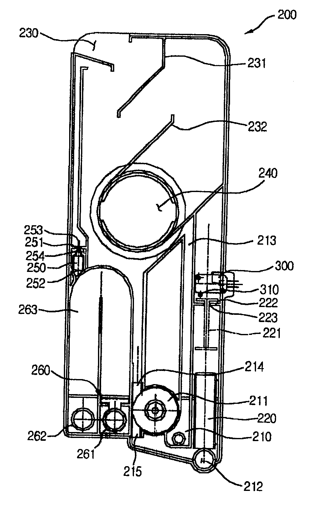
图4是本发明的空气制动器结构的断面图。Fig. 4 is a sectional view of the structure of the air brake of the present invention.
图5是本发明的洗碗机的过量给水防止结构的平面示意图。Fig. 5 is a schematic plan view of the overwatering prevention structure of the dishwasher of the present invention.
图6是流量检测装置的频率分布图。Fig. 6 is a frequency distribution diagram of the flow detection device.
图7是本发明洗碗机的过量给水防止方法的流程图。Fig. 7 is a flow chart of the method for preventing overwater supply of the dishwasher of the present invention.
100:洗碗机 110:桶 111:门100: Dishwasher 110: Bucket 111: Door
120:上部格栅 130:下部格栅 140:导水装置120: Upper grille 130: Lower grille 140: Water guiding device
150:上部喷管 160:下部喷管 170:贮槽150: Upper Nozzle 160: Lower Nozzle 170: Storage Tank
180:洗涤泵 190:电机 200:空气制动器180: Washing pump 190: Motor 200: Air brake
210:给水软管连接口 220:浮标 230:空气吸入口210: Water supply hose connection port 220: Buoy 230: Air suction port
240:桶连接口 250:虹吸防止单向阀 260:逆流防止单向阀240: Bucket connection port 250: Siphon prevention check valve 260: Backflow prevention check valve
300:微型开关 310:接触端子300: micro switch 310: contact terminal
具体实施方式 Detailed ways
如图2及图3所示,本发明的具有空气制动器结构的洗碗机100包括以下几个部分:形成外观,并且内部形成有餐具洗涤槽的桶110;形成于上述桶110的前面,用于开闭洗涤槽的门111;形成于上述桶110的底面中央部,用于储存洗涤水的贮槽170。As shown in Figures 2 and 3, the
详细的说,本发明还包括:紧贴于上述桶110的外侧面,将从给水装置中供给的洗涤水输送到上述贮槽170,并且具备有控制给水流量的装置的空气制动器200。In detail, the present invention also includes: an
另外,本发明还包括:与上述贮槽170连接,高压抽吸上述贮槽170中储存的洗涤水的洗涤泵180;紧贴于上述洗涤泵180的后面,驱动上述洗涤泵180的电机190。In addition, the present invention also includes: a washing pump 180 connected to the above-mentioned storage tank 170 for high-pressure suction of the washing water stored in the above-mentioned storage tank 170;
另外,本发明还包括:作为从上述洗涤泵180中抽吸的洗涤水流动的通道的导水装置140;设置于上述贮槽170的上面,并且形成于上述洗涤槽的底面,向上侧喷射洗涤水的下部喷管160;紧贴于上述导水装置140的上侧部,并从上述导水装置140向垂直方向延长形成后,位于上述洗涤槽的中央部的上部喷管150;形成于上述桶的顶部,向垂直下方喷射洗涤水的顶部喷管155。In addition, the present invention also includes: a water guiding device 140 as a channel for the flow of washing water sucked from the washing pump 180; it is arranged on the top of the above-mentioned storage tank 170, and is formed on the bottom surface of the above-mentioned washing tank, and sprays washing water to the upper side. The lower spray pipe 160 of water; it is closely attached to the upper side of the above-mentioned water guide device 140, and after being extended from the above-mentioned water guide device 140 to the vertical direction, the upper spray pipe 150 located in the central part of the above-mentioned washing tank; formed on the above-mentioned On the top of the tub, there is a top spray pipe 155 that sprays washing water vertically downward.
另外,本发明还包括:为了利用上述上部喷管150喷射的洗涤水洗涤餐具,而安装于上述上部喷管150的上侧部的上部格栅120;为了利用上述下部喷管160喷射的洗涤水洗涤餐具,而安装于上述下部喷管160的上侧部的下部格栅130。In addition, the present invention also includes: the upper grille 120 installed on the upper side of the upper nozzle 150 for washing dishes with the washing water sprayed from the upper nozzle 150; The dishes are washed, and the lower grill 130 is installed on the upper side of the lower spray pipe 160 .
详细的说,上述上部格栅120由上述桶110的内侧面设置的导轨(图中未示)所支撑,并且上述上部格栅可以向前后方向移动。In detail, the upper grill 120 is supported by guide rails (not shown) provided on the inner surface of the
下面,将对如上所述的本发明的洗碗机100的驱动过程进行说明。Next, the driving process of the
首先,用户先打开洗碗机100的门111,将上述上部格栅120及/或下部格栅130向洗涤槽外部拉出。随后,再将餐具放置在上述格栅120、130中。然后,关闭上述门111,并供给电源,从而使上述洗碗机驱动。First, the user opens the door 111 of the
另外,一旦电源供给至洗碗机100,开始进入洗涤阶段,从给水源中输送的洗涤水将经由上述空气制动器200,流入与上述空气制动器200用软管连接的上述贮槽170内部。在一定量的洗涤水流入贮槽内部后,上述电机190将驱动。然后,与上述电机190轴连接,并设置于上述洗涤泵180内部的叶轮(图中未示)将旋转,从而将洗涤水抽吸到上述下部喷管160及上述导水装置140。In addition, once power is supplied to the
另外,抽吸到上述导水装置140的洗涤水将最终流动到上述顶部喷管155和上述上部喷管150,喷射到洗涤槽内部。然后,利用上述喷射的洗涤水对上述格栅120、130内收容的餐具进行洗涤。In addition, the washing water sucked into the water guiding device 140 finally flows into the top nozzle 155 and the upper nozzle 150, and is sprayed into the washing tub. Then, the dishes accommodated in the grills 120 and 130 are washed with the sprayed washing water.
在这里,上述顶部喷管155将向垂直下方喷射洗涤水,上述上部喷管150则向垂直上方喷射洗涤水,从而可以对上述上部格栅120收容的餐具进行洗涤。Here, the top nozzle 155 sprays the washing water vertically downward, and the upper nozzle 150 sprays the washing water vertically upward, so that the tableware accommodated in the upper grill 120 can be washed.
另外,上述下部喷管160将向垂直上方喷射洗涤水,从而可以对上述下部格栅130收容的餐具进行洗涤。另外,在上述上部喷管150的底面也形成有喷射口,因此可以向上下两个方向喷射洗涤水,从而可以同时对上述下部格栅130收容的餐具的上侧面进行洗涤。In addition, the lower spray pipe 160 sprays washing water vertically upward, so that the dishes accommodated in the lower grill 130 can be washed. In addition, spray ports are also formed on the bottom surface of the upper spray pipe 150, so that washing water can be sprayed in both directions up and down, so that the upper side of the tableware accommodated in the lower grill 130 can be washed at the same time.
另外,一旦上述洗涤过程结束,集中到上述贮槽170的被污染的洗涤水将通过过滤器(图中未示)过滤出异物。上述过滤出异物的洗涤水将通过排水泵(图中未示)向上述洗碗机100外部排出。In addition, once the above-mentioned washing process is finished, the polluted washing water concentrated into the above-mentioned storage tank 170 will pass through a filter (not shown in the figure) to filter out foreign matter. The washing water from which the foreign matters are filtered out will be discharged to the outside of the
另外,一旦上述洗涤水排出到外部,会有干净的洗涤水通过流入口再次流入上述贮槽170,并同于上述洗涤阶段,通过上述喷射喷管150、160喷射出去。洗碗机将利用上述喷射的干净的洗涤水,对上述餐具进行清洗。In addition, once the washing water is discharged to the outside, clean washing water flows into the storage tank 170 again through the inlet, and is sprayed out through the spray nozzles 150 and 160 as in the washing stage. The dishwasher will use the sprayed clean washing water to clean the tableware.
一旦,上述清洗过程结束,将经过烘干过程,最终完成洗涤工作。Once the above cleaning process is over, it will go through the drying process and finally complete the washing work.
如图4所示,本发明的空气制动器200紧贴于桶110的外侧面。上述空气制动器200的作用是:将洗涤水输送到上述桶110的底面设置的贮槽170中。As shown in FIG. 4 , the
详细的说,上述空气制动器200包括以下几个部分:在上侧周边以一定大小开口,从而可以吸入室内空气的空气吸入口230;形成于底面一侧,用于供给餐具洗涤所需的水的给水软管连接口210;使通过上述给水软管连接口210流入的洗涤水流动的给水流路213。In detail, the above-mentioned
另外,还包括:位于上述给水流路213的末端,由于洗涤水的作用而旋转,从而检测流量的浮标测量计211;形成于上述空气制动器200的大概中央部,贯通上述桶110的侧面,从而使洗涤槽内部和上述空气吸入口230连通的洗涤槽空气吸入口240。In addition, it also includes: a
详细的说,上述给水流路213的形状大概为:从下部向上部垂直,并且在一定的高度上弯曲后,重新连接到下部的倒U字形状。此外,上述给水流路的末端设置有上述浮标测量计211。另外,使上述浮标测量计211的洗涤水流入口214向上方形成,从而可以利用上述洗涤水自由落下的力量,使上述浮标测量计211内部形成的叶轮旋转。In detail, the shape of the
如上所述,之所以要使给水流路213的形状呈倒U字形状,并使上述浮标测量计211的洗涤水流入口214向上方形成的理由是:一般而言,浮标测量计无法检测到0.5kg/cm2的低水压。因此,为了在水压很低的条件下,也能精密的检测出给水流量,本发明,即使有很少量的洗涤水流入,也可以根据上述流入的洗涤水的自重,使浮标测量计211的叶轮旋转。As mentioned above, the reason why the shape of the
更为详细的说,本发明还包括:为了防止洗涤槽内部产生的噪音通过上述空气吸入口230传播到外部,而从上述空气制动器200的上侧面延长一定长度,并以一定角度倾斜形成的第1空气导向壁231。另外,还包括:与上述洗涤槽空气吸入口240的外周面接触,并以一定角度倾斜形成,使从上述空气吸入口230到上述洗涤槽空气吸入口240的空气吸入流路大概呈S字形状的第2空气导向壁232。In more detail, the present invention also includes: in order to prevent the noise generated inside the washing tank from being transmitted to the outside through the
另外,本发明的空气制动器200还包括:洗涤水流出口215和贮槽给水连接口212。在这里,上述洗涤水流出口215的作用是:将经过上述洗涤水流入口214,使上述浮标测量计211内的叶轮旋转的洗涤水排出。而上述贮槽给水连接口212的作用是:作为使通过上述洗涤水流出口215的洗涤水流入上述贮槽170的入口。In addition, the
另外,本发明还包括:为了检测通过上述贮槽给水连接口212流入上述贮槽170内部的洗涤水的上升水位,而位于上述贮槽给水连接口212上端的浮标220;位于上述浮标220的上侧部,随着上述浮标220的上升或下降,一同上升或下降的浮标杆221;收容上述浮标220,并且可以使上述浮标220进行上下往返运动的浮标箱;形成于上述浮标杆221的上侧部,检测溢出水位的微型开关300。In addition, the present invention also includes: in order to detect the rising water level of the washing water flowing into the storage tank 170 through the water
另外,本发明还包括:为了使上述浮标杆221和上述浮标220间隔一定缝隙设置,而支撑上述浮标杆221的浮标杆支撑壁222;为了使上述浮标杆221贯通上述浮标杆支撑壁222上下运动,而形成于上述浮标杆支撑壁222的浮标杆贯通槽223。In addition, the present invention also includes: in order to arrange the above-mentioned
详细的说,如图4所示,上述浮标220设置于给水流路上,因此可以使紧贴于上述浮标220的下部的污染物被自动清理,从而可以防止错误的检测洗涤槽内的水位的现象。In detail, as shown in FIG. 4, the above-mentioned
另外,上述微型开关300的下端部形成有以一定的长度凸出后与上述浮标杆221的上端部接触的接触端子310。一旦洗涤槽内的水位达到限界线,上述浮标杆221的上端部将对上述接触端子310加压。一旦上述接触端子310被加压,使流入上述洗碗机100内部的洗涤水供给中断,或者驱动排水泵,从而可以防止供水过量引起的漏水事故。In addition, a
更为详细的说,供给到上述贮槽170内部的洗涤水将通过上述贮槽170内安装的加热器加热到一定温度。另外,为了防止上述加热的洗涤水中产生的水蒸气传递到微型开关300,引起错误驱动或电器性问题,并且为了能够容易的应对不同产品型号的水位限界线的变动,上述浮标220和上述浮标杆221是分离形成的。换句话说,在上述洗碗机正常驱动的情况下,上述浮标杆221可以堵住上述浮标杆贯通槽223,因此可以防止水蒸气传递到上述微型开关300。另外,由于上述浮标220的上侧面和上述浮标杆221的下侧端部间隔一定缝隙,因此可以根据洗碗机的容量,灵活的应对上述浮标220的规格变化。More specifically, the washing water supplied into the storage tank 170 is heated to a certain temperature by a heater installed in the storage tank 170 . In addition, in order to prevent the water vapor generated in the heated washing water from being transmitted to the
另外,本发明还包括:形成于上述空气制动器200的底面,使通过排水泵(图中未示)抽吸的被污染的洗涤水流入的贮槽排水连接口261;使流入上述贮槽排水连接口261的洗涤水流动的排水流路263;形成于上述排水流路的末端,与排水软管连接的排水软管连接口262。In addition, the present invention also includes: formed on the bottom surface of the above-mentioned
另外,本发明还包括:安装于上述排水流路263的上侧部,用于防止在排水中断后,洗涤水仍然继续通过上述排水流路263排出的虹吸现象的虹吸防止单向阀250;用于防止上述原本通过贮槽排水连接口261在上述排水流路263流动的洗涤水,由于排水中断而再次逆流到排水泵的现象的逆流防止单向阀260。In addition, the present invention also includes: a siphon
详细的说,上述虹吸防止单向阀250收容于具有一定大小的单向阀收容箱254内。另外,上述排水流路263的上侧部形成有具有一定大小的排水管连通孔252。另外,上述虹吸防止单向阀250收容箱254的上侧壁,形成有使凸出形成于上述虹吸防止单向阀250的单向阀支撑轴253贯通的支撑轴贯通槽251。Specifically, the siphon
更为详细的说,通过上述空气吸入口230流入的空气的一部分,将通过上述支撑轴贯通槽251流入上述单向阀收容箱254内。另外,流入上述单向阀收容箱254内的空气,将通过上述排水管连通孔252流入上述排水流路263内部。此外,上述虹吸防止单向阀250是由具有极易浮在水上的橡胶材质制成,并且其上部末端为尖细的形态,从而可以完全密闭上述支撑轴贯通槽251。More specifically, part of the air flowing in through the
下面,将对上述空气制动器200的工作过程及功能进行详细的说明。Next, the working process and functions of the
首先,不管上述洗碗机100驱动与否,通过上述空气吸入口230流入的空气,将通过上述洗涤槽空气吸入口240流入及流出。另外,一旦上述洗碗机100中有电源供给,水将通过给水软管连接口210流入,上述流入的水将通过上述给水流路213流动。另外,通过上述给水流路213流动的洗涤水将落下,从而使上述浮标测量计211内安装的叶轮旋转。另外,上述叶轮的旋转数的旋转频率将传送到洗碗机100的控制部中,从而可以判断出流入的给水量。First, regardless of whether the
另外,随着流入上述贮槽170内的洗涤水的水位上升,上述浮标220也将同时上升。此外,随着上述浮标220的上升,位于上述浮标220的上侧部的上述浮标杆221也将一同上升。一旦上述浮标杆221对上述微型开关300的接触端子310加压,上述微型开关300就能够检测到,并且将检测出的信号传送到上述洗碗机100的控制部,由于上述信号,给水工作将中断。In addition, as the water level of the washing water flowing into the storage tank 170 rises, the
另外,洗涤过程结束后,为了将含有食物渣滓的洗涤水排出,排水泵将驱动,由于排水泵的驱动,抽吸的洗涤水将通过上述贮槽排水连接口261流入。然后,洗涤水将通过上述排水流路263向上述排水软管连接口262流动,并最终通过与上述排水软管连接口262连接的排水软管排出到外部。In addition, after the washing process is finished, in order to discharge the washing water containing food residues, the drain pump will be driven. Due to the driving of the drain pump, the sucked washing water will flow in through the above-mentioned storage tank
另外,通过上述排水流路263流动的洗涤水中的一部分,将由于水压的作用,漏出到上述排水管连通孔252。然后,上述漏出的洗涤水将流入上述单向阀收容箱254,由于上述流入的洗涤水,上述虹吸防止单向阀250将上升。并且,在上述虹吸防止单向阀250上升时,形成为尖细的形状的虹吸防止单向阀的上侧部将堵住上述支撑轴贯通槽251。In addition, part of the washing water flowing through the
另外,排水中断后,在上述排水流路263上流动的洗涤水的量将减少,充满在上述单向阀收容箱254内的洗涤水将通过上述排水管连通孔252排出。并且,上述虹吸防止单向阀250也将一同下降,从而使上述支撑轴贯通槽251开口。另外,通过上述空气吸入口230流入的外部空气,将通过上述支撑轴贯通槽251、上述单向阀收容箱254,以及上述排水管连通孔252流入上述排水流路263。其结果,由于上述流入的空气,上述排水流路263中将充满空气,因此不会发生排水时的虹吸现象。In addition, after the drainage is interrupted, the amount of washing water flowing in the
如图5及图6所示,本发明的洗碗机的过量给水防止结构包括以下几个部分。浮标测量计211:上述浮标测量计的内部设置有由于顺着给水流路落下的洗涤水的作用而旋转的叶轮400;紧贴于上述叶轮400的旋转轴的带有磁性的磁铁500。As shown in Fig. 5 and Fig. 6, the overwater supply prevention structure of the dishwasher of the present invention includes the following parts. Float meter 211: the inside of the above-mentioned buoy meter is provided with an impeller 400 that rotates due to the action of washing water falling along the water supply flow path;
另外,还包括:用于检测通过上述磁铁500的旋转而产生的脉冲的霍尔传感器600;与上述霍尔传感器600连接,通过计算上述霍尔传感器600中传送的输出波形的频率,控制流量的微机700;与上述微机700连接,在输出规定的频率以上的波形的情况下,使洗涤水排出的排水泵800。In addition, it also includes: a
下面,将对上述过量给水防止装置进行详细的说明。Next, the above-mentioned overwatering prevention device will be described in detail.
首先,顺着给水流路流下的洗涤水将接触到上述叶轮400,从而使上述叶轮400旋转。随着上述叶轮400的旋转,紧贴于上述叶轮400的旋转轴的磁铁500也将一同旋转。另外,上述霍尔传感器600检测到上述磁铁500产生的磁场变化并产生脉冲P。并且,从上述霍尔传感器600中产生的脉冲P将传送到上述微机700,上述微机700则测定出上述脉冲P的频率。First, the wash water flowing down the water supply channel contacts the impeller 400 to rotate the impeller 400 . As the impeller 400 rotates, the
详细的说,上述脉冲P的频率即相当于上述叶轮400的旋转数,因此,上述微机700将对上述脉冲的频率和已经储存于上述微机中的脉冲的频率进行比较判断。更为详细的说,之所以要对上述脉冲的频率和储存于上述微机中的脉冲的频率进行比较判断的理由是:给水的流量是由上述叶轮400的旋转数测定的。In detail, the frequency of the pulse P corresponds to the number of rotations of the impeller 400, therefore, the
另外,如果传送到上述微机700的脉冲P的频率超过已储存于微机中的脉冲P的频率,则判断为过量给水,从而使连接于上述微机700的排水泵800驱动。因此,过量供给的洗涤水将通过上述排水泵800排出到外部,所以可以使洗涤槽内部维持正常水位。In addition, if the frequency of the pulse P sent to the
如图7所示,依据本发明的洗碗机的过量给水防止方法包含以下几个阶段构成:洗涤水流入阶段ST110;通过上述流入的洗涤水的作用,使上述叶轮旋转的阶段ST120;用于检测紧贴于上述叶轮的磁铁的霍尔传感器中输出脉冲的阶段ST130;在微机中比较判断上述输出的脉冲和储存的脉冲的阶段ST140;在储存的脉冲输出后,判断是否有脉冲继续输出的阶段ST160。As shown in FIG. 7 , the method for preventing excessive water supply of a dishwasher according to the present invention includes the following stages: a wash water inflow stage ST110; a stage ST120 in which the above-mentioned impeller is rotated by the action of the above-mentioned inflow of wash water; Stage ST130 of detecting the output pulse of the hall sensor attached to the magnet of the impeller; stage ST140 of comparing and judging the above-mentioned output pulse and the stored pulse in the microcomputer; after the stored pulse is output, it is judged whether there is a pulse to continue to output Stage ST160.
详细的说,在上述微机700中,对上述微机700中储存的脉冲的频率和输出的脉冲的频率进行比较判断后,如果输出的脉冲的频率与规定的脉冲的频率相同,则进入发出给水中断信号的阶段ST150。相反,如果输出的脉冲的频率小于规定的脉冲的频率,则继续进行给水。在这里,发出给水中断信号的阶段ST150可以编制为以下的程序:从上述微机中发出给水中断信号,关闭给水阀门,从而能够使洗涤水不能再通过给水阀门流入。In detail, in the
另外,在给水中断后,上述微机还将继续检测脉冲是否继续输出,如果不再输出脉冲,则正常的进入洗涤过程ST180。但是,如果即使从上述微机700中输出了给水中断信号,仍然有脉冲的继续输出,上述微机700将判断为给水阀门故障,从而进入发出排水泵驱动信号的强制排水阶段ST170。不但如此,上述微机700在发出上述排水泵驱动信号的同时,还可以发出能够使用户感知的报警音或者报警信息等报警信号。In addition, after the water supply is interrupted, the above-mentioned microcomputer will continue to detect whether the pulse continues to be output, and if the pulse is no longer output, it will normally enter the washing process ST180. However, if the
详细的说,上述排水泵800通过上述微机700的指令驱动后,可以将过量供给到洗涤槽内的洗涤水排出到外部,从而可以使洗涤槽内部始终维持正常水位。In detail, the
以上所述,仅是本发明的较佳实施例而已,并非对本发明作任何形式上的限制,凡是依据本发明的技术实质对以上实施例所作的任何简单修改、等同变化与修饰,均仍属于本发明技术方案的范围内。The above are only preferred embodiments of the present invention, and are not intended to limit the present invention in any form. Any simple modifications, equivalent changes and modifications made to the above embodiments according to the technical essence of the present invention still belong to within the scope of the technical solutions of the present invention.
发明的效果The effect of the invention
本发明的洗碗机的过量给水防止结构及其方法具有如下效果:由于能够防止洗涤槽内部的洗涤水过量给水的现象,因此可以确保洗碗机的安全性。The overwatering prevention structure and method of the dishwasher of the present invention have the effect of ensuring the safety of the dishwasher because it can prevent overwatering of the washing water inside the washing tub.
另外,当由于给水阀门损坏,而在达到正常水位后,仍有洗涤水供给的情况下,可以将过量供给的洗涤水强制排出,因此可以避免过量给水现象的发生。In addition, when the washing water is still supplied after reaching the normal water level due to damage to the water supply valve, the excess washing water can be forcibly discharged, thereby avoiding the occurrence of excessive water supply.
Claims (6)
Priority Applications (1)
| Application Number | Priority Date | Filing Date | Title |
|---|---|---|---|
| CNB2005100138775A CN100413455C (en) | 2005-06-23 | 2005-06-23 | Overwatering prevention structure and method for dishwasher |
Applications Claiming Priority (1)
| Application Number | Priority Date | Filing Date | Title |
|---|---|---|---|
| CNB2005100138775A CN100413455C (en) | 2005-06-23 | 2005-06-23 | Overwatering prevention structure and method for dishwasher |
Publications (2)
| Publication Number | Publication Date |
|---|---|
| CN1883363A CN1883363A (en) | 2006-12-27 |
| CN100413455C true CN100413455C (en) | 2008-08-27 |
Family
ID=37581762
Family Applications (1)
| Application Number | Title | Priority Date | Filing Date |
|---|---|---|---|
| CNB2005100138775A Expired - Fee Related CN100413455C (en) | 2005-06-23 | 2005-06-23 | Overwatering prevention structure and method for dishwasher |
Country Status (1)
| Country | Link |
|---|---|
| CN (1) | CN100413455C (en) |
Families Citing this family (8)
| Publication number | Priority date | Publication date | Assignee | Title |
|---|---|---|---|---|
| SE533765C2 (en) * | 2009-05-05 | 2010-12-28 | Tetra Laval Holdings & Finance | Method of controlling a process |
| DE102009027690A1 (en) | 2009-07-14 | 2011-01-20 | BSH Bosch und Siemens Hausgeräte GmbH | Water-conducting household appliance |
| DE102010027756A1 (en) | 2010-04-14 | 2011-10-20 | BSH Bosch und Siemens Hausgeräte GmbH | Dishwasher with fault detection |
| CN102508023B (en) * | 2011-11-14 | 2016-12-07 | 美的集团股份有限公司 | The signal deteching circuit of shunt valve of dishwasher and frequency detecting method |
| CN104615162B (en) * | 2015-02-03 | 2017-07-21 | 安康学院 | A kind of water level control warning system |
| CN105266735B (en) * | 2015-10-09 | 2018-05-01 | 佛山市顺德区美的洗涤电器制造有限公司 | Dish-washing machine and its control method |
| CN107374537B (en) * | 2017-07-31 | 2021-04-20 | 佛山市顺德区美的洗涤电器制造有限公司 | Dishwasher control method and dishwasher |
| CN109730603B (en) * | 2019-01-16 | 2020-11-06 | 佛山市云米电器科技有限公司 | Dish washing machine and control method thereof |
Citations (10)
| Publication number | Priority date | Publication date | Assignee | Title |
|---|---|---|---|---|
| JPH05154085A (en) * | 1991-12-03 | 1993-06-22 | Mitsubishi Electric Corp | Overflow preventer for dish washer |
| JPH09108162A (en) * | 1995-10-17 | 1997-04-28 | Matsushita Electric Ind Co Ltd | dishwasher |
| CN2349978Y (en) * | 1997-06-20 | 1999-11-24 | 南京飞龙洗碗机有限公司 | Water level controller for dish washer |
| CN2363271Y (en) * | 1999-03-16 | 2000-02-09 | 杨钟汤 | Water meter flow reading device |
| CN2423856Y (en) * | 2000-04-21 | 2001-03-21 | 无锡小天鹅梅洛尼洗碗机有限公司 | Water level controller of dish-washing machine |
| JP2001346748A (en) * | 2000-06-08 | 2001-12-18 | Mitsubishi Electric Corp | Dishwasher |
| CN2469884Y (en) * | 2001-03-20 | 2002-01-09 | 深圳市安吉尔厨具科技有限公司 | A composite water level switch |
| CN2469883Y (en) * | 2001-01-04 | 2002-01-09 | 深圳市安吉尔厨具科技有限公司 | Dishwasher overflow device |
| JP2003047585A (en) * | 2001-08-07 | 2003-02-18 | Matsushita Electric Ind Co Ltd | dishwasher |
| JP2004283431A (en) * | 2003-03-24 | 2004-10-14 | Toto Ltd | Dish washer/dryer |
-
2005
- 2005-06-23 CN CNB2005100138775A patent/CN100413455C/en not_active Expired - Fee Related
Patent Citations (10)
| Publication number | Priority date | Publication date | Assignee | Title |
|---|---|---|---|---|
| JPH05154085A (en) * | 1991-12-03 | 1993-06-22 | Mitsubishi Electric Corp | Overflow preventer for dish washer |
| JPH09108162A (en) * | 1995-10-17 | 1997-04-28 | Matsushita Electric Ind Co Ltd | dishwasher |
| CN2349978Y (en) * | 1997-06-20 | 1999-11-24 | 南京飞龙洗碗机有限公司 | Water level controller for dish washer |
| CN2363271Y (en) * | 1999-03-16 | 2000-02-09 | 杨钟汤 | Water meter flow reading device |
| CN2423856Y (en) * | 2000-04-21 | 2001-03-21 | 无锡小天鹅梅洛尼洗碗机有限公司 | Water level controller of dish-washing machine |
| JP2001346748A (en) * | 2000-06-08 | 2001-12-18 | Mitsubishi Electric Corp | Dishwasher |
| CN2469883Y (en) * | 2001-01-04 | 2002-01-09 | 深圳市安吉尔厨具科技有限公司 | Dishwasher overflow device |
| CN2469884Y (en) * | 2001-03-20 | 2002-01-09 | 深圳市安吉尔厨具科技有限公司 | A composite water level switch |
| JP2003047585A (en) * | 2001-08-07 | 2003-02-18 | Matsushita Electric Ind Co Ltd | dishwasher |
| JP2004283431A (en) * | 2003-03-24 | 2004-10-14 | Toto Ltd | Dish washer/dryer |
Also Published As
| Publication number | Publication date |
|---|---|
| CN1883363A (en) | 2006-12-27 |
Similar Documents
| Publication | Publication Date | Title |
|---|---|---|
| KR101054148B1 (en) | Air brake in dishwasher | |
| CN102573595B (en) | Washing machines, such as dishwashers or washing machines, and methods of operating washing machines | |
| CN106061348B (en) | Dish-washing machine and the method for controlling the dish-washing machine | |
| KR20050102457A (en) | An overflow preventing structure and method of a dish washer | |
| KR20110046175A (en) | Dishwasher having filter clogging detection means and control method thereof | |
| CN100413455C (en) | Overwatering prevention structure and method for dishwasher | |
| KR101266870B1 (en) | Dish Washer | |
| KR101054154B1 (en) | Air brake in dishwasher | |
| KR101052974B1 (en) | Air brake structure of dishwasher | |
| KR20190004151A (en) | Controlling Method of Dish Washer | |
| JP2008183276A (en) | dishwasher | |
| KR101070063B1 (en) | An air brake including a water level sensing apparatus of a dish washer | |
| KR101135855B1 (en) | A self drainage preventing structure of a dish washer | |
| KR101054104B1 (en) | Air brake structure of dishwasher | |
| CN100431468C (en) | Air brake of bowl washer | |
| KR101065697B1 (en) | Air brake assembly of dishwasher and water supply control method using the same | |
| KR101054183B1 (en) | Air brake structure of dishwasher | |
| KR101307590B1 (en) | A dish washer and method of controlling the same | |
| JP4347232B2 (en) | Dishwasher | |
| KR100717471B1 (en) | Water supply of dishwasher | |
| KR100693518B1 (en) | Foam backflow prevention structure of dishwasher sump | |
| CN100413453C (en) | Dishwasher tank structure | |
| KR101138108B1 (en) | A self drainage sensing structure of dish washer | |
| CN100502757C (en) | dishwasher | |
| CN100431471C (en) | Air brake structure of dish washer |
Legal Events
| Date | Code | Title | Description |
|---|---|---|---|
| C06 | Publication | ||
| PB01 | Publication | ||
| C10 | Entry into substantive examination | ||
| SE01 | Entry into force of request for substantive examination | ||
| C14 | Grant of patent or utility model | ||
| GR01 | Patent grant | ||
| C17 | Cessation of patent right | ||
| CF01 | Termination of patent right due to non-payment of annual fee |
Granted publication date: 20080827 Termination date: 20110623 |