CN100413458C - insert support system - Google Patents
insert support system Download PDFInfo
- Publication number
- CN100413458C CN100413458C CNB200480032338XA CN200480032338A CN100413458C CN 100413458 C CN100413458 C CN 100413458C CN B200480032338X A CNB200480032338X A CN B200480032338XA CN 200480032338 A CN200480032338 A CN 200480032338A CN 100413458 C CN100413458 C CN 100413458C
- Authority
- CN
- China
- Prior art keywords
- path
- route
- image
- unit
- vbs
- Prior art date
- Legal status (The legal status is an assumption and is not a legal conclusion. Google has not performed a legal analysis and makes no representation as to the accuracy of the status listed.)
- Expired - Lifetime
Links
Images






Classifications
-
- A—HUMAN NECESSITIES
- A61—MEDICAL OR VETERINARY SCIENCE; HYGIENE
- A61B—DIAGNOSIS; SURGERY; IDENTIFICATION
- A61B1/00—Instruments for performing medical examinations of the interior of cavities or tubes of the body by visual or photographical inspection, e.g. endoscopes; Illuminating arrangements therefor
- A61B1/00002—Operational features of endoscopes
- A61B1/00004—Operational features of endoscopes characterised by electronic signal processing
- A61B1/00009—Operational features of endoscopes characterised by electronic signal processing of image signals during a use of endoscope
-
- A—HUMAN NECESSITIES
- A61—MEDICAL OR VETERINARY SCIENCE; HYGIENE
- A61B—DIAGNOSIS; SURGERY; IDENTIFICATION
- A61B34/00—Computer-aided surgery; Manipulators or robots specially adapted for use in surgery
- A61B34/10—Computer-aided planning, simulation or modelling of surgical operations
-
- A—HUMAN NECESSITIES
- A61—MEDICAL OR VETERINARY SCIENCE; HYGIENE
- A61B—DIAGNOSIS; SURGERY; IDENTIFICATION
- A61B10/00—Instruments for taking body samples for diagnostic purposes; Other methods or instruments for diagnosis, e.g. for vaccination diagnosis, sex determination or ovulation-period determination; Throat striking implements
- A61B10/02—Instruments for taking cell samples or for biopsy
-
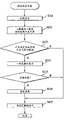
- A—HUMAN NECESSITIES
- A61—MEDICAL OR VETERINARY SCIENCE; HYGIENE
- A61B—DIAGNOSIS; SURGERY; IDENTIFICATION
- A61B34/00—Computer-aided surgery; Manipulators or robots specially adapted for use in surgery
- A61B34/10—Computer-aided planning, simulation or modelling of surgical operations
- A61B2034/101—Computer-aided simulation of surgical operations
- A61B2034/105—Modelling of the patient, e.g. for ligaments or bones
-
- A—HUMAN NECESSITIES
- A61—MEDICAL OR VETERINARY SCIENCE; HYGIENE
- A61B—DIAGNOSIS; SURGERY; IDENTIFICATION
- A61B34/00—Computer-aided surgery; Manipulators or robots specially adapted for use in surgery
- A61B34/20—Surgical navigation systems; Devices for tracking or guiding surgical instruments, e.g. for frameless stereotaxis
- A61B2034/2046—Tracking techniques
- A61B2034/2065—Tracking using image or pattern recognition
-
- A—HUMAN NECESSITIES
- A61—MEDICAL OR VETERINARY SCIENCE; HYGIENE
- A61B—DIAGNOSIS; SURGERY; IDENTIFICATION
- A61B34/00—Computer-aided surgery; Manipulators or robots specially adapted for use in surgery
- A61B34/30—Surgical robots
- A61B2034/301—Surgical robots for introducing or steering flexible instruments inserted into the body, e.g. catheters or endoscopes
-
- A—HUMAN NECESSITIES
- A61—MEDICAL OR VETERINARY SCIENCE; HYGIENE
- A61B—DIAGNOSIS; SURGERY; IDENTIFICATION
- A61B34/00—Computer-aided surgery; Manipulators or robots specially adapted for use in surgery
- A61B34/25—User interfaces for surgical systems
Landscapes
- Health & Medical Sciences (AREA)
- Life Sciences & Earth Sciences (AREA)
- Surgery (AREA)
- Engineering & Computer Science (AREA)
- Animal Behavior & Ethology (AREA)
- Veterinary Medicine (AREA)
- Biomedical Technology (AREA)
- Heart & Thoracic Surgery (AREA)
- Medical Informatics (AREA)
- Molecular Biology (AREA)
- Nuclear Medicine, Radiotherapy & Molecular Imaging (AREA)
- General Health & Medical Sciences (AREA)
- Public Health (AREA)
- Robotics (AREA)
- Signal Processing (AREA)
- Physics & Mathematics (AREA)
- Biophysics (AREA)
- Optics & Photonics (AREA)
- Pathology (AREA)
- Radiology & Medical Imaging (AREA)
- Apparatus For Radiation Diagnosis (AREA)
- Endoscopes (AREA)
Abstract
Description
技术领域 technical field
本发明涉及支持内窥镜的插入的插入支持系统。The present invention relates to an insertion support system for supporting insertion of an endoscope.
背景技术 Background technique
近年来广泛地进行基于图像的诊断,例如,利用X射线CT(ComputedTomography,计算机断层摄影)装置等拍摄被检体的断层像,从而在被检体内得到三维图像数据,使用该三维图像数据进行目标部位的诊断。In recent years, image-based diagnosis has been widely carried out. For example, X-ray CT (Computed Tomography, computerized tomography) equipment and the like are used to take tomographic images of the subject, thereby obtaining three-dimensional image data in the subject, and using the three-dimensional image data to perform target site diagnosis.
在CT装置中,通过连续地旋转X射线照射/检测、并在体轴方向上连续输送被检体,可以对被检体的三维区域进行螺旋状的连续扫描(螺旋扫描:helical scan),根据三维区域的连续切片的断层像作成三维图像。In the CT apparatus, by continuously rotating X-ray irradiation/detection and continuously transporting the subject in the direction of the body axis, it is possible to perform helical continuous scanning (helical scan) on the three-dimensional area of the subject, according to A three-dimensional image is created by sequentially sliced tomographic images of the three-dimensional region.
作为这种三维图像之一有肺的支气管的三维图像。支气管的三维图像例如用来三维地掌握被怀疑为肺癌等的异常部的位置。并且,为了通过活检确认异常部,插入支气管内窥镜并从末端部伸出活检针或活检钳等,采集组织的样本(sample)。As one of such three-dimensional images there is a three-dimensional image of the bronchi of the lungs. The three-dimensional image of the bronchi is used, for example, to three-dimensionally grasp the position of an abnormality suspected to be lung cancer or the like. Then, in order to confirm the abnormal part by biopsy, a bronchoscope is inserted, a biopsy needle, biopsy forceps, etc. are extended from the distal end, and a tissue sample is collected.
在像支气管那样具有多个阶段的分支的体内管路中,异常部的位置接近分支的末梢时,难以使内窥镜的末端在短时间内准确到达目标部位,因此例如在日本特开2000-135215号公报等中提出了如下的装置:根据被检体的三维区域的图像数据作成所述被检体内的管路的三维像,在所述三维像上求出沿着所述管路到达目标点的路径,根据所述图像数据作成沿着所述路径的所述管路的虚拟内窥像,显示所述虚拟内窥像,从而把支气管内窥镜导向目标部位。In a body pipeline with multi-stage branches like bronchi, when the position of the abnormal part is close to the end of the branch, it is difficult to make the tip of the endoscope reach the target site accurately in a short time. Therefore, for example, in JP-A 2000- No. 135215 and the like propose a device that creates a three-dimensional image of a pipeline in the subject based on image data of a three-dimensional region of the subject, and obtains a target along the pipeline on the three-dimensional image. A path of dots is created, based on the image data, a virtual endoscopic image of the pipeline along the path is created, and the virtual endoscopic image is displayed, thereby guiding the bronchoscope to a target site.
但是,作为目标部位的活体组织一般存在扩展性,所以即使指定活检时的活检位置,也不能唯一地确定到达该活检位置的插入路径,而可能设定多个插入路径,但在现有的装置中,存在不能从多个插入路径中确定进行插入支持时的最佳插入路径的问题。However, living tissue as a target site generally has expansibility, so even if a biopsy site is specified at the time of biopsy, the insertion route to the biopsy site cannot be uniquely determined, and multiple insertion routes may be set, but in existing devices In , there is a problem that the optimal insertion path cannot be determined from multiple insertion paths when performing insertion support.
本发明就是鉴于上述情况而提出的,其目的在于,提供能够在多个插入路径中验证进行插入支持时的最佳插入路径的插入支持系统。The present invention has been made in view of the above circumstances, and an object of the present invention is to provide an insertion support system capable of verifying an optimal insertion path when performing insertion support among a plurality of insertion paths.
发明内容 Contents of the invention
本发明的插入支持系统构成为具有:虚拟图像生成单元,其根据被检体的三维区域的图像数据,生成所述被检体内的体腔路的虚拟图像;路径始点设定单元,其设定内窥镜到达所述被检体内的体腔路的插入路径的始点;关注区域设定单元,其设定所述被检体内的关注部位的区域;路径提取单元,其提取从所述始点至所述关注部位的区域的多个所述插入路径;以及路径验证单元,其验证由所述路径提取单元提取出的多个所述插入路径。The insertion support system of the present invention is configured to include: a virtual image generating unit that generates a virtual image of a body cavity path in the subject based on image data of a three-dimensional region of the subject; The speculum arrives at a starting point of an insertion route of a body cavity path in the subject; an attention region setting unit that sets a region of a site of interest in the subject; a route extraction unit that extracts a path from the starting point to the a plurality of the insertion routes of the region of interest; and a route verification unit that verifies the plurality of the insertion routes extracted by the route extraction unit.
本发明的插入支持系统具有能够从多个插入路径中验证进行插入支持时的最佳插入路径的效果。The insertion support system of the present invention has the effect of being able to verify an optimal insertion path for insertion support from among a plurality of insertion paths.
附图说明 Description of drawings
图1是表示本发明的实施例1的支气管插入支持系统的结构的结构图。FIG. 1 is a structural diagram showing the structure of a bronchial insertion support system according to
图2是表示图1的路径设定部的功能结构的方框图。FIG. 2 is a block diagram showing a functional configuration of a route setting unit in FIG. 1 .
图3是表示通过图1的插入支持装置进行的插入支持准备处理的流程的流程图。3 is a flowchart showing the flow of insertion support preparation processing performed by the insertion support device of FIG. 1 .
图4是表示在图3的处理中展开的路径设定画面的第1图。FIG. 4 is a first diagram showing a route setting screen developed in the process of FIG. 3 .
图5是表示在图3的处理中展开的路径设定画面的第2图。FIG. 5 is a second diagram showing a route setting screen developed in the process of FIG. 3 .
图6是表示在图3的处理中展开的路径设定画面的第3图。FIG. 6 is a third diagram showing a route setting screen developed in the process of FIG. 3 .
图7是表示在图3的处理中展开的路径设定画面的第4图。FIG. 7 is a fourth diagram showing a route setting screen developed in the process of FIG. 3 .
图8是表示在图3的处理中展开的路径设定画面的第5图。FIG. 8 is a fifth diagram showing a route setting screen developed in the process of FIG. 3 .
图9是表示图3的路径设定处理的流程的流程图。FIG. 9 is a flowchart showing the flow of route setting processing in FIG. 3 .
图10是说明图9的处理的第1图。FIG. 10 is a first diagram illustrating the processing of FIG. 9 .
图11是说明图9的处理的第2图。FIG. 11 is a second diagram illustrating the processing of FIG. 9 .
图12是表示在图9的处理中展开的路径设定画面的第1图。FIG. 12 is a first diagram showing a route setting screen developed in the process of FIG. 9 .
图13是说明图9的处理的第3图。FIG. 13 is a third diagram illustrating the processing of FIG. 9 .
图14是表示在图9的处理中展开的路径设定画面的第2图。FIG. 14 is a second diagram showing a route setting screen developed in the process of FIG. 9 .
图15是说明图9的处理的第4图。FIG. 15 is a fourth diagram illustrating the processing of FIG. 9 .
图16是表示在图9的处理中展开的路径设定画面的第3图。FIG. 16 is a third diagram showing a route setting screen developed in the process of FIG. 9 .
图17是表示基于图2的路径设定部的路径验证功能所生成的MPR图像的路径验证窗口的图。17 is a diagram showing a route verification window of an MPR image generated based on a route verification function of the route setting unit in FIG. 2 .
图18是说明图17的路径验证窗口的作用的第1图。FIG. 18 is a first diagram illustrating the function of the route verification window in FIG. 17. FIG.
图19是说明图17的路径验证窗口的作用的第2图。FIG. 19 is a second diagram illustrating the function of the route verification window of FIG. 17. FIG.
图20是说明图17的路径验证窗口的作用的第3图。FIG. 20 is a third diagram illustrating the function of the route verification window in FIG. 17. FIG.
图21是说明图17的路径验证窗口的作用的第4图。FIG. 21 is a fourth diagram illustrating the function of the route verification window of FIG. 17. FIG.
图22是说明图17的路径验证窗口的作用的第5图。FIG. 22 is a fifth diagram illustrating the function of the route verification window of FIG. 17. FIG.
图23是说明图17的路径验证窗口的作用的第6图。FIG. 23 is a sixth diagram illustrating the function of the route verification window of FIG. 17. FIG.
图24是说明图17的路径验证窗口的作用的第7图。FIG. 24 is a seventh diagram illustrating the function of the route verification window of FIG. 17. FIG.
图25是说明图17的路径验证窗口的作用的第8图。FIG. 25 is an eighth diagram illustrating the function of the route verification window of FIG. 17. FIG.
图26是说明图17的路径验证窗口的作用的第9图。FIG. 26 is a ninth diagram illustrating the function of the route verification window of FIG. 17. FIG.
图27是说明图26的VBS显示框的第1图。FIG. 27 is a first diagram illustrating the VBS display frame of FIG. 26. FIG.
图28是说明图26的VBS显示框的第2图。Fig. 28 is a second diagram illustrating the VBS display frame of Fig. 26 .
图29是说明图26的VBS显示框的第3图。Fig. 29 is a third diagram illustrating the VBS display frame of Fig. 26 .
图30是说明图26的VBS显示框的变形例的图。FIG. 30 is a diagram illustrating a modified example of the VBS display frame shown in FIG. 26 .
图31是表示基于图2的路径设定部的路径验证功能所生成的细线化模型图像的路径验证窗口的图。31 is a diagram showing a route verification window of a line-thinned model image generated by a route verification function of the route setting unit in FIG. 2 .
图32是说明图31的细线化模型图像的图。FIG. 32 is a diagram illustrating the thinned model image of FIG. 31 .
图33是说明图31的路径验证窗口的作用的第1图。Fig. 33 is a first diagram for explaining the function of the route verification window in Fig. 31 .
图34是说明图31的路径验证窗口的作用的第2图。Fig. 34 is a second diagram illustrating the function of the route verification window of Fig. 31 .
图35是说明图31的路径验证窗口的作用的第3图。FIG. 35 is a third diagram illustrating the function of the route verification window in FIG. 31. FIG.
图36是说明图31的路径验证窗口的作用的第4图。FIG. 36 is a fourth diagram illustrating the function of the route verification window in FIG. 31. FIG.
图37是说明图31的路径验证窗口的作用的第5图。FIG. 37 is a fifth diagram illustrating the function of the route verification window of FIG. 31. FIG.
图38是说明图31的路径验证窗口的作用的第6图。FIG. 38 is a sixth diagram illustrating the function of the route verification window of FIG. 31. FIG.
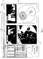
图39是表示在图9的处理中展开的插入支持画面的图。Fig. 39 is a diagram showing an insertion support screen developed in the process of Fig. 9 .
图40是表示基于本发明的实施例2的路径验证功能的路径设定仿真处理的流程的流程图。40 is a flowchart showing the flow of route setting simulation processing by the route verification function according to the second embodiment of the present invention.
图41是说明图40的路径设定仿真处理的第1图。Fig. 41 is a first diagram for explaining the route setting simulation process of Fig. 40 .
图42是说明图40的路径设定仿真处理的第2图。FIG. 42 is a second diagram illustrating the route setting simulation process of FIG. 40 .
图43是说明图40的路径设定仿真处理的第3图。FIG. 43 is a third diagram illustrating the route setting simulation process of FIG. 40 .
图44是说明图40的路径设定仿真处理的第4图。FIG. 44 is a fourth diagram illustrating the route setting simulation process of FIG. 40 .
具体实施方式 Detailed ways
以下,参照附图说明本发明的实施例。Hereinafter, embodiments of the present invention will be described with reference to the drawings.
(实施例1)(Example 1)
如图1所示,本实施例的支气管插入支持系统1由支气管内窥镜装置3和插入支持装置5构成。As shown in FIG. 1 , a bronchial
插入支持装置5根据CT图像数据生成支气管内部的虚拟的内窥像(以下表述为VBS图像),并且将通过支气管内窥镜装置3得到的内窥镜图像(以下表述为实时图像)和VBS图像合成,显示在监视器6上,进行支气管内窥镜装置3向支气管的插入支持。The
并且,虽然未图示,但支气管内窥镜装置3由具有摄像单元的支气管镜、向支气管镜提供照明光的光源、以及对来自支气管镜的摄像信号进行信号处理的摄像机控制单元等构成,把支气管镜插入到患者体内的支气管中,对支气管内部进行拍摄,对支气管末端的目标组织进行活检,并且将实时图像和VBS图像合成而显示在监视器7上。In addition, although not shown in the figure, the
监视器7设有由触摸屏构成的输入部8,能够一面进行插入操作一面容易地操作由触摸屏构成的输入部8。The
插入支持装置5由以下部分构成:CT图像数据取入部11,其通过例如MO(Magnetic Optical disk,磁光盘)装置或DVD(Digital VersatileDisk,数字通用光盘)装置等移动型的存储介质,取入由拍摄患者的X射线断层像的未图示的公知的CT装置生成的三维图像数据;CT图像数据存储部12,其存储通过CT图像数据取入部11取入的CT图像数据;MPR图像生成部13,其根据存储在CT图像数据存储部12中的CT图像数据,生成MPR图像(多断面重建图像:冠状位像、轴位像、矢状位像);路径设定部14,其生成具有由MPR图像生成部生成的MPR图像的后述的路径设定画面,设定支气管内窥镜装置3到达支气管的支持路径(以下简记为路径);作为虚拟图像生成单元的VBS图像生成部15,其根据存储在CT图像数据存储部12中的CT图像数据,以帧为单位生成由路径设定部14设定的路径的连续的VBS图像VBS图像存储部16,其存储由VBS图像生成部15生成的VBS图像;图像处理部17,其输入来自支气管内窥镜装置3的摄像信号和来自输入部8的输入信号,生成由实时图像、VBS图像以及多个缩略VBS图像构成的后述的插入支持画面;图像显示控制部18,其在监视器6上显示由路径设定部14生成的路径设定画面和由图像处理部17生成的插入支持画面;以及输入装置19,其由向路径设定部14输入设定信息的键盘和指示设备构成。
支气管内窥镜装置3从插入支持装置5的图像处理部17接收VBS图像和缩略VBS图像,与实时图像合成,在监视器7上显示与由插入支持装置5显示于监视器6上的插入支持画面同等的画面,并且把来自监视器7的由触摸屏构成的输入部8的输入信息输出给插入支持装置5的图像处理部17。The
另外,CT图像数据存储部12和VBS图像存储部16也可以通过一个硬盘构成,且MPR图像生成部13、路径设定部14、VBS图像生成部15以及图像处理部17可以由一个运算处理电路构成。并且,CT图像数据取入部11通过MO或DVD等移动型的存储介质取入CT图像数据,但在CT装置或保存CT图像数据的内部服务器连接在内部LAN上时,也可以通过可连接该内部LAN的接口电路构成CT图像数据取入部11,通过内部LAN取入CT图像数据。In addition, the CT image
如图2所示,路径设定部14构成为具有:作为路径始点设定单元的路径始点设定功能14a,其设定支气管插入的插入始点;作为关注区域设定单元的关注区域设定功能14b,其设定作为支气管插入的插入终点的关注区域;作为路径提取单元的路径提取功能14c,其提取从插入始点到插入终点的插入路径;以及作为路径验证单元的路径验证功能14d,其进行所提取的插入路径的验证。关于这些功能的具体情况将在后面叙述。As shown in FIG. 2 , the
说明这样构成的本实施方式的作用。The operation of this embodiment configured in this way will be described.
如图3所示,在利用支气管内窥镜装置3进行观察/处置之前,插入支持装置5在步骤S1中通过CT图像数据取入部11取入由CT装置生成的患者的CT图像数据,在步骤S2中把所取入的CT图像数据存储在CT图像数据存储部12中。As shown in FIG. 3, before using the
在步骤S3中,通过路径设定部14在监视器6上显示图4所示的路径设定画面21,在路径设定画面21上的患者信息标签画面22中选择患者信息。通过该选择,在步骤S4中,生成所选择的患者的例如由3个不同的多断面重建图像构成的作为MPR图像的冠状位像23a、轴位图像23b、矢状位像23c(以下也简记为MPR图像23),在步骤S5中,在路径设定画面21上显示该冠状位像23a、轴位像23b、矢状位像23c。在路径设定画面21中设有显示VBS图像的VBS图像显示区域23d。In step S3, the
另外,患者信息标签画面22中的患者信息的选择通过利用输入装置19输入识别患者的患者ID来进行。In addition, selection of patient information on the patient
然后,在步骤S6中,通过输入装置19选择路径设定画面21上的路径设定标签24(参照图4)时,图5所示的路径设定标签画面25显示在路径设定画面21上,进行后述的路径设定处理,设定支气管镜在支气管内的插入支持的路径。Then, in step S6, when the route setting tab 24 (referring to FIG. 4 ) on the
在设定了插入支持的路径时,在步骤S7中,通过VBS图像生成部15以帧为单位生成所设定的所有路径的连续的VBS图像,在步骤S8中,把所生成的VBS图像存储在VBS图像存储部16中。When the path of insertion support is set, in step S7, the continuous VBS image of all the paths set is generated by the VBS
通过上述的步骤S1~S8的处理,完成使用支气管镜进行观察/处置时的通过插入支持装置5进行的插入支持的准备。Through the processing of steps S1 to S8 described above, preparations for insertion support by the
此处,使用图6~图9说明上述步骤S6的路径设定处理。Here, the route setting process of step S6 described above will be described using FIGS. 6 to 9 .
在路径设定画面21中选择了路径搜索按钮时,开始步骤S6的路径设定处理。具体讲,通过路径设定部14的路径始点设定功能14a,在路径设定画面21上显示图6所示的促使输入路径始点的始点输入指示窗口31,在路径设定画面21上使用光标30在MPR图像23中的一个断层像上设定始点71。设定始点71后,在MPR图像23的其它两个断层像上也在对应的位置处设定始点71,并且在VBS图像显示区域23d中显示始点71的VBS图像,在路径设定画面21上显示图7所示的促使设定作为路径终点的活检区域72的活检区域输入指示窗口32。When the route search button is selected on the
然后,利用路径设定部14的关注区域设定功能14b,在该图6的路径设定画面21上,使用光标30在MPR图像23中的任意两个断层像上二维地描画而设定作为关注区域的活检区域72。此时设定的活检区域72的数量不限于一个,而可以指定多个,在图7中示出了指定两个活检区域72a、72b的状态。Then, using the
并且,在活检区域72的设定结束后,利用路径设定部14的路径提取功能14c,在路径设定画面21上显示图8所示的设定每一个活检区域72的待搜索的路径数量的路径数量设定窗口33。通过设定每一个活检区域72的待搜索的路径数量,搜索出多个引导对象的到达活检区域72的接近路径。And, after the setting of the
即,通过图6~图8设定始点、活检区域72以及搜索路径数量后,按照图9的处理,利用路径提取功能14c搜索路径。That is, after setting the starting point, the
即,如图9所示,在步骤S11中,检测所设定的活检区域72的数量,在步骤S12中,读入搜索路径数量n,在步骤S13中,读入始点71的位置。That is, as shown in FIG. 9, in step S11, the number of
并且,在步骤S14中,提取活检区域72的重心位置,在步骤S15中,把表示以重心位置为中心的球的半径的r设为初始值r0后,在步骤S16中,把半径r的球内部指定为搜索区域。And, in step S14, extract the position of the center of gravity of the
在步骤S17中,判断搜索区域内是否有支气管,在有支气管时,在步骤S18中,确定以其位置作为终点的路径候选。In step S17, it is judged whether there is a bronchus in the search area, and if there is a bronchus, in step S18, a route candidate with its position as the end point is determined.
在确定了路径候选后,在步骤S19中,判断所确定的路径候选是否已经登记,在未登记时,在步骤S20中,生成基于从始点到终点的分支点名称的路径名称,登记为支持路径。After the path candidate is determined, in step S19, it is judged whether the determined path candidate has been registered, and if not registered, in step S20, a path name based on the name of the branch point from the start point to the end point is generated and registered as a support path .
并且,在步骤S21中,判断所登记的路径数量是否小于在步骤S12中读入的路径数量n。And, in step S21, it is judged whether the number of registered routes is smaller than the number n of routes read in in step S12.
另外,在步骤S17中判断为搜索区域内没有支气管时、在步骤S19中所确定的路径候选已经登记时,或者在步骤S21中登记的路径数量小于路径数量n时,在步骤S22中,把r设为r+Δr,扩大搜索区域,返回步骤S16。In addition, when it is determined in step S17 that there is no bronchus in the search area, when the path candidates determined in step S19 have been registered, or when the number of paths registered in step S21 is less than the number n of paths, in step S22, r Set to r+Δr, expand the search area, and return to step S16.
在已登记的路径数量达到在步骤S12中读入的路径数量n时,在步骤S23中,判断是否已搜索所设定的所有活检区域,如果已搜索所有活检区域则结束处理,在还有未搜索的活检区域时,在步骤S24中提取下一个活检区域的重心位置,返回步骤S15。When the registered path quantity reaches the path quantity n read in in step S12, in step S23, it is judged whether all biopsy regions have been searched for, if all biopsy regions have been searched, then the processing ends, and if there are still not When searching for a biopsy area, extract the center of gravity position of the next biopsy area in step S24, and return to step S15.
具体讲,如图10所示,在支气管101的端部指定了活检区域72时,提取活检区域72的重心103。Specifically, as shown in FIG. 10 , when the
并且,如图11所示,把以该重心103为中心的圆作为搜索区域104,将搜索区域104扩大到使支气管位于搜索区域104内,把支气管最先位于搜索区域104内的点作为终点105,如图12所示,确定连接始点71和该终点105的第1路径候选106,如果该第1路径候选106尚未登记,则作为第1支持路径进行登记。此时的路径名称根据将要通过的分支点名称而命名。And, as shown in FIG. 11 , the circle centered on the center of
在确定了第1支持路径后,如图13所示,增大以重心103为中心的搜索区域104的半径,扩大搜索区域104,之后把支气管位于搜索区域104内的点作为终点107,如图14所示,确定连接始点71和该终点107的第2路径候选108,如果该第2路径候选108尚未登记,则作为第2支持路径进行登记。在图14中,第2路径候选108与图12中的第1支持路径不同,所以第2路径候选108成为第2支持路径。此时的路径名称也根据将要通过的分支点名称而命名。After determining the first support path, as shown in Figure 13, increase the radius of the
在本实施例中,路径数量为3个,所以完全同样地,确定了第2支持路径后,如图15所示,进一步增大以重心103为中心的搜索区域104的半径,扩大搜索区域104,之后把支气管位于搜索区域104内的点作为终点109,如图16所示,确定连接始点71和该终点109的第3路径候选110,如果该第3路径候选110尚未登记,则作为第3支持路径进行登记。在图16中,第3路径候选110与第1和第2支持路径不同,所以第3路径候选110成为第3支持路径。此时的路径名称也根据将要通过的分支点名称而命名。In this embodiment, the number of paths is three, so in exactly the same way, after the second support path is determined, as shown in FIG. , then take the point where the bronchi is located in the
这样,可以设定所指定的路径数量那么多的支持路径。对所有活检区域72执行这些处理,对每个活检区域72设定所指定的路径数量那么多的支持路径。In this way, as many support paths as the specified number of paths can be set. These processes are executed for all
下面,说明利用路径设定部14的路径验证功能14d进行的、所设定的多个支持路径中的最佳支持路径的选择。Next, selection of an optimal support route among a plurality of set support routes performed by the
路径设定部14的路径验证功能14d在从输入装置19输入验证开始信号后,在监视器6上显示图17所示的路径验证窗口200。路径验证窗口200由以下部分构成:作为MPR图像的冠状位像23a、轴位像23b、矢状位像23c;显示VBS图像的VBS图像显示区域23d;指定所设定的多个支持路径的复选框201;以及重放按钮202,把显示在VBS图像显示区域23d中的VBS图像沿着支持路径重放为运动图像。在该路径验证窗口200的冠状位像23a、轴位像23b、矢状位像23c中显示有所设定的多个支持路径,在图17中示出为3个。The
操作输入装置19,例如利用复选框201选择3个支持路径中的第1支持路径时,如图18所示,在冠状位像23a、轴位像23b、矢状位像23c上的第1支持路径的始点位置处标出指针210,在VBS图像显示区域23d中显示该指针210所在的第1支持路径的位置处的VBS图像。另外,指针210仅可以在第1支持路径上移动,在指针210的附近同时标有表示是第1支持路径的指针的字符数据“1”。When operating the
操作输入装置19,例如把指针210在冠状位像23a上沿着第1支持路径移动到任意位置时,如图19所示,显示在VBS图像显示区域23d中的VBS图像变化为移动后的指针210所在的第1支持路径的位置处的VBS图像。另外,作为与指针210的移动相伴随的VBS图像的运动图像,从图18的VBS图像变迁为图19的VBS图像。When the
并且,例如图20所示,在第1支持路径的始点位置处标出了指针210的状态下,利用输入装置19点击重放按钮202时,指针210沿着支持路径从始点位置移动到终点位置,VBS图像作为运动图像而显示在VBS图像显示区域23d中,最终如图21所示,显示在VBS图像显示区域23d中的VBS图像成为终点位置处的VBS图像。And, for example, as shown in FIG. 20 , in the state where the
另外,在第1支持路径的任意位置处标出了指针210的情况下,点击重放按钮202时,从该位置沿着支持路径移动到终点位置,VBS图像作为运动图像而显示在VBS图像显示区域23d中,并最终仍如图21所示,显示在VBS图像显示区域23d中的VBS图像成为终点位置处的VBS图像。In addition, when the
这样,可以确认第1支持路径中的VBS图像,所以能够验证该第1支持路径是否是适合于支持的路径。In this way, since the VBS image in the first support path can be confirmed, it can be verified whether or not the first support path is a path suitable for support.
把这些过程也应用于第2支持路径和第3支持路径,从而可以验证/选择最适合于支持的路径。These procedures are also applied to the 2nd support path and the 3rd support path so that the most suitable path for support can be verified/selected.
并且,在路径验证窗口200中可以同时验证多个支持路径。即,如图22所示,例如在复选框201中全部选择3个支持路径时,在冠状位像23a、轴位像23b、矢状位像23c上的支持路径的始点位置处标出指针210,但由于3个支持路径的始点位置相同,所以指针210的显示为1个。此时,在指针210的附近同时标有表示是第1~第3支持路径的指针的字符数据“1”、“2”、“3”。Also, multiple supporting paths can be verified simultaneously in the
并且,在该图22的路径验证窗口200中,代替VBS图像显示区域23d而设有3个用于显示各个路径的VBS图像的VBS图像显示区域23d1、VBS图像显示区域23d2、VBS图像显示区域23d3。并且,在VBS图像显示区域23d1、VBS图像显示区域23d2、VBS图像显示区域23d3中显示了各个路径上的指针210所在的VBS图像。在图22中,各个路径上的指针210位于始点位置,所以第1插入路径用的VBS图像显示区域23d1、第2插入路径用的VBS图像显示区域23d2、第3插入路径用的VBS图像显示区域23d3中显示的VBS图像均相同,显示了始点位置处的VBS图像。22, instead of the VBS
并且,在该状态下,例如点击指针210附近的字符数据“3”而沿着第3插入路径移动时,如图23所示,在第3插入路径上标出第3插入路径的指针210,并且在VBS图像显示区域23d3中显示了第3插入路径的指针210所在的VBS图像。此时,在VBS图像显示区域23d1、VBS图像显示区域23d2中依旧显示始点位置处的VBS图像。And, in this state, for example, when the character data "3" near the
这些字符数据的点击操作可以在各个插入路径上进行,通过在插入路径中进行这种操作,在与进行了操作的插入路径对应的VBS图像显示区域中显示该插入路径的指针210所在的VBS图像。伴随指针210的移动的VBS图像如上面所述那样作为运动图像而变迁。The click operation of these character data can be performed on each insertion path, and by performing this operation in the insertion path, the VBS image where the
并且,如图24所示,在点击重放按钮202时,各个指针210沿着所有插入路径移动,VBS图像作为运动图像而显示在第1插入路径用的VBS图像显示区域23d1、第2插入路径用的VBS图像显示区域23d2、第3插入路径用的VBS图像显示区域23d3中,并最终如图21所示,在第1插入路径用的VBS图像显示区域23d1、第2插入路径用的VBS图像显示区域23d2、第3插入路径用的VBS图像显示区域23d3中显示的VBS图像成为终点位置处的VBS图像。And, as shown in FIG. 24, when the
如图25所示,在插入路径为4个时,虽然显示了第4插入路径用的VBS图像显示区域23d4,但此时的作用与图22~图24相同。As shown in FIG. 25 , when there are four insertion paths, the VBS image display area 23d4 for the fourth insertion path is displayed, but the operation at this time is the same as that in FIGS. 22 to 24 .
并且,在插入路径为5个或5个以上的情况下,同时显示VBS图像时,由于所显示的VBS图像变得过小,所以如图26所示,在路径验证窗口200中显示VBS显示框220。And, when there are 5 or more inserted paths, when displaying VBS images at the same time, since the displayed VBS images become too small, a VBS display frame is displayed in the
如图27所示,该VBS显示框220例如由以下部分构成:指定6个支持路径内的任意的支持路径的复选框221;以及VBS图像显示部222,其由VBS图像显示区域构成,该VBS图像显示区域显示通过复选框221选择的支持路径为4个或4个以下时的显示VBS图像。例如,在复选框221中,选择了第1支持路径、第3支持路径、第4支持路径、第6支持路径时,在VBS图像显示部222的VBS图像显示区域的左上侧标出了支持路径的序号,在该VBS图像显示区域中显示各个支持路径上的指针210所在的VBS图像。VBS图像的显示方法与上述的图22~图24相同。As shown in FIG. 27, the
并且,通过复选框221例如选择了全部6个支持路径时,如图28和图29所示,在VBS图像显示部222中显示滚动条223。虽然显示在VBS图像显示部222中的VBS图像显示区域限于4个,但通过操作滚动条223,可以依次确认6个VBS图像显示区域的VBS图像。图28表示可以显示第1~第4插入路径上的VBS图像的状态,图29表示可以显示第3~第6插入路径上的VBS图像的状态。Then, when all six support paths are selected by the
另外,代替复选框221而如图30所示,也可以通过操作输入装置19,在VBS显示框220上显示弹出窗口224,在弹出窗口224上选择插入路径,此时把选择数量限于4个或4个以下,从而可以将所显示的VBS图像的尺寸设为能够确认的大小。In addition, instead of the
并且,在本实施例的路径设定部14的路径验证功能14d中,在从输入装置19输入路径显示变更信号时,在监视器6上显示图31所示的路径验证窗口200。Furthermore, in the
路径验证功能14d如图32所示那样,使基于CT图像数据的支气管的三维图像300细线化,从而生成支气管的细线化模型图像301,在图31的路径验证窗口200中,可以在3D图像显示区域310中显示细线化模型图像301来代替冠状位像23a、轴位像23b、矢状位像23c。As shown in FIG. 32, the
在该3D图像显示区域310的下段设有使细线化模型图像301围绕C轴旋转用的左旋转按钮311、右旋转按钮312,其它与图17相同。A
如图33所示,例如通过复选框201选择了第1插入路径时,在细线化模型图像301上的始点位置处标出指针210,在VBS图像显示区域23d中显示始点位置处的第1插入路径的VBS图像。As shown in FIG. 33, for example, when the first insertion path is selected by the
此时,点击左旋转按钮311或右旋转按钮312时,细线化模型图像301围绕C轴向左或右旋转与点击相应的时间。VBS图像显示区域23d的VBS图像是从固定的始点开始的图像,所以细线化模型图像301围绕C轴旋转时,VBS图像与该旋转同步地旋转。由此,可以使VBS图像在支气管内任意地旋转而确认VBS图像。At this time, when the
并且,如图34所示,可以使细线化模型图像301上的指针210移动到任意的插入路径上的位置处,此时如上面所述,VBS图像作为运动图像而变迁,并在VBS图像显示区域23d中显示指针210所在的插入路径的VBS图像。Also, as shown in FIG. 34, the
同样,通过点击重放按钮202,例如,从图35所示的指针210位于始点位置处的状态移动到图36所示的指针210位于终点位置处的状态,此时与该指针210的移动连动,在VBS图像显示区域23d中作为运动图像而显示VBS图像。Similarly, by clicking the
另外,如图37所示,例如通过复选框201选择了3个插入路径时,在细线化模型图像301上显示各个指针210。另外,VBS图像的显示与在MPR图像中在插入路径上操作指针210等时相同,在小于等于4个插入路径的情况下,可以使用图37所示形式的路径验证窗口200。Also, as shown in FIG. 37 , for example, when three insertion paths are selected by the
在插入路径为5个或5个以上时,如图38所示,在路径验证窗口200中显示VBS显示框220,关于该VBS显示框220前面已经叙述,所以省略说明。When there are 5 or more inserted paths, as shown in FIG. 38, a
这样,在开始通过虚拟图像验证功能14d选择出的最佳支持路径中、由插入支持装置5进行的插入支持下的支气管内窥镜检查时,在监视器7上显示图39所示的插入支持画面51。另外,在监视器6上也显示与监视器7相同的插入支持画面51。In this way, when the bronchial endoscopy with the insertion support performed by the
该插入支持画面51由下述部分构成:显示来自支气管内窥镜装置3的实时图像的内窥镜实时图像显示区域52;显示VBS图像53a的VBS图像显示区域53;以及将路径的所有分支点处的VBS图像53a缩小而显示为分支缩略VBS图像54(a)~54(j)的分支缩略VBS图像区域54,并且,在VBS图像显示区域53中显示作为与实时图像所在的分支点对应的虚拟图像的VBS图像53a。The
此处,与显示在VBS图像显示区域53中的VBS图像53a相同的分支缩略VBS图像的框显示为粗框或彩色,以便可以与其它的分支缩略VBS图像区分,手术医生能够容易地识别显示在VBS图像显示区域53中的VBS图像是哪个分支的图像。Here, the frame of the same branch thumbnail VBS image as the
(实施例2)(Example 2)
实施例2与实施例1几乎相同,所以仅说明不同之处,对相同的结构标以相同标号并省略说明。
实施例2的路径设定部14的路径验证功能14d具有路径设定仿真功能,该路径设定仿真功能在路径设定结束后,比较作为对象的患者的支气管结构与过去的支气管结构数据的相似性,当在CT图像数据存储部12中存在支气管结构相似预定的相似度以上的支气管结构数据、而且在VBS图像存储部16中存在终点位置相似的插入支持时的插入支持画面51上的操作数据时,可以显示该情况,进行使用了该支气管结构数据和操作数据的插入支持的仿真,对于手术医生可以更加恰当地实施所设定的路径的验证。The
具体讲,如图40所示,路径验证功能14d在步骤S101中,分析存储在CT图像数据存储部12中的成为对象的患者的支气管结构,在步骤S102中,从CT图像数据存储部12上构建的由过去的支气管结构数据构成的数据库中检索相似结构的支气管结构数据。Specifically, as shown in FIG. 40 , the
并且,在步骤S103中,路径验证功能14d判断是否存在与成为对象的患者的支气管结构数据相似预定的相似度以上的过去的支气管结构数据,当存在时,在步骤S104中,显示预定的相似度以上一致的路径范围。作为显示方法,例如通过Then, in step S103, the
(1)图41所示的MPR图像上(1) On the MPR image shown in Figure 41
(2)图42所示的细线化模型图像上(2) On the thinned model image shown in Figure 42
(3)图43所示的体数据(volume data)图像上(3) On the volume data (volume data) image shown in Figure 43
等各个图像上的路径范围显示而实现。It is realized by displaying the path range on each image.
另外,在图41~图43中的各个图像上,利用分色来显示在到终点范围1000为止的路径上一致的路径范围1001和不一致的路径范围1002。In addition, in each of the images in FIGS. 41 to 43 , the
并且,在步骤S105中,判断是否对所显示的路径实施基于过去的支气管结构数据的VBS图像的仿真,在实施仿真时,在步骤S106中,如图44所示的VBS图像那样,实施通过一致的路径范围中的成为对象的患者的VBS图像和过去的VBS图像的比较显示而进行的仿真,在步骤S107中,将过去的支气管结构数据作为仿真对象数据而登记在CT图像数据存储部12的数据库中,结束处理。In addition, in step S105, it is determined whether to perform simulation based on the VBS image of past bronchi structure data on the displayed route, and when the simulation is performed, in step S106, as in the VBS image shown in FIG. In step S107, in step S107, the past bronchi structure data is registered in the CT image
另外,在图44中,通过由以下部分构成的画面进行显示,即,显示成为对象的患者(当前数据)的VBS图像的第1VBS图像显示区域1010;显示相似(过去数据)的VBS图像的第2VBS图像显示区域1011;以及用于指定这些VBS图像的显示框的滑条1012。In addition, in FIG. 44 , it is displayed by a screen composed of the first VBS
本发明不限于上述的实施例,可以在不改变本发明宗旨的范围内进行各种变更、修改等。The present invention is not limited to the above-described embodiments, and various changes, modifications, and the like can be made without changing the gist of the present invention.
Claims (7)
Applications Claiming Priority (2)
| Application Number | Priority Date | Filing Date | Title |
|---|---|---|---|
| JP374929/2003 | 2003-11-04 | ||
| JP2003374929A JP3847744B2 (en) | 2003-11-04 | 2003-11-04 | Insertion support system |
Publications (2)
| Publication Number | Publication Date |
|---|---|
| CN1874717A CN1874717A (en) | 2006-12-06 |
| CN100413458C true CN100413458C (en) | 2008-08-27 |
Family
ID=34544233
Family Applications (1)
| Application Number | Title | Priority Date | Filing Date |
|---|---|---|---|
| CNB200480032338XA Expired - Lifetime CN100413458C (en) | 2003-11-04 | 2004-11-01 | insert support system |
Country Status (5)
| Country | Link |
|---|---|
| US (1) | US7929014B2 (en) |
| EP (1) | EP1681012B1 (en) |
| JP (1) | JP3847744B2 (en) |
| CN (1) | CN100413458C (en) |
| WO (1) | WO2005041762A1 (en) |
Families Citing this family (35)
| Publication number | Priority date | Publication date | Assignee | Title |
|---|---|---|---|---|
| WO2007012047A2 (en) * | 2005-07-20 | 2007-01-25 | Shraga Rottem | Method and device for image quality accreditation, hands on cme, and for control and analysis of accreditation at the enterprise level |
| US7518619B2 (en) * | 2005-11-07 | 2009-04-14 | General Electric Company | Method and apparatus for integrating three-dimensional and two-dimensional monitors with medical diagnostic imaging workstations |
| IL181470A (en) * | 2006-02-24 | 2012-04-30 | Visionsense Ltd | Method and system for navigating within a flexible organ of the body of a patient |
| US8672836B2 (en) * | 2007-01-31 | 2014-03-18 | The Penn State Research Foundation | Method and apparatus for continuous guidance of endoscopy |
| JP5123615B2 (en) * | 2007-08-31 | 2013-01-23 | オリンパスメディカルシステムズ株式会社 | Endoscope insertion support device |
| US20090181104A1 (en) * | 2007-12-14 | 2009-07-16 | Gino Rigotti | Breast reconstruction or augmentation using computer-modeled deposition of processed adipose tissue |
| US7905595B2 (en) * | 2008-04-28 | 2011-03-15 | Crt Technology, Inc. | System and method to treat and prevent loss of visual acuity |
| JP4810622B2 (en) * | 2009-04-20 | 2011-11-09 | オリンパスメディカルシステムズ株式会社 | In-subject inspection system |
| JP2013517909A (en) * | 2010-01-28 | 2013-05-20 | ザ ペン ステイト リサーチ ファンデーション | Image-based global registration applied to bronchoscopy guidance |
| US10580325B2 (en) * | 2010-03-24 | 2020-03-03 | Simbionix Ltd. | System and method for performing a computerized simulation of a medical procedure |
| EP2612592A4 (en) * | 2010-08-31 | 2014-06-25 | Fujifilm Corp | Medical treatment information display device and method, and program |
| CN104603837A (en) * | 2012-08-13 | 2015-05-06 | 皇家飞利浦有限公司 | Tubular structure tracking |
| JP6245801B2 (en) * | 2012-12-10 | 2017-12-13 | 東芝メディカルシステムズ株式会社 | Image display apparatus and medical image diagnostic apparatus |
| US9459770B2 (en) | 2013-03-15 | 2016-10-04 | Covidien Lp | Pathway planning system and method |
| US9925009B2 (en) | 2013-03-15 | 2018-03-27 | Covidien Lp | Pathway planning system and method |
| US9639666B2 (en) * | 2013-03-15 | 2017-05-02 | Covidien Lp | Pathway planning system and method |
| US9603668B2 (en) | 2014-07-02 | 2017-03-28 | Covidien Lp | Dynamic 3D lung map view for tool navigation inside the lung |
| US20160000414A1 (en) | 2014-07-02 | 2016-01-07 | Covidien Lp | Methods for marking biopsy location |
| US9754367B2 (en) | 2014-07-02 | 2017-09-05 | Covidien Lp | Trachea marking |
| US9530219B2 (en) | 2014-07-02 | 2016-12-27 | Covidien Lp | System and method for detecting trachea |
| EP3164048B1 (en) | 2014-07-02 | 2022-11-16 | Covidien LP | Real-time automatic registration feedback |
| US9770216B2 (en) | 2014-07-02 | 2017-09-26 | Covidien Lp | System and method for navigating within the lung |
| CN106659453B (en) | 2014-07-02 | 2020-05-26 | 柯惠有限合伙公司 | System and method for segmenting lungs |
| US10643371B2 (en) | 2014-08-11 | 2020-05-05 | Covidien Lp | Treatment procedure planning system and method |
| CN107847111B (en) * | 2015-07-23 | 2022-04-08 | 皇家飞利浦有限公司 | Endoscopic guidance based on interactive planar slices of volumetric images |
| US10986990B2 (en) | 2015-09-24 | 2021-04-27 | Covidien Lp | Marker placement |
| US10709352B2 (en) | 2015-10-27 | 2020-07-14 | Covidien Lp | Method of using lung airway carina locations to improve ENB registration |
| WO2017197114A1 (en) | 2016-05-11 | 2017-11-16 | Affera, Inc. | Anatomical model generation |
| US20170325901A1 (en) | 2016-05-12 | 2017-11-16 | Affera, Inc. | Anatomical model controlling |
| JP6797557B2 (en) * | 2016-05-17 | 2020-12-09 | キヤノンメディカルシステムズ株式会社 | Medical image diagnostic equipment, medical image processing equipment and image display program |
| US10321878B2 (en) | 2016-12-22 | 2019-06-18 | Biosense Webster (Israel) Ltd. | Pulmonary vein display in two dimensions |
| US11224392B2 (en) | 2018-02-01 | 2022-01-18 | Covidien Lp | Mapping disease spread |
| EP3914183A4 (en) | 2019-01-23 | 2022-10-05 | Affera, Inc. | SYSTEMS AND METHODS FOR THERAPY NOTE |
| US12089902B2 (en) | 2019-07-30 | 2024-09-17 | Coviden Lp | Cone beam and 3D fluoroscope lung navigation |
| US11532244B2 (en) | 2020-09-17 | 2022-12-20 | Simbionix Ltd. | System and method for ultrasound simulation |
Citations (6)
| Publication number | Priority date | Publication date | Assignee | Title |
|---|---|---|---|---|
| US5611025A (en) * | 1994-11-23 | 1997-03-11 | General Electric Company | Virtual internal cavity inspection system |
| US5638819A (en) * | 1995-08-29 | 1997-06-17 | Manwaring; Kim H. | Method and apparatus for guiding an instrument to a target |
| JPH10137190A (en) * | 1996-11-13 | 1998-05-26 | Toshiba Iyou Syst Eng Kk | Medical image processing equipment |
| JP2000135215A (en) * | 1998-10-30 | 2000-05-16 | Ge Yokogawa Medical Systems Ltd | Conduit guiding method and device thereof and radiation tomographic equipment |
| US6346940B1 (en) * | 1997-02-27 | 2002-02-12 | Kabushiki Kaisha Toshiba | Virtualized endoscope system |
| JP2002306403A (en) * | 2001-04-18 | 2002-10-22 | Olympus Optical Co Ltd | Endoscope |
Family Cites Families (8)
| Publication number | Priority date | Publication date | Assignee | Title |
|---|---|---|---|---|
| US5702348A (en) * | 1996-07-24 | 1997-12-30 | Vision-Sciences, Inc. | Disposable endoscopic sheath support and positioning assembly |
| US6652453B2 (en) * | 1999-03-03 | 2003-11-25 | Vincent A. Smith | Portable video laryngoscope |
| US6356940B1 (en) * | 1999-05-26 | 2002-03-12 | Brian Robert Short | Method and system of electronically logging remote user dietary information, and generating and automatically sending suggested dietary modifications |
| US20040089306A1 (en) * | 2002-05-28 | 2004-05-13 | Ronald Hundertmark | Devices and methods for removing bronchial isolation devices implanted in the lung |
| JP4009639B2 (en) * | 2002-07-31 | 2007-11-21 | オリンパス株式会社 | Endoscope device, endoscope device navigation method, endoscope image display method, and endoscope image display program |
| JP4245880B2 (en) * | 2002-08-30 | 2009-04-02 | オリンパス株式会社 | Endoscope device |
| US7473219B1 (en) * | 2003-03-07 | 2009-01-06 | Glenn Joshua P | Flexible fiber optic bronchoscope one-way valve |
| WO2005041761A1 (en) * | 2003-10-31 | 2005-05-12 | Olympus Corporation | Insertion support system |
-
2003
- 2003-11-04 JP JP2003374929A patent/JP3847744B2/en not_active Expired - Lifetime
-
2004
- 2004-11-01 CN CNB200480032338XA patent/CN100413458C/en not_active Expired - Lifetime
- 2004-11-01 WO PCT/JP2004/016232 patent/WO2005041762A1/en not_active Ceased
- 2004-11-01 EP EP04799438A patent/EP1681012B1/en not_active Expired - Lifetime
-
2006
- 2006-04-28 US US11/414,674 patent/US7929014B2/en active Active
Patent Citations (6)
| Publication number | Priority date | Publication date | Assignee | Title |
|---|---|---|---|---|
| US5611025A (en) * | 1994-11-23 | 1997-03-11 | General Electric Company | Virtual internal cavity inspection system |
| US5638819A (en) * | 1995-08-29 | 1997-06-17 | Manwaring; Kim H. | Method and apparatus for guiding an instrument to a target |
| JPH10137190A (en) * | 1996-11-13 | 1998-05-26 | Toshiba Iyou Syst Eng Kk | Medical image processing equipment |
| US6346940B1 (en) * | 1997-02-27 | 2002-02-12 | Kabushiki Kaisha Toshiba | Virtualized endoscope system |
| JP2000135215A (en) * | 1998-10-30 | 2000-05-16 | Ge Yokogawa Medical Systems Ltd | Conduit guiding method and device thereof and radiation tomographic equipment |
| JP2002306403A (en) * | 2001-04-18 | 2002-10-22 | Olympus Optical Co Ltd | Endoscope |
Also Published As
| Publication number | Publication date |
|---|---|
| US20060203089A1 (en) | 2006-09-14 |
| EP1681012A1 (en) | 2006-07-19 |
| US7929014B2 (en) | 2011-04-19 |
| JP3847744B2 (en) | 2006-11-22 |
| EP1681012B1 (en) | 2012-02-15 |
| JP2005137455A (en) | 2005-06-02 |
| CN1874717A (en) | 2006-12-06 |
| WO2005041762A1 (en) | 2005-05-12 |
| EP1681012A4 (en) | 2010-02-24 |
Similar Documents
| Publication | Publication Date | Title |
|---|---|---|
| CN100413458C (en) | insert support system | |
| CN100413457C (en) | insert support system | |
| US8049777B2 (en) | Insertion support system for specifying a location of interest as an arbitrary region and also appropriately setting a navigation leading to the specified region | |
| US8509877B2 (en) | Endoscope insertion support system and endoscope insertion support method | |
| US20050261550A1 (en) | System, apparatus, and method for supporting insertion of endoscope | |
| JP4323288B2 (en) | Insertion support system | |
| JP4022114B2 (en) | Endoscope device | |
| JP5123615B2 (en) | Endoscope insertion support device | |
| CN100418467C (en) | insert support system | |
| JP4445792B2 (en) | Insertion support system | |
| JP4776954B2 (en) | Endoscope insertion support device | |
| JP4573517B2 (en) | Insertion support system | |
| JP4575143B2 (en) | Insertion support system | |
| JP2005131318A (en) | Insertion simulation device | |
| JP4190454B2 (en) | Insertion support device | |
| JP4354353B2 (en) | Insertion support system |
Legal Events
| Date | Code | Title | Description |
|---|---|---|---|
| C06 | Publication | ||
| PB01 | Publication | ||
| C10 | Entry into substantive examination | ||
| SE01 | Entry into force of request for substantive examination | ||
| C14 | Grant of patent or utility model | ||
| GR01 | Patent grant | ||
| CX01 | Expiry of patent term | ||
| CX01 | Expiry of patent term |
Granted publication date: 20080827 |