CN100416110C - Anti-noise and anti-eddy current stabilizer - Google Patents
Anti-noise and anti-eddy current stabilizer Download PDFInfo
- Publication number
- CN100416110C CN100416110C CNB02144238XA CN02144238A CN100416110C CN 100416110 C CN100416110 C CN 100416110C CN B02144238X A CNB02144238X A CN B02144238XA CN 02144238 A CN02144238 A CN 02144238A CN 100416110 C CN100416110 C CN 100416110C
- Authority
- CN
- China
- Prior art keywords
- fan
- centrifugal fan
- outlet
- shaped
- impeller
- Prior art date
- Legal status (The legal status is an assumption and is not a legal conclusion. Google has not performed a legal analysis and makes no representation as to the accuracy of the status listed.)
- Expired - Lifetime
Links
- 239000003381 stabilizer Substances 0.000 title claims description 8
- 238000000265 homogenisation Methods 0.000 claims abstract 2
- 239000011810 insulating material Substances 0.000 claims description 2
- 229920002635 polyurethane Polymers 0.000 claims description 2
- 239000004814 polyurethane Substances 0.000 claims description 2
- 239000010425 asbestos Substances 0.000 claims 1
- 229910052895 riebeckite Inorganic materials 0.000 claims 1
- 230000003247 decreasing effect Effects 0.000 abstract 1
- 230000000087 stabilizing effect Effects 0.000 description 7
- 239000000463 material Substances 0.000 description 4
- 238000000926 separation method Methods 0.000 description 3
- 230000000694 effects Effects 0.000 description 2
- 229910052751 metal Inorganic materials 0.000 description 2
- 239000002184 metal Substances 0.000 description 2
- RYGMFSIKBFXOCR-UHFFFAOYSA-N Copper Chemical compound [Cu] RYGMFSIKBFXOCR-UHFFFAOYSA-N 0.000 description 1
- 239000004952 Polyamide Substances 0.000 description 1
- 229910000831 Steel Inorganic materials 0.000 description 1
- 229910052782 aluminium Inorganic materials 0.000 description 1
- XAGFODPZIPBFFR-UHFFFAOYSA-N aluminium Chemical compound [Al] XAGFODPZIPBFFR-UHFFFAOYSA-N 0.000 description 1
- 238000010276 construction Methods 0.000 description 1
- 229910052802 copper Inorganic materials 0.000 description 1
- 239000010949 copper Substances 0.000 description 1
- 238000000354 decomposition reaction Methods 0.000 description 1
- 238000010586 diagram Methods 0.000 description 1
- 230000008030 elimination Effects 0.000 description 1
- 238000003379 elimination reaction Methods 0.000 description 1
- 238000009434 installation Methods 0.000 description 1
- 230000003993 interaction Effects 0.000 description 1
- 229910001234 light alloy Inorganic materials 0.000 description 1
- 238000004519 manufacturing process Methods 0.000 description 1
- 238000005259 measurement Methods 0.000 description 1
- 238000000034 method Methods 0.000 description 1
- 239000011490 mineral wool Substances 0.000 description 1
- 239000004033 plastic Substances 0.000 description 1
- 229920003023 plastic Polymers 0.000 description 1
- 229920002647 polyamide Polymers 0.000 description 1
- 238000001228 spectrum Methods 0.000 description 1
- 230000006641 stabilisation Effects 0.000 description 1
- 238000011105 stabilization Methods 0.000 description 1
- 239000010959 steel Substances 0.000 description 1
Images




Classifications
-
- F—MECHANICAL ENGINEERING; LIGHTING; HEATING; WEAPONS; BLASTING
- F04—POSITIVE - DISPLACEMENT MACHINES FOR LIQUIDS; PUMPS FOR LIQUIDS OR ELASTIC FLUIDS
- F04D—NON-POSITIVE-DISPLACEMENT PUMPS
- F04D29/00—Details, component parts, or accessories
- F04D29/66—Combating cavitation, whirls, noise, vibration or the like; Balancing
- F04D29/661—Combating cavitation, whirls, noise, vibration or the like; Balancing especially adapted for elastic fluid pumps
- F04D29/663—Sound attenuation
- F04D29/664—Sound attenuation by means of sound absorbing material
-
- F—MECHANICAL ENGINEERING; LIGHTING; HEATING; WEAPONS; BLASTING
- F04—POSITIVE - DISPLACEMENT MACHINES FOR LIQUIDS; PUMPS FOR LIQUIDS OR ELASTIC FLUIDS
- F04D—NON-POSITIVE-DISPLACEMENT PUMPS
- F04D29/00—Details, component parts, or accessories
- F04D29/40—Casings; Connections of working fluid
- F04D29/42—Casings; Connections of working fluid for radial or helico-centrifugal pumps
- F04D29/4206—Casings; Connections of working fluid for radial or helico-centrifugal pumps especially adapted for elastic fluid pumps
- F04D29/422—Discharge tongues
Landscapes
- Engineering & Computer Science (AREA)
- Mechanical Engineering (AREA)
- General Engineering & Computer Science (AREA)
- Structures Of Non-Positive Displacement Pumps (AREA)
- Compositions Of Macromolecular Compounds (AREA)
- Steroid Compounds (AREA)
- Organic Insulating Materials (AREA)
- Paints Or Removers (AREA)
- Polymerisation Methods In General (AREA)
Abstract
Description
技术领域 technical field
本发明涉及一种具有更高效率和更小噪声的离心风扇。The present invention relates to a centrifugal fan with higher efficiency and less noise.
更详细地说,本发明涉及一种带有特定稳定装置的离心风扇,该离心风扇能使得输送的气流均化,并且由于它的结构能够使产生高噪音以及使风扇的效率降低的涡流减少。In more detail, the present invention relates to a centrifugal fan with a specific stabilizing device that homogenizes the conveyed air flow and, thanks to its structure, reduces the eddy currents that generate high noise and reduce the efficiency of the fan.
背景技术 Background technique
离心风扇的运行已经广为人知,并在一些协议(treaties)、出版物和书籍中对其结构进行了详细描述,所述的协议、出版物和书籍深入地描述了一些风扇主要部件性能的影响,例如出口-叶轮的重叠,使用导风板的特定形状以及各种型式的离心式叶轮。The operation of centrifugal fans is well known and their construction is described in detail in treaties, publications and books which describe in depth the effects of some of the fan's main components on the performance, such as Outlet-impeller overlap, using specific shapes of deflectors and various types of centrifugal impellers.
同样已经公知的是与再循环有关的一些问题,所述的再循环发生在风扇外壳内部叶轮和出口之间,以及这些气流又接着如何促进产生了旋转气流分离的现象以及叶轮叶片风道的不完全充填。事实上,例如,现有的经验已经显示通过风扇的空气并不总是遵循环形的形状,而是由此分裂,使得所述叶片仅仅部分地被填充。Also known are some of the problems associated with the recirculation that occurs between the impeller and the outlet inside the fan housing, and how these flows in turn contribute to the phenomenon of separation of the rotating airflow and impeller blade air passage. Fully filled. In fact, for example, prior experience has shown that the air passing through the fan does not always follow the shape of the ring, but is thus split so that the blades are only partially filled.
同样已经公知的是从风扇中释放出来的气流取决于构成所述风扇的组件(出口,出口-风扇的重叠,导风板,轴承支架,风扇外壳的形状)的形状和准确度;更具体地讲,必须指出在传统类型的离心风扇中,由风扇施加的气流推力的一部分倾向于遵循风扇的运动和再循环,而不是被输送穿过输送段。It is also known that the airflow released from a fan depends on the shape and accuracy of the components that make up said fan (outlet, outlet-fan overlap, deflector, bearing bracket, shape of fan housing); more specifically Speaking of which, it must be pointed out that in traditional types of centrifugal fans, a portion of the airflow thrust exerted by the fan tends to follow the fan's motion and recirculate, rather than being transported through the delivery section.
另外,为了制造一个大的输送段,风扇外壳的侧面通常距离风扇罩一定距离固定,使得所述空气势必在风扇外壳内部再循环,特别是围绕所述出口和所述环。Furthermore, in order to make a large conveying section, the sides of the fan casing are usually fixed at a distance from the fan casing, so that the air has to recirculate inside the fan casing, especially around the outlet and the ring.
而且,在使用传统的相对较低的导风板时,部分气流势必在靠近导风板的区域中穿过输送段返回到风扇外壳。Furthermore, when using conventional relatively low air deflectors, part of the air flow has to return to the fan housing through the conveying section in the region close to the air deflectors.
已经公知的是,在风扇外壳中气流的这种再循环是如何引起损失的,这种损失减小了性能和增加了风扇的噪声。It is well known how this recirculation of the airflow in the fan housing causes losses which reduce performance and increase fan noise.
发明内容 Contents of the invention
在上述需求的范围内,本发明的目的就是制造一种具有更高效率和更小噪声的离心风扇,该风扇避免了上述的问题,具体地讲,是提供了一种具有更高效率和更低噪声的离心风扇,这种离心风扇能够克服漩涡的产生以便减少总噪声,该漩涡可能由任何源头产生。Within the scope of the above-mentioned needs, the object of the present invention is to create a centrifugal fan with higher efficiency and less noise, which avoids the above-mentioned problems, in particular, to provide a centrifugal fan with higher efficiency and less noise. Low-noise centrifugal fans, which are able to overcome the generation of vortices to reduce the overall noise, which may be generated from any source.
本发明的另一个目的就是提供一种具有更高效率和更小噪声的离心风扇,这种风扇能够获得噪音的减小,在基本频率中占主导地位的音频显著地减小,使得由风扇产生的频谱是宽带类型。Another object of the present invention is to provide a centrifugal fan with higher efficiency and less noise, which can achieve a reduction in noise, and the audio frequency dominant in the fundamental frequency is significantly reduced so that the frequency generated by the fan The spectrum is of the broadband type.
本发明的另外一个目的是提供一种具有更高效率和更小噪声的离心风扇,该离心风扇能够减低、稳定和利用所述再循环、涡流和滞区流,它们会影响噪音,噪音是由于在风扇外壳壁和叶轮的前部圆盘之间的高速度增减率产生的,在所述的风扇外壳壁处气流具有最小速度,而在所述叶轮的前部圆盘处空气的速度接近所述叶轮的切线速度。Another object of the present invention is to provide a centrifugal fan with higher efficiency and less noise, which can reduce, stabilize and utilize said recirculation, vortex and stagnation flow, which will affect the noise, the noise is due to The high rate of velocity increase and decrease between the fan housing wall and the front disc of the impeller, where the airflow has a minimum velocity, and the speed of the air at the front disc of the impeller is close to The tangential speed of the impeller.
本发明还有另一个目的是对上述的三个流量的分离和交互作用进行适当的控制从而获得回流的完全消除效果,所述的三个气流包括回流、拉气流和由于速度比降而引起的气流。Yet another object of the present invention is to obtain the complete elimination of backflow by properly controlling the separation and interaction of the above three flows, including backflow, drag flow, and flow due to velocity gradients. airflow.
因此,比较有利的是,本发明能够获得均匀输送的气流,就类似于所述气流是例如使用一个风道,甚至是相对较短的风道,设置在离心风扇的出口,这样的通道就目前所知能够将输送气流均化。Therefore, it is more advantageous that the present invention can obtain a uniformly conveyed air flow, similar to that the air flow is for example using an air duct, or even a relatively short air duct, which is arranged at the outlet of the centrifugal fan, and such a passage is currently It is known to be able to homogenize the conveying gas flow.
详细地讲,本发明能够获得稳定的气流,类似于用所述风道获得的气流,即使没有使用所述这种风道。In detail, the present invention makes it possible to obtain a stable air flow, similar to that obtained with said duct, even if said duct is not used.
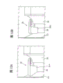
关于这一点,图1示出了在离心风扇排出口处速度分布图,其中10标识整体离心风扇,11为外壳或者风扇外壳12的锥形元件,通常称为导风板,在所述风扇外壳12内部空气在F方向上流动,13指示的是气流流过风扇外壳12的锥形元件11的区域,14所示为输出口区域,15所示为安装到输出口上用于将气流均匀化的管。In this regard, Fig. 1 shows a velocity profile at the outlet of a centrifugal fan, where 10 identifies the overall centrifugal fan, 11 is the casing or the conical element of the
图1还表示获得一个正常的速度分布图所需要的管15的长度L。Figure 1 also shows the length L of
在图1中可以清楚地看出,产生在所述管15中的气流在远离风扇10的输出口14时逐渐稳定,获得了恒定的输送状态并改进了噪声和性能。As can be clearly seen in FIG. 1 , the air flow generated in said
上文提到的有利特性也可以通过使用本发明的装置而获得,不需要在离心风扇的出口安装所述风道,而在风道的总尺寸和设计制造成本方面有好处。The advantageous properties mentioned above can also be obtained by using the device according to the invention, without the need to install said air duct at the outlet of the centrifugal fan, with advantages in terms of the overall size of the air duct and design and manufacturing costs.
本发明的另外一个特性在于它能够在使用皮带传动或任何传送发动机动力的系统情况下获得输送气流的对称化。Another characteristic of the present invention is its ability to achieve symmetrization of the delivery air flow with the use of a belt drive or any system that transmits engine power.
在图2A,2B,2C和2D中,箭头D示出了在存在传输系统16的时候,在所述锥形元件17附近,离心风扇10的输送段中的气流流向,此时这是一个共同的导风板(图2A,2B)或者是根据本发明的一个气流分离元件(图2C,2D)。In Figures 2A, 2B, 2C and 2D, arrow D shows the airflow direction in the conveying section of the
图2A,2B示出在具有共同的导风板时高和低流速情况下的结果,与使用本发明的装置(图2C,2D)获得的流动方向相比,相应地相对于在高和低流速下的操作。Figures 2A, 2B show the results at high and low flow rates with a common deflector, compared to the flow direction obtained using the device of the invention (Figures 2C, 2D), correspondingly relative to the flow at high and low operation at flow rates.
最后,本发明的另外一个优点是其大大减少了在转动过程中自然停转的趋势,这通常会在具有非常小的导风板情况下发生。Finally, another advantage of the invention is that it greatly reduces the tendency to naturally stall during rotation, which would normally occur with very small wind deflectors.
这些以及其它的一些优点通过如权利要求1所述的具有更高效率和更低噪声的离心风扇获得,为了简便起见这里引用权利要求1。These and other advantages are obtained by a more efficient and less noisy centrifugal fan as claimed in claim 1, which is hereby incorporated for brevity.
附图说明 Description of drawings
通过在下文中参照附图对本发明具有更高效率和更低噪声的离心风扇的一个优选的非限制性例子进行描述,本发明其它目的和优点将会变得更明了:Other objects and advantages of the present invention will become more apparent by describing a preferred non-limiting example of the centrifugal fan with higher efficiency and lower noise of the present invention below with reference to the accompanying drawings:
图1为一个示意图,示出根据现有技术,位于设置在离心风扇输出口处的一段直管中空气的正常速度分布图以及速度分布图的趋势;Fig. 1 is a schematic diagram showing, according to the prior art, the normal velocity profile and the trend of the velocity profile of air in a section of straight pipe arranged at the outlet of a centrifugal fan;
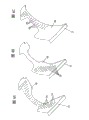
图2A-2B示意地示出没有使用本发明的稳定装置和在高和低流速情况下,在离心风扇中位于一个共同导风板附近的输送段中气流的方向,与相应的在安装了所述装置之后获得的结果相比(图2C-2D);Figures 2A-2B schematically show the direction of airflow in a delivery section near a common deflector in a centrifugal fan without using the stabilizing device of the present invention and at high and low flow rates, with corresponding installations Compared with the results obtained after the described device (FIGS. 2C-2D);
图3是离心风扇的一个透视局部剖视图,该离心风扇包括一个装置或者元件将所输送的空气气流分离,该离心风扇是根据本发明的一个例子的优选实施例制造而成,但不局限于该实施例;Figure 3 is a perspective partial cross-sectional view of a centrifugal fan including a device or element for separating the conveyed air stream, manufactured in accordance with an exemplary preferred embodiment of the present invention, but not limited thereto Example;
图4A-4C分别示出根据本发明另外一个实施例的透视图,示出了将从离心风扇输送的气流分离的装置的一部分,该部分被制作为一个整体;4A-4C are perspective views according to another embodiment of the present invention, showing a part of the device for separating the air flow delivered by the centrifugal fan, which part is made as a whole;
图5A是根据本发明的另外一个实施例的透视图,所示出的是图4A-4C中所示装置的部分;Figure 5A is a perspective view showing a portion of the device shown in Figures 4A-4C according to another embodiment of the present invention;
图5B是一个正视图,示出图5A中本发明装置的那一部分;Figure 5B is a front view showing that part of the apparatus of the present invention in Figure 5A;
图5C是一个侧视图,示出图5A中本发明装置的那一部分;Figure 5C is a side view showing that part of the apparatus of the present invention in Figure 5A;
图6是另外一个实施例的透视图,示出了图4A-4C和5A-5C中所示稳定装置的一部分,该部分被制成两个部件;Figure 6 is a perspective view of another embodiment showing a portion of the stabilizing device shown in Figures 4A-4C and 5A-5C, made in two parts;
图7A是一个实施例的透视图,示出了根据本发明的装置的一部分,可以替换图5A中的这一部分;Figure 7A is a perspective view of an embodiment showing a part of a device according to the invention, which can replace the part in Figure 5A;
图7B是一个正视图,示出图7A中本发明装置的那一部分;Figure 7B is a front view showing that part of the apparatus of the present invention in Figure 7A;
图7C是一个侧视图,示出图7A中本发明装置的那一部分;Figure 7C is a side view showing that part of the device of the present invention in Figure 7A;
图8A-8Q示出了根据本发明的一些可选择实施例,所示的是图6和7A-7C中装置的一部分的侧面轮廓;Figures 8A-8Q illustrate some alternative embodiments according to the present invention, showing the side profile of a part of the device in Figures 6 and 7A-7C;
图9A-9I示出根据本发明的导风板的各种可选择实施例,所述导风板适合于与图6和7A-7C中所示装置结合使用;Figures 9A-9I illustrate various alternative embodiments of wind deflectors suitable for use in conjunction with the devices shown in Figures 6 and 7A-7C in accordance with the present invention;
图10示出图9A-9I中的导风板之一的透视图,其中用来引导空气的部件33可以有或者没有;Figure 10 shows a perspective view of one of the wind deflectors in Figures 9A-9I, with or without the
图10A-10I示出根据本发明的图9A-9I中所示导风板的正视图的一些可选择实施例;Figures 10A-10I illustrate some alternative embodiments of the front view of the wind deflector shown in Figures 9A-9I according to the present invention;
图11A-11B示出根据本发明,图6和7A-7C中所示装置的那一部分的其它实施例的两个正视图;Figures 11A-11B show two front views of other embodiments of that part of the device shown in Figures 6 and 7A-7C, according to the present invention;
图12A-12B涉及根据本发明的离心风扇的各个部分的正视图,在其上安装着图11A-11B示出的元件,以便根据本发明粘接或没有粘接到所述出口上。Figures 12A-12B relate to front views of various parts of a centrifugal fan according to the invention, on which the elements shown in Figures 11A-11B are mounted so as to be bonded or not bonded to the outlet according to the invention.
具体实施方式Detailed ways
在对本发明的具有高效率的离心风扇的特征进行详细解释之前,应当理解本发明并不局限于在附图中所示出的详细结构情况和组件的布局,因为能够降低风扇噪声和增加效率的所述稳定装置实际上可以被制造成各种结构的实施例。Before explaining the features of the centrifugal fan with high efficiency of the present invention in detail, it should be understood that the present invention is not limited to the detailed structural conditions and the layout of components shown in the drawings, because the fan noise can be reduced and the efficiency can be increased The stabilizing device can actually be manufactured in a variety of structural embodiments.
而且,本发明可以应用到任何形状的风扇外壳和螺旋上,应用到任何类型的叶片(翼面的,平面的,倒转的,向前的,径向的叶片等),以及应用到具有单吸和双吸,任何形状的出口、前部圆盘,并且在所述出口和前部圆盘之间重叠或不相重叠的风扇。Furthermore, the invention can be applied to fan casings and spirals of any shape, to any type of blade (airfoil, planar, inverted, forward, radial, etc.), and to And double suction, outlet of any shape, front disc, and fan with or without overlap between said outlet and front disc.
详细地讲,图3示出了根据本发明的离心风扇组件,示出了实现气流稳定装置的一个例子,该稳定装置一般以20标识,所述的气流从所述离心风扇10中被释放出来。In detail, FIG. 3 shows a centrifugal fan assembly according to the present invention, showing an example of implementing airflow stabilizing means, generally indicated at 20, said airflow being released from said
在附图3中以举例说明的方式而非限制性方式,所述装置20被制作成一个整件,由于该风扇所调节和优化的情况的特殊性,该实施例按照一个特别精制和相对昂贵的方式来制造;但是,用来导引空气的叶片33可以有也可以没有,这个装置可以具有任何形状和曲率半径,因此图3中的实施例仅仅代表一个本发明保护范围内的非限制性例子。In Figure 3, by way of illustration and not by way of limitation, said device 20 is made in one piece, an embodiment according to a particularly refined and relatively expensive However, the
所述装置20被应用到所述离心风扇10上,该离心风扇10包括一个风扇外壳12,其带有平行的侧面22,23,它们被固定到风扇10涡壳24的相对边缘上。Said device 20 is applied to said
风扇外壳12具有一个大体上矩形或正方形的出风口21,一个风扇25装有一系列叶片27并以螺旋形固定在所述风扇外壳12中,该风扇可以重叠或者不重叠出口26的端部,该出口26被铆接、螺钉连接或者焊在所述侧面22上。可以使用一个传统的风扇作为风扇25,其根据输出空气气流的流动性和速度可以具有不同的形状。The
作为图3中所示结构的实施例,应用了一个稳定装置20,该装置沿着出风口21的整个宽度设置并且被制造成一整体,并且形成一个适当形状,作为图3中这个实施例的结构的替代,所述装置20还可以被分成两个或更多部分,其中图4A-4C示出一些例子(具有各种形状的轮廓28,并且如果必要的话,带有孔眼29,这些孔眼适当地位于部件28的具体部位上)。As an embodiment of the structure shown in FIG. 3, a stabilizing device 20 is applied, which is arranged along the entire width of the air outlet 21 and is manufactured in one piece, and formed into an appropriate shape, as the structure of this embodiment in FIG. 3 Alternatively, the device 20 can also be divided into two or more parts, some examples of which are shown in FIGS. 4A-4C (with
图5A-5C示出了图4A-4C的可选择实施例的各个视图;详细地讲,图5C是组成装置20的一个部分28的正交视图,其中强调了具有一个可能的曲率半径和一个具体的结构形状。5A-5C show various views of the alternative embodiment of FIGS. 4A-4C; in detail, FIG. specific structural shape.
另外,为了简化上述结构,根据本发明的装置20可以被分成两个、三个或者更多个部分30,都装设有孔眼29,如图6中举例说明;这个附图示出了组件可能的分解的一种。Furthermore, in order to simplify the structure described above, the device 20 according to the invention can be divided into two, three or
图7A-7C,8A-8Q,9A-9H和10A-10I为一些视图,它们示出了所述装置的一些例子连接到本发明的离心风扇上的情形,根据这些例子,这个装置被分裂成的各个部分在任何情形下对于实现本发明目的都是必须的。Figures 7A-7C, 8A-8Q, 9A-9H and 10A-10I are views showing some examples of the device connected to the centrifugal fan of the present invention, according to which the device is split into Each part of is in any case all necessary for realizing the object of the present invention.
这里也应该指出,各个视图之间没有预定的关系;根据一个形状制造的组件可以根据任一个其它轮廓成型,没有任何限制。It should also be noted here that there is no predetermined relationship between the various views; a component manufactured according to one shape may be formed according to any other contour without any limitation.
由这里描述的装置所获得的降低噪声的效果还可以被进一步提高,如果这种设置成一个或者多个部分的装置20被填满隔音材料(例如石棉,泡沫聚氨基甲酸酯等等),以及如果孔眼29的位置被设置和集中于装置20的不同区域,根据位于aeraulic曲线上的区域,所述aeraulic曲线需要减小噪声;以这种方式就可以获得一种创新的机理,能够将上述三个流量最佳地分离、减少、控制、稳定和利用形成在风扇外壳12内部的再循环、涡流和滞区流。The noise reduction effect obtained by the device described here can be further enhanced if the device 20 arranged in one or more parts is filled with sound-insulating material (such as rock wool, foamed polyurethane, etc.), And if the positions of the
总之,所述装置20可以安排在沿着风扇外壳12的螺旋以及出口26的圆周上的任何径向位置,并可以用完全穿孔金属片或具有一个特定比率的孔的金属片制造,所述的孔位于预先确定的区域,并且如果必要,可使用隔音材料。In general, the device 20 can be arranged at any radial position along the spiral of the
而且,根据是否在装置20的结构部分的图11A-11B中用34A示出的部分上有一个出口,所述装置20还可以被制造成完全封闭的或打开的;此时,这个装置就必须结合任何形状(三角形的,矩形,梯形的等等)的导风板使用,例如在图9A-9H和10A-10I中示例地示出。Furthermore, said device 20 can also be made completely closed or open depending on whether there is an outlet at the part shown with 34A in Figures 11A-11B of the structural part of device 20; Use with wind deflectors of any shape (triangular, rectangular, trapezoidal, etc.), such as are exemplarily shown in FIGS. 9A-9H and 10A-10I.
所述稳定装置20还可能具有任何形状和曲率半径,并可以位于与风扇外壳12和出口26邻接的部分上,并可固定或者不固定在该部分上;此时所述装置20被构造成完全或局部地重叠到风扇或叶轮25的前部圆盘。Said stabilizing means 20 may also have any shape and radius of curvature, and may be located on the portion adjoining the
所述装置20的几何布局可以容许该结构的局部装配,在这种情形,所述结构可以不具有部分28的凸出部31,32(在所述装置20被制造成一个整体的情形中)或者所述部分30的凸出部31,34(在所述装置20由至少两个部分30组成的情形中)。而且,参照图5A-5C和8A-8Q,必须指出所述部分28也可以不设置短附件(shortappendage),该短附件的位置超过了与凸出部32的交叉点。The geometric layout of the device 20 may allow partial assembly of the structure, in which case the structure may not have the
在图11A-11B和12A-12B示出的情形中,可以没有装置20的部件上的元件34A,在这些附图中,所述部件由35标识并被固定(焊接,螺钉连接,铆接等等)在邻接着风扇外壳12和出口26的部分上。In the situation shown in Figures 11A-11B and 12A-12B, there may be no
在这种情形中,所述稳定装置20可以完全地或局部地重叠在叶轮25的前部圆盘或者根本就不重叠它,并可以被焊接、螺钉连接、铆接等等到上文的支承结构上。In this case, said stabilizer 20 can completely or partially overlap the front disc of the
最后,所述装置20可以由任何材料制造,虽然在非限制性举例和优选实施例中是通常使用钢、轻合金(铝,铜等等)、塑料和/或聚酰胺。Finally, said device 20 may be manufactured from any material, although in non-limiting examples and preferred embodiments steel, light alloys (aluminum, copper, etc.), plastics and/or polyamides are commonly used.
详细地讲,在工业离心风扇上进行的实验测量已经示出通过下述装置20可以获得输出空气气流的最佳稳定并具有最小的噪声和高的效率,即,所述装置20具有四个或五个不同的部件,其中两个部件形成一个具有三角形或通用轮廓形状的导风板并固定在风扇10的出口处,而另外两个或更多部件,可以为适当形状,其被固定在与出口26邻接的一个部分上。In detail, experimental measurements carried out on industrial centrifugal fans have shown that the best stabilization of the output air flow with minimum noise and high efficiency can be obtained with a device 20 having four or Five different parts, two of which form a deflector having a triangular or general profile shape and are fixed at the outlet of the
通过上述描述,根据本发明的具有更高效率和更低噪声的离心风扇的特性以及优点已经明了。最后,很明显可以对上述具有更高效率和更小噪音的离心风扇在不脱离本发明本质主旨的前提下进行多种变化,同时在本发明的实施例中,示出的各部件的材料、形状和尺寸要可以是任何满足需要的材料,它们可以由其它技术上等同的手段替代。Through the above description, the characteristics and advantages of the centrifugal fan with higher efficiency and lower noise according to the present invention have been clarified. Finally, it is obvious that various changes can be made to the above-mentioned centrifugal fan with higher efficiency and less noise without departing from the essence of the present invention. Meanwhile, in the embodiments of the present invention, the materials, The shape and size can be any satisfactory material, and they can be replaced by other technically equivalent means.
Claims (11)
Applications Claiming Priority (2)
| Application Number | Priority Date | Filing Date | Title |
|---|---|---|---|
| IT000145A/2002 | 2002-07-02 | ||
| IT2002VI000145A ITVI20020145A1 (en) | 2002-07-02 | 2002-07-02 | ANTI-NOISE AND ANTI-VORTE DIVIDER |
Publications (2)
| Publication Number | Publication Date |
|---|---|
| CN1465868A CN1465868A (en) | 2004-01-07 |
| CN100416110C true CN100416110C (en) | 2008-09-03 |
Family
ID=29720176
Family Applications (1)
| Application Number | Title | Priority Date | Filing Date |
|---|---|---|---|
| CNB02144238XA Expired - Lifetime CN100416110C (en) | 2002-07-02 | 2002-09-29 | Anti-noise and anti-eddy current stabilizer |
Country Status (9)
| Country | Link |
|---|---|
| US (1) | US6935835B2 (en) |
| EP (1) | EP1378668B1 (en) |
| CN (1) | CN100416110C (en) |
| AT (1) | ATE321211T1 (en) |
| CA (1) | CA2400285C (en) |
| DE (1) | DE60210000T2 (en) |
| ES (1) | ES2260386T3 (en) |
| IT (1) | ITVI20020145A1 (en) |
| MX (1) | MXPA02009605A (en) |
Families Citing this family (27)
| Publication number | Priority date | Publication date | Assignee | Title |
|---|---|---|---|---|
| US7255208B2 (en) * | 2004-02-13 | 2007-08-14 | Honeywell International Inc. | Aircraft brake wheel heat shield |
| CN1877129B (en) * | 2005-06-09 | 2010-11-24 | 台达电子工业股份有限公司 | Centrifugal fan |
| US7722316B2 (en) * | 2005-09-13 | 2010-05-25 | Rolls-Royce Power Engineering Plc | Acoustic viscous damper for centrifugal gas compressor |
| US7802615B2 (en) * | 2006-02-16 | 2010-09-28 | Trane International Inc. | Sound attenuating shield for an electric heater |
| US8602156B2 (en) * | 2006-05-19 | 2013-12-10 | United Technologies Corporation | Multi-splice acoustic liner |
| EP2063130A1 (en) * | 2007-11-20 | 2009-05-27 | Siemens Aktiengesellschaft | Noise attenuation device for a centrifugal compressor discharge or suction nozzle |
| EP2182220A1 (en) * | 2008-10-28 | 2010-05-05 | Nederlandse Organisatie voor toegepast-natuurwetenschappelijk Onderzoek TNO | Turbo machine and method to reduce vibration in turbo machines. |
| ES2356873B1 (en) * | 2009-07-29 | 2012-03-15 | Soler & Palau Research S.L. | FAN HELICOCENTR�? SOUND SOUND. |
| ITFI20110177A1 (en) | 2011-08-11 | 2013-02-12 | Enel Ingegneria E Innovazione S P A | CENTRIFUGAL FAN WITH SEVENTY ANTI-ANTI-BLOOD FOR REDUCING VIBRATIONS AND NOISE |
| ITFI20110178A1 (en) | 2011-08-11 | 2013-02-12 | Enel Ingegneria E Innovazione S P A | CENTRIFUGAL FAN WITH REDUCED VIBRATIONS AND NOISE |
| TWI517782B (en) * | 2011-11-11 | 2016-01-11 | 華碩電腦股份有限公司 | Heat dissipating module |
| US8678131B2 (en) | 2012-03-30 | 2014-03-25 | Textron Innovations Inc. | Acoustic baffle for centrifugal blowers |
| JP6073604B2 (en) * | 2012-09-03 | 2017-02-01 | サンデンホールディングス株式会社 | Centrifugal blower |
| US9689264B2 (en) | 2013-03-15 | 2017-06-27 | Regal Beloit America, Inc. | Centrifugal fan impeller with variable shape fan blades and method of assembly |
| FR3054200B1 (en) * | 2016-07-19 | 2021-08-13 | Safran Landing Systems | PERFORATED AIRCRAFT BRAKE WHEEL THERMAL SCREEN |
| CN109642585A (en) * | 2016-09-02 | 2019-04-16 | 惠普发展公司, 有限责任合伙企业 | Blower-casting for noise reduction |
| JP6731325B2 (en) * | 2016-10-12 | 2020-07-29 | 日立グローバルライフソリューションズ株式会社 | Power converter and system using the same |
| GB2563614B (en) * | 2017-06-20 | 2020-06-17 | Dyson Technology Ltd | Brushless motor |
| US10415601B2 (en) * | 2017-07-07 | 2019-09-17 | Denso International America, Inc. | Blower noise suppressor |
| KR102003992B1 (en) | 2017-09-19 | 2019-07-25 | 주식회사 우현기술 | blower module maximizing air flow stabilization and efficiency |
| US11193499B2 (en) | 2017-12-15 | 2021-12-07 | Regal Beloit America, Inc. | Centrifugal blower assembly and method for assembling the same |
| CN108240357B (en) * | 2017-12-27 | 2024-05-14 | 宁波方太厨具有限公司 | Noise-reducing volute tongue of fan |
| CN110439860B (en) * | 2018-05-04 | 2025-04-15 | 宁波方太厨具有限公司 | A volute structure of a centrifugal fan |
| CN111002787B (en) * | 2018-10-08 | 2023-04-11 | 翰昂汽车零部件有限公司 | Member with through hole and vehicle air conditioner provided with same |
| CN113074137B (en) * | 2020-01-06 | 2023-06-09 | 广东威灵电机制造有限公司 | Air supply device and dust collector |
| CN118008888B (en) * | 2024-01-26 | 2026-04-10 | 中国航发湖南动力机械研究所 | Vane diffuser, vane diffuser design method and centrifugal compressor |
| CN120720283B (en) * | 2025-08-19 | 2026-01-06 | 广东海吉机电设备有限公司 | A quiet and energy-saving fan |
Citations (6)
| Publication number | Priority date | Publication date | Assignee | Title |
|---|---|---|---|---|
| US3191851A (en) * | 1963-12-31 | 1965-06-29 | Westinghouse Electric Corp | Centrifugal fans |
| EP0342484A2 (en) * | 1988-05-16 | 1989-11-23 | RIELLO CONDIZIONATORI S.p.A. | Very noiseless motor driven centrifugal fan |
| CN1019523B (en) * | 1990-03-07 | 1992-12-16 | 魏建中 | Low-noise centrifugal fan |
| US5772399A (en) * | 1993-12-21 | 1998-06-30 | American Standard Inc. | Apparatus and method for efficiency and output capacity matching in a centrifugal fan |
| EP0928899A2 (en) * | 1998-01-12 | 1999-07-14 | Mitsubishi Denki Kabushiki Kaisha | Once-through blower |
| CN1071424C (en) * | 1993-08-02 | 2001-09-19 | 福斯特·惠勒能源公司 | Rotary throat cutoff device and method for reducing centrifugal fan noise |
Family Cites Families (5)
| Publication number | Priority date | Publication date | Assignee | Title |
|---|---|---|---|---|
| US2015210A (en) * | 1934-10-13 | 1935-09-24 | Young Radiator Co | Centrifugal fan |
| US2171341A (en) * | 1936-06-01 | 1939-08-29 | Gen Electric | Fan casing |
| GB479823A (en) | 1936-06-01 | 1938-02-11 | British Thomson Houston Co Ltd | Improvements in and relating to centrifugal fans |
| US2155631A (en) | 1936-06-20 | 1939-04-25 | American Blower Corp | Blower |
| US2335734A (en) * | 1942-03-10 | 1943-11-30 | William J Caldwell | Centrifugal fan |
-
2002
- 2002-07-02 IT IT2002VI000145A patent/ITVI20020145A1/en unknown
- 2002-09-17 EP EP02078838A patent/EP1378668B1/en not_active Expired - Lifetime
- 2002-09-17 US US10/245,094 patent/US6935835B2/en not_active Expired - Lifetime
- 2002-09-17 ES ES02078838T patent/ES2260386T3/en not_active Expired - Lifetime
- 2002-09-17 AT AT02078838T patent/ATE321211T1/en not_active IP Right Cessation
- 2002-09-17 DE DE60210000T patent/DE60210000T2/en not_active Expired - Lifetime
- 2002-09-19 CA CA2400285A patent/CA2400285C/en not_active Expired - Lifetime
- 2002-09-29 CN CNB02144238XA patent/CN100416110C/en not_active Expired - Lifetime
- 2002-09-30 MX MXPA02009605A patent/MXPA02009605A/en active IP Right Grant
Patent Citations (7)
| Publication number | Priority date | Publication date | Assignee | Title |
|---|---|---|---|---|
| US3191851A (en) * | 1963-12-31 | 1965-06-29 | Westinghouse Electric Corp | Centrifugal fans |
| EP0342484A2 (en) * | 1988-05-16 | 1989-11-23 | RIELLO CONDIZIONATORI S.p.A. | Very noiseless motor driven centrifugal fan |
| EP0342484A3 (en) * | 1988-05-16 | 1990-10-03 | RIELLO CONDIZIONATORI S.p.A. | Very noiseless motor driven centrifugal fan |
| CN1019523B (en) * | 1990-03-07 | 1992-12-16 | 魏建中 | Low-noise centrifugal fan |
| CN1071424C (en) * | 1993-08-02 | 2001-09-19 | 福斯特·惠勒能源公司 | Rotary throat cutoff device and method for reducing centrifugal fan noise |
| US5772399A (en) * | 1993-12-21 | 1998-06-30 | American Standard Inc. | Apparatus and method for efficiency and output capacity matching in a centrifugal fan |
| EP0928899A2 (en) * | 1998-01-12 | 1999-07-14 | Mitsubishi Denki Kabushiki Kaisha | Once-through blower |
Also Published As
| Publication number | Publication date |
|---|---|
| ATE321211T1 (en) | 2006-04-15 |
| ITVI20020145A1 (en) | 2004-01-02 |
| US6935835B2 (en) | 2005-08-30 |
| ES2260386T3 (en) | 2006-11-01 |
| CA2400285C (en) | 2010-11-16 |
| CA2400285A1 (en) | 2004-01-02 |
| EP1378668A1 (en) | 2004-01-07 |
| CN1465868A (en) | 2004-01-07 |
| EP1378668B1 (en) | 2006-03-22 |
| MXPA02009605A (en) | 2004-07-30 |
| HK1060385A1 (en) | 2004-07-16 |
| DE60210000T2 (en) | 2006-12-07 |
| US20040005215A1 (en) | 2004-01-08 |
| DE60210000D1 (en) | 2006-05-11 |
Similar Documents
| Publication | Publication Date | Title |
|---|---|---|
| CA2400285C (en) | Anti-noise and anti-vortex flow sharing device | |
| US20240175443A1 (en) | Blower for breathing apparatus | |
| JP6143596B2 (en) | Centrifugal blower and vehicle air conditioner equipped with the centrifugal blower | |
| CN101755129B (en) | centrifugal blower | |
| CN1985093A (en) | Housing for a centrifugal fan, pump or turbine | |
| JP2000199499A (en) | Mobile blower | |
| CN110546389A (en) | Fan Improvements | |
| JPH05321891A (en) | Multiblade fan | |
| US7758305B2 (en) | Centrifugal fan with turbulence inducing inlet bell | |
| GB2562263A (en) | Bellmouth for jetfan | |
| JP2009287427A (en) | Centrifugal blower | |
| KR20100104870A (en) | Airfoil fan and air handling unit with it | |
| JP6528112B2 (en) | Centrifugal blower | |
| US10006469B2 (en) | Diffuser and method of operating diffuser | |
| RU2135837C1 (en) | Centrifugal fan | |
| JP6265843B2 (en) | Ventilation blower | |
| WO1999036701A1 (en) | Centrifugal turbomachinery | |
| JP2004308442A (en) | Centrifugal fan | |
| HK1060385B (en) | Anti-noise and anti-vortex stabilizer | |
| JPH06299994A (en) | Multiblade fan | |
| JP2023554341A (en) | Fans and fan scroll housings | |
| RU2215195C1 (en) | Centrifugal fan | |
| JP2005030349A (en) | Multi-wing fan | |
| JP2874600B2 (en) | Centripetal blower | |
| CN219220837U (en) | Volute, fan and air conditioner |
Legal Events
| Date | Code | Title | Description |
|---|---|---|---|
| C06 | Publication | ||
| PB01 | Publication | ||
| REG | Reference to a national code |
Ref country code: HK Ref legal event code: DE Ref document number: 1060385 Country of ref document: HK |
|
| C10 | Entry into substantive examination | ||
| SE01 | Entry into force of request for substantive examination | ||
| C14 | Grant of patent or utility model | ||
| GR01 | Patent grant | ||
| REG | Reference to a national code |
Ref country code: HK Ref legal event code: GR Ref document number: 1060385 Country of ref document: HK |
|
| CX01 | Expiry of patent term | ||
| CX01 | Expiry of patent term |
Granted publication date: 20080903 |