CN100416331C - camera lens - Google Patents
camera lens Download PDFInfo
- Publication number
- CN100416331C CN100416331C CNB2005101296282A CN200510129628A CN100416331C CN 100416331 C CN100416331 C CN 100416331C CN B2005101296282 A CNB2005101296282 A CN B2005101296282A CN 200510129628 A CN200510129628 A CN 200510129628A CN 100416331 C CN100416331 C CN 100416331C
- Authority
- CN
- China
- Prior art keywords
- lens
- imaging
- aberration
- image
- object side
- Prior art date
- Legal status (The legal status is an assumption and is not a legal conclusion. Google has not performed a legal analysis and makes no representation as to the accuracy of the status listed.)
- Expired - Fee Related
Links
Images




Classifications
-
- G—PHYSICS
- G02—OPTICS
- G02B—OPTICAL ELEMENTS, SYSTEMS OR APPARATUS
- G02B13/00—Optical objectives specially designed for the purposes specified below
- G02B13/18—Optical objectives specially designed for the purposes specified below with lenses having one or more non-spherical faces, e.g. for reducing geometrical aberration
-
- G—PHYSICS
- G02—OPTICS
- G02B—OPTICAL ELEMENTS, SYSTEMS OR APPARATUS
- G02B13/00—Optical objectives specially designed for the purposes specified below
- G02B13/001—Miniaturised objectives for electronic devices, e.g. portable telephones, webcams, PDAs, small digital cameras
- G02B13/0015—Miniaturised objectives for electronic devices, e.g. portable telephones, webcams, PDAs, small digital cameras characterised by the lens design
- G02B13/002—Miniaturised objectives for electronic devices, e.g. portable telephones, webcams, PDAs, small digital cameras characterised by the lens design having at least one aspherical surface
- G02B13/0035—Miniaturised objectives for electronic devices, e.g. portable telephones, webcams, PDAs, small digital cameras characterised by the lens design having at least one aspherical surface having three lenses
-
- G—PHYSICS
- G02—OPTICS
- G02B—OPTICAL ELEMENTS, SYSTEMS OR APPARATUS
- G02B13/00—Optical objectives specially designed for the purposes specified below
- G02B13/16—Optical objectives specially designed for the purposes specified below for use in conjunction with image converters or intensifiers, or for use with projectors, e.g. objectives for projection TV
-
- G—PHYSICS
- G02—OPTICS
- G02B—OPTICAL ELEMENTS, SYSTEMS OR APPARATUS
- G02B9/00—Optical objectives characterised both by the number of the components and their arrangements according to their sign, i.e. + or -
- G02B9/12—Optical objectives characterised both by the number of the components and their arrangements according to their sign, i.e. + or - having three components only
Landscapes
- Physics & Mathematics (AREA)
- General Physics & Mathematics (AREA)
- Optics & Photonics (AREA)
- Lenses (AREA)
Abstract
本发明提供了各种像差被良好地校正,光学长短,而且能确保有充分的后焦距的摄像镜头。该摄像镜头包括孔径光阑S1、第一透镜L1、第二透镜L2和第三透镜L3。按照从物体侧到像侧的顺序,由孔径光阑、第一透镜L1、第二透镜L2和第三透镜L3依次构成。第一透镜L1是物体侧及像侧的两侧面呈凸面,且具有正的屈光力的透镜,第二透镜L2是凸面朝向像侧,且具有负的屈光力的弯月形透镜,第三透镜L3是凸面朝向物体侧,且具有负的屈光力的弯月形透镜。而且,第一透镜L1、第二透镜L2和第三透镜L3三个透镜的两侧面均为非球面。
The present invention provides an imaging lens in which various aberrations are well corrected, the optical length is short, and a sufficient back focus can be ensured. The imaging lens includes an aperture stop S1, a first lens L1, a second lens L2, and a third lens L3. In order from the object side to the image side, it is composed of an aperture stop, a first lens L1, a second lens L2, and a third lens L3 in this order. The first lens L1 is a lens with convex surfaces on both sides of the object side and the image side and has positive refractive power. The second lens L2 is a meniscus lens with a convex surface facing the image side and has negative refractive power. The third lens L3 is A meniscus lens with a negative refractive power and a convex surface facing the object side. Moreover, both sides of the first lens L1 , the second lens L2 and the third lens L3 are aspherical.
Description
技术领域 technical field
本发明涉及的摄像镜头尤其适合安装于以CCD(ChargeCoupled Devices)或CMOS(Complementary Metal OxideSemiconductor)为摄像元件的手机与个人电脑的画像输入装置、数码相机、监视用CCD摄像机以及检查装置等。The imaging lens of the present invention is especially suitable for being installed in image input devices of mobile phones and personal computers, digital cameras, monitoring CCD cameras and inspection devices, etc., which use CCD (Charge Coupled Devices) or CMOS (Complementary Metal Oxide Semiconductor) as imaging elements.
背景技术 Background technique
在上述的摄像镜头中,以摄像镜头的物体侧的入射面到摄像面(CCD等的摄像面)的距离定义的光学长必须短。即在设计透镜时,光学长对摄像镜头的组合焦距的比必须小。以下,光学长短且光学长对焦距的比也小的摄像镜头,也称为小型镜头。In the imaging lens described above, the optical length defined by the distance from the incident surface on the object side of the imaging lens to the imaging surface (imaging surface such as a CCD) needs to be short. That is, when designing a lens, the ratio of the optical length to the combined focal length of the camera lens must be small. Hereinafter, an imaging lens with short optical length and a small ratio of optical length to focal length is also referred to as a compact lens.
以手机为例,摄像镜头的光学长至少要比手机本身的厚度短。另一方面,以从摄像镜头像侧的出射面到摄像面的距离定义的后焦距应尽可能长。即在设计透镜时,后焦距对焦距的比应尽可能取大。这是因为在摄像镜头和摄像面之间必须插入滤波器或保护玻璃等配件。Taking a mobile phone as an example, the optical length of the camera lens should be at least shorter than the thickness of the mobile phone itself. On the other hand, the back focus defined by the distance from the exit surface on the image side of the camera lens to the imaging surface should be as long as possible. That is, when designing the lens, the ratio of the back focal length to the focal length should be as large as possible. This is because accessories such as filters or protective glass must be inserted between the camera lens and the camera surface.
除此以外,作为摄像镜头,各种像差及画像的畸变必须被校正到充分小的程度,以致于不被肉眼所感知,且足以满足摄像元件:imaging elements(或称「像素」)的集成密度的要求。换而言之,各种像差需要被良好地校正,以下,也称各种像差被良好地校正了的画像为「良好的画像」。In addition, as a camera lens, various aberrations and image distortion must be corrected to a sufficiently small level so that it cannot be perceived by the naked eye, and it is sufficient to meet the integration of imaging elements (or "pixels") Density requirements. In other words, various aberrations need to be well corrected. Hereinafter, an image in which various aberrations are well corrected is also referred to as a "good image".
如下所示,适用于采用了CCD,CMOS等固体摄像元件的,以携带型电脑和电视电话装置等为代表的摄像装置中,具有三层结构的摄像镜头已有报道。这些镜头都既能确保广视角,又能实现小型化轻量化。As shown below, imaging lenses having a three-layer structure have been reported to be suitable for imaging devices such as portable computers and TV telephones using solid-state imaging elements such as CCD and CMOS. These lenses ensure a wide viewing angle while achieving miniaturization and weight reduction.
其中,第一类具有三层结构的摄像镜头已经公开,该摄像镜头能确保广视角,且能得到良好的画像。(例如,参照专利文献1)Among them, the first type of camera lens having a three-layer structure has been disclosed, and the camera lens can ensure a wide viewing angle and obtain a good image. (For example, refer to Patent Document 1)
但是,该摄像镜头按照从物体侧开始,由第一、第二和第三透镜的三枚透镜顺序排列构成。第一透镜L1是凸面朝向像侧且具有正的屈光力的弯月形透镜,第二透镜L2是以凸面朝向物体侧且具有负的屈光力的弯月形透镜,第三透镜L3是具有正的屈光力的凸透镜,结果造成其光学长对后焦距的比过大的结构,无法实现镜头的小型化。However, this imaging lens is composed of three lenses, first, second, and third lenses, arranged in order from the object side. The first lens L1 is a meniscus lens with a convex surface facing the image side and has positive refractive power, the second lens L2 is a meniscus lens with a convex surface facing the object side and has negative refractive power, and the third lens L3 is a meniscus lens with positive refractive power. As a result, the ratio of the optical length to the back focal length is too large, and the miniaturization of the lens cannot be achieved.
另外,第二类至第四类具有三层结构的摄像镜头分别已经公开,这些摄像镜头均能确保广视角,各种像差被良好地校正,且实现了短焦距化。(例如,参照专利文献2、专利文献3及专利文献4)In addition, second to fourth types of imaging lenses each having a three-layer structure have been disclosed. These imaging lenses can ensure a wide viewing angle, various aberrations are well corrected, and a short focal length can be realized. (For example, refer to
这些摄像镜头也如上述公开的摄像镜头一样,按照从物体侧开始,由具有不同屈光力的第一、第二和第三透镜的三枚透镜顺序排列构成。第一透镜具有正的屈光力,第二透镜具有负的屈光力,第三透镜具有正的屈光力。该摄像镜头的组合焦距虽然能设计得短,然而后焦距和光学长都过长。而且由于利用了玻璃材料透镜,所以成本高。These imaging lenses are also the same as the above-mentioned disclosed imaging lenses, and are composed of three lenses arranged in order from the object side, namely first, second and third lenses with different refractive powers. The first lens has positive refractive power, the second lens has negative refractive power, and the third lens has positive refractive power. Although the combined focal length of this camera lens can be designed to be short, the back focus and the optical length are too long. And because the lens made of glass material is used, the cost is high.
已经公开的第五类具有三层结构的摄像镜头中,通过采用非球面透镜和设计功率分配及透镜表面形状而实现摄像镜头的小型化。(例如,参照专利文献5)In the fifth disclosed camera lens with a three-layer structure, the miniaturization of the camera lens is realized by adopting an aspheric lens and designing power distribution and lens surface shape. (For example, refer to Patent Document 5)
但是,该摄像镜头按照从物体侧开始,由具有不同的屈光力的第一、第二和第三透镜的三枚透镜顺序排列构成。第一透镜具有负的屈光力,第二透镜具有正的屈光力,第三透镜具有负的屈光力,结果成为相对合成焦距而言,光学长的摄像镜头。且因为利用了玻璃材料,所以成本高。However, this imaging lens is composed of three lenses, first, second and third lenses having different refractive powers, arranged in order from the object side. The first lens has a negative refractive power, the second lens has a positive refractive power, and the third lens has a negative refractive power, resulting in an imaging lens that is optically long relative to the combined focal length. And because the glass material is used, the cost is high.
已经公开的第六类具有三层结构的摄像镜头中,含有一组各自至少有一个非球面表面而且互相以凹面朝向对方的弯月形的塑性材料透镜,整个透镜系统由三枚透镜组成。此摄像镜头在实现小型化和降低成本的同时,能够简单地抑制由于温度变化而引起的焦点移动。(例如,参照专利文献6)The sixth type of disclosed camera lens with a three-layer structure contains a group of meniscus-shaped plastic material lenses each having at least one aspheric surface and facing each other with concave surfaces. The entire lens system is composed of three lenses. This imaging lens can easily suppress focus shift due to temperature changes while achieving miniaturization and cost reduction. (For example, refer to Patent Document 6)
但是,此摄像镜头按照从物体侧开始,由具有不同的屈光力的第一、第二和第三透镜的三枚透镜顺序排列构成。第一透镜具有弱屈光力,第二透镜也具有弱屈光力,第三透镜具有正的屈光力。因此仅仅依靠第三透镜不能补偿第一透镜和第二透镜的屈光力,结果导致与合成焦距相比,后焦距变长且光学长也变长。而且,因为第三透镜为玻璃透镜,所以不能完全降低成本。However, this imaging lens is composed of three lenses, first, second and third lenses having different refractive powers, arranged in order from the object side. The first lens has weak refractive power, the second lens also has weak refractive power, and the third lens has positive refractive power. Therefore, only relying on the third lens cannot compensate the refractive power of the first lens and the second lens, and as a result, the back focal length becomes longer and the optical length becomes longer than the combined focal length. Also, since the third lens is a glass lens, the cost cannot be completely reduced.
已经公开的第七类具有三层结构的摄像镜头中,整个透镜系分为前、后两组。该摄像镜头为,前组具有正的屈光力,后组具有负的屈光力的望遠型结构。摄像镜头的光学长短且价格廉宜。(例如,参照专利文献7)In the seventh disclosed camera lens with a three-layer structure, the entire lens system is divided into two groups, front and rear. The imaging lens has a telephoto structure in which the front group has positive refractive power and the rear group has negative refractive power. Camera lenses are optically short and inexpensive. (For example, refer to Patent Document 7)
但是,此透镜组按照从物体侧开始,由具有不同的屈光力的第一、第二和第三透镜的三枚透镜顺序排列构成。第一透镜具有负的屈光力,第二透镜具有正的屈光力,第三透镜具有负的屈光力,而且第二透镜与第三透镜的间距大。因此,与合成焦距相比光学长过长,及第三透镜孔径过大的问题,不适合装载于手机与个人电脑的画像输入装置、数码相机、监视用CCD摄像机以及检查装置等。However, this lens group is composed of three lenses, first, second and third lenses having different refractive powers, arranged sequentially from the object side. The first lens has negative refractive power, the second lens has positive refractive power, and the third lens has negative refractive power, and the distance between the second lens and the third lens is large. Therefore, the optical length is too long compared with the composite focal length, and the aperture of the third lens is too large, so it is not suitable for image input devices for mobile phones and personal computers, digital cameras, CCD cameras for monitoring, and inspection devices.
已经公开的第八类具有三层结构的摄像镜头中,从物体侧开始由两枚正透镜和一枚两面均为非球面且以凹面朝向像侧的负透镜组成。从透镜中心至透镜周边,该负透镜的负功率逐渐变弱,而在周边部透镜的功率转变为正。(例如,参照专利文献8)In the eighth type of disclosed imaging lens with a three-layer structure, it consists of two positive lenses from the object side and a negative lens with both aspherical surfaces and a concave surface facing the image side. From the center of the lens to the periphery of the lens, the negative power of the negative lens gradually becomes weaker, and the power of the lens changes to positive at the periphery. (For example, refer to Patent Document 8)
但是,此透镜组的特点是相当于第三透镜L3的透镜从透镜中心至透镜周边负功率逐渐变弱,透镜的功率转变为正的位置距透镜中心距离在透镜的有效孔径的0.7倍~1.0倍范围内。被公开的摄像镜头的实施例中,镜头的功率由负值转变为正值的转折点到透镜中心的距离分别为透镜有效孔径的0.96倍和0.97倍,几乎位于透镜的周边部。However, the feature of this lens group is that the negative power of the lens equivalent to the third lens L3 gradually weakens from the center of the lens to the periphery of the lens, and the distance between the position where the power of the lens turns positive and the center of the lens is 0.7 times to 1.0 times the effective aperture of the lens times range. In the disclosed embodiment of the imaging lens, the distances from the turning point of the lens power from negative value to positive value to the center of the lens are respectively 0.96 times and 0.97 times the effective aperture of the lens, almost located at the periphery of the lens.
如果把镜头的功率转变为正的转折点设于透镜的周边部,入射到透镜光轴与摄像面交点附近以及入射到透镜周边部的光,对摄像元件的入射角接近直角,然而入射到透镜光轴与摄像面交点到透镜周边部之间的光,对摄像元件的入射角就远离直角。也就是说,到透镜周边部之间的占画像重要部份的光,对摄像元件的入射角远离直角,因为光从倾斜方向入射到摄像元件而在入射面的反射量增加,所以输送到摄像元件的光电转换面的光能量变小,因此产生这部份画像变暗的问题。If the turning point where the power of the lens is converted to positive is set at the periphery of the lens, the light incident on the vicinity of the intersection of the optical axis of the lens and the imaging surface and the periphery of the lens will have an incident angle close to a right angle to the imaging element, but the light incident on the lens will The incident angle of the light between the intersection point of the axis and the imaging surface and the peripheral portion of the lens is far from a right angle to the imaging element. That is to say, the light that accounts for an important part of the image between the peripheral parts of the lens has an incident angle to the imaging element that is far away from a right angle. The light energy of the photoelectric conversion surface of the element is reduced, so there is a problem of darkening the image in this part.
已经公开的第九类具有三层结构的摄像镜头中,从物体侧开始由孔径光阑,两面为凸状的正透镜的第一透镜,以凹面朝向物体侧的负透镜的第二透镜,和凸面朝向物体侧的弯月形透镜组成。(例如,参照专利文献9)In the ninth type of disclosed imaging lens having a three-layer structure, starting from the object side, there is an aperture stop, a first lens having a convex positive lens on both sides, a second lens having a negative lens with a concave surface facing the object side, and A meniscus lens with a convex surface facing the object side. (For example, refer to Patent Document 9)
此透镜组的设计,使得在第一透镜的物体侧设置了孔径光阑的情况下,可以得到良好的画象。通过在第一透镜的物体侧设置孔径光阑,可以使得入射光瞳的位置接近于物体。因而主光线以接近于垂直角度入射到画像面的特点。如果主光线以倾斜角度入射到画像面,就会产生入射到设置于画像面的画素(摄像元件)的入射光量减少的Shading现象,因此画面的周边部份画像会变暗。The design of this lens group makes it possible to obtain a good image under the condition that an aperture stop is arranged on the object side of the first lens. By providing an aperture stop on the object side of the first lens, the position of the entrance pupil can be made close to the object. Therefore, the chief ray is incident on the image surface at a near-vertical angle. If the chief ray enters the image surface at an oblique angle, a shading phenomenon occurs in which the amount of incident light incident on the pixels (imaging elements) installed on the image surface decreases, so the image around the image becomes dark.
该问题是由于,当光线从摄像元件的倾斜方向入射到摄像元件时,在摄像元件表面产生的反射量会增加,传送到摄像元件的光电转换面的光量减少而产生的。因此,通过在第一透镜的物体侧设置孔径光阑,可以设计不易产生Shading现象的摄像镜头。This problem is caused by the fact that when light enters the imaging element from an oblique direction, the amount of reflection on the surface of the imaging element increases and the amount of light transmitted to the photoelectric conversion surface of the imaging element decreases. Therefore, by providing an aperture stop on the object side of the first lens, it is possible to design an imaging lens that is less prone to shading.
对根据以上的设计方针而设计的摄像镜头,更进一步以防止画像的对比度减少现象的耀光(即Flare)或画像浸润现象(即Smear)为目的,在第一透镜与第二透镜之间加设孔径光阑后,将产生以下问题。即,在透过孔径光阑的主光线中,对摄像镜头的光轴具有大入射角的主光线,会被孔径光阑遮断。因而,该孔径光阑在遮断造成耀光或浸润等引起画质下降的原因的迷光的同时,会遮断如上所述的一部分主光线,有时甚至会产生画像的周边部份的光量减少,画像的周边部份变暗的问题。For the camera lens designed according to the above design guidelines, further for the purpose of preventing the contrast reduction phenomenon of the image (that is, Flare) or the image infiltration phenomenon (that is, Smear), an additional lens is added between the first lens and the second lens. After setting the aperture stop, the following problems will arise. That is, among the chief rays passing through the aperture stop, the chief rays having a large incident angle to the optical axis of the imaging lens are blocked by the aperture stop. Therefore, the aperture stop cuts off the stray light that causes the image quality degradation, such as flare or immersion, and at the same time cuts off a part of the above-mentioned chief light rays, and sometimes even reduces the amount of light in the peripheral part of the image, resulting in a blurred image. The problem that the surrounding part becomes dark.
另外,该摄像镜头具有,相当于第三透镜为具有正的屈光力的弯月形透镜的特征,因此相对于光学长来说,后焦距相对短。即,如在摄像透镜与透镜面之间插入滤波器或保护玻璃等配件,将使后焦距变长则光学长也相应变长,结果造成摄像镜头本身过大的问题。In addition, this imaging lens is characterized in that the third lens element is a meniscus lens having positive refractive power, and therefore the back focal length is relatively short relative to the optical length. That is, inserting accessories such as a filter or a cover glass between the imaging lens and the lens surface will increase the back focal length and increase the optical length accordingly, resulting in the problem that the imaging lens itself is too large.
第十类具有三层结构的摄像镜头中,从物体侧开始,由以凸面朝向物体侧的正透镜的第一透镜,光阑,由塑料材料构成的至少有一个非球面的,以凹面朝向物体侧的具有正或负的屈光力的第二透镜,和有两个非球面且以凸面朝向物体侧的具有正的屈光力的第三透镜组成。(例如,参照专利文献10)In the tenth category of camera lenses with a three-layer structure, starting from the object side, the first lens of the positive lens with the convex surface facing the object side, the diaphragm, made of plastic materials with at least one aspheric surface, and the concave surface facing the object The second lens with positive or negative refractive power on the side, and the third lens with positive refractive power with two aspherical surfaces and the convex surface facing the object side. (For example, refer to Patent Document 10)
第十类具有三层结构的摄像镜头,在第一透镜与第二透镜之间设置光阑,以该光阑具有孔径光阑的功能为前提,设计成可以取得良好的画像。即,如把快门等设于第一透镜的物体侧,由于快门等的原因镜头的入射口径变窄。因此,该快门等实质上具有光阑的作用,使得入射到光阑上的主光线的一部分被遮断。对镜头的光轴具有大入射角的主光线,即形成画像的周边部的光线,被设置在第一透镜的物体侧的快门等遮断,就可能产生画像的周边部份变暗的问题。The tenth category is a camera lens with a three-layer structure. A diaphragm is provided between the first lens and the second lens. The diaphragm is designed to obtain a good image on the premise that the diaphragm has the function of an aperture diaphragm. That is, if a shutter or the like is provided on the object side of the first lens, the incident aperture of the lens becomes narrow due to the shutter or the like. Therefore, the shutter or the like substantially functions as a stop, and a part of the chief ray incident on the stop is blocked. The chief ray with a large incident angle to the optical axis of the lens, that is, the light forming the peripheral portion of the image, is blocked by the shutter or the like provided on the object side of the first lens, which may cause the peripheral portion of the image to become dark.
另外,该摄像镜头与第九类三层结构的摄像镜头相同,相当于第三透镜的透镜为具有正的屈光力的弯月形透镜。因而,该摄像镜头与第九类三层结构的摄像镜头相同,后焦距变长则光学长也相应变长,结果同样产生摄像镜本身过大的问题。In addition, this imaging lens is the same as the ninth type of imaging lens with a three-layer structure, and the lens corresponding to the third lens is a meniscus lens with positive refractive power. Therefore, this camera lens is the same as the camera lens with the ninth type of three-layer structure, and the optical length becomes longer as the back focal length becomes longer, resulting in the same problem that the camera lens itself is too large.
第十一类具有三层结构的摄像镜头中,从物体侧开始,由以玻璃材料构成的凸面朝向物体侧的具有正的屈光力的第一透镜,光阑,由塑料材料构成的至少有一个非球面的凹面朝向物体侧的具有正的屈光力弯月形的第二透镜,和以塑料材料构成的有两个非球面且凸面朝向物体侧的具有正或负的屈光力的第三透镜组成。(例如,参照专利文献11)In the eleventh type of camera lens with a three-layer structure, starting from the object side, the first lens with positive refractive power, the diaphragm made of plastic material, and at least one non- The concave surface of the spherical surface faces the object side and has a positive refractive power meniscus second lens, and the third lens made of plastic material has two aspherical surfaces and the convex surface faces the object side and has positive or negative refractive power. (For example, refer to Patent Document 11)
第十一类三层结构的摄像镜头与第十类三层结构的摄像镜头的基本构成相同,所以与第十类三层结构的摄像镜头有相同的问题。The eleventh category of three-layer structure camera lens has the same basic composition as the tenth category of three-layer structure camera lens, so it has the same problems as the tenth category of three-layer structure camera lens.
第十二类具有三层结构的摄像镜头中,从物体侧开始,由至少有一个非球面和两个凸面的具有正的屈光力的第一透镜,光阑,至少有一个非球面的凸面朝向物体侧的具有正的屈光力弯月形透镜的第二透镜,和以塑料材料构成的有两个非球面且凸面朝向物体侧的具有正或负的屈光力的第三透镜组成。(例如,参照专利文献12)In the twelfth category of camera lenses with a three-layer structure, starting from the object side, the first lens with positive refractive power having at least one aspheric surface and two convex surfaces, the diaphragm, and the convex surface of at least one aspherical surface facing the object The second lens is a meniscus lens with positive refractive power on the side, and the third lens with positive or negative refractive power is made of plastic material and has two aspherical surfaces and the convex surface faces the object side. (For example, refer to Patent Document 12)
第十二类三层结构的摄像镜头与第十类及第十一类三层结构的摄像镜头的基本构成相同,所以与第十类及第十一类三层结构的摄像镜头有同样的问题。The basic composition of the twelfth category three-layer structure camera lens is the same as that of the tenth and eleventh category three-layer structure camera lens, so it has the same problem as the tenth and eleventh category three-layer structure camera lens .
第十三类具有三层结构的摄像镜头中,从物体侧开始,由凸面朝向物体侧的具有正的屈光力的第一透镜,凸面朝向像侧的具有负的屈光力的弯月形的第二透镜,和凸面朝向物体侧的具有正的屈光力的第三透镜组成。并且说明,第一透镜的物体侧设置光阑的摄像镜头,和在第一透镜与第二透镜之间设置光阑的摄像镜头。(例如,参照专利文献13)In the thirteenth type of imaging lens with a three-layer structure, starting from the object side, a first lens with a positive refractive power with a convex surface facing the object side, and a meniscus-shaped second lens with a negative refractive power with a convex surface facing the image side , and a third lens with a positive refractive power with a convex surface facing the object side. Also, an imaging lens in which a diaphragm is provided on the object side of the first lens and an imaging lens in which a diaphragm is provided between the first lens and the second lens will be described. (For example, refer to Patent Document 13)
即,以第一透镜的物体侧设置的光阑具有孔径光阑作用为前提,设计的可以取得良好的画像的摄像镜头,和以在第一透镜与第二透镜之间设置的光阑具有孔径光阑作用为前提,设计的可以取得良好的画像的摄像镜头。That is, on the premise that the diaphragm provided on the object side of the first lens has the function of an aperture diaphragm, the imaging lens that can obtain a good image is designed, and the diaphragm provided between the first lens and the second lens has an aperture. Based on the premise of the aperture function, the camera lens is designed to obtain a good image.
如上所述,在第一透镜的物体侧设置的光阑具有孔径光阑作用的前提下,设计的可以取得良好的画像的摄像镜头,再在第一透镜与第二透镜之间加设光阑,通过孔径光阑的主光线中,对摄像镜头的光轴具有大入射角的主光线,会被加设的光阑遮断。同样,在第一透镜与第二透镜之间设置的光阑具有孔径光阑作用的前提下,设计的可以取得良好的画像的摄像镜头,再在第一透镜的物体侧加设光阑,通过孔径光阑的主光线中,对摄像镜头的光轴具有大入射角的主光线,会被加设的光阑遮断。As mentioned above, on the premise that the diaphragm on the object side of the first lens has the function of an aperture diaphragm, a photographic lens that can obtain a good image is designed, and a diaphragm is added between the first lens and the second lens. , among the chief rays passing through the aperture diaphragm, the chief rays with a large incident angle to the optical axis of the camera lens will be blocked by the additional diaphragm. Similarly, under the premise that the diaphragm provided between the first lens and the second lens has the effect of an aperture diaphragm, the designed camera lens that can obtain a good image is then added to the object side of the first lens, through Among the chief rays of the aperture diaphragm, the chief rays having a large incident angle to the optical axis of the camera lens will be blocked by the additional diaphragm.
可知,如上所述,在遮断造成耀光或浸润等引起画质下降的原因的迷光的同时,由于如上所述的主光线的一部分被遮断,有时甚至会产生到画像的周边部份的光量减少,画像的周边部份变暗的问题。It can be seen that, as described above, while blocking the stray light that causes the image quality degradation such as flare and immersion, since a part of the above-mentioned chief ray is blocked, the amount of light reaching the peripheral part of the image sometimes decreases. , the problem that the peripheral part of the image becomes dark.
在专利文献13中,对第一透镜的物体侧设置孔径光阑的摄像镜头,和在第一透镜与第二透镜之间设置孔径光阑的摄像镜头,分别在不同的实施例设计中进行了说明。即,对应于不同的孔径光阑的设置位置,为了能得到良好的画像,分别对第一透镜至第三透镜的形状及其透镜的设置进行了设计。即,对在第一透镜的物体侧设置了光阑,并且在第一透镜与第二透镜之间也设置了孔径光阑的摄像镜头,并未进行说明。换而言之,对除确定入射光瞳位置的孔径光阑外,还同时具有为提高镜头的性能而设,以防止耀光或画像浸润等为目的的光阑的摄像镜头,未进行说明。In Patent Document 13, the imaging lens in which an aperture stop is provided on the object side of the first lens, and the imaging lens in which an aperture stop is provided between the first lens and the second lens are respectively designed in different embodiments. illustrate. That is, the shapes of the first lens to the third lens and the arrangement of the lenses are respectively designed in order to obtain a good image corresponding to different installation positions of the aperture stop. That is, the imaging lens in which a stop is provided on the object side of the first lens and an aperture stop is also provided between the first lens and the second lens will not be described. In other words, there is no description of an imaging lens that has, in addition to the aperture stop for determining the position of the entrance pupil, a stop for improving the performance of the lens and preventing flare or image blurring.
另外,第十三类三层结构的摄像镜头,与第九类三层结构的摄像镜头相同,相当于第三透镜的透镜为具有正的屈光力的弯月形透镜。因而,该摄像镜头与第九类三层结构的摄像镜头相同,后焦距变长则光学长也相应变长,结果造成摄像镜头本身过大的同样问题。In addition, the thirteenth type of imaging lens with three-layer structure is the same as the ninth type of imaging lens with three-layer structure, and the lens corresponding to the third lens is a meniscus lens with positive refractive power. Therefore, this camera lens is the same as the camera lens with the ninth type of three-layer structure, and the optical length becomes longer when the back focal length becomes longer, resulting in the same problem that the camera lens itself is too large.
第十四类具有三层结构的摄像镜头中,从物体侧开始,由凸面朝向物体侧的具有正的屈光力的第一透镜,孔径光阑,以凸面朝向像侧且具有正的屈光力的弯月形透镜的第二透镜,和凹面朝向像侧的具有负的屈光力的第三透镜组成。(例如,参照专利文献14)In the fourteenth category of imaging lens with a three-layer structure, starting from the object side, the first lens with a positive refractive power with a convex surface facing the object side, an aperture stop, and a meniscus with a positive refractive power with a convex surface facing the image side The second lens is a shaped lens, and the third lens has a negative refractive power with a concave surface facing the image side. (For example, refer to Patent Document 14)
该撮像镜头中,将第一透镜的焦距f1与撮像镜头的组合焦距f的比值f1/f,设计成满足0.8<f1/f<2.0。因此只得取弱的第一透镜屈光力和长的光学长,结果不能实现小型化。而且,因为采用具有正的屈光力的透镜作为第二透镜,不得不缩短该第二透镜的像侧面(朝向像侧的凸面)的曲率半径。因此,由于透镜面的曲率增大,使得铸型加工困难。In the imaging lens, the ratio f1/f of the focal length f1 of the first lens to the combined focal length f of the imaging lens is designed to satisfy 0.8<f1/f<2.0. Therefore, the first lens has to be weak in refractive power and long in optical length, and as a result, miniaturization cannot be achieved. Furthermore, since a lens having positive refractive power is used as the second lens, the radius of curvature of the image side (convex surface toward the image side) of the second lens has to be shortened. Therefore, molding processing is difficult due to the increased curvature of the lens surface.
【专利文献1】特开平2001-075006号公报[Patent Document 1] JP-A-2001-075006 Gazette
【专利文献2】特开平2003-149548号公报[Patent Document 2] Japanese Patent Laid-Open Publication No. 2003-149548
【专利文献3】特开平2002-221659号公报[Patent Document 3] Japanese Patent Laid-Open Publication No. 2002-221659
【专利文献4】特开平2002-244030号公报[Patent Document 4] Japanese Unexamined Patent Application Publication No. 2002-244030
【专利文献5】特开平2003-149545号公报[Patent Document 5] JP-A-2003-149545 Gazette
【专利文献6】特开平10-301022号公报[Patent Document 6] Japanese Unexamined Patent Publication No. 10-301022
【专利文献7】特开平10-301021号公报[Patent Document 7] Japanese Unexamined Patent Publication No. 10-301021
【专利文献8】特开平2003-322792号公报[Patent Document 8] Japanese Unexamined Patent Application Publication No. 2003-322792
【专利文献9】特开平2004-4566号公报[Patent Document 9] JP-A-2004-4566 Gazette
【专利文献10】特开平2004-302058号公报[Patent Document 10] Japanese Unexamined Patent Application Publication No. 2004-302058
【专利文献11】特开平2004-302059号公报[Patent Document 11] Japanese Patent Laid-Open Publication No. 2004-302059
【专利文献12】特开平2004-302060号公报[Patent Document 12] Japanese Unexamined Patent Application Publication No. 2004-302060
【专利文献13】特开平2005-4045号公报[Patent Document 13] Japanese Unexamined Patent Publication No. 2005-4045
【专利文献14】特开平2005-242286号公报[Patent Document 14] Japanese Unexamined Patent Publication No. 2005-242286
发明内容 Contents of the invention
本发明的目的是为了提供适合用于以CCD或CMOS为摄像元件的摄像机的摄像镜头,该摄像镜头的光学长短,后焦距尽量长,同时能获得良好的画像。光学长短的具体表示为光学长对焦距的比小。后焦距长的具体表示为后焦距对焦距的比大。The object of the present invention is to provide an imaging lens suitable for a camera using CCD or CMOS as an imaging element, the optical length of the imaging lens is as long as possible, and a good image can be obtained at the same time. The specific expression of the optical length is that the ratio of the optical length to the focal length is small. The specific expression of the long back focal length is that the ratio of the back focal length to the focal length is large.
另外本发明中,因构成摄像镜头的所有透镜(三枚)均利用塑性材料形成,从而实现了低成本及轻量化。这里所指的塑性材料,是指可通过加热或/和加压而产生塑性变形而形成透镜且可以透过可见光的高分子物质。In addition, in the present invention, since all the lenses (three lenses) constituting the imaging lens are formed of plastic materials, low cost and weight reduction are achieved. The plastic material referred to here refers to a polymer substance that can be plastically deformed by heating or/and pressure to form a lens and can transmit visible light.
为了实现上述目的,第一发明的摄像镜头具有,孔径光阑S1、第一透镜L1、第二透镜L2和第三透镜L3,按照从物体侧到像侧顺序,由孔径光阑S1、第一透镜L1、第二透镜L2和第三透镜L3排列构成。第一透镜L1是以凸面朝向物体侧及像侧具有正的屈光力的透镜,第二透镜L2是凸面朝向像侧且具有负的屈光力的弯月形透镜,第三透镜L3是以凸面朝向物体侧具有负的屈光力的透镜。In order to achieve the above object, the imaging lens of the first invention has the aperture stop S1, the first lens L1, the second lens L2 and the third lens L3, in order from the object side to the image side, consisting of the aperture stop S1, the first lens L1, and the second lens L3. The lens L1, the second lens L2 and the third lens L3 are arranged in an arrangement. The first lens L1 is a lens having positive refractive power with a convex surface facing the object side and the image side, the second lens L2 is a meniscus lens with a negative refractive power having a convex surface facing the image side, and the third lens L3 is a lens with a convex surface facing the object side. A lens with negative refractive power.
而且,第一透镜L1的两面、第二透镜L2的两面、而第三透镜L3的两面为非球面。Furthermore, both surfaces of the first lens L1, both surfaces of the second lens L2, and both surfaces of the third lens L3 are aspheric surfaces.
而且,根据本发明的实施例可知,此摄像镜头满足以下的条件式(1-1)至(1-4)。Moreover, according to the embodiments of the present invention, it can be seen that the imaging lens satisfies the following conditional expressions (1-1) to (1-4).
0.01<|r2/r3|<0.05 (1-1)0.01<|r2/r3|<0.05 (1-1)
0.05<D/f≤0.1 (1-2)0.05<D/f≤0.1 (1-2)
0.6<L/(2Y)<0.9 (1-3)0.6<L/(2Y)<0.9 (1-3)
0.5<f1/f<0.7 (1-4)0.5<f1/f<0.7 (1-4)
式中,In the formula,
f:摄像镜头的组合焦距f: Combined focal length of camera lens
r2:第一透镜L1物体侧的光轴附近的曲率半径(轴上曲率半径)r2: Radius of curvature near the optical axis on the object side of first lens L1 (on-axis curvature radius)
r3:第一透镜L1像侧的光轴附近的曲率半径(轴上曲率半径)r3: Radius of curvature near the optical axis on the image side of the first lens L1 (on-axis curvature radius)
D:第二透镜L2与第三透镜L3的光轴上的间距D: the distance between the second lens L2 and the third lens L3 on the optical axis
L:在空气中从第一透镜L1的物体侧到摄像面的光轴上的距离L: Distance on the optical axis from the object side of the first lens L1 to the imaging surface in air
2Y:像高(有效画面的对角线长)2Y: image height (diagonal length of the effective screen)
f1:第一透镜L1的焦距f1: focal length of the first lens L1
以从摄像镜头像侧的出射面到摄像面的距离而定义的后焦距bf,本文中指从第三透镜L3的像侧面到摄像面的距离。像高2Y指有效画面的对角线长,即,指设置于摄像镜头的摄像面上的固体摄像元件的矩形受光面的对角线长度。The back focus bf defined by the distance from the exit surface on the image side of the camera lens to the imaging surface refers to the distance from the image side of the third lens L3 to the imaging surface in this document. The image height 2Y refers to the diagonal length of the effective screen, that is, the diagonal length of the rectangular light-receiving surface of the solid-state imaging element provided on the imaging surface of the imaging lens.
第二发明的摄像镜头具有,第一透镜L1、孔径光阑S2、第二透镜L2和第三透镜L3,按照从物体侧到像侧顺序,由第一透镜L1、孔径光阑S2、第二透镜L2和第三透镜L3构成。第一透镜L1是以凸面朝向物体侧及像侧具有正的屈光力的透镜,第二透镜L2是凸面朝向像侧且具有负的屈光力的弯月形透镜,第三透镜L3是以凸面朝向物体侧具有负的屈光力的弯月形透镜。The imaging lens of the second invention has a first lens L1, an aperture stop S2, a second lens L2, and a third lens L3. In order from the object side to the image side, the first lens L1, the aperture stop S2, the second lens The lens L2 and the third lens L3 constitute. The first lens L1 is a lens having positive refractive power with a convex surface facing the object side and the image side, the second lens L2 is a meniscus lens with a negative refractive power having a convex surface facing the image side, and the third lens L3 is a lens with a convex surface facing the object side. A meniscus lens with negative refractive power.
而且,第一透镜L1的两面、第二透镜L2的两面、而第三透镜L3的两面为非球面。Furthermore, both surfaces of the first lens L1, both surfaces of the second lens L2, and both surfaces of the third lens L3 are aspheric surfaces.
而且,根据本发明的实施例可知,此摄像镜头满足以下的条件式(2-1)至(2-4)。Furthermore, according to the embodiments of the present invention, it can be seen that the imaging lens satisfies the following conditional expressions (2-1) to (2-4).
0.01<|r1/r2|<0.05 (2-1)0.01<|r1/r2|<0.05 (2-1)
0.05<D/f≤0.1 (2-2)0.05<D/f≤0.1 (2-2)
0.6<L/(2Y)<0.9 (2-3)0.6<L/(2Y)<0.9 (2-3)
0.5<f1/f<0.7 (2-4)0.5<f1/f<0.7 (2-4)
式中,In the formula,
f:摄像镜头的组合焦距f: Combined focal length of camera lens
r1:第一透镜L1物体侧的光轴附近的曲率半径(轴上曲率半径)r1: radius of curvature near the optical axis on the object side of first lens L1 (on-axis curvature radius)
r2:第一透镜L1像侧的光轴附近的曲率半径(轴上曲率半径)r2: Radius of curvature near the optical axis on the image side of the first lens L1 (on-axis curvature radius)
D:第二透镜L2与第三透镜L3的光轴上的间距D: the distance between the second lens L2 and the third lens L3 on the optical axis
L:在空气中从第一透镜L1的物体侧到摄像面的光轴上的距离L: Distance on the optical axis from the object side of the first lens L1 to the imaging surface in air
2Y:像高(有效画面的对角线长)2Y: image height (diagonal length of the effective screen)
f1:第一透镜L1的焦距f1: focal length of the first lens L1
这里,空气中的距离是指,在第三透镜L3到摄像面之间插入了如滤波器或保护玻璃等配件的平行平板时,将该平行平板部分换算成空气中的距离计算上述L值。以下相同,空气中的距离是指,将平行平板部分作为空气中的换算距离从而计算所得的距离值。即,当平行平板部分的几何距离为a,折射率为n时,该距离a将被换算为a/n。Here, the distance in air means that when a parallel plate with accessories such as a filter or cover glass is inserted between the third lens L3 and the imaging surface, the above-mentioned L value is calculated by converting the parallel plate portion into the distance in air. Hereinafter, the distance in the air refers to the distance value calculated by using the parallel plate portion as the converted distance in the air. That is, when the geometric distance of the parallel plate part is a and the refractive index is n, the distance a will be converted into a/n.
以从摄像镜头的像侧出射面到摄像面的距离而定义的后焦距bf,本文中指从第三透镜L3的像侧面到摄像面的距离。像高2Y指有效画面的对角线长,即,指设置于摄像镜头的摄像面上的固体摄像元件的,矩形受光面的对角线长度。The back focal length bf defined by the distance from the image side exit surface of the imaging lens to the imaging plane refers to the distance from the image side of the third lens L3 to the imaging plane herein. The image height 2Y refers to the diagonal length of the effective screen, that is, refers to the diagonal length of the rectangular light-receiving surface of the solid-state imaging element disposed on the imaging surface of the imaging lens.
第二发明的摄像镜头中,因在第一透镜L1和第二透镜L2之间设置孔径光阑S2,第一透镜L1到第二透镜L2的光轴上的间距D如下定义。即,间距D为第一透镜L1像侧面到孔径光阑S2的间距与孔径光阑S2到第二透镜L2物体侧面的间距之和。In the imaging lens of the second invention, since the aperture stop S2 is provided between the first lens L1 and the second lens L2, the distance D on the optical axis from the first lens L1 to the second lens L2 is defined as follows. That is, the distance D is the sum of the distance from the image side of the first lens L1 to the aperture stop S2 and the distance from the aperture stop S2 to the object side of the second lens L2 .
第一发明的摄像镜头及第二发明的摄像镜头中适合为,第二透镜L2的材料的折射率比第一透镜L1及第三透镜L3的材料的折射率大,第二透镜L2的材料的阿贝数比第一透镜L1及第三透镜L3的材料的阿贝数小。In the imaging lens of the first invention and the imaging lens of the second invention, the refractive index of the material of the second lens L2 is larger than the refractive index of the material of the first lens L1 and the third lens L3, and the material of the second lens L2 is The Abbe number is smaller than the Abbe numbers of the materials of the first lens L1 and the third lens L3.
另外,第一发明的摄像镜头及第二发明的摄像镜头中,第一透镜L1、第二透镜L2和第三透镜L3应由阿贝数为27到60范围内的材料形成。而且,第一透镜L1及第三透镜L3透镜最好由环烯塑料,而第二透镜L2最好由芴类聚酯或聚碳酸酯材料形成。In addition, in the imaging lens of the first invention and the imaging lens of the second invention, the first lens L1, the second lens L2, and the third lens L3 should be formed of materials whose Abbe numbers are in the range of 27 to 60. Moreover, the first lens L1 and the third lens L3 are preferably made of cycloolefin plastic, and the second lens L2 is preferably made of fluorene polyester or polycarbonate material.
如果,第一透镜L1是以凸面朝向物体侧及像侧具有正的屈光力的透镜,第二透镜L2是凸面朝向像侧且具有负的屈光力的弯月形透镜,第三透镜L3是以凸面朝向物体侧具有负的屈光力的弯月形透镜,由下述可知,光学长L就能缩短。If the first lens L1 is a lens with positive refractive power with a convex surface facing the object side and the image side, the second lens L2 is a meniscus lens with a negative refractive power and a convex surface facing the image side, and the third lens L3 is a convex surface facing the image side. A meniscus lens having a negative refractive power on the object side can shorten the optical length L as will be understood from the following.
下面说明上述的条件式(1-1)至(1-4)及(2-1)至(2-4)对本发明的摄像镜头的意义。The significance of the above-mentioned conditional expressions (1-1) to (1-4) and (2-1) to (2-4) for the imaging lens of the present invention will be described below.
条件式(1-1)及(2-1)为决定第一透镜L1的第1面(物体侧的面)的轴上曲率半径与第2面(像侧的面)的轴上曲率半径的比的条件式。如果该比值大于条件式(1-1)及(2-1)的下限,摄像镜头的后焦距足以确保能在摄像镜头与摄像面之间插入保护玻璃或滤波器等配件,且能确保摄像镜头的后焦距在一定的长度范围内而不会影响装载该摄像镜头的设备的小型化。而且能确保球面像差不会过大,同时第一透镜L1的第1面也容易加工。Conditional expressions (1-1) and (2-1) determine the axial radius of curvature of the first surface (surface on the object side) and the axial radius of curvature of the second surface (surface on the image side) of the first lens L1. The conditional expression of the ratio. If the ratio is greater than the lower limit of conditional expressions (1-1) and (2-1), the back focal length of the camera lens is sufficient to ensure that accessories such as protective glass or filters can be inserted between the camera lens and the camera surface, and can ensure that the camera lens The back focal length is within a certain length range without affecting the miniaturization of the equipment equipped with the camera lens. Moreover, it is possible to ensure that the spherical aberration is not too large, and at the same time, the first surface of the first lens L1 is also easy to process.
如果第一透镜L1的第1面(物体侧的面)的轴上曲率半径与第2面(像侧的面)的轴上曲率半径的比值,小于条件式(1-1)及(2-1)的上限,能缩短后焦距,实现摄像镜头的小型化。另外,If the ratio of the radius of curvature on the axis of the first surface (surface on the object side) of the first lens L1 to the radius of curvature on the axis of the second surface (surface on the image side) is smaller than conditional expressions (1-1) and (2- 1), the back focus can be shortened, and the miniaturization of the camera lens can be realized. in addition,
球面像差和像散不会取太大的正值。并且,畸变像差虽取负值,其绝对值充分小。第二透镜L2和第三透镜L3的各种像差能被校正到必要的范围之内。Spherical aberration and astigmatism do not take too large a positive value. In addition, although the distortion aberration takes a negative value, its absolute value is sufficiently small. Various aberrations of the second lens L2 and the third lens L3 can be corrected within a necessary range.
条件式(1-2)及(2-2)是决定以摄像镜头的组合焦距f将第一透镜L1到第二透镜L2之间的光轴上的距离D的取值范围归一化的条件。Conditional formulas (1-2) and (2-2) are conditions for determining the normalization of the value range of the distance D on the optical axis between the first lens L1 and the second lens L2 with the combined focal length f of the imaging lens .
D/f大于条件式(1-2)及(2-2)的下限时,入射到像面的周边部份的光线的入射角不会太大,即,不会在摄像面上由微透镜产生失色。因而,画面的周边部份不会变暗,可以得到良好的画像。另外,当D/f小于条件式(1-2)及(2-2)的上限时,不必增大第三透镜L3的口径,可以实现摄像镜头的小型化。When D/f was greater than the lower limit of conditional formula (1-2) and (2-2), the incidence angle of the light incident on the peripheral part of the image surface would not be too large, that is, the microlens would not be formed on the imaging surface Produces discoloration. Therefore, the peripheral portion of the screen does not become dark, and a good image can be obtained. In addition, when D/f is smaller than the upper limit of the conditional expressions (1-2) and (2-2), it is not necessary to increase the diameter of the third lens L3, and it is possible to reduce the size of the imaging lens.
上述的条件式(1-3)及(2-3)是规定,光学长L与像高(有效画面的对角线长)2Y的比值的取值范围的条件式。The above conditional expressions (1-3) and (2-3) are conditional expressions that define the value range of the ratio of the optical length L to the image height (the diagonal length of the effective screen) 2Y.
如L/(2Y)大于条件式(1-3)及(2-3)的下限,能确保第一透镜L1、第二透镜L2及第三透镜L3的厚度,大于形成镜头所必须的厚度。即,以树脂材料采用射出成形方法形成第一透镜L1、第二透镜L2及第三透镜L3时,如果透镜的厚度太薄就不容易把树脂材料均等地注入铸模。因而,以树脂材料形成透镜时,透镜必须有一定的厚度。当L/(2Y)大于条件式(1-3)及(2-3)的下限时,能充分确保该透镜的厚度。If L/(2Y) is greater than the lower limit of conditional expressions (1-3) and (2-3), the thicknesses of the first lens L1, the second lens L2 and the third lens L3 can be ensured to be greater than the necessary thicknesses for forming lenses. That is, when the first lens L1, the second lens L2, and the third lens L3 are formed by injection molding with a resin material, it is difficult to uniformly inject the resin material into the mold if the thickness of the lenses is too thin. Therefore, when the lens is formed of a resin material, the lens must have a certain thickness. When L/(2Y) is greater than the lower limit of the conditional expressions (1-3) and (2-3), the thickness of the lens can be sufficiently ensured.
如L/(2Y)小于条件式(1-3)及(2-3)的上限,在确保第一透镜L1、第二透镜L2及第三透镜L3的外形不影响摄像镜头的小型化的同时,能确保到达摄像镜头周边的光量比不会过小。如果能够构成小外径的透镜,第一透镜L1的物体侧到摄像面的光轴上的空气中距离,即镜头全长也会相应缩短。If L/(2Y) is less than the upper limit of Conditional Expressions (1-3) and (2-3), while ensuring that the shapes of the first lens L1, the second lens L2 and the third lens L3 do not affect the miniaturization of the imaging lens , which can ensure that the ratio of the amount of light reaching the periphery of the camera lens will not be too small. If a lens with a small outer diameter can be configured, the distance in air between the object side of the first lens L1 and the optical axis of the imaging surface, that is, the overall lens length will be correspondingly shortened.
上述的条件式(1-4)及(2-4)是决定第一透镜L1的屈光力的条件式。如果f1/f值小于条件式的上限时,第一透镜L1、第二透镜L2及第三透镜L3中,唯一具有正的屈光力的第一透镜的屈光力能设为合适的值,即能够把第一透镜的屈光力设定在合适的范围内,不会产生过大的像差,从而得到良好的画像,同时能缩短镜头全长。The above-mentioned conditional expressions (1-4) and (2-4) are conditional expressions for determining the refractive power of the first lens L1. If the value of f1/f is less than the upper limit of the conditional expression, among the first lens L1, the second lens L2 and the third lens L3, the refractive power of the only first lens with positive refractive power can be set to an appropriate value, that is, the first lens can be set to an appropriate value. The refractive power of a lens is set within an appropriate range, without excessive aberrations, so as to obtain a good image, and at the same time shorten the overall length of the lens.
如果f1/f值大于条件式的下限时,第一透镜的正的屈光力不须过大,因此能够减小由第一透镜产生的高级(次)球面像差和慧差。If the value of f1/f is greater than the lower limit of the conditional expression, the positive refractive power of the first lens does not need to be too large, so the high-order (sub) spherical aberration and coma produced by the first lens can be reduced.
所以,第一发明的摄像镜头及第二发明的摄像镜头,只要采用分别满足上述条件式(1-1)至(1-4)及条件式(2-1)至(2-4)的四个条件的透镜结构,可以解决以上所述的问题点,能够实现具有良好的画像的小型摄像镜头。Therefore, for the imaging lens of the first invention and the imaging lens of the second invention, as long as the four lenses satisfying the above conditional expressions (1-1) to (1-4) and conditional expressions (2-1) to (2-4) respectively are used, The lens structure of the above conditions can solve the above-mentioned problems, and can realize a compact imaging lens with a good image.
第一发明的摄像镜头具有,确定入射光瞳位置的孔径光阑S1位于第一透镜L1的前侧,即第一透镜L1的物体侧的特点。由此,能使入射光瞳的位置接近于物体,让主光线以接近于垂直角度入射到摄像面,从而能防止Shading现象。The imaging lens of the first invention is characterized in that the aperture stop S1 defining the position of the entrance pupil is located on the front side of the first lens L1 , that is, on the object side of the first lens L1 . Thereby, the position of the entrance pupil can be made close to the object, and the chief ray can be incident on the imaging surface at an angle close to the vertical, thereby preventing the shading phenomenon.
第二发明的摄像镜头具有,确定入射光瞳位置的孔径光阑S2位于第一透镜L1与第二透镜L2之间的特点。由此,孔径光阑S2有除去由第一透镜L1产生的耀光的作用。The imaging lens of the second invention has a feature that the aperture stop S2 for determining the position of the entrance pupil is located between the first lens L1 and the second lens L2. Thus, the aperture stop S2 functions to remove the flare generated by the first lens L1.
另外,只要改变孔径光阑的大小就能改变摄像镜头的F数值。因第二发明的摄像镜头为,孔径光阑S2配置于第一透镜L1与第二透镜L2之间的构成,只要交换孔径光阑S2就能改变摄像镜头的F数值。但是,对如第一发明的摄像镜头,孔径光阑配置于第一透镜L1的前侧,则需追溯到固定圆筒的制作阶段,该固定圆筒是为固定构成摄像镜头的第一透镜L1至第三透镜L3。圆筒的前端起孔径光阑S1的作用,所以必须设计圆筒的开口的大小。即,每次改变F数值,就必须重新设计摄像镜头的固定圆筒,及重新制作制造摄像镜头的固定圆筒的铸模。In addition, just changing the size of the aperture stop can change the F number of the camera lens. Since the imaging lens of the second invention has the configuration in which the aperture stop S2 is disposed between the first lens L1 and the second lens L2, the F-number of the imaging lens can be changed by simply replacing the aperture stop S2. However, for the imaging lens of the first invention, the aperture stop is arranged on the front side of the first lens L1, and it needs to be traced back to the production stage of the fixed cylinder for fixing the first lens L1 constituting the imaging lens. to the third lens L3. The front end of the cylinder functions as the aperture stop S1, so the size of the opening of the cylinder must be designed. That is, every time the F number is changed, the fixed cylinder of the imaging lens must be redesigned, and the mold for manufacturing the fixed cylinder of the imaging lens must be remade.
如上所述,第一发明的摄像镜头及第二发明的摄像镜头,分别有不同的特点。As described above, the imaging lens of the first invention and the imaging lens of the second invention have different characteristics.
另外,如果第二透镜L2的材料的折射率比第一透镜L1及第三透镜L3的材料的折射率大,并且第二透镜L2的材料的阿贝数比第一透镜L1及第三透镜L3的材料的阿贝数小,色差/球差能够显著地减小。In addition, if the refractive index of the material of the second lens L2 is larger than the refractive index of the material of the first lens L1 and the third lens L3, and the Abbe number of the material of the second lens L2 is larger than that of the first lens L1 and the third lens L3 The Abbe number of the material is small, and the chromatic aberration/spherical aberration can be significantly reduced.
如果第二透镜L2利用芴类聚酯或聚碳酸酯材料形成,而第一透镜L1和第三透镜L3利用环烯塑料形成,就可得到第二透镜L2的材料的折射率比第一透镜L1及第三透镜L3的材料的折射率大,并且第二透镜L2的材料的阿贝数比第一透镜L1及第三透镜L3的材料的阿贝数小。If the second lens L2 is formed using fluorene polyester or polycarbonate material, and the first lens L1 and the third lens L3 are formed using cycloolefin plastic, the refractive index of the material of the second lens L2 is lower than that of the first lens L1. The refractive index of the material of the third lens L3 is large, and the Abbe number of the material of the second lens L2 is smaller than the Abbe number of the material of the first lens L1 and the third lens L3.
因为环烯塑料的折射率是1.5304,芴类聚酯的折射率是1.607,聚碳酸酯的折射率是1.5839,而环烯塑料的阿贝数是56.0,芴类聚酯的阿贝数是27.0,聚碳酸酯的阿贝数是30.0,所以这些材料可以用于本发明的摄像镜头。Because the refractive index of cycloolefin plastic is 1.5304, the refractive index of fluorene polyester is 1.607, the refractive index of polycarbonate is 1.5839, and the Abbe number of cycloolefin plastic is 56.0, and the Abbe number of fluorene polyester is 27.0 , the Abbe number of polycarbonate is 30.0, so these materials can be used for the imaging lens of the present invention.
众所周知,环烯塑料、聚碳酸酯及芴类聚酯材料适于,采用作为制造技术已经成熟的射出成形法制造透镜。当然不必限定于特定的塑性材料,只要是阿贝数在27到60范围内的塑性材料或模制玻璃材料都可以利用。As we all know, cycloolefin, polycarbonate, and fluorene-based polyester materials are suitable, and the injection molding method, which is a mature manufacturing technology, is used to manufacture lenses. Of course, it is not necessary to be limited to a specific plastic material, and any plastic material or molded glass material having an Abbe number in the range of 27 to 60 can be used.
下文的实施例1至实施例8中,第一透镜L1和第三透镜L3利用环烯塑料形成,而第二透镜L2利用芴类聚酯或聚碳酸酯材料形成。In
附图说明 Description of drawings
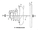
图1第一发明摄像镜头的剖面图Fig. 1 is a sectional view of the camera lens of the first invention
图2第一实施例的摄像镜头的剖面图The sectional view of the imaging lens of the first embodiment of Fig. 2
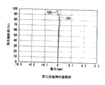
图3第一实施例的摄像镜头的畸变像差图The distortion aberration diagram of the imaging lens of the first embodiment of Fig. 3
图4第一实施例的摄像镜头的像散图The astigmatism diagram of the imaging lens of the first embodiment of Fig. 4
图5第一实施例的摄像镜头的色差/球差图Chromatic aberration/spherical aberration diagram of the imaging lens of the first embodiment of Fig. 5
图6第二实施例的摄像镜头的剖面图The sectional view of the imaging lens of the second embodiment of Fig. 6
图7第二实施例的摄像镜头的畸变像差图The distortion aberration diagram of the imaging lens of the second embodiment of Fig. 7
图8第二实施例的摄像镜头的像散图The astigmatism diagram of the imaging lens of the second embodiment of Fig. 8
图9第二实施例的摄像镜头的色差/球差图Chromatic aberration/spherical aberration diagram of the imaging lens of the second embodiment of Fig. 9
图10第三实施例的摄像镜头的剖面图The sectional view of the imaging lens of the third embodiment of Fig. 10
图11第三实施例的摄像镜头的畸变像差图The distortion aberration diagram of the imaging lens of the third embodiment in Fig. 11
图12第三实施例的摄像镜头的像散图The astigmatism diagram of the imaging lens of the third embodiment of Fig. 12
图13第三实施例的摄像镜头的色差/球差图Chromatic aberration/spherical aberration diagram of the imaging lens of the third embodiment of Fig. 13
图14第四实施例的摄像镜头的剖面图The sectional view of the imaging lens of the fourth embodiment of Fig. 14
图15第四实施例的摄像镜头的畸变像差图The distortion aberration diagram of the imaging lens of the fourth embodiment in Fig. 15
图16第四实施例的摄像镜头的像散图The astigmatism diagram of the imaging lens of the fourth embodiment of Fig. 16
图17第四实施例的摄像镜头的色差/球差图Chromatic aberration/spherical aberration diagram of the imaging lens of the fourth embodiment of Fig. 17
图18第二发明摄像镜头的剖面图Figure 18 is a sectional view of the camera lens of the second invention
图19第五实施例的摄像镜头的剖面图The sectional view of the imaging lens of the fifth embodiment of Fig. 19
图20第五实施例的摄像镜头的畸变像差图Fig. 20 Distortion aberration diagram of the imaging lens of the fifth embodiment
图21第五实施例的摄像镜头的像散图The astigmatism diagram of the imaging lens of the fifth embodiment of Fig. 21
图22第五实施例的摄像镜头的色差/球差图Chromatic aberration/spherical aberration diagram of the imaging lens of the fifth embodiment of Fig. 22
图23第六实施例的摄像镜头的剖面图The sectional view of the imaging lens of the sixth embodiment in Fig. 23
图24第六实施例的摄像镜头的畸变像差图Fig. 24 Distortion aberration diagram of the imaging lens of the sixth embodiment
图25第六实施例的摄像镜头的像散图The astigmatism diagram of the imaging lens of the sixth embodiment of Fig. 25
图26第六实施例的摄像镜头的色差/球差图Chromatic aberration/spherical aberration diagram of the imaging lens of the sixth embodiment of Fig. 26
图27第七实施例的摄像镜头的剖面图The sectional view of the imaging lens of the seventh embodiment of Fig. 27
图28第七实施例的摄像镜头的畸变像差图Fig. 28 Distortion aberration diagram of the imaging lens of the seventh embodiment
图29第七实施例的摄像镜头的像散图The astigmatism diagram of the imaging lens of the seventh embodiment of Fig. 29
图30第七实施例的摄像镜头的色差/球差图Chromatic aberration/spherical aberration diagram of the imaging lens of the seventh embodiment of Fig. 30
图31第八实施例的摄像镜头的剖面图The sectional view of the imaging lens of the eighth embodiment of Fig. 31
图32第八实施例的摄像镜头的畸变像差图Fig. 32 Distortion aberration diagram of the imaging lens of the eighth embodiment
图33第八实施例的摄像镜头的像散图Astigmatism diagram of the imaging lens of the eighth embodiment of Fig. 33
图34第八实施例的摄像镜头的色差/球差图Chromatic aberration/spherical aberration diagram of the imaging lens of the eighth embodiment of Fig. 34
具体实施方式 Detailed ways
以下,参照附图说明本发明的实施例。这些图仅在能帮助理解本发明程度上概括说明部件的形状、大小和配置关系。此外,以下说明中使用的数值以及其他条件仅仅是适当的例子,本发明并不只局限于这些实施例的形式。Hereinafter, embodiments of the present invention will be described with reference to the drawings. These figures only outline the shapes, sizes and arrangements of components to the extent that they can help the understanding of the present invention. In addition, the numerical value and other conditions used in the following description are only suitable examples, and this invention is not limited only to the form of these examples.
图1及图18分别是第一发明及第二发明的摄像镜头的结构图。在图1及图18中定义的表面序号和表面间距等符号,在图2、图6、图10、图14、图19、图23、图27和图31中通用。FIG. 1 and FIG. 18 are structural diagrams of imaging lenses of the first invention and the second invention, respectively. The symbols such as the surface number and surface spacing defined in Fig. 1 and Fig. 18 are commonly used in Fig. 2, Fig. 6, Fig. 10, Fig. 14, Fig. 19, Fig. 23, Fig. 27 and Fig. 31.
从物体侧开始顺次为第一、第二和第三的透镜分别以L1、L2和L3表示,以S1和S2表示孔径光阑。以S1表示设置在第一透镜L1前侧的孔径光阑,而以S2表示设置在第一透镜与第二透镜之间的孔径光阑。The first, second, and third lenses in order from the object side are denoted by L1, L2, and L3, respectively, and the aperture stop is denoted by S1 and S2. An aperture stop provided on the front side of the first lens L1 is denoted by S1, and an aperture stop provided between the first lens and the second lens is denoted by S2.
在不产生误解的情况下,ri(i=1,2,3,...,8)除了作为表示轴上曲率半径的变量之外,还可作为识别透镜,保护玻璃或摄像面的符号(例如,r1用来表示第一透镜的物体侧的表面)。In the absence of misunderstanding, r i (i=1, 2, 3, ..., 8) can be used not only as a variable indicating the radius of curvature on the axis, but also as a symbol for identifying the lens, protective glass or imaging surface (For example, r1 is used to denote the object-side surface of the first lens).
这些图中所示的ri(i=1,2,3,...,8)和di(i=1,2,3,...,7)等参数的具体数值由下面的表1至表8给出。下标i,按照从物体侧到像侧顺序,对应于各透镜的表面序号、透镜的厚度或透镜表面间隔。即,The specific numerical values of parameters such as r i (i=1, 2, 3, ..., 8) and d i (i = 1, 2, 3, ..., 7) shown in these figures are given by the following table 1 to Table 8 are given. The subscript i, in order from the object side to the image side, corresponds to the surface number of each lens, the thickness of the lens, or the lens surface interval. Right now,
ri为第i表面的轴上曲率半径,r i is the radius of curvature on the axis of the i-th surface,
di为第i表面到第(i+1)表面的距离,d i is the distance from the i-th surface to the (i+1)-th surface,
Ni为由第i表面和第(i+1)表面构成的透镜的材料的折射率N i is the refractive index of the lens material composed of the i-th surface and the (i+1)-th surface
vi为由第i表面和第(i+1)表面构成的透镜的材料的阿贝数v i is the Abbe number of the material of the lens composed of the i-th surface and the (i+1)-th surface
图1和图18中,光阑的开口部以线段表示。因为为了定义从镜头面到光阑面的距离,必须明确地表示光阑面与光轴的交点。图2、图6、图10、图14、图19、图23、图27和图31分别是第一实施例至第八实施例的撮像镜头的剖面图,与上述的图1和图18相反,光阑的开口部敞开,以开口部的两端为始点用两条直线代表遮断光线的光阑本身。这是因为为了表示主光线等光线,有必要反映光阑的实际状态,所以把光阑的开口部敞开表示。In FIGS. 1 and 18 , the aperture of the diaphragm is indicated by a line segment. Because in order to define the distance from the lens face to the stop face, the intersection of the stop face and the optical axis must be explicitly indicated. Fig. 2, Fig. 6, Fig. 10, Fig. 14, Fig. 19, Fig. 23, Fig. 27 and Fig. 31 are cross-sectional views of the imaging lenses of the first embodiment to the eighth embodiment respectively, which are opposite to the above-mentioned Fig. 1 and Fig. 18 , the opening of the diaphragm is open, and the diaphragm itself that blocks light is represented by two straight lines starting from the two ends of the opening. This is because it is necessary to reflect the actual state of the diaphragm in order to represent rays such as chief rays, so the opening of the diaphragm is shown open.
光学长L,在第一发明的撮像镜头中,是从光阑S1到摄像面的距离,在第二发明的撮像镜头中,是从第一透镜的物体侧表面与光轴的交点到摄像面的距离。后焦距bf,表示在光轴上的从第三透镜L3的像侧面到摄像面的距离。Optical length L, in the imaging lens of the first invention, is the distance from the diaphragm S1 to the imaging plane, and in the imaging lens of the second invention, is the distance from the intersection of the object-side surface of the first lens and the optical axis to the imaging plane distance. The back focus bf represents the distance on the optical axis from the image side of the third lens L3 to the imaging plane.
在表1至表8的各栏中与表面序号一起表示非球面数据。因为光阑S1、光阑S2的表面及摄像面都是平面,所以其曲率半径以∞表示。In each column of Tables 1 to 8, aspheric surface data are indicated together with surface numbers. Since the surfaces of the diaphragm S1 and the diaphragm S2 and the imaging surface are all planes, their curvature radii are denoted by ∞.
本发明中使用的非球面由下式给出。The aspherical surface used in the present invention is given by the following formula.
Z=ch2/[1+[1-(1+k)c2h2]+1/2]+A0h4+B0h6+C0h8+D0h10 Z=ch 2 /[1+[1-(1+k)c 2 h 2 ] +1/2 ]+A 0 h 4 +B 0 h 6 +C 0 h 8 +D 0 h 10
式中,In the formula,
Z:距表面顶点的切平面的距离Z: the distance from the tangent plane of the surface vertices
c:面的近轴曲率c: Paraxial curvature of the face
h:距光轴的高度h: height from the optical axis
k:圆锥常数k: Conic constant
A0:4级非球面系数A 0 : Grade 4 aspherical coefficient
B0:6级非球面系数B 0 : Grade 6 aspheric coefficient
C0:8级非球面系数C 0 :
D0:10级非球面系数D 0 :
本说明书的表1至表8中,以指数形式表示非球面系数的数值,例如「e-1」代表「10-1」。焦距f值表示,由第1至第3透镜组成的透镜组的组合焦距。In Tables 1 to 8 of this specification, the values of the aspheric coefficients are expressed in exponential form, for example, "e-1" represents "10 -1 ". The focal length f value represents the combined focal length of the lens group consisting of the first to third lenses.
下面参照图1至图17分别说明第一至第四实施例,参照图18至图34分别说明第五至第八实施例。Next, the first to fourth embodiments will be described with reference to FIGS. 1 to 17, and the fifth to eighth embodiments will be described with reference to FIGS. 18 to 34, respectively.
图3、图7、图11、图15、图20、图24、图28和图32表示畸变像差,按照相应的至光轴的距离(纵轴)表示像差量(横轴),纵轴采用百分率表示,其中像面内距光轴的最大距离为100,横轴采用百分率表示正切条件的不满足量。图4、图8、图12、图16、图21、图25、图29和图33表示像散,像散曲线与畸变像差曲线相同,对应于纵轴所示的至光轴的距离,横轴表示其像差量(mm单位),图中分别表示了子午面(meridional)和弧矢面(sagittal)的像差量(mm单位)。图5、图9、图13、图17、图22、图26、图30和图34表示色差/球差,在色差/球差曲线中,纵轴为入射高h(F数值),而相应的像差量(mm单位)以横轴表示。Fig. 3, Fig. 7, Fig. 11, Fig. 15, Fig. 20, Fig. 24, Fig. 28 and Fig. 32 show the distortion aberration, and the aberration amount (horizontal axis) is represented according to the corresponding distance (vertical axis) to the optical axis, and the vertical The axis is expressed as a percentage, and the maximum distance from the optical axis in the image plane is 100, and the horizontal axis is expressed as a percentage to indicate the unsatisfied amount of the tangent condition. Figure 4, Figure 8, Figure 12, Figure 16, Figure 21, Figure 25, Figure 29 and Figure 33 show astigmatism, the astigmatism curve is the same as the distortion aberration curve, corresponding to the distance to the optical axis shown on the vertical axis, The abscissa indicates the amount of aberration (unit of mm), and the figure shows the amount of aberration (unit of mm) of the meridional plane (meridional) and the sagittal plane (sagittal) respectively. Figure 5, Figure 9, Figure 13, Figure 17, Figure 22, Figure 26, Figure 30 and Figure 34 show chromatic aberration/spherical aberration, in the chromatic aberration/spherical aberration curve, the vertical axis is the incident height h (F value), and the corresponding The aberration amount (mm unit) is shown on the horizontal axis.
另外,色差/球差曲线中,示明了相对于C线(波长656.3nm的光),d线(波长587.6nm的光),e线(波长546.1nm的光),F线(波长486.1nm的光)以及g线(波长435.8nm的光)的像差量。折射率为相对于d线(587.6nm的光)的折射率。In addition, the chromatic aberration/spherical aberration curve shows the C line (light with a wavelength of 656.3nm), the d line (light with a wavelength of 587.6nm), the e line (light with a wavelength of 546.1nm), and the F line (light with a wavelength of 486.1nm). light) and g-line (light with a wavelength of 435.8nm) aberrations. The refractive index is the refractive index with respect to the d-line (light of 587.6 nm).
以下,由表1至表8汇总给出第一至第八实施例中的有关透镜部件的曲率半径(mm单位)、透镜表面间距(mm单位)、透镜材料的折射率、透镜材料的阿贝数、焦距、F数值和非球面系数。在第一至第八实施例中,各别以f1、f2和f3表示第一透镜L1、第二透镜L2和第三透镜L3的焦距。在第一至第八实施例的所有实施例中,f1取正值,而f2和f3取负值。即,第一透镜L1是具有正的屈光力的透镜,而第二透镜L2及第三透镜L3是具有负的屈光力的透镜。并且,摄像镜头的组合焦距f以1.00mm归一化。Below, the radius of curvature (mm unit), the lens surface distance (mm unit), the refractive index of the lens material, and the Abbe of the lens material in the first to eighth embodiments are summarized by Table 1 to Table 8. number, focal length, F-number and aspheric coefficient. In the first to eighth embodiments, the focal lengths of the first lens L1, the second lens L2, and the third lens L3 are denoted by f1, f2, and f3, respectively. In all of the first to eighth embodiments, f1 takes positive values, and f2 and f3 take negative values. That is, the first lens L1 is a lens having positive refractive power, and the second lens L2 and the third lens L3 are lenses having negative refractive power. Also, the combined focal length f of the imaging lens is normalized to 1.00 mm.
另外,光轴上曲率半径ri(i=1,2,3,...,8),在物体侧呈凸面时取正值,在像侧呈凸面时取负值。由构成镜头的曲面的曲率半径的取值符号可知,第一透镜L1是物体侧及像侧均呈凸面的凸透镜;第二透镜L2是像侧呈凸面的弯月形透镜;第三透镜L3是物体侧及像侧均呈凸面的凸透镜。In addition, the radius of curvature r i (i=1, 2, 3, ..., 8) on the optical axis takes a positive value when the object side is convex, and takes a negative value when the image side is convex. From the sign of the radius of curvature of the curved surface that constitutes the lens, it can be seen that the first lens L1 is a convex lens with convex surfaces on both the object side and the image side; the second lens L2 is a meniscus lens with a convex surface on the image side; the third lens L3 is A convex lens with convex surfaces on both the object side and the image side.
下面说明各实施例的特征。第一至第八实施例中,第一透镜L1和第三透镜L3采用环烯塑料ZEONEX E48R(ZEONEX是日本zeon股份有限公司的注册商标,而E48R是产品编号)为材料。而第二透镜L2采用芴类聚酯或聚碳酸酯为材料。Features of each embodiment will be described below. In the first to eighth embodiments, the first lens L1 and the third lens L3 are made of cycloolefin plastic ZEONEX E48R (ZEONEX is a registered trademark of Japan Zeon Co., Ltd., and E48R is a product number). The second lens L2 is made of fluorene polyester or polycarbonate.
ZEONEX E48R相对于d线的折射率是1.5304,而芴类聚酯和聚碳酸酯相对于d线的折射率分别是1.607和1.5830。ZEONEXE48R的阿贝数是56.0,而芴类聚酯和聚碳酸酯的阿贝数分别是27.0和30.0。The refractive index of ZEONEX E48R relative to the d-line is 1.5304, while the refractive indices of fluorene polyester and polycarbonate relative to the d-line are 1.607 and 1.5830, respectively. The Abbe number of ZEONEXE48R is 56.0, while the Abbe numbers of fluorene-based polyester and polycarbonate are 27.0 and 30.0, respectively.
而且,第一透镜L1的两面、第二透镜L2的两面,以及第三透镜L3的两面为非球面。Furthermore, both surfaces of the first lens L1, both surfaces of the second lens L2, and both surfaces of the third lens L3 are aspherical surfaces.
【第一发明】【The first invention】
第一发明的摄像镜头如图1所示,具有孔径光阑S1、第一透镜L1、第二透镜L2和第三透镜L3,按照从物体侧到像侧,由孔径光阑S1、第一透镜L1、第二透镜L2和第三透镜L3的顺序构成。以下在表1至表4中汇总了第一发明的摄像镜头的第一至第四实施例中,有关透镜部件的曲率半径(mm单位)、透镜表面间距(mm单位)、透镜材料的折射率、透镜材料的阿贝数、焦距、F数值和非球面系数。在表1至表4中,第二透镜L2到第三透镜L3的光轴上的间距D对应于d5。The imaging lens of the first invention is shown in Figure 1, has aperture stop S1, the first lens L1, the second lens L2 and the 3rd lens L3, according to from object side to image side, by aperture stop S1, first lens L1, the second lens L2, and the third lens L3 are sequentially constituted. In the first to fourth embodiments of the imaging lens of the first invention, the radius of curvature (mm unit), the lens surface distance (mm unit), and the refractive index of the lens material are summarized below in Tables 1 to 4. , Abbe number, focal length, F value and aspheric coefficient of the lens material. In Tables 1 to 4, the distance D on the optical axis of the second lens L2 to the third lens L3 corresponds to d 5 .


【第一实施例】【The first embodiment】
第一透镜L1和第三透镜L3采用ZEONEX E48R为材料,第二透镜L2采用芴类聚酯EP-4000(EP-4000是三菱瓦斯化学股份有限公司的产品编号)为材料。The first lens L1 and the third lens L3 are made of ZEONEX E48R, and the second lens L2 is made of fluorene polyester EP-4000 (EP-4000 is a product number of Mitsubishi Gas Chemical Co., Ltd.).
(A)第一透镜L1的物体侧曲率半径r2=0.356mm(A) The object-side curvature radius r2 of the first lens L1 = 0.356 mm
(B)第一透镜L1的像侧曲率半径r3=-17.782mm(B) Image-side curvature radius r3 of the first lens L1 = -17.782mm
(C)第二透镜L2和第三透镜L3的光轴上的间隔D(=d5)=0.1000mm(C) Interval D (= d 5 ) on the optical axis of the second lens L2 and the third lens L3 = 0.1000 mm
(D)光学长L=1.121mm(D) Optical length L=1.121mm
(E)像高(有效画面的对角线长)2Y=2×0.64=1.28mm(E) Image height (diagonal length of effective screen) 2Y=2×0.64=1.28mm
(F)第一透镜L1的焦距f1=0.66mm(F) The focal length f1 of the first lens L1=0.66mm
因此:therefore:
|r2/r3|=|0.356/-17.782|=0.020|r2/r3|=|0.356/-17.782|=0.020
D/f=0.1000/1.00=0.1000D/f=0.1000/1.00=0.1000
L/(2Y)=1.121/1.28=0.876L/(2Y)=1.121/1.28=0.876
f1/f=0.66/1.00=0.66f1/f=0.66/1.00=0.66
所以第一实施例中的透镜组,满足下面所有的条件式(1-1)至(1-4)。Therefore, the lens group in the first embodiment satisfies all of the following conditional expressions (1-1) to (1-4).
0.01<|r2/r3|<0.05 (1-1)0.01<|r2/r3|<0.05 (1-1)
0.05<D/f≤0.1 (1-2)0.05<D/f≤0.1 (1-2)
0.6<L/(2Y)<0.9 (1-3)0.6<L/(2Y)<0.9 (1-3)
0.5<f1/f<0.7 (1-4)0.5<f1/f<0.7 (1-4)
下文中提及的第一发明的条件式指上述(1-1)至(1-4)的四个条件式。The conditional expressions of the first invention mentioned hereinafter refer to the four conditional expressions (1-1) to (1-4) above.
光阑S1如表1所示,设于第一透镜L1第1面(物体侧的面)与光轴的交点处。因光阑面是平面,由表1中r1=∞,可知光阑S1设置于r1处。另外,F数值为3.4。As shown in Table 1, the stop S1 is provided at the intersection of the first surface (object-side surface) of the first lens L1 and the optical axis. Because the diaphragm surface is a plane, r1=∞ in Table 1, it can be seen that the diaphragm S1 is set at r1. In addition, the F value was 3.4.
图2示明第一实施例的摄像镜头的剖面图。相对于焦距1.00mm,后焦距为0.389mm,因此能确保充分的长度。FIG. 2 shows a cross-sectional view of the imaging lens of the first embodiment. Compared with the focal length of 1.00mm, the back focal length is 0.389mm, so sufficient length can be secured.
图3示明畸变像差曲线20,图4示明像散曲线(对子午面(meridional)的像差曲线22和对弧矢面(sagittal)的像差曲线24),而图5示明色差/球差曲线(相对于C线的像差曲线26,相对于d线的像差曲线28,相对于e线的像差曲线30,相对于F线的像差曲线32和相对于g线的像差曲线34)。Fig. 3 shows the
图3和图4的像差曲线的纵轴,以到光轴距离的百分比值表示像高。图3和图4中,100%对应于0.640mm。另外,图5的像差曲线的纵轴表示入射高h(F数),最大对应于3.4,横轴表示像差量的大小。The vertical axis of the aberration curves in Figure 3 and Figure 4 represents the image height as a percentage of the distance from the optical axis. In Figures 3 and 4, 100% corresponds to 0.640mm. In addition, the vertical axis of the aberration curve in FIG. 5 represents the incident height h (F-number), which corresponds to 3.4 at the maximum, and the horizontal axis represents the magnitude of the aberration amount.
畸变像差在像高60%(像高0.384mm)处,像差量的绝对值达到最大为0.2640%。而像高小于0.640mm时,其像差量的绝对值均小于0.2640%。Distortion aberration At an image height of 60% (image height 0.384mm), the absolute value of the aberration amount reaches a maximum of 0.2640%. When the image height is less than 0.640mm, the absolute value of the aberration is less than 0.2640%.
像散在像高100%(像高0.640mm)处,对子午面(meridional)的像差量的绝对值达到最大为0.0513mm。而像高小于0.640mm时,其像差量的绝对值均小于0.0513mm。Astigmatism is at an image height of 100% (image height 0.640 mm), and the absolute value of the aberration amount with respect to the meridional plane (meridional) reaches a maximum of 0.0513 mm. When the image height is less than 0.640mm, the absolute value of the aberration is less than 0.0513mm.
色差/球差在入射高h为30%处,相对于g线的像差曲线34的像差量的绝对值达到最大为0.0114mm,像差量的绝对值在0.0114mm以内。Chromatic aberration/spherical aberration When the incident height h is 30%, the absolute value of the aberration amount relative to the g-
【第二实施例】【Second Embodiment】
第一透镜L1和第三透镜L3采用ZEONEX E48R为材料,第二透镜L2采用聚碳酸酯为材料。The first lens L1 and the third lens L3 are made of ZEONEX E48R, and the second lens L2 is made of polycarbonate.
(A)第一透镜L1的物体侧曲率半径r2=0.356mm(A) The object-side curvature radius r2 of the first lens L1 = 0.356 mm
(B)第一透镜L1的像侧曲率半径r3=-17.782mm(B) Image-side curvature radius r3 of the first lens L1 = -17.782mm
(C)第二透镜L2和第三透镜L3的光轴上的间隔D(=d5)=0.1000mm(C) Interval D (= d 5 ) on the optical axis of the second lens L2 and the third lens L3 = 0.1000 mm
(D)光学长L=1.119mm(D) Optical length L=1.119mm
(E)像高(有效画面的对角线长)2Y=2×0.64=1.28mm(E) Image height (diagonal length of effective screen) 2Y=2×0.64=1.28mm
(F)第一透镜L1的焦距f1=0.66mm(F) The focal length f1 of the first lens L1=0.66mm
因此:therefore:
|r2/r3|=|0.356/-17.782|=0.020|r2/r3|=|0.356/-17.782|=0.020
D/f=0.1000/1.00=0.1000D/f=0.1000/1.00=0.1000
L/(2Y)=1.119/1.28=0.874L/(2Y)=1.119/1.28=0.874
f1/f=0.66/1.00=0.66f1/f=0.66/1.00=0.66
所以第二实施例中的透镜组,满足下面所有的条件式(1-1)至(1-4)。Therefore, the lens group in the second embodiment satisfies all of the following conditional expressions (1-1) to (1-4).
0.01<|r2/r3|<0.05 (1-1)0.01<|r2/r3|<0.05 (1-1)
0.05<D/f≤0.1 (1-2)0.05<D/f≤0.1 (1-2)
0.6<L/(2Y)<0.9 (1-3)0.6<L/(2Y)<0.9 (1-3)
0.5<f1/f<0.7 (1-4)0.5<f1/f<0.7 (1-4)
下文中提及的第一发明的条件式指上述(1-1)至(1-4)的四个条件式。The conditional expressions of the first invention mentioned hereinafter refer to the four conditional expressions (1-1) to (1-4) above.
光阑S1如表2所示,设于第一透镜L1第1面(物体侧的面)与光轴的交点处。因光阑面是平面,由表2中r1=∞,可知光阑S1设置于r1处。另外,F数值为3.4。As shown in Table 2, the stop S1 is provided at the intersection of the first surface (object-side surface) of the first lens L1 and the optical axis. Because the diaphragm surface is a plane, from r1=∞ in Table 2, it can be seen that the diaphragm S1 is set at r1. In addition, the F value was 3.4.
图6示明第二实施例的摄像镜头的剖面图。相对于焦距1.00mm,后焦距为0.386mm,因此能确保充分的长度。FIG. 6 shows a cross-sectional view of the imaging lens of the second embodiment. Compared with the focal length of 1.00mm, the back focal length is 0.386mm, so sufficient length can be secured.
图7示明畸变像差曲线36,图8示明像散曲线(对子午面(meridional)的像差曲线38和对弧矢面(sagittal)的像差曲线40),而图9示明色差/球差曲线(相对于C线的像差曲线42,相对于d线的像差曲线44,相对于e线的像差曲线46,相对于F线的像差曲线48和相对于g线的像差曲线50)。Fig. 7 shows the
图7和图8的像差曲线的纵轴,以到光轴距离的百分比值表示像高。图7和图8中,100%对应于0.640mm。另外,图9的像差曲线的纵轴表示入射高h(F数),最大对应于3.4,横轴表示像差量的大小。The vertical axis of the aberration curves in Figures 7 and 8 represents the image height as a percentage of the distance from the optical axis. In Figures 7 and 8, 100% corresponds to 0.640mm. In addition, the vertical axis of the aberration curve in FIG. 9 represents the incident height h (F-number), which corresponds to 3.4 at the maximum, and the horizontal axis represents the magnitude of the aberration amount.
畸变像差在像高60%(像高0.384mm)处,像差量的绝对值达到最大为0.2203%。而像高小于0.640mm时,其像差量的绝对值均小于0.2203%。Distortion aberration At an image height of 60% (image height 0.384mm), the absolute value of the aberration amount reaches a maximum of 0.2203%. When the image height is less than 0.640mm, the absolute value of the aberration is less than 0.2203%.
像散在像高100%(像高0.640mm)处,对子午面(meridional)的像差量的绝对值达到最大为0.0234mm。而像高小于0.640mm时,其像差量的绝对值均小于0.0234mm。Astigmatism is at an image height of 100% (image height 0.640mm), and the absolute value of the aberration amount with respect to the meridional plane (meridional) reaches a maximum of 0.0234mm. When the image height is less than 0.640mm, the absolute value of the aberration is less than 0.0234mm.
色差/球差在入射高h为30%处,相对于g线的像差曲线50的像差量的绝对值达到最大为0.0129mm,像差量的绝对值在0.0129mm以内。Chromatic aberration/spherical aberration When the incident height h is 30%, the absolute value of the aberration amount relative to the g-
【第三实施例】[Third embodiment]
第一透镜L1和第三透镜L3采用ZEONEX E48R为材料,第二透镜L2采用聚碳酸酯为材料。The first lens L1 and the third lens L3 are made of ZEONEX E48R, and the second lens L2 is made of polycarbonate.
(A)第一透镜L1的物体侧曲率半径r2=0.356mm(A) The object-side curvature radius r2 of the first lens L1 = 0.356 mm
(B)第一透镜L1的像侧曲率半径r3=-8.887mm(B) Image-side curvature radius r3 of the first lens L1 = -8.887mm
(C)第二透镜L2和第三透镜L3的光轴上的间隔D(=d5)=0.08mm(C) Interval D (= d 5 ) on the optical axis of the second lens L2 and the third lens L3 = 0.08 mm
(D)光学长L=1.092mm(D) Optical length L=1.092mm
(E)像高(有效画面的对角线长)2Y=2×0.64=1.28mm(E) Image height (diagonal length of effective screen) 2Y=2×0.64=1.28mm
(F)第一透镜L1的焦距f1=0.65mm(F) The focal length f1 of the first lens L1=0.65mm
因此:therefore:
|r2/r3|=|0.356/-8.887|=0.04|r2/r3|=|0.356/-8.887|=0.04
D/f=0.08/1.00=0.08D/f=0.08/1.00=0.08
L/(2Y)=1.092/1.28=0.8531L/(2Y)=1.092/1.28=0.8531
f1/f=0.65/1.00=0.65f1/f=0.65/1.00=0.65
所以第三实施例中的透镜组,满足下面所有的条件式(1-1)至(1-4)。Therefore, the lens group in the third embodiment satisfies all of the following conditional expressions (1-1) to (1-4).
0.01<|r2/r3|<0.05 (1-1)0.01<|r2/r3|<0.05 (1-1)
0.05<D/f≤0.1 (1-2)0.05<D/f≤0.1 (1-2)
0.6<L/(2Y)<0.9 (1-3)0.6<L/(2Y)<0.9 (1-3)
0.5<f1/f<0.7 (1-4)0.5<f1/f<0.7 (1-4)
下文中提及的第一发明的条件式是指上述(1-1)至(1-4)的四个条件式。The conditional expressions of the first invention mentioned hereinafter refer to the four conditional expressions of (1-1) to (1-4) above.
光阑S1如表3所示,设于第一透镜L1第1面(物体侧的面)与光轴的交点处。因光阑面是平面,由表3中r1=∞,可知光阑S1设置于r1处。另外,F数值为3.4。As shown in Table 3, the stop S1 is provided at the intersection of the first surface (object-side surface) of the first lens L1 and the optical axis. Since the diaphragm surface is a plane, r1=∞ in Table 3, it can be seen that the diaphragm S1 is set at r1. In addition, the F value was 3.4.
图10示明第三实施例的摄像镜头的剖面图。相对于焦距1.00mm,后焦距为0.381mm,因此能确保充分的长度。FIG. 10 shows a cross-sectional view of the imaging lens of the third embodiment. Compared with the focal length of 1.00mm, the back focal length is 0.381mm, so sufficient length can be secured.
图11示明畸变像差曲线52,图12示明像散曲线(对子午面(meridional)的像差曲线54和对弧矢面(sagittal)的像差曲线56),而图13示明色差/球差曲线(相对于C线的像差曲线58,相对于d线的像差曲线60,相对于e线的像差曲线62,相对于F线的像差曲线64和相对于g线的像差曲线66)。Fig. 11 shows distortion aberration curve 52, Fig. 12 shows astigmatism curve (
图11和图12的像差曲线的纵轴,以到光轴距离的百分比值表示像高。图11和图12中,100%对应于0.640mm。另外,图13的像差曲线的纵轴表示入射高h(F数),最大对应于3.4,横轴表示像差量的大小。The vertical axis of the aberration curves in Figure 11 and Figure 12 represents the image height as a percentage of the distance from the optical axis. In Figures 11 and 12, 100% corresponds to 0.640 mm. In addition, the vertical axis of the aberration curve in FIG. 13 represents the incident height h (F-number), which corresponds to 3.4 at the maximum, and the horizontal axis represents the magnitude of the aberration amount.
畸变像差在像高100%(像高0.640mm)处,像差量的绝对值达到最大为0.5710%。而像高小于0.640mm时,其像差量的绝对值均小于0.5710%。Distortion aberration At an image height of 100% (image height 0.640 mm), the absolute value of the aberration amount reaches a maximum of 0.5710%. When the image height is less than 0.640mm, the absolute value of the aberration is less than 0.5710%.
像散在像高100%(像高0.640mm)处,对子午面(meridional)的像差量的绝对值达到最大为0.0115mm。而像高小于0.640mm时,其像差量的绝对值均小于0.0115mm。Astigmatism is at an image height of 100% (image height 0.640 mm), and the absolute value of the aberration amount on the meridional plane (meridional) reaches a maximum of 0.0115 mm. When the image height is less than 0.640mm, the absolute value of the aberration is less than 0.0115mm.
色差/球差在入射高h为30%处,相对于g线的像差曲线66的像差量的绝对值达到最大为0.0154mm,像差量的绝对值在0.0154mm以内。For chromatic aberration/spherical aberration, when the incident height h is 30%, the absolute value of the aberration amount relative to the g-
【第四实施例】[Fourth embodiment]
第一透镜L1和第三透镜L3采用ZEONEX E48R为材料,第二透镜L2采用聚碳酸酯为材料。The first lens L1 and the third lens L3 are made of ZEONEX E48R, and the second lens L2 is made of polycarbonate.
(A)第一透镜L1的物体侧曲率半径r2=0.356mm(A) The object-side curvature radius r2 of the first lens L1 = 0.356 mm
(B)第一透镜L1的像侧曲率半径r3=-8.887mm(B) Image-side curvature radius r3 of the first lens L1 = -8.887mm
(C)第二透镜L2和第三透镜L3的光轴上的间隔D(=d5)=0.0511mm(C) Distance D (= d 5 ) on the optical axis of the second lens L2 and the third lens L3 = 0.0511 mm
(D)光学长L=1.1043mm(D) Optical length L=1.1043mm
(E)像高(有效画面的对角线长)2Y=2×0.64=1.28mm(E) Image height (diagonal length of effective screen) 2Y=2×0.64=1.28mm
(F)第一透镜L1的焦距f1=0.65mm(F) The focal length f1 of the first lens L1=0.65mm
因此:therefore:
|r2/r3|=|0.356/-8.887|=0.04|r2/r3|=|0.356/-8.887|=0.04
D/f=0.0511/1.00=0.0511D/f=0.0511/1.00=0.0511
L/(2Y)=1.104/1.28=0.8627L/(2Y)=1.104/1.28=0.8627
f1/f=0.65/1.00=0.65f1/f=0.65/1.00=0.65
所以第四实施例中的透镜组,满足下面所有的条件式(1-1)至(1-4)。Therefore, the lens group in the fourth embodiment satisfies all of the following conditional expressions (1-1) to (1-4).
0.01<|r2/r3|<0.05 (1-1)0.01<|r2/r3|<0.05 (1-1)
0.05<D/f≤0.1 (1-2)0.05<D/f≤0.1 (1-2)
0.6<L/(2Y)<0.9 (1-3)0.6<L/(2Y)<0.9 (1-3)
0.5<f1/f<0.7 (1-4)0.5<f1/f<0.7 (1-4)
下文中提及的第一发明的条件式是指上述(1-1)至(1-4)的四个条件式。The conditional expressions of the first invention mentioned hereinafter refer to the four conditional expressions of (1-1) to (1-4) above.
光阑S1如表4所示,设于第一透镜L1第1面(物体侧的面)与光轴的交点处。因光阑面是平面,由表4中r1=∞,可知光阑S1设置于r1处。另外,F数值为3.4。As shown in Table 4, the stop S1 is provided at the intersection of the first surface (object-side surface) of the first lens L1 and the optical axis. Since the diaphragm surface is a plane, from r1=∞ in Table 4, it can be seen that the diaphragm S1 is set at r1. In addition, the F value was 3.4.
图14示明第四实施例的摄像镜头的剖面图。相对于焦距1.00mm,后焦距为0.422mm,因此能确保充分的长度。FIG. 14 shows a cross-sectional view of the imaging lens of the fourth embodiment. Compared with the focal length of 1.00mm, the back focus is 0.422mm, so sufficient length can be secured.
图15示明畸变像差曲线68,图16示明像散曲线(对子午面(meridional)的像差曲线70和对弧矢面(sagittal)的像差曲线72),而图17示明色差/球差曲线(相对于C线的像差曲线74,相对于d线的像差曲线76,相对于e线的像差曲线78,相对于F线的像差曲线80和相对于g线的像差曲线82)。Fig. 15 shows the
图15和图16的像差曲线的纵轴,以到光轴距离的百分比值表示像高。图15和图16中,100%对应于0.639mm。另外,图17的像差曲线的纵轴表示入射高h(F数),最大对应于3.4,横轴表示像差量的大小。The vertical axis of the aberration curves in Fig. 15 and Fig. 16 represents the image height as a percentage of the distance from the optical axis. In Fig. 15 and Fig. 16, 100% corresponds to 0.639 mm. In addition, the vertical axis of the aberration curve in FIG. 17 represents the incident height h (F-number), which corresponds to 3.4 at the maximum, and the horizontal axis represents the magnitude of the aberration amount.
畸变像差在像高100%(像高0.639mm)处,像差量的绝对值达到最大为0.5428%。而像高小于0.639mm时,其像差量的绝对值均小于0.5428%。Distortion aberration At an image height of 100% (image height 0.639 mm), the absolute value of the aberration amount reaches a maximum of 0.5428%. When the image height is less than 0.639mm, the absolute value of the aberration is less than 0.5428%.
像散在像高80%(像高0.512mm)处,对子午面(meridional)的像差量的绝对值达到最大为0.0512mm。而像高小于0.639mm时,其像差量的绝对值均小于0.0512mm。Astigmatism is 80% of the image height (image height 0.512 mm), and the absolute value of the aberration amount with respect to the meridional plane (meridional) reaches a maximum of 0.0512 mm. When the image height is less than 0.639mm, the absolute value of the aberration is less than 0.0512mm.
色差/球差在入射高h为30%处,相对于g线的像差曲线82的像差量的绝对值达到最大为0.0153mm,像差量的绝对值在0.0153mm以内。For chromatic aberration/spherical aberration, when the incident height h is 30%, the absolute value of the aberration amount relative to the g-
【第二发明】【Second Invention】
第二发明的摄像镜头如图18所示,具有第一透镜L1、孔径光阑S2、第二透镜L2和第三透镜L3,按照从物体侧到像侧,由第一透镜L1、孔径光阑S2、第二透镜L2和第三透镜L3的顺序构成。以下在表5至表8中汇总了第二发明的摄像镜头的第五至第八实施例的,有关透镜部件的曲率半径(mm单位)、透镜表面间距(mm单位)、透镜材料的折射率、透镜材料的阿贝数、焦距、F数值和非球面系数。在表5至表8中,第二透镜L2到第三透镜L3的光轴上的间距D对应于d5.The imaging lens of the second invention has a first lens L1, an aperture stop S2, a second lens L2, and a third lens L3 as shown in FIG. S2, the second lens L2 and the third lens L3 are formed in sequence. The fifth to eighth embodiments of the imaging lens of the second invention are summarized below in Tables 5 to 8, regarding the radius of curvature (mm unit) of the lens components, the lens surface distance (mm unit), and the refractive index of the lens material , Abbe number, focal length, F value and aspheric coefficient of the lens material. In Table 5 to Table 8, the distance D on the optical axis of the second lens L2 to the third lens L3 corresponds to d 5 .


【第五实施例】[fifth embodiment]
第一透镜L1和第三透镜L3采用ZEONEX E48R为材料,第二透镜L2采用芴类聚酯EP-4000(EP-4000是三菱瓦斯化学股份有限公司的产品编号)为材料。The first lens L1 and the third lens L3 are made of ZEONEX E48R, and the second lens L2 is made of fluorene polyester EP-4000 (EP-4000 is a product number of Mitsubishi Gas Chemical Co., Ltd.).
(A)第一透镜L1的物体侧曲率半径r1=0.356mm(A) The object-side curvature radius r1 of the first lens L1 = 0.356 mm
(B)第一透镜L1的像侧曲率半径r2=-17.782mm(B) Image-side curvature radius r2 of the first lens L1 = -17.782mm
(C)第二透镜L2和第三透镜L3的光轴上的间隔D=0.1000mm(C) The distance D on the optical axis of the second lens L2 and the third lens L3 = 0.1000mm
(D)光学长L=1.1208mm(D) Optical length L=1.1208mm
(E)像高(有效画面的对角线长)2Y=2×0.64=1.28mm(E) Image height (diagonal length of effective screen) 2Y=2×0.64=1.28mm
(F)第一透镜L1的焦距f1=0.66mm(F) The focal length f1 of the first lens L1=0.66mm
因此:therefore:
|r1/r2|=|0.356/-17.782|=0.020|r1/r2|=|0.356/-17.782|=0.020
D/f=0.1000/1.00=0.1000D/f=0.1000/1.00=0.1000
L/(2Y)=1.121/1.28=0.8756L/(2Y)=1.121/1.28=0.8756
f1/f=0.66/1.00=0.66f1/f=0.66/1.00=0.66
所以第五实施例中的透镜组,满足下面所有的条件式(2-1)至(2-4)。Therefore, the lens group in the fifth embodiment satisfies all of the following conditional expressions (2-1) to (2-4).
0.01<|r1/r2|<0.05 (2-1)0.01<|r1/r2|<0.05 (2-1)
0.05<D/f≤0.1 (2-2)0.05<D/f≤0.1 (2-2)
0.6<L/(2Y)<0.9 (2-3)0.6<L/(2Y)<0.9 (2-3)
0.5<f1/f<0.7 (2-4)0.5<f1/f<0.7 (2-4)
下文中提及的第二发明的条件式是指上述(2-1)至(2-4)的四个条件式。The conditional expressions of the second invention mentioned hereinafter refer to the four conditional expressions of (2-1) to (2-4) above.
光阑S2如表5所示,设于第一透镜L1与第一透镜L2之间。因光阑面是平面,由表5中r3=∞,可知光阑S2设置于r3处。另外,F数值为3.4。As shown in Table 5, the stop S2 is provided between the first lens L1 and the first lens L2. Since the diaphragm surface is a plane, r3=∞ in Table 5, it can be seen that the diaphragm S2 is set at r3. In addition, the F value was 3.4.
图19示明第五实施例的摄像镜头的剖面图。相对于焦距1.00mm,后焦距为0.389mm,因此能确保充分的长度。FIG. 19 shows a cross-sectional view of the imaging lens of the fifth embodiment. Compared with the focal length of 1.00mm, the back focal length is 0.389mm, so sufficient length can be secured.
图20示明畸变像差曲线120,图21示明像散曲线(对子午面(meridional)的像差曲线122和对弧矢面(sagittal)的像差曲线124),而图22示明色差/球差曲线(相对于C线的像差曲线126,相对于d线的像差曲线128,相对于e线的像差曲线130,相对于F线的像差曲线132和相对于g线的像差曲线134)。Fig. 20 shows the distortion curve 120, Fig. 21 shows the astigmatism curve (the aberration curve 122 for the meridional plane (meridional) and the
图20和图21的像差曲线的纵轴,以到光轴距离的百分比值表示像高。图24和图25中,100%对应于0.640mm。另外,图22的像差曲线的纵轴表示入射高h(F数),最大对应于3.4,横轴表示像差量的大小。The vertical axis of the aberration curves in Fig. 20 and Fig. 21 represents the image height as a percentage of the distance from the optical axis. In Fig. 24 and Fig. 25, 100% corresponds to 0.640 mm. In addition, the vertical axis of the aberration curve in FIG. 22 represents the incident height h (F-number), which corresponds to 3.4 at the maximum, and the horizontal axis represents the magnitude of the aberration amount.
畸变像差在像高60%(像高0.384mm)处,像差量的绝对值达到最大为0.3310%。而像高小于0.640mm时,其像差量的绝对值均小于0.3310%。Distortion aberration At an image height of 60% (image height 0.384 mm), the absolute value of the aberration amount reaches a maximum of 0.3310%. When the image height is less than 0.640mm, the absolute value of the aberration is less than 0.3310%.
像散在像高100%(像高0.640mm)处,对弧矢面(sagittal)的像差量的绝对值达到最大为0.0196mm。而像高小于0.640mm时,其像差量的绝对值均小于0.0196mm。Astigmatism is at 100% of the image height (image height 0.640 mm), and the absolute value of the aberration amount with respect to the sagittal plane reaches a maximum of 0.0196 mm. When the image height is less than 0.640mm, the absolute value of the aberration is less than 0.0196mm.
色差/球差在入射高h为30%处,相对于g线的像差曲线134的像差量的绝对值达到最大为0.0114mm,像差量的绝对值在0.0114mm以内。For chromatic aberration/spherical aberration, when the incident height h is 30%, the absolute value of the aberration amount relative to the g-
【第六实施例】[Sixth embodiment]
第一透镜L1和第三透镜L3采用ZEONEX E48R为材料,第二透镜L2采用聚碳酸酯为材料。The first lens L1 and the third lens L3 are made of ZEONEX E48R, and the second lens L2 is made of polycarbonate.
(A)第一透镜L1的物体侧曲率半径r1=0.3566mm(A) The object-side curvature radius r1 of the first lens L1 = 0.3566 mm
(B)第一透镜L1的像侧曲率半径r2=-17.782mm(B) Image-side curvature radius r2 of the first lens L1 = -17.782 mm
(C)第二透镜L2和第三透镜L3的光轴上的间隔D=0.1000mm(C) The distance D on the optical axis of the second lens L2 and the third lens L3 = 0.1000mm
(D)光学长L=1.119mm(D) Optical length L=1.119mm
(E)像高(有效画面的对角线长)2Y=2×0.64=1.28mm(E) Image height (diagonal length of effective screen) 2Y=2×0.64=1.28mm
(F)第一透镜L1的焦距f1=0.66mm(F) The focal length f1 of the first lens L1=0.66mm
因此:therefore:
|r1/r2|=|0.356/-17.782|=0.020|r1/r2|=|0.356/-17.782|=0.020
D/f=0.1000/1.00=0.1000D/f=0.1000/1.00=0.1000
L/(2Y)=1.119/1.28=0.874L/(2Y)=1.119/1.28=0.874
f1/f=0.66/1.00=0.66f1/f=0.66/1.00=0.66
所以第六实施例中的透镜组,满足下面所有的条件式(2-1)至(2-4)。Therefore, the lens group in the sixth embodiment satisfies all of the following conditional expressions (2-1) to (2-4).
0.01<|r1/r2|<0.05 (2-1)0.01<|r1/r2|<0.05 (2-1)
0.05<D/f≤0.1 (2-2)0.05<D/f≤0.1 (2-2)
0.6<L/(2Y)<0.9 (2-3)0.6<L/(2Y)<0.9 (2-3)
0.5<f1/f<0.7 (2-4)0.5<f1/f<0.7 (2-4)
下文中提及的第二发明的条件式是指上述(2-1)至(2-4)的四个条件式。The conditional expressions of the second invention mentioned hereinafter refer to the four conditional expressions of (2-1) to (2-4) above.
光阑S2如表6所示,设于第一透镜L1与第一透镜L2之间。因光阑面是平面,由表6中r3=∞,可知光阑S2设置于r3处。另外,F数值为3.4。As shown in Table 6, the stop S2 is provided between the first lens L1 and the first lens L2. Since the diaphragm surface is a plane, r3=∞ in Table 6, it can be seen that the diaphragm S2 is set at r3. In addition, the F value was 3.4.
图23示明第六实施例的摄像镜头的剖面图。相对于焦距1.00mm,后焦距为0.386mm,因此能确保充分的长度。Fig. 23 shows a cross-sectional view of the imaging lens of the sixth embodiment. Compared with the focal length of 1.00mm, the back focal length is 0.386mm, so sufficient length can be secured.
图24示明畸变像差曲线136,图25示明像散曲线(对子午面(meridional)的像差曲线138和对弧矢面(sagittal)的像差曲线140),而图26示明色差/球差曲线(相对于C线的像差曲线142,相对于d线的像差曲线144,相对于e线的像差曲线146,相对于F线的像差曲线148和相对于g线的像差曲线150)。Fig. 24 shows the
图24和图25的像差曲线的纵轴,以到光轴距离的百分比值表示像高。图24和图25中,100%对应于0.640mm。另外,图26的像差曲线的纵轴表示入射高h(F数),最大对应于3.4,横轴表示像差量的大小。The vertical axis of the aberration curves in Fig. 24 and Fig. 25 represents the image height as a percentage of the distance from the optical axis. In Fig. 24 and Fig. 25, 100% corresponds to 0.640 mm. In addition, the vertical axis of the aberration curve in FIG. 26 represents the incident height h (F-number), which corresponds to 3.4 at the maximum, and the horizontal axis represents the magnitude of the aberration amount.
畸变像差在像高60%(像高0.384mm)处,像差量的绝对值达到最大为0.2936%。而像高小于0.640mm时,其像差量的绝对值均小于0.2936%。Distortion aberration At an image height of 60% (image height 0.384 mm), the absolute value of the aberration amount reaches a maximum of 0.2936%. When the image height is less than 0.640mm, the absolute value of the aberration is less than 0.2936%.
像散在像高100%(像高0.640mm)处,对弧矢面(sagittal)的像差量的绝对值达到最大为0.0221mm。而像高小于0.640mm时,其像差量的绝对值均小于0.0221mm。Astigmatism is at 100% of the image height (image height 0.640 mm), and the absolute value of the aberration amount with respect to the sagittal plane reaches a maximum of 0.0221 mm. When the image height is less than 0.640mm, the absolute value of the aberration is less than 0.0221mm.
色差/球差在入射高h为30%处,相对于g线的像差曲线150的像差量的绝对值达到最大为0.0129mm,像差量的绝对值在0.0129mm以内。Chromatic aberration/spherical aberration When the incident height h is 30%, the absolute value of the aberration amount relative to the g-
【第七实施例】[Seventh embodiment]
第一透镜L1和第三透镜L3采用ZEONEX E48R为材料,第二透镜L2采用聚碳酸酯为材料。The first lens L1 and the third lens L3 are made of ZEONEX E48R, and the second lens L2 is made of polycarbonate.
(A)第一透镜L1的物体侧曲率半径r1=0.356mm(A) The object-side curvature radius r1 of the first lens L1 = 0.356 mm
(B)第一透镜L1的像侧曲率半径r2=-8.887mm(B) Image-side curvature radius r2 of the first lens L1 = -8.887mm
(C)第二透镜L2和第三透镜L3的光轴上的间隔D=0.08mm(C) The distance D on the optical axis of the second lens L2 and the third lens L3 = 0.08mm
(D)光学长L=1.092mm(D) Optical length L=1.092mm
(E)像高(有效画面的对角线长)2Y=2×0.64=1.28mm(E) Image height (diagonal length of effective screen) 2Y=2×0.64=1.28mm
(F)第一透镜L1的焦距f1=0.65mm(F) The focal length f1 of the first lens L1=0.65mm
因此:therefore:
|r1/r2|=|0.356/-8.887|=0.04|r1/r2|=|0.356/-8.887|=0.04
D/f=0.08/1.00=0.08D/f=0.08/1.00=0.08
L/(2Y)=1.092/1.28=0.8531L/(2Y)=1.092/1.28=0.8531
f1/f=0.65/1.00=0.65f1/f=0.65/1.00=0.65
所以第七实施例中的透镜组,满足下面所有的条件式(2-1)至(2-4)。Therefore, the lens group in the seventh embodiment satisfies all of the following conditional expressions (2-1) to (2-4).
0.01<|r1/r2|<0.05 (2-1)0.01<|r1/r2|<0.05 (2-1)
0.05<D/f≤0.1 (2-2)0.05<D/f≤0.1 (2-2)
0.6<L/(2Y)<0.9 (2-3)0.6<L/(2Y)<0.9 (2-3)
0.5<f1/f<0.7 (2-4)0.5<f1/f<0.7 (2-4)
下文中提及的第二发明的条件式是指上述(2-1)至(2-4)的四个条件式。The conditional expressions of the second invention mentioned hereinafter refer to the four conditional expressions of (2-1) to (2-4) above.
光阑S2如表7所示,设于第一透镜L1与第一透镜L2之间。因光阑面是平面,由表7中r3=∞,可知光阑S2设置于r3处。另外,F数值为3.4。As shown in Table 7, the stop S2 is provided between the first lens L1 and the first lens L2. Because the diaphragm surface is a plane, r3=∞ in Table 7, it can be seen that the diaphragm S2 is set at r3. In addition, the F value was 3.4.
图27示明第七实施例的摄像镜头的剖面图。相对于焦距1.00mm,后焦距为0.381mm,因此能确保充分的长度。Fig. 27 shows a cross-sectional view of the imaging lens of the seventh embodiment. Compared with the focal length of 1.00mm, the back focal length is 0.381mm, so sufficient length can be secured.
图28示明畸变像差曲线152,图29示明像散曲线(对子午面(meridional)的像差曲线154和对弧矢面(sagittal)的像差曲线156),而图30示明色差/球差曲线(相对于C线的像差曲线158,相对于d线的像差曲线160,相对于e线的像差曲线162,相对于F线的像差曲线164和相对于g线的像差曲线166)。Fig. 28 shows the distortion aberration curve 152, Fig. 29 shows the astigmatism curve (the
图28和图29的像差曲线的纵轴,以到光轴距离的百分比值表示像高。图28和图29中,100%对应于0.640mm。另外,图30的像差曲线的纵轴表示入射高h(F数),最大对应于3.4,横轴表示像差量的大小。The vertical axis of the aberration curves in Fig. 28 and Fig. 29 represents the image height as a percentage of the distance from the optical axis. In Fig. 28 and Fig. 29, 100% corresponds to 0.640 mm. In addition, the vertical axis of the aberration curve in FIG. 30 represents the incident height h (F-number), which corresponds to 3.4 at the maximum, and the horizontal axis represents the magnitude of the aberration amount.
畸变像差在像高80%(像高0.512mm)处,像差量的绝对值达到最大为0.3963%。而像高小于0.640mm时,其像差量的绝对值均小于0.3963%。Distortion aberration At an image height of 80% (image height 0.512 mm), the absolute value of the aberration amount reaches a maximum of 0.3963%. When the image height is less than 0.640mm, the absolute value of the aberration is less than 0.3963%.
像散在像高100%(像高0.640mm)处,对子午面(meridional)的像差量的绝对值达到最大为0.0579mm。而像高小于0.640mm时,其像差量的绝对值均小于0.0579mm。Astigmatism is at an image height of 100% (image height 0.640mm), and the absolute value of the aberration amount with respect to the meridional plane (meridional) reaches a maximum of 0.0579mm. When the image height is less than 0.640mm, the absolute value of the aberration is less than 0.0579mm.
色差/球差在入射高h为30%处,相对于g线的像差曲线166的像差量的绝对值达到最大为0.0154mm,像差量的绝对值在0.0154mm以内。For chromatic aberration/spherical aberration, when the incident height h is 30%, the absolute value of the aberration amount relative to the g-
【第八实施例】[eighth embodiment]
第一透镜L1和第三透镜L3采用ZEONEX E48R为材料,第二透镜L2采用聚碳酸酯为材料。The first lens L1 and the third lens L3 are made of ZEONEX E48R, and the second lens L2 is made of polycarbonate.
(A)第一透镜L1的物体侧曲率半径r1=0.356mm(A) The object-side curvature radius r1 of the first lens L1 = 0.356 mm
(B)第一透镜L1的像侧曲率半径r2=-8.887mm(B) Image-side curvature radius r2 of the first lens L1 = -8.887mm
(C)第二透镜L2和第三透镜L3的光轴上的间隔D=0.0511mm(C) The distance D on the optical axis of the second lens L2 and the third lens L3 = 0.0511mm
(D)光学长L=1.104mm(D) Optical length L=1.104mm
(E)像高(有效画面的对角线长)2Y=2×0.64=1.28mm(E) Image height (diagonal length of effective screen) 2Y=2×0.64=1.28mm
(F)第一透镜L1的焦距f1=0.65mm(F) The focal length f1 of the first lens L1=0.65mm
因此:therefore:
|r1/r2|=|0.356/-8.887|=0.04|r1/r2|=|0.356/-8.887|=0.04
D/f=0.0511/1.00=0.0511D/f=0.0511/1.00=0.0511
L/(2Y)=1.104/1.28=0.8627L/(2Y)=1.104/1.28=0.8627
f1/f=0.65/1.00=0.65f1/f=0.65/1.00=0.65
所以第八实施例中的透镜组,满足下面所有的条件式(2-1)至(2-4)。Therefore, the lens group in the eighth embodiment satisfies all of the following conditional expressions (2-1) to (2-4).
0.01<|r1/r2|<0.05 (2-1)0.01<|r1/r2|<0.05 (2-1)
0.05<D/f≤0.1 (2-2)0.05<D/f≤0.1 (2-2)
0.6<L/(2Y)<0.9 (2-3)0.6<L/(2Y)<0.9 (2-3)
0.5<f1/f<0.7 (2-4)0.5<f1/f<0.7 (2-4)
下文中提及的第二发明的条件式是指上述(2-1)至(2-4)的四个条件式。The conditional expressions of the second invention mentioned hereinafter refer to the four conditional expressions of (2-1) to (2-4) above.
光阑S2如表8所示,设于第一透镜L1与第一透镜L2之间。因光阑面是平面,由表8中r3=∞,可知光阑S2设置于r3处。另外,F数值为3.4。As shown in Table 8, the stop S2 is provided between the first lens L1 and the first lens L2. Since the diaphragm surface is a plane, r3=∞ in Table 8, it can be seen that the diaphragm S2 is set at r3. In addition, the F value was 3.4.
图31示明第八实施例的摄像镜头的剖面图。相对于焦距1.00mm,后焦距为0.422mm,因此能确保充分的长度。Fig. 31 is a cross-sectional view showing the imaging lens of the eighth embodiment. Compared with the focal length of 1.00mm, the back focus is 0.422mm, so sufficient length can be secured.
图32示明畸变像差曲线168,图33示明像散曲线(对子午面(meridional)的像差曲线170和对弧矢面(sagittal)的像差曲线172),而图34示明色差/球差曲线(相对于C线的像差曲线174,相对于d线的像差曲线176,相对于e线的像差曲线178,相对于F线的像差曲线180和相对于g线的像差曲线182)。Figure 32 shows the
图32和图33的像差曲线的纵轴,以到光轴距离的百分比值表示像高。图32和图33中,100%对应于0.640mm。另外,图34的像差曲线的纵轴表示入射高h(F数),最大对应于3.4,横轴表示像差量的大小。The vertical axis of the aberration curves in Fig. 32 and Fig. 33 represents the image height as a percentage of the distance from the optical axis. In Fig. 32 and Fig. 33, 100% corresponds to 0.640mm. In addition, the vertical axis of the aberration curve in FIG. 34 represents the incident height h (F-number), which corresponds to 3.4 at the maximum, and the horizontal axis represents the magnitude of the aberration amount.
畸变像差在像高100%(像高0.640mm)处,像差量的绝对值达到最大为0.3489%。而像高小于0.640mm时,其像差量的绝对值均小于0.3489%。Distortion aberration At an image height of 100% (image height 0.640 mm), the absolute value of the aberration amount reaches a maximum of 0.3489%. When the image height is less than 0.640mm, the absolute value of the aberration is less than 0.3489%.
像散在像高100%(像高0.640mm)处,对子午面(meridional)的像差量的绝对值达到最大为0.0344mm。而像高小于0.640mm时,其像差量的绝对值均小于0.0344mm。Astigmatism is at an image height of 100% (image height 0.640mm), and the absolute value of the aberration amount with respect to the meridional plane (meridional) reaches a maximum of 0.0344mm. When the image height is less than 0.640mm, the absolute value of the aberration is less than 0.0344mm.
色差/球差在入射高h为30%处,相对于g线的像差曲线182的像差量的绝对值达到最大为0.0154mm,像差量的绝对值在0.0154mm以内。For chromatic aberration/spherical aberration, when the incident height h is 30%, the absolute value of the aberration amount relative to the g-
从第一发明及第二发明的摄像镜头的说明可知,只要把构成摄像镜头的各透镜设计成为满足条件式(1-1)至(1-4)及条件式(2-1)至(2-4),就可解决本发明的课题。即,可以得到,不仅各种像差能够被良好地校正,且能确保充分的后焦距及短光学长的摄像镜头。From the description of the imaging lenses of the first invention and the second invention, as long as each lens constituting the imaging lens is designed to satisfy conditional expressions (1-1) to (1-4) and conditional expressions (2-1) to (2 -4), just can solve the subject of the present invention. That is, it is possible to obtain an imaging lens that not only can satisfactorily correct various aberrations, but also can ensure a sufficient back focus and a short optical length.
上述的实施例中,第一透镜L1和第三透镜L3采用环烯塑性材料,第二透镜L2采用芴类聚酯或聚碳酸酯塑性材料,然而实施例以外的塑性材料,甚至不是塑性材料,例如模制玻璃等,只要是满足了实施例中说明的各种条件的材料,不管是玻璃材料还是其他材料都可以利用。In the above-mentioned embodiments, the first lens L1 and the third lens L3 are made of cycloolefin plastic material, and the second lens L2 is made of fluorene polyester or polycarbonate plastic material, but the plastic material other than the embodiment is not even a plastic material. For example, molded glass and the like can be used regardless of glass or other materials as long as they satisfy the various conditions described in the examples.
工业上的利用可能Industrial use possible
如上所示,根据上述第一发明及第二发明中的摄像镜头,不仅各种像差能被良好地校正且光学长短,而且能够获得良好的画像,并能确保充分的后焦距。As described above, according to the imaging lenses of the above-mentioned first and second inventions, not only various aberrations can be well corrected and the optical length is short, but also a good image can be obtained and a sufficient back focus can be secured.
如上所述可知,本发明的摄像镜头,既适合用作手机,个人电脑或数码相机的内置摄象机的摄像镜头,也适合用作携带信息终端(PDA:personal digital assistants)的内置摄像机的摄像镜头,同样适合用作具有画像识别功能的玩具的内置摄像机的摄像镜头,以及适合用作监视,检查或者防犯设备等的内置摄像机的摄像镜头。As can be seen above, the imaging lens of the present invention is not only suitable for use as the imaging lens of the built-in video camera of a mobile phone, a personal computer or a digital camera, but also suitable for use as a camera lens of a built-in camera of a portable information terminal (PDA: personal digital assistants). The lens is also suitable as a camera lens for a built-in camera of a toy with an image recognition function, and a camera lens for a built-in camera of a surveillance, inspection, or anti-crime device.
Claims (5)
Applications Claiming Priority (2)
| Application Number | Priority Date | Filing Date | Title |
|---|---|---|---|
| JP2005290333A JP3816093B1 (en) | 2005-10-03 | 2005-10-03 | Imaging lens |
| JP2005290333 | 2005-10-03 |
Publications (2)
| Publication Number | Publication Date |
|---|---|
| CN1945372A CN1945372A (en) | 2007-04-11 |
| CN100416331C true CN100416331C (en) | 2008-09-03 |
Family
ID=36991065
Family Applications (1)
| Application Number | Title | Priority Date | Filing Date |
|---|---|---|---|
| CNB2005101296282A Expired - Fee Related CN100416331C (en) | 2005-10-03 | 2005-12-14 | camera lens |
Country Status (7)
| Country | Link |
|---|---|
| US (1) | US7675692B2 (en) |
| EP (1) | EP1804101B1 (en) |
| JP (1) | JP3816093B1 (en) |
| KR (1) | KR100791642B1 (en) |
| CN (1) | CN100416331C (en) |
| DE (1) | DE602006007670D1 (en) |
| WO (1) | WO2007039980A1 (en) |
Families Citing this family (30)
| Publication number | Priority date | Publication date | Assignee | Title |
|---|---|---|---|---|
| JP2007156277A (en) * | 2005-12-07 | 2007-06-21 | Kyocera Corp | Imaging lens, optical module, and portable terminal |
| JP3816095B1 (en) * | 2005-12-16 | 2006-08-30 | マイルストーン株式会社 | Imaging lens |
| JP2008180870A (en) * | 2007-01-24 | 2008-08-07 | Opt Design:Kk | Small lens |
| JP5037963B2 (en) * | 2007-02-09 | 2012-10-03 | 富士フイルム株式会社 | Imaging lens |
| TWI354820B (en) * | 2007-08-14 | 2011-12-21 | Largan Precision Co Ltd | Optical lens system for taking image |
| KR100973290B1 (en) * | 2008-03-13 | 2010-07-30 | 삼성테크윈 주식회사 | Imaging optics for cameras |
| US8094383B2 (en) * | 2008-04-10 | 2012-01-10 | E-Pin Optical Industry Co., Ltd. | Optical imaging lens |
| JP4505765B2 (en) * | 2008-04-23 | 2010-07-21 | ソニー株式会社 | Imaging lens and imaging apparatus |
| WO2010024214A1 (en) * | 2008-08-29 | 2010-03-04 | コニカミノルタオプト株式会社 | Imaging optical system and imaging device |
| KR101499970B1 (en) * | 2008-10-14 | 2015-03-06 | 엘지이노텍 주식회사 | Imaging Lens and Camera Module including the same |
| KR101499971B1 (en) * | 2008-10-14 | 2015-03-06 | 엘지이노텍 주식회사 | Imaging lens and camera module comprising same |
| JP5308778B2 (en) * | 2008-11-10 | 2013-10-09 | オリンパス株式会社 | Wide angle optical system and imaging apparatus using the same |
| JP5308915B2 (en) * | 2009-05-28 | 2013-10-09 | 株式会社オプトロジック | Imaging lens |
| TWI408408B (en) | 2009-06-19 | 2013-09-11 | E Pin Optical Industry Co Ltd | Miniature three-piece optical lens with short back focal length |
| CN102736226B (en) * | 2010-03-04 | 2014-06-04 | 大立光电股份有限公司 | Photographic lens system |
| CN102193168B (en) * | 2010-03-04 | 2012-08-29 | 大立光电股份有限公司 | Photographic lens system |
| TWI407142B (en) * | 2010-03-09 | 2013-09-01 | Largan Precision Co Ltd | Imaging lens assembly |
| TW201200928A (en) | 2010-06-30 | 2012-01-01 | E Pin Optical Industry Co Ltd | Three-piece pickup lens |
| CN102445746B (en) * | 2010-10-11 | 2014-05-21 | 大立光电股份有限公司 | Optical camera lens |
| KR101222839B1 (en) * | 2010-10-22 | 2013-01-30 | 주식회사 코렌 | Photographic lens optical system |
| TWI443367B (en) * | 2012-03-09 | 2014-07-01 | Largan Precision Co Ltd | Image capturing lens system |
| US9804360B2 (en) | 2014-10-17 | 2017-10-31 | Zhejiang Sunny Optics Co., Ltd. | Lens assembly |
| CN105700113A (en) * | 2014-11-28 | 2016-06-22 | 鸿富锦精密工业(深圳)有限公司 | Imaging lens |
| TWI546562B (en) * | 2014-12-04 | 2016-08-21 | 先進光電科技股份有限公司 | Optical image capturing system |
| KR20160069087A (en) * | 2014-12-05 | 2016-06-16 | 에이에이씨 어쿠스틱 테크놀로지스 (심천) 컴퍼니 리미티드 | Compact Imaging Lens System |
| US9548288B1 (en) * | 2014-12-22 | 2017-01-17 | Apple Inc. | Integrated circuit die decoupling system with reduced inductance |
| TWI572888B (en) * | 2015-01-21 | 2017-03-01 | 先進光電科技股份有限公司 | Optical image capturing system |
| US9378778B1 (en) | 2015-06-14 | 2016-06-28 | Darryl G. Walker | Package including a plurality of stacked semiconductor devices including a capacitance enhanced through via and method of manufacture |
| CN111853699B (en) * | 2020-08-28 | 2021-02-12 | 广东烨嘉光电科技股份有限公司 | Large-aperture three-piece lens optical lens |
| CN116931238A (en) * | 2022-03-30 | 2023-10-24 | 信泰光学(深圳)有限公司 | Imaging lens |
Citations (5)
| Publication number | Priority date | Publication date | Assignee | Title |
|---|---|---|---|---|
| CN1512197A (en) * | 2002-12-27 | 2004-07-14 | 日本电产科宝株式会社 | Shooting lens |
| US20040264003A1 (en) * | 2003-06-24 | 2004-12-30 | Takayuki Noda | Imaging lens |
| CN1576939A (en) * | 2003-07-11 | 2005-02-09 | 柯尼卡美能达精密光学株式会社 | Image pick-up lens, image pick-up unit, and mobile terminal provided with this image pick-up unit |
| CN1580853A (en) * | 2003-08-06 | 2005-02-16 | 里程碑株式会社 | Imaging lens system |
| JP2005227755A (en) * | 2004-01-13 | 2005-08-25 | Miyota Kk | Small imaging lens |
Family Cites Families (20)
| Publication number | Priority date | Publication date | Assignee | Title |
|---|---|---|---|---|
| FR2334358A1 (en) * | 1975-12-12 | 1977-07-08 | Sogeras | NEW DRUGS DERIVED FROM INDOLE |
| JP4173210B2 (en) * | 1997-04-30 | 2008-10-29 | フジノン株式会社 | Imaging lens |
| JP3925748B2 (en) * | 1997-04-30 | 2007-06-06 | フジノン株式会社 | Small lens |
| JP3545654B2 (en) * | 1999-09-06 | 2004-07-21 | 株式会社エンプラス | Imaging lens |
| JP3485503B2 (en) * | 1999-09-09 | 2004-01-13 | 株式会社エンプラス | Imaging lens |
| JP3749128B2 (en) | 2001-01-24 | 2006-02-22 | 株式会社エンプラス | Imaging lens |
| JP3749130B2 (en) | 2001-02-15 | 2006-02-22 | 株式会社エンプラス | Imaging lens |
| JP4109857B2 (en) | 2001-11-12 | 2008-07-02 | フジノン株式会社 | Front shutter type single focus lens |
| JP3810058B2 (en) * | 2001-11-16 | 2006-08-16 | フジノン株式会社 | Simple configuration single focus lens |
| ATE315794T1 (en) * | 2002-03-25 | 2006-02-15 | Konishiroku Photo Ind | THREE LENS LENS |
| JP3567327B2 (en) * | 2002-05-08 | 2004-09-22 | 富士写真光機株式会社 | Imaging lens |
| JP2004226487A (en) | 2003-01-20 | 2004-08-12 | Seiko Epson Corp | Imaging lens |
| JP4156961B2 (en) | 2003-03-31 | 2008-09-24 | フジノン株式会社 | Single focus lens |
| JP3717488B2 (en) | 2003-03-31 | 2005-11-16 | フジノン株式会社 | Single focus lens |
| JP3717489B2 (en) | 2003-03-31 | 2005-11-16 | フジノン株式会社 | Single focus lens |
| JP2005004045A (en) * | 2003-06-13 | 2005-01-06 | Enplas Corp | Imaging lens |
| JP2005292235A (en) | 2004-03-31 | 2005-10-20 | Seiko Precision Inc | Imaging lens |
| JP4567366B2 (en) * | 2004-04-23 | 2010-10-20 | 株式会社エンプラス | Imaging lens |
| JP2006098429A (en) * | 2004-09-28 | 2006-04-13 | Konica Minolta Opto Inc | Imaging lens |
| JP2007003768A (en) * | 2005-06-23 | 2007-01-11 | Konica Minolta Opto Inc | Photographic lens |
-
2005
- 2005-10-03 JP JP2005290333A patent/JP3816093B1/en not_active Expired - Fee Related
- 2005-12-14 CN CNB2005101296282A patent/CN100416331C/en not_active Expired - Fee Related
-
2006
- 2006-07-31 US US11/597,795 patent/US7675692B2/en active Active
- 2006-07-31 KR KR1020067026661A patent/KR100791642B1/en not_active Expired - Fee Related
- 2006-07-31 DE DE602006007670T patent/DE602006007670D1/en not_active Expired - Fee Related
- 2006-07-31 EP EP06781989A patent/EP1804101B1/en not_active Not-in-force
- 2006-07-31 WO PCT/JP2006/315111 patent/WO2007039980A1/en not_active Ceased
Patent Citations (5)
| Publication number | Priority date | Publication date | Assignee | Title |
|---|---|---|---|---|
| CN1512197A (en) * | 2002-12-27 | 2004-07-14 | 日本电产科宝株式会社 | Shooting lens |
| US20040264003A1 (en) * | 2003-06-24 | 2004-12-30 | Takayuki Noda | Imaging lens |
| CN1576939A (en) * | 2003-07-11 | 2005-02-09 | 柯尼卡美能达精密光学株式会社 | Image pick-up lens, image pick-up unit, and mobile terminal provided with this image pick-up unit |
| CN1580853A (en) * | 2003-08-06 | 2005-02-16 | 里程碑株式会社 | Imaging lens system |
| JP2005227755A (en) * | 2004-01-13 | 2005-08-25 | Miyota Kk | Small imaging lens |
Also Published As
| Publication number | Publication date |
|---|---|
| US7675692B2 (en) | 2010-03-09 |
| EP1804101A4 (en) | 2007-11-07 |
| WO2007039980A1 (en) | 2007-04-12 |
| JP3816093B1 (en) | 2006-08-30 |
| KR20070057087A (en) | 2007-06-04 |
| US20090190236A1 (en) | 2009-07-30 |
| EP1804101B1 (en) | 2009-07-08 |
| DE602006007670D1 (en) | 2009-08-20 |
| KR100791642B1 (en) | 2008-01-04 |
| CN1945372A (en) | 2007-04-11 |
| JP2008180744A (en) | 2008-08-07 |
| EP1804101A1 (en) | 2007-07-04 |
Similar Documents
| Publication | Publication Date | Title |
|---|---|---|
| CN100416331C (en) | camera lens | |
| CN100426036C (en) | Imaging lens | |
| CN109073862B (en) | Imaging Lenses and Imaging Devices | |
| CN102317834B (en) | Imaging lens | |
| CN104765130B (en) | Image lens | |
| CN102460264B (en) | Image pickup lens, image pickup device having image pickup lens, and portable terminal having image pickup device | |
| CN102967920B (en) | camera lens | |
| CN203311088U (en) | Camera lens | |
| JP7105861B2 (en) | imaging optical lens | |
| CN101427172B (en) | Imaging lens | |
| WO2011021271A1 (en) | Imaging lens, imaging device, and portable terminal | |
| CN203480119U (en) | Image pick-up lens for solid-state imaging element | |
| CN102483513B (en) | Image pickup lens | |
| JP2011112735A (en) | Image-capturing lens | |
| CN110286471B (en) | Camera optics | |
| CN102576144B (en) | camera lens | |
| CN108710197B (en) | Image pickup optical lens | |
| JP3452919B1 (en) | Imaging lens | |
| CN100367066C (en) | camera lens | |
| CN102243362A (en) | camera lens | |
| CN112230398B (en) | Image pickup optical lens | |
| CN102955226B (en) | Pick-up lens | |
| CN109828353B (en) | Camera optics | |
| CN102317832B (en) | camera lens | |
| JP2021009339A (en) | Image capturing optical lens |
Legal Events
| Date | Code | Title | Description |
|---|---|---|---|
| C06 | Publication | ||
| PB01 | Publication | ||
| C10 | Entry into substantive examination | ||
| SE01 | Entry into force of request for substantive examination | ||
| C14 | Grant of patent or utility model | ||
| GR01 | Patent grant | ||
| C56 | Change in the name or address of the patentee | ||
| CP02 | Change in the address of a patent holder |
Address after: Chiba, Japan Co-patentee after: Tang Zhi Patentee after: Milestone Co.,Ltd. Address before: Tokyo, Japan Co-patentee before: Tang Zhi Patentee before: Milestone Co.,Ltd. |
|
| C41 | Transfer of patent application or patent right or utility model | ||
| TR01 | Transfer of patent right |
Effective date of registration: 20160622 Address after: Chiba County, Japan Patentee after: SEIKOH GIKEN Co.,Ltd. Address before: Chiba, Japan Patentee before: Milestone Co.,Ltd. Patentee before: Tang Zhi |
|
| CF01 | Termination of patent right due to non-payment of annual fee |
Granted publication date: 20080903 |
|
| CF01 | Termination of patent right due to non-payment of annual fee |