CN100434657C - Four-stroke overhead cam engine - Google Patents
Four-stroke overhead cam engine Download PDFInfo
- Publication number
- CN100434657C CN100434657C CNB2006100971650A CN200610097165A CN100434657C CN 100434657 C CN100434657 C CN 100434657C CN B2006100971650 A CNB2006100971650 A CN B2006100971650A CN 200610097165 A CN200610097165 A CN 200610097165A CN 100434657 C CN100434657 C CN 100434657C
- Authority
- CN
- China
- Prior art keywords
- rocker arm
- intake
- valve
- exhaust
- exhaust valve
- Prior art date
- Legal status (The legal status is an assumption and is not a legal conclusion. Google has not performed a legal analysis and makes no representation as to the accuracy of the status listed.)
- Active
Links
Images


Classifications
-
- F—MECHANICAL ENGINEERING; LIGHTING; HEATING; WEAPONS; BLASTING
- F01—MACHINES OR ENGINES IN GENERAL; ENGINE PLANTS IN GENERAL; STEAM ENGINES
- F01L—CYCLICALLY OPERATING VALVES FOR MACHINES OR ENGINES
- F01L1/00—Valve-gear or valve arrangements, e.g. lift-valve gear
- F01L1/12—Transmitting gear between valve drive and valve
- F01L1/18—Rocking arms or levers
- F01L1/181—Centre pivot rocking arms
-
- F—MECHANICAL ENGINEERING; LIGHTING; HEATING; WEAPONS; BLASTING
- F01—MACHINES OR ENGINES IN GENERAL; ENGINE PLANTS IN GENERAL; STEAM ENGINES
- F01L—CYCLICALLY OPERATING VALVES FOR MACHINES OR ENGINES
- F01L1/00—Valve-gear or valve arrangements, e.g. lift-valve gear
- F01L1/02—Valve drive
- F01L1/04—Valve drive by means of cams, camshafts, cam discs, eccentrics or the like
- F01L1/047—Camshafts
- F01L1/053—Camshafts overhead type
-
- F—MECHANICAL ENGINEERING; LIGHTING; HEATING; WEAPONS; BLASTING
- F01—MACHINES OR ENGINES IN GENERAL; ENGINE PLANTS IN GENERAL; STEAM ENGINES
- F01L—CYCLICALLY OPERATING VALVES FOR MACHINES OR ENGINES
- F01L1/00—Valve-gear or valve arrangements, e.g. lift-valve gear
- F01L1/02—Valve drive
- F01L1/04—Valve drive by means of cams, camshafts, cam discs, eccentrics or the like
- F01L1/047—Camshafts
- F01L1/053—Camshafts overhead type
- F01L2001/0535—Single overhead camshafts [SOHC]
Landscapes
- Engineering & Computer Science (AREA)
- Mechanical Engineering (AREA)
- General Engineering & Computer Science (AREA)
- Valve-Gear Or Valve Arrangements (AREA)
Abstract
本发明涉及一种四冲程顶置凸轮式发动机,属于动力装置技术领域。其机体主要由气缸盖、气缸筒、上曲轴半箱、链条室结合制成一体,在气缸筒上部形成燃烧室;进气门、排气门分别布置在气缸轴线B1-B1的两侧;凸轮轴布置在进气门与排气门中间位置,凸轮轴平行于曲轴,并且与气缸轴线B1-B1相交,垂直;摇臂轴布置在进气门摇臂与排气门摇臂的中间位置,摇臂轴与曲轴平行。本发明减少了机体密封面,实现了发动机的轻量化,改善气缸头部的散热;减小了气缸盖的宽度,且还降低了发动机的高度;通过减少整个气门驱动机构的零件数,减少了发动机头部的尺寸,有利于发动机燃烧室外部的冷却,提高了整机的可靠性。
The invention relates to a four-stroke overhead cam engine, belonging to the technical field of power devices. Its body is mainly composed of cylinder head, cylinder barrel, upper crankshaft half box and chain chamber, and a combustion chamber is formed on the upper part of the cylinder barrel; the intake valve and exhaust valve are respectively arranged on both sides of the cylinder axis B1-B1; the cam The shaft is arranged in the middle of the intake valve and the exhaust valve, the camshaft is parallel to the crankshaft, and intersects with the cylinder axis B1-B1, and is vertical; the rocker arm shaft is arranged in the middle of the intake valve rocker arm and the exhaust valve rocker arm, The rocker shaft is parallel to the crankshaft. The invention reduces the sealing surface of the engine body, realizes the light weight of the engine, improves the heat dissipation of the cylinder head; reduces the width of the cylinder head, and also reduces the height of the engine; The size of the engine head is conducive to the cooling of the outside of the engine combustion chamber and improves the reliability of the whole machine.
Description
技术领域 technical field
本发明涉及一种四冲程顶置凸轮式发动机,属于动力装置技术领域。The invention relates to a four-stroke overhead cam engine, belonging to the technical field of power devices.
背景技术 Background technique
目前,一般四冲程顶置凸轮式发动机,其气缸盖、机体分别铸造成型为分体的结构,将气缸盖用螺栓安装在机体上,再将凸轮轴安装在气缸盖上,其重叠组装,因而零件数量多,密封面多而增大加工工时数,必须在密封面上添加垫圈类的零件来提高密封的依赖性,从而增大气缸局部的壁厚。另其普遍采用单顶置凸轮轴来增加发动机的高度,双顶置凸轮轴来增加气缸头部的宽度。该种结构对发动机的轻量化、气缸头部的散热都是不利的。在美国专利号为US 5706769的专利中也提出了一种新的顶置凸轮式发动机,其进气和排气阀及进气和排气凸轮从动件设置在气缸盖中的单阀门操作凸轮的相反的两侧。进气和排气阀门相互平行,且与曲轴垂直。进气和排气凸轮从动件形成两分的结构。进气和排气凸轮从动件的一个臂部相互向内延伸,分别接触到进气和排气阀门,另一臂部也相互向内延伸,接触到阀门操作凸轮旋转中心下面的阀门操作凸轮的一个凸轮面,其是将摇臂布置在凸轮轴的两侧,采用一根凸轮轴两个摇臂轴,从而增加了零件数,并且两个摇臂轴的往复运动范围增大,直接影响了气缸头部的散热,特别影响了排气门座与燃烧室接触处的散热。At present, for a general four-stroke overhead cam engine, the cylinder head and the body are respectively cast into a split structure. The cylinder head is installed on the body with bolts, and the camshaft is installed on the cylinder head. The number of parts is large, the number of sealing surfaces is large, and the number of man-hours for processing is increased. Parts such as gaskets must be added to the sealing surface to increase the dependence of the seal, thereby increasing the wall thickness of the cylinder part. In addition, single overhead camshafts are generally used to increase the height of the engine, and double overhead camshafts are used to increase the width of the cylinder head. This kind of structure is unfavorable to the lightweight of the engine and the heat dissipation of the cylinder head. A new overhead cam engine is also proposed in U.S. Patent No. US 5706769, whose intake and exhaust valves and intake and exhaust cam followers are set in a single valve operating cam in the cylinder head. opposite sides of the . The intake and exhaust valves are parallel to each other and perpendicular to the crankshaft. The intake and exhaust cam followers form a two-part structure. One arm of the intake and exhaust cam followers extends inwardly from each other to contact the intake and exhaust valves respectively, and the other arm also extends inwardly from each other to contact the valve operating cam below the center of rotation of the valve operating cam One of the cam surfaces, which arranges the rocker arm on both sides of the camshaft, uses one camshaft and two rocker shafts, thereby increasing the number of parts, and the reciprocating range of the two rocker shafts increases, which directly affects It affects the heat dissipation of the cylinder head, especially the heat dissipation at the contact between the exhaust valve seat and the combustion chamber.
发明内容 Contents of the invention
本发明的目的在于克服上述不足之处,从而提供一种将机体与气缸盖合成一个整体,减少密封面,实现发动机的轻量化,改善气缸头部的散热;将凸轮轴、摇臂布置在两气门中间位置,不会增加气缸头部的宽度,且还降低了发动机的高度;通过减少整个气门驱动机构的零件数,减少了发动机头部的尺寸,有利于发动机燃烧室外部的冷却,能提高整机的可靠性。The purpose of the present invention is to overcome the above disadvantages, so as to provide a machine body and cylinder head into a whole, reduce the sealing surface, realize the light weight of the engine, improve the heat dissipation of the cylinder head; arrange the camshaft and the rocker arm in two The middle position of the valve does not increase the width of the cylinder head, and also reduces the height of the engine; by reducing the number of parts of the entire valve drive mechanism, the size of the engine head is reduced, which is beneficial to the cooling of the engine combustion chamber and can improve Machine reliability.
本发明的主要解决方案是这样实现的:Main solution of the present invention is realized like this:
本发明中机体、曲轴箱盖、气缸盖罩由铝合金或镁合金压铸成型;机体与曲轴箱盖连接,机体与曲轴箱盖的结合面穿过曲轴轴线A1-A1和气缸轴线B1-B1,曲轴通过轴承支承装在体机上;在气缸筒中安装活塞,燃烧室由活塞、机体、气缸筒形成,活塞通过连杆组连接曲轴,特征是:In the present invention, the body, the crankcase cover, and the cylinder head cover are formed by die-casting of aluminum alloy or magnesium alloy; the body is connected with the crankcase cover, and the joint surface of the body and the crankcase cover passes through the crankshaft axis A1-A1 and the cylinder axis B1-B1, The crankshaft is installed on the body machine through bearing support; the piston is installed in the cylinder barrel, the combustion chamber is formed by the piston, the body, and the cylinder barrel, and the piston is connected to the crankshaft through the connecting rod group. The characteristics are:
机体由气缸盖、气缸筒、上曲轴半箱、链条室连接形成一体,气缸盖罩固定在气缸盖上;机体上部设有进气道、排气道,进气道和排气道分别位于气缸轴线B1-B1的两侧;在进气道内与气缸轴线B1-B1倾斜处设有孔,进气门导管安装在孔内,孔与进气门座同轴,在进气门导管内穿有进气门;在排气道内与气缸轴线B1-B1倾斜处设有孔,排气门导管安装在孔内,孔与排气门座同轴,在排气门导管内穿有排气门;The body is connected by the cylinder head, the cylinder barrel, the upper crankshaft half case and the chain room to form a whole, and the cylinder head cover is fixed on the cylinder head; the upper part of the body is provided with an intake port and an exhaust port, and the intake port and the exhaust port are respectively located in the cylinder. On both sides of the axis B1-B1; there is a hole in the intake port inclined to the cylinder axis B1-B1, the intake valve guide is installed in the hole, the hole is coaxial with the intake valve seat, and there is a hole in the intake valve guide Intake valve; there is a hole in the exhaust passage inclined to the cylinder axis B1-B1, the exhaust valve guide is installed in the hole, the hole is coaxial with the exhaust valve seat, and the exhaust valve is pierced in the exhaust valve guide;
在机体上部通过轴装有凸轮轴,凸轮轴布置在进气门与排气门中间位置,凸轮轴平行于曲轴,并且与气缸轴线B1-B1相交,垂直;曲轴上装有正时齿轮;在链条室中容纳有一根链条或皮带,正时链条或皮带将其上刻有齿形的凸轮轴与正时齿轮连接;The upper part of the body is equipped with a camshaft through the shaft, the camshaft is arranged in the middle of the intake valve and the exhaust valve, the camshaft is parallel to the crankshaft, and intersects with the cylinder axis B1-B1, and is vertical; the crankshaft is equipped with a timing gear; on the chain The chamber houses a chain or belt that connects the camshaft, on which the toothing is engraved, to the timing gear;
在机体上部设有气门摇臂座,摇臂轴安装在气门摇臂座内,摇臂轴布置在进气门摇臂与排气门摇臂的中间位置,摇臂轴与曲轴平行,且穿过并垂直气缸轴线B1-B1,位于凸轮轴的上部;进、排气门摇臂交叉穿在摇臂轴上,进气门摇臂的上端、下端,排气门摇臂的上端、下端分别位于曲轴轴线A1-A1的两边,进气门摇臂、排气门摇臂能绕着摇臂轴摆动;There is a valve rocker arm seat on the upper part of the body, the rocker arm shaft is installed in the valve rocker arm seat, the rocker arm shaft is arranged in the middle position between the intake valve rocker arm and the exhaust valve rocker arm, the rocker arm shaft is parallel to the crankshaft, Crossing and perpendicular to the cylinder axis B1-B1, it is located on the upper part of the camshaft; the rocker arms of the intake and exhaust valves are crossed on the rocker shaft, and the upper and lower ends of the rocker arms of the intake valve and the upper and lower ends of the rocker arms of the exhaust valve are respectively Located on both sides of the crankshaft axis A1-A1, the rocker arm of the intake valve and the rocker arm of the exhaust valve can swing around the rocker axis;
在凸轮轴上设有形成一体的凸轮或形成一体的进气凸轮及排气凸轮;An integrated cam or an integrated intake cam and exhaust cam are provided on the camshaft;
进气门摇臂分为两段,上端、下端,上端与进气门根部相连,下端制成圆弧形与凸轮或排气凸轮相接触;The rocker arm of the intake valve is divided into two sections, the upper end and the lower end, the upper end is connected to the root of the intake valve, and the lower end is made into a circular arc to contact the cam or exhaust cam;
排气门摇臂分为两段,上端、下端,上端与排气门根部相连,下端制成圆弧形与凸轮轴相接触;The rocker arm of the exhaust valve is divided into two sections, the upper end and the lower end, the upper end is connected to the root of the exhaust valve, and the lower end is made into an arc shape to contact the camshaft;
本发明与已有技术相比具有以下优点:Compared with the prior art, the present invention has the following advantages:
本发明结构简单、紧凑,合理;由于将机体与气缸盖制成一个整体,减少密封面,实现了发动机的轻量化,改善气缸头部的散热;由于采用凸轮轴、摇臂布置在两气门中间位置,减小了气缸盖的宽度,且还降低了发动机的高度;通过减少整个气门驱动机构的零件数,减少了发动机头部的尺寸,有利于发动机燃烧室外部的冷却,提高了整机的可靠性;该结构能广泛用于汽油机、柴油机,单缸,多缸,风冷,水冷等四冲程单缸发动机上。The invention has a simple, compact and reasonable structure; since the engine body and the cylinder head are integrated, the sealing surface is reduced, the weight of the engine is reduced, and the heat dissipation of the cylinder head is improved; the camshaft and the rocker arm are arranged between the two valves The position reduces the width of the cylinder head and the height of the engine; by reducing the number of parts of the entire valve drive mechanism, the size of the engine head is reduced, which is beneficial to the cooling of the outside of the engine combustion chamber and improves the overall performance of the engine. Reliability; the structure can be widely used in gasoline engines, diesel engines, single-cylinder, multi-cylinder, air-cooled, water-cooled and other four-stroke single-cylinder engines.
附图说明 Description of drawings
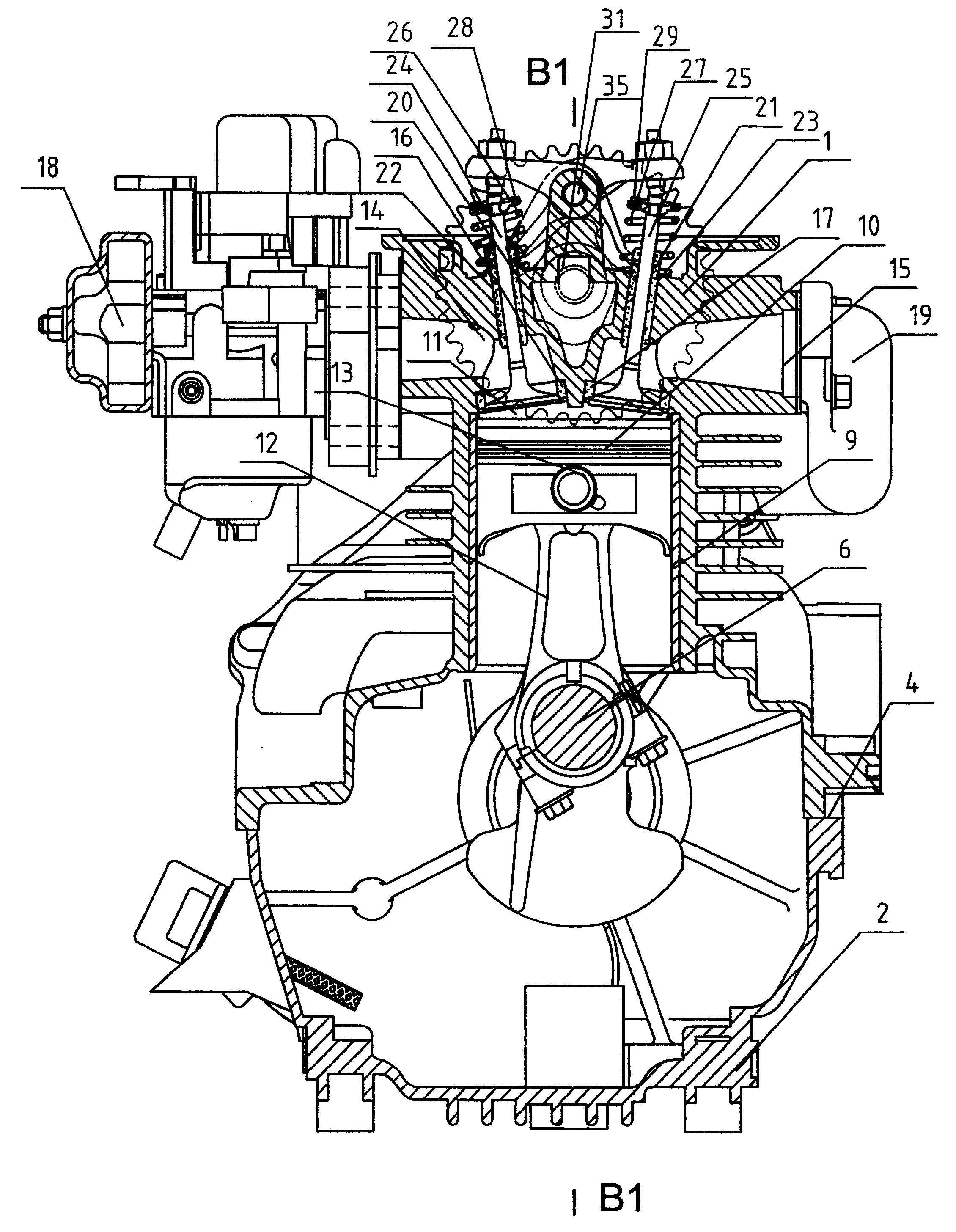
图1是本发明结构纵剖视图(实施例一)。Fig. 1 is a longitudinal sectional view of the structure of the present invention (embodiment 1).
图2是本发明结构A-A的剖视图。Figure 2 is a cross-sectional view of structure A-A of the present invention.
图3是本发明结构图2的俯视图。Fig. 3 is a top view of the structure Fig. 2 of the present invention.
图4是本发明结构图3的B-B剖视图。Fig. 4 is a B-B cross-sectional view of Fig. 3 of the present invention.
图5是本发明结构气门操纵机构的分解图。Fig. 5 is an exploded view of the valve operating mechanism of the present invention.
图6是本发明结构的纵剖视图(实施例二)。Fig. 6 is a longitudinal sectional view of the structure of the present invention (embodiment 2).
图7是本发明结构图6的俯视图。Fig. 7 is a top view of Fig. 6 of the structure of the present invention.
图8是本发明结构图6的C-C剖视图。Fig. 8 is a C-C cross-sectional view of Fig. 6 of the present invention.
具体实施方式 Detailed ways
下面本发明将结合附图中的实施例作进一步描述:Below the present invention will be further described in conjunction with the embodiment in the accompanying drawing:
本发明主要由机体1、曲轴箱盖2、气缸盖罩3、结合面4、螺栓5、曲轴6、轴承7、8、气缸筒9、活塞10、燃烧室11、连杆组12、活塞销13、进气道14、排气道15、进气门座16、排气门座17、进气管18、排气管19、进气门导管20、排气门导管21、孔22、孔23、进气门24、排气门25、进气门弹簧26、排气门弹簧27、气门弹簧座28、气门弹簧座29、轴30、凸轮轴31、正时齿轮32、正时链条或皮带33、气门摇臂座34、摇臂轴35、进气门摇臂36(上端38、下端39)、排气门摇臂37(上端40、下端41)、气门调节螺钉42a、气门调节螺母43a、气门调节螺钉42b、气门调节螺母43b、发动机缸盖44、链条室45、上半曲轴箱46、凸轮47、火花塞48、进气凸轮49及排气凸轮50等组成。The present invention mainly consists of
实施例一:(进排气门共用一个凸轮)Embodiment 1: (the intake and exhaust valves share one cam)
本发明是单气缸风冷型顶置凸轮式汽油机,发动机主要件机体1、曲轴箱盖2、气缸盖罩3由铝合金或镁合金模压成型。机体1与曲轴箱盖2是在结合面4处斜分,并用多组螺栓5来连接。机体1与曲轴箱盖2的结合面4穿过曲轴轴线A1-A1和气缸轴线B1-B1。曲轴6的旋转是通过穿在两端的轴承7和轴承8,轴承7支承在体机1上,轴承8支承在曲轴箱盖2上。The invention is a single-cylinder air-cooled overhead cam gasoline engine. The engine
发动机机体1由气缸盖44、上曲轴半箱46、气缸筒9、链条室45采用螺栓连接形成一体,气缸盖罩3固定在气缸盖44上,在气缸筒9中安装活塞10,燃烧室11由活塞10、机体1、气缸筒9形成。活塞10通过连杆组12连接曲轴6,连杆组12与曲轴6的连接是可以相对自由旋转的。活塞10和连杆组12的连接是通过一个活塞销13,并可相对自由摆动。The
发动机机体1上部还有预先铸出成形的进气道14、排气道15,进气道14和排气道15分别位于气缸轴线B1-B1的两侧。进气道14的一端通到燃烧室11,并在交接处压配一个进气门座16,另一端在机体1的外面形成一平面,在此与进气管18相连。排气道15的一端也通到燃烧室11,在交接处压配一个排气门座17,另一端在机体1关于气缸轴线B1-B1对称的另一面形成一平面,在此与排气管19相连。进气道14内与气缸轴线B1-B1倾斜加工一孔22用来压配一进气门导管20,该孔与进气门座16同轴,在进气门导管20内穿有一进气门24,进气门24上装有一气门弹簧座28,在气门弹簧座28与机体1之间,与进气门24同轴装有一进气门弹簧26,因此进气门弹簧26压缩时,进气门24下移,脱离进气门座16,进气通畅;进气门弹簧26复位时,进气门24上移,贴住进气门座16,进气阻塞。排气道15内与气缸轴线B1-B1倾斜加工一孔23用来压配一排气门导管21,该孔与排气门座17同轴,在排气门导管21内穿有一排气门25,排气门25上装有一气门弹簧座29,在气门弹簧座29与机体1之间,与排气门25同轴装有一排气门弹簧27,因此排气门弹簧27压缩时,排气门25下移,脱离排气门座17,排气通畅;排气门弹簧27复位时,排气门25上移,贴住排气门座17,排气阻塞。The upper part of the
在机体1上部还通过一根轴30装配有一根凸轮轴31,凸轮轴31布置在两个气门的中间位置,凸轮轴31平行于曲轴6,并且与气缸轴线B1-B1相交,垂直。在凸轮轴31设有一体形成的凸轮47,凸轮轴31可以在轴30上自由旋转。凸轮轴31的旋转主要通过曲轴6的带动。曲轴6上装有一个正时齿轮32,正时齿轮32过盈压配在曲轴6上,与曲轴一起旋转;在链条室45中容纳有一根链条或皮带33,正时链条或皮带33将其上刻有齿形的凸轮轴31与正时齿轮32连接在一起;并且通过齿形的个数保证曲轴6与凸轮轴31的转速比为2∶1。凸轮轴31上的凸轮47偏离不正对进排气门24、25,在机体1上部设有突出的气门摇臂座34,摇臂轴35安装在气门摇臂座34内,摇臂轴35布置在进气门摇臂36与排气门摇臂37的中间位置,摇臂轴35与曲轴6平行,并且穿过并垂直气缸轴线B1-B1,位于凸轮轴31的上部;由于气门的倾斜,摇臂很方便的布置在两个气门的中间位置;摇臂轴35的一端做成突出,用以于气缸盖罩3接触防止滑脱。进气门摇臂36分为两段,上端38、下端39,上端38上装有气门调节螺钉42a气门调节螺母43a与进气门24根部相连,下端39成一圆弧形与凸轮47相接触;排气门摇臂37分为两段,上端40、下端41,上端40上装有气门调节螺钉42b气门调节螺母43b与排气门25根部相连,下端41成一圆弧形与凸轮47相接触;进排气门摇臂36、37共用一根摇臂轴35,以及一个凸轮47,并且进排气门摇臂36、37交叉穿在摇臂轴35上从而连接在机体1上,使进气门摇臂36的上端38、下端39,排气门摇臂37的上端40、下端41分别位于曲轴轴线A1-A1的两边,并且进气门摇臂36、排气门摇臂37能绕着摇臂轴35摆动。A
其工作过程:Its working process:
当曲轴6旋转时,曲轴6通过正时链条33带动凸轮轴31以1/2的转速旋转,从而借助凸轮47推动与之接触的进气门摇臂36下端39、排气门摇臂37的下端41。使进气门摇臂36上端38、排气门摇臂37的上端40摆动,克服进气门弹簧26和排气门弹簧27的阻力,打开进气门24及排气门25。When the
另一方面,进气门摇臂36下端39、排气门摇臂37的下端41贴靠在凸轮47,当凸轮47继续旋转对进气门摇臂36、排气门摇臂37没有压力时,进气门24及排气门25依靠进气门弹簧26和排气门弹簧27的弹力打开,并且完成进气门摇臂36、排气门摇臂37的复位。On the other hand, the
实施例二:(进、排气门分别使用一个凸轮)Embodiment two: (intake and exhaust valve use a cam respectively)
发动机机体1由气缸盖44、容纳活塞的气缸筒9、链条室45、上曲轴半箱46结合形成一体,机体上气缸筒9的顶部形成一燃烧室11,火花塞48在此处用于定时的向燃烧室内点火。The
机体1上部还有预先铸出成形的进气道14排气道15,进气道14和排气道15分别位于气缸轴线B1-B1的两侧。进气道14的一端通到燃烧腔11,并在交接处压配一个进气门座16,另一端在机体1的外面形成一平面。排气道15的一端也通到燃烧室11,在交接处压配一个排气门座17,另一端在机体1关于气缸轴线B1-B1对称的另一面形成一平面。进气道14内与气缸轴线B1-B1倾斜加工一孔22用来压配一进气门导管20,该孔与进气门座16同轴,在进气门导管20内穿有一进气门24,进气门24上装有一气门弹簧座28,在气门弹簧座28与机体1之间,与进气门24同轴装有一进气门弹簧26,因此进气门弹簧26压缩时,进气门24下移,脱离进气门座16,进气通畅;进气门弹簧26复位时,进气门24上移,贴住进气门座16,进气阻塞。排气道15内与气缸轴线B1-B1倾斜加工一孔23用来压配一排气门导管21,该孔与排气门座17同轴,在排气门导管21内穿有一排气门25,排气门25上装有一气门弹簧座29,在气门弹簧座29与机体1之间,与排气门25同轴装有一排气门弹簧27,因此排气门弹簧27压缩时,排气门25下移,脱离排气门座17,排气通畅;排气门弹簧27复位时,排气门25上移,贴住排气门座17,排气阻塞。The upper part of the
在机体1上部还通过一根轴30装配有一根凸轮轴31,凸轮轴31布置在两个气门的中间位置,凸轮轴31平行于曲轴6,并且与气缸轴线B1-B1相交,垂直。在凸轮轴31设有一体形成的进气凸轮49、排气凸轮50,分别驱动进气门24、排气门25。A
在机体1上部还有一突出的气门摇臂座34,用于装配一根摇臂轴35,摇臂轴35与曲轴6平行,并且穿过并垂直气缸轴线B1-B1,位于凸轮轴30的上部;由于气门的倾斜,摇臂很方便的布置在两个气门的中间位置。进气门摇臂36分为两段,上端38、下端39,上端38上装有气门调节螺钉42a气门调节螺母43a与进气门24根部相连,下端39成一圆弧形与进气凸轮49相接触;排气门摇臂37分为两段,上端40、下端41,上端40上装有气门调节螺钉42b气门调节螺母43b与排气门25根部相连,下端41成一圆弧形与排气凸轮50相接触;进排气门摇臂36、37共用一根摇臂轴35,并且进排气门摇臂36、37穿在摇臂轴35上从而连接在机体1上,使进气门摇臂36的上端38、下端39,排气门摇臂37的上端40、下端41分别位于曲轴轴线A1-A1的两边,并且进气门摇臂36、排气门摇臂37能绕着摇臂轴35摆动。There is also a protruding valve
这样当发动机工作时,同样的凸轮轴旋转,进排气凸轮相应的打开进排气门,继续旋转时又由于回位弹簧的作用相应的关闭进排气门,来保证发动机的四个冲程的可靠工作。In this way, when the engine is working, the same camshaft rotates, and the intake and exhaust cams open the intake and exhaust valves accordingly, and when the camshaft continues to rotate, the intake and exhaust valves are closed correspondingly due to the action of the return spring, so as to ensure the four strokes of the engine. work reliably.
Claims (6)
Priority Applications (2)
| Application Number | Priority Date | Filing Date | Title |
|---|---|---|---|
| CNB2006100971650A CN100434657C (en) | 2006-10-28 | 2006-10-28 | Four-stroke overhead cam engine |
| PCT/CN2007/001081 WO2008052402A1 (en) | 2006-10-28 | 2007-04-03 | Four stroke overhead cam engine |
Applications Claiming Priority (1)
| Application Number | Priority Date | Filing Date | Title |
|---|---|---|---|
| CNB2006100971650A CN100434657C (en) | 2006-10-28 | 2006-10-28 | Four-stroke overhead cam engine |
Publications (2)
| Publication Number | Publication Date |
|---|---|
| CN1944963A CN1944963A (en) | 2007-04-11 |
| CN100434657C true CN100434657C (en) | 2008-11-19 |
Family
ID=38044534
Family Applications (1)
| Application Number | Title | Priority Date | Filing Date |
|---|---|---|---|
| CNB2006100971650A Active CN100434657C (en) | 2006-10-28 | 2006-10-28 | Four-stroke overhead cam engine |
Country Status (2)
| Country | Link |
|---|---|
| CN (1) | CN100434657C (en) |
| WO (1) | WO2008052402A1 (en) |
Families Citing this family (6)
| Publication number | Priority date | Publication date | Assignee | Title |
|---|---|---|---|---|
| CN101482053B (en) * | 2008-01-10 | 2012-06-27 | 光阳工业股份有限公司 | In-cylinder injection cylinder head configuration mechanism |
| CN102383927A (en) * | 2011-03-28 | 2012-03-21 | 山东华盛中天机械集团有限公司 | Four-stroke gasoline engine |
| CN103277166B (en) | 2013-06-17 | 2016-06-08 | 苏州科瓴精密机械科技有限公司 | Otto cycle engine |
| CN109252947B (en) * | 2018-09-30 | 2023-10-20 | 苏州帕瓦麦斯动力有限公司 | A four-stroke engine and a permanent magnet generator set driven by it |
| CN109281754B (en) * | 2018-10-12 | 2024-04-26 | 苏州帕瓦麦斯动力有限公司 | A range-extending fuel generator set for electric vehicles |
| JP6506467B1 (en) * | 2018-12-26 | 2019-04-24 | 株式会社石川エナジーリサーチ | Opposed piston type engine |
Citations (3)
| Publication number | Priority date | Publication date | Assignee | Title |
|---|---|---|---|---|
| US5706769A (en) * | 1994-09-07 | 1998-01-13 | Honda Giken Kogyo Kabushiki Kaisha | OHC engine |
| CN1204004A (en) * | 1997-06-25 | 1999-01-06 | 三菱重工业株式会社 | Structure of overhead-valve internal combustion engine and manufacturing method for the same |
| CN201027572Y (en) * | 2006-10-28 | 2008-02-27 | 无锡开普动力有限公司 | Four-stroke overhead cam engine |
Family Cites Families (6)
| Publication number | Priority date | Publication date | Assignee | Title |
|---|---|---|---|---|
| JPS59135308U (en) * | 1983-03-02 | 1984-09-10 | 三菱自動車工業株式会社 | Camshaft support structure |
| JP3295296B2 (en) * | 1996-03-15 | 2002-06-24 | 株式会社クボタ | Monoblock engine |
| US5884593A (en) * | 1996-04-24 | 1999-03-23 | Tecumseh Products Company | Head and overhead camshaft assembly for an internal combustion engine |
| JP2002327606A (en) * | 2001-04-27 | 2002-11-15 | Sanshin Ind Co Ltd | Rocker arm structure for engine valve system |
| JP4382010B2 (en) * | 2005-06-23 | 2009-12-09 | 本田技研工業株式会社 | Engine valve gear |
| CN100567708C (en) * | 2006-03-08 | 2009-12-09 | 无锡开普动力有限公司 | Lubricating structure of engine |
-
2006
- 2006-10-28 CN CNB2006100971650A patent/CN100434657C/en active Active
-
2007
- 2007-04-03 WO PCT/CN2007/001081 patent/WO2008052402A1/en not_active Ceased
Patent Citations (3)
| Publication number | Priority date | Publication date | Assignee | Title |
|---|---|---|---|---|
| US5706769A (en) * | 1994-09-07 | 1998-01-13 | Honda Giken Kogyo Kabushiki Kaisha | OHC engine |
| CN1204004A (en) * | 1997-06-25 | 1999-01-06 | 三菱重工业株式会社 | Structure of overhead-valve internal combustion engine and manufacturing method for the same |
| CN201027572Y (en) * | 2006-10-28 | 2008-02-27 | 无锡开普动力有限公司 | Four-stroke overhead cam engine |
Also Published As
| Publication number | Publication date |
|---|---|
| WO2008052402A1 (en) | 2008-05-08 |
| CN1944963A (en) | 2007-04-11 |
Similar Documents
| Publication | Publication Date | Title |
|---|---|---|
| US7185615B2 (en) | Variable stroke engine | |
| US6276324B1 (en) | Overhead ring cam engine with angled split housing | |
| US7918199B2 (en) | V-type engine | |
| US8136501B2 (en) | Variable stroke engine | |
| CA2466613A1 (en) | Decompression device for internal combustion engine | |
| WO2008052402A1 (en) | Four stroke overhead cam engine | |
| CN100453790C (en) | general engine | |
| CA2650895A1 (en) | Cylinder head structure in four-cycle engine | |
| US7305938B2 (en) | Stroke-variable engine | |
| AU2007306907B2 (en) | 4-cycle engine | |
| JP2008240714A (en) | Cam profile structure of a 4-cycle internal combustion engine | |
| US7082917B2 (en) | Engine | |
| CN201027572Y (en) | Four-stroke overhead cam engine | |
| JP2019183732A (en) | Opposed piston internal combustion engine | |
| WO2008098433A1 (en) | An overhead camshaft engine | |
| WO2004083609A1 (en) | Rotation prevention device for rocker arm | |
| JP3767716B2 (en) | Spark-ignition 4-cycle internal combustion engine with supercharged pump | |
| JP2003314237A (en) | Engine | |
| KR100305447B1 (en) | Intake/exhaust valve device of engine | |
| JP2008274863A (en) | Air-cooled V-type engine | |
| CN2911193Y (en) | Valve control gear of engine | |
| JP4011306B2 (en) | OHC engine | |
| CN201013411Y (en) | Overhead cam engine | |
| JP3916297B2 (en) | Overhead camshaft internal combustion engine | |
| JPWO2025027725A5 (en) |
Legal Events
| Date | Code | Title | Description |
|---|---|---|---|
| C06 | Publication | ||
| PB01 | Publication | ||
| C10 | Entry into substantive examination | ||
| SE01 | Entry into force of request for substantive examination | ||
| C14 | Grant of patent or utility model | ||
| GR01 | Patent grant | ||
| PP01 | Preservation of patent right | ||
| PP01 | Preservation of patent right |
Effective date of registration: 20191011 Granted publication date: 20081119 |
|
| PD01 | Discharge of preservation of patent |
Date of cancellation: 20201120 Granted publication date: 20081119 |
|
| PD01 | Discharge of preservation of patent | ||
| TR01 | Transfer of patent right |
Effective date of registration: 20260104 Address after: 215000 Jiangsu Province Suzhou City Gusu District Pingjiang Street Beiyuan Road No. 75 Building E 1st Floor Room 1025 Patentee after: Suzhou Tao Dolphin Information Consulting Co.,Ltd. Country or region after: China Address before: 214028 Jiangsu Province Wuxi City Wuxi New District Wangzhuang Industrial Supporting Park Phase III Patentee before: WUXI KIPOR POWER Co.,Ltd. Country or region before: China |
|
| TR01 | Transfer of patent right | ||
| TR01 | Transfer of patent right |
Effective date of registration: 20260401 Address after: 215000 Jiangsu Province Suzhou City China (Jiangsu) Free Trade Zone Suzhou Area Suzhou Industrial Park Jinji Lake Avenue 88 Artificial Intelligence Industry Park G4-301-172 Unit Patentee after: Suzhou Yipu Power Technology Co.,Ltd. Country or region after: China Address before: 215000 Jiangsu Province Suzhou City Gusu District Pingjiang Street Beiyuan Road No. 75 Building E 1st Floor Room 1025 Patentee before: Suzhou Tao Dolphin Information Consulting Co.,Ltd. Country or region before: China |
|
| TR01 | Transfer of patent right |